Embed Size (px)
Citation preview
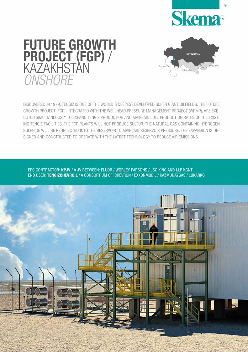
KAZAKHSTAN
Caspian Sea
Uzbekistan
Kyrgyzstan
DISCOVERED IN 1979, TENGIZ IS ONE OF THE WORLD’S DEEPEST DEVELOPED SUPER GIANT OILFIELDS. THE FUTURE
GROWTH PROJECT (FGP), INTEGRATED WITH THE WELLHEAD PRESSURE MANAGEMENT PROJECT (WPMP), ARE EXE-
CUTED SIMULTANEOUSLY TO EXPAND TENGIZ PRODUCTION AND MAINTAIN FULL PRODUCTION RATES OF THE EXIST-
ING TENGIZ FACILITIES. THE FGP PLANTS WILL NOT PRODUCE SULFUR. THE NATURAL GAS CONTAINING HYDROGEN
SULPHIDE WILL BE RE-INJECTED INTO THE RESERVOIR TO MAINTAIN RESERVOIR PRESSURE. THE EXPANSION IS DE-
SIGNED AND CONSTRUCTED TO OPERATE WITH THE LATEST TECHNOLOGY TO REDUCE AIR EMISSIONS.
FUTURE GROWTH PROJECT (FGP) / KAZAKHSTAN ONSHORE
EPC CONTRACTOR: KPJV / A JV BETWEEN: FLUOR / WORLEY PARSONS / JSC KING AND LLP KGNTEND USER: TENGIZCHEVROIL / A CONSORTIUM OF: CHEVRON / EXXONMOBIL / KAZMUNAYGAS / LUKARKO


THE EQUIPMENT
Skema provided the following main
equipment for the 110 kV Core sub-
station:
> LV switchgear and MCCs com-
plete with auto-transfer scheme,
momentary synchronizing be-
tween incomers, switchgear and
transformer protection, control
and metering equipment
> Distribution boards, bus ducts,
distribution transformers and
PLC panel
> Electrical/instruments and F&G
systems
> HVAC system
> Hydrosanitary system
> Bridge crane
GE’s scope of supply included the fol-
lowing main equipment:
> 110 kV Gas Insulated Switchgear
(GIS) with associated protection,
control and metering equipment
> Utility metering for the 110 kV
interconnection with the Client’s
network
> UPS system and batteries

THE CORE SUBSTATION
The Core substation consists of 32
modules, which were prefabricated,
assembled, sand-blasted, painted
and bolted to form a unique structure.
After completion of the structural and
architectural assembly, the internal
equipment was installed and the sub-
station was tested.
The modules were then disassem-
bled and shipped to Kazakhstan.
The Core substation is built over 2 lev-
els, each divided into rooms. More in
detail, the ground floor includes:
110 kV GIS AREA – Steel struc-
ture made by assembled units which
contain the gas insulated switchgear
(GIS). A 1.5 t bridge crane is installed
over the top floor of the GIS area for
switchgear maintenance purposes.
ELECTRICAL ROOM – 2 transformers
feeding the LV switchgear, UPS, bat-
tery box, and the distribution boards
are installed in the electrical room on
the ground floor, which includes also
an office and a restroom.
BATTERY ROOM – Batteries are locat-
ed on specific racks in this room, which
is equipped with an eye wash facility
and a trolley to move the batteries.
The mezzanine floor hosts:
HVAC ROOM – The HVAC LV switch-
gear and PLC panel, the main air
conditioning equipment and the duct
system for the whole substation are
in the HVAC room, which includes
also 2 chemical filters and 2 fans.
INSTRUMENT EQUIPMENT ROOM
This room has been designed for
the control panels supplied by GE.
Access ladders, entrance, emer-
gency and maintenance service
doors complete the substation, and
5 removable panels ensure easy
instal lat ion and maintenance of
the bigger and heavier equipment.
A system of walkways at different
heights serve the electro/instru-
mental paths, starting from the low-
er part beneath the floor beams, all
through the intermediate section, up
to the upper part of the substation,
ensuring the connection among the
main equipment such as GIS, trans-
formers, switchgear, lighting, small
power and sensors from the various
rooms.

ENGINEERING
Skema’s scope of work included all
the design and engineering activities,
which were developed through stud-
ies, calculations, verification and val-
idation, and a series of specific de-
tai led procedures to ensure the
correct sequence of operations to
assemble the modules (e.g. removal
of temporary structural parts; seal-
ing; special tools needed to move the
modules; all that is needed to prepare
the structures for transportation).
3D MODEL
Skema’s supply included a 3D model of
the substation, which gives a 360° view
of the whole substation: structural and
architectural parts, electrical and instru-
mentation, HVAC and control disciplines.
The 3D modeling of the substation and
its equipment enables Skema to ensure
a thorough and consistent monitoring of
the most critical areas, a functional di-
mensional verification of the correct po-
sition of the internal elements in the
various areas, and the removal of any
clashes between the elements of the dis-
ciplines that form the model. It also ena-
bles Skema to interface with its Client
efficiently, giving a unique access key to
the project for the success of both the
engineering and construction phases.
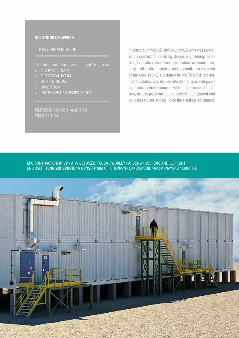
SOLUTIONS DELIVERED
110 KV CORE SUBSTATION
The substation is composed of the following areas: > 110 KV GIS ROOM > ELECTRICAL ROOM > BATTERY ROOM > HVAC ROOM > INSTRUMENT EQUIPMENT ROOM
DIMENSIONS (M) 56 X 14.48 X 7.9 WEIGHT (T) 750
In consortium with GE Grid Solutions, Skema was award-
ed the contract for the sizing, design, engineering, mate-
rials, fabrication, inspection, non-destructive examination,
shop-testing, documentation and preparation for shipment
of the Core 110 kV substation for the TCO FGP project.
The substation was divided into 32 transportable pack-
aged sub-modules complete with integral support struc-
ture, access platforms, stairs, electrical equipment and
building services and including the electrical equipment.
EPC CONTRACTOR: KPJV / A JV BETWEEN: FLUOR / WORLEY PARSONS / JSC KING AND LLP KGNTEND USER: TENGIZCHEVROIL / A CONSORTIUM OF: CHEVRON / EXXONMOBIL / KAZMUNAYGAS / LUKARKO