Embed Size (px)
Citation preview

Fusion of RedundantInformation in Brake-By-WireSystems Using a Fuzzy Voter
REZA HOSEINNEZHAD
ALIREZA BAB-HADIASHARSwinburne University of Technology
In safety critical systems such as brake-by-wire, fault tolerance
is usually provided by virtue of having redundant sensors and
processing hardware. The redundant information provided by such
components should be properly fused to achieve a reliable estimate
of the safety critical variable that is sensed or processed by the
redundant sensors or hardware. Voting methods are well-known
solutions for this category of fusion problems. In this paper, a
new voting method, using a fuzzy system for decision-making, is
presented. The voted output of the proposed scheme is a weighted
average of the sensors signals where the weights are calculated based
on the antecedents and consequences of some fuzzy rules in a rule-
base. In a case study, we have tested the fuzzy voter along with the
well-known majority voting method for a by-wire brake pedal that
is equipped with a displacement sensor and two force sensors. Our
experimental results show that the performance of the proposed
voting method is desirable in the presence of short circuits to ground
or supply, excessive noise and sensor drifts. Voting error (in terms
of mean square error) is reduced by 82% by the proposed fuzzy
voting method, compared to majority voting.
Manuscript received December 28, 2004; revised September 30, 2005and April 25, 2006.
Refereeing of this contribution was handled by Professor David Hall.
This research work was supported by Research Centre for AdvancedBy-Wire Technologies (RABiT) and Pacifica Group Technologies Pty.Ltd.
Authors’ address: Faculty of Engineering and Industrial Sciences,Swinburne University of Technology, Hawthorn, Victoria 3122, Aus-tralia, E-mail: ([email protected], [email protected]).
1557-6418/06/$17.00 c° 2006 JAIF
1. INTRODUCTION
Brake-by-wire is a frontier technology that will al-low many braking functions to switch to electronic ac-tuation. Its deployment will lead to more effective andsafe braking systems, elimination of hydraulic technol-ogy, release of space and reduction of maintenance.Design and implementation of brake-by-wire systemshas recently attracted interest from researchers in au-tomotive and control engineering [9—12, 17]. The gen-eral architecture of a brake-by-wire system is shown (inschematic form) in Fig. 1. The figure shows that a largevariety of sensors are utilised in a brake-by-wire sys-tem and therefore their consistent operation is vital forthe functionality of such a system. To achieve a highlevel of coherency amongst such a large collection ofsensors (mandated by the safety requirement of a brakesystem), the use of sophisticated data fusion techniquesis unavoidable.
Fig. 1. A schematic architecture of a brake-by-wire system.
A brake-by-wire system, by nature, is a safety criti-cal system and therefore fault tolerance is a vitally im-portant characteristic of this system. As a result, a brake-by-wire system is designed in such way that many of itsessential information would be derived from a varietyof sources (sensors) and be handled by more than thebare necessity hardware. Three main types of redun-dancy usually exist in a brake-by-wire system:
1) Redundant sensors in safety critical componentssuch as the brake pedal in Fig. 1.2) Redundant copies of some signals that are of par-
ticular safety importance such as displacement and forcemeasurements of the brake pedal copied by multipleprocessors in the pedal interface unit in Fig. 1.3) Redundant hardware to perform important pro-
cessing tasks such as multiple processors for the elec-tronic controller unit (ECU) in Fig. 1.
52 JOURNAL OF ADVANCES IN INFORMATION FUSION VOL. 1, NO. 1 JULY 2006
Reliability, fault tolerance and accuracy are the maintargeted outcomes of the fusion techniques that shouldbe developed especially for redundancy resolution in-side a brake-by-wire system. In order to utilise the exist-ing redundancy, voting algorithms need to be evaluated,modified and adopted to meet the stringent requirementsof a brake-by-wire system.Several well known voting algorithms have been
widely used in fault tolerant systems such as avionicsand railway systems [6—8, 13] and fault tolerant VLSIcircuits [4—6, 8, 13]. The n-input majority voter [1] pro-duces a correct result if at least [(n+1)=2] voter inputsmatch each other. In cases of no majority, the voter gen-erates an exception flag, which can be detected by thesystem supervisor to move the system toward a safestate. As an extended version of majority voter, plural-ity voter [2] implements “m out of n” voting, wherem is less than a strict majority. Median voter is a mid-value selection algorithm. Assuming an odd number ofredundant inputs, this algorithm successively eliminatespairs of outlying values until a single result remains.The weighted average voter [21], on the other hand,calculates the weighted mean of its redundant input val-ues. Parhami [16] examined the performance of differ-ent voting techniques, in terms of their execution time,and proposed efficient implementations of a variety ofalgorithms.There is no agreement checking in weighted average
and median voters [15]. Hence, they are not appropriatefor safety critical applications such as braking. In thecase of lack of majority agreement, majority votersgive no result in the output and instead a flag is set.In a brake-by-wire system, however, “no result” is notacceptable as the output of fusion. Instead, a status bit isgenerated for each sensor.1 If the sensors do not agree,invalidity of the voter output will be deduced from thestatus bits. Another problem with a majority voter is itsconsiderable output discontinuity in the event of long-time disagreements [14, 18]. Latif-Shabgahi and hiscolleagues tried to solve this problem by introducinga smoothing voter in which an agreement-checkingthreshold is adaptively set when the voter produces noresult. While their proposed method results in a lowernumber of no result events in the output of the voter,such events are not completely eliminated.As an alternative solution for the problem, we pro-
pose to use the mean of agreeing sensors as the outputof a majority voter and use their median value if there isno agreement. In this method that we call hard voting,a status bit is set if the sensors agree, and reset if theydon’t. The main issue in this voting method is how toset the geometric distance threshold [18] value by whichsensor agreement is checked. Due to sensor conversionerrors, there is almost always a distance between twoagreeing sensors of different types. Therefore, distance
1Henceforward, by sensor, a source of information is intended. It canbe a redundant sensor, a redundant signal or a redundant processor.
threshold should be large enough to prevent incorrectdecisions about sensor agreements in the presence ofsensor conversion errors. A large value for the distancethreshold in the hard voting method will, however, giverise to late fault detection if the fault causes a grad-ual change in the sensory signal. Such faulty gradualchanges in sensory signals usually happen because ofdrifts, short circuits,2 and sensor noise that graduallyincreases with temperature.Genetic algorithms have also been applied for voting
[19]. This approach, however, is only efficient whenused with off-line calculations and in particular, forcases when the population of redundant components islarge.In this paper we propose a new voting method,
called soft voting (in contrast to its alternative, hardvoting), using a fuzzy logic paradigm. By using fuzzylogic rule-base inference, a faulty sensor is graduallyremoved from the output of our proposed soft voter.Instead of status bits, a faultiness measure is definedfor each sensor that gradually increases in the eventof faults. Although fuzzy inference and fuzzy systemshave been utilised for sensor fusion in drive-by-wireapplications, they have been employed merely to gen-erate control commands or signal estimates for controland estimation applications in drive-by-wire technology[3, 20].The fuzzy voter introduced in this paper is novel in
the sense that it actually realises an adaptive weightedaveraging mechanism for voting in which the weightsare intelligently determined by the fuzzy inference en-gine. This inference engine is designed in such a waythat faulty sensors are automatically detected based onthe geometric distance between their outputs and othersensory measurements. As such distances grow, theweights corresponding to faulty sensors gradually de-crease toward zero. To our knowledge, fuzzy systemshave not been applied for voting in such a scheme.For voting applications in systems with redundant
sensors (or information sources), our proposed softvoter has the following advantages compared to otherexisting methods: Firstly, it does not output “no result.”Secondly, it is capable of early detection and rejectionof faulty sensors. Thirdly, its noise tolerance is higherthan existing methods (due to the automatic fault de-tection and noise rejection phenomenon realised by thefuzzy inference machine). In addition, the output of ourproposed voter does not suddenly jump or fall in caseof signal short-circuits, and finally its computationalcomplexity is comparable with simple voting methodslike majority voters (particularly for a small number ofsensors). These advantages all together make the pro-posed voter significantly efficient for real-time votingin redundant multi-sensor systems. We emphasize thatmost of the many voting techniques in the current lit-
2The RC filters that are connected to the inputs of ADCs (analog todigital converters) cause a gradual change in sensory signals when ashort circuit happens.
HOSEINNEZHAD & BAB-HADIASHAR: FUSION OF REDUNDANT INFORMATION IN BRAKE-BY-WIRE SYSTEMS 53
erature have been designed for voting on multiple deci-sions (equivalent to fusion in decision or symbol level)while the method proposed in this paper and the meth-ods reviewed in this section are applicable to voting onredundant signals i.e., the cases involving signal-levelfusion.We introduce our soft voting method in Section 2.
Implementation of a soft voter for fusion of the redun-dant information provided by three sensors of a brakepedal is presented in Section 3. Then comparative exper-imental results of hard and soft voting methods on realsensory data will also be given in this section. Amongthe voting methods reviewed in this paper, hard voting isthe closest to the proposed fuzzy voter in a sense that itis also a weighted-averaging voter but the weights havebinary values and jump to zero in the case of a faultysensor. Our soft voter is capable of early detection offaulty sensors and makes the weights gradually decreasetoward zero in case of such faults. Due to their similarityand their meaningful difference, the fuzzy soft voter andthe hard voter have been compared in Section 3 as a faircomparison. Section 4 concludes this paper. Althoughour method has been implemented and experimentedfor fusion of redundant safety critical components in abrake-by-wire system, the general scheme of our pro-posed fuzzy voter, explained in Section 2, can be appliedto fuse redundant information in any application withsafety critical issues and fault tolerance requirements.
2. PROPOSED SOFT VOTING METHOD
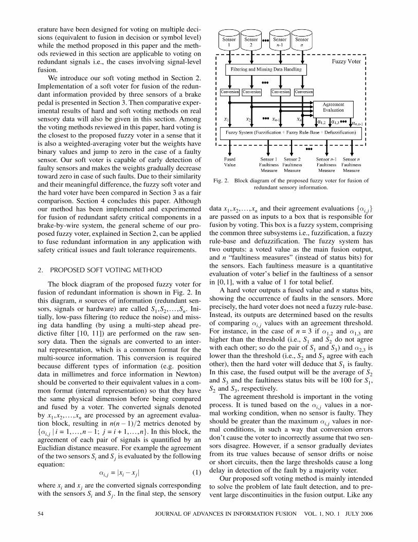
The block diagram of the proposed fuzzy voter forfusion of redundant information is shown in Fig. 2. Inthis diagram, n sources of information (redundant sen-sors, signals or hardware) are called S1,S2, : : : ,Sn. Ini-tially, low-pass filtering (to reduce the noise) and miss-ing data handling (by using a multi-step ahead pre-dictive filter [10, 11]) are performed on the raw sen-sory data. Then the signals are converted to an inter-nal representation, which is a common format for themulti-source information. This conversion is requiredbecause different types of information (e.g. positiondata in millimetres and force information in Newton)should be converted to their equivalent values in a com-mon format (internal representation) so that they havethe same physical dimension before being comparedand fused by a voter. The converted signals denotedby x1,x2, : : : ,xn are processed by an agreement evalua-tion block, resulting in n(n¡1)=2 metrics denoted byf®i,j j i= 1, : : : ,n¡1; j = i+1, : : : ,ng. In this block, theagreement of each pair of signals is quantified by anEuclidian distance measure. For example the agreementof the two sensors Si and Sj is evaluated by the followingequation:
®i,j = jxi¡ xj j (1)
where xi and xj are the converted signals correspondingwith the sensors Si and Sj . In the final step, the sensory
Fig. 2. Block diagram of the proposed fuzzy voter for fusion ofredundant sensory information.
data x1,x2, : : : ,xn and their agreement evaluations f®i,jgare passed on as inputs to a box that is responsible forfusion by voting. This box is a fuzzy system, comprisingthe common three subsystems i.e., fuzzification, a fuzzyrule-base and defuzzification. The fuzzy system hastwo outputs: a voted value as the main fusion output,and n “faultiness measures” (instead of status bits) forthe sensors. Each faultiness measure is a quantitativeevaluation of voter’s belief in the faultiness of a sensorin [0,1], with a value of 1 for total belief.A hard voter outputs a fused value and n status bits,
showing the occurrence of faults in the sensors. Moreprecisely, the hard voter does not need a fuzzy rule-base.Instead, its outputs are determined based on the resultsof comparing ®i,j values with an agreement threshold.For instance, in the case of n= 3 if ®1,2 and ®1,3 arehigher than the threshold (i.e., S1 and S2 do not agreewith each other; so do the pair of S1 and S3) and ®2,3 islower than the threshold (i.e., S2 and S3 agree with eachother), then the hard voter will deduce that S1 is faulty.In this case, the fused output will be the average of S2and S3 and the faultiness status bits will be 100 for S1,S2 and S3, respectively.The agreement threshold is important in the voting
process. It is tuned based on the ®i,j values in a nor-mal working condition, when no sensor is faulty. Theyshould be greater than the maximum ®i,j values in nor-mal conditions, in such a way that conversion errorsdon’t cause the voter to incorrectly assume that two sen-sors disagree. However, if a sensor gradually deviatesfrom its true values because of sensor drifts or noiseor short circuits, then the large thresholds cause a longdelay in detection of the fault by a majority voter.Our proposed soft voting method is mainly intended
to solve the problem of late fault detection, and to pre-vent large discontinuities in the fusion output. Like any
54 JOURNAL OF ADVANCES IN INFORMATION FUSION VOL. 1, NO. 1 JULY 2006

Fig. 3. Brake pedal and its sensors in our case study.
fuzzy system, ®i,j inputs are fuzzified first. We definethree fuzzy sets of Large, Medium and Small agree-ments by their membership functions. These definitionsare based on empirical maximum values of ®i,j , derivedfrom measurements and conversions. In practice, wecollect some measurements from fine sensors and calcu-late the ®i,j values for each multi-sensory measurement.In case of triangular membership functions, if the max-imum of ®i,j values is ®max, then breaking points of theSmall fuzzy set are 0—1:7®max, the breaking points ofthe Medium fuzzy set are ®max—1:7®max—2:3®max, andthe breaking points of the Large fuzzy set are 1:7®max—2:3®max. Generally, the application experts can deter-mine the proper levels of ®i,j set as breaking points forSmall, Medium and Large fuzzy sets. Based on the logicof majority voting, each fuzzy rule in the rule-base de-termines a voted output and n faultiness measures. Forexample to vote three sensors, a typical fuzzy rule isexpressed as follows:
IFS1 and S2 agreement is SmallAND S2 and S3 agreement is LargeAND S3 and S1 agreement is SmallTHENThe fused output is the average of S2 and S3AND S1 faultiness is LargeAND S2 faultiness is SmallAND S3 faultiness is Small.
This rule explains what is logically expected as avoting result if S1 does not agree with the other twosensors. The final defuzzified fusion output is calculatedas a weighted average of all possible expected outputsby the following equation:
Fused Output =MXi=1
(wiOi)
,MXi=1
wi (2)
where M is the number of rules in the rule-base, Oi isthe fused output as it appears in the consequence of theith fuzzy rule and the weight wi is the product of mem-bership values of the conjoined parts of the antecedentof the rule. If the exemplar rule given above is the kthfuzzy rule in the rule-base, then Ok = (x2 + x3)=2 wherex2 and x3 are the filtered sensory signals of S2 and S3after conversion to the internal representation, as shownin Fig. 2. These weights smoothly change from 0 to 1 orreverse, and the fused output is smoothly switched fromone vote to the other, hence the name soft voter. Sensorfaultiness measures are defuzzified into crisp outputs bya fuzzy centroid method. In this method, a fuzzy numberis transformed to crisp by taking the centre of gravity ofits membership function. More precisely, if Y is a fuzzynumber with its membership functions determinedas ¹Y(y), then the centroid crisp of Y is given asbelow:
y =Z +1
¡1®¹Y(®)d®:
3. EXPERIMENTAL RESULTS
We implemented our fuzzy voter to fuse the redun-dant information provided by three sensors mounted ona brake-by-wire pedal. Two sensors measure the forceand the third sensor measures the pedal displacement.Although the sensors are different, they are redundantsources of information in the sense that they providemeasurements for the same quantity: driver’s brake de-mand. A photograph of the brake pedal and its sensorsare displayed in Fig. 3.As we have shown in the brake-by-wire diagram
in Fig. 1, the displacement and force signals are pre-processed (low-pass filtering and missing data handling)by fault tolerant processors in the pedal interface unit
HOSEINNEZHAD & BAB-HADIASHAR: FUSION OF REDUNDANT INFORMATION IN BRAKE-BY-WIRE SYSTEMS 55

and then transferred to four wheels via a fault tolerantcommunication bus (e.g. a LIN-bus). The processedsensory data are also sent to an electronic control unit(ECU) that includes a number of redundant processorsgenerating the high level braking commands, such asanti-skid braking system (ABS), vehicle stability control(VSC) or traction control (TC).In order to provide a reliable estimate for the driver’s
brake demand, pedal sensor data are voted in the ECU,where the resulting brake demand is then fused with theother vehicle sensor data (e.g. wheel speed or INS–Inertial Navigation System–sensors like accelerome-ters and gyros) to generate four final brake commands.To activate the brake actuators, these commands are sentto the local controllers in the four brake callipers via afault tolerant time-triggered communication network. Iffor any reason the ECU is faulty then pedal sensorydata will be voted in the local controller of each wheelunit, leading to generation of a brake response on eachwheel. The main purpose of voting is to detect sensorfaults (such as excessive noise, short circuits or sensordrifts) and to remove the effects of faulty measurementsfrom the brake demand. In the presence of a fault or asubstantial level of noise in sensor signals, they willnot agree with each other. A voter should detect thesedisagreements and use them to identify faulty sensors.A hard voter simply discards faulty sensor data and out-puts the average of agreeing sensors.Fig. 4 shows a block diagram of the pedal sensor
fusion scheme which is the revised version of the di-agram shown in Fig. 2, for our experiments. S1 andS2 are the two force sensors giving f1 and f2, and S3is the displacement sensor with its signal denoted byx. Force is the quantity selected as the internal rep-resentation for fusion of the three sensors. In otherwords, the pedal displacement signal is converted toequivalent force signals f̂1 and f̂2 to be compared withthe signals provided by the other two sensors. In or-der to perform this conversion, a model is required tomathematically relate the three signals x, f1 and f2.The passive push-return mechanism of the pedal canbe modelled with an ideal spring in parallel with adamper, as shown in Fig. 5. The two force sensors arelocated at the two ends of the paralleled spring anddamper model. Since the acceleration of pedal move-ments is too small to be considered in the model, theeffect of the pedal mass is neglected. Thus, the twoforce sensor measurements are very close and havebeen simply labelled with f in Fig. 5 and the follow-ing equations. Based on the simplified damper-springmodel, the following equation expresses the measuredforce signals in terms of the measured displacementsignal:
f = kx+b _x (3)
where k and b are the spring and damping factors,respectively.
Fig. 4. Block diagram of pedal sensor fusion.
Fig. 5. A simplified model of the pedal and its sensors.
In order to validate the model and estimate its pa-rameters, we ran a number of experiments and collectedthe three sensors measurements. In these experiments,the pedal set was installed in a car and a driver used itfor different braking scenarios such as continuous softbrakes, frequent push-release and panic brakes. Usingthe collected sensory data, we examined the linearitybetween force, displacement and velocity using a leastsquares (LS) technique. More precisely, we utilised therecorded signals f, x and dx=dt and obtained a LS esti-mate of the parameters k and b in (3). This resulted in alow correlation coefficient and large difference betweenthe measured forces f and the force values f̂ = kx+ b _x.These results showed a poor linear relationship betweenthose quantities and a single linear model that woulddescribe the repeated experiments could not be found.
56 JOURNAL OF ADVANCES IN INFORMATION FUSION VOL. 1, NO. 1 JULY 2006
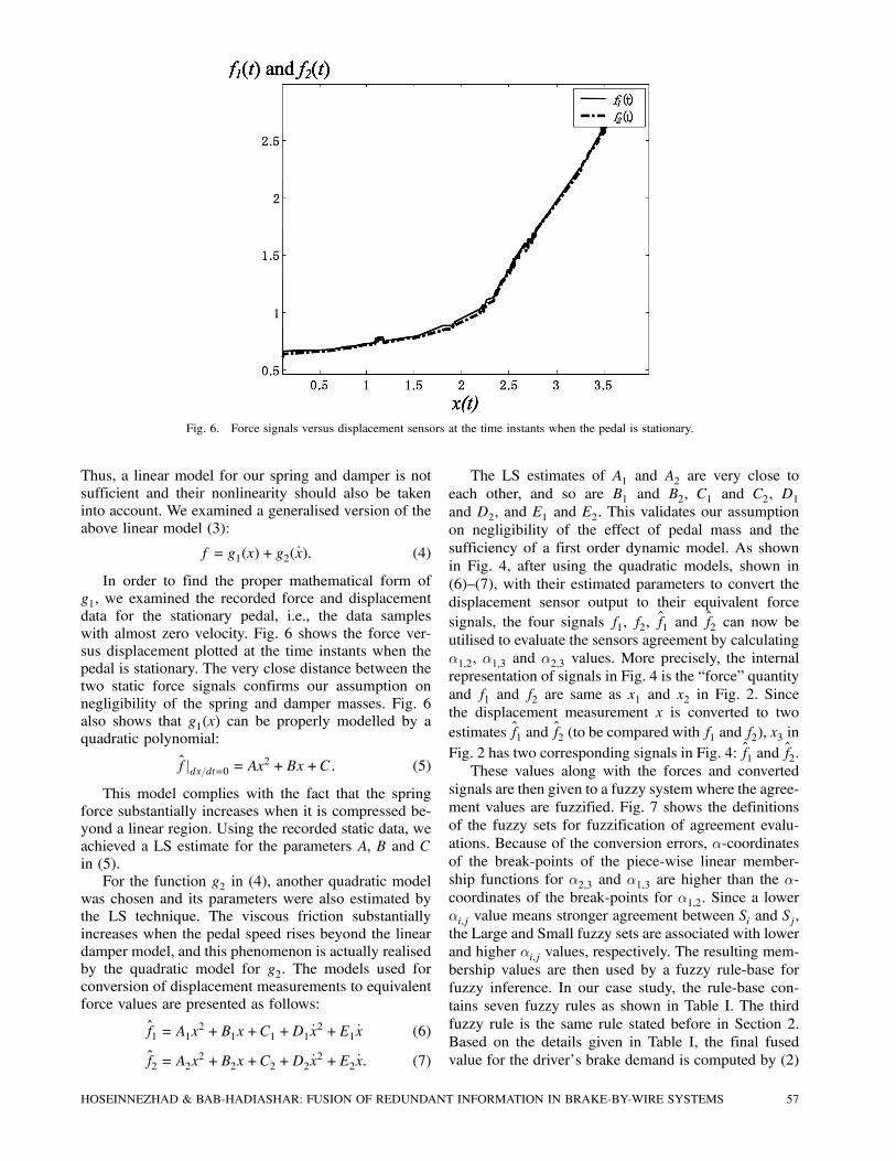
Fig. 6. Force signals versus displacement sensors at the time instants when the pedal is stationary.
Thus, a linear model for our spring and damper is notsufficient and their nonlinearity should also be takeninto account. We examined a generalised version of theabove linear model (3):
f = g1(x) + g2( _x): (4)
In order to find the proper mathematical form ofg1, we examined the recorded force and displacementdata for the stationary pedal, i.e., the data sampleswith almost zero velocity. Fig. 6 shows the force ver-sus displacement plotted at the time instants when thepedal is stationary. The very close distance between thetwo static force signals confirms our assumption onnegligibility of the spring and damper masses. Fig. 6also shows that g1(x) can be properly modelled by aquadratic polynomial:
f̂jdx=dt=0 = Ax2 +Bx+C: (5)
This model complies with the fact that the springforce substantially increases when it is compressed be-yond a linear region. Using the recorded static data, weachieved a LS estimate for the parameters A, B and Cin (5).For the function g2 in (4), another quadratic model
was chosen and its parameters were also estimated bythe LS technique. The viscous friction substantiallyincreases when the pedal speed rises beyond the lineardamper model, and this phenomenon is actually realisedby the quadratic model for g2. The models used forconversion of displacement measurements to equivalentforce values are presented as follows:
f̂1 = A1x2 +B1x+C1 +D1 _x
2 +E1 _x (6)
f̂2 = A2x2 +B2x+C2 +D2 _x
2 +E2 _x: (7)
The LS estimates of A1 and A2 are very close toeach other, and so are B1 and B2, C1 and C2, D1and D2, and E1 and E2. This validates our assumptionon negligibility of the effect of pedal mass and thesufficiency of a first order dynamic model. As shownin Fig. 4, after using the quadratic models, shown in(6)—(7), with their estimated parameters to convert thedisplacement sensor output to their equivalent forcesignals, the four signals f1, f2, f̂1 and f̂2 can now beutilised to evaluate the sensors agreement by calculating®1,2, ®1,3 and ®2,3 values. More precisely, the internalrepresentation of signals in Fig. 4 is the “force” quantityand f1 and f2 are same as x1 and x2 in Fig. 2. Sincethe displacement measurement x is converted to twoestimates f̂1 and f̂2 (to be compared with f1 and f2), x3 inFig. 2 has two corresponding signals in Fig. 4: f̂1 and f̂2.These values along with the forces and converted
signals are then given to a fuzzy system where the agree-ment values are fuzzified. Fig. 7 shows the definitionsof the fuzzy sets for fuzzification of agreement evalu-ations. Because of the conversion errors, ®-coordinatesof the break-points of the piece-wise linear member-ship functions for ®2,3 and ®1,3 are higher than the ®-coordinates of the break-points for ®1,2. Since a lower®i,j value means stronger agreement between Si and Sj ,the Large and Small fuzzy sets are associated with lowerand higher ®i,j values, respectively. The resulting mem-bership values are then used by a fuzzy rule-base forfuzzy inference. In our case study, the rule-base con-tains seven fuzzy rules as shown in Table I. The thirdfuzzy rule is the same rule stated before in Section 2.Based on the details given in Table I, the final fusedvalue for the driver’s brake demand is computed by (2)
HOSEINNEZHAD & BAB-HADIASHAR: FUSION OF REDUNDANT INFORMATION IN BRAKE-BY-WIRE SYSTEMS 57
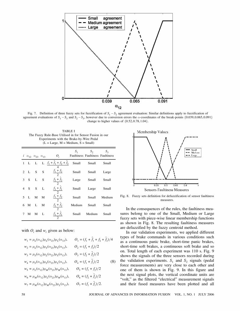
Fig. 7. Definition of three fuzzy sets for fuzzification of S1 ¡ S2 agreement evaluation: Similar definitions apply to fuzzification ofagreement evaluations of S1 ¡ S3 and S2¡ S3, however due to conversion errors the ®-coordinates of the break-points f0:039,0:065,0:091g
change to higher values of f0:52,0:78,1:04g.
TABLE IThe Fuzzy Rule-Base Utilised in for Sensor Fusion in our
Experiments with the Brake-by-Wire Pedal(L = Large, M=Medium, S = Small)
S1 S2 S3i ®12 ®23 ®13 Oi Faultiness Faultiness Faultiness
1 L L L f1 + f̂1 +f2 + f̂24
Small Small Small
2 L S S f1 +f22
Small Small Large
3 S L S f2 + f̂22
Large Small Small
4 S S L f1 + f̂12
Small Large Small
5 L M M f1 +f22
Small Small Medium
6 M L M f2 + f̂22
Medium Small Small
7 M M L f1 + f̂12
Small Medium Small
with Oi and wi given as below:
w1 = ¹L(®12)¹L(®23)¹L(®13), O1 = (f1 + f̂1 +f2 + f̂2)=4
w2 = ¹L(®12)¹S(®23)¹S(®13), O2 = (f1 +f2)=2
w3 = ¹S(®12)¹L(®23)¹S(®13), O3 = (f2 + f̂2)=2
w4 = ¹S(®12)¹S(®23)¹L(®13), O4 = (f1 + f̂1)=2 (8)
w5 = ¹L(®12)¹M(®23)¹M(®13), O5 = (f1 +f2)=2
w6 = ¹M(®12)¹L(®23)¹M(®13), O6 = (f2 + f̂2)=2
w7 = ¹M(®12)¹M(®23)¹L(®13), O7 = (f1 + f̂1)=2:
Fig. 8. Fuzzy sets definition for defuzzification of sensor faultinessmeasures.
In the consequences of the rules, the faultiness mea-sures belong to one of the Small, Medium or Largefuzzy sets with piece-wise linear membership functionsas shown in Fig. 8. The resulting faultiness measuresare defuzzified by the fuzzy centroid method.In our validation experiments, we applied different
types of brake commands in various conditions suchas a continuous panic brake, short-time panic brakes,short-time soft brakes, a continuous soft brake and soon. Total length of each experiment was 110 s. Fig. 9shows the signals of the three sensors recorded duringthe validation experiments. S1 and S2 signals (pedalforce measurements) are very close to each other andone of them is shown in Fig. 9. In this figure andthe next signal plots, the vertical coordinate units are“volt,” as the filtered “electrical” measurement signalsand their fused measures have been plotted and all
58 JOURNAL OF ADVANCES IN INFORMATION FUSION VOL. 1, NO. 1 JULY 2006
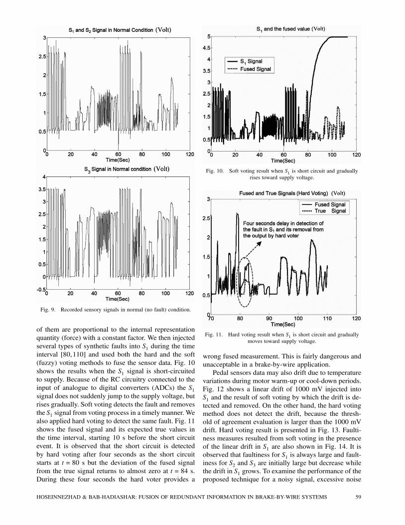
Fig. 9. Recorded sensory signals in normal (no fault) condition.
of them are proportional to the internal representationquantity (force) with a constant factor. We then injectedseveral types of synthetic faults into S1 during the timeinterval [80,110] and used both the hard and the soft(fuzzy) voting methods to fuse the sensor data. Fig. 10shows the results when the S1 signal is short-circuitedto supply. Because of the RC circuitry connected to theinput of analogue to digital converters (ADCs) the S1signal does not suddenly jump to the supply voltage, butrises gradually. Soft voting detects the fault and removesthe S1 signal from voting process in a timely manner. Wealso applied hard voting to detect the same fault. Fig. 11shows the fused signal and its expected true values inthe time interval, starting 10 s before the short circuitevent. It is observed that the short circuit is detectedby hard voting after four seconds as the short circuitstarts at t= 80 s but the deviation of the fused signalfrom the true signal returns to almost zero at t= 84 s.During these four seconds the hard voter provides a
Fig. 10. Soft voting result when S1 is short circuit and graduallyrises toward supply voltage.
Fig. 11. Hard voting result when S1 is short circuit and graduallymoves toward supply voltage.
wrong fused measurement. This is fairly dangerous andunacceptable in a brake-by-wire application.Pedal sensors data may also drift due to temperature
variations during motor warm-up or cool-down periods.Fig. 12 shows a linear drift of 1000 mV injected intoS1 and the result of soft voting by which the drift is de-tected and removed. On the other hand, the hard votingmethod does not detect the drift, because the thresh-old of agreement evaluation is larger than the 1000 mVdrift. Hard voting result is presented in Fig. 13. Faulti-ness measures resulted from soft voting in the presenceof the linear drift in S1 are also shown in Fig. 14. It isobserved that faultiness for S1 is always large and fault-iness for S2 and S3 are initially large but decrease whilethe drift in S1 grows. To examine the performance of theproposed technique for a noisy signal, excessive noise
HOSEINNEZHAD & BAB-HADIASHAR: FUSION OF REDUNDANT INFORMATION IN BRAKE-BY-WIRE SYSTEMS 59
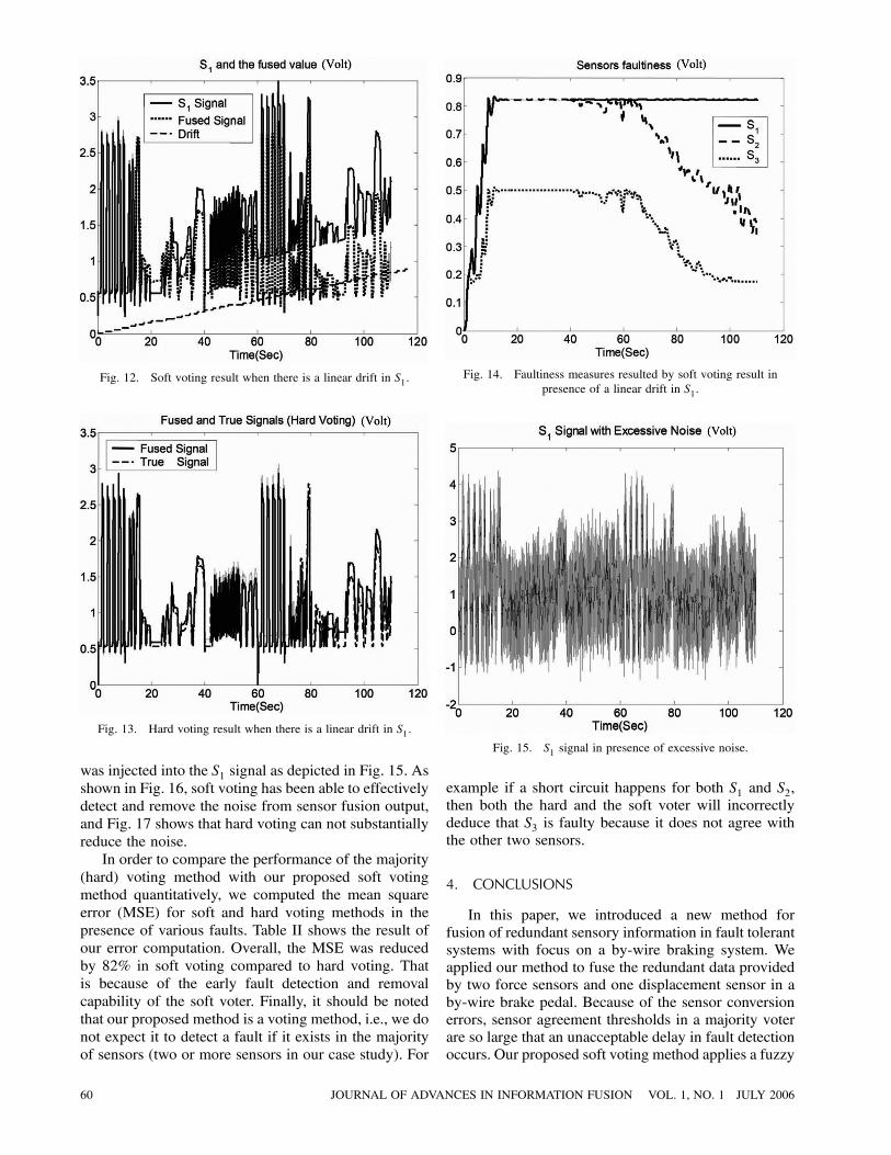
Fig. 12. Soft voting result when there is a linear drift in S1.
Fig. 13. Hard voting result when there is a linear drift in S1.
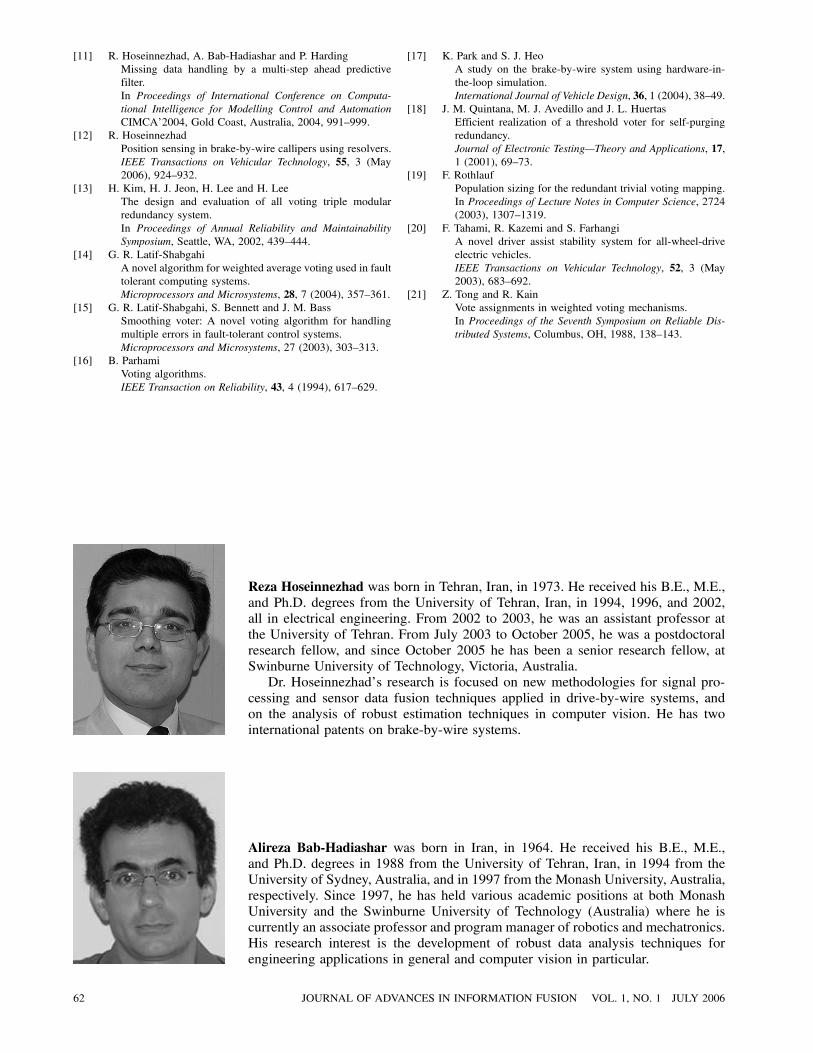
was injected into the S1 signal as depicted in Fig. 15. Asshown in Fig. 16, soft voting has been able to effectivelydetect and remove the noise from sensor fusion output,and Fig. 17 shows that hard voting can not substantiallyreduce the noise.In order to compare the performance of the majority
(hard) voting method with our proposed soft votingmethod quantitatively, we computed the mean squareerror (MSE) for soft and hard voting methods in thepresence of various faults. Table II shows the result ofour error computation. Overall, the MSE was reducedby 82% in soft voting compared to hard voting. Thatis because of the early fault detection and removalcapability of the soft voter. Finally, it should be notedthat our proposed method is a voting method, i.e., we donot expect it to detect a fault if it exists in the majorityof sensors (two or more sensors in our case study). For
Fig. 14. Faultiness measures resulted by soft voting result inpresence of a linear drift in S1.
Fig. 15. S1 signal in presence of excessive noise.
example if a short circuit happens for both S1 and S2,then both the hard and the soft voter will incorrectlydeduce that S3 is faulty because it does not agree withthe other two sensors.
4. CONCLUSIONS
In this paper, we introduced a new method forfusion of redundant sensory information in fault tolerantsystems with focus on a by-wire braking system. Weapplied our method to fuse the redundant data providedby two force sensors and one displacement sensor in aby-wire brake pedal. Because of the sensor conversionerrors, sensor agreement thresholds in a majority voterare so large that an unacceptable delay in fault detectionoccurs. Our proposed soft voting method applies a fuzzy
60 JOURNAL OF ADVANCES IN INFORMATION FUSION VOL. 1, NO. 1 JULY 2006
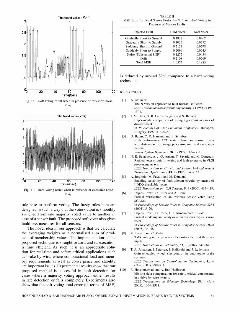
Fig. 16. Soft voting result when in presence of excessive noisein S1.
Fig. 17. Hard voting result when in presence of excessive noisein S1.
rule-base to perform voting. The fuzzy rules here aredesigned in such a way that the voter output is smoothlyswitched from one majority voted value to another incase of a sensor fault. The proposed soft voter also givesfaultiness measures for all sensors.The novel idea in our approach is that we calculate
the averaging weights as a normalised sum of prod-ucts of membership values. The implementation of theproposed technique is straightforward and its executionis time efficient. As such, it is an appropriate solu-tion for real-time and safety critical applications suchas brake-by-wire, where computational load and mem-ory requirements as well as convergence and stabilityare important issues. Experimental results show that ourproposed method is successful in fault detection forcases where a majority voting approach either resultsin late detection or fails completely. Experiments alsoshow that the soft voting total error (in terms of MSE)
TABLE IIMSE Error for Pedal Sensor Fusion by Soft and Hard Voting in
Presence of Various Faults
Injected Fault Hard Voter Soft Voter
Gradually Short to Ground 0.1932 0.0367Gradually Short to Supply 0.1033 0.0272Suddenly Short to Ground 0.2123 0.0298Suddenly Short to Supply 0.2099 0.0245Noise (Substantial SNR) 0.1277 0.0434
Drift 0.2108 0.0269Total MSE 1.0572 0.1885
is reduced by around 82% compared to a hard votingtechnique.
REFERENCES
[1] A. AvizienisThe N-version approach to fault-tolerant software.IEEE Transactions on Software Engineering, 1 (1985), 1491—1501.
[2] J. M. Bass, G. R. Latif-Shabgahi and S. BennettExperimental comparison of voting algorithms in cases ofdisagreement.In Proceedings of 23rd Euromicro Conference, Budapest,Hungary, 1997, 516—523.
[3] D. Baum, C. D. Hamann and E. SchubertHigh performance ACC system based on sensor fusionwith distance sensor, image processing unit, and navigationsystem.Vehicle System Dynamics, 28, 6 (1997), 327—338.
[4] N. E. Belabbes, A. J. Guterman, Y. Savaria and M. DagenaisRatioed voter circuit for testing and fault-tolerance in VLSIprocessing arrays.IEEE Transactions on Circuits and Systems I–FundamentalTheory and Applications, 43, 2 (1996), 143—152.
[5] A. Bogliolo, M. Favalli and M. DamianiEnabling testability of fault-tolerant circuits by means ofI-DDQ-checkable voters.IEEE Transactions on VLSI Systems, 8, 4 (2000), 415—419.
[6] S. Dajani-Brown, D. Cofer and A. BoualiFormal verification of an avionics sensor voter usingSCADE.In Proceedings of Lecture Notes in Computer Science, 3253(2004), 5—20.
[7] S. Dajani-Brown, D. Cofer, G. Hartmann and S. PrattFormal modeling and analysis of an avionics triplex sensorvoter.In Proceedings of Lecture Notes in Computer Science, 2648(2003), 34—48.
[8] M. Favalli and C. MetraTMR voting in the presence of crosstalk faults at the voterinputs.IEEE Transactions on Reliability, 53, 3 (2004), 342—348.
[9] T. A. Johansen, I. Petersen, J. Kalkkuhl and J. LudemannGain-scheduled wheel slip control in automotive brakesystems.IEEE Transactions on Control System Technology, 11, 6(Nov. 2003), 799—811.
[10] R. Hoseinnezhad and A. Bab-HadiasharMissing data compensation for safety-critical componentsin a drive-by-wire system.IEEE Transactions on Vehicular Technology, 54, 4 (July2005), 1304—1311.
HOSEINNEZHAD & BAB-HADIASHAR: FUSION OF REDUNDANT INFORMATION IN BRAKE-BY-WIRE SYSTEMS 61
[11] R. Hoseinnezhad, A. Bab-Hadiashar and P. HardingMissing data handling by a multi-step ahead predictivefilter.In Proceedings of International Conference on Computa-tional Intelligence for Modelling Control and AutomationCIMCA’2004, Gold Coast, Australia, 2004, 991—999.
[12] R. HoseinnezhadPosition sensing in brake-by-wire callipers using resolvers.IEEE Transactions on Vehicular Technology, 55, 3 (May2006), 924—932.
[13] H. Kim, H. J. Jeon, H. Lee and H. LeeThe design and evaluation of all voting triple modularredundancy system.In Proceedings of Annual Reliability and MaintainabilitySymposium, Seattle, WA, 2002, 439—444.
[14] G. R. Latif-ShabgahiA novel algorithm for weighted average voting used in faulttolerant computing systems.Microprocessors and Microsystems, 28, 7 (2004), 357—361.
[15] G. R. Latif-Shabgahi, S. Bennett and J. M. BassSmoothing voter: A novel voting algorithm for handlingmultiple errors in fault-tolerant control systems.Microprocessors and Microsystems, 27 (2003), 303—313.
[16] B. ParhamiVoting algorithms.IEEE Transaction on Reliability, 43, 4 (1994), 617—629.
Reza Hoseinnezhad was born in Tehran, Iran, in 1973. He received his B.E., M.E.,and Ph.D. degrees from the University of Tehran, Iran, in 1994, 1996, and 2002,all in electrical engineering. From 2002 to 2003, he was an assistant professor atthe University of Tehran. From July 2003 to October 2005, he was a postdoctoralresearch fellow, and since October 2005 he has been a senior research fellow, atSwinburne University of Technology, Victoria, Australia.Dr. Hoseinnezhad’s research is focused on new methodologies for signal pro-
cessing and sensor data fusion techniques applied in drive-by-wire systems, andon the analysis of robust estimation techniques in computer vision. He has twointernational patents on brake-by-wire systems.
Alireza Bab-Hadiashar was born in Iran, in 1964. He received his B.E., M.E.,and Ph.D. degrees in 1988 from the University of Tehran, Iran, in 1994 from theUniversity of Sydney, Australia, and in 1997 from the Monash University, Australia,respectively. Since 1997, he has held various academic positions at both MonashUniversity and the Swinburne University of Technology (Australia) where he iscurrently an associate professor and program manager of robotics and mechatronics.His research interest is the development of robust data analysis techniques forengineering applications in general and computer vision in particular.
[17] K. Park and S. J. HeoA study on the brake-by-wire system using hardware-in-the-loop simulation.International Journal of Vehicle Design, 36, 1 (2004), 38—49.
[18] J. M. Quintana, M. J. Avedillo and J. L. HuertasEfficient realization of a threshold voter for self-purgingredundancy.Journal of Electronic Testing–Theory and Applications, 17,1 (2001), 69—73.
[19] F. RothlaufPopulation sizing for the redundant trivial voting mapping.In Proceedings of Lecture Notes in Computer Science, 2724(2003), 1307—1319.
[20] F. Tahami, R. Kazemi and S. FarhangiA novel driver assist stability system for all-wheel-driveelectric vehicles.IEEE Transactions on Vehicular Technology, 52, 3 (May2003), 683—692.
[21] Z. Tong and R. KainVote assignments in weighted voting mechanisms.In Proceedings of the Seventh Symposium on Reliable Dis-tributed Systems, Columbus, OH, 1988, 138—143.
62 JOURNAL OF ADVANCES IN INFORMATION FUSION VOL. 1, NO. 1 JULY 2006