Embed Size (px)
Citation preview
Fusion of Medical Video ImagesAnd Tomographic Volumes
Fusion medizinischer Videobildermit tomographischen Volumendaten
Der Technischen Fakultat derUniversitat Erlangen-Nurnberg
zur Erlangung des Grades
DOKTOR-INGENIEUR
vorgelegt von
Michael Scheuering
Erlangen – 2003

Als Dissertation genehmigt vonder Technischen Fakultat der
Universitat Erlangen-Nurnberg
Tag der Einreichung: 12. Mai 2003Tag der Promotion: 24. 07. 2003Dekan: Prof. Dr. A. WinnackerBerichterstatter: Prof. Dr. G. Greiner
Prof. Dr. B. Preim
Abstract
Minimally invasive surgery has advanced rapidly in the last years because of theaccelerated convalescence of the patient. However, such interventions demand a lotof experience due to limited access to the field of operation. In particular, the trocarplacement and the orientation within the patient’s body are hampered. Throughthe invention of navigation hardware, the tracking of the surgical tools and cam-eras became possible, which revolutionized intra-operative image-guided surgerygenerally. Nowadays, there are a variety of applications that allow the navigationand guidance of tools with high accuracy, ranging from neurosurgical interventionsto osseous applications. In the case of minimally invasive liver surgery, one pos-sibility for intervention assistance is the fusion of laparoscopic video images andtomographic volumes at operation time in order to present orientational aids basedon navigation hardware. In this doctoral thesis, different fundamental techniquesare presented in order to merge video images and tomographic volumes with a focuson high interactivity. Therefore, new techniques and capabilities of modern graphicsadapters are exploited.
One application for fusion are augmented reality systems (ARS) which directlyproject pre-operative information onto the surgeon’s view, according to the pose ofthe surgical camera. In this context, real-time hardware-accelerated direct volumerendering based on fragment shader techniques is applied for augmentation of thelaparoscopic video images. Liver parenchyma, hepatic vessels and vascular territo-ries are overlaid for oncologic resection. Furthermore, fiducial markers are used forrigid registration. The system has been evaluated within real interventions.
Alternatively, laparoscopic video images can be applied in order to performreal-time scene exploration of the visceral space. A basic algorithm that utilizeshardware-acceleration for advanced view-dependent object texturing is presentedherein.
Furthermore, this thesis introduces a very fundamental and new technique forfast intensity-based 2D/3D non-rigid registration of multiple-view video images anddeformable volume renderings using mutual information as a voxel similarity met-ric. This algorithm requires a very fast and flexible volume rendering approachthat is based on interactive volume deformation. Therefore, two possibilities arepresented which are based on advanced hardware acceleration techniques includ-ing pixel shaders and dependent texture reads as a supplement to 3D texture ap-proaches.
iii

While image-guided intra-operative assistance is essential, pre-operative plan-ning tools are necessary in order to become familiar with the individual pa-tient’s anatomy. In the case of osseous applications, this work presents a tool forsemi-automatic repositioning of bone fracture segments, based on C-arm modality,whereby the physician roughly positions the fragments. An exact alignment, how-ever, is achieved through an optimization procedure.
iv

Revision 1.0c©2003, Copyright Michael Scheuering
All Rights ReservedAlle Rechte vorbehalten
v

vi
Contents
Abstract iii
Table of Contents xi
List of Figures xii
List of Tables xiii
Listings xv
Acknowledgements xvii
I Introduction 1
1 Motivation 31.1 Contribution . . . . . . . . . . . . . . . . . . . . . . . . . . . . . . . . . . 51.2 Outline of the Work . . . . . . . . . . . . . . . . . . . . . . . . . . . . . . 7
2 Minimally Invasive Procedures and Navigation 92.1 Minimally Invasive Liver Interventions . . . . . . . . . . . . . . . . . . 9
2.1.1 Historical Outline . . . . . . . . . . . . . . . . . . . . . . . . . . . 92.1.2 Clinical Setup in the Operating Room . . . . . . . . . . . . . . . 10
2.2 Navigation in Image-Guided Surgery . . . . . . . . . . . . . . . . . . . . 132.2.1 Navigation by Stereo Cameras . . . . . . . . . . . . . . . . . . . 142.2.2 Electro-mechanic and Robotic Navigation . . . . . . . . . . . . . 152.2.3 Optical Navigation . . . . . . . . . . . . . . . . . . . . . . . . . . 152.2.4 Electro-magnetic Navigation . . . . . . . . . . . . . . . . . . . . 172.2.5 Applications . . . . . . . . . . . . . . . . . . . . . . . . . . . . . . 18
vii
II Fusion of Video and Tomographic Images 21
3 Volume Rendering 233.1 Direct Volume Rendering . . . . . . . . . . . . . . . . . . . . . . . . . . . 233.2 Basics of Graphics Hardware . . . . . . . . . . . . . . . . . . . . . . . . 253.3 Standard 3D-Textures . . . . . . . . . . . . . . . . . . . . . . . . . . . . 273.4 2D-Multi-Texturing and Pixel Shaders . . . . . . . . . . . . . . . . . . . 283.5 Conclusion . . . . . . . . . . . . . . . . . . . . . . . . . . . . . . . . . . . 29
4 Augmented Reality - Fusion of CT and VR 314.1 Introduction . . . . . . . . . . . . . . . . . . . . . . . . . . . . . . . . . . 314.2 Previous Work . . . . . . . . . . . . . . . . . . . . . . . . . . . . . . . . . 334.3 Camera Calibration . . . . . . . . . . . . . . . . . . . . . . . . . . . . . . 34
4.3.1 Basics . . . . . . . . . . . . . . . . . . . . . . . . . . . . . . . . . . 344.3.2 Real-time Endoscopic Distortion Correction . . . . . . . . . . . . 36
4.4 Sensor Calibration . . . . . . . . . . . . . . . . . . . . . . . . . . . . . . 384.5 Augmented Reality and Image Overlay . . . . . . . . . . . . . . . . . . 40
4.5.1 Rigid Registration Procedure . . . . . . . . . . . . . . . . . . . . 404.5.2 System Composition . . . . . . . . . . . . . . . . . . . . . . . . . 41
4.6 Results . . . . . . . . . . . . . . . . . . . . . . . . . . . . . . . . . . . . . 424.6.1 Registration Accuracy . . . . . . . . . . . . . . . . . . . . . . . . 424.6.2 Performance . . . . . . . . . . . . . . . . . . . . . . . . . . . . . . 44
4.7 Conclusion and Discussion . . . . . . . . . . . . . . . . . . . . . . . . . . 46
5 Augmented Virtuality - 3D Scene Exploration 475.1 Introduction . . . . . . . . . . . . . . . . . . . . . . . . . . . . . . . . . . 475.2 Previous Work . . . . . . . . . . . . . . . . . . . . . . . . . . . . . . . . . 495.3 Algorithm Overview . . . . . . . . . . . . . . . . . . . . . . . . . . . . . . 50
5.3.1 Grid Generation . . . . . . . . . . . . . . . . . . . . . . . . . . . . 505.3.2 Calibration . . . . . . . . . . . . . . . . . . . . . . . . . . . . . . . 515.3.3 Registration . . . . . . . . . . . . . . . . . . . . . . . . . . . . . . 515.3.4 Texturing . . . . . . . . . . . . . . . . . . . . . . . . . . . . . . . . 52
5.4 Implementation . . . . . . . . . . . . . . . . . . . . . . . . . . . . . . . . 535.5 Results . . . . . . . . . . . . . . . . . . . . . . . . . . . . . . . . . . . . . 565.6 Application . . . . . . . . . . . . . . . . . . . . . . . . . . . . . . . . . . . 57
5.6.1 Post-operative Exploration . . . . . . . . . . . . . . . . . . . . . . 575.6.2 Augmentation by Direct Volume Rendering . . . . . . . . . . . . 58
5.7 Conclusion and Discussion . . . . . . . . . . . . . . . . . . . . . . . . . . 58
6 Interactive Volume Deformation 636.1 Previous Work . . . . . . . . . . . . . . . . . . . . . . . . . . . . . . . . . 646.2 Hexahedra Deformation . . . . . . . . . . . . . . . . . . . . . . . . . . . 65
6.2.1 Piecewise Linear Patches . . . . . . . . . . . . . . . . . . . . . . 65
viii
6.2.2 Vertex Constraints . . . . . . . . . . . . . . . . . . . . . . . . . . 666.2.3 Algorithm Implementation . . . . . . . . . . . . . . . . . . . . . . 686.2.4 Local Illumination and Fragment Shaders . . . . . . . . . . . . 696.2.5 Hierarchy Reduction . . . . . . . . . . . . . . . . . . . . . . . . . 716.2.6 Results . . . . . . . . . . . . . . . . . . . . . . . . . . . . . . . . . 72
6.3 Volume Deformation with 3D Dependent Textures . . . . . . . . . . . . 736.3.1 Implementation . . . . . . . . . . . . . . . . . . . . . . . . . . . . 766.3.2 Results . . . . . . . . . . . . . . . . . . . . . . . . . . . . . . . . . 76
6.4 Conclusion and Discussion . . . . . . . . . . . . . . . . . . . . . . . . . . 78
7 Non-rigid 2D/3D Registration 817.1 Previous Work . . . . . . . . . . . . . . . . . . . . . . . . . . . . . . . . . 827.2 Calibration and Navigation . . . . . . . . . . . . . . . . . . . . . . . . . 837.3 Registration . . . . . . . . . . . . . . . . . . . . . . . . . . . . . . . . . . 837.4 Higher-Order Deformation Model . . . . . . . . . . . . . . . . . . . . . . 86
7.4.1 Overview . . . . . . . . . . . . . . . . . . . . . . . . . . . . . . . . 877.4.2 Tensor Product Bezier Patches . . . . . . . . . . . . . . . . . . . 88
7.5 Results . . . . . . . . . . . . . . . . . . . . . . . . . . . . . . . . . . . . . 917.6 Conclusion and Discussion . . . . . . . . . . . . . . . . . . . . . . . . . . 92
III Medical Applications 95
8 Liver Intervention Assistance 978.1 Motivation . . . . . . . . . . . . . . . . . . . . . . . . . . . . . . . . . . . 988.2 Liver Anatomy and Function . . . . . . . . . . . . . . . . . . . . . . . . 99
8.2.1 Anatomy of the Liver . . . . . . . . . . . . . . . . . . . . . . . . . 998.2.2 Function of the Liver . . . . . . . . . . . . . . . . . . . . . . . . . 100
8.3 Pre-operative Planning . . . . . . . . . . . . . . . . . . . . . . . . . . . . 1018.4 Intra-operative Setup . . . . . . . . . . . . . . . . . . . . . . . . . . . . . 1038.5 Evaluation . . . . . . . . . . . . . . . . . . . . . . . . . . . . . . . . . . . 1048.6 Conclusion and Discussion . . . . . . . . . . . . . . . . . . . . . . . . . . 106
9 Repositioning of Bone Fracture Segments 1099.1 Introduction and Background . . . . . . . . . . . . . . . . . . . . . . . . 1099.2 Algorithm Overview . . . . . . . . . . . . . . . . . . . . . . . . . . . . . . 1119.3 Segmentation . . . . . . . . . . . . . . . . . . . . . . . . . . . . . . . . . 1119.4 Visualization . . . . . . . . . . . . . . . . . . . . . . . . . . . . . . . . . . 1119.5 Interaction and Collision Detection . . . . . . . . . . . . . . . . . . . . . 112
9.5.1 Building the Hierarchy . . . . . . . . . . . . . . . . . . . . . . . . 1139.5.2 Collision Detection . . . . . . . . . . . . . . . . . . . . . . . . . . 114
9.6 Optimization Process . . . . . . . . . . . . . . . . . . . . . . . . . . . . . 1169.7 Results . . . . . . . . . . . . . . . . . . . . . . . . . . . . . . . . . . . . . 118
ix
9.8 Conclusion and Discussion . . . . . . . . . . . . . . . . . . . . . . . . . . 119
IV Conclusion 121
10 Summary 12310.1 Future Challenges . . . . . . . . . . . . . . . . . . . . . . . . . . . . . . . 125
Bibliography 127
Index 141
V German Part 145
Kurzfassung 147
Inhaltsverzeichnis 149
Motivation 153
Zusammenfassung 159
x
List of Figures
1.1 Therapeutic process . . . . . . . . . . . . . . . . . . . . . . . . . . . . . . 4
2.1 Setup of minimally invasive surgery . . . . . . . . . . . . . . . . . . . . 102.2 Veress needle and trocar placement . . . . . . . . . . . . . . . . . . . . . 122.3 Simple pinhole camera model and stereo cameras. . . . . . . . . . . . . 142.4 Optical navigation systems . . . . . . . . . . . . . . . . . . . . . . . . . 162.5 Electro-magnetic navigation systems and receivers . . . . . . . . . . . 17
3.1 The graphics pipeline . . . . . . . . . . . . . . . . . . . . . . . . . . . . . 253.2 Multi-texturing . . . . . . . . . . . . . . . . . . . . . . . . . . . . . . . . 263.3 3D texture-based volume rendering . . . . . . . . . . . . . . . . . . . . . 273.4 2D texture-based volume rendering with multi-textures . . . . . . . . . 283.5 A visualization example of a liver. . . . . . . . . . . . . . . . . . . . . . . 29
4.1 Continuum of real-to-virtual environments . . . . . . . . . . . . . . . . 314.2 Camera calibration . . . . . . . . . . . . . . . . . . . . . . . . . . . . . . 344.3 Camera calibration patterns . . . . . . . . . . . . . . . . . . . . . . . . . 364.4 Endoscopic distortion correction . . . . . . . . . . . . . . . . . . . . . . . 374.5 Sensor calibration using hand-eye calibration . . . . . . . . . . . . . . . 394.6 Camera calibration results . . . . . . . . . . . . . . . . . . . . . . . . . . 434.7 3D rigid registration error . . . . . . . . . . . . . . . . . . . . . . . . . . 444.8 Image overlay results of rigid registration . . . . . . . . . . . . . . . . . 454.9 Performance results of rigid registration . . . . . . . . . . . . . . . . . . 46
5.1 Multiple-view video images of an object . . . . . . . . . . . . . . . . . . 485.2 Polygonal isosurface of a liver phantom . . . . . . . . . . . . . . . . . . 505.3 Conditions for texturing of a triangle . . . . . . . . . . . . . . . . . . . . 535.4 Texture-mapping and rendering into the p-buffer . . . . . . . . . . . . . 545.5 Texture atlas and final result . . . . . . . . . . . . . . . . . . . . . . . . 555.6 Results of texture-mapped images . . . . . . . . . . . . . . . . . . . . . 605.7 Intra-operative images of a minimally invasive liver surgery . . . . . . 615.8 Fusion of direct volume rendering and texture-mapped intra-
operative video images . . . . . . . . . . . . . . . . . . . . . . . . . . . . 62
6.1 Hexahedra model to deform volumes . . . . . . . . . . . . . . . . . . . . 65
xi
6.2 Subdivision hierarchy and vertex constraints . . . . . . . . . . . . . . . 666.3 Edge and face constraints . . . . . . . . . . . . . . . . . . . . . . . . . . 676.4 Axis-aligned slicing for volume deformation . . . . . . . . . . . . . . . . 686.5 Incorrect illumination with piecewise linear patches . . . . . . . . . . . 716.6 Hierarchical tree pruning . . . . . . . . . . . . . . . . . . . . . . . . . . 726.7 Performance of hexahedra volume deformation . . . . . . . . . . . . . . 736.8 Results of hexahedra volume deformation . . . . . . . . . . . . . . . . . 746.9 3D dependent texture lookup to deform volumes . . . . . . . . . . . . . 756.10 Performance of 3D dependent texture-based volume deformation . . . 786.11 Examples of 3D dependent texture-Based volume deformation . . . . . 79
7.1 Similarity of a video image of an object and its synthetic view . . . . . 847.2 Multiple views for robust non-rigid registration . . . . . . . . . . . . . 867.3 2D-Bezier deformation example . . . . . . . . . . . . . . . . . . . . . . . 897.4 Optimization results of a non-rigid registration . . . . . . . . . . . . . . 907.5 Resulting images of a non-rigid registration . . . . . . . . . . . . . . . . 94
8.1 Location of the liver in relation to its neighboring organs and the vas-cular system . . . . . . . . . . . . . . . . . . . . . . . . . . . . . . . . . . 99
8.2 Vascular territories of the liver . . . . . . . . . . . . . . . . . . . . . . . 1008.3 Example images of HEPAVISION . . . . . . . . . . . . . . . . . . . . . . 1018.4 Fixation of an electro-magnetic sensor to a laparoscopic camera . . . . 1038.5 Fiducial skin markers . . . . . . . . . . . . . . . . . . . . . . . . . . . . 1048.6 Results of a minimally invasive intervention simulation - planning of
incision points . . . . . . . . . . . . . . . . . . . . . . . . . . . . . . . . . 1058.7 Results of a minimally invasive intervention simulation - navigation
assistance . . . . . . . . . . . . . . . . . . . . . . . . . . . . . . . . . . . 106
9.1 Different examples of bone fractures . . . . . . . . . . . . . . . . . . . . 1109.2 Different hierarchical levels of a cow foot . . . . . . . . . . . . . . . . . 1139.3 Separating axes theorem . . . . . . . . . . . . . . . . . . . . . . . . . . . 1149.4 Depth-first traversal of two bones . . . . . . . . . . . . . . . . . . . . . . 1159.5 Volume of interest of two bone fragments . . . . . . . . . . . . . . . . . 1179.6 Initial position for optimization procedure. . . . . . . . . . . . . . . . . 1209.7 Results of an optimization procedure for bone repositioning . . . . . . 120
xii
List of Tables
4.1 Results of the camera calibration . . . . . . . . . . . . . . . . . . . . . . 434.2 Image overlay results using two phantoms . . . . . . . . . . . . . . . . 44
5.1 Performance and parameter setup for texture-mapped images . . . . . 56
7.1 Optimization results of a non-rigid registration . . . . . . . . . . . . . . 90
9.1 Calculation time to generate a hierarchy . . . . . . . . . . . . . . . . . . 1189.2 Calculation time for repositioning a cow foot . . . . . . . . . . . . . . . 118
xiii

xiv
Listings
4.1 OpenGL setup for fast endoscopic distortion correction . . . . . . . . . 386.1 OpenGL setup for 3D dependent texture reads . . . . . . . . . . . . . . 779.1 Pseudo code for depth-first traversal . . . . . . . . . . . . . . . . . . . . 116
xv

xvi
Acknowledgements
First of all, I want to thank my supervisor Prof. Dr. Gunther Greiner for his enor-mous support during my PhD thesis. His immense specialized knowledge, his coop-erativeness and the friendly relationship make him an exceptional person.
A special thank you goes to Dr. Rainer Graumann from Siemens Medical So-lutions, who gave me the opportunity to do research in an industrial and medicalenvironment. Without his confidence and funding, this project would not have beenpossible.
Special acknowledgement is due to Prof. Dr. Bernhard Preim for his friendshipand open-mindedness. My work has benefited enormously from his collaboration. Inaddition, I remain very grateful to Dr. Christof Rezk-Salama from whom I learneda lot. Due to his friendship and his esprit, motivating teamwork with innovativeresearch was possible.
I also would like to express my appreciation to Dr. Helmut Barfuß and GeroldHerold for their friendship and their contribution to this PhD thesis.
A very special thank you goes to Armin Schneider and Prof. Dr. Hubertus Feuss-ner for the close collaboration. Their clinical experience and interest for intra-operative applications pushed my work tremendously. In addition, also ChristianEckstein and Andrea Schenk deserve special acknowledgement for their assistanceand cooperativeness.
I express thanks to my colleagues Hendrik Ditt, Dr. Matthias Mitschke,Dr. Oliver Schutz, Dr. Karl Barth, Daniel Rinck, Dr. Peter Kipfer, Christian Vogel-gsang, Dr. Salvatore Spinello, Dr. Kai Hormann, Grzegorz Soza, Fernando Vega-Higuera, Dr. Ulf Labsik, Roman Sturm, Michael Bauer, Carsten Dachsbacher,Prof. Dr. Marc Stamminger, Maria Baroti and especially to my office mate FrankReck.
In particular, I am much obliged to my friends Andrea Murray (for proof reading),Dr. Ulf Hommel, Michael Schillig, Steffen, Silke and Lena Kritsch, Matthias Niese,Reinhard Hetzer and to the sailing group.
Finally and most of all, I would like to express my love and gratitude to myfamily, especially to my parents and my girlfriend Anna Grassle for helping me overmany difficulties and for supporting my career.
Michael Scheuering
xvii

xviii

Part I
Introduction

2
Chapter 1
Motivation
Amongst all surgical interventions schemes, needlescopic or minimally invasivesurgery has advanced rapidly in recent years. Not only has the instrument sizereduced immensely, but also the operative routine of the well-organized team isfar superior to anything that was achieved in previous decades in surgery of anykind. The economy of movement, the skillful use of the camera and the well-placedinstrumental retraction have revolutionized access to most areas of the abdomen.Additionally, the basic advantages of such surgical intervention schemes have be-come more and more apparent. It is an accepted opinion amongst surgeons thatminimally invasive therapy
• decreases parietal1 trauma
• decreases post-operative pain
• improves patients’ well-being
• improves cosmetic results and
• shortens hospital stay.
Thus, the benefits for both the patient and the Public Health Service System are ofimmense impact. Nevertheless, minimally invasive surgery using rigid and flexibleendoscopes are still subject to operative difficulties. Since the operating field cannotbe directly accessed (visual and tactile), the surgeon is forced to work with a camera-monitor system. Therefore, lesions and their locations within the patient’s body areoften difficult to determine. In addition, manipulations can only be accomplishedby surgical tools which makes tissue classification and consistency extremely com-plex. In consequence, the risk of iatrogenic2 diseases increases and minor diagnosticfindings can be missed.
1Pertaining to the walls of a cavity.2Induced inadvertently by the medical treatment or procedures or activity of a physician.
4 CHAPTER 1. MOTIVATION
Pre-operative
Computer-assistedplanning
Patient-specificmodel
Intra-operative
Computer-assisted
execution
Computer-assistedplanning
Updateplan
Updatemodel
Navigation
Imaging Modalities
Dia
gnosis
Pla
nnin
g Th
era
py
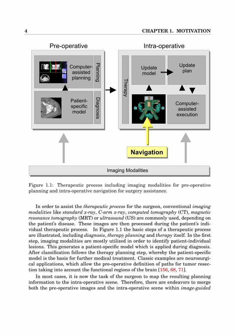
Figure 1.1: Therapeutic process including imaging modalities for pre-operativeplanning and intra-operative navigation for surgery assistance.
In order to assist the therapeutic process for the surgeon, conventional imagingmodalities like standard x-ray, C-arm x-ray, computed tomography (CT), magneticresonance tomography (MRT) or ultrasound (US) are commonly used, depending onthe patient’s disease. These images are then processed during the patient’s indi-vidual therapeutic process. In Figure 1.1 the basic steps of a therapeutic processare illustrated, including diagnosis, therapy planning and therapy itself. In the firststep, imaging modalities are mostly utilized in order to identify patient-individuallesions. This generates a patient-specific model which is applied during diagnosis.After classification follows the therapy planning step, whereby the patient-specificmodel is the basis for further medical treatment. Classic examples are neurosurgi-cal applications, which allow the pre-operative definition of paths for tumor resec-tion taking into account the functional regions of the brain [156, 68, 71].
In most cases, it is now the task of the surgeon to map the resulting planninginformation to the intra-operative scene. Therefore, there are endeavors to mergeboth the pre-operative images and the intra-operative scene within image-guided
1.1. CONTRIBUTION 5
procedures which require the update of the patient-specific model during interven-tion by the use of an underlying update plan. Of huge importance in this context isnavigational hardware (see Section 2.2) which provides the position and orientationof a sensor in a specific coordinate system. Furthermore, through the applicationof registration procedures that link the patient and data space (CT, MR, etc.), thetracking of surgical instruments including intra-operative navigation assistance be-comes possible. This achievement is highly valued by researchers and surgeons,since navigation within the patient’s body becomes more and more precise.
Although image-guided procedures are well established in the field of neuronavi-gation or osseous interventions like craniofacial correction or total hip replacement,it has to be emphasized that in minimally invasive interventions only a few appli-cations are known for intra-operative guidance using pre-operative CT and ther-apeutic planning results in conjunction with navigational tracking hardware. Thereasons for this development are twofold. On the one hand there are bio-mechanicalcircumstances which hamper the introduction of application-specific image-guidedprocedures, such as soft-tissue deformation of the abdominal organs (e.g. liver).Thus, the results of time consuming therapeutic planning information could becomeinvalid since they are based on pre-operative images. On the other hand, technicalaspects like the camera-monitor system and the restricted access to the lesions com-plicate intra-operative assistance.
The research of this doctoral thesis is focused on the assistance of minimallyinvasive visceral3 interventions with emphasis on liver surgery. In this respect,algorithms to register video images and 3D tomographic volumes have been devel-oped, whereas the video images are based on video streams that have been takenfrom laparoscopes (rigid endoscopes). The techniques provide basic research forpotential intra-operative image-guided procedures in terms of Augmented RealitySystems (ARS) which project pre-operative 3D volumes directly onto the surgeon’sview. This projection information can then be applied in order to assist surgeonsduring navigation within the patient’s body, providing depth and lesion location in-formation.
Furthermore, since high interactivity is an essential need for intra-operativeuse of image guiding systems, this work illustrates different registrations of videoimages and 3D volumes at a reduced calculation time. The application of hardware-based visualization in combination with consumer graphics adapters is the mainmethod of reaching this.
1.1 ContributionThe focus of this doctoral thesis is the fusion of medical video images, such as la-paroscopic images, and 3D tomographic volumes. Different possibilities and aspects
3Stands for organs contained in the abdomen.
6 CHAPTER 1. MOTIVATION
of how to merge medical images and 3D tomographic volumes are introduced anddiscussed herein. Thus, the following different novel frameworks of this topic arepresented:
AUGMENTED REALITY SYSTEMThis system extends the basic idea of intra-operative augmented realityto minimally invasive liver interventions which differ completely fromother medical treatments, which will be discussed in the next chapter.A high-performance volume rendering component [110] is hereby intro-duced, which is applied in order to interactively overlay laparoscopicvideo images. Additionally, new techniques for fast lens distortion cor-rection have been introduced. For laparoscopic camera and surgical tooltracking an electro-magnetic navigation system has been applied.The system has been evaluated in vivo during several real interven-tions [126, 130, 129, 131]. Finally, the results of a fully clinically eval-uated liver planning system (HEPAVISION) have been integrated into thesystem, providing liver parenchyma, hepatic vasculature, liver lesions(tumors) and vascular territories for oncologic resection [127].
AUGMENTED VIRTUALITY SYSTEMIn this framework, the works proposed in [106, 34, 35] for real-time objecttexturing are extended and transferred to minimally invasive procedures,including performance acceleration by graphics hardware [123]. Throughthis, the aim is to generate a 3D model of the pneumoperitoneum, tex-tured by real laparoscopic video images. This model can then be mergedwith direct volume rendering visualizations for real-time 3D scene explo-ration.
REAL-TIME VOLUME DEFORMATIONThe topic volume deformation has to be discussed in the context of vis-ceral surgery and soft-tissue deformation. Therefore, a new frameworkhas been implemented which is based on hardware acceleration and al-lows the deformation of 3D volumes at real-time frame rates. In this con-text, hexahedra deformation is introduced which is based on axis-alignedslicing and 3D textures in combination with inventive illumination calcu-lation [111]. Furthermore, an alternative technique for volume deforma-tion is provided which exploits the capabilities of the hardware in an ad-vanced manner using 3D dependent texture lookups and multi-texturing.
FAST NON-RIGID REGISTRATIONIn this framework, the works by Clarkson et al. [26] for intensity-basedregistration of video images and surface renderings are strongly ex-panded. The contribution in this thesis is the extension from rigid to non-rigid registration [124]. The new algorithm provides a very basic tech-nique in order to non-rigidly perform 2D/3D registration at immensely
1.2. OUTLINE OF THE WORK 7
reduced calculation time. In order to guarantee correct registration re-sults, multiple-view video images of the object that is to be registered areapplied. In order to handle soft-tissue deformation, our hexahedra-basedvolume deformation approach is utilized in combination with 3D tensorproduct Bezier patches.
The frameworks presented above discuss different aspects of merging video imagesand tomographic volumes. The last contribution in this doctoral thesis has beendeveloped in order to assist surgeons during pre-operative planning:
BONE REPOSITIONING SYSTEMWithin this system the idea of 3D puzzles is transferred to bone frac-ture surgery planning. The core of the approach allows the virtual andsemi-automatical repositioning of bone fracture segments such that sin-gle fragments are roughly aligned in a first step. Afterwards, using volu-metric collision detection and an optimization procedure, accurate align-ment is achieved [125]. The volumes for repositioning have scanned byC-arm modality.
1.2 Outline of the WorkThis doctoral thesis is divided into three main parts. The first part gives an intro-duction to the problem and places it in the context of existing image-guided proce-dures of other medical treatments. Furthermore, the basics of minimally invasiveprocedures are presented as is an overview of navigation systems which are cur-rently available.
In the second part of this work, various possibilities of performing a fusion of la-paroscopic video images and tomographic volumes in terms of an ARS are described.In this context, Chapter 3 provides an introduction that discusses the topic of DirectVolume Rendering, including the basics of graphics hardware and hardware-baseddirect volume rendering based on 2D-multi-texturing. Following this, in Chapter 4an ARS for laparoscopic video images is presented that is based on fiducial markerregistration, including the basics of camera and sensor calibration and an efficientmethod for fast lens distortion correction. Chapter 5 describes an Augmented Vir-tuality System (AVS) which efficiently merges video images and polygonal surfacesby hardware acceleration and rigid registration. Since soft-tissue deformation hasto be handled by image-guided visceral procedures, it is necessary to present somebasic works in order to perform non-rigid registration. Therefore, in Chapter 6 twohardware-accelerated techniques for real-time volume deformation are illustratedin the context of direct volume rendering. Afterwards, these approaches can beapplied in Chapter 7 in order to perform an intensity-based non-rigid registrationprocedure.
8 CHAPTER 1. MOTIVATION
The third part of this work presents two medical applications. The first appli-cation represents an intra-operative implementation of the developed ARS whichintra-operatively provides pre-planning information of the liver to the surgeon(Chapter 8). The core of this system has been evaluated in different real minimallyinvasive interventions. The second system has been developed in order to repositionbone fracture segments (Chapter 9). Thus, C-arm-based volumes, containing bonefractures, can be interactively adjusted by the surgeons for pre-operative planningpurposes.
Finally, the fourth and last part of this thesis contains a conclusion of the work.In addition, some possible future developments in terms of image-guided proceduresin minimally invasive liver surgery are given.
Chapter 2
Minimally Invasive Procedures andNavigation
2.1 Minimally Invasive Liver InterventionsMinimally invasive surgery is the technique which is used to inspect internal or-gans or lesions by the use of small incision points in combination with flexible andrigid endoscopes (laparoscopes). Since the operative advantages in terms of patientconvalescence have already been discussed in the previous section, the medical se-tups in the operating room, which illustrate the instruments and work flow, are themain topics of this section.
2.1.1 Historical OutlineThe history of minimally invasive surgery began with Hippocrates in Greece (460-377 BC), who referenced a rectal speculum. Similar references were found in theruins of Pompeii (70 AD) in terms of a vaginal speculum. Hundreds of years later,the Lichtleiter was finally introduced in the early 1800s by Philip Bozzini of Aus-tria. He examined the urethra of a patient by the use of a simple tube and candlelight. However, patient burns were the major drawbacks of this procedure. In 1853,Antoine Jean Desormeaux, a French surgeon, was the first who introduced an in-strument for urologic cases where light rays were bunched into the instrument viamirrors and lenses, using a lamp flame of alcohol and turpentine as the light source.This procedure has been revolutionized by the invention of an incandescent lamp byThomas Edison in 1879. Newman then miniaturized the lamp for a cystoscope andGeorg Kelling performed the first ”laparoscopic”1 operation in a living dog a fewyears later [160].
Once surgeons realized that pneumoperitoneum2 was necessary, Otto Goetze
1G. Kelling called his procedure coelioscopie.2Insufflation of gas into the abdominal cavity.
10 CHAPTER 2. MINIMALLY INVASIVE PROCEDURES AND NAVIGATION
AA
AB
AC
ADAE
AF AG
AB
AAAG
AEAD
Figure 2.1: Setup of minimally invasive surgery.
then developed an automatic pneumoperitoneum needle in 1911, which was per-fected in 1938 by Janos Veress, now well-known by surgeons as the Veress nee-dle. Over the years, lots of further inventions revolutionized minimally invasiveprocedures. Heinz Kalk for example, a German gastroenterologist, developed a135-degree lens system and a dual trocar approach, which was used for liver andgallbladder diseases [91, 45, 160]. Other developments were the automatically con-trolled insufflation system by Kurt Semm in 1960 or various surgical instrumentsfor laparoscopy by Harold Hopkins and Karl Storz [160].
The start of video-laparoscopy was in 1982 with the introduction of a solid statecamera, which revolutionized minimally invasive surgery and has led to so manyother developments during the past years including the first laparoscopy cholecys-tectomy on a human in 1987. This first intervention was performed by PhillipeMouret as the first video-laparoscopic cholecystectomy. Nowadays, the laparoscopicintervention is the gold standard for cholecystectomy [91, 160].
2.1.2 Clinical Setup in the Operating RoomSince there are a variety of very special intervention schemes today, which vary de-pending on the patient’s trauma, this thesis focuses on a more general description ofminimally invasive surgery. In this respect, the term diagnostic laparoscopy [92, 45]is used in order to explain the fundamental steps and work flow during an interven-tion.
Diagnostic laparoscopy is a minimally invasive surgical procedure which allowsthe visual examination of intra-abdominal organs in order to detect pathology. Thus,surgeons can look for small tumors of the liver that may not be detectable by con-ventional imaging techniques. An example is pancreatic cancer which often is ac-
2.1. MINIMALLY INVASIVE LIVER INTERVENTIONS 11
companied by small hepatic metastases. Since they are very small, these and otherintra-peritoneal seedings are sometimes not capable of being detected by standardimaging techniques, but can often be seen through a laparoscope [160]. Further-more, histological examination of the diseased viscera can be performed which canbe used for tumor staging purposes. Finally, in order to enhance the diagnosis, la-paroscopic ultrasound can be introduced.
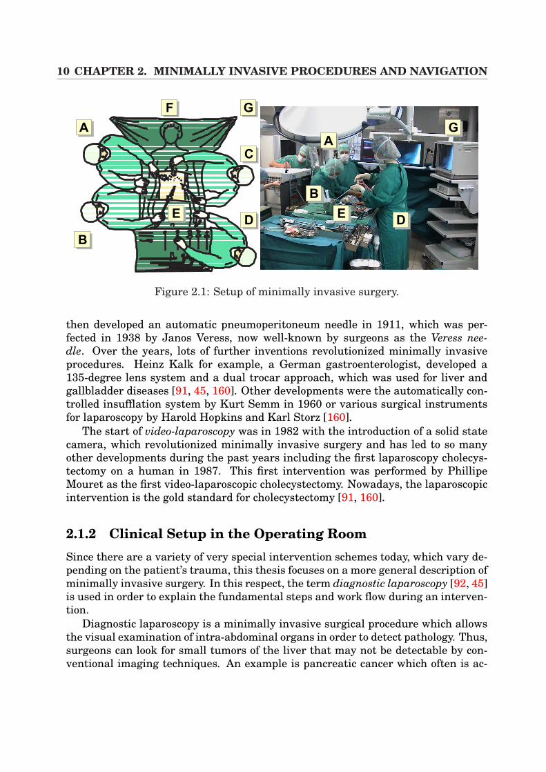
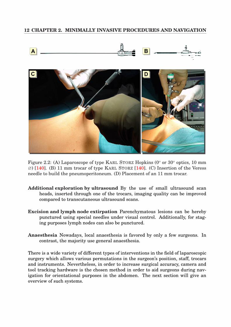
In general, after the insertion of a laparoscope (Figure 2.2 (A)) into the abdomenusing a trocar (Figure 2.2 (B)(D)), the laparoscopic 2D video images display a viewon a monitor of different surgical scenarios such as the liver, spleen, stomach, pan-creas, gallbladder, peritoneum, lymph nodes, and pelvis3. In Figure 2.1, an exam-ple of a surgical procedure is illustrated, showing the position of the medical teamand the necessary hardware during an intervention (here a setup of a laparoscopiccholecystectomy, but the final positions depend on the surgeon’s preferences). Thelegends (A) and (C) represent the surgeon’s assistants, (B) is the surgeon himselfand (D) denotes the people who are responsible for the instruments. In addition,the legends (F) and (G) indicate the anaesthesia station and the endoscopic tower,including video system and insufflation devices. The image to the right shows a realintervention scenario in the operation room (OR).
In order to perform a diagnostic laparoscopy Detter and Feussner [45] proposethe following steps:
Generation of the pneumoperitoneum The pneumoperitoneum is created us-ing a Veress needle (Figure 2.2 (C)). Here, carbon dioxide (CO2), insufflatedinto the abdomen on average 8-12 mmHg, is the preferred gas if diagnosticlaparoscopy is performed under general anaesthesia.
Positioning of the trocar After the generation of the pneumoperitoneum, thefirst trocar with an 11 mm diameter is inserted (Figure 2.2 (B)).
Inspection of the abdomen The abdomen now can be inspected at a certain se-quence in terms of the abdominal regions. Then, the second trocar with 5 mmcan be inserted.
Lavage for cytology In the case of unclear abdominal processes (e.g. the patientis suspected of having a malignant tumor), cytological analysis can be per-formed.
Regional exploration Depending on the patient’s disease additional trocars haveto be inserted in order to explore the region of interest. This includes the usageof additional instrumental tools.
3This list is non-exhaustive and contains only a small extract of many further surgical possibili-ties.
12 CHAPTER 2. MINIMALLY INVASIVE PROCEDURES AND NAVIGATION
AA AB
AC AD
Figure 2.2: (A) Laparoscope of type KARL STORZ Hopkins (0o or 30o optics, 10 mm∅) [140]. (B) 11 mm trocar of type KARL STORZ [140]. (C) Insertion of the Veressneedle to build the pneumoperitoneum. (D) Placement of an 11 mm trocar.
Additional exploration by ultrasound By the use of small ultrasound scanheads, inserted through one of the trocars, imaging quality can be improvedcompared to transcutaneous ultrasound scans.
Excision and lymph node extirpation Parenchymatous lesions can be herebypunctured using special needles under visual control. Additionally, for stag-ing purposes lymph nodes can also be punctured.
Anaesthesia Nowadays, local anaesthesia is favored by only a few surgeons. Incontrast, the majority use general anaesthesia.
There is a wide variety of different types of interventions in the field of laparoscopicsurgery which allows various permutations in the surgeon’s position, staff, trocarsand instruments. Nevertheless, in order to increase surgical accuracy, camera andtool tracking hardware is the chosen method in order to aid surgeons during nav-igation for orientational purposes in the abdomen. The next section will give anoverview of such systems.
2.2. NAVIGATION IN IMAGE-GUIDED SURGERY 13
2.2 Navigation in Image-Guided SurgeryThe triumphant advance of navigation systems is no longer limited to systems usedin cars. This relatively new principle also encompasses modern operating roomswhere sender and receiver components are also used to ease the orientation withinthe patient’s body. The reason for this immense advance is that navigational ortracking systems link human and instrument motions with computer-graphics ap-plications. In addition, they make interaction possible by tracking head, hand, bodyand instrument movements and instantly making this data available for controllinggraphics applications, which make use of it. In this way those navigation systemsbridge the gap between human motions and computer actions.
In consequence, there is a wide variety of graphical applications not only in med-ical applications that directly process the positional and orientational informationprovided by such systems consisting of a sender and receiver component. The follow-ing contains a reduced list of the far-reaching areas where navigational hardware isbrought into play:
• Full-body capture of human motions for animating 3D computer characters forlive performance animation.
• Helmet-mounted target-acquisition systems in tactical aircraft and vehicles.
• Head, hand and body tracking in virtual reality games and experiences.
• Real-time interaction with virtual images for design, prototyping and visual-ization.
• Measurement (localization) of medical instruments, probes, needles, endo-scopes etc. for controlling imaged-guided procedures.
• Head tracking in augmented reality systems.
• Tracking of ultrasound scan heads for 3D reconstruction of 2D image slices.
• Bio-mechanical measurement of anatomical parts and human motions ordiagnostic, intervention, and therapy purposes.
This doctoral thesis focuses on the area of medical applications where navigation isbecoming more and more important. In this area, surgeons make use of the newimaging modalities like the spiral-multi-slice CT and match the imaging space andthe patient space with different registration techniques. Navigation hardware thenmakes it possible to track the surgical tool for intra-operative navigation.
Navigation systems are of wide variety and can mainly be divided into track-ers that apply image analysis, electro-mechanic trackers, optical trackers, electro-magnetic trackers and robotic trackers [56].
14 CHAPTER 2. MINIMALLY INVASIVE PROCEDURES AND NAVIGATION
p= , ,[x y zc c c]T
xc
xcxLzc
pL L L=[ ]x yT
,xR
fl
b
xL
pL
Camera L
Camera R
xc
xcxp
zcxp
fl
fl
zc
AA AB
p= , ,[x y zc c c]T
pp p p=[ ]x yT
,
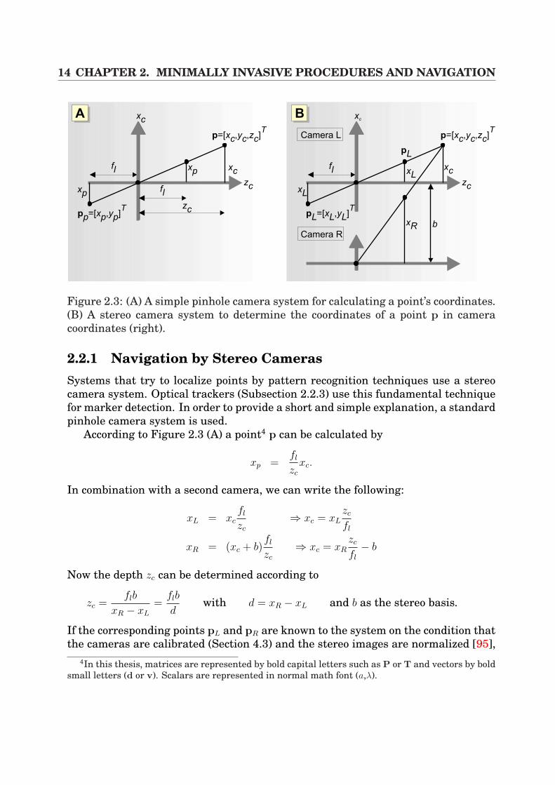
Figure 2.3: (A) A simple pinhole camera system for calculating a point’s coordinates.(B) A stereo camera system to determine the coordinates of a point p in cameracoordinates (right).
2.2.1 Navigation by Stereo CamerasSystems that try to localize points by pattern recognition techniques use a stereocamera system. Optical trackers (Subsection 2.2.3) use this fundamental techniquefor marker detection. In order to provide a short and simple explanation, a standardpinhole camera system is used.
According to Figure 2.3 (A) a point4 p can be calculated by
xp =fl
zc
xc.
In combination with a second camera, we can write the following:
xL = xcfl
zc
⇒ xc = xLzc
fl
xR = (xc + b)fl
zc
⇒ xc = xRzc
fl
− b
Now the depth zc can be determined according to
zc =flb
xR − xL
=flb
dwith d = xR − xL and b as the stereo basis.
If the corresponding points pL and pR are known to the system on the condition thatthe cameras are calibrated (Section 4.3) and the stereo images are normalized [95],
4In this thesis, matrices are represented by bold capital letters such as P or T and vectors by boldsmall letters (d or v). Scalars are represented in normal math font (a,λ).
2.2. NAVIGATION IN IMAGE-GUIDED SURGERY 15
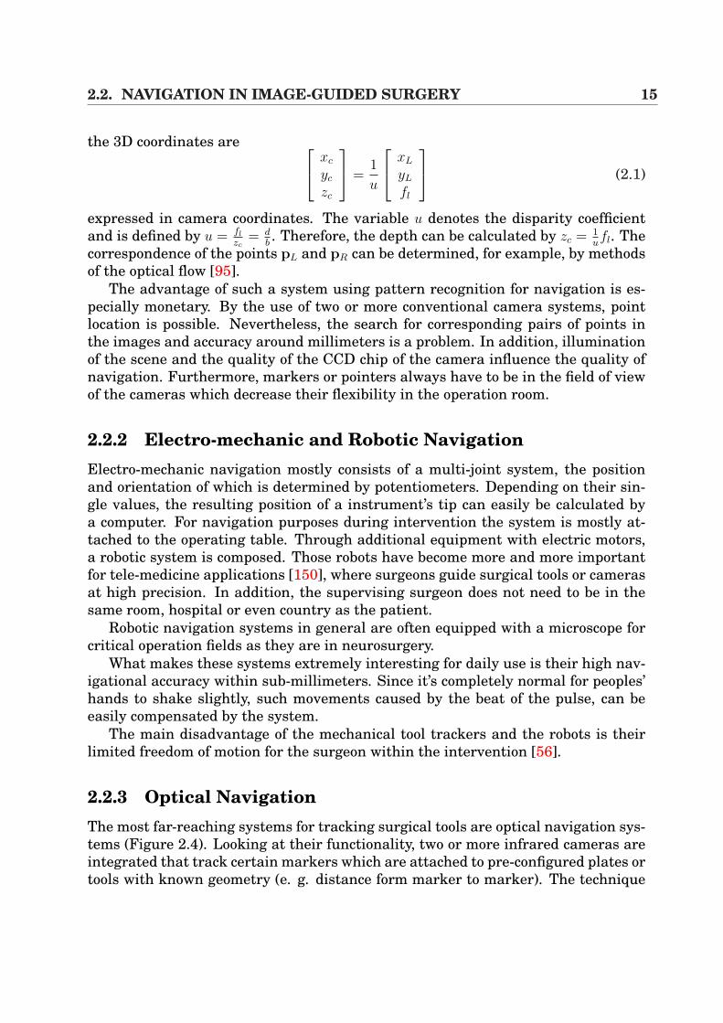
the 3D coordinates are
xc
yc
zc
=
1
u
xL
yL
fl
(2.1)
expressed in camera coordinates. The variable u denotes the disparity coefficientand is defined by u = fl
zc= d
b. Therefore, the depth can be calculated by zc = 1
ufl. The
correspondence of the points pL and pR can be determined, for example, by methodsof the optical flow [95].
The advantage of such a system using pattern recognition for navigation is es-pecially monetary. By the use of two or more conventional camera systems, pointlocation is possible. Nevertheless, the search for corresponding pairs of points inthe images and accuracy around millimeters is a problem. In addition, illuminationof the scene and the quality of the CCD chip of the camera influence the quality ofnavigation. Furthermore, markers or pointers always have to be in the field of viewof the cameras which decrease their flexibility in the operation room.
2.2.2 Electro-mechanic and Robotic NavigationElectro-mechanic navigation mostly consists of a multi-joint system, the positionand orientation of which is determined by potentiometers. Depending on their sin-gle values, the resulting position of a instrument’s tip can easily be calculated bya computer. For navigation purposes during intervention the system is mostly at-tached to the operating table. Through additional equipment with electric motors,a robotic system is composed. Those robots have become more and more importantfor tele-medicine applications [150], where surgeons guide surgical tools or camerasat high precision. In addition, the supervising surgeon does not need to be in thesame room, hospital or even country as the patient.
Robotic navigation systems in general are often equipped with a microscope forcritical operation fields as they are in neurosurgery.
What makes these systems extremely interesting for daily use is their high nav-igational accuracy within sub-millimeters. Since it’s completely normal for peoples’hands to shake slightly, such movements caused by the beat of the pulse, can beeasily compensated by the system.
The main disadvantage of the mechanical tool trackers and the robots is theirlimited freedom of motion for the surgeon within the intervention [56].
2.2.3 Optical NavigationThe most far-reaching systems for tracking surgical tools are optical navigation sys-tems (Figure 2.4). Looking at their functionality, two or more infrared cameras areintegrated that track certain markers which are attached to pre-configured plates ortools with known geometry (e. g. distance form marker to marker). The technique
16 CHAPTER 2. MINIMALLY INVASIVE PROCEDURES AND NAVIGATION
AA AB
AC AD
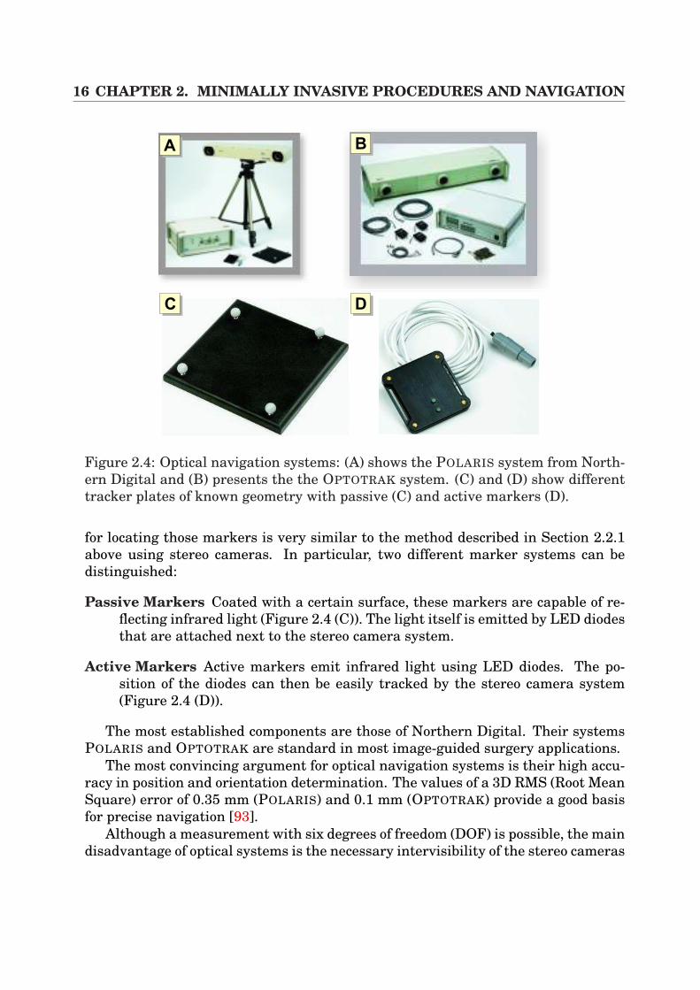
Figure 2.4: Optical navigation systems: (A) shows the POLARIS system from North-ern Digital and (B) presents the the OPTOTRAK system. (C) and (D) show differenttracker plates of known geometry with passive (C) and active markers (D).
for locating those markers is very similar to the method described in Section 2.2.1above using stereo cameras. In particular, two different marker systems can bedistinguished:
Passive Markers Coated with a certain surface, these markers are capable of re-flecting infrared light (Figure 2.4 (C)). The light itself is emitted by LED diodesthat are attached next to the stereo camera system.
Active Markers Active markers emit infrared light using LED diodes. The po-sition of the diodes can then be easily tracked by the stereo camera system(Figure 2.4 (D)).
The most established components are those of Northern Digital. Their systemsPOLARIS and OPTOTRAK are standard in most image-guided surgery applications.
The most convincing argument for optical navigation systems is their high accu-racy in position and orientation determination. The values of a 3D RMS (Root MeanSquare) error of 0.35 mm (POLARIS) and 0.1 mm (OPTOTRAK) provide a good basisfor precise navigation [93].
Although a measurement with six degrees of freedom (DOF) is possible, the maindisadvantage of optical systems is the necessary intervisibility of the stereo cameras
2.2. NAVIGATION IN IMAGE-GUIDED SURGERY 17
AA AB
AC AD AE
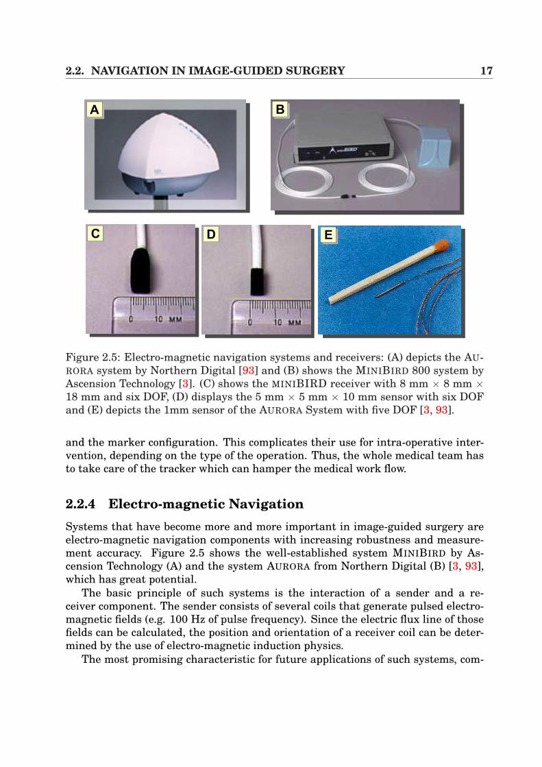
Figure 2.5: Electro-magnetic navigation systems and receivers: (A) depicts the AU-RORA system by Northern Digital [93] and (B) shows the MINIBIRD 800 system byAscension Technology [3]. (C) shows the MINIBIRD receiver with 8 mm × 8 mm ×18 mm and six DOF, (D) displays the 5 mm × 5 mm × 10 mm sensor with six DOFand (E) depicts the 1mm sensor of the AURORA System with five DOF [3, 93].
and the marker configuration. This complicates their use for intra-operative inter-vention, depending on the type of the operation. Thus, the whole medical team hasto take care of the tracker which can hamper the medical work flow.
2.2.4 Electro-magnetic NavigationSystems that have become more and more important in image-guided surgery areelectro-magnetic navigation components with increasing robustness and measure-ment accuracy. Figure 2.5 shows the well-established system MINIBIRD by As-cension Technology (A) and the system AURORA from Northern Digital (B) [3, 93],which has great potential.
The basic principle of such systems is the interaction of a sender and a re-ceiver component. The sender consists of several coils that generate pulsed electro-magnetic fields (e.g. 100 Hz of pulse frequency). Since the electric flux line of thosefields can be calculated, the position and orientation of a receiver coil can be deter-mined by the use of electro-magnetic induction physics.
The most promising characteristic for future applications of such systems, com-
18 CHAPTER 2. MINIMALLY INVASIVE PROCEDURES AND NAVIGATION
pared to optical ones, is that there is no necessary intervisibility between the senderand receiver components. This eases the handling of electro-magnetic trackers im-mensely, especially for intra-operative guidance. Since the dimensions of the re-ceiver components have been greatly minimized in recent years (1 mm, AURORA, 5DOF), their application in endoscopic interventions is of high interest, because thecoil can be inserted into the endoscope’s working tube (Figure 2.5 (C)(D)(E)).
Although these systems are very promising for the future, some drawbacks incomparison with optical trackers have to be mentioned. According to the mea-surement accuracy values around 1.8 mm of RMS has to be accepted compared to0.35 mm RMS with optical trackers [3, 93]. Furthermore, since electro-magneticfields are the principles the system is based on, metallic tools can have immense in-fluence on the location accuracy [13, 52], which makes the application to precision-based interventions (e.g in neuronavigation) rather difficult. Furthermore, sinceelectro-magnetic systems have a restricted location volume, the position of thesender component has to be close to the medical point of interest in order to avoidmeasurement errors during intra-operative use.
2.2.5 ApplicationsAlthough the basic techniques of intra-operative navigation has been improved im-mensely in recent years, well established medical applications using that techniqueare mostly restricted to only a few clinical fields. A very brief list of establishedclinical fields are discussed below.
Neuronavigation A pre-operative CT/MR scan, magneto-enzephalography orfunctional MRI is used for path planning purposes in order to cut tumors,aneurysms or epilepsy processes. The difficulty consists of the fact that resec-tions of lesions in eloquent areas bear the risk of post-operative functional im-pairment. In order to reduce the surgical trauma, navigational help is used forexact intra-operative orientation within the patient. In conjunction with reg-istration methods (mostly rigid) of pre-operative and intra-operative volumes,path planning or functional information can be transferred to a microscopesystem (e.g. Zeiss MKM) for precise navigation using overlay techniques. Be-cause of the brain shift phenomenon, registration errors occur, which is of highinterest in research [156, 68, 71].
Total hip replacement and osseous applications There are many conditionsthat can result in the degeneration of the hip joint. There is osteoarthritis,avascular necrosis or fractures of the hip which force the surgeon to replace thepainful joint. During surgery, a prosthesis is inserted consisting of the femoraland the acetabular component. In this context, different systems try to aid sur-geons intra-operatively for navigation purposes. The ROBODOC system forexample has been applied in clinical use since 1992 and merges pre-operative

2.2. NAVIGATION IN IMAGE-GUIDED SURGERY 19
planning, based on CT, with the precise robotic machining of the bone [7, 142].Very similar to that is the CASPAR system for knee surgery [100]. Furtherapplications are also well-known in oral and maxillofacial surgery[132].
In Part II, electro-magnetic navigation is used as the basis for tracking surgicaltools and cameras. The above mentioned guidance information is applied to image-overlay systems.

20 CHAPTER 2. MINIMALLY INVASIVE PROCEDURES AND NAVIGATION

Part II
Fusion of Video and TomographicImages

22
Chapter 3
Volume Rendering
Recently, in the area of computer graphics, several approaches have been publishedin the context of volume rendering that range from pure software solutions [36,66, 154, 76] to general purpose [19, 17, 152, 86, 109] or special purpose [101, 87]hardware-accelerated techniques. This chapter deals with the topic of direct volumerendering in combination with medical 3D scalar fields on uniform grids. Voxel datais directly visualized applying an underlying emission-absorption model which iscontrary to indirect methods that exploit the volume’s content by the extraction ofisosurfaces such as the marching cubes algorithm [79].
In Section 3.1, a fundamental outline of direct volume rendering approaches isdescribed, including the Raycasting algorithm and the Shear-Warp-Factorization.Section 3.2 introduces the possibilities of graphics hardware in terms of directvolume rendering in respect of rendering basics. The terms vertex shader andpixel/fragment shader are introduced. Then in Section 3.3 the basics of 3D texture-based approaches are described whilst Section 3.4 deals with the techniques ofmulti-texture-based direct volume rendering with programmable graphics hard-ware. Section 3.5 contains a conclusion. In addition, this chapter is fundamentalfor Chapter 6 that presents interactive volume deformation techniques, based ongraphics hardware and pixel shader techniques.
3.1 Direct Volume RenderingDirect volume rendering approaches map the scalar value of each sample point tophysical quantities, describing the emission (color) and the absorption (opacity) oflight. This mapping, also called classification, can be realized by the use of a so-called transfer function [108] that has to be set by the user. Direct volume methodscan be divided into the following main groups:
Image-order techniques Taking into account every pixel on the image plane, aray is sent into the volume data, and the final color of a pixel is calculated byintegrating the emission/absorption values of each voxel that is hit by the ray.
24 CHAPTER 3. VOLUME RENDERING
The classic example is the ray-casting algorithm. Here, the pixel’s color valueis defined by equidistantly resampling the volume along the ray using inter-polation and by mapping those values to emission-absorption coefficients [60].Examples of standard implementations of such algorithms are the works pro-posed by Kajiya et al. [66] and Drebin et al. [36]. For acceleration purposes,Kajiya et al. [66] used the early-ray termination that aborts the integrationof emission/absorption values when the opacity reaches a value of one. Otherexamples for acceleration techniques are space-leaping [32], which excludesempty voxels during integration and hierarchical methods that progressivelysubdivide the volume while rays are sent through the volume [77, 157]. Al-though ray casting techniques are the chosen method for high quality images,computational costs caused by the large number of necessary interpolationsfor volume resampling make those approaches impracticable for high perfor-mance volume rendering at high frame rates.
Object-order techniques In contrast to image-order algorithms, object-ordertechniques start in object space and calculate a single voxel’s contribution toa pixel on the image plane in recursive order. A famous example of this tech-nique is the Splatting-Algorithm proposed by Westover et al. [154], where eachvoxel is interpreted as a radially symmetric kernel which is projected onto theimage plane.A hybrid form of image-order and object-order techniques is the shear-warpfactorization proposed by Lacroute et al. [76]. The viewing transformation isdecomposed into a shear transformation in 3D, a projective mapping leadingto a distorted intermediate image and a final 2D warping step for calculatingthe correct resulting image. In order to allow for perspective projection, an ad-ditional scaling of the image slices has to be introduced. Although this methodreduces the interpolation from trilinear to bilinear, a drawback is the need forthree copies of the volume in memory, one slice stack for each slicing direction.Depending on the angle between viewing direction and slicing normal, the cor-rect slice stack has to be permutated. In the following sections, those basicideas are adopted in the context of hardware-based volume rendering.
Frequency domain techniques By the use of these techniques, the volume istransformed in frequency domain using a 3D Fourier transformation [82] in apreprocessing step. Then, a resulting 2D image is generated by the extractionof a slice image in the frequency domain and by the application of a inverse2D Fourier transformation. Although the computational complexity is favor-able, only the viewing direction can be modified interactively in the context ofdisplay parameters.
Summing up, although image-order techniques are the chosen methods in the con-text of image quality, they require immensely computational costs in order to cal-culate a final projection image. In contrast, while frequency domain techniques are
3.2. BASICS OF GRAPHICS HARDWARE 25
Vertex Data
Transform &Lighting
ProgrammableVertex Shader
Clipping
Viewport Transform
Ge
om
etr
yP
roc
es
sin
g
Triangle Setup
Texture-Stages ProgrammablePixel Shader
Fog BlendingVisibility
Frame Buffer
Ra
ste
riza
tio
n
Figure 3.1: The graphics pipeline.
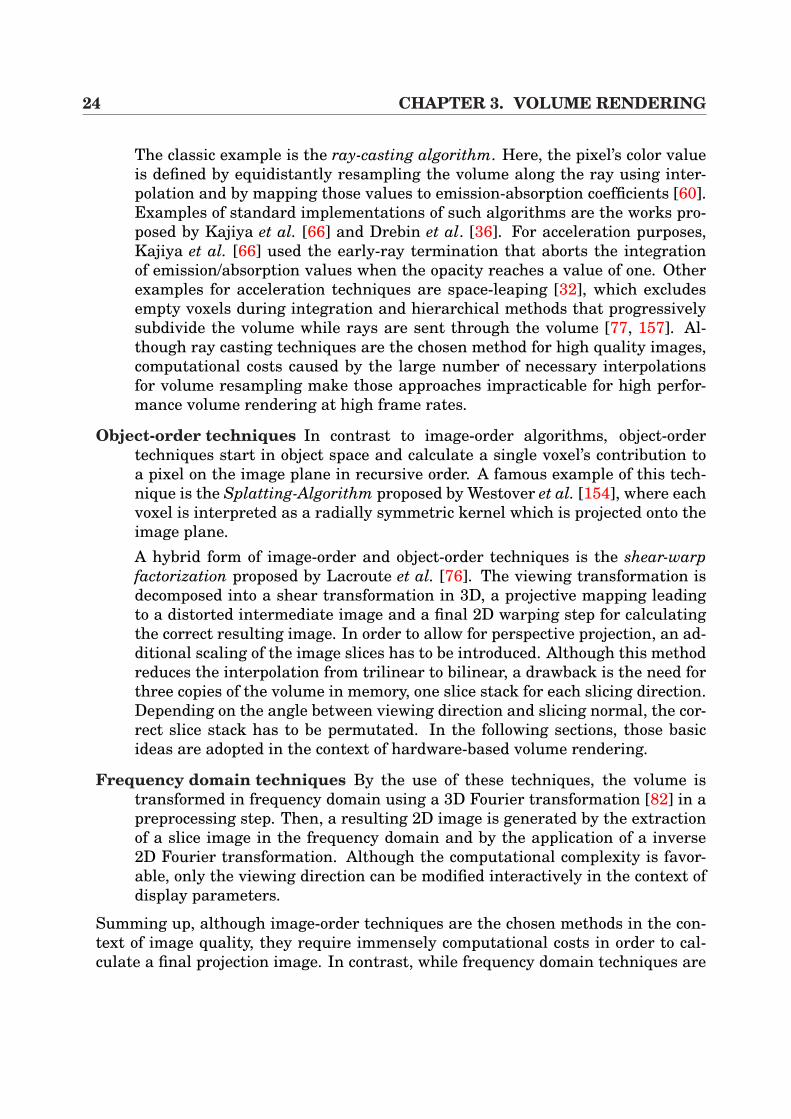
favorable in terms of computational complexity, only a reduced set of display pa-rameters can be modified. Since we want to perform an image overlay system atinteractive frame rates and high image quality, we will adopt the basic idea of thehybrid shear-warp factorization in order to introduce hardware acceleration.
3.2 Basics of Graphics HardwareThis section contains a basic outline of the graphics pipeline on the graphics adapterwhich processes incoming vertex streams. Since this topic is worth mentioning ina separate work, only a very general overview of the mechanisms is given. In Fig-
26 CHAPTER 3. VOLUME RENDERING
Fragmentcolor inputto texturing
Texture unit 0with
texture image 0
Texture unit 1with
texture image 1
Fragmentcolor output
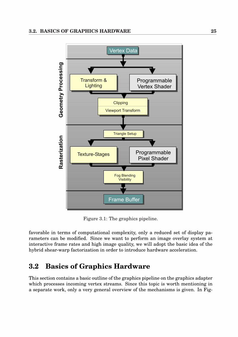
after texturing
Figure 3.2: Multi-texturing: different texture units are used in order to compose theproperties of a fragment during one rendering pass.
ure 3.1 the elementary steps of the graphics pipeline are illustrated [2]. Here, anincoming stream of vertices of an application is processed and passed to the Ge-ometry Processing Unit where the Model & View-Transformation of each vertex iscalculated in a first step, which determines the position of a vertex in a scene. Inaddition, the lighting properties of a vertex has to be calculated for realistic effects.Traditionally, these transformations have been composed by the hard-wired trans-form and lighting model on the graphics adapter, also referred to as fixed functionpipeline. Thus, for example the programmer was forced to use the Gouraud/Phongmodel for lighting. Nevertheless, recent graphics adapters (NVidia GeForce, ATIRadeon) provide more flexibility which allows the user to develop his own vertexshader programs for vertex transformation and lighting. The traditional functionscan then be switched off and replaced by user-specific shaders. Those programs,evaluated by the graphics adapter, are stored in the form of an assembly language,through macros or higher level languages. Examples are the possibility of proce-dural deformations and more elaborated per-vertex lighting models that offer newfeatures for the future in terms of realism and performance. A detailed outline ofvertex shaders is presented in [2].
After the clipping and viewport mapping, the resulting set of geometric primi-tives1) enters the Rasterization Stage, which decomposes the primitives into theirelements (fragments) to pixel values of the frame buffer. Of great importance inthis context is the texture stage. If a polygon is assigned to a texture image, thepolygon is rasterized and the corresponding texture is applied in order to determinethe fragments’ properties (e.g. color) according to the the per-fragment operations(alpha test, stencil test, depth test, alpha blending) [108]. In combination with thetechnique of multi-texturing, which allows the assignment of one polygon to severaltextures, it is possible to combine different texture units to determine the resultingproperties of an image pixel. During one rendering pass, the values of a textureunit are used in combination with the following texture units, depending only on
1Vertices are composed to primitives.
3.3. STANDARD 3D-TEXTURES 27
AA AB AC
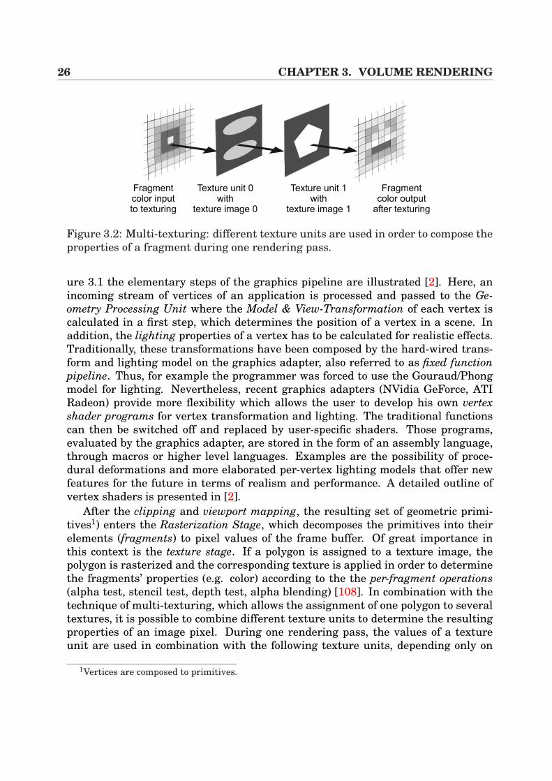
Figure 3.3: 3D texture-based volume rendering: (A) The bounding box of the volumeis sliced by the use of viewport-aligned polygons. (B) Since the volume is representedwith a 3D texture, slicing polygons are filled by trilinear interpolation in hardware.(C) Final image of a liver. (Source of volume: MITI, TU Munich).
the number of texture units (cf. Figure 3.2).Nevertheless, although the standard texture-stage is of fixed type on the graph-
ics adapter, users of new product releases of graphics adapters can completely by-pass this stage and choose the Programmable Pixel/Fragment Shader as an alter-native pipeline path. Similar to vertex shading programs, a flexible way is providedwith more possibilities to exploit hardware effects. Thus, data can be processed bythe use of constants, a number of texture address instructions to route various dataand by a set of arithmetic instructions. The output of one texture unit can be routedto be the input of an other texture unit including different arithmetic operations.The classic examples of such pixel shaders are the NVidia register combiners [96]and the ATI fragment shaders [1], which allow the realization of pixel shading via aconvenient OpenGL API. Similarly, the possibilities can be exploited by DirectX.
For our purposes in the context of volume rendering, trilinear interpolation of 2Dtexture-based volume rendering (Sections 3.4) and 3D dependent texture lookups forvolume deformation (Chapter 6) is performed by the use of pixel shader techniques.
3.3 Standard 3D-TexturesDirect volume rendering by the use of 3D textures has been introduced by Cabral etal. [19]. With this technique, the volume is stored within a 3D texture on the graph-ics adapter. Whenever the camera view changes, viewport-aligned slices betweenthe volume’s bounding box and the image plane at different depth values are cal-culated (Figure 3.3), whereas the filling of the slicing polygons is determined bytrilinear interpolation in hardware. After this these filled slices are blended inback-to-front order to generate the final image. Although high image quality canbe performed by exploiting the graphics adapter’s capabilities, the drawback of the
28 CHAPTER 3. VOLUME RENDERING
texture 0texture 0
texture 0texture 1
slice i
slice i+1
RGB A co
mb
ine
r
RGB A
fragment ofintermediate
slice
slice i
slice i+1
ACAA AB
RGB A
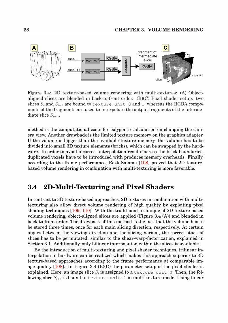
Figure 3.4: 2D texture-based volume rendering with multi-textures: (A) Object-aligned slices are blended in back-to-front order. (B)(C) Pixel shader setup: twoslices Si and Si+1 are bound to texture unit 0 and 1, whereas the RGBA compo-nents of the fragments are used to interpolate the output fragments of the interme-diate slice Si+α.
method is the computational costs for polygon recalculation on changing the cam-era view. Another drawback is the limited texture memory on the graphics adapter.If the volume is bigger than the available texture memory, the volume has to bedivided into small 3D texture elements (bricks), which can be swapped by the hard-ware. In order to avoid incorrect interpolation results across the brick boundaries,duplicated voxels have to be introduced with produces memory overheads. Finally,according to the frame performance, Rezk-Salama [108] proved that 2D texture-based volume rendering in combination with multi-texturing is more favorable.
3.4 2D-Multi-Texturing and Pixel Shaders
In contrast to 3D texture-based approaches, 2D textures in combination with multi-texturing also allow direct volume rendering of high quality by exploiting pixelshading techniques [109, 110]. With the traditional technique of 2D texture-basedvolume rendering, object-aligned slices are applied (Figure 3.4 (A)) and blended inback-to-front order. The drawback of this method is the fact that the volume has tobe stored three times, once for each main slicing direction, respectively. At certainangles between the viewing direction and the slicing normal, the correct stack ofslices has to be permutated, similar to the shear-warp-factorization, explained inSection 3.1. Additionally, only bilinear interpolation within the slices is available.
By the introduction of multi-texturing and pixel shader techniques, trilinear in-terpolation in hardware can be realized which makes this approach superior to 3Dtexture-based approaches according to the frame performance at comparable im-age quality [108]. In Figure 3.4 (B)(C) the parameter setup of the pixel shader isexplained. Here, an image slice Si is assigned to a texture unit 0 . Then, the fol-lowing slice Si+1 is bound to texture unit 1 in multi-texture mode. Using linear
3.5. CONCLUSION 29
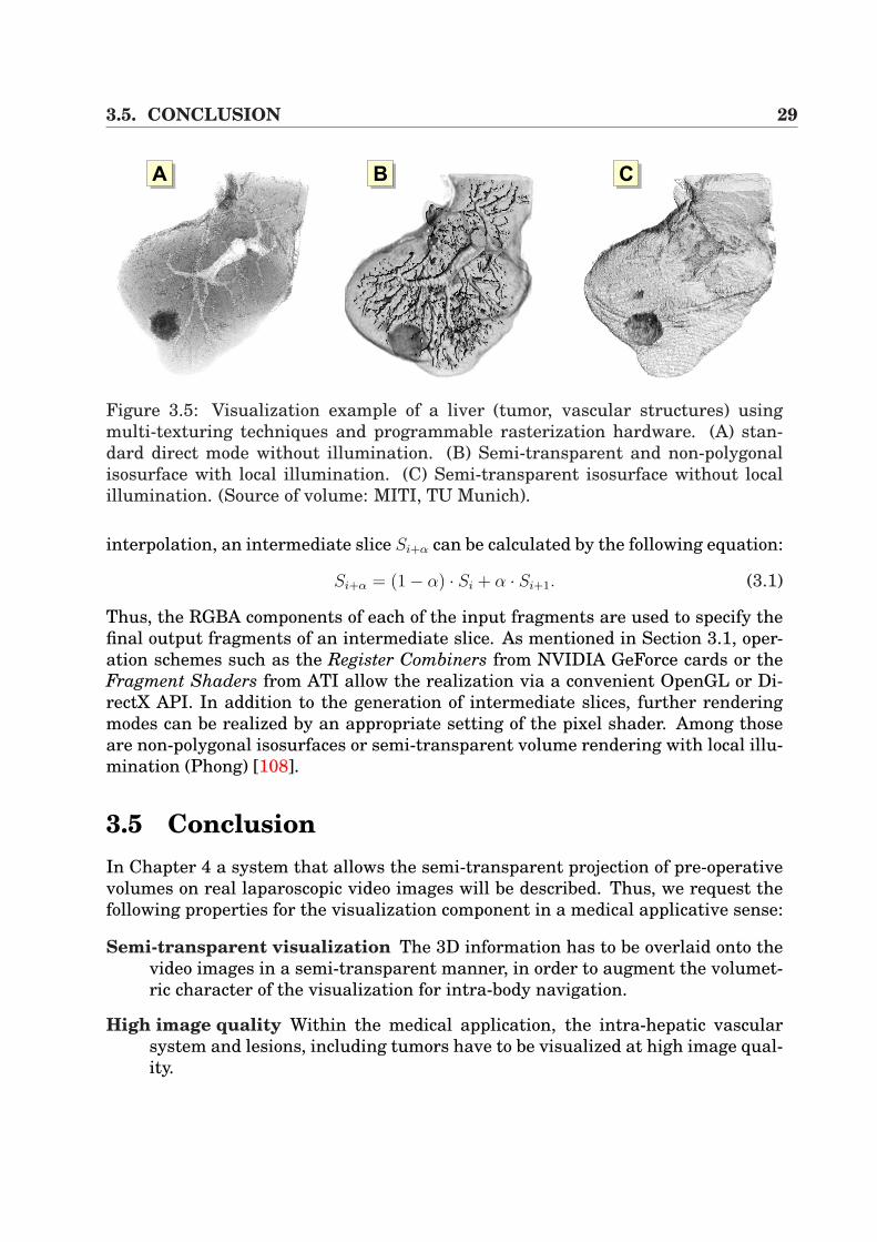
AA AB AC
Figure 3.5: Visualization example of a liver (tumor, vascular structures) usingmulti-texturing techniques and programmable rasterization hardware. (A) stan-dard direct mode without illumination. (B) Semi-transparent and non-polygonalisosurface with local illumination. (C) Semi-transparent isosurface without localillumination. (Source of volume: MITI, TU Munich).
interpolation, an intermediate slice Si+α can be calculated by the following equation:
Si+α = (1− α) · Si + α · Si+1. (3.1)
Thus, the RGBA components of each of the input fragments are used to specify thefinal output fragments of an intermediate slice. As mentioned in Section 3.1, oper-ation schemes such as the Register Combiners from NVIDIA GeForce cards or theFragment Shaders from ATI allow the realization via a convenient OpenGL or Di-rectX API. In addition to the generation of intermediate slices, further renderingmodes can be realized by an appropriate setting of the pixel shader. Among thoseare non-polygonal isosurfaces or semi-transparent volume rendering with local illu-mination (Phong) [108].
3.5 ConclusionIn Chapter 4 a system that allows the semi-transparent projection of pre-operativevolumes on real laparoscopic video images will be described. Thus, we request thefollowing properties for the visualization component in a medical applicative sense:
Semi-transparent visualization The 3D information has to be overlaid onto thevideo images in a semi-transparent manner, in order to augment the volumet-ric character of the visualization for intra-body navigation.
High image quality Within the medical application, the intra-hepatic vascularsystem and lesions, including tumors have to be visualized at high image qual-ity.
30 CHAPTER 3. VOLUME RENDERING
Interactivity Since the virtual view has to be permanently adapted to the sur-geon’s view at the time of intervention, a visualization at real-time frame rateshas to be applied.
Therefore, according to these demands, the visualization system, presented inthe previous section, is the chosen component. In Figure 3.5 the visualization of aliver is displayed, showing the vascular system and a tumor. In combination withmulti-texturing and pixel shader techniques, it is possible to generate images whichare suitable for intra-operative use.
Since performance measurements are only valid in the context of the whole sys-tem, the results in terms of frame performance are presented in Section 4.6, takinginto account all components of the system.
Chapter 4
Augmented Reality -Rigid Fusion of Tomographic Dataand Volume Rendering
4.1 IntroductionWhat does Augmented Reality mean? ”An Augmented Reality (AR) system supple-ments the real world with virtual (computer-generated) objects that appear to coexistin the same space as the real world” [4].
To be more precise, the authors Azuma et al. [4] request the following propertiesfor AR systems:
• AR combines the real and the corresponding virtual objects in a real environ-ment setup.
• AR runs interactively and in real-time.
• AR registers real and virtual objects with each other.
Mixed Reality
VirtualEnvironment
AugmentedVirtuality
AugmentedReality
RealEnvironment
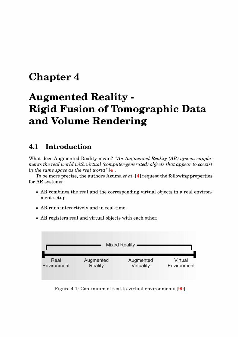
Figure 4.1: Continuum of real-to-virtual environments [90].
32 CHAPTER 4. AUGMENTED REALITY - FUSION OF CT AND VR
Milgram et al. [90] present a continuum of real-to-virtual environments in an ex-tended manner in order to explain this topic (Figure 4.1). Here, AR systems arepart of the mixed reality, but must be distinguished from Augmented Virtualitywhere real objects are added to virtual environments in contrast to AR with realenvironments and virtual objects.
The beginning of AR dates back to the 1960s to the work of Sutherland [141]who utilized a head mounted display (HMD) for the presentation of 3D graphics.Over the decades the applications for VR systems has expanded rapidly with in-creasing advances in display and visualization techniques. Today, the main fieldsof application are medical visualization, maintenance and repair of complex equip-ment, annotation, and path planning [4].
This chapter focuses on medical visualization, in particular on video overlay sys-tems for laparoscopic or endoscopic intervention schemes. Compared to many otherapplications the difficulty for intra-operative use is based on the operative envi-ronment. When designing and implementing such a system, the special hardwareand software components have to be adapted to surgeon’s wishes and ergonomic re-quests. Thus, it is the aim to build an ARS for minimally invasive liver interventionsthat influences the surgeon’s usual environment as little as possible. Additionallyin the age of cost effectiveness and reduced expenses in the Public Health System,it is the aim to find cheap solutions.
In our system, AR is presented based on camera calibration which is contrary toself-calibration [43] in order to determine the camera parameters. Moreover, self-calibration requires image processing for tracking marker points which is extremelycomplex on real laparoscopic image sequences, including large-scaled setups thathamper the medical work flow. Additionally, our system utilizes external (optic andelectro-magnetic) navigation for tracking the surgical camera and for registrationof the patient to the tomographic image space.
This chapter is divided into four main parts. In the following Section 4.2, someprevious works are presented in terms of image overlay and augmented reality formedical applications in combination with rigid registration techniques. Since ARsystems require the knowledge of camera parameters, the fundamentals of standardcamera calibration routines are introduced in Section 4.3. In addition, the sectionrefers to endoscopic calibration in terms of efficient distortion correction.
The implemented system applies external navigation systems for tracking thesurgical cameras or tools. This requires the fixation of the sensors onto those tools.Therefore, suitable routines for calibrating the sensor are discussed in Section 4.4,utilizing the so-called hand-eye calibration. Section 4.5 then describes the completeaugmentation system, bringing all components together using direct volume render-ing, external navigation and calibration for the intra-operative use. The technicalbasics of our system are described and Chapter 8 details the medical application inreal interventions. Section 4.7 contains a conclusion.
4.2. PREVIOUS WORK 33
4.2 Previous WorkImage overlay systems have often been used in different clinical setups or researchprojects. The first and most important use was in neurosurgical interventions. Sucha system was originally proposed by Kelly et al. [69] and furthered by Robertset al. [114]. Simple outlines or trajectories in one eyepiece have been overlaidwhich were extracted from pre-operative CT volumes. A similar work, also usingadditional visualization hardware to overlay the surgeon’s view, is presented byMasamune et al. [83]. Here the authors use a half-silvered mirror system withpre-operative 2D slicing data as overlay, whereas the display’s position is measuredwith a linear sensor. The registration between the patient and the pre-operativedata is performed by fiducial markers and rigid transformation (cf. Section 4.5).Very similar to this work is the project presented by Blackwell et al. [14], whichalso utilizes a standard flat panel liquid crystal display (LCD) with the back lightremoved. The visualization panel is tracked by the use of an optical navigationsystem (cf. Section 2.2). The overlay information is presented by 3D surface render-ings. The system presented by Salb et al. [117] uses a technique based on a binoc-ular stereoscopic see-through display with SVGA resolution (800 × 600 pixels) interms of a HMD. Birkfellner et al. [12, 11] propose the Varioscope, a light-weightedhead-mounted operating microscope used as a HMD. In addition, they utilize anoptical tracker, a triaxial gyroscope and an accelerometer for predictive filtering ofthe HMD’s position through a Kalman filter [67]. Photogrammetric registration ofthe readings from the optical tracker to the actual scene, detected by the cameras,is calculated by Tsai’s algorithm [144]. The visualization component for overlay onthe Varioscope uses surface renderings in OpenGL. A work which is strongly relatedto this is the work carried out by Sauer et al. [119]. Instead of optical tracking theyapply image processing-based algorithms for marker detection in order to track thecamera. This avoids jittering which occurs with navigation systems.
All the systems, detailed above, have been developed for head or osseous applica-tions. A fundamental prototype for augmented reality visualization in laparoscopyhas been developed at the University of North Carolina by Fuchs et al. [48] whichemploys an expensive 3D laparoscope, consisting of a projector for structured lightfor depth calculation and a standard laparoscope for observing the light pattern.The augmentation of the surgeon’s view is achieved by the use of an HMD, whichis tracked by an optical ceiling sensor. Unfortunately, the system was extremelylarge-scaled and impracticable for intra-operative use. Of similarity to this is thework proposed by Cash et al. [21]. They use a laser range scanner which generates adense point set of surface data of a liver phantom. In combination with the iterativeclosest point (ICP) algorithm [10], a point-based registration has been performedusing a surface of a liver phantom and an isosurface, extracted from the CT. Alsorelated are the works by Beasley et al. [8] and Herline et al. [63]. The differenceis the generation of the surfaces of the liver phantoms. A pointer attached to anoptical tracking sensor is moved along the liver to create a surface.
34 CHAPTER 4. AUGMENTED REALITY - FUSION OF CT AND VR
yW
xW
zW
World
Camera
zC
yC
xC
[ ]C CX Y,T
pI=[XT
f f,Y ]
p = xW w w w[ ],y ,zT
T
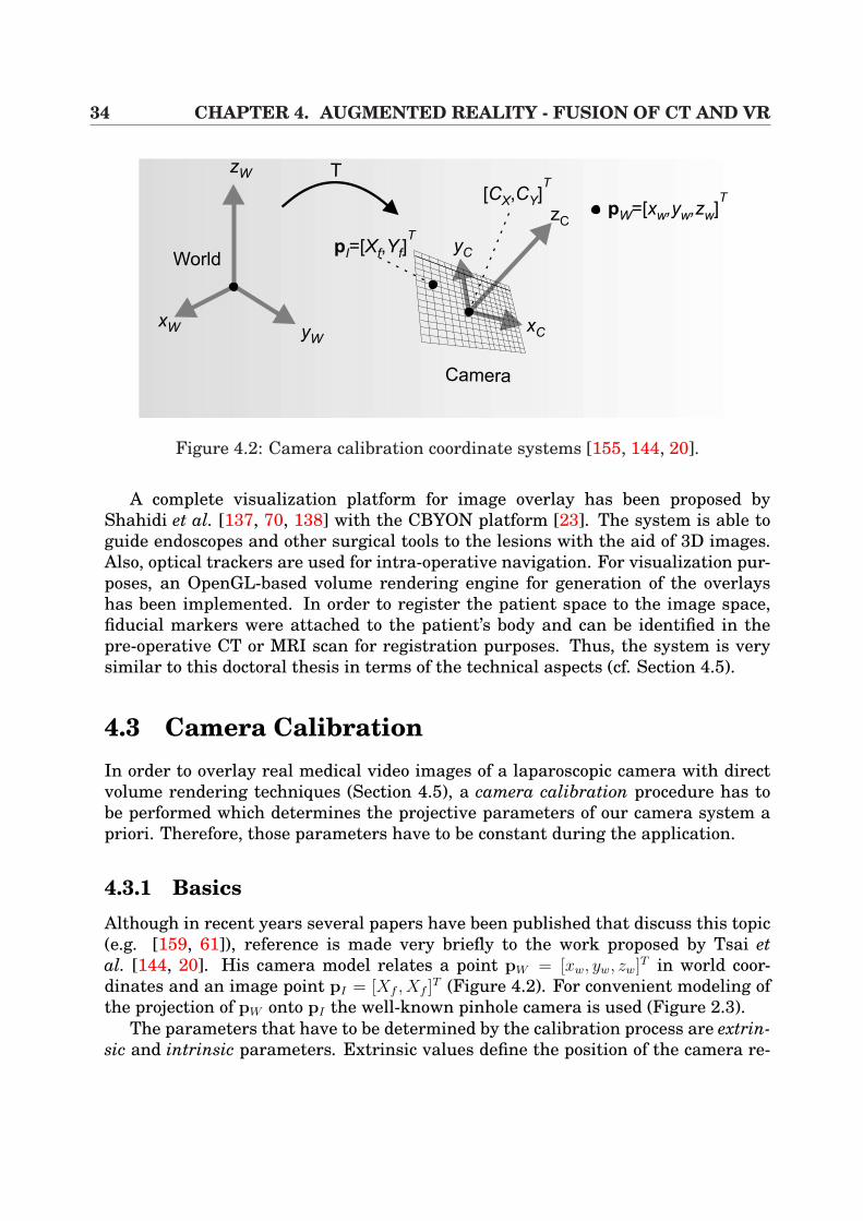
Figure 4.2: Camera calibration coordinate systems [155, 144, 20].
A complete visualization platform for image overlay has been proposed byShahidi et al. [137, 70, 138] with the CBYON platform [23]. The system is able toguide endoscopes and other surgical tools to the lesions with the aid of 3D images.Also, optical trackers are used for intra-operative navigation. For visualization pur-poses, an OpenGL-based volume rendering engine for generation of the overlayshas been implemented. In order to register the patient space to the image space,fiducial markers were attached to the patient’s body and can be identified in thepre-operative CT or MRI scan for registration purposes. Thus, the system is verysimilar to this doctoral thesis in terms of the technical aspects (cf. Section 4.5).
4.3 Camera CalibrationIn order to overlay real medical video images of a laparoscopic camera with directvolume rendering techniques (Section 4.5), a camera calibration procedure has tobe performed which determines the projective parameters of our camera system apriori. Therefore, those parameters have to be constant during the application.
4.3.1 BasicsAlthough in recent years several papers have been published that discuss this topic(e.g. [159, 61]), reference is made very briefly to the work proposed by Tsai etal. [144, 20]. His camera model relates a point pW = [xw, yw, zw]T in world coor-dinates and an image point pI = [Xf , Xf ]
T (Figure 4.2). For convenient modeling ofthe projection of pW onto pI the well-known pinhole camera is used (Figure 2.3).
The parameters that have to be determined by the calibration process are extrin-sic and intrinsic parameters. Extrinsic values define the position of the camera re-
4.3. CAMERA CALIBRATION 35
lated to the world coordinate system by translation and rotation (tx, ty, tz, φx, φy, φz).Each time the camera is moved, those parameters have to be recalculated, contraryto the intrinsic parameters that characterize the projective properties of the camera(fx, fy, Cx, Cy, κ1[, κ2, ...]). The variables fx and fy define the focal length, [Cx, Cy]
T
represents the center of the image in pixel coordinates and κi are the lens distor-tion coefficients. The model illustrated in [144] uses an additional parameter sx
that represents a scaling factor for the sensor’s rows of the CCD-chip. The followingtransformations have then to be considered:
[xw, yw, zw]T(1)
=⇒ [xc, yc, zc]T (2)
=⇒ [Xu, Yu]T (3)
=⇒ [Xd, Yd]T (4)
=⇒ [Xf , Yf ]T (4.1)
In the first transformation (1), object points are mapped from world to camera coor-dinate system using a rotation matrix R ∈ IR3×3 and a translation vector t, composedas a matrix T ∈ IR3×3 (homogeneous coordinate notation):
xc
yc
zc
1
=
[R t0T 1
]
xw
yw
zw
1
= T
xw
yw
zw
1
(4.2)
with t = [tx, ty, tz]T and R = φ(φx, φy, φz) ∈ IR3×3. In the following transformation
(2), points that are defined in the camera coordinate system are projected onto thecamera image plane, modelled by a normalized pinhole camera without any distor-tions [20]: [
Xu
Yu
]=
1
zc
[xc
yc
](4.3)
Afterwards (3), lens distortion is included for the undistorted image coordinates(Xu, Yu)
T . In [20] radial and tangential distortion modeling is considered using apolynomial of rd, which leads to the normalized coordinates (Xd, Yd)
T :[
Xd
Yd
]= (1 + κ1r
2d + κ2r
4d + κ5r
6d)
[Xu
Xu
]+
[2κ3XuYu + κ4(r
2d + 2X2
u)κ3(r
2d + 2Y 2
u ) + 2κ4XuYu
](4.4)
By the use of Equation 4.4 the final image point coordinates can be determined by
Xf
Yf
1
=
fx αfx Cx
0 fy Cy
0 0 1
Xd
Yd
1
(4.5)
It is apparent that the focal distances fx and fy also allow the modeling of non-square CCD arrays. The parameter α encodes the angle between the x and y sensoraxes [20]. The model described above is fundamental to different calibration tech-niques proposed in [159, 61, 155].
For camera calibration purposes, planar or coplanar calibration patterns are uti-lized (cf. Figure 4.3), whereas their markers or squares can then easily be detected
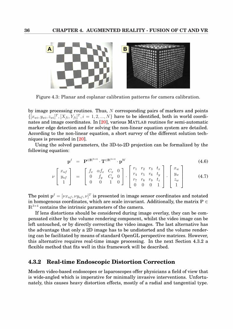
36 CHAPTER 4. AUGMENTED REALITY - FUSION OF CT AND VR
AA AB
Figure 4.3: Planar and coplanar calibration patterns for camera calibration.
by image processing routines. Thus, N corresponding pairs of markers and points[xwi, ywi, zwi]
T , [Xfi, Yfi]T , i = 1, 2, ..., N have to be identified, both in world coordi-
nates and image coordinates. In [20], various MATLAB routines for semi-automaticmarker edge detection and for solving the non-linear equation system are detailed.According to the non-linear equation, a short survey of the different solution tech-niques is presented in [20].
Using the solved parameters, the 3D-to-2D projection can be formalized by thefollowing equation:
pI = P∈IR3×4 ·T∈IR4×4 · pW (4.6)
ν
xuf
yuf
1
=
fx αfx Cx 00 fy Cy 00 0 1 0
·
r1 r2 r3 txr4 r5 r6 tyr7 r8 r9 tz0 0 0 1
·
xw
yw
zw
1
(4.7)
The point pI = [νxuf , νyuf , ν]T is presented in image sensor coordinates and notatedin homogenous coordinates, which are scale invariant. Additionally, the matrix P ∈IR3×4 contains the intrinsic parameters of the camera.
If lens distortions should be considered during image overlay, they can be com-pensated either by the volume rendering component, whilst the video image can beleft untouched, or by directly correcting the video images. The last alternative hasthe advantage that only a 2D image has to be undistorted and the volume render-ing can be facilitated by means of standard OpenGL perspective matrices. However,this alternative requires real-time image processing. In the next Section 4.3.2 aflexible method that fits well in this framework will be described.
4.3.2 Real-time Endoscopic Distortion CorrectionModern video-based endoscopes or laparoscopes offer physicians a field of view thatis wide-angled which is imperative for minimally invasive interventions. Unfortu-nately, this causes heavy distortion effects, mostly of a radial and tangential type.
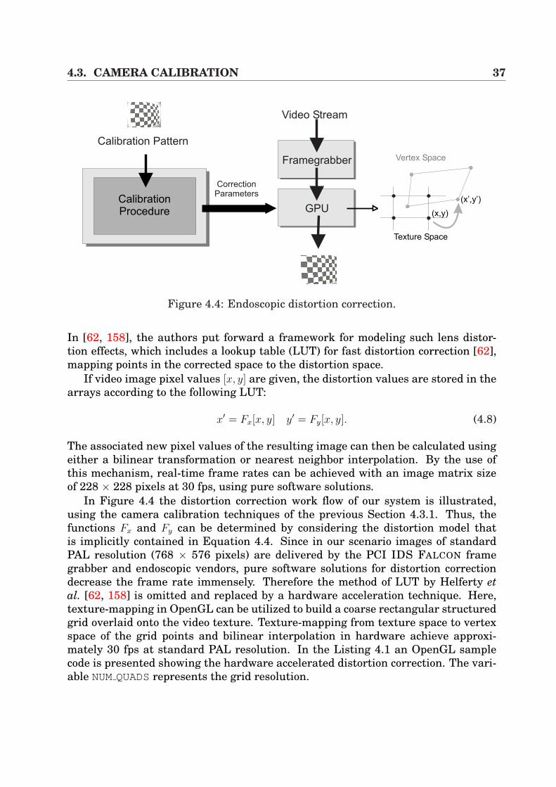
4.3. CAMERA CALIBRATION 37
Calibration Pattern
CalibrationProcedure
CorrectionParameters
Framegrabber
GPU
Video Stream
Texture Space
Vertex Space
(x’,y’)
(x,y)
Figure 4.4: Endoscopic distortion correction.
In [62, 158], the authors put forward a framework for modeling such lens distor-tion effects, which includes a lookup table (LUT) for fast distortion correction [62],mapping points in the corrected space to the distortion space.
If video image pixel values [x, y] are given, the distortion values are stored in thearrays according to the following LUT:
x′ = Fx[x, y] y′ = Fy[x, y]. (4.8)
The associated new pixel values of the resulting image can then be calculated usingeither a bilinear transformation or nearest neighbor interpolation. By the use ofthis mechanism, real-time frame rates can be achieved with an image matrix sizeof 228 × 228 pixels at 30 fps, using pure software solutions.
In Figure 4.4 the distortion correction work flow of our system is illustrated,using the camera calibration techniques of the previous Section 4.3.1. Thus, thefunctions Fx and Fy can be determined by considering the distortion model thatis implicitly contained in Equation 4.4. Since in our scenario images of standardPAL resolution (768 × 576 pixels) are delivered by the PCI IDS FALCON framegrabber and endoscopic vendors, pure software solutions for distortion correctiondecrease the frame rate immensely. Therefore the method of LUT by Helferty etal. [62, 158] is omitted and replaced by a hardware acceleration technique. Here,texture-mapping in OpenGL can be utilized to build a coarse rectangular structuredgrid overlaid onto the video texture. Texture-mapping from texture space to vertexspace of the grid points and bilinear interpolation in hardware achieve approxi-mately 30 fps at standard PAL resolution. In the Listing 4.1 an OpenGL samplecode is presented showing the hardware accelerated distortion correction. The vari-able NUMQUADSrepresents the grid resolution.
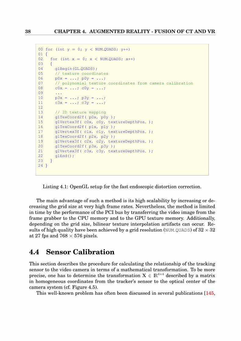
38 CHAPTER 4. AUGMENTED REALITY - FUSION OF CT AND VR
00 for (int y = 0; y < NUMQUADS; y++)01 02 for (int x = 0; x < NUMQUADS; x++)03 04 glBegin(GL QUADS);05 // texture coordinates06 p0x = ...; p0y = ...;07 // polynomial texture coordinates from camera calibration08 c0x = ...; c0y = ...;09 ...10 p3x = ...; p3y = ...;11 c3x = ...; c3y = ...;1213 // 2D texture mapping14 glTexCoord2f( p0x, p0y );15 glVertex3f( c0x, c0y, textureDepthPos );16 glTexCoord2f( p1x, p1y );17 glVertex3f( c1x, c1y, textureDepthPos );18 glTexCoord2f( p2x, p2y );19 glVertex3f( c2x, c2y, textureDepthPos );20 glTexCoord2f( p3x, p3y );21 glVertex3f( c3x, c3y, textureDepthPos );22 glEnd();23 24
Listing 4.1: OpenGL setup for the fast endoscopic distortion correction.
The main advantage of such a method is its high scalability by increasing or de-creasing the grid size at very high frame rates. Nevertheless, the method is limitedin time by the performance of the PCI bus by transferring the video image from theframe grabber to the CPU memory and to the GPU texture memory. Additionally,depending on the grid size, bilinear texture interpolation artifacts can occur. Re-sults of high quality have been achieved by a grid resolution (NUMQUADS) of 32 × 32at 27 fps and 768 × 576 pixels.
4.4 Sensor CalibrationThis section describes the procedure for calculating the relationship of the trackingsensor to the video camera in terms of a mathematical transformation. To be moreprecise, one has to determine the transformation X ∈ IR4×4 described by a matrixin homogeneous coordinates from the tracker’s sensor to the optical center of thecamera system (cf. Figure 4.5).
This well-known problem has often been discussed in several publications [145,
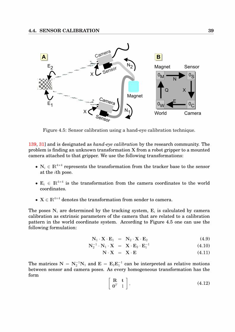
4.4. SENSOR CALIBRATION 39
Sensor
Camera
Sensor
Camera
Magnet
N2
X
X
E1
E2
N1
0W 0C
0M 0S
Q
N
X
E
AA AB
Magnet Sensor
World Camera
Figure 4.5: Sensor calibration using a hand-eye calibration technique.
139, 31] and is designated as hand-eye calibration by the research community. Theproblem is finding an unknown transformation X from a robot gripper to a mountedcamera attached to that gripper. We use the following transformations:
• Ni ∈ IR4×4 represents the transformation from the tracker base to the sensorat the ith pose.
• Ei ∈ IR4×4 is the transformation from the camera coordinates to the worldcoordinates.
• X ∈ IR4×4 denotes the transformation from sender to camera.
The poses Ni are determined by the tracking system, Ei is calculated by cameracalibration as extrinsic parameters of the camera that are related to a calibrationpattern in the world coordinate system. According to Figure 4.5 one can use thefollowing formulation:
N1 ·X · E1 = N2 ·X · E2 (4.9)N−1
2 ·N1 ·X = X · E2 · E−11 (4.10)
N ·X = X · E (4.11)
The matrices N = N−12 N1 and E = E2E
−11 can be interpreted as relative motions
between sensor and camera poses. As every homogeneous transformation has theform [
R t0T 1
], (4.12)
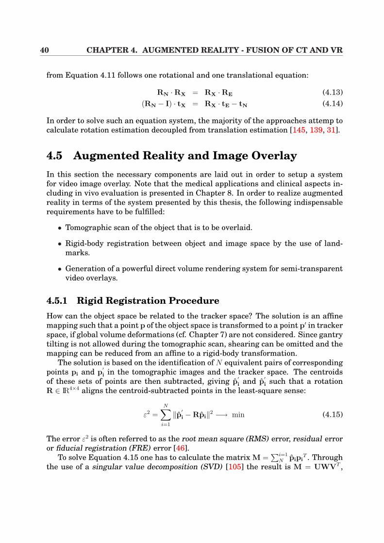
40 CHAPTER 4. AUGMENTED REALITY - FUSION OF CT AND VR
from Equation 4.11 follows one rotational and one translational equation:
RN ·RX = RX ·RE (4.13)(RN − I) · tX = RX · tE − tN (4.14)
In order to solve such an equation system, the majority of the approaches attemp tocalculate rotation estimation decoupled from translation estimation [145, 139, 31].
4.5 Augmented Reality and Image OverlayIn this section the necessary components are laid out in order to setup a systemfor video image overlay. Note that the medical applications and clinical aspects in-cluding in vivo evaluation is presented in Chapter 8. In order to realize augmentedreality in terms of the system presented by this thesis, the following indispensablerequirements have to be fulfilled:
• Tomographic scan of the object that is to be overlaid.
• Rigid-body registration between object and image space by the use of land-marks.
• Generation of a powerful direct volume rendering system for semi-transparentvideo overlays.
4.5.1 Rigid Registration ProcedureHow can the object space be related to the tracker space? The solution is an affinemapping such that a point p of the object space is transformed to a point p′ in trackerspace, if global volume deformations (cf. Chapter 7) are not considered. Since gantrytilting is not allowed during the tomographic scan, shearing can be omitted and themapping can be reduced from an affine to a rigid-body transformation.
The solution is based on the identification of N equivalent pairs of correspondingpoints pi and p
′i in the tomographic images and the tracker space. The centroids
of these sets of points are then subtracted, giving p′i and p
′i such that a rotation
R ∈ IR4×4 aligns the centroid-subtracted points in the least-square sense:
ε2 =N∑
i=1
‖p′i −Rpi‖2 −→ min (4.15)
The error ε2 is often referred to as the root mean square (RMS) error, residual erroror fiducial registration (FRE) error [46].
To solve Equation 4.15 one has to calculate the matrix M =∑i=1
N pipiT . Through
the use of a singular value decomposition (SVD) [105] the result is M = UWVT ,
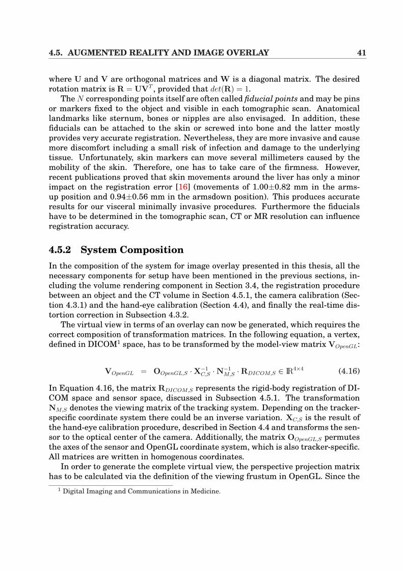
4.5. AUGMENTED REALITY AND IMAGE OVERLAY 41
where U and V are orthogonal matrices and W is a diagonal matrix. The desiredrotation matrix is R = UVT , provided that det(R) = 1.
The N corresponding points itself are often called fiducial points and may be pinsor markers fixed to the object and visible in each tomographic scan. Anatomicallandmarks like sternum, bones or nipples are also envisaged. In addition, thesefiducials can be attached to the skin or screwed into bone and the latter mostlyprovides very accurate registration. Nevertheless, they are more invasive and causemore discomfort including a small risk of infection and damage to the underlyingtissue. Unfortunately, skin markers can move several millimeters caused by themobility of the skin. Therefore, one has to take care of the firmness. However,recent publications proved that skin movements around the liver has only a minorimpact on the registration error [16] (movements of 1.00±0.82 mm in the arms-up position and 0.94±0.56 mm in the armsdown position). This produces accurateresults for our visceral minimally invasive procedures. Furthermore the fiducialshave to be determined in the tomographic scan, CT or MR resolution can influenceregistration accuracy.
4.5.2 System CompositionIn the composition of the system for image overlay presented in this thesis, all thenecessary components for setup have been mentioned in the previous sections, in-cluding the volume rendering component in Section 3.4, the registration procedurebetween an object and the CT volume in Section 4.5.1, the camera calibration (Sec-tion 4.3.1) and the hand-eye calibration (Section 4.4), and finally the real-time dis-tortion correction in Subsection 4.3.2.
The virtual view in terms of an overlay can now be generated, which requires thecorrect composition of transformation matrices. In the following equation, a vertex,defined in DICOM1 space, has to be transformed by the model-view matrix VOpenGL:
VOpenGL = OOpenGL,S ·X−1C,S ·N−1
M,S ·RDICOM,S ∈ IR4×4 (4.16)
In Equation 4.16, the matrix RDICOM,S represents the rigid-body registration of DI-COM space and sensor space, discussed in Subsection 4.5.1. The transformationNM,S denotes the viewing matrix of the tracking system. Depending on the tracker-specific coordinate system there could be an inverse variation. XC,S is the result ofthe hand-eye calibration procedure, described in Section 4.4 and transforms the sen-sor to the optical center of the camera. Additionally, the matrix OOpenGL,S permutesthe axes of the sensor and OpenGL coordinate system, which is also tracker-specific.All matrices are written in homogenous coordinates.
In order to generate the complete virtual view, the perspective projection matrixhas to be calculated via the definition of the viewing frustum in OpenGL. Since the
1 Digital Imaging and Communications in Medicine.
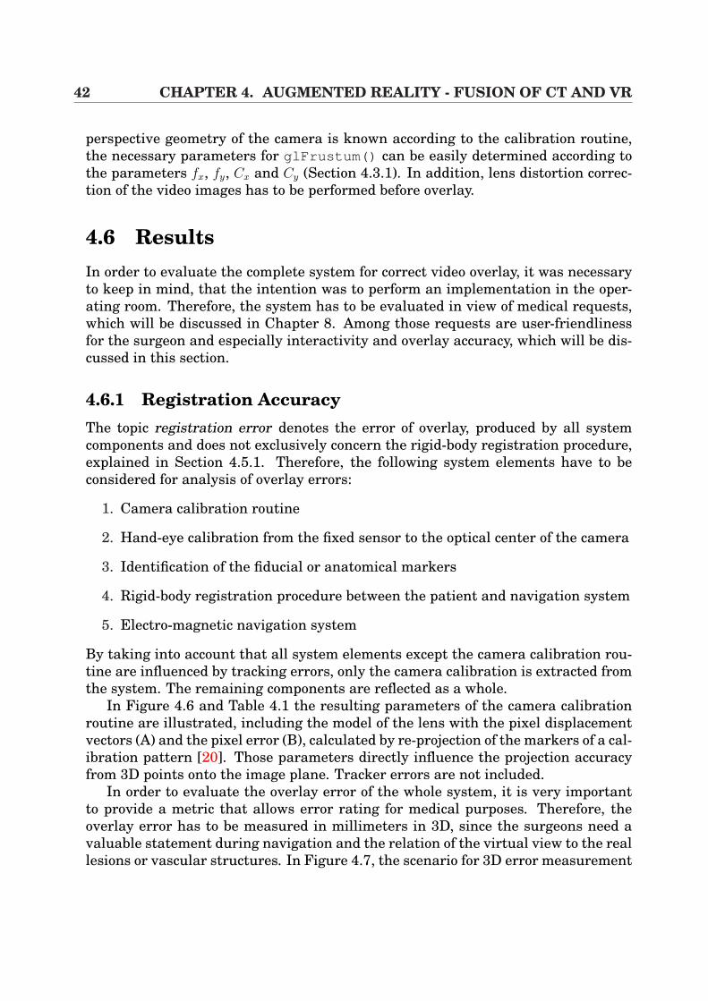
42 CHAPTER 4. AUGMENTED REALITY - FUSION OF CT AND VR
perspective geometry of the camera is known according to the calibration routine,the necessary parameters for glFrustum() can be easily determined according tothe parameters fx, fy, Cx and Cy (Section 4.3.1). In addition, lens distortion correc-tion of the video images has to be performed before overlay.
4.6 ResultsIn order to evaluate the complete system for correct video overlay, it was necessaryto keep in mind, that the intention was to perform an implementation in the oper-ating room. Therefore, the system has to be evaluated in view of medical requests,which will be discussed in Chapter 8. Among those requests are user-friendlinessfor the surgeon and especially interactivity and overlay accuracy, which will be dis-cussed in this section.
4.6.1 Registration AccuracyThe topic registration error denotes the error of overlay, produced by all systemcomponents and does not exclusively concern the rigid-body registration procedure,explained in Section 4.5.1. Therefore, the following system elements have to beconsidered for analysis of overlay errors:
1. Camera calibration routine
2. Hand-eye calibration from the fixed sensor to the optical center of the camera
3. Identification of the fiducial or anatomical markers
4. Rigid-body registration procedure between the patient and navigation system
5. Electro-magnetic navigation system
By taking into account that all system elements except the camera calibration rou-tine are influenced by tracking errors, only the camera calibration is extracted fromthe system. The remaining components are reflected as a whole.
In Figure 4.6 and Table 4.1 the resulting parameters of the camera calibrationroutine are illustrated, including the model of the lens with the pixel displacementvectors (A) and the pixel error (B), calculated by re-projection of the markers of a cal-ibration pattern [20]. Those parameters directly influence the projection accuracyfrom 3D points onto the image plane. Tracker errors are not included.
In order to evaluate the overlay error of the whole system, it is very importantto provide a metric that allows error rating for medical purposes. Therefore, theoverlay error has to be measured in millimeters in 3D, since the surgeons need avaluable statement during navigation and the relation of the virtual view to the reallesions or vascular structures. In Figure 4.7, the scenario for 3D error measurement
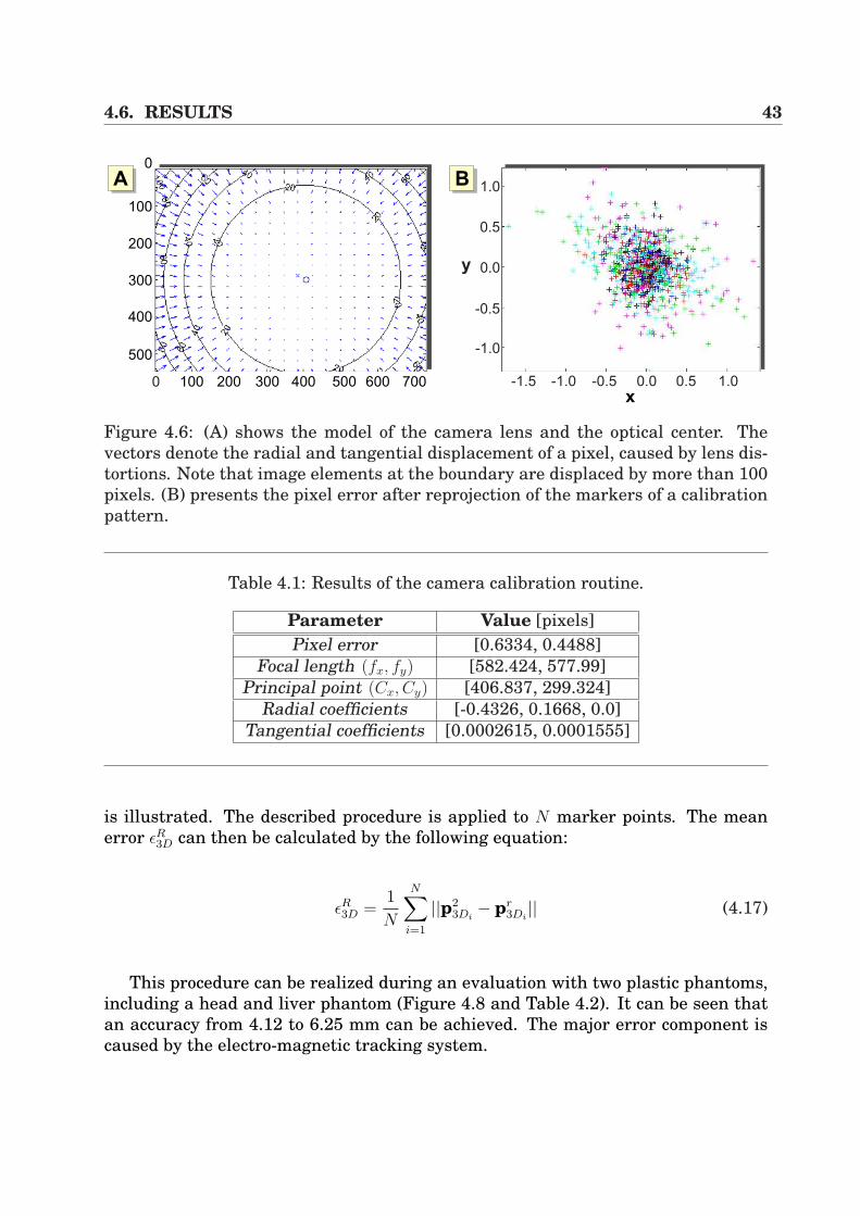
4.6. RESULTS 43
0 100 200 300 600500400 700
0
100
200
300
400
500
x-1.5 -1.0 -0.5 0.0 0.5 1.0
-1.0
-0.5
0.0
0.5
1.0
y
AA AB
Figure 4.6: (A) shows the model of the camera lens and the optical center. Thevectors denote the radial and tangential displacement of a pixel, caused by lens dis-tortions. Note that image elements at the boundary are displaced by more than 100pixels. (B) presents the pixel error after reprojection of the markers of a calibrationpattern.
Table 4.1: Results of the camera calibration routine.
Parameter Value [pixels]Pixel error [0.6334, 0.4488]
Focal length (fx, fy) [582.424, 577.99]Principal point (Cx, Cy) [406.837, 299.324]
Radial coefficients [-0.4326, 0.1668, 0.0]Tangential coefficients [0.0002615, 0.0001555]
is illustrated. The described procedure is applied to N marker points. The meanerror εR
3D can then be calculated by the following equation:
εR3D =
1
N
N∑i=1
||p23Di
− pr3Di|| (4.17)
This procedure can be realized during an evaluation with two plastic phantoms,including a head and liver phantom (Figure 4.8 and Table 4.2). It can be seen thatan accuracy from 4.12 to 6.25 mm can be achieved. The major error component iscaused by the electro-magnetic tracking system.
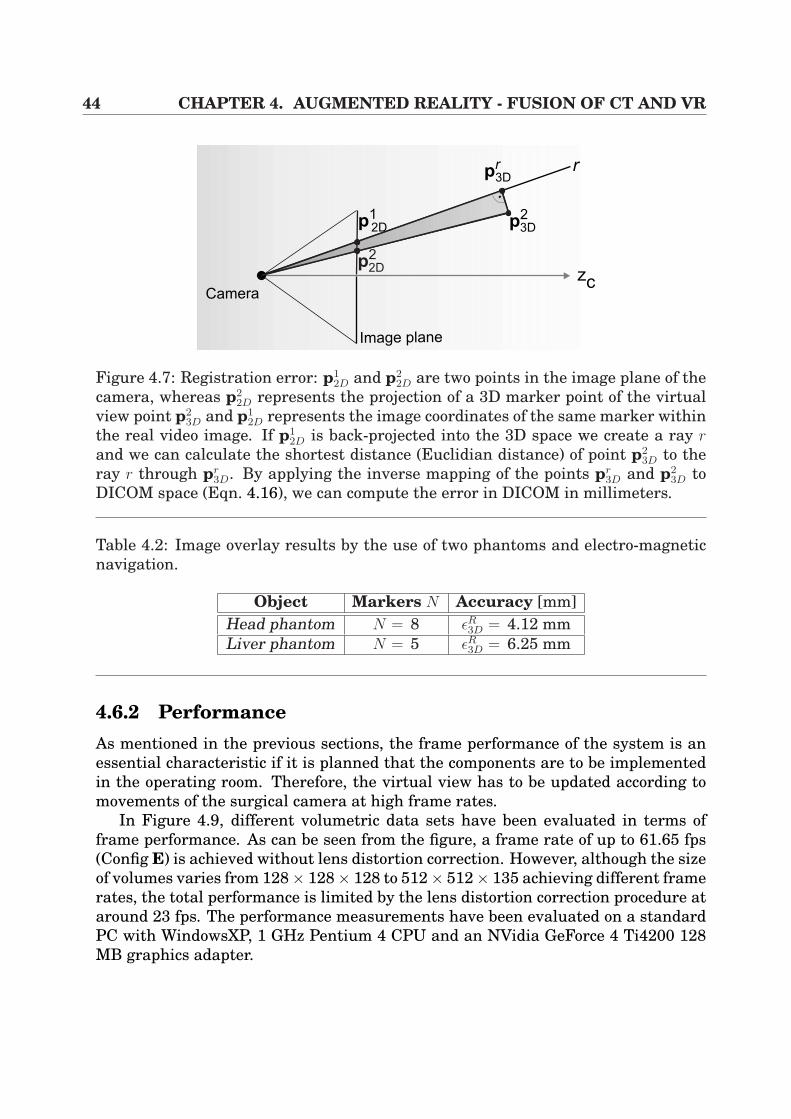
44 CHAPTER 4. AUGMENTED REALITY - FUSION OF CT AND VR
zc
Image plane
Camera
r
p12D p
23D
pr
3D
p22D
Figure 4.7: Registration error: p12D and p2
2D are two points in the image plane of thecamera, whereas p2
2D represents the projection of a 3D marker point of the virtualview point p2
3D and p12D represents the image coordinates of the same marker within
the real video image. If p12D is back-projected into the 3D space we create a ray r
and we can calculate the shortest distance (Euclidian distance) of point p23D to the
ray r through pr3D. By applying the inverse mapping of the points pr
3D and p23D to
DICOM space (Eqn. 4.16), we can compute the error in DICOM in millimeters.
Table 4.2: Image overlay results by the use of two phantoms and electro-magneticnavigation.
Object Markers N Accuracy [mm]Head phantom N = 8 εR
3D = 4.12 mmLiver phantom N = 5 εR
3D = 6.25 mm
4.6.2 PerformanceAs mentioned in the previous sections, the frame performance of the system is anessential characteristic if it is planned that the components are to be implementedin the operating room. Therefore, the virtual view has to be updated according tomovements of the surgical camera at high frame rates.
In Figure 4.9, different volumetric data sets have been evaluated in terms offrame performance. As can be seen from the figure, a frame rate of up to 61.65 fps(Config E) is achieved without lens distortion correction. However, although the sizeof volumes varies from 128× 128× 128 to 512× 512× 135 achieving different framerates, the total performance is limited by the lens distortion correction procedure ataround 23 fps. The performance measurements have been evaluated on a standardPC with WindowsXP, 1 GHz Pentium 4 CPU and an NVidia GeForce 4 Ti4200 128MB graphics adapter.
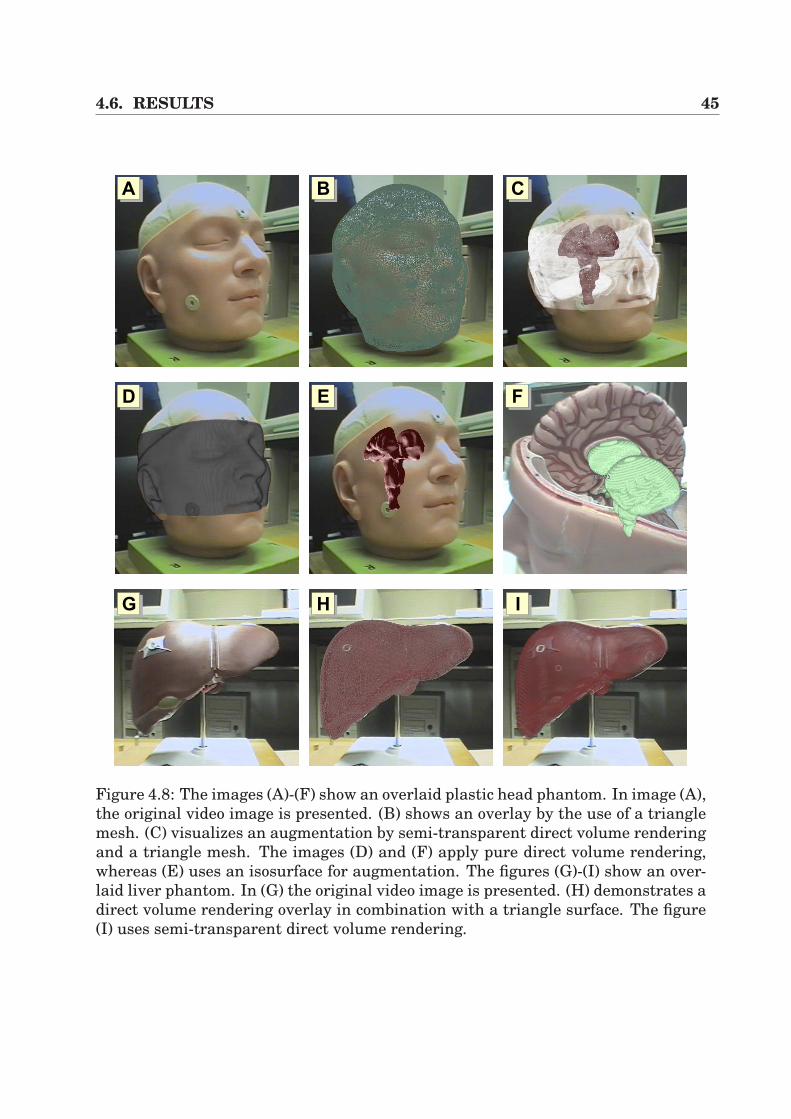
4.6. RESULTS 45
AA AB AC
AE F
AHAG AI
D
Figure 4.8: The images (A)-(F) show an overlaid plastic head phantom. In image (A),the original video image is presented. (B) shows an overlay by the use of a trianglemesh. (C) visualizes an augmentation by semi-transparent direct volume renderingand a triangle mesh. The images (D) and (F) apply pure direct volume rendering,whereas (E) uses an isosurface for augmentation. The figures (G)-(I) show an over-laid liver phantom. In (G) the original video image is presented. (H) demonstrates adirect volume rendering overlay in combination with a triangle surface. The figure(I) uses semi-transparent direct volume rendering.
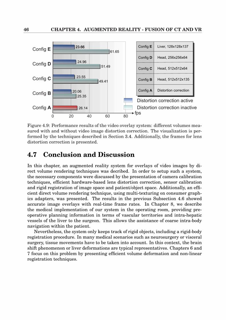
46 CHAPTER 4. AUGMENTED REALITY - FUSION OF CT AND VR
Config E
Config D
Config C
Config B
Config A
0 20 40 60 80fps
Config A
Config B
Config E
Config D
Config C
Liver, 128x128x137
Head, 256x256x64
Head, 512x512x64
Head, 512x512x135
Distortion correction
23.6623.66
61.65
24.96
51.49
23.55
49.41
20.06
25.35
26.14
Distortion correction active
Distortion correction inactive
Figure 4.9: Performance results of the video overlay system: different volumes mea-sured with and without video image distortion correction. The visualization is per-formed by the techniques described in Section 3.4. Additionally, the frames for lensdistortion correction is presented.
4.7 Conclusion and DiscussionIn this chapter, an augmented reality system for overlays of video images by di-rect volume rendering techniques was decribed. In order to setup such a system,the necessary components were discussed by the presentation of camera calibrationtechniques, efficient hardware-based lens distortion correction, sensor calibrationand rigid registration of image space and patient/object space. Additionally, an effi-cient direct volume rendering technique, using multi-texturing on consumer graph-ics adapters, was presented. The results in the previous Subsection 4.6 showedaccurate image overlays with real-time frame rates. In Chapter 8, we describethe medical implementation of our system in the operating room, providing pre-operative planning information in terms of vascular territories and intra-hepaticvessels of the liver to the surgeon. This allows the assistance of coarse intra-bodynavigation within the patient.
Nevertheless, the system only keeps track of rigid objects, including a rigid-bodyregistration procedure. In many medical scenarios such as neurosurgery or visceralsurgery, tissue movements have to be taken into account. In this context, the brainshift phenomenon or liver deformations are typical representatives. Chapters 6 and7 focus on this problem by presenting efficient volume deformation and non-linearregistration techniques.
Chapter 5
Augmented Virtuality -3D Scene Exploration
In the previous chapter, an Augmented Reality System was discussed in detail thatprovides guidance information to the user in real environments, according to Fig-ure 4.1. Contrary to such a framework, we now focus on the topic Augmented Vir-tuality which also allows the performance of the fusion of video sequences and 3Dvolumes.
The objective of Augmented Virtuality Systems (AVS) (Figure 4.1) is to enrichscenes or models in virtual environments by the use of real objects or information.In the context of this work, real medical video sequences are used in order to en-hance virtual objects that are based on CT/MR volumes and extracted isosurfaces.Thus, we want to realize a system which allows the virtual exploration of real 3Dscenes at high frame rates. Especially in the context of minimally invasive interven-tions, it is the long-term aim to post-operatively explore the inner organs within thepneumoperitoneum. The results achieved in this chapter provide the basic steps.
This chapter is divided into the following sections. In Section 5.1, the topic oftexture-mapped videos is introduced. Then, some previous work is presented inSection 5.2. In Section 5.3 the system’s concepts are described, including meshgeneration, calibration and registration steps. Since high frame performance is ofessential need for such a system, hardware acceleration has to be introduced. There-fore, the implementation of such an interactive system is extensively described inSection 5.4. In the following Section 5.5, the results of the algorithm are presented,whereas Section 5.6 discusses some possible medical application scenarios. Finally,the chapter is concluded in Section 5.7.
5.1 IntroductionIn Figure 5.1 a possible basic scenario is illustrated in which calibrated streams ofvideo images are taken from different camera poses (Cami, i = 1...N) of an object O.
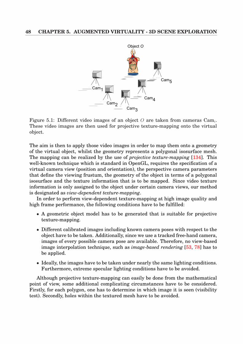
48 CHAPTER 5. AUGMENTED VIRTUALITY - 3D SCENE EXPLORATION
Cam5
Cam4
Cam3
Cam2
Cam1
Object O
Figure 5.1: Different video images of an object O are taken from cameras Cami.These video images are then used for projective texture-mapping onto the virtualobject.
The aim is then to apply those video images in order to map them onto a geometryof the virtual object, whilst the geometry represents a polygonal isosurface mesh.The mapping can be realized by the use of projective texture-mapping [134]. Thiswell-known technique which is standard in OpenGL, requires the specification of avirtual camera view (position and orientation), the perspective camera parametersthat define the viewing frustum, the geometry of the object in terms of a polygonalisosurface and the texture information that is to be mapped. Since video textureinformation is only assigned to the object under certain camera views, our methodis designated as view-dependent texture-mapping.
In order to perform view-dependent texture-mapping at high image quality andhigh frame performance, the following conditions have to be fulfilled:
• A geometric object model has to be generated that is suitable for projectivetexture-mapping.
• Different calibrated images including known camera poses with respect to theobject have to be taken. Additionally, since we use a tracked free-hand camera,images of every possible camera pose are available. Therefore, no view-basedimage interpolation technique, such as image-based rendering [53, 78] has tobe applied.
• Ideally, the images have to be taken under nearly the same lighting conditions.Furthermore, extreme specular lighting conditions have to be avoided.
Although projective texture-mapping can easily be done from the mathematicalpoint of view, some additional complicating circumstances have to be considered.Firstly, for each polygon, one has to determine in which image it is seen (visibilitytest). Secondly, holes within the textured mesh have to be avoided.
5.2. PREVIOUS WORK 49
Taking into account the mentioned conditions above, the exploration of a 3Dscene/object should then be possible with high image quality at high frame rates.
5.2 Previous WorkA similar work for object texturing has been published by Pulli et al. [106]. In theirapproach, called view-based rendering, camera images are utilized at free poses inorder to generate new views. This is done by separating the set of camera viewpoints into a Delaunay triangulation. After a barycentric interpolation of the threeview points, defined at the triangle vertices, each image is individually renderedfrom the discrete view and blended into a single result image by a specific weightingscheme. In addition, the authors perform a visibility test in which the texturingof occluded polygons is avoided by keeping track of the distance of the polygon tothe camera position. In order to achieve visually pleasant results, some furthertexturing conditions are introduced such that the angle between the polygon normaland the camera viewing direction is considered. Finally, hole filling is possible.
Of similarity to the above method is the approach presented by Debevec etal. [34]. By the application of so-called view maps for each of the polygons, which areboth generated in a preprocessing step, arbitrary new views can be interpolated bythe view map’s delivered discrete views and their corresponding blending weights.Additionally, hole filling is also possible in order to generate pleasant rendering re-sults.
Dey et al. [35] present a method that has been developed for minimally invasiveneurosurgical interventions. Real endoscopic video information is projected onto atriangle mesh that has been extracted from a CT head. The augmentation can thenbe presented to the surgeon via the endoscopic monitor. In addition, stereo ren-dering is possible. The extrinsic parameters of the camera are determined by theuse of an optical navigation system (Section 2.2). Furthermore, a rigid registrationbetween the camera space and the object/patient space is performed by utilizingfiducial markers, which is very similar to the approach (Subsection 4.5.1) herein.However, the drawback of this method is that the projected video information isonly temporarily available. Additionally, the triangle mesh is only partially tex-tured according to the endoscope’s restricted view. Thus, an interactive 3D sceneexploration of the whole object is not possible.
In addition, the techniques of image-based rendering [53, 78] are to be men-tioned, since they are strongly related to this topic. These methods produce result-ing scene images by the application of image sequences and a set of known cam-era viewpoints. An abstract description is given by the plenoptic function L(x, φ, θ)which calculates the radiance of a given point x ∈ R3 and a given direction [78].Since in reality only discrete camera poses are available, Gortler et al. [53] intro-duced the Lumigraph/Lightfield using a two-plane parametrization for the reduc-tion of the plenoptic function from 5D to 4D. However, since in the scenario in this
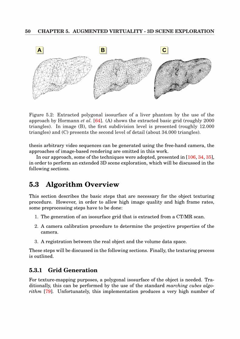
50 CHAPTER 5. AUGMENTED VIRTUALITY - 3D SCENE EXPLORATION
AA AB AC
Figure 5.2: Extracted polygonal isosurface of a liver phantom by the use of theapproach by Hormann et al. [64]. (A) shows the extracted basic grid (roughly 2000triangles). In image (B), the first subdivision level is presented (roughly 12.000triangles) and (C) presents the second level of detail (about 34.000 triangles).
thesis arbitrary video sequences can be generated using the free-hand camera, theapproaches of image-based rendering are omitted in this work.
In our approach, some of the techniques were adopted, presented in [106, 34, 35],in order to perform an extended 3D scene exploration, which will be discussed in thefollowing sections.
5.3 Algorithm OverviewThis section describes the basic steps that are necessary for the object texturingprocedure. However, in order to allow high image quality and high frame rates,some preprocessing steps have to be done:
1. The generation of an isosurface grid that is extracted from a CT/MR scan.
2. A camera calibration procedure to determine the projective properties of thecamera.
3. A registration between the real object and the volume data space.
These steps will be discussed in the following sections. Finally, the texturing processis outlined.
5.3.1 Grid GenerationFor texture-mapping purposes, a polygonal isosurface of the object is needed. Tra-ditionally, this can be performed by the use of the standard marching cubes algo-rithm [79]. Unfortunately, this implementation produces a very high number of
5.3. ALGORITHM OVERVIEW 51
triangles that have to be processed. Especially in the context of medical CT/MRscans, the set of produced triangles contains too many elements, depending on theslice artifacts of the volume. In addition, since we want to use triangle meshes fortexture-mapping, a balance must be found between the number of polygons and im-age quality. Later, in Section 5.4 it will be shown, that the number of triangles willbe restricted by the hardware’s capability in order to keep interactive rendering athigh image quality.
There are a variety of different further techniques for the production of polygo-nal meshes, ranging from commercial solutions like AMIRA [143] to special-purposedevelopments as presented by Hormann et al. [64]. Although AMIRA provides dif-ferent grid processing tools, the approach by Hormann et al. is more suitable forthese purposes. In this context, an algorithm for hierarchical grid extraction forisosurfaces is implemented, where a coarse base grid is generated from a volumeat coarse hierarchy. The resulting base grid can then be adaptively refined for ourpurposes at different levels of detail.
In Figure 5.2 an example of an artificial liver at different hierarchical levels isillustrated, including the base grid and two subdivision levels. In (A) approximately2000 triangles build the base grid. In the following subdivision level (B), the meshcontains about 12.000 triangles, whereas the final level mesh (C) consists of 34.000triangles.
5.3.2 CalibrationSince for the purpose of this work calibrated streams of video images of the realobject were desired, the camera system has to be calibrated in a preprocessing step.Therefore, the following steps have to be performed:
1. Calibration of the projective camera properties (intrinsic parameters).
2. Determination of the camera’s pose (extrinsic parameters).
Fortunately, the results of Section 4.3 can be utilized, where the basics of cameracalibration were introduced. Additionally, an electro-magnetic navigation systemis used, the sensor of which is attached to the camera to get the extrinsic cameraparameters. Furthermore, the transformation from the sensor to the optical centerof the camera has to be determined. Hereby, the results of Section 4.4 are used.
5.3.3 RegistrationAs in the previous chapter, pre-calculated results of the rigid registration techniqueintroduced in Subsection 4.5.1 can be used. In this context, fiducial or anatomicalmarkers that are attached to the object have to be identified, both on the object andwithin the CT/MR volume.
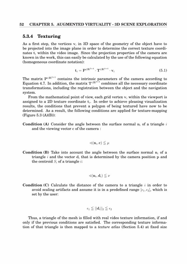
52 CHAPTER 5. AUGMENTED VIRTUALITY - 3D SCENE EXPLORATION
5.3.4 TexturingAs a first step, the vertices vi in 3D space of the geometry of the object have tobe projected into the image plane in order to determine the correct texture coordi-nates ti within the video image. Since the projection properties of the camera areknown in the work, this can easily be calculated by the use of the following equation(homogeneous coordinate notation):
ti = P∈IR3×4 ·T∈IR4×4 · vi (5.1)
The matrix P∈IR3×4 contains the intrinsic parameters of the camera according toEquation 4.7. In addition, the matrix T∈IR4×4 combines all the necessary coordinatetransformations, including the registration between the object and the navigationsystem.
From the mathematical point of view, each grid vertex vi within the viewport isassigned to a 2D texture coordinate ti. In order to achieve pleasing visualizationresults, the conditions that prevent a polygon of being textured have now to bedetermined. As a result, the following conditions are applied for texture-mapping(Figure 5.3 (A)(B)):
Condition (A) Consider the angle between the surface normal ni of a triangle iand the viewing vector c of the camera :
^(ni, c) 5 µ
Condition (B) Take into account the angle between the surface normal ni of atriangle i and the vector di that is determined by the camera position p andthe centroid Si of a triangle i:
^(ni,di) 5 ν
Condition (C) Calculate the distance of the camera to a triangle i in order toavoid scaling artifacts and assume it is in a predefined range [ε1, ε2], which isset by the user:
ε1 5 ||di||2 5 ε2
Thus, a triangle of the mesh is filled with real video texture information, if andonly if the previous conditions are satisfied. The corresponding texture informa-tion of that triangle is then mapped to a texture atlas (Section 5.4) at fixed size
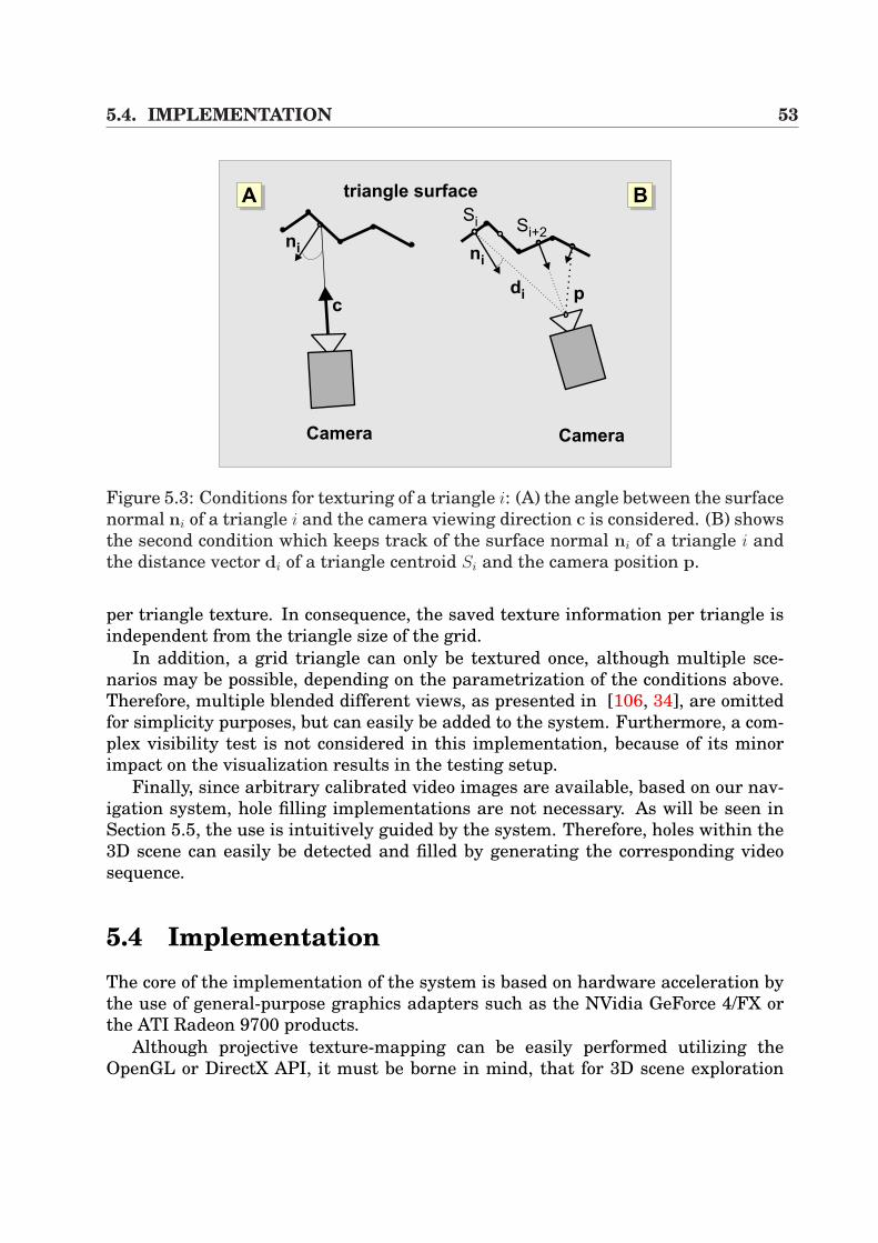
5.4. IMPLEMENTATION 53
AA AB
Si+2
c
Camera
Si
ni
p
Camera
ni
di
triangle surface
Figure 5.3: Conditions for texturing of a triangle i: (A) the angle between the surfacenormal ni of a triangle i and the camera viewing direction c is considered. (B) showsthe second condition which keeps track of the surface normal ni of a triangle i andthe distance vector di of a triangle centroid Si and the camera position p.
per triangle texture. In consequence, the saved texture information per triangle isindependent from the triangle size of the grid.
In addition, a grid triangle can only be textured once, although multiple sce-narios may be possible, depending on the parametrization of the conditions above.Therefore, multiple blended different views, as presented in [106, 34], are omittedfor simplicity purposes, but can easily be added to the system. Furthermore, a com-plex visibility test is not considered in this implementation, because of its minorimpact on the visualization results in the testing setup.
Finally, since arbitrary calibrated video images are available, based on our nav-igation system, hole filling implementations are not necessary. As will be seen inSection 5.5, the use is intuitively guided by the system. Therefore, holes within the3D scene can easily be detected and filled by generating the corresponding videosequence.
5.4 ImplementationThe core of the implementation of the system is based on hardware acceleration bythe use of general-purpose graphics adapters such as the NVidia GeForce 4/FX orthe ATI Radeon 9700 products.
Although projective texture-mapping can be easily performed utilizing theOpenGL or DirectX API, it must be borne in mind, that for 3D scene exploration
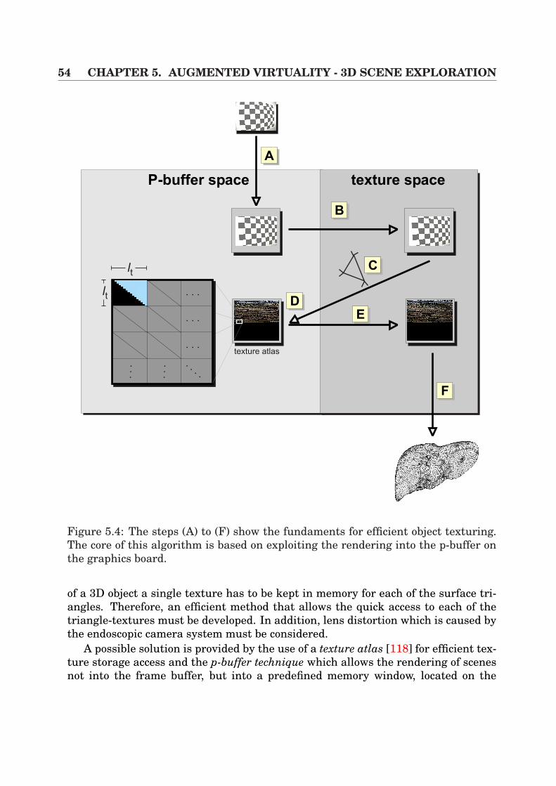
54 CHAPTER 5. AUGMENTED VIRTUALITY - 3D SCENE EXPLORATION
AA
texture atlas
lt
lt
AC
ADAE
AF
P-buffer space texture space
AB
Figure 5.4: The steps (A) to (F) show the fundaments for efficient object texturing.The core of this algorithm is based on exploiting the rendering into the p-buffer onthe graphics board.
of a 3D object a single texture has to be kept in memory for each of the surface tri-angles. Therefore, an efficient method that allows the quick access to each of thetriangle-textures must be developed. In addition, lens distortion which is caused bythe endoscopic camera system must be considered.
A possible solution is provided by the use of a texture atlas [118] for efficient tex-ture storage access and the p-buffer technique which allows the rendering of scenesnot into the frame buffer, but into a predefined memory window, located on the
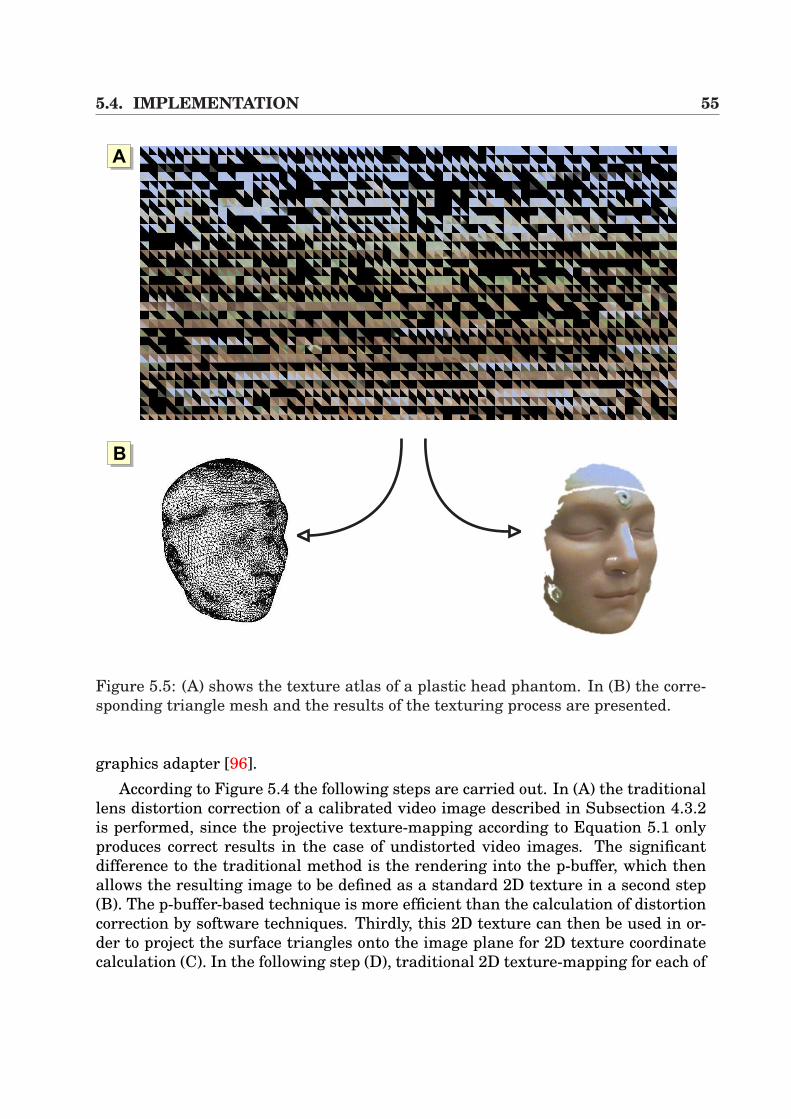
5.4. IMPLEMENTATION 55
AA
AB
Figure 5.5: (A) shows the texture atlas of a plastic head phantom. In (B) the corre-sponding triangle mesh and the results of the texturing process are presented.
graphics adapter [96].According to Figure 5.4 the following steps are carried out. In (A) the traditional
lens distortion correction of a calibrated video image described in Subsection 4.3.2is performed, since the projective texture-mapping according to Equation 5.1 onlyproduces correct results in the case of undistorted video images. The significantdifference to the traditional method is the rendering into the p-buffer, which thenallows the resulting image to be defined as a standard 2D texture in a second step(B). The p-buffer-based technique is more efficient than the calculation of distortioncorrection by software techniques. Thirdly, this 2D texture can then be used in or-der to project the surface triangles onto the image plane for 2D texture coordinatecalculation (C). In the following step (D), traditional 2D texture-mapping for each of
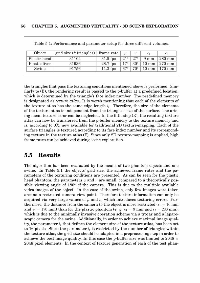
56 CHAPTER 5. AUGMENTED VIRTUALITY - 3D SCENE EXPLORATION
Table 5.1: Performance and parameter setup for three different volumes.
Object grid size (# triangles) frame rate µ ν ε1 ε2
Plastic head 31104 31.5 fps 21o 27o 9 mm 280 mmPlastic liver 31936 28.7 fps 17o 30o 10 mm 270 mm
Swine 91756 11.3 fps 67o 70o 10 mm 170 mm
the triangles that pass the texturing conditions mentioned above is performed. Sim-ilarly to (B), the rendering result is passed to the p-buffer at a predefined location,which is determined by the triangle’s face index number. The predefined memoryis designated as texture atlas. It is worth mentioning that each of the elements ofthe texture atlas has the same edge length lt. Therefore, the size of the elementsof the texture atlas is independent from the triangles’ size of the surface. The aris-ing mean texture error can be neglected. In the fifth step (E), the resulting textureatlas can now be transferred from the p-buffer memory to the texture memory andis, according to (C), now available for traditional 2D texture-mapping. Each of thesurface triangles is textured according to its face index number and its correspond-ing texture in the texture atlas (F). Since only 2D texture-mapping is applied, highframe rates can be achieved during scene exploration.
5.5 ResultsThe algorithm has been evaluated by the means of two phantom objects and oneswine. In Table 5.1 the objects’ grid size, the achieved frame rates and the pa-rameters of the texturing conditions are presented. As can be seen for the plastichead phantom, the parameters µ and ν are small, compared to a theoretically pos-sible viewing angle of 180o of the camera. This is due to the multiple availablevideo images of the object. In the case of the swine, only few images were takenaround a restricted camera view point. Therefore texture information can only beacquired via very large values of µ and ν, which introduces texturing errors. Fur-thermore, the distance from the camera to the object is more restricted (ε1 = 10 mmand ε2 = 170 mm) than for the plastic phantom (e. g. ε1 = 9 mm and ε2 = 280 mm),which is due to the minimally invasive operation scheme via a trocar and a laparo-scopic camera for the swine. Additionally, in order to achieve maximal image qual-ity, the parameter lt that defines the element size of the texture atlas, has been setto 16 pixels. Since the parameter lt is restricted by the number of triangles withinthe texture atlas, the grid size should be adapted in a preprocessing step in order toachieve the best image quality. In this case the p-buffer size was limited to 2048 ×2048 pixel elements. In the context of texture generation of each of the test phan-
5.6. APPLICATION 57
toms, the complete texturing process in combination with a hand-held camera takesonly one to three minutes in order to be ready for object exploration. An example ofa texture atlas is presented in Figure 5.5 (A). The black texture elements representtriangles that did not pass the texturing conditions. In (B) a triangle surface of aplastic head phantom and its texturing result is presented.
As far as the registration accuracy is concerned, the error is identical to the re-sults in Subsection 4.6.1, since the same rigid-body registration strategy has beenperformed. Additionally, the same camera-tracking setup has been utilized in termsof an endoscopic camera in combination with an electro-magnetic tracker. Further-more, the remaining hardware consists of a Pentium 1GHz CPU and a GeForce 4Ti4200 128MB graphics board, running under WindowsXP.
In Figure 5.6, the examples of the texturing algorithms are presented. The im-ages (A) and (B) visualize the 3D virtual plastic head phantom, including the resultsof two texturing processes. The pictures to the right show the triangles of the objectthat passed the texturing conditions. Analogous to the head phantom, the images(C) and (D) present the results of a liver plastic phantom.
5.6 ApplicationAccording to the previous section that showed different example objects, it becomesevident that the implemented algorithm provides a flexible tool for 3D object tex-turing at interactive frame rates. Therefore, there is a wide variety of possible ap-plications, ranging from commercial product presentations to medical applications.In the opinion of the writer, the vast majority of implementations can be seen in themedical field, as will be discussed in the next section.
5.6.1 Post-operative ExplorationAs has been seen in Section 2.1 which introduced the concepts and work flow ofminimally invasive surgery, these intervention schemes demand a lot of practice bythe surgeon as far as the orientation within the patient’s body is concerned. Bythe introduction of this algorithm it is now possible to post-operatively exploringparts of the intra-operative scene. Since the tracking information of the surgicaltools and streams of calibrated video images can easily be recorded, intra-operativeimages can be mapped onto the pre-operative patient geometry. In addition, in-strument paths can be visualized within the 3D model if tool tracking informationwas available during intervention. Therefore, a post-operative scene explorationcan be performed which could be used for teaching purposes. In Figure 5.7 (A) theperitoneum of the pre-operative CT volume of a swine has been removed by simplethreshold-based image segmentation. Afterwards, after triangle surface generationby AMIRA [143] (B), our algorithm has been applied in order to map the intra-operative scene onto the isosurface (C)(D). As a result of this, parts of the swine’s
58 CHAPTER 5. AUGMENTED VIRTUALITY - 3D SCENE EXPLORATION
liver and gallbladder are visible.As far as the image quality is concerned, the following circumstances must be
considered:
1. Texture distortions at the grid bounds
2. Soft-tissue deformation
The texture distortion at the grid bounds are caused by the fact that the laparo-scopic camera is inserted into the body via one trocar position. Therefore, in orderto make many triangles pass the texturing conditions, the angles µ and ν have to beset at a wide angle. Additional texturing errors are caused by soft-tissue deforma-tions of the liver. Since intra-operative video images are mapped onto pre-operativeCT information, tissue movements are not considered, caused by breathing or pa-tient positioning. In order to compensate such movements, non-linear registrationtechniques have to be introduced. In Chapters 6 and 7 some possible techniquesare introduced that could be used for compensation. However, in visceral surgerythere are not the same requirements in terms of accuracy, compared to neurosurgi-cal interventions. Therefore, for orientational purposes and coarse navigation, theachieved accuracy is sufficient [126].
5.6.2 Augmentation by Direct Volume RenderingIn order to enrich the presented 3D scene exploration, direct volume rendering tech-niques can be introduced. Thus, a fusion of intra-operative video sequences anddirect volume rendering can be performed, as presented in Section 3.4. Since theregistration between the video sequences and the CT volume is known according toSubsection 5.3.3, the visualization can be easily performed by correctly placing thevolume rendering result into the scene. Figure 5.8 illustrates some example imagesof a swine’s torso. (A) shows pure direct volume rendering, whereas (B) visualizessemi-transparently the texture-mapped intra-operative video images. Finally, im-age (C) displays the texture-mapped video images and the swine’s spine.
5.7 Conclusion and DiscussionThis chapter presented an efficient and flexible method for mapping real calibratedvideo streams onto the polygonal isosurface of an object. By the use of hardwareacceleration, fast object texture acquisition and interactive exploration is possible.In addition, first steps for mapping intra-operative video sequences within a swinesurgery have been described. In combination with direct volume rendering, thevirtual 3D scene can be enriched which can be used for post-operative inspectionand teaching purposes.
5.7. CONCLUSION AND DISCUSSION 59
Although the presented algorithm is a powerful tool, there are some drawbacksthat have to be discussed herein. Firstly, the algorithm works well in the case ofdiffuse surface lighting conditions. If specular illumination effects appear, suchas highlights, visual artifacts hamper the texture quality and thus the final ob-ject exploration. In order to handle such phenomena, additional texture blendingas presented by Pulli et al. [106] has to be introduced. Furthermore algorithms forhighlight reduction as provided by Vogt et al. [149] must be utilized.
Secondly, in the case of complex surface geometry, visibility tests have to be per-formed in order to avoid the texturing of covered triangles which negatively influ-ence the exploration quality. This is also valid for hole filling.
Finally, the biggest impact on the image quality is caused by soft-tissue deforma-tion of the inner organs in the context of medical applications. Since video imagesare mapped onto pre-operative CT information, the organ’s displacement has to beapproximated. In Chapters 6 and 7 this topic will be discussed again.
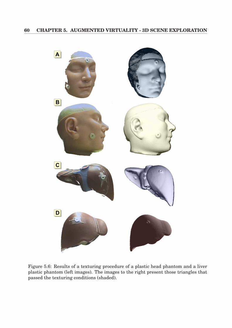
60 CHAPTER 5. AUGMENTED VIRTUALITY - 3D SCENE EXPLORATION
AA
AB
AC
AD
Figure 5.6: Results of a texturing procedure of a plastic head phantom and a liverplastic phantom (left images). The images to the right present those triangles thatpassed the texturing conditions (shaded).
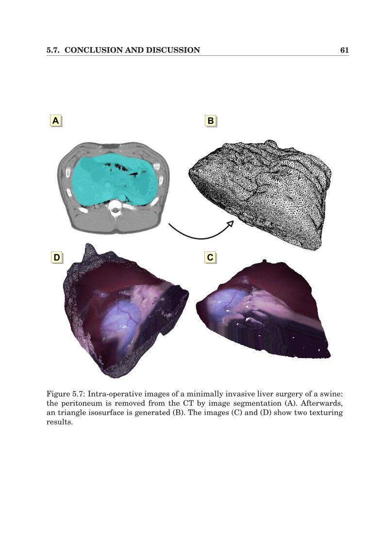
5.7. CONCLUSION AND DISCUSSION 61
AB
ACAD
AA
Figure 5.7: Intra-operative images of a minimally invasive liver surgery of a swine:the peritoneum is removed from the CT by image segmentation (A). Afterwards,an triangle isosurface is generated (B). The images (C) and (D) show two texturingresults.
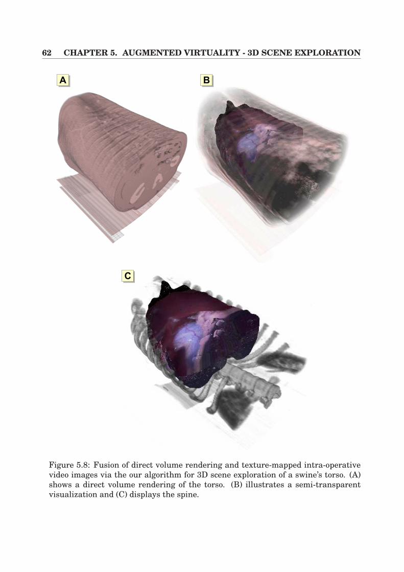
62 CHAPTER 5. AUGMENTED VIRTUALITY - 3D SCENE EXPLORATION
AA
AC
AB
Figure 5.8: Fusion of direct volume rendering and texture-mapped intra-operativevideo images via the our algorithm for 3D scene exploration of a swine’s torso. (A)shows a direct volume rendering of the torso. (B) illustrates a semi-transparentvisualization and (C) displays the spine.
Chapter 6
Interactive Volume Deformation
In the previous chapters, the focus was only on rigid tomographic volumes, whichwere used for rigid registration purposes in image overlay applications (Chapter 4)or real-time texturing (Chapter 5). However, in recent years some research groupshave emphasized the work on volume deformation, since there is a growing demandfor such applications. In particular, driven by the immense evolution of generalpurpose graphics adapters in the past two years, such solutions now have access tomany application fields. Additionally, relatively cheap product releases, based onrecent graphics adapters like the NVidia GeForce 4/FX or the Radeon 9700 128MBfrom ATI, provide a powerful approach with increasing flexibility in programmabil-ity and growing texture memory. In conjunction with standard APIs like OpenGLor DirectX, comfortable access to exploit the capabilities of the hardware is providedfor developers. This topic has been discussed in Section 3.2 by the explanation ofthe rendering pipeline.
The increasing need for volume deformation mostly is based on medical applica-tions. Using a pre-operative tomographic data volume, pre-planning steps can befulfilled by the surgeon in order to familiarize himself with the patient-individualanatomy and lesions. However, all preparations have to be updated during the in-tervention if soft-tissue deformation comes into play. Therefore, there is a need tointroduce efficient deformation mechanisms which allow a change of the shape of a3D volume, which can then be used for fast registration purposes for intra-operativeupdate. This will be discussed in the following Chapter 7.
In this chapter, the focus will be on approaches which deform medical scalar3D volumes that are represented on uniform grids. Furthermore, the focus willbe on general-purpose hardware-based techniques that allow an interactive render-ing. This chapter is divided into the following topics. In Section 6.1, previous workon volume deformation techniques is described. Following this, Section 6.2 detailsan algorithm which is based on hexahedra deformation in combination with axis-aligned slices. In the following Section 6.3 a new approach that is based on pixelshading techniques is introduced, including 3D dependent texture reads for acceler-ated visualization. This chapter is then concluded in Section 6.4.
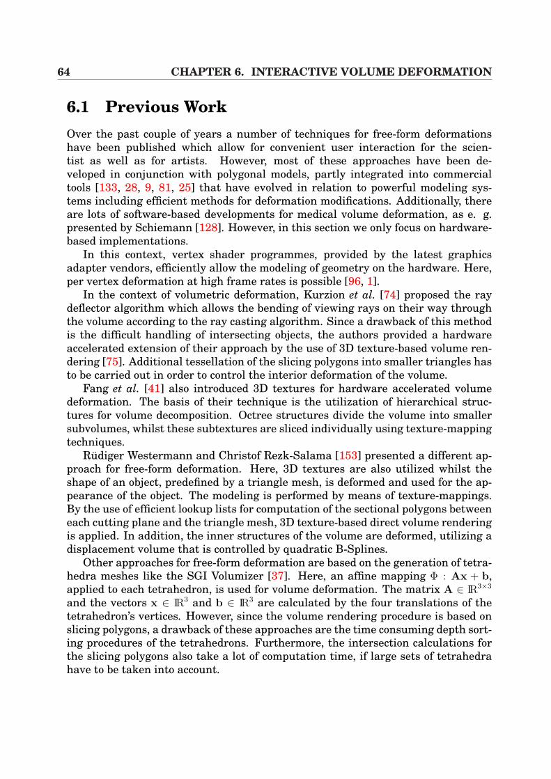
64 CHAPTER 6. INTERACTIVE VOLUME DEFORMATION
6.1 Previous WorkOver the past couple of years a number of techniques for free-form deformationshave been published which allow for convenient user interaction for the scien-tist as well as for artists. However, most of these approaches have been de-veloped in conjunction with polygonal models, partly integrated into commercialtools [133, 28, 9, 81, 25] that have evolved in relation to powerful modeling sys-tems including efficient methods for deformation modifications. Additionally, thereare lots of software-based developments for medical volume deformation, as e. g.presented by Schiemann [128]. However, in this section we only focus on hardware-based implementations.
In this context, vertex shader programmes, provided by the latest graphicsadapter vendors, efficiently allow the modeling of geometry on the hardware. Here,per vertex deformation at high frame rates is possible [96, 1].
In the context of volumetric deformation, Kurzion et al. [74] proposed the raydeflector algorithm which allows the bending of viewing rays on their way throughthe volume according to the ray casting algorithm. Since a drawback of this methodis the difficult handling of intersecting objects, the authors provided a hardwareaccelerated extension of their approach by the use of 3D texture-based volume ren-dering [75]. Additional tessellation of the slicing polygons into smaller triangles hasto be carried out in order to control the interior deformation of the volume.
Fang et al. [41] also introduced 3D textures for hardware accelerated volumedeformation. The basis of their technique is the utilization of hierarchical struc-tures for volume decomposition. Octree structures divide the volume into smallersubvolumes, whilst these subtextures are sliced individually using texture-mappingtechniques.
Rudiger Westermann and Christof Rezk-Salama [153] presented a different ap-proach for free-form deformation. Here, 3D textures are also utilized whilst theshape of an object, predefined by a triangle mesh, is deformed and used for the ap-pearance of the object. The modeling is performed by means of texture-mappings.By the use of efficient lookup lists for computation of the sectional polygons betweeneach cutting plane and the triangle mesh, 3D texture-based direct volume renderingis applied. In addition, the inner structures of the volume are deformed, utilizing adisplacement volume that is controlled by quadratic B-Splines.
Other approaches for free-form deformation are based on the generation of tetra-hedra meshes like the SGI Volumizer [37]. Here, an affine mapping Φ : Ax + b,applied to each tetrahedron, is used for volume deformation. The matrix A ∈ IR3×3
and the vectors x ∈ IR3 and b ∈ IR3 are calculated by the four translations of thetetrahedron’s vertices. However, since the volume rendering procedure is based onslicing polygons, a drawback of these approaches are the time consuming depth sort-ing procedures of the tetrahedrons. Furthermore, the intersection calculations forthe slicing polygons also take a lot of computation time, if large sets of tetrahedrahave to be taken into account.
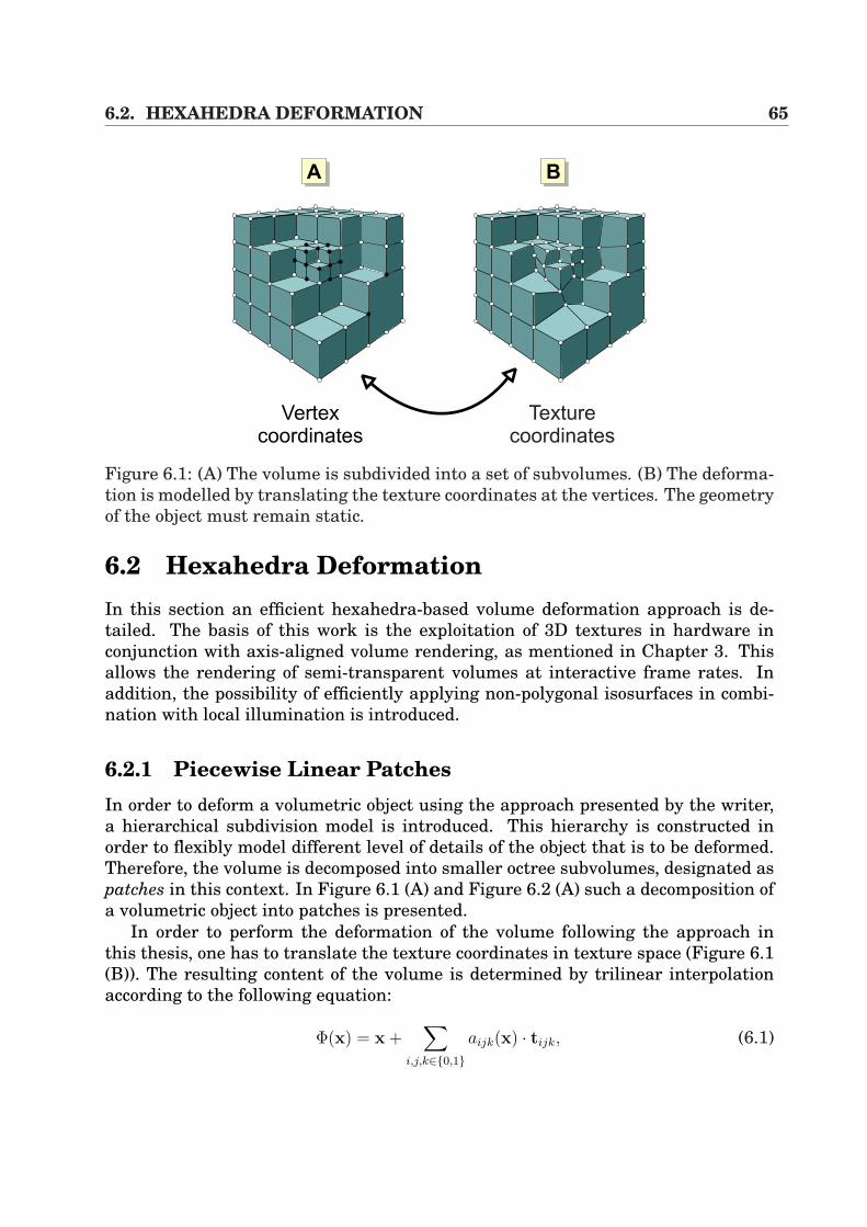
6.2. HEXAHEDRA DEFORMATION 65
Texture
coordinates
AA AB
Vertex
coordinates
Figure 6.1: (A) The volume is subdivided into a set of subvolumes. (B) The deforma-tion is modelled by translating the texture coordinates at the vertices. The geometryof the object must remain static.
6.2 Hexahedra DeformationIn this section an efficient hexahedra-based volume deformation approach is de-tailed. The basis of this work is the exploitation of 3D textures in hardware inconjunction with axis-aligned volume rendering, as mentioned in Chapter 3. Thisallows the rendering of semi-transparent volumes at interactive frame rates. Inaddition, the possibility of efficiently applying non-polygonal isosurfaces in combi-nation with local illumination is introduced.
6.2.1 Piecewise Linear PatchesIn order to deform a volumetric object using the approach presented by the writer,a hierarchical subdivision model is introduced. This hierarchy is constructed inorder to flexibly model different level of details of the object that is to be deformed.Therefore, the volume is decomposed into smaller octree subvolumes, designated aspatches in this context. In Figure 6.1 (A) and Figure 6.2 (A) such a decomposition ofa volumetric object into patches is presented.
In order to perform the deformation of the volume following the approach inthis thesis, one has to translate the texture coordinates in texture space (Figure 6.1(B)). The resulting content of the volume is determined by trilinear interpolationaccording to the following equation:
Φ(x) = x +∑
i,j,k∈0,1aijk(x) · tijk, (6.1)
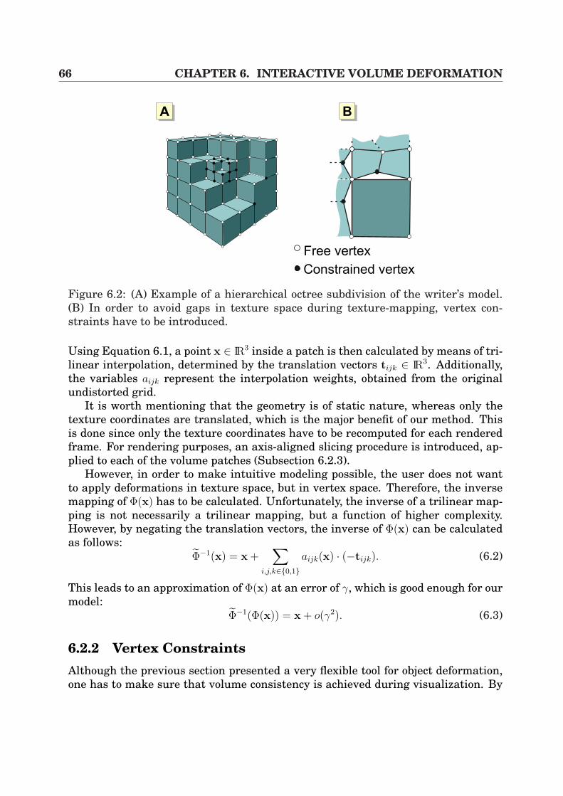
66 CHAPTER 6. INTERACTIVE VOLUME DEFORMATION
Free vertex
Constrained vertex
AA AB
Figure 6.2: (A) Example of a hierarchical octree subdivision of the writer’s model.(B) In order to avoid gaps in texture space during texture-mapping, vertex con-straints have to be introduced.
Using Equation 6.1, a point x ∈ IR3 inside a patch is then calculated by means of tri-linear interpolation, determined by the translation vectors tijk ∈ IR3. Additionally,the variables aijk represent the interpolation weights, obtained from the originalundistorted grid.
It is worth mentioning that the geometry is of static nature, whereas only thetexture coordinates are translated, which is the major benefit of our method. Thisis done since only the texture coordinates have to be recomputed for each renderedframe. For rendering purposes, an axis-aligned slicing procedure is introduced, ap-plied to each of the volume patches (Subsection 6.2.3).
However, in order to make intuitive modeling possible, the user does not wantto apply deformations in texture space, but in vertex space. Therefore, the inversemapping of Φ(x) has to be calculated. Unfortunately, the inverse of a trilinear map-ping is not necessarily a trilinear mapping, but a function of higher complexity.However, by negating the translation vectors, the inverse of Φ(x) can be calculatedas follows:
Φ−1(x) = x +∑
i,j,k∈0,1aijk(x) · (−tijk). (6.2)
This leads to an approximation of Φ(x) at an error of γ, which is good enough for ourmodel:
Φ−1(Φ(x)) = x + o(γ2). (6.3)
6.2.2 Vertex ConstraintsAlthough the previous section presented a very flexible tool for object deformation,one has to make sure that volume consistency is achieved during visualization. By
6.2. HEXAHEDRA DEFORMATION 67
V0
VC
V1
V3
V2
V1
V0
VC
AA AB
Figure 6.3: Vertex constraints: (A) shows the edge constraints. (B) visualizes theconstraints for faces.
the use of a hierarchical subvolume structure, additional constraints for vertex mod-eling have to be introduced to avoid errors. In addition, since the number of free ver-tices increases with the level of subdivision, a vertex reduction of possibly translatedvertices has to be performed in order to ease modeling for the user. As visualized inFigure 6.2 (B), certain inconsistencies will occur while subdividing the volume intosmaller patches. Without keeping track of constraints for the model vertices, gapsin texture space can arise during the texture-mapping procedure. We introduce thefollowing constraints into our model in order to handle inconsistency:
(1) CONSTRAINTS ON EDGES: Edges that share patches of different subdivisionlevels, have to remain collinear according to the following equation:
vc = (1− α)v0 + α · v1 (6.4)
Figure 6.3 (A) demonstrates this scenario. The inner vertex vc that has beenintroduced by patches of a higher subdivision level, has to be linearly interpo-lated by the neighboring vertices v0 and v1.
(2) CONSTRAINTS ON FACES: In a similar fashion to edge constraints, one hasto introduce constraints on faces. Here, faces that are elements of differentsubdivision levels must mould a coplanar polygon:
vc =3∑
i=0
aivi with3∑
i=0
ai = 1 (6.5)
In Figure 6.3 (B), the inner vertex vc is positioned by the surrounding verticesv0 · · ·v3.
Finally, in order to reduce computational expense for recursive constraints, we in-troduce the role, that patches can only be subdivided, if all neighbors have at leastthe same subdivision level.
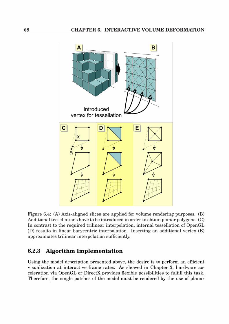
68 CHAPTER 6. INTERACTIVE VOLUME DEFORMATION
AA AB
Introducedvertex for tessellation
xi
yi
AC AD AE
Figure 6.4: (A) Axis-aligned slices are applied for volume rendering purposes. (B)Additional tessellations have to be introduced in order to obtain planar polygons. (C)In contrast to the required trilinear interpolation, internal tessellation of OpenGL(D) results in linear barycentric interpolation. Inserting an additional vertex (E)approximates trilinear interpolation sufficiently.
6.2.3 Algorithm Implementation
Using the model description presented above, the desire is to perform an efficientvisualization at interactive frame rates. As showed in Chapter 3, hardware ac-celeration via OpenGL or DirectX provides flexible possibilities to fulfill this task.Therefore, the single patches of the model must be rendered by the use of planar
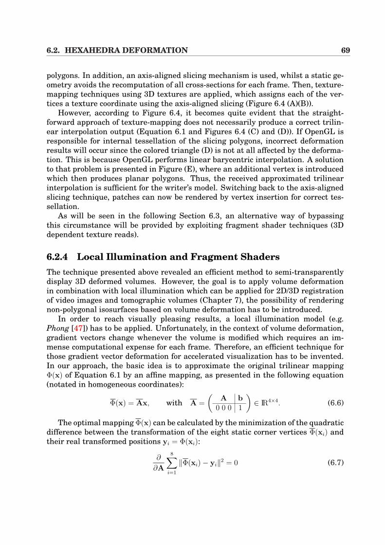
6.2. HEXAHEDRA DEFORMATION 69
polygons. In addition, an axis-aligned slicing mechanism is used, whilst a static ge-ometry avoids the recomputation of all cross-sections for each frame. Then, texture-mapping techniques using 3D textures are applied, which assigns each of the ver-tices a texture coordinate using the axis-aligned slicing (Figure 6.4 (A)(B)).
However, according to Figure 6.4, it becomes quite evident that the straight-forward approach of texture-mapping does not necessarily produce a correct trilin-ear interpolation output (Equation 6.1 and Figures 6.4 (C) and (D)). If OpenGL isresponsible for internal tessellation of the slicing polygons, incorrect deformationresults will occur since the colored triangle (D) is not at all affected by the deforma-tion. This is because OpenGL performs linear barycentric interpolation. A solutionto that problem is presented in Figure (E), where an additional vertex is introducedwhich then produces planar polygons. Thus, the received approximated trilinearinterpolation is sufficient for the writer’s model. Switching back to the axis-alignedslicing technique, patches can now be rendered by vertex insertion for correct tes-sellation.
As will be seen in the following Section 6.3, an alternative way of bypassingthis circumstance will be provided by exploiting fragment shader techniques (3Ddependent texture reads).
6.2.4 Local Illumination and Fragment ShadersThe technique presented above revealed an efficient method to semi-transparentlydisplay 3D deformed volumes. However, the goal is to apply volume deformationin combination with local illumination which can be applied for 2D/3D registrationof video images and tomographic volumes (Chapter 7), the possibility of renderingnon-polygonal isosurfaces based on volume deformation has to be introduced.
In order to reach visually pleasing results, a local illumination model (e.g.Phong [47]) has to be applied. Unfortunately, in the context of volume deformation,gradient vectors change whenever the volume is modified which requires an im-mense computational expense for each frame. Therefore, an efficient technique forthose gradient vector deformation for accelerated visualization has to be invented.In our approach, the basic idea is to approximate the original trilinear mappingΦ(x) of Equation 6.1 by an affine mapping, as presented in the following equation(notated in homogeneous coordinates):
Φ(x) = Ax, with A =
(A b
0 0 0 1
)∈ IR4×4. (6.6)
The optimal mapping Φ(x) can be calculated by the minimization of the quadraticdifference between the transformation of the eight static corner vertices Φ(xi) andtheir real transformed positions yi = Φ(xi):
∂
∂A
8∑i=1
‖Φ(xi)− yi‖2 = 0 (6.7)
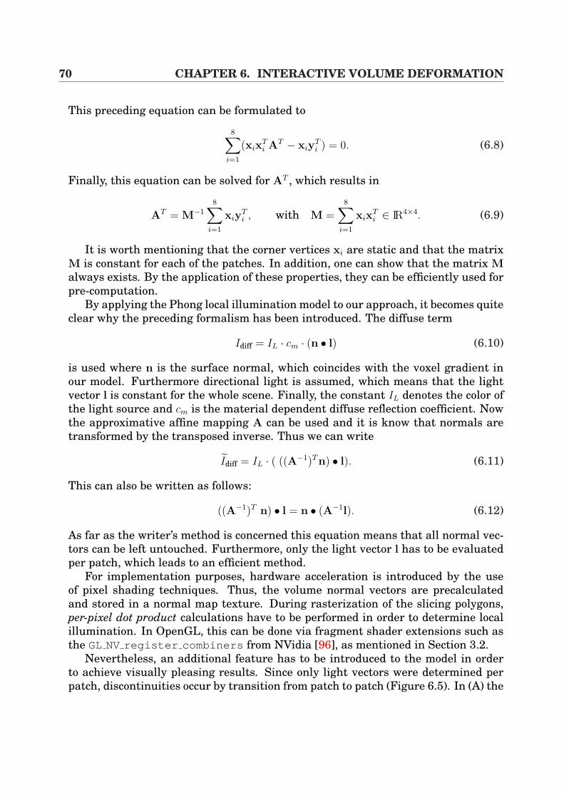
70 CHAPTER 6. INTERACTIVE VOLUME DEFORMATION
This preceding equation can be formulated to
8∑i=1
(xixTi AT − xiy
Ti ) = 0. (6.8)
Finally, this equation can be solved for AT , which results in
AT = M−1
8∑i=1
xiyTi , with M =
8∑i=1
xixTi ∈ IR4×4. (6.9)
It is worth mentioning that the corner vertices xi are static and that the matrixM is constant for each of the patches. In addition, one can show that the matrix Malways exists. By the application of these properties, they can be efficiently used forpre-computation.
By applying the Phong local illumination model to our approach, it becomes quiteclear why the preceding formalism has been introduced. The diffuse term
Idiff = IL · cm · (n • l) (6.10)
is used where n is the surface normal, which coincides with the voxel gradient inour model. Furthermore directional light is assumed, which means that the lightvector l is constant for the whole scene. Finally, the constant IL denotes the color ofthe light source and cm is the material dependent diffuse reflection coefficient. Nowthe approximative affine mapping A can be used and it is know that normals aretransformed by the transposed inverse. Thus we can write
Idiff = IL · ( ((A−1)Tn) • l). (6.11)
This can also be written as follows:
((A−1)T n) • l = n • (A−1l). (6.12)
As far as the writer’s method is concerned this equation means that all normal vec-tors can be left untouched. Furthermore, only the light vector l has to be evaluatedper patch, which leads to an efficient method.
For implementation purposes, hardware acceleration is introduced by the useof pixel shading techniques. Thus, the volume normal vectors are precalculatedand stored in a normal map texture. During rasterization of the slicing polygons,per-pixel dot product calculations have to be performed in order to determine localillumination. In OpenGL, this can be done via fragment shader extensions such asthe GL NV register combiners from NVidia [96], as mentioned in Section 3.2.
Nevertheless, an additional feature has to be introduced to the model in orderto achieve visually pleasing results. Since only light vectors were determined perpatch, discontinuities occur by transition from patch to patch (Figure 6.5). In (A) the
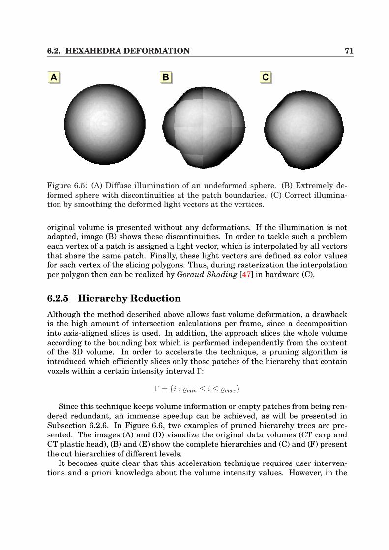
6.2. HEXAHEDRA DEFORMATION 71
AA AB AC
Figure 6.5: (A) Diffuse illumination of an undeformed sphere. (B) Extremely de-formed sphere with discontinuities at the patch boundaries. (C) Correct illumina-tion by smoothing the deformed light vectors at the vertices.
original volume is presented without any deformations. If the illumination is notadapted, image (B) shows these discontinuities. In order to tackle such a problemeach vertex of a patch is assigned a light vector, which is interpolated by all vectorsthat share the same patch. Finally, these light vectors are defined as color valuesfor each vertex of the slicing polygons. Thus, during rasterization the interpolationper polygon then can be realized by Goraud Shading [47] in hardware (C).
6.2.5 Hierarchy ReductionAlthough the method described above allows fast volume deformation, a drawbackis the high amount of intersection calculations per frame, since a decompositioninto axis-aligned slices is used. In addition, the approach slices the whole volumeaccording to the bounding box which is performed independently from the contentof the 3D volume. In order to accelerate the technique, a pruning algorithm isintroduced which efficiently slices only those patches of the hierarchy that containvoxels within a certain intensity interval Γ:
Γ = i : %min ≤ i ≤ %max
Since this technique keeps volume information or empty patches from being ren-dered redundant, an immense speedup can be achieved, as will be presented inSubsection 6.2.6. In Figure 6.6, two examples of pruned hierarchy trees are pre-sented. The images (A) and (D) visualize the original data volumes (CT carp andCT plastic head), (B) and (E) show the complete hierarchies and (C) and (F) presentthe cut hierarchies of different levels.
It becomes quite clear that this acceleration technique requires user interven-tions and a priori knowledge about the volume intensity values. However, in the
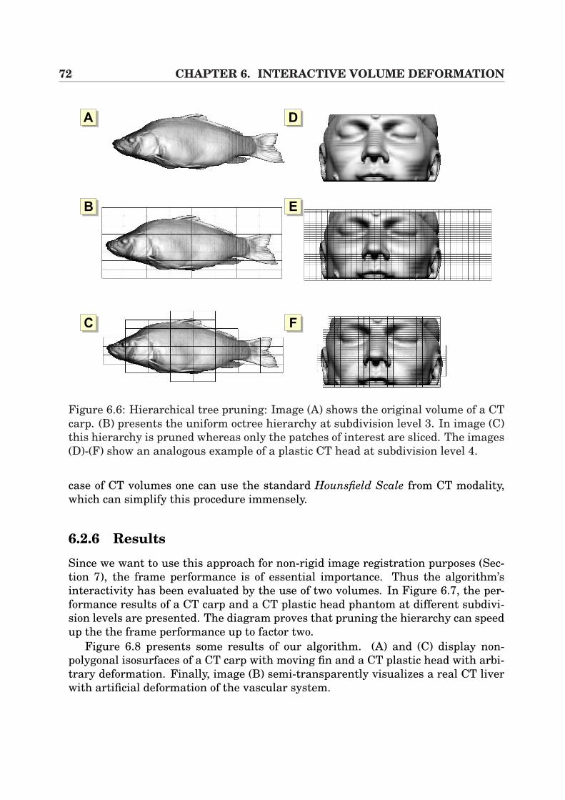
72 CHAPTER 6. INTERACTIVE VOLUME DEFORMATION
AA
AB
AC
AD
AE
AF
Figure 6.6: Hierarchical tree pruning: Image (A) shows the original volume of a CTcarp. (B) presents the uniform octree hierarchy at subdivision level 3. In image (C)this hierarchy is pruned whereas only the patches of interest are sliced. The images(D)-(F) show an analogous example of a plastic CT head at subdivision level 4.
case of CT volumes one can use the standard Hounsfield Scale from CT modality,which can simplify this procedure immensely.
6.2.6 Results
Since we want to use this approach for non-rigid image registration purposes (Sec-tion 7), the frame performance is of essential importance. Thus the algorithm’sinteractivity has been evaluated by the use of two volumes. In Figure 6.7, the per-formance results of a CT carp and a CT plastic head phantom at different subdivi-sion levels are presented. The diagram proves that pruning the hierarchy can speedup the the frame performance up to factor two.
Figure 6.8 presents some results of our algorithm. (A) and (C) display non-polygonal isosurfaces of a CT carp with moving fin and a CT plastic head with arbi-trary deformation. Finally, image (B) semi-transparently visualizes a real CT liverwith artificial deformation of the vascular system.
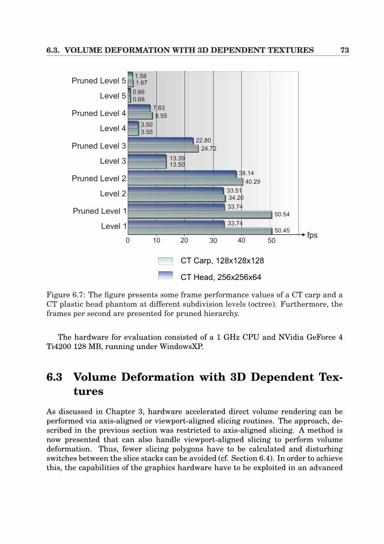
6.3. VOLUME DEFORMATION WITH 3D DEPENDENT TEXTURES 73
Pruned Level 1
Level 1
CT Carp, 128x128x128
CT Head, 256x256x64
0 10 20 30 40 50fps
Pruned Level 2
Level 2
Pruned Level 3
Level 3
Pruned Level 4
Level 4
Pruned Level 5
Level 5
1.581.67
0.66
0.68
7.63
8.55
3.50
3.55
22.80
24.72
13.3913.50
38.14
40.29
33.51
34.20
50.54
33.74
33,74
50.45
Figure 6.7: The figure presents some frame performance values of a CT carp and aCT plastic head phantom at different subdivision levels (octree). Furthermore, theframes per second are presented for pruned hierarchy.
The hardware for evaluation consisted of a 1 GHz CPU and NVidia GeForce 4Ti4200 128 MB, running under WindowsXP.
6.3 Volume Deformation with 3D Dependent Tex-tures
As discussed in Chapter 3, hardware accelerated direct volume rendering can beperformed via axis-aligned or viewport-aligned slicing routines. The approach, de-scribed in the previous section was restricted to axis-aligned slicing. A method isnow presented that can also handle viewport-aligned slicing to perform volumedeformation. Thus, fewer slicing polygons have to be calculated and disturbingswitches between the slice stacks can be avoided (cf. Section 6.4). In order to achievethis, the capabilities of the graphics hardware have to be exploited in an advanced
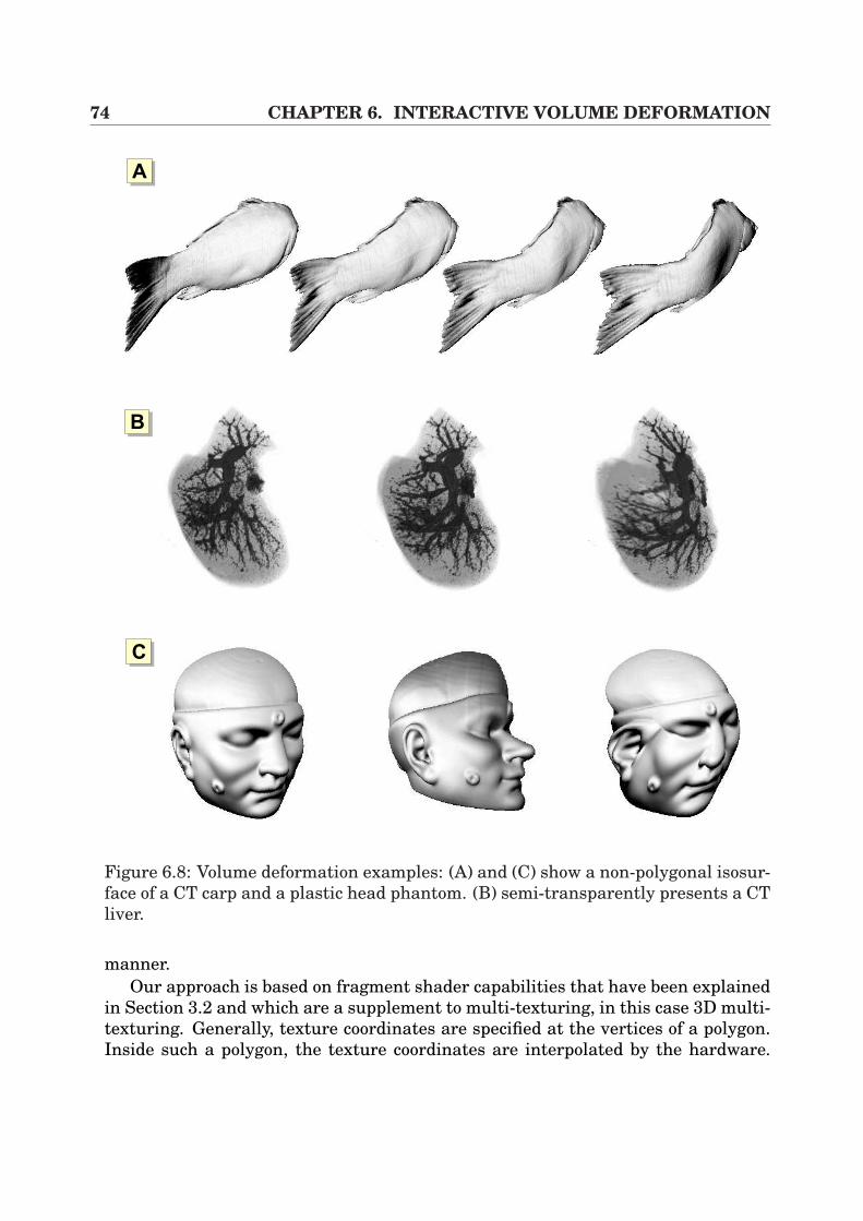
74 CHAPTER 6. INTERACTIVE VOLUME DEFORMATION
AA
AB
AC
Figure 6.8: Volume deformation examples: (A) and (C) show a non-polygonal isosur-face of a CT carp and a plastic head phantom. (B) semi-transparently presents a CTliver.
manner.Our approach is based on fragment shader capabilities that have been explained
in Section 3.2 and which are a supplement to multi-texturing, in this case 3D multi-texturing. Generally, texture coordinates are specified at the vertices of a polygon.Inside such a polygon, the texture coordinates are interpolated by the hardware.
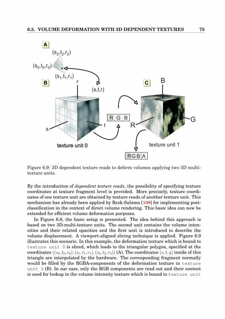
6.3. VOLUME DEFORMATION WITH 3D DEPENDENT TEXTURES 75
texture unit 1
AA
texture unit 0texture unit 0texture unit 0
r
s
B
tG
RR G B
RG B A
(s,t,r)
(s ,t ,r0 0 0)
(s ,t ,r2 2 2)
(s ,t ,r1 1 1)
AB AC
Figure 6.9: 3D dependent texture reads to deform volumes applying two 3D multi-texture units.
By the introduction of dependent texture reads, the possibility of specifying texturecoordinates at texture fragment level is provided. More precisely, texture coordi-nates of one texture unit are obtained by texture reads of another texture unit. Thismechanism has already been applied by Rezk-Salama [108] for implementing post-classification in the context of direct volume rendering. This basic idea can now beextended for efficient volume deformation purposes.
In Figure 6.9, the basic setup is presented. The idea behind this approach isbased on two 3D-multi-texture units. The second unit contains the volume inten-sities and their related opacities and the first unit is introduced to describe thevolume displacement. A viewport-aligned slicing technique is applied. Figure 6.9illustrates this scenario. In this example, the deformation texture which is bound totexture unit 0 is sliced, which leads to the triangular polygon, specified at thecoordinates ((s0, t0, r0), (s1, t1, r1), (s2, t2, r2)) (A). The coordinates (s, t, q) inside of thistriangle are interpolated by the hardware. The corresponding fragment normallywould be filled by the RGBA-components of the deformation texture in textureunit 0 (B). In our case, only the RGB components are read out and their contentis used for lookup in the volume intensity texture which is bound to texture unit
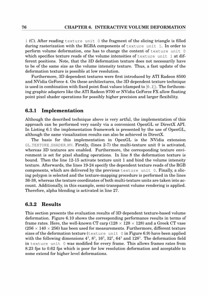
76 CHAPTER 6. INTERACTIVE VOLUME DEFORMATION
1 (C). After reading texture unit 0 the fragment of the slicing triangle is filledduring rasterization with the RGBA components of texture unit 1 . In order toperform volume deformation, one has to change the content of texture unit 0which specifies texture reads of the volume intensities of texture unit 1 at dif-ferent positions. Note, that the 3D deformation texture does not necessarily haveto be of the same size as the volume intensity texture. Thus, a fast update of thedeformation texture is possible at low resolution.
Furthermore, 3D dependent textures were first introduced by ATI Radeon 8500and NVidia GeForce 4. On these architectures, the 3D dependent texture techniqueis used in combination with fixed point float values (clamped to [0..1]). The forthcom-ing graphic adapters like the ATI Radeon 9700 or NVidia GeForce FX allow floatingpoint pixel shader operations for possibly higher precision and larger flexibility.
6.3.1 ImplementationAlthough the described technique above is very artful, the implementation of thisapproach can be performed very easily via a convenient OpenGL or DirectX API.In Listing 6.1 the implementation framework is presented by the use of OpenGL,although the same visualization results can also be achieved in DirectX.
The basis for this implementation in OpenGL is the NVidia extensionGL TEXTURESHADERNV. Firstly, (lines 2-7) the multi-texture unit 0 is activated,whereas 3D textures are enabled. Furthermore, the corresponding texture envi-ronment is set for pixel shading operations. In line 8 the deformation texture isbound. Then the line 12-15 activate texture unit 1 and bind the volume intensitytexture. Afterwards, the lines 19-24 specify the dependent texture reads of the RGBcomponents, which are delivered by the previous texture unit 0 . Finally, a slic-ing polygon is selected and the texture-mapping procedure is performed in the lines36-38, whereas the texture coordinates of both multi-texture units are taken into ac-count. Additionally, in this example, semi-transparent volume rendering is applied.Therefore, alpha blending is activated in line 27.
6.3.2 ResultsThis section presents the evaluation results of 3D dependent texture-based volumedeformation. Figure 6.10 shows the corresponding performance results in terms offrame rates. Here, the well-known CT carp (128 × 128 × 128) and a Greek CT vase(256 × 140 × 256) has been used for measurements. Furthermore, different texturesizes of the deformation texture (texture unit 0 in Figure 6.9) have been appliedwith the following dimensions 43, 83, 163, 323, 643 and 1283. The deformation fieldin texture unit 0 was modified for every frame. This allows frames rates from8.23 fps to 0.62 fps which is poor for low resolution deformation and acceptable tosome extend for higher level deformations.
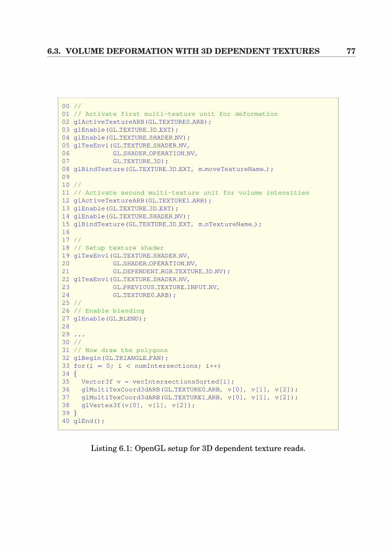
6.3. VOLUME DEFORMATION WITH 3D DEPENDENT TEXTURES 77
00 //01 // Activate first multi-texture unit for deformation02 glActiveTextureARB(GL TEXTURE0ARB);03 glEnable(GL TEXTURE3D EXT);04 glEnable(GL TEXTURESHADERNV);05 glTexEnvi(GL TEXTURESHADERNV,06 GL SHADEROPERATIONNV,07 GL TEXTURE3D);08 glBindTexture(GL TEXTURE3D EXT, m moveTextureName );0910 //11 // Activate second multi-texture unit for volume intensities12 glActiveTextureARB(GL TEXTURE1ARB);13 glEnable(GL TEXTURE3D EXT);14 glEnable(GL TEXTURESHADERNV);15 glBindTexture(GL TEXTURE3D EXT, m nTextureName );1617 //18 // Setup texture shader19 glTexEnvi(GL TEXTURESHADERNV,20 GL SHADEROPERATIONNV,21 GL DEPENDENTRGBTEXTURE3D NV);22 glTexEnvi(GL TEXTURESHADERNV,23 GL PREVIOUSTEXTUREINPUT NV,24 GL TEXTURE0ARB);25 //26 // Enable blending27 glEnable(GL BLEND);2829 ...30 //31 // Now draw the polygons32 glBegin(GL TRIANGLE FAN);33 for(i = 0; i < numIntersections; i++)34 35 Vector3f v = vecIntersectionsSorted[i];36 glMultiTexCoord3dARB(GL TEXTURE0ARB, v[0], v[1], v[2]);37 glMultiTexCoord3dARB(GL TEXTURE1ARB, v[0], v[1], v[2]);38 glVertex3f(v[0], v[1], v[2]);39 40 glEnd();
Listing 6.1: OpenGL setup for 3D dependent texture reads.
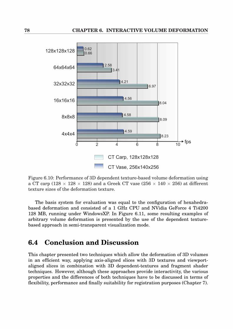
78 CHAPTER 6. INTERACTIVE VOLUME DEFORMATION
CT Carp, 128x128x128
CT Vase, 256x140x256
0 2 4 6 8 10fps
128x128x128
64x64x64
32x32x32
16x16x16
8x8x8
4x4x48.23
8.09
8.04
6.97
3.41
0.66
0.62
2.58
4.21
4.56
4.58
4.59
Figure 6.10: Performance of 3D dependent texture-based volume deformation usinga CT carp (128 × 128 × 128) and a Greek CT vase (256 × 140 × 256) at differenttexture sizes of the deformation texture.
The basis system for evaluation was equal to the configuration of hexahedra-based deformation and consisted of a 1 GHz CPU and NVidia GeForce 4 Ti4200128 MB, running under WindowsXP. In Figure 6.11, some resulting examples ofarbitrary volume deformation is presented by the use of the dependent texture-based approach in semi-transparent visualization mode.
6.4 Conclusion and DiscussionThis chapter presented two techniques which allow the deformation of 3D volumesin an efficient way, applying axis-aligned slices with 3D textures and viewport-aligned slices in combination with 3D dependent-textures and fragment shadertechniques. However, although these approaches provide interactivity, the variousproperties and the differences of both techniques have to be discussed in terms offlexibility, performance and finally suitability for registration purposes (Chapter 7).
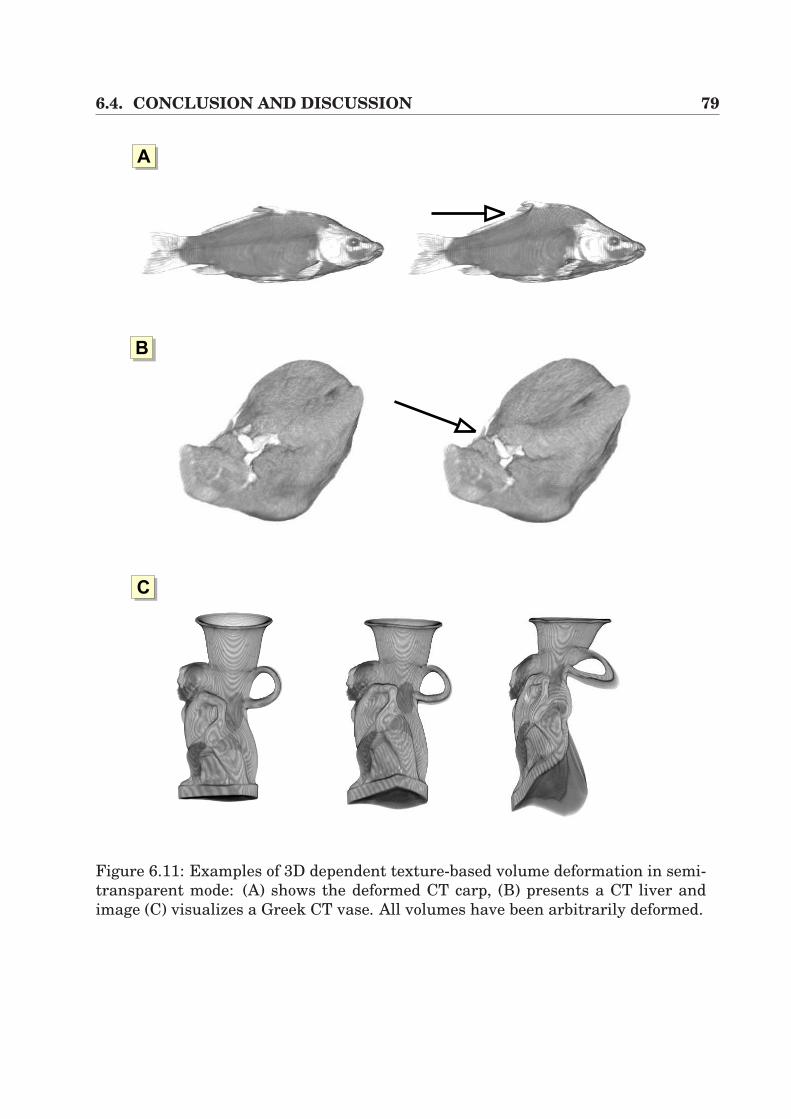
6.4. CONCLUSION AND DISCUSSION 79
AA
AB
AC
Figure 6.11: Examples of 3D dependent texture-based volume deformation in semi-transparent mode: (A) shows the deformed CT carp, (B) presents a CT liver andimage (C) visualizes a Greek CT vase. All volumes have been arbitrarily deformed.
80 CHAPTER 6. INTERACTIVE VOLUME DEFORMATION
As far as the flexibility of the underlying model is concerned, it becomes quite ev-ident that dependent texture reads are superior to the hexahedra approach, whichrequires a hierarchical octree model in order to deform 3D volumes. Thus, a lotof overhead has to be considered which hampers the integration of flexible higher-order deformation models such as spline interpolation or models based on physi-cal material behavior, described by partial differential equations (e.g. mass-springmodels, viscosity simulation). Furthermore, the dependent texture-based approachis more suitable for such methods since every element of the deformation texturecan be picked and individually displaced.
By taking into account the frame performance of the two approaches, the resultis vice-versa. Figures 6.7 and 6.11 prove very clearly that hexahedra deformation isthe more powerful method. Especially when using lower resolutions of the under-lying deformation model, around 8 fps (dependent textures) have to be faced with50 fps (hexahedra approach). However, by heavily increasing the deformation reso-lution, dependent texture reads become more and more interesting. As can be seenfrom the figures, the highest measured resolution at 1283 free elements achieves0.66 fps. Using high resolution in terms of hexahedra deformation, the highest levelof detail allows 313 free elements.
As mentioned at the beginning of this chapter, the aim is to find an algorithmwhich is suitable for fast 2D/3D registration. In this context, hexahedra-based de-formation is the chosen approach for further implementations. Although the depen-dent texture-based approach contains the more artful underlying model and pro-vides greater flexibility in terms of integration of higher-order models, the reducedframe performance plays an important role for the application of hexahedra defor-mation for registration purposes. However, hexahedra deformation includes somedrawbacks as discussed previously. Since we use an axis-aligned slicing algorithm,image artifacts can occur by switching between the slicing directions. Fortunately,this drawback can be immensely reduced by increasing the number of slices. Fur-thermore, the model contains small mathematical errors, generated by the inversetrilinear mapping of the vertex translation and the interpolation of the light vectorsat the vertices, sharing several patches. However, as will be seen in the next chap-ter, the achieved accuracy applying hexahedra deformation in terms of registrationwill be good enough for our purposes.
Chapter 7
Non-rigid 2D/3D Registration ofVideo Images and CT
In the previous chapters, rigid transformations were applied in order to relate pre-operative 3D CT volumes to the patient space. Although this technique allows thecalculation of robust and fast image overlay in the context of augmented realityusing anatomical or fiducial markers, those methods suffer from the limitation thatsoft-tissue deformation cannot be considered.
Recent medical research projects in the context of open liver interventions andimage-guided surgery proved that there is an increasing need for considering soft-tissue deformation. This interesting problem is well-known and often investigatedin neurosurgical applications handling the brain shift phenomenon and is becomingmore and more important for liver intervention research.
In the following sections, a basic algorithm for non-rigid 2D/3D registration thatkeeps track of soft-tissue deformation by the use of multiple-view video images andpre-operative 3D CT data is introduced. In this context, the technique for inter-active volume deformation of Section 6.2 is applied in order to generate arbitrarysynthetic views. Since conventional 2D/3D registration approaches mostly use sur-face renderings based on triangle meshes, inner volumetric structures that directlydefine the shape of an object cannot be considered. By the use of our deformablevolume rendering approach, the surface that is to be matched to the video images,is directly determined by inner structures of the CT volume at interactive framerates. By the application of an intensity-based registration algorithm, robust non-rigid registration results can be achieved.
This chapter is organized as follows. In Section 7.1 some relevant previous workis laid out that also tries to non-linearly match intra-operative video images to CTdata. The following Section 7.2 briefly describes the calibration and navigation thatis necessary for the registration. Afterwards, Section 7.3 introduces the image-based registration technique in order to adapt 3D CT data to video images, whilstSection 7.4 presents a higher-order deformation model that is used to simulate soft-tissue behavior during the registration process. Finally, the results are depicted in
82 CHAPTER 7. NON-RIGID 2D/3D REGISTRATION
Section 7.5. Section 7.6 contains a conclusion to this chapter.
7.1 Previous Work2D/3D registration can be principally divided into landmark-based, contour-basedand intensity-based techniques. This technique has often been used to assist physi-cians, when orientational aid is needed at the time of intervention. Especially inradiological treatments like the well-known catheter navigation, standard 2D X-ray, portal or fluoroscopic images often have been registered to 3D CTA or MRAimages [6, 72, 55]. The drawback of such methods often is the need of explicit seg-mentation. Furthermore, in order to generate the synthetic view for registration,time consuming digital reconstructed radiographs (DRR) are necessary for registra-tion.
In order to accelerate the rendering time for DRRs, Goecke et al. [51] appliedthe shear-warp factorization [76] which has already been discussed in Section 3.1.Following this, the synthetic images are compared to real images by the use ofintensity-based metrics. Another hardware-based registration acceleration is in-troduced by Hastreiter et al., who uses registers of the graphics hardware for fastmetric measurements in the context of rigid 3D/3D registration [58].
However, the approaches above predominantly apply single-view images in orderto match them to the synthetic view. Therefore, the algorithms have been extendedto multiple-view approaches [26, 80]. Clarkson et al. [26] generate synthetic viewsby standard surface renderings and compare them to multiple video images. Afteran initial starting pose of the synthetic view, mutual information [148] is appliedin order to maximize the similarity of a pair of video image and synthetic view.This procedure is fulfilled for all pairs of images and surface renderings, whereasan optimization procedure varies the translational and rotational parameters of thesynthetic views. Furthermore, the transitions between the different video imagesare known.
All those methods have the common feature, that they rigidly register 2D infor-mation (video and X-ray images) to pre-operative CT data. In order to be able toconsider soft-tissue deformation, a new collection of techniques has arisen in recentmonths [147, 89, 22] applying additional hardware for registration purposes. Vet-ter et al. [147] utilize Doppler ultrasound and electro-magnetic navigation in openliver surgery, whilst the navigated ultrasound transducer generates a 3D image ofthe fixed liver. Then, vascular bifurcations are applied for non-rigid registrationto the pre-operative CT. Following this, small tracking sensors are attached to theliver. Afterwards, the liver fixation is withdrawn and the tissue deformation can betracked via the electro-magnetic sensors. This system is at an experimental stageand still includes high inaccuracies.
A further system for open liver surgery has been developed by Cash and Migaet al. [89, 22] applying a 3D laser range scanner for liver surface generation. As a
7.2. CALIBRATION AND NAVIGATION 83
first step, rigid registration of the pre-operative liver isosurface and scanned surfaceis performed via an ICP algorithm [10]. Afterwards, a 3D finite element modeling(FEM) fits the volumes in a non-linear way.
However, this work focuses on non-rigid registration techniques that are basedon intensity similarities. As far as the writer is aware, this idea of non-rigid regis-tration is completely new. This work fundamentally extends the work by Clarksonet al. [26] to non-rigid registration by the introduction of our fast deformable volumerendering approach, presented in the previous chapter.
7.2 Calibration and NavigationFirst of all, the correct rendering for each of the video images has to be generated.Therefore, the used camera has to be calibrated. The techniques presented in Sec-tion 4.3.1 are applied in order to achieve the intrinsic parameters that define theviewing frustum for rendering. In addition, since the optical lens properties of theemployed camera remain static, this procedure has to be performed only once in apreprocessing step.
In this context, the extrinsic camera parameters that describe the pose are ofhigh importance. An electro-magnetic navigation system is used, the sensor ofwhich is attached to the camera. The setup for sensor calibration is described inSection 4.4.
7.3 RegistrationIn order to register multiple-view video images of an object to their synthetic views,a two tier registration procedure is introduced. On the assumption that objects de-form only non-linearly in shape, we can compensate the translation and the rotationof objects by a rigid-body registration. Applying fiducial or anatomical landmarks,the same registration steps as presented in Section 4.5.1 are performed. This proce-dure brings us very close to the final registration result, since it is assumed, that theobject now can only deform non-linearly. The remaining registration error can thenbe minimized using our 2D/3D registration algorithm which is based on similaritymeasurement.
Figure 7.1 presents enlargements of both a video image and its correspondingsynthetic view. It becomes quite evident that the visible grey value intensities can beapplied in order to determine similarity of two images. This observation will now beused for non-rigid 2D/3D registration in which a video image of an object is directlycompared against its synthetic projection in terms of direct volume rendering of theCT.
In this context, the choice of a similarity metric which robustly allows the mea-surement of the similarity of two images has deep impact on the registration results.
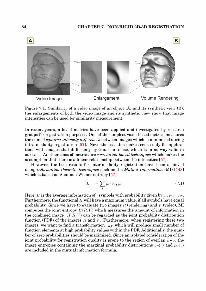
84 CHAPTER 7. NON-RIGID 2D/3D REGISTRATION
Video Image Volume RenderingEnlargement
AA AB
Figure 7.1: Similarity of a video image of an object (A) and its synthetic view (B):the enlargements of both the video image and its synthetic view show that imageintensities can be used for similarity measurement.
In recent years, a lot of metrics have been applied and investigated by researchgroups for registration purposes. One of the simplest voxel-based metrics measuresthe sum of squared intensity differences between images which is minimized duringintra-modality registration [57]. Nevertheless, this makes sense only for applica-tions with images that differ only by Gaussian noise, which is in no way valid inour case. Another class of metrics are correlation-based techniques which makes theassumption that there is a linear relationship between the intensities [57].
However, the best results for inter-modality registration have been achievedusing information theoretic techniques such as the Mutual Information (MI) [148]which is based on Shannon-Wiener entropy [57]
H = −∑
i
pi · log pi. (7.1)
Here, H is the average information of i symbols with probability given by p1, p2, ..., pi.Furthermore, the functional H will have a maximum value, if all symbols have equalprobability. Since we have to evaluate two images R (rendering) and V (video), MIcomputes the joint entropy H(R, V ) which measures the amount of information inthe combined image. H(R, V ) can be regarded as the joint probability distributionfunction (PDF) of the images R and V . Furthermore, when registering these twoimages, we want to find a transformation τR,V which will produce small number offunction elements at high probability values within the PDF. Additionally, the num-ber of zero probabilities should be maximized. Since an isolated consideration of thejoint probability for registration quality is prone to the region of overlap ΩR,V , theimage entropies containing the marginal probability distributions pR(r) and pV (v)are included in the mutual information formula.
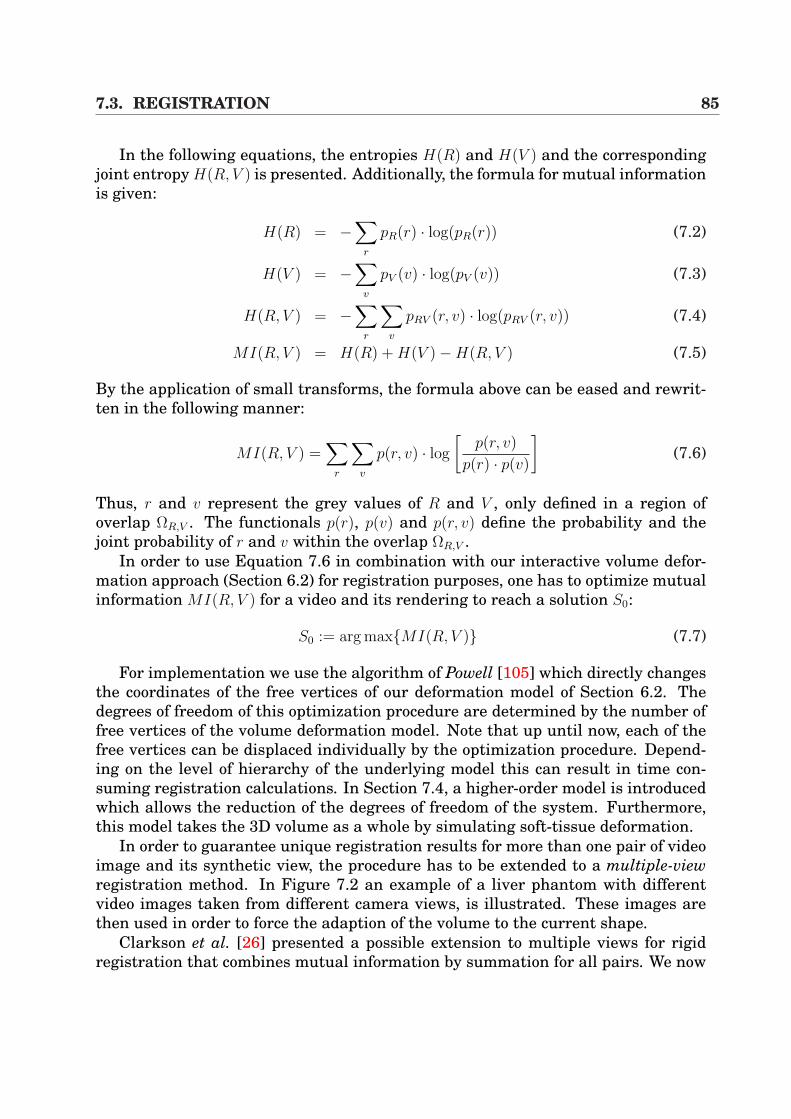
7.3. REGISTRATION 85
In the following equations, the entropies H(R) and H(V ) and the correspondingjoint entropy H(R, V ) is presented. Additionally, the formula for mutual informationis given:
H(R) = −∑
r
pR(r) · log(pR(r)) (7.2)
H(V ) = −∑
v
pV (v) · log(pV (v)) (7.3)
H(R, V ) = −∑
r
∑v
pRV (r, v) · log(pRV (r, v)) (7.4)
MI(R, V ) = H(R) + H(V )−H(R, V ) (7.5)
By the application of small transforms, the formula above can be eased and rewrit-ten in the following manner:
MI(R, V ) =∑
r
∑v
p(r, v) · log
[p(r, v)
p(r) · p(v)
](7.6)
Thus, r and v represent the grey values of R and V , only defined in a region ofoverlap ΩR,V . The functionals p(r), p(v) and p(r, v) define the probability and thejoint probability of r and v within the overlap ΩR,V .
In order to use Equation 7.6 in combination with our interactive volume defor-mation approach (Section 6.2) for registration purposes, one has to optimize mutualinformation MI(R, V ) for a video and its rendering to reach a solution S0:
S0 := arg maxMI(R, V ) (7.7)
For implementation we use the algorithm of Powell [105] which directly changesthe coordinates of the free vertices of our deformation model of Section 6.2. Thedegrees of freedom of this optimization procedure are determined by the number offree vertices of the volume deformation model. Note that up until now, each of thefree vertices can be displaced individually by the optimization procedure. Depend-ing on the level of hierarchy of the underlying model this can result in time con-suming registration calculations. In Section 7.4, a higher-order model is introducedwhich allows the reduction of the degrees of freedom of the system. Furthermore,this model takes the 3D volume as a whole by simulating soft-tissue deformation.
In order to guarantee unique registration results for more than one pair of videoimage and its synthetic view, the procedure has to be extended to a multiple-viewregistration method. In Figure 7.2 an example of a liver phantom with differentvideo images taken from different camera views, is illustrated. These images arethen used in order to force the adaption of the volume to the current shape.
Clarkson et al. [26] presented a possible extension to multiple views for rigidregistration that combines mutual information by summation for all pairs. We now
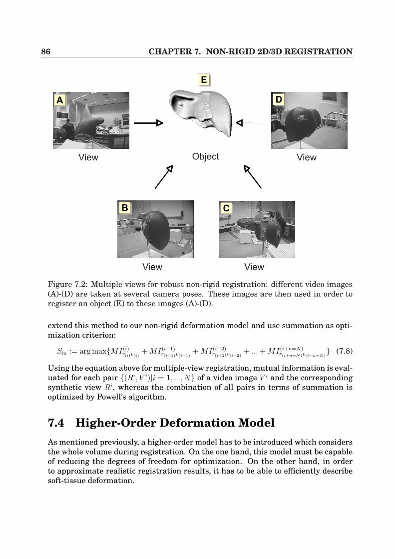
86 CHAPTER 7. NON-RIGID 2D/3D REGISTRATION
View
View View
ViewObject
AA
AB AC
AD
AE
Figure 7.2: Multiple views for robust non-rigid registration: different video images(A)-(D) are taken at several camera poses. These images are then used in order toregister an object (E) to these images (A)-(D).
extend this method to our non-rigid deformation model and use summation as opti-mization criterion:
Sm := arg maxMI(i)r(i)v(i)
+ MI(i+1)r(i+1)v(i+1)
+ MI(i+2)r(i+2)v(i+2)
+ ... + MI(i+n=N)r(i+n=N)v(i+n=N)
(7.8)
Using the equation above for multiple-view registration, mutual information is eval-uated for each pair (Ri, V i)|i = 1, ..., N of a video image V i and the correspondingsynthetic view Ri, whereas the combination of all pairs in terms of summation isoptimized by Powell’s algorithm.
7.4 Higher-Order Deformation ModelAs mentioned previously, a higher-order model has to be introduced which considersthe whole volume during registration. On the one hand, this model must be capableof reducing the degrees of freedom for optimization. On the other hand, in orderto approximate realistic registration results, it has to be able to efficiently describesoft-tissue deformation.
7.4. HIGHER-ORDER DEFORMATION MODEL 87
Thus, a very brief overview of soft-tissue model descriptions is presented in theSubsection 7.4.1. Following this, the model that has been applied in the writer’ssystem is introduced in Subsection 7.4.2.
7.4.1 OverviewRecently, a wide variety of different models to describe soft-tissue deformation havebeen published by researchers, mostly driven by image-guided surgery registrationsor surgery simulators for training purposes. Amongst these, the approaches can bedivided into the following main categories:
Registration by Splines For registration purposes in general, different corre-sponding landmarks or control points Φi are selected within the images S ∈ Iand D ∈ I ′ that are to be registered and defined in certain image spaces Iand I ′. Using these control points, a smoothly varying displacement field isinterpolated by
T(Φi) = Φ′i with i = 1, ..., n , (7.9)
where Φi denotes the location of the control points in the target image D andΦ′i represents the corresponding control points in the source image S. Alterna-
tively, control points can be regarded at equidistant spacing, forming a regularmesh.
Spline-based techniques have often been applied for image registration pur-poses in terms of Thin-Plate Splines [85, 39, 115, 128] and B-Splines [116, 97].The latter ones allow free-from deformation (FFD) and require an underlyingregular mesh of control points that is to be deformed. This produces a smoothand C2 continuous transformation of the shape of the volume.
Physically-Based Elastic Registration The basic idea behind physically-basedelastic registration is to model the deformation in terms of physical processesdescribing an elastic object such as rubber. This model consists of internal andexternal forces, whereas external forces cause the deformation (e.g. stress) andinternal forces work against external influences. Mostly, Navier linear elasticpartial differential equation (PDE) is applied in order to describe this behavior.Such an implementation is presented by Bajcsy et al. [5]. Further extensionsare presented by Davatzikos [33], Miga et al. [88] and Paulsen et al. [99], of-ten driven by brain-shift correction applications. In most cases, PDEs may besolved by finite element models (FEM) [88, 44].
Of similarity to the approaches above are mass-spring models that approx-imate soft-tissue deformation by the behavior of interacting springs. Sincethese models are computationally less expensive than FEMs, they often havebeen applied in the context of surgery simulators (for example endoscopic liversurgery simulations) [29, 73].
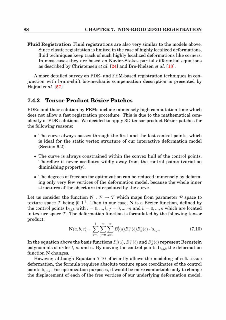
88 CHAPTER 7. NON-RIGID 2D/3D REGISTRATION
Fluid Registration Fluid registrations are also very similar to the models above.Since elastic registration is limited in the case of highly localized deformations,fluid techniques keep track of such highly localized deformations like corners.In most cases they are based on Navier-Stokes partial differential equationsas described by Christensen et al. [24] and Bro-Nielsen et al. [18].
A more detailed survey on PDE- and FEM-based registration techniques in con-junction with brain-shift bio-mechanic compensation description is presented byHajnal et al. [57].
7.4.2 Tensor Product Bezier PatchesPDEs and their solution by FEMs include immensely high computation time whichdoes not allow a fast registration procedure. This is due to the mathematical com-plexity of PDE solutions. We decided to apply 3D tensor product Bezier patches forthe following reasons:
• The curve always passes through the first and the last control points, whichis ideal for the static vertex structure of our interactive deformation model(Section 6.2).
• The curve is always constrained within the convex hull of the control points.Therefore it never oscillates wildly away from the control points (variationdiminishing property).
• The degrees of freedom for optimization can be reduced immensely by deform-ing only very few vertices of the deformation model, because the whole innerstructures of the object are interpolated by the curve.
Let us consider the function N : P 7→ T which maps from parameter P space totexture space T being [0, 1]3. Then in our case, N is a Bezier function, defined bythe control points bi,j,k with i = 0, ..., l, j = 0, ...,m and k = 0, ..., n which are locatedin texture space T . The deformation function is formulated by the following tensorproduct:
N(a, b, c) =l∑
i=0
m∑j=0
n∑
k=0
Bli(a)Bm
j (b)Bnk (c) · bi,j,k (7.10)
In the equation above the basis functions Bli(a), Bm
j (b) and Bnk (c) represent Bernstein
polynomials of order l, m and n. By moving the control points bi,j,k the deformationfunction N changes.
However, although Equation 7.10 efficiently allows the modeling of soft-tissuedeformation, the formula requires absolute texture space coordinates of the controlpoints bi,j,k. For optimization purposes, it would be more comfortable only to changethe displacement of each of the free vertices of our underlying deformation model.
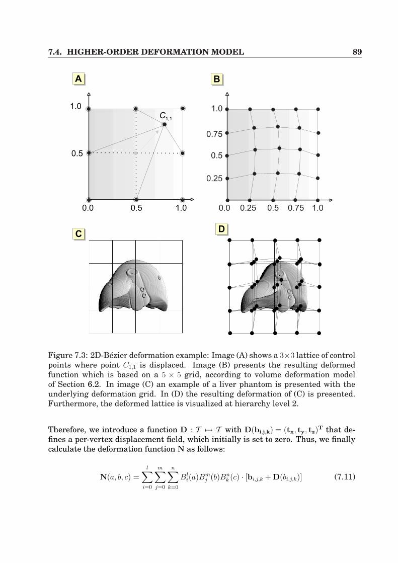
7.4. HIGHER-ORDER DEFORMATION MODEL 89
AA
1.0
0.75
0.5
1.00.750.5
0.25
0.250.01.00.50.0
1.0
0.5
AB
ACAD
C1,1
Figure 7.3: 2D-Bezier deformation example: Image (A) shows a 3×3 lattice of controlpoints where point C1,1 is displaced. Image (B) presents the resulting deformedfunction which is based on a 5 × 5 grid, according to volume deformation modelof Section 6.2. In image (C) an example of a liver phantom is presented with theunderlying deformation grid. In (D) the resulting deformation of (C) is presented.Furthermore, the deformed lattice is visualized at hierarchy level 2.
Therefore, we introduce a function D : T 7→ T with D(bi,j,k) = (tx, ty, tz)T that de-
fines a per-vertex displacement field, which initially is set to zero. Thus, we finallycalculate the deformation function N as follows:
N(a, b, c) =l∑
i=0
m∑j=0
n∑
k=0
Bli(a)Bm
j (b)Bnk (c) · [bi,j,k + D(bi,j,k)] (7.11)
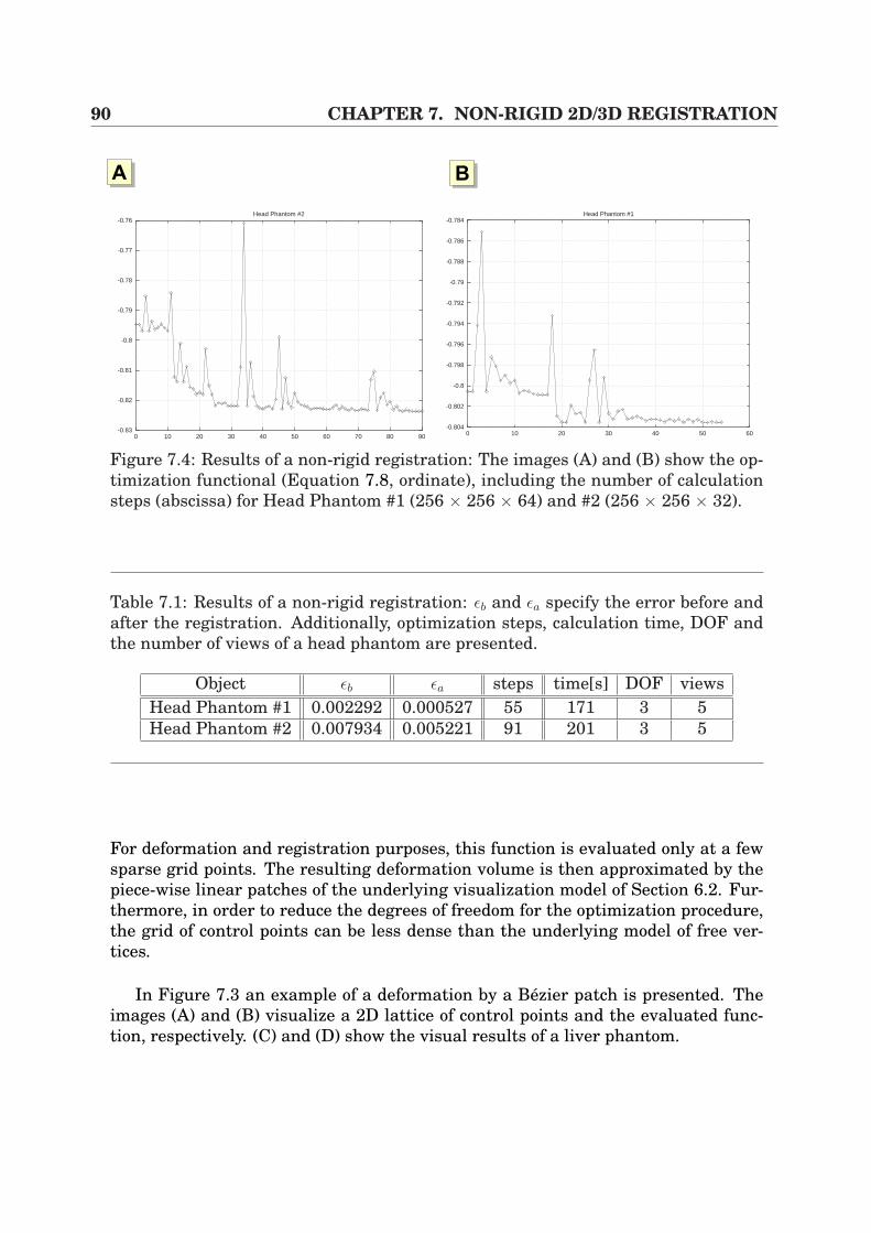
90 CHAPTER 7. NON-RIGID 2D/3D REGISTRATION
AA AB
-0.83
-0.82
-0.81
-0.8
-0.79
-0.78
-0.77
-0.76
0 10 20 30 40 50 60 70 80 90
Head Phantom #2
-0.804
-0.802
-0.8
-0.798
-0.796
-0.794
-0.792
-0.79
-0.788
-0.786
-0.784
0 10 20 30 40 50 60
Head Phantom #1
Figure 7.4: Results of a non-rigid registration: The images (A) and (B) show the op-timization functional (Equation 7.8, ordinate), including the number of calculationsteps (abscissa) for Head Phantom #1 (256 × 256 × 64) and #2 (256 × 256 × 32).
Table 7.1: Results of a non-rigid registration: εb and εa specify the error before andafter the registration. Additionally, optimization steps, calculation time, DOF andthe number of views of a head phantom are presented.
Object εb εa steps time[s] DOF viewsHead Phantom #1 0.002292 0.000527 55 171 3 5Head Phantom #2 0.007934 0.005221 91 201 3 5
For deformation and registration purposes, this function is evaluated only at a fewsparse grid points. The resulting deformation volume is then approximated by thepiece-wise linear patches of the underlying visualization model of Section 6.2. Fur-thermore, in order to reduce the degrees of freedom for the optimization procedure,the grid of control points can be less dense than the underlying model of free ver-tices.
In Figure 7.3 an example of a deformation by a Bezier patch is presented. Theimages (A) and (B) visualize a 2D lattice of control points and the evaluated func-tion, respectively. (C) and (D) show the visual results of a liver phantom.
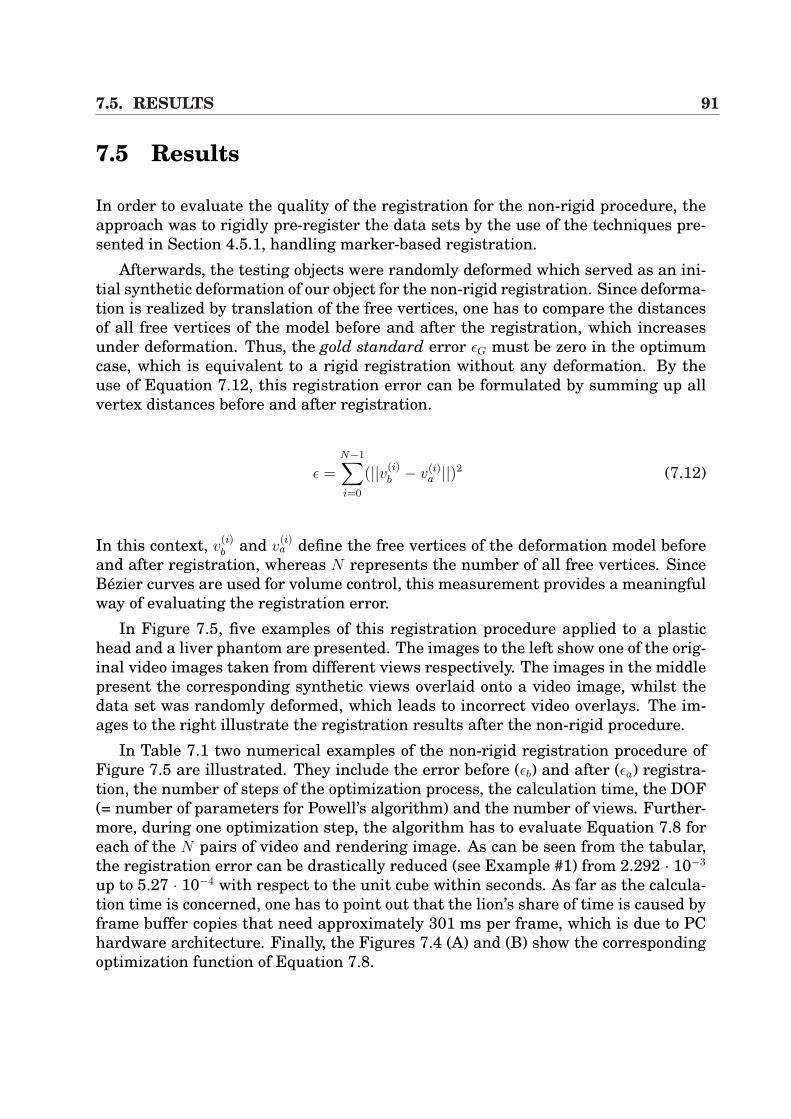
7.5. RESULTS 91
7.5 Results
In order to evaluate the quality of the registration for the non-rigid procedure, theapproach was to rigidly pre-register the data sets by the use of the techniques pre-sented in Section 4.5.1, handling marker-based registration.
Afterwards, the testing objects were randomly deformed which served as an ini-tial synthetic deformation of our object for the non-rigid registration. Since deforma-tion is realized by translation of the free vertices, one has to compare the distancesof all free vertices of the model before and after the registration, which increasesunder deformation. Thus, the gold standard error εG must be zero in the optimumcase, which is equivalent to a rigid registration without any deformation. By theuse of Equation 7.12, this registration error can be formulated by summing up allvertex distances before and after registration.
ε =N−1∑i=0
(||v(i)b − v(i)
a ||)2 (7.12)
In this context, v(i)b and v
(i)a define the free vertices of the deformation model before
and after registration, whereas N represents the number of all free vertices. SinceBezier curves are used for volume control, this measurement provides a meaningfulway of evaluating the registration error.
In Figure 7.5, five examples of this registration procedure applied to a plastichead and a liver phantom are presented. The images to the left show one of the orig-inal video images taken from different views respectively. The images in the middlepresent the corresponding synthetic views overlaid onto a video image, whilst thedata set was randomly deformed, which leads to incorrect video overlays. The im-ages to the right illustrate the registration results after the non-rigid procedure.
In Table 7.1 two numerical examples of the non-rigid registration procedure ofFigure 7.5 are illustrated. They include the error before (εb) and after (εa) registra-tion, the number of steps of the optimization process, the calculation time, the DOF(= number of parameters for Powell’s algorithm) and the number of views. Further-more, during one optimization step, the algorithm has to evaluate Equation 7.8 foreach of the N pairs of video and rendering image. As can be seen from the tabular,the registration error can be drastically reduced (see Example #1) from 2.292 · 10−3
up to 5.27 · 10−4 with respect to the unit cube within seconds. As far as the calcula-tion time is concerned, one has to point out that the lion’s share of time is caused byframe buffer copies that need approximately 301 ms per frame, which is due to PChardware architecture. Finally, the Figures 7.4 (A) and (B) show the correspondingoptimization function of Equation 7.8.
92 CHAPTER 7. NON-RIGID 2D/3D REGISTRATION
7.6 Conclusion and DiscussionIn this chapter a flexible algorithm for fast 2D/3D registration using non-rigid defor-mation has been presented. The technique allows the registration of 3D CT volumesto multiple-view video images in combination with non-polygonal isosurfaces andmutual information as image similarity metric. Moreover, the algorithm extendsthe approach presented by Clarkson et al. [26] such that non-rigid registration inrespect of volume deformation is possible. However, although this technique provesthat non-rigid 2D/3D registration can be performed considerably quickly, one hasto keep in mind that the current implementation is basic research. In particularthe fact that multiple-view video images of an object are necessary for registration,hampers the intra-operative use during intervention in minimally-invasive proce-dures. This is based on the reduced opportunity for image acquisition of the liver viatrocars (cf. Section 2.1), which are of limited availability. Thus, an unlimited camerapath around the organs of interest is not possible and this complicates our intensity-based registration procedure to guarantee unequivocal results. In constrast, openliver interventions are the more suitable applications for the presented technique,since they allow an unlimited look at the uncovered surface of the organ. Both sce-narios have the common feature that the image quality has a deep impact on theregistration results. In the case of realistic laparoscopic video images, the qualityis influenced by medical circumstances such as blood, smoke for ablation, water forcleaning the field of view and physical effects such as specular highlights. There-fore, the algorithms have to be extended to handle such negative influences. In thiscontext, a first approach to increase endoscopic image quality has been provided byVogt et al. [149] with encouraging results.
Furthermore, the technical properties of the algorithm that influence correct reg-istration results have to be discussed. As already mentioned in Section 6.2, thevisualization component of the system which generates non-polygonal isosurfaces,has been implemented such that axis-aligned slicing is applied. When switchingbetween the slicing directions, small artifacts occur. Their influence on the registra-tion can be managed by increasing the sampling rate with unrecognizable impacton the registration accuracy. Moreover, the interpolative illumination model of theunderlying hardware-based deformation model introduces small errors during reg-istrations, which are hard to investigate in terms of registration accuracy. Here,per-vertex illumination was applied by averaging the light vector of all patches thatshared that vertex. In contrast, the definition of the virtual light source has a greatimpact on the registration results. However, this factor has already been investi-gated in detail by Clarkson et al. [26]. In consequence, the setup described in thisthesis has to make sure that real and virtual light sources are as well aligned aspossible.
Although the algorithm presented in this chapter is current basic research, it hasshown very promising results in the context of non-rigid intensity-based registra-tion. In the context of further future applications, this becomes quite interesting for
7.6. CONCLUSION AND DISCUSSION 93
other registration scenarios. Here, DSA (digital subtraction angiography) , whichprovides high quality images of even small intra-cranial vessels demonstrates ahigh temporal resolution compared to standard imaging modalities like CT angiog-raphy (CTA) or MRA. Thus, important diagnostic information like early filling of anintra-cranial vein indicating arteriovenous shunting is only given by DSA, which isvery interesting for patients with vascular malformations like arteriovenous malfor-mations (AVMs) and intra-cranial aneurysms. Since it is difficult for the clinicianto relate the vascular findings within the DSA, a fusion between 3D information(CTA, MRA) and 2D information (DSA) is of increasing interest. By the applicationof the presented algorithm, our approach could present an important basic workin order to reach such aims, since deformations occur in the images. Furthermore,fast registration times are an essential need for intra-operative use. In combinationwith our technique and the presented calculation time, the algorithm could providea promising preparatory work.
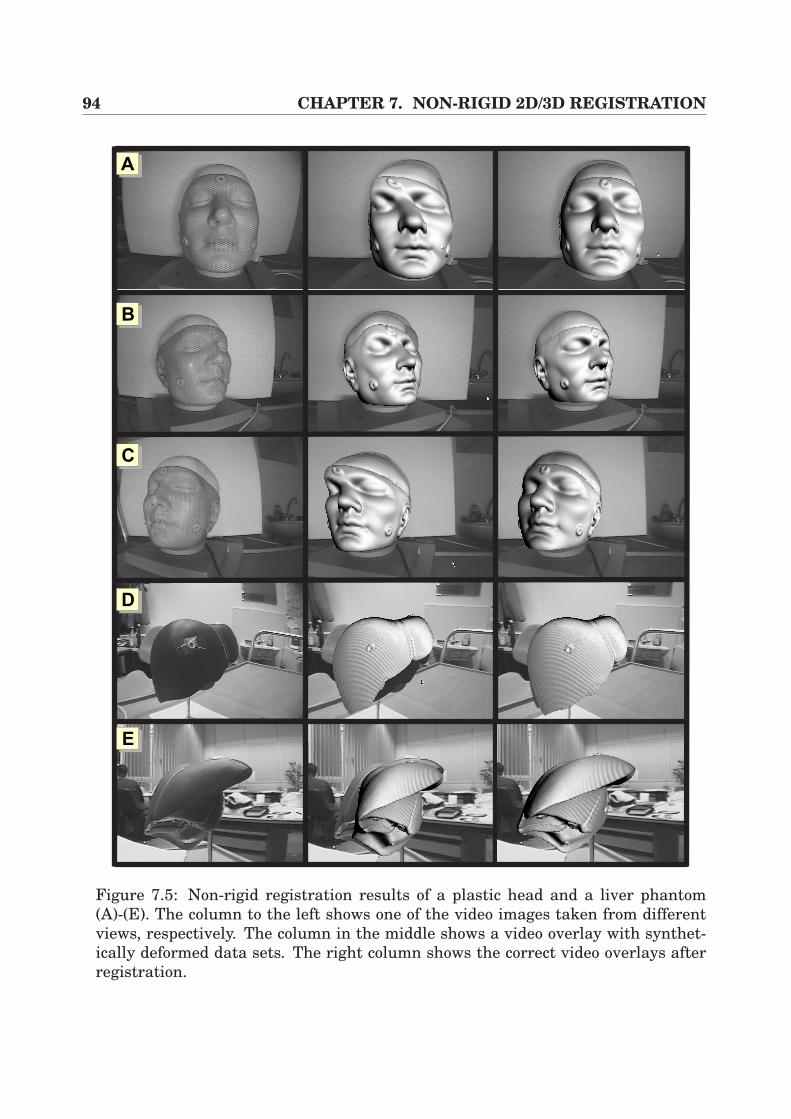
94 CHAPTER 7. NON-RIGID 2D/3D REGISTRATION
AA
AB
AC
AD
AE
Figure 7.5: Non-rigid registration results of a plastic head and a liver phantom(A)-(E). The column to the left shows one of the video images taken from differentviews, respectively. The column in the middle shows a video overlay with synthet-ically deformed data sets. The right column shows the correct video overlays afterregistration.
Part III
Medical Applications

96
Chapter 8
Intra-operative Liver InterventionAssistance
Minimally invasive liver interventions require a lot of experience due to the limitedaccess to the field of operation. In particular, the correct placement of the trocarand the navigation within the patient’s body are hampered, as already discussedin Chapter 1. In this chapter, an intra-operative augmented reality system (IARS)is presented which directly projects pre-operatively planned information and struc-tures extracted from CT data onto the real laparoscopic video images. In particular,pre-operative planning results of a liver planning tool are applied for liver surgery.This software takes into account the individual anatomy of the intra-hepatic vesselsand determines the vascular territories, which implies intelligent segmentation ofthe liver parenchyma1, of the intra-hepatic vessels and of liver lesions. The gen-erated information is then directly projected onto the surgeon’s view in order toperform the planning of incision points for Veress needle and trocars.
This chapter is divided into the following sections. It starts with a motivation,introducing the topic and placing it into its context (Section 8.1). In order to un-derstand the medical background, the anatomy of the liver and its physiology arepresented in Section 8.2. Afterwards, a very brief overview of the fundamental stepsof our pre-operative planning software HEPAVISION [15] is given, which producesliver planning information according to the newest research in image segmenta-tion and processing. In Section 8.4 the intra-operative setup for augmentation isdescribed, including calibration, registration, visualization and hardware setup. Fi-nally, the evaluation results of the application are presented in Section 8.5 and aconclusion is contained in Section 8.6.
1The essential and distinctive tissue of an organ.
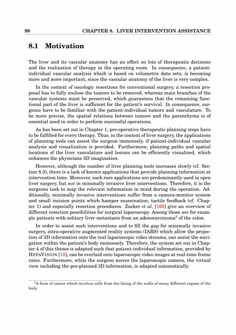
98 CHAPTER 8. LIVER INTERVENTION ASSISTANCE
8.1 Motivation
The liver and its vascular anatomy has an effect on lots of therapeutic decisionsand the realization of therapy in the operating room. In consequence, a patient-individual vascular analysis which is based on volumetric data sets, is becomingmore and more important, since the vascular anatomy of the liver is very complex.
In the context of oncologic resections for conventional surgery, a resection pro-posal has to fully enclose the tumors to be removed, whereas main branches of thevascular systems must be preserved, which guarantees that the remaining func-tional part of the liver is sufficient for the patient’s survival. In consequence, sur-geons have to be familiar with the patient-individual tumors and vasculature. Tobe more precise, the spatial relations between tumors and the parenchyma is ofessential need in order to perform successful operations.
As has been set out in Chapter 1, pre-operative therapeutic planning steps haveto be fulfilled for every therapy. Thus, in the context of liver surgery, the applicationsof planning tools can assist the surgeon immensely, if patient-individual vascularanalysis and visualization is provided. Furthermore, planning paths and spatiallocations of the liver vasculature and lesions can be efficiently visualized, whichenhances the physicians 3D imagination.
However, although the number of liver planning tools increases slowly (cf. Sec-tion 8.3), there is a lack of known applications that provide planning information atintervention time. Moreover, such rare applications are predominantly used in openliver surgery, but not in minimally invasive liver interventions. Therefore, it is thesurgeons task to map the relevant information in mind during the operation. Ad-ditionally, minimally invasive interventions suffer from a camera-monitor systemand small incision points which hamper examination, tactile feedback (cf. Chap-ter 1) and especially resection procedures. Zucker et al. [160] give an overview ofdifferent resection possibilities for surgical laparoscopy. Among those are for exam-ple patients with solitary liver metastasis from an adenocarcinoma2 of the colon.
In order to assist such interventions and to fill the gap for minimally invasivesurgery, intra-operative augmented reality systems (IARS) which allow the projec-tion of 3D information onto the real laparoscopic video streams, can assist the navi-gation within the patient’s body immensely. Therefore, the system set out in Chap-ter 4 of this theses is adapted such that patient-individual information, provided byHEPAVISION [15], can be overlaid onto laparoscopic video images at real-time framerates. Furthermore, while the surgeon moves the laparoscopic camera, the virtualview including the pre-planned 3D information, is adapted automatically.
2A form of cancer which involves cells from the lining of the walls of many different organs of thebody.
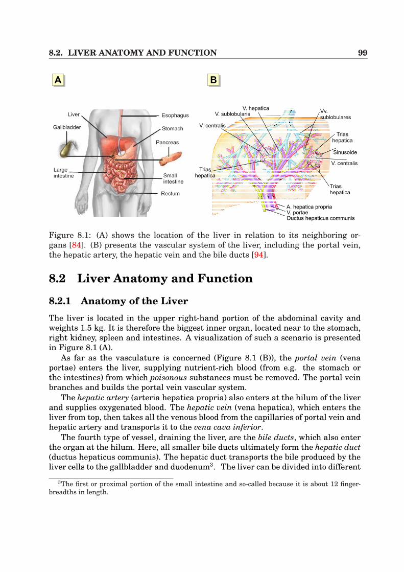
8.2. LIVER ANATOMY AND FUNCTION 99
AA AB
V. portaeA. hepatica propria
Ductus hepaticus communis
Triashepatica
V. centralis
Sinusoide
Triashepatica
Vv.sublobulares
V. hepaticaV. sublobularis
V. centralis
Triashepatica
Esophagus
Stomach
Pancreas
Smallintestine
Rectum
Liver
Gallbladder
Largeintestine
Figure 8.1: (A) shows the location of the liver in relation to its neighboring or-gans [84]. (B) presents the vascular system of the liver, including the portal vein,the hepatic artery, the hepatic vein and the bile ducts [94].
8.2 Liver Anatomy and Function
8.2.1 Anatomy of the LiverThe liver is located in the upper right-hand portion of the abdominal cavity andweights 1.5 kg. It is therefore the biggest inner organ, located near to the stomach,right kidney, spleen and intestines. A visualization of such a scenario is presentedin Figure 8.1 (A).
As far as the vasculature is concerned (Figure 8.1 (B)), the portal vein (venaportae) enters the liver, supplying nutrient-rich blood (from e.g. the stomach orthe intestines) from which poisonous substances must be removed. The portal veinbranches and builds the portal vein vascular system.
The hepatic artery (arteria hepatica propria) also enters at the hilum of the liverand supplies oxygenated blood. The hepatic vein (vena hepatica), which enters theliver from top, then takes all the venous blood from the capillaries of portal vein andhepatic artery and transports it to the vena cava inferior.
The fourth type of vessel, draining the liver, are the bile ducts, which also enterthe organ at the hilum. Here, all smaller bile ducts ultimately form the hepatic duct(ductus hepaticus communis). The hepatic duct transports the bile produced by theliver cells to the gallbladder and duodenum3. The liver can be divided into different
3The first or proximal portion of the small intestine and so-called because it is about 12 finger-breadths in length.
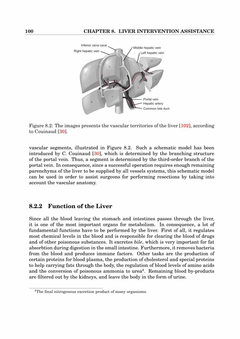
100 CHAPTER 8. LIVER INTERVENTION ASSISTANCE
Portal vein
Hepatic artery
Common bile duct
Left hepatic vein
Middle hepatic veinInferior vena cava
Right hepatic vein
Figure 8.2: The images presents the vascular territories of the liver [102], accordingto Couinaud [30].
vascular segments, illustrated in Figure 8.2. Such a schematic model has beenintroduced by C. Couinaud [30], which is determined by the branching structureof the portal vein. Thus, a segment is determined by the third-order branch of theportal vein. In consequence, since a successful operation requires enough remainingparenchyma of the liver to be supplied by all vessels systems, this schematic modelcan be used in order to assist surgeons for performing resections by taking intoaccount the vascular anatomy.
8.2.2 Function of the Liver
Since all the blood leaving the stomach and intestines passes through the liver,it is one of the most important organs for metabolism. In consequence, a lot offundamental functions have to be performed by the liver. First of all, it regulatesmost chemical levels in the blood and is responsible for clearing the blood of drugsand of other poisonous substances. It excretes bile, which is very important for fatabsorbtion during digestion in the small intestine. Furthermore, it removes bacteriafrom the blood and produces immune factors. Other tasks are the production ofcertain proteins for blood plasma, the production of cholesterol and special proteinsto help carrying fats through the body, the regulation of blood levels of amino acidsand the conversion of poisonous ammonia to urea4. Remaining blood by-productsare filtered out by the kidneys, and leave the body in the form of urine.
4The final nitrogenous excretion product of many organisms.
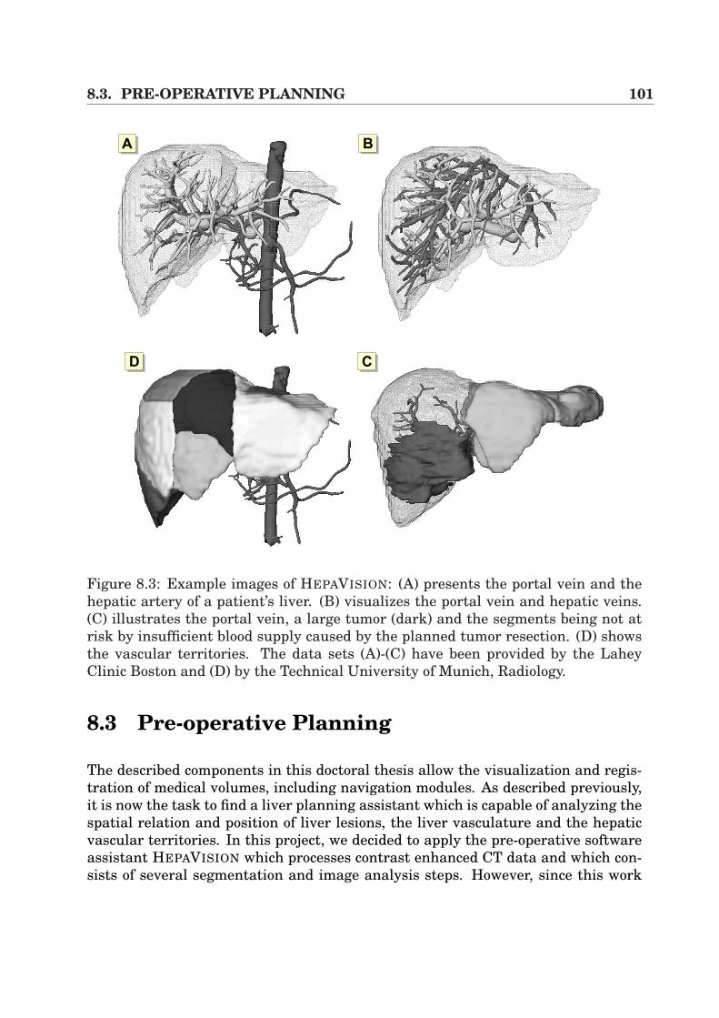
8.3. PRE-OPERATIVE PLANNING 101
AA AB
ACAD
Figure 8.3: Example images of HEPAVISION: (A) presents the portal vein and thehepatic artery of a patient’s liver. (B) visualizes the portal vein and hepatic veins.(C) illustrates the portal vein, a large tumor (dark) and the segments being not atrisk by insufficient blood supply caused by the planned tumor resection. (D) showsthe vascular territories. The data sets (A)-(C) have been provided by the LaheyClinic Boston and (D) by the Technical University of Munich, Radiology.
8.3 Pre-operative Planning
The described components in this doctoral thesis allow the visualization and regis-tration of medical volumes, including navigation modules. As described previously,it is now the task to find a liver planning assistant which is capable of analyzing thespatial relation and position of liver lesions, the liver vasculature and the hepaticvascular territories. In this project, we decided to apply the pre-operative softwareassistant HEPAVISION which processes contrast enhanced CT data and which con-sists of several segmentation and image analysis steps. However, since this work
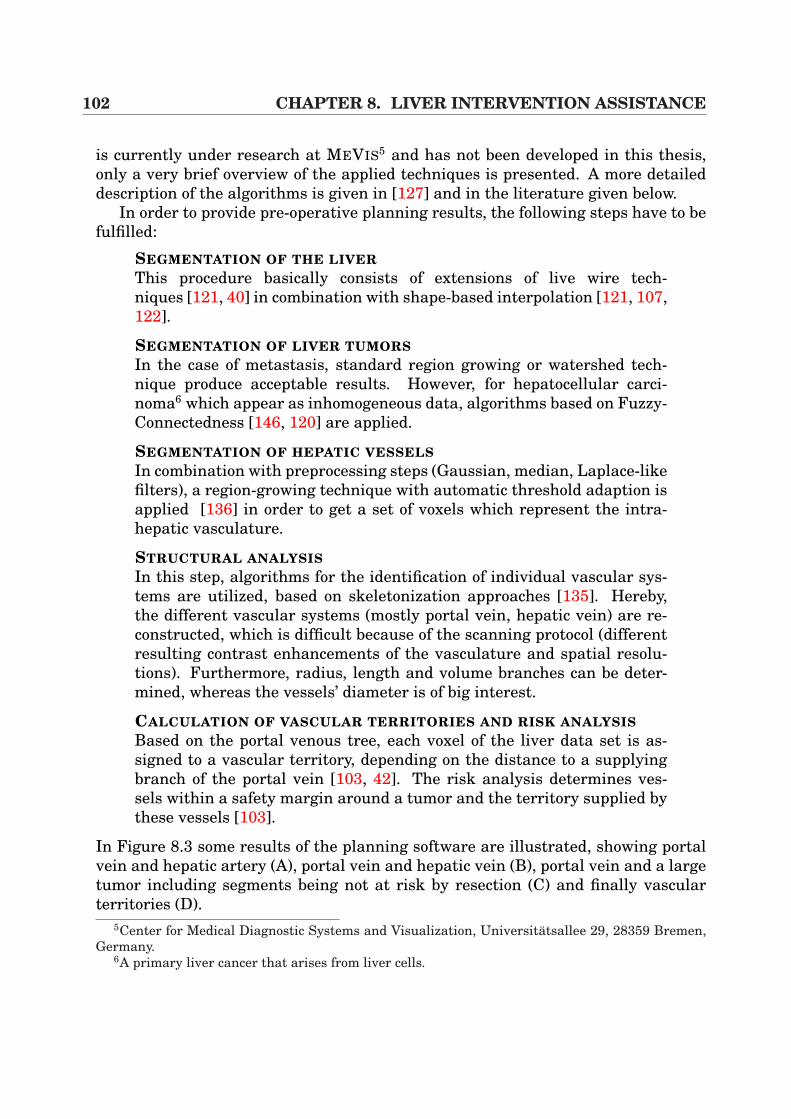
102 CHAPTER 8. LIVER INTERVENTION ASSISTANCE
is currently under research at MEVIS5 and has not been developed in this thesis,only a very brief overview of the applied techniques is presented. A more detaileddescription of the algorithms is given in [127] and in the literature given below.
In order to provide pre-operative planning results, the following steps have to befulfilled:
SEGMENTATION OF THE LIVERThis procedure basically consists of extensions of live wire tech-niques [121, 40] in combination with shape-based interpolation [121, 107,122].
SEGMENTATION OF LIVER TUMORSIn the case of metastasis, standard region growing or watershed tech-nique produce acceptable results. However, for hepatocellular carci-noma6 which appear as inhomogeneous data, algorithms based on Fuzzy-Connectedness [146, 120] are applied.
SEGMENTATION OF HEPATIC VESSELSIn combination with preprocessing steps (Gaussian, median, Laplace-likefilters), a region-growing technique with automatic threshold adaption isapplied [136] in order to get a set of voxels which represent the intra-hepatic vasculature.
STRUCTURAL ANALYSISIn this step, algorithms for the identification of individual vascular sys-tems are utilized, based on skeletonization approaches [135]. Hereby,the different vascular systems (mostly portal vein, hepatic vein) are re-constructed, which is difficult because of the scanning protocol (differentresulting contrast enhancements of the vasculature and spatial resolu-tions). Furthermore, radius, length and volume branches can be deter-mined, whereas the vessels’ diameter is of big interest.
CALCULATION OF VASCULAR TERRITORIES AND RISK ANALYSISBased on the portal venous tree, each voxel of the liver data set is as-signed to a vascular territory, depending on the distance to a supplyingbranch of the portal vein [103, 42]. The risk analysis determines ves-sels within a safety margin around a tumor and the territory supplied bythese vessels [103].
In Figure 8.3 some results of the planning software are illustrated, showing portalvein and hepatic artery (A), portal vein and hepatic vein (B), portal vein and a largetumor including segments being not at risk by resection (C) and finally vascularterritories (D).
5Center for Medical Diagnostic Systems and Visualization, Universitatsallee 29, 28359 Bremen,Germany.
6A primary liver cancer that arises from liver cells.
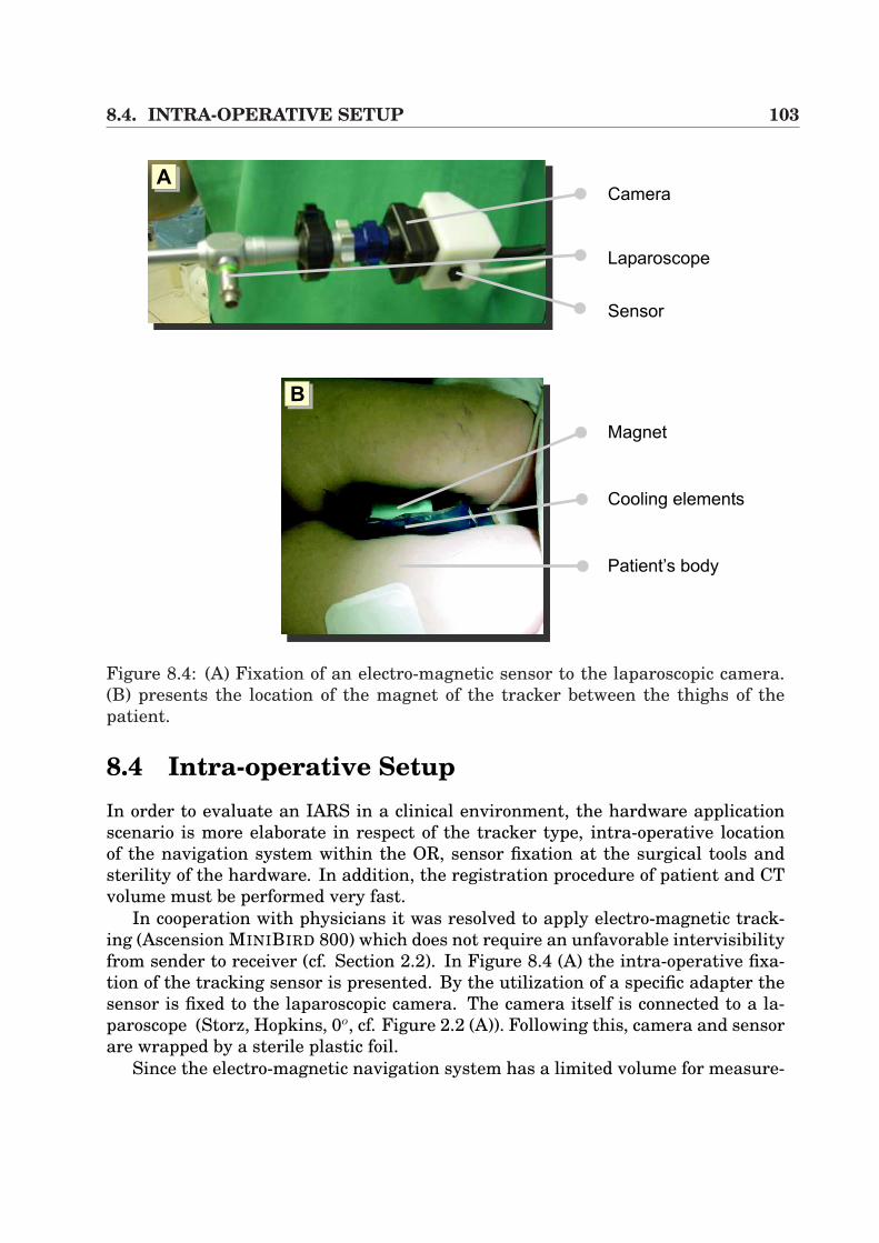
8.4. INTRA-OPERATIVE SETUP 103
Camera
Laparoscope
Sensor
Magnet
Patient’s body
Cooling elements
AA
AB
Figure 8.4: (A) Fixation of an electro-magnetic sensor to the laparoscopic camera.(B) presents the location of the magnet of the tracker between the thighs of thepatient.
8.4 Intra-operative SetupIn order to evaluate an IARS in a clinical environment, the hardware applicationscenario is more elaborate in respect of the tracker type, intra-operative locationof the navigation system within the OR, sensor fixation at the surgical tools andsterility of the hardware. In addition, the registration procedure of patient and CTvolume must be performed very fast.
In cooperation with physicians it was resolved to apply electro-magnetic track-ing (Ascension MINIBIRD 800) which does not require an unfavorable intervisibilityfrom sender to receiver (cf. Section 2.2). In Figure 8.4 (A) the intra-operative fixa-tion of the tracking sensor is presented. By the utilization of a specific adapter thesensor is fixed to the laparoscopic camera. The camera itself is connected to a la-paroscope (Storz, Hopkins, 0o, cf. Figure 2.2 (A)). Following this, camera and sensorare wrapped by a sterile plastic foil.
Since the electro-magnetic navigation system has a limited volume for measure-
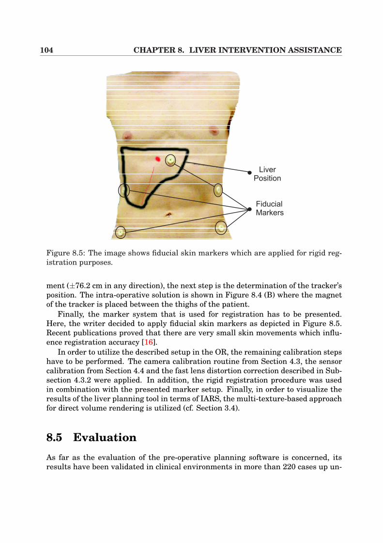
104 CHAPTER 8. LIVER INTERVENTION ASSISTANCE
Liver
Position
Fiducial
Markers
Figure 8.5: The image shows fiducial skin markers which are applied for rigid reg-istration purposes.
ment (±76.2 cm in any direction), the next step is the determination of the tracker’sposition. The intra-operative solution is shown in Figure 8.4 (B) where the magnetof the tracker is placed between the thighs of the patient.
Finally, the marker system that is used for registration has to be presented.Here, the writer decided to apply fiducial skin markers as depicted in Figure 8.5.Recent publications proved that there are very small skin movements which influ-ence registration accuracy [16].
In order to utilize the described setup in the OR, the remaining calibration stepshave to be performed. The camera calibration routine from Section 4.3, the sensorcalibration from Section 4.4 and the fast lens distortion correction described in Sub-section 4.3.2 were applied. In addition, the rigid registration procedure was usedin combination with the presented marker setup. Finally, in order to visualize theresults of the liver planning tool in terms of IARS, the multi-texture-based approachfor direct volume rendering is utilized (cf. Section 3.4).
8.5 EvaluationAs far as the evaluation of the pre-operative planning software is concerned, itsresults have been validated in clinical environments in more than 220 cases up un-
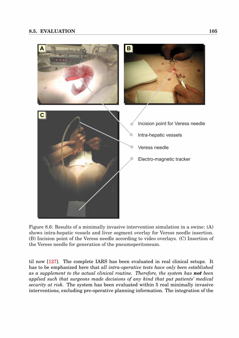
8.5. EVALUATION 105
Intra-hepatic vessels
Incision point for Veress needle
Veress needle
Electro-magnetic tracker
AA AB
AC
Figure 8.6: Results of a minimally invasive intervention simulation in a swine: (A)shows intra-hepatic vessels and liver segment overlay for Veress needle insertion.(B) Incision point of the Veress needle according to video overlays. (C) Insertion ofthe Veress needle for generation of the pneumoperitoneum.
til now [127]. The complete IARS has been evaluated in real clinical setups. Ithas to be emphasized here that all intra-operative tests have only been establishedas a supplement to the actual clinical routine. Therefore, the system has not beenapplied such that surgeons made decisions of any kind that put patients’ medicalsecurity at risk. The system has been evaluated within 5 real minimally invasiveinterventions, excluding pre-operative planning information. The integration of the
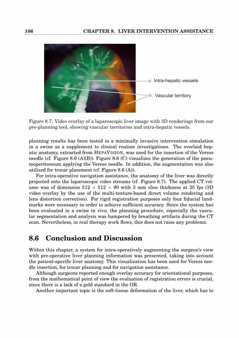
106 CHAPTER 8. LIVER INTERVENTION ASSISTANCE
Vascular territory
Intra-hepatic vessels
Figure 8.7: Video overlay of a laparoscopic liver image with 3D renderings from ourpre-planning tool, showing vascular territories and intra-hepatic vessels.
planning results has been tested in a minimally invasive intervention simulationin a swine as a supplement to clinical routine investigations. The overlaid hep-atic anatomy, extracted from HEPAVISION, was used for the insertion of the Veressneedle (cf. Figure 8.6 (A)(B)). Figure 8.6 (C) visualizes the generation of the pneu-moperitoneum applying the Veress needle. In addition, the augmentation was alsoutilized for trocar placement (cf. Figure 8.6 (A)).
For intra-operative navigation assistance, the anatomy of the liver was directlyprojected onto the laparoscopic video streams (cf. Figure 8.7). The applied CT vol-ume was of dimension 512 × 512 × 90 with 3 mm slice thickness at 25 fps (3Dvideo overlay by the use of the multi-texture-based direct volume rendering andlens distortion correction). For rigid registration purposes only four fiducial land-marks were necessary in order to achieve sufficient accuracy. Since the system hasbeen evaluated in a swine in vivo, the planning procedure, especially the vascu-lar segmentation and analysis was hampered by breathing artifacts during the CTscan. Nevertheless, in real therapy work flows, this does not raise any problems.
8.6 Conclusion and DiscussionWithin this chapter, a system for intra-operatively augmenting the surgeon’s viewwith pre-operative liver planning information was presented, taking into accountthe patient-specific liver anatomy. This visualization has been used for Veress nee-dle insertion, for trocar planning and for navigation assistance.
Although surgeons reported enough overlay accuracy for orientational purposes,from the mathematical point of view the evaluation of registration errors is crucial,since there is a lack of a gold standard in the OR.
Another important topic is the soft-tissue deformation of the liver, which has to

8.6. CONCLUSION AND DISCUSSION 107
be considered in order to make the application suitable for exact tumor resectionguidance. Vetter et al. [147] suggest to use 3D ultrasound in order to register CTand patient using vessel bifurcations7. In combination with our interactive volumedeformation systems, presented in Chapter 6, fast 3D/3D registration could becomepossible in the near future. This allows the accurate application of navigated radio-frequency therapy (RFT) or percutaneous ethanol injection therapy (PEIT) for tu-mor treatments. This topic will be discussed in Chapter 10.
7Split into two parts.

108 CHAPTER 8. LIVER INTERVENTION ASSISTANCE
Chapter 9
Repositioning of Bone FractureSegments
In the previous sections, standard CT or MR tomography was the chosen imagingmodality for the above mentioned applications. However, there are a few medical ap-plications that use alternative imaging like C-arm scanners. These systems providea very flexible imaging technique, because of their mobility within the operatingroom and their reduced radiation level.
One of the increasing medical applications of C-arms are used in osseous surgery,where 2D or 3D images can be used to assist the surgeon intra-operatively duringnavigation. Furthermore, they are also applied for intervention controlling pur-poses. Standard examples are total hip replacements or knee interventions (recallSubsection 2.2.5).
The developed algorithms and applications in this work provide basic researchfor an intra-operative surgery assistance. In this chapter, a framework that hasbeen developed in order to assist the pre-operative planning process of bone fracturefixation is presented. In this context, the aims is to enhance the surgeon’s realityby a pre-operative planning tool which allows the display and repositioning of bonefractures in 3D.
9.1 Introduction and BackgroundNowadays, bone fractures can easily be treated by surgeons using standard x-raytechniques in order to get an overview of the patient individual bone anatomy. How-ever, this treatment is only valid in the case of reduced fracture complexity. In Fig-ure 9.1 (A), different types of bone fractures are presented. According to image (B)it becomes quite evident that standard treatments have to be extended in order tohandle complex fractures. By the use of surgery simulation techniques in a purelyvirtual environment using mobile C-arm modality, surgeons can apply 3D visualiza-tion techniques in order to simulate the bone fixation procedure, which enhances the
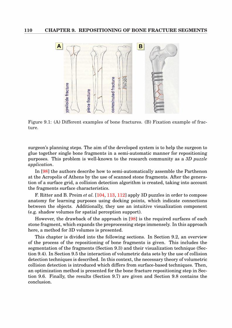
110 CHAPTER 9. REPOSITIONING OF BONE FRACTURE SEGMENTS
AA AB
Figure 9.1: (A) Different examples of bone fractures. (B) Fixation example of frac-ture.
surgeon’s planning steps. The aim of the developed system is to help the surgeon toglue together single bone fragments in a semi-automatic manner for repositioningpurposes. This problem is well-known to the research community as a 3D puzzleapplication.
In [98] the authors describe how to semi-automatically assemble the Parthenonat the Acropolis of Athens by the use of scanned stone fragments. After the genera-tion of a surface grid, a collision detection algorithm is created, taking into accountthe fragments surface characteristics.
F. Ritter and B. Preim et al. [104, 113, 112] apply 3D puzzles in order to composeanatomy for learning purposes using docking points, which indicate connectionsbetween the objects. Additionally, they use an intuitive visualization component(e.g. shadow volumes for spatial perception support).
However, the drawback of the approach in [98] is the required surfaces of eachstone fragment, which expands the preprocessing steps immensely. In this approachhere, a method for 3D volumes is presented.
This chapter is divided into the following sections. In Section 9.2, an overviewof the process of the repositioning of bone fragments is given. This includes thesegmentation of the fragments (Section 9.3) and their visualization technique (Sec-tion 9.4). In Section 9.5 the interaction of volumetric data sets by the use of collisiondetection techniques is described. In this context, the necessary theory of volumetriccollision detection is introduced which differs from surface-based techniques. Then,an optimization method is presented for the bone fracture repositioning step in Sec-tion 9.6. Finally, the results (Section 9.7) are given and Section 9.8 contains theconclusion.
9.2. ALGORITHM OVERVIEW 111
9.2 Algorithm OverviewThe approach to reposition bone fracture segments can be mainly divided into fourparts:
Segmentation This preprocessing step is the basis for manual repositioning bythe physicist. It has to be performed in order to classify the patient-individualbone fragments within the volumetric C-arm data set.
Visualization Here a very flexible framework has to be used, since the ability tomove and pick single volumes is required in order to align bone fragments.
Collision detection During semi-automatic alignment, the surgeon needs naviga-tional feedback in order to avoid bone overlaps and to achieve correct reposi-tioning results. Thus, efficient, robust and fast algorithms for volume collisiondetection have to be implemented.
Optimization of bone positions The last stage attempts to align two bone frag-ments by the optimization of a metric, based on fragment specific principleaxes and collision volume.
In the following, each step of this procedure will be explained more detailed.
9.3 SegmentationIn this application, the manual repositioning requires the ability to independentlymove several bone fragments. Thus, collision detection algorithms are needed inorder to perform correct alignment. However, fast and intuitive segmentation isrequired in order to extract bone voxel information from soft-tissue within the vol-umetric data set. In the context of CT volumes, this segmentation step can be per-formed using simple threshold-based techniques. The well-known Hounsfield scalesimplifies this procedures. In the case of C-arm modalities, we expand this semi-automatic segmentation by the introduction of region-growing algorithms. This al-lows a separation of the bone structure from surrounding tissue in a simple way.However, the results obtained by this semi-automatic approach must again be con-trolled and corrected manually.
9.4 VisualizationNowadays, there are a wide variety of efficient algorithms for direct volume ren-dering. Those approaches range from pure software solutions to the developmentof special purpose hardware [101, 87], and to methods which exploit the steadilyevolving features of general purpose graphics hardware [19, 17, 152, 86, 109]. This
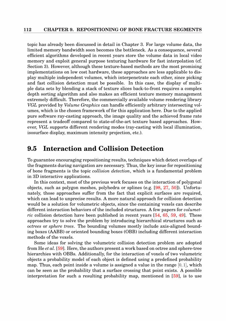
112 CHAPTER 9. REPOSITIONING OF BONE FRACTURE SEGMENTS
topic has already been discussed in detail in Chapter 3. For large volume data, thelimited memory bandwidth soon becomes the bottleneck. As a consequence, severalefficient algorithms developed in recent years store the volume data in local videomemory and exploit general purpose texturing hardware for fast interpolation (cf.Section 3). However, although these texture-based methods are the most promisingimplementations on low cost hardware, these approaches are less applicable to dis-play multiple independent volumes, which interpenetrate each other, since pickingand fast collision detection must be possible. In this case, the display of multi-ple data sets by blending a stack of texture slices back-to-front requires a complexdepth sorting algorithm and also makes an efficient texture memory managementextremely difficult. Therefore, the commercially available volume rendering libraryVGL provided by Volume Graphics can handle efficiently arbitrary intersecting vol-umes, which is the chosen framework of for this application here. Due to the appliedpure software ray-casting approach, the image quality and the achieved frame raterepresent a tradeoff compared to state-of-the-art texture based approaches. How-ever, VGL supports different rendering modes (ray-casting with local illumination,isosurface display, maximum intensity projection, etc.).
9.5 Interaction and Collision DetectionTo guarantee encouraging repositioning results, techniques which detect overlaps ofthe fragments during navigation are necessary. Thus, the key issue for repositioningof bone fragments is the topic collision detection, which is a fundamental problemin 3D interactive applications.
In this context, most of the previous work focuses on the interaction of polygonalobjects, such as polygon meshes, polyhedra or splines (e.g. [98, 27, 50]). Unfortu-nately, those approaches suffer from the fact that explicit surfaces are required,which can lead to unprecise results. A more natural approach for collision detectionwould be a solution for volumetric objects, since the containing voxels can describedifferent interaction behaviors of the included structures. A few papers for volumet-ric collision detection have been published in recent years [54, 65, 59, 49]. Theseapproaches try to solve the problem by introducing hierarchical structures such asoctrees or sphere trees. The bounding volumes mostly include axis-aligned bound-ing boxes (AABB) or oriented bounding boxes (OBB) including different interactionmethods of the voxels.
Some ideas for solving the volumetric collision detection problem are adoptedfrom He et al. [59]. Here, the authors present a work based on octree and sphere-treehierarchies with OBBs. Additionally, for the interaction of voxels of two volumetricobjects a probability model of each object is defined using a predefined probabilitymap. Thus, each point inside a volume is assigned a value in the range [0, 1], whichcan be seen as the probability that a surface crossing that point exists. A possibleinterpretation for such a resulting probability map, mentioned in [59], is to use
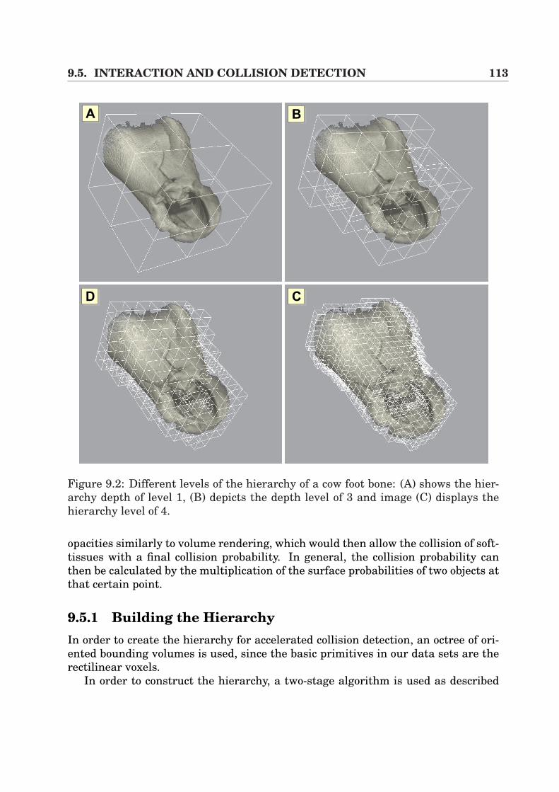
9.5. INTERACTION AND COLLISION DETECTION 113
AA AB
ACAD
Figure 9.2: Different levels of the hierarchy of a cow foot bone: (A) shows the hier-archy depth of level 1, (B) depicts the depth level of 3 and image (C) displays thehierarchy level of 4.
opacities similarly to volume rendering, which would then allow the collision of soft-tissues with a final collision probability. In general, the collision probability canthen be calculated by the multiplication of the surface probabilities of two objects atthat certain point.
9.5.1 Building the HierarchyIn order to create the hierarchy for accelerated collision detection, an octree of ori-ented bounding volumes is used, since the basic primitives in our data sets are therectilinear voxels.
In order to construct the hierarchy, a two-stage algorithm is used as described
114 CHAPTER 9. REPOSITIONING OF BONE FRACTURE SEGMENTS
B
A
B
Ar
a1 1
a2 2
rB
b2 2
1 1b
L
T
LT
AA
B
! "#$ %&$' () (*(+ $ *(,(- * ($ %$./( () /0(* $& () 1$2* $0($ () ,2*+,03 ,4*$ ($ /$'%( () ,3 $& () 0(5,4*6 7& () 3*(,0/ 1(80 () 1$2 /0(* ,*
%$./(3 $0($ () ,2* * ,( (),0 () *' $& () ,3+ ()0 () 0(5,4* 9,03 ()1$2* ,* 844: , 3*.$0(6 #)* * *)$80 0 ; 0 6 6< ,**' 8 , 50 (8$ =>>*+ ,03 + 8() %4,/3 4,(5 ($ 1- $(,($0? ,03 (,0*4,($0 @ 6 #) ),4&A3'0*$0* 9$ B,3C: $& ,03 , DE ,03 FE + 8)G H IJ J K6 < 844 30$( () ,2* $& ,03 ,* () 0( 5/($* E ,03 E + &$ G H IJ J K6#)* 844 1 &3 ($ ,* () L 1$2 ,2*6 M$( (),( & 8 * () 1$2 ,2* $& ,* ,1,**+ ()0 () () /$4'0* $& ? , () *,' ,* () () E 5/($*6#) /0(* $& ,/) 1$2 %$./(* $0($ () '3%$0( $& (* 0(5,46 >- %$./(0 ()1$2 ,3 $0($ () ,2*+ ,03 *''0 () 40() $& () ',*+ 8 $1(,0 () ,3* $&() 0(5,46 7& () ,2* * %,,444 ($ () 0( 5/($ + ()0 () ,3* $& 1$2 C* 0(5,4*NO H PE QDE E R Q
S *'4, 2%**$0 * *3 &$ NT 6#) %4,/'0( $& () ,2* * '',(,4+ *$ 8 ,**' ( %,*** ()$) () /0( $&U
Figure 9.3: L is a separating axis of OBBs A and B because A and B become disjointintervals under projection onto L.
in [59]. Firstly, the algorithm starts bottom-up from the leafs and merges the eightneighboring nodes. Since this approach also includes nodes that do not containany relevant information (e.g. empty voxels), a second step is added to reduce theoverhead of collision detection by pruning the tree top-down.
Thus, each node N i in the hierarchy is assigned a value interval [N iρmin
, N iρmax
],that represents the minimum and maximum collision probabilities of that node. Inaddition, the user specifies a solid threshold τmax and an empty threshold τmin, whichshorten the tree. In the second stage, which is recursively defined, the algorithmstarts at the root node whereas breadth-first traversal is used. By taking N i as thecurrent node, the following decisions have to be made [59]:
• If N iρmax
< τmin, delete both N i and all its childs.
• If N iρmin
> τmax, delete all the childs of N i.
• For a direct child N i1 of N i, if N i
1 has only one child N i2, then delete N i
1 and makeN i
2 to be the child of N i.
Using this second stage of the algorithm reduces the tree to those nodes, that con-tain only voxels with τmin < ρ < τmax. Changing the values of τmin or τmax by the userincreases or decreases the complexity of the hierarchy. Figure 9.2 shows the resultsof a cow foot bone, which presents different levels of the hierarchy.
9.5.2 Collision DetectionThe previous section described how to realize a reduced hierarchy of the volumetricobjects. Efficient algorithms now have to be used for interference detection of the
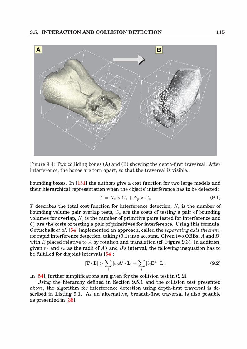
9.5. INTERACTION AND COLLISION DETECTION 115
AA AB
Figure 9.4: Two colliding bones (A) and (B) showing the depth-first traversal. Afterinterference, the bones are torn apart, so that the traversal is visible.
bounding boxes. In [151] the authors give a cost function for two large models andtheir hierarchical representation when the objects’ interference has to be detected:
T = Nv × Cv + Np × Cp (9.1)
T describes the total cost function for interference detection, Nv is the number ofbounding volume pair overlap tests, Cv are the costs of testing a pair of boundingvolumes for overlap, Np is the number of primitive pairs tested for interference andCp are the costs of testing a pair of primitives for interference. Using this formula,Gottschalk et al. [54] implemented an approach, called the separating axis theorem,for rapid interference detection, taking (9.1) into account. Given two OBBs, A and B,with B placed relative to A by rotation and translation (cf. Figure 9.3). In addition,given rA and rB as the radii of A’s and B’s interval, the following inequation has tobe fulfilled for disjoint intervals [54]:
|T · L| >∑
i
|aiAi · L|+
∑i
|biBi · L|. (9.2)
In [54], further simplifications are given for the collision test in (9.2).Using the hierarchy defined in Section 9.5.1 and the collision test presented
above, the algorithm for interference detection using depth-first traversal is de-scribed in Listing 9.1. As an alternative, breadth-first traversal is also possibleas presented in [38].
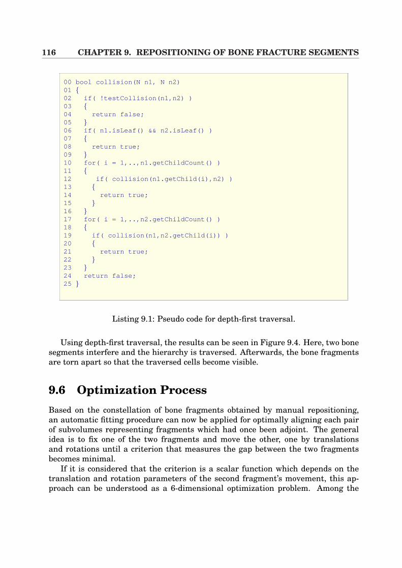
116 CHAPTER 9. REPOSITIONING OF BONE FRACTURE SEGMENTS
00 bool collision(N n1, N n2)01 02 if( !testCollision(n1,n2) )03 04 return false;05 06 if( n1.isLeaf() && n2.isLeaf() )07 08 return true;09 10 for( i = 1,..,n1.getChildCount() )11 12 if( collision(n1.getChild(i),n2) )13 14 return true;15 16 17 for( i = 1,..,n2.getChildCount() )18 19 if( collision(n1,n2.getChild(i)) )20 21 return true;22 23 24 return false;25
Listing 9.1: Pseudo code for depth-first traversal.
Using depth-first traversal, the results can be seen in Figure 9.4. Here, two bonesegments interfere and the hierarchy is traversed. Afterwards, the bone fragmentsare torn apart so that the traversed cells become visible.
9.6 Optimization ProcessBased on the constellation of bone fragments obtained by manual repositioning,an automatic fitting procedure can now be applied for optimally aligning each pairof subvolumes representing fragments which had once been adjoint. The generalidea is to fix one of the two fragments and move the other, one by translationsand rotations until a criterion that measures the gap between the two fragmentsbecomes minimal.
If it is considered that the criterion is a scalar function which depends on thetranslation and rotation parameters of the second fragment’s movement, this ap-proach can be understood as a 6-dimensional optimization problem. Among the
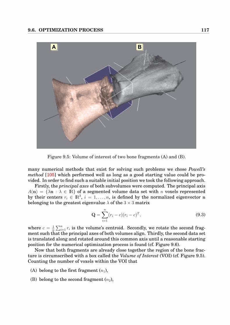
9.6. OPTIMIZATION PROCESS 117
AA AB
Figure 9.5: Volume of interest of two bone fragments (A) and (B).
many numerical methods that exist for solving such problems we chose Powell’smethod [105] which performed well as long as a good starting value could be pro-vided. In order to find such a suitable initial position we took the following approach.
Firstly, the principal axes of both subvolumes were computed. The principal axisA(n) = λn : λ ∈ IR of a segmented volume data set with n voxels representedby their centers ri ∈ IR3, i = 1, . . . , n, is defined by the normalized eigenvector nbelonging to the greatest eigenvalue λ of the 3× 3 matrix
Q =n∑
i=1
(ri − c)(ri − c)T , (9.3)
where c = 1n
∑ni=1 ri is the volume’s centroid. Secondly, we rotate the second frag-
ment such that the principal axes of both volumes align. Thirdly, the second data setis translated along and rotated around this common axis until a reasonable startingposition for the numerical optimization process is found (cf. Figure 9.6).
Now that both fragments are already close together the region of the bone frac-ture is circumscribed with a box called the Volume of Interest (VOI) (cf. Figure 9.5).Counting the number of voxels within the VOI that
(A) belong to the first fragment (n1),
(B) belong to the second fragment (n2),
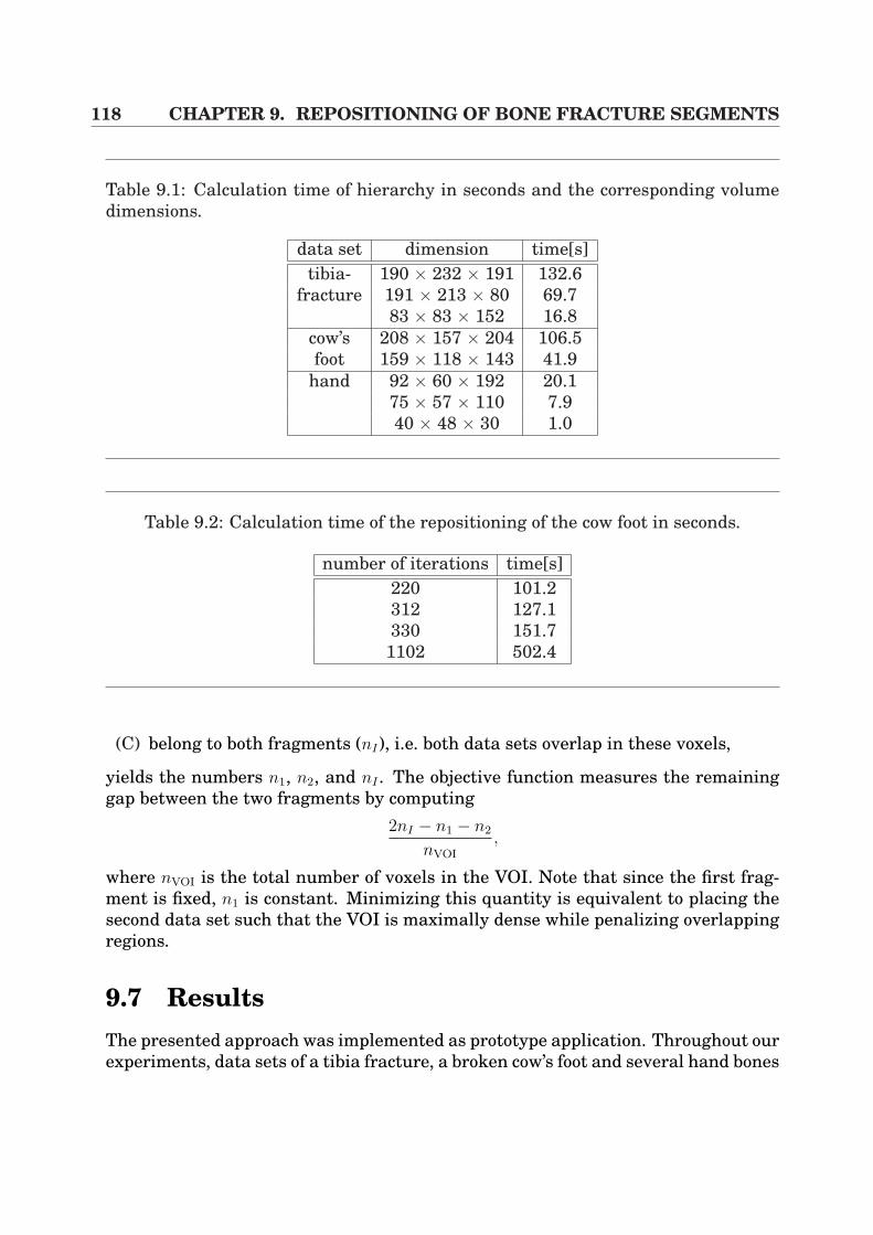
118 CHAPTER 9. REPOSITIONING OF BONE FRACTURE SEGMENTS
Table 9.1: Calculation time of hierarchy in seconds and the corresponding volumedimensions.
data set dimension time[s]tibia- 190 × 232 × 191 132.6
fracture 191 × 213 × 80 69.783 × 83 × 152 16.8
cow’s 208 × 157 × 204 106.5foot 159 × 118 × 143 41.9
hand 92 × 60 × 192 20.175 × 57 × 110 7.940 × 48 × 30 1.0
Table 9.2: Calculation time of the repositioning of the cow foot in seconds.
number of iterations time[s]220 101.2312 127.1330 151.71102 502.4
(C) belong to both fragments (nI), i.e. both data sets overlap in these voxels,
yields the numbers n1, n2, and nI . The objective function measures the remaininggap between the two fragments by computing
2nI − n1 − n2
nVOI
,
where nVOI is the total number of voxels in the VOI. Note that since the first frag-ment is fixed, n1 is constant. Minimizing this quantity is equivalent to placing thesecond data set such that the VOI is maximally dense while penalizing overlappingregions.
9.7 ResultsThe presented approach was implemented as prototype application. Throughout ourexperiments, data sets of a tibia fracture, a broken cow’s foot and several hand bones
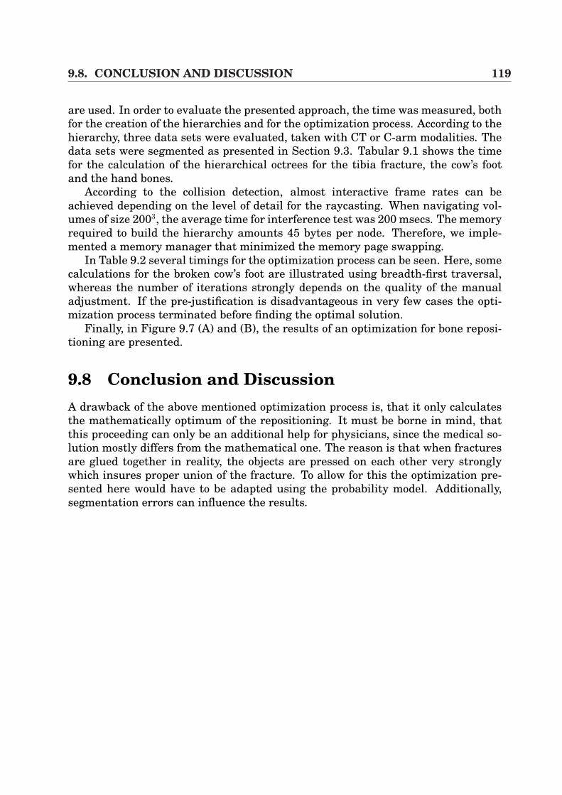
9.8. CONCLUSION AND DISCUSSION 119
are used. In order to evaluate the presented approach, the time was measured, bothfor the creation of the hierarchies and for the optimization process. According to thehierarchy, three data sets were evaluated, taken with CT or C-arm modalities. Thedata sets were segmented as presented in Section 9.3. Tabular 9.1 shows the timefor the calculation of the hierarchical octrees for the tibia fracture, the cow’s footand the hand bones.
According to the collision detection, almost interactive frame rates can beachieved depending on the level of detail for the raycasting. When navigating vol-umes of size 2003, the average time for interference test was 200 msecs. The memoryrequired to build the hierarchy amounts 45 bytes per node. Therefore, we imple-mented a memory manager that minimized the memory page swapping.
In Table 9.2 several timings for the optimization process can be seen. Here, somecalculations for the broken cow’s foot are illustrated using breadth-first traversal,whereas the number of iterations strongly depends on the quality of the manualadjustment. If the pre-justification is disadvantageous in very few cases the opti-mization process terminated before finding the optimal solution.
Finally, in Figure 9.7 (A) and (B), the results of an optimization for bone reposi-tioning are presented.
9.8 Conclusion and DiscussionA drawback of the above mentioned optimization process is, that it only calculatesthe mathematically optimum of the repositioning. It must be borne in mind, thatthis proceeding can only be an additional help for physicians, since the medical so-lution mostly differs from the mathematical one. The reason is that when fracturesare glued together in reality, the objects are pressed on each other very stronglywhich insures proper union of the fracture. To allow for this the optimization pre-sented here would have to be adapted using the probability model. Additionally,segmentation errors can influence the results.
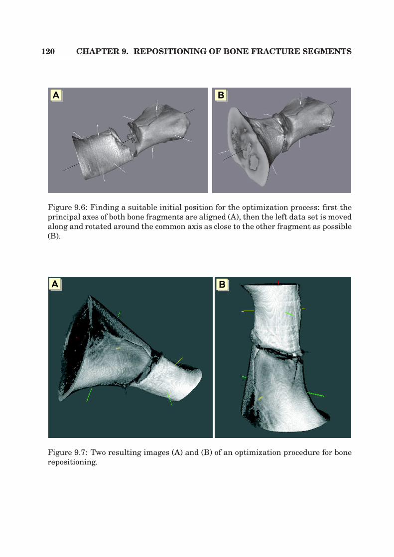
120 CHAPTER 9. REPOSITIONING OF BONE FRACTURE SEGMENTS
AA AB
Figure 9.6: Finding a suitable initial position for the optimization process: first theprincipal axes of both bone fragments are aligned (A), then the left data set is movedalong and rotated around the common axis as close to the other fragment as possible(B).
AA AB
Figure 9.7: Two resulting images (A) and (B) of an optimization procedure for bonerepositioning.

Part IV
Conclusion

122
Chapter 10
Summary
In recent years, surgical interventions have become more and more efficient whichhas been mainly driven by the necessity to accelerate patients’ convalescence andto minimize costs for the Public Health Service due to the ensuring reduction in thelength of time spent in hospital and in operation time for standard interventions.Thus, there is not only an increasing need for pre-operative planning, but also fortransferring such planning information into the operating room. Through the in-vention of navigational hardware and different kinds of patient registration algo-rithms, it is now possible to track surgical tools at the time of intervention, whichhas revolutionized the so-called image-guided surgery. In consequence, there is aremarkable presence of such applications in very different surgical areas, rangingfrom neuronavigation to osseous applications. As far as the latter type of applica-tions is concerned, a pre-operative tool for semi-automatic bone repositioning hasbeen introduced in this work. Surgeons can hereby coarsely adjust the bone frag-ments whilst an optimization procedure is responsible for fine assembly. Apart fromthe large variety of medical fields that have been mentioned above, there are fewintervention schemes which are not yet assisted by navigational hardware for op-eration assistance. Amongst those, minimally invasive visceral surgery, especiallyliver surgery, is a typical example. Although there are some powerful planning toolsfor pre-operative assistance, only very few applications utilize such planning in-formation at the time of intervention. In this context, the technical challenges arethe intra-operative visualization, the extremely important need for real-time perfor-mance and the consideration of the intra-operative medical work flow. Furthermore,soft-tissue deformation has to be considered. In this doctoral thesis applications anddifferent fundamental algorithms for merging laparoscopic video images and tomo-graphic volumes have been worked out.
In order to project three-dimensional data directly onto the surgeon’s view, anew system has been developed which applies electro-magnetic navigation. For im-age overlay purposes, the resulting augmented reality system (ARS) uses 2D multi-texture-based direct volume rendering. Furthermore, fast lens distortion correctionof the heavily distorted laparoscopic images is applied in combination with marker-
124 CHAPTER 10. SUMMARY
based rigid registration for matching the patient and data space. In order to copewith the need for real-time requirements, the graphics hardware had to be exploitedin an efficient manner. Different performance measurements with volumes of var-ious size proved that high interactivity can be kept without any doubt, whilst thesystem is only limited by transfers of video images to the graphics adapter. Forapplication purposes, multiple evaluated planning results from HEPAVISION, a toolfor pre-operative liver planning, have been integrated into the system. Further-more, the software was evaluated in a real intervention simulation as a supple-ment to the clinical routine, whereas hepatic anatomical structures such as liverparenchyma, liver vasculature and vascular territories have been overlaid onto thesurgeon’s view. This augmentation has been utilized for the planning of the incisionpoints for trocars and Veress needle and can be applied to oncologic resections.
In order to consider soft-tissue deformation in the context of laparoscopicvideo image overlay, a fundamentally new algorithm has been developed. Withinthat technique, mutual information is applied for fast and non-rigid registration,whereas calibrated multiple-view video images of an object are taken. Their greyvalue intensities are compared to the virtual view unless a minimized registrationerror is calculated. The basis for calculation is a hardware-based real-time volumedeformation component as a supplement to 3D texture-based approaches, includingefficient local illumination adaption and hierarchical deformation. Thus the vir-tual view can be generated very quickly using direct volume rendering and can beadapted to the real video images. In order to reduce the degrees of freedom duringoptimization, a higher-order deformation model applying 3D tensor product Bezierpatches has been introduced. Furthermore, soft-tissue deformation can be approxi-mated in a fast manner. The system has been evaluated by the application of severalphantoms. Moreover, a new and more elaborate technique has been developed in thecontext of interactive volume deformation, which integrates 3D dependent texturesin conjunction with fragment shaders and multi-texturing.
The techniques described above for the fusion of laparoscopic video images andtomographic volumes all implemented an augmented reality system, providing anextended reality to the surgeon in terms of an image overlay. As an alternative tothose approaches, an algorithm for object texturing has been developed in this work,whereby polygonal isosurfaces that have been extracted from CT volumes are tex-tured by original object video images. This leads to an Augmented Virtuality System(AVS) that efficiently exploits the capabilities of the graphics hardware in order toperform 3D scene exploration of an object. First evaluations of pneumoperitoneumreconstruction and exploration proved high image quality of the virtual object. Forexploration purposes, electro-magnetic navigation and fiducial marker-based regis-tration have been applied to relate the object and the tomographic volume.
10.1. FUTURE CHALLENGES 125
10.1 Future ChallengesThe fusion of video images and tomographic volumes has proven its strength andusability within the operating room in recent years. Classic examples are neuronav-igational applications that visualize segmented trajectories of tumors in a surgicalmicroscope for resection guidance.
As far as image overlay systems are concerned with respect to liver surgery, ap-plications and algorithms that have been presented in this work could provide avery flexible and basic framework for many further possible scenarios and special-purpose operative assistance. Recent publications and conference topics have shownthat image-guided liver surgery assistance will become more and more important inthe near future. Thus, there will be an increasing need for intra-operative applica-tions with real-time requirements and user friendliness.
However, in order to be able to provide accurate navigational aid during inter-vention, future challenges will be focused on the non-rigid registration between theorgan of interest and the pre-operative volume. Currently, ultrasound and laser-ranger scanners are applied in research projects in order to approximate this reg-istration problem, as presented in Section 7.1. As far as the actual clinical rou-tine is concerned, percutaneous ultrasound and mobile C-arm modality are usedin order to control the access to the patient’s body and lesions. Especially in com-bination with tumor ablation therapies, those imaging techniques are the currentstandard. By the introduction of navigation to the surgical tools such as the ul-trasound transducer, precise applications could be created which allow the surgeonto use the 3D image overlays as source of accurate and reliable information dur-ing intervention. Thus, navigated percutaneous radio-frequency therapy (PRFT) orpercutaneous ethanol injection therapy (PEIT) could become very accurate. Fur-thermore, in combination with intra-operative 3D ultrasound, whose image qualityand performance have been increased considerably in recent years, X-ray-based C-arms for guidance purposes could be replaced for such applications. This would leadto reduced radiative levels for both the patient and the physician. Therefore, min-imally invasive liver surgery could evolve into a standard routine for such medicalscenarios.
Furthermore, for oncologic resection applications, not only minimally invasivesurgery could be revolutionized, but also open liver surgery. There are only fewmedical conditions which allow minimally invasive liver resection whilst the maincore of interventions are performed by open surgery. If precise and reliable oncologicresection were possible because of the 3D image overlays of the pre-planning infor-mation, surgical intervention time and efficiency could be accelerated considerablyin the near future.

126 CHAPTER 10. SUMMARY
Bibliography
[1] Developer site of ATI. http://www.ati.com/developer. 3.2, 6.1
[2] T. Akenine-Moller. Real-Time Rendering. A. K. Peters Ltd., 2002. 3.2
[3] Ascension Technology Corporation. http://www.ascension-tech.com. 2.5, 2.2.4,2.2.4
[4] R. Azuma, Y. Baillot, R. Behringer, S. Feiner, S. Julier, and B. MacIntyre.Recent advances in augmented reality. IEEE Computer Graphics and Appli-cations, pages 34–47, 2001. 4.1, 4.1
[5] R. Bajcsy and S. Kovacic. Multiresolution elastic matching. Comp. Vision,Graphics and Image Process., 46:1–21, 1989. 7.4.1
[6] R. Bansal, L. H. Staib, A. Rangarajan, J. Knisely, R. Nath, and J. S. Dun-can. Entropy-based, multiple-portal-to-3DCT registration for prostate radio-therapy using iteratively estimated segmenation. In Proc. of MICCAI, pages567–578. Springer, 1999. 7.1
[7] A. Bauer. Primary THR using the ROBODOC system. CAOS/USA, pages107–108, 1999. 2.2.5
[8] R. A. Beasley, J. D. Stefansic, J. L. Herring, W. A. Bass, A. J. Herline, W. C.Chapman, B. M. Dawant, and R. L. Galloway. Implementation and incorpo-ration of liver 3-D surface renderings into interactive, image-guided hepaticsurgery. In Proc. of SPIE Medical Imaging, pages 282–289. SPIE, 2000. 4.2
[9] D. Bechmann. Space deformation models survey. In Computers & Graphics,pages 571–586, 1994. 6.1
[10] P. J. Besl and N. D. McKay. A method for registration of 3-D shapes. IEEETrans. on Pattern Analysis and Machine Intelligence, 14:239–256, 1992. 4.2,7.1
128 BIBLIOGRAPHY
[11] W. Birkfellner, M. Figl, K. Huber, J. Hummel, R. Hanel, P. Homolka,F. Watzinger, F. Wanschitz, R. Ewers, and H. Bergmann. Calibration of pro-jection parameters in a head-mounted display for augmented reality visual-ization in image-guided therapy. In Proc. of SPIE Medical Imaging, pages471–480. SPIE, 2001. 4.2
[12] W. Birkfellner, M. Figl, K. Huber, F. Watzinger, F. Wanschitz, R. Hanel,A. Wagner, D. Rafolt, R. Ewers, and H. Bergmann. The variosope AR - ahead-mounted operating microscope for augmented reality. In Proc. of MIC-CAI, pages 869–877. Springer, 2000. 4.2
[13] W. Birkfellner, F. Watzinger, and F. Wanschitz. Systematic distortions in mag-netic position digitizers. Med. Phys., 25:2242–2248, 1998. 2.2.4
[14] M. Blackwell, C. Nikou, A. M. DiGioia, and T. Kanade. An image overlaysystem for medical data visualization. Medical Image Analysis, 4(1):67–72,2000. 4.2
[15] H. Bourquain, A. Schenk, F. Link, B. Preim, G. Prause, and H.-O. Peitgen.Hepavision2: A software assistant for preoperative planning in living-relatedliver transplantation and oncologic liver surgery. In Computer Assisted Radi-ology and Surgery, Proc. of CARS, pages 341–346, 2002. 8, 8.1
[16] D. Boyd, F. Banovac, D. Tanaka, J. Tang, D. Lindisch, E. Levy, and K. R.Cleary. Quantification of skin motion over the liver using optical tracking. InProc. of SPIE Medical Imaging. SPIE, 2003. 4.5.1, 8.4
[17] M. Brady, K. Jung, Nguyen HT, and T. Nguyen. Two-phase perspective raycasting for interactive volume navigation. In Visualization ’97, pages 183–ff,1997. 3, 9.4
[18] M. Bro-Nielsen and C. Gramkow. Fast fluid registration of medical images.Comp. Methods Biotech. Biomed. Eng., 3:129–260, 2000. 7.4.1
[19] B. Cabral, N. Cam, and J. Foran. Accelerated Volume Rendering and tomo-graphic reconstruction using texture mapping hardware. In Proc. of 1994Symposium on Volume Visualization, pages 91–98, 1994. 3, 3.3, 9.4
[20] A toolbox for camera calibration for Matlab. http://www.camcal.com. 4.2,4.3.1, 4.3.1, 4.3.1, 4.3.1, 4.6.1
[21] D. M. Cash, T. K. Sinha, W. E. Chapman, R. L. Galloway, and M. I. Miga. Fast,accurate surface acquisition using a laser range scanner for image-guidedliver surgery. In Proc. of SPIE Medical Imaging, pages 100–110. SPIE, 2002.4.2
BIBLIOGRAPHY 129
[22] D. M. Cash, T. K. Sinha, R. L. Galloway, W. C. Chapman, H. Terawaki, andM. I. Miga. Incorporation of a laser range scanner into an image-guided sur-gical system. In Proc. of SPIE Medical Imaging. SPIE, 2003. 7.1
[23] CByon Inc. http://www.cbyon.com. 4.2
[24] G. E. Christensen, R. D. Rabbit, and M. I. Miller. Deformable templates usinglarge deformation kinematics. IEEE Trans. on Image Processing, 5(10):1435–1447, 1996. 7.4.1
[25] C. Chua and U. Neumann. Hardware-accelerated free-form deformations. InProc. of ACM SIGGRAPH/Eurographics Workshop on Graphics Hardware,pages 33–39, 2000. 6.1
[26] M. J. Clarkson, D. Rueckert, D. L. Hill, and D. J. Hawkes. Registration ofmultiple video images to pre-operative CT for image guided surgery. In Proc.of SPIE Medical Imaging, pages 342–352. SPIE, 2000. 1.1, 7.1, 7.3, 7.6, V
[27] J. Cohen, M. Lin, D. Manchoma, and M. Pongami. I-collide: An interactiveand exact collision detection system for large-scale environments. In 1995Symposium on Interactive 3D Graphics, pages 198–196, 1995. 9.5
[28] S. Coquillart. Extended free-form deformations: a sculpturing tool for 3Dgeometric modeling. In Proc. of ACM SIGGRAPH, pages 187–196, 1990. 6.1
[29] S. Cotin, H. Delingette, and N. Ayache. Real-time elastic deformations of softtissues for surgery simulation. IEEE Trans. on Visualization and ComputerGraphics, 5(1):62–73, 1999. 7.4.1
[30] C. Couinaud. Le foie. etudes anatomiques et chirurgicales. 1957. 8.2, 8.2.1
[31] K. Daniilidis. Hand-eye calibration using dual quaternions. InternationalJournal of Robotics Research, 18(3):286–298, 1999. 4.4, 4.4
[32] J. Danskin and P. Hanrahan. Fast algorithms for volume ray tracing. In ACMWorkshop of Volume Visualization, pages 91–98, 1992. 3.1
[33] C. Davatzikos. Spatial transformation and registration of brain images usingelastically deformable models. Computer Vision and Image Understanding,66(2):207–222, 1997. 7.4.1
[34] P. Debevec, Y. Yu, and G. Boshokov. Efficient view-dependent image-basedrendering with projective texture-mapping. 9th Eurographics RenderingWorkshop, pages 105–116, 1998. 1.1, 5.2, 5.3.4, V
130 BIBLIOGRAPHY
[35] D. Dey, D.G. Gobbi, P.J. Slomka, K.J.M. Surry, and T.M. Peters. Automatic fu-sion of freehand endoscopic brain images to three-dimensional surfaces: Cre-ating stereoscopic panoramas. IEEE Trans. on Medical Imaging, 21(1):23–30,2002. 1.1, 5.2, V
[36] R. A. Drebin, L. Carpenter, and P. Hanrahan. Volume Rendering. In Proc. ofACM SIGGRAPH, pages 65–74, 1988. 3, 3.1
[37] G. Eckel. OpenGL volumizer programmer’s guide. SGI Developer Bookshelf,1998. 6.1
[38] C. Eckstein. Interaktive Relokalisierung von Knochenfraktur-Segmenten.Master’s thesis, University of Erlangen-Nuremberg, September 2000. 9.5.2
[39] F. L. Bookstein. Thin-plate splines and the atlas problem for biomedical im-ages. In Information Processing in Medical Imaging, pages 326–342, 1991.7.4.1
[40] A. X. Falcao, K. Jayaram, J. K. Udupa, and F. K. Miyazawa. An ultra-fastuser-steered image segmentation paradigm: Live-wire-on-the-fly. In Proc. ofSPIE Medical Imaging, volume 3661, pages 184–191. SPIE, 1999. 8.3
[41] S. Fang, S. Rajagopalan, S. Huang, and R. Raghavan. Deformable volumeRendering by 3D-texture mapping and octree encoding. In Proc. of IEEE Vi-sualization, pages 73–ff, 1996. 6.1
[42] J. H. D. Fasel, D. Selle, C. J. G. Evertsz, F. Terrier, and H.-O. Peitgen. Segmen-tal anatomy of the liver: Poor correlation with CT. Radiology, 206:151–156,1998. 8.3
[43] O. D. Faugeras, Q. Luong, and S. J. Maybank. Camera self-calibration: Theoryand experiments. In European Conference on Computer Vision, pages 321–334, 1992. 4.1
[44] M. Ferrant, S. Warfield, A. Nabavi, F. Jolesz, and R. Kikinis. Registration of3D intraoperative MR images of the brain using a finite element biomechani-cal model. In Proc. of MICCAI, pages 19–28. Springer, 2000. 7.4.1
[45] H. Feußner and B. Detter. Grundlagen der laparoskopischen Chirurgie. GeorgThieme Verlag Stuttgart, 1995. 2.1.1, 2.1.2, 2.1.2
[46] J. M. Fitzpatrick, J. B. West, and C. R. Maurer. Predicting error in rigid-bodypoint-based registration. IEEE Trans. on Medical Imaging, 17:694–702, 1998.4.5.1
[47] J. Foley, A. van Dam, S. Feiner, and J. Hughes. Computer Graphics, PrincipleAnd Practice. Addison-Weseley, 1993. 6.2.4, 6.2.4
BIBLIOGRAPHY 131
[48] H. Fuchs, M. A. Livingston, R. Raskar, D. Colucci, K. Keller, A. State, J. R.Crawford, P. Rademacher, S. H. Drake, and A. A. Meyer. Augmented realityvisualization for laparoscopic surgery. In Proc. of MICCAI, pages 934–943.Springer, 1998. 4.2
[49] N. Gagvani and D. Silver. Shape-based volumetric collision detection. In Proc.of IEEE Visualization, pages 57–61, 2000. 9.5
[50] N. Garica-Alonso, N. Serrano, and J. Flaquer. Solving the collision detectionproblem. IEEE Computer Graphics and Applications, 13(3):36–43, May 1994.9.5
[51] R. Goecke, J. Weese, and H. Schumann. Fast volume rendering methods forvoxel-based 2D/3D registration - a comparative study. Proc. of InternationalWorkshop on Biomedical Image Registration ’99, pages 89–102, 1999. 7.1
[52] S. J. Goerss, P. J. Kelly, B. Kall, and S. Stiving. A stereotactic magnetic fielddigitizer. Stereotact. Funct. Neurosurg., 63:89–92, 1994. 2.2.4
[53] S. J. Gortler, R. Grzeszczuk, R. Szeliski, and M. F. Cohen. The lumigraph.In Proc. of the 23rd annual conference on Computer graphics and interactivetechniques, pages 43–54, 1996. 5.1, 5.2
[54] S. Gottschalk, M. Lin, and D. Manocha. Obb-tree: A hierarchical structurefor rapid interference detection. In Proc. of ACM SIGGRAPH, pages 171–180,1996. 9.5, 9.5.2, 9.5.2
[55] R. Grzeszczuk, S. Chin, R. Fahrig, H. Abassi, H. Holz, D. Kim, J. Adler, andR. Shahidi. A fluoroscopic X-ray registration process for three-dimensionalsurgical navigation. In Proc. of MICCAI, pages 551–556. Springer, 2000. 7.1
[56] A. R. Gunkel, W. F. Thumfart, and W. Freysinger. Computerunterstutzte 3D-Navigationssysteme - Uberblick und Standortbestimmung. HNO, 48:75–90,2000. 2.2, 2.2.2
[57] J. V. Hajnal, D. L. G. Hill, and D. J. Hawkes. Medical Image Registration.CRC Press LLC, 2001. 7.3, 7.4.1
[58] P. Hastreiter. Registrierung und Visualisierung medizinischer Bilddaten un-terschiedlicher Modalitaten. Arbeitsberichte des Instituts fur mathematischeMaschinen und Datenverarbeitung (Informatik). Friedrich-Alexander Uni-versitat Erlangen-Nurnberg, 1999. 7.1
[59] T. He and A. Kaufman. Collision detection for volumetric objects. In Proc. ofIEEE Visualization, pages 27–34, 1997. 9.5, 9.5.1
132 BIBLIOGRAPHY
[60] H. Hege, T. Hollerer, and D. Stalling. Volume rendering, mathematical foun-dations and algorithmic aspects. Technical Report TR93-7, Konrad-Zuse-Zentrum fur Informationstech., Berlin, 1993. 3.1
[61] J. Heikkila and O. Silven. A four-step camera calibration procedure with im-plicit image correction. IEEE Computer Society Conference on Computer Vi-sion and Pattern Recognition (CVPR’97), pages 1106–1112, 1997. 4.3.1, 4.3.1
[62] J. P. Helferty, C. Zhang, G. McLennan, and W. E. Higgins. New method fornonlinear endoscopic distortion correction. IEEE Trans. on Medical Imaging,20(7), 2001. 4.3.2, 4.3.2
[63] A. J. Herline, J. L. Herring, J. D. Stefansic, W. C. Chapman, R. L. Galloway,and B. M. Dawant. Surface registration for use in interactive image-guidedliver surgery. In Proc. of CAS, pages 11–17, 2000. 4.2
[64] K. Hormann, U. Labsik, M. Meister, and Greiner G. Hierarchical extraction ofiso-surfaces with semi-regular meshes. In Solid Modeling 2002, pages 219–226, 2002. 5.2, 5.3.1
[65] P. M. Hubbard. Interactive collision detection. In Proc. of IEEE Symposiumon Research Frontiers in Virtual Reality, pages 24–32, 1993. 9.5
[66] J. Kajiya and B. Von Herzen. Ray tracing volume densities. In Proc. of ACMSIGGRAPH, pages 165–174, 1984. 3, 3.1
[67] R. E. Kalman. A new approach to linear filtering and predictive problems.Trans. of the ASME - Journal of Basic Engineering, pages 35–45, 1960. 4.2
[68] M. R. Kaus, R. Steinmeier, Th. Sporer, O. Ganslandt, and R. Fahlbusch. Tech-nical accuracy of a neuronavigation system measured with a high precisionmechanical micromanipulator. Neurosurgery, 41(6):1431–1437, 1997. 1, 2.2.5,V
[69] P. J. Kelly, G. J. Alker, and S. Goerss. Computer-assisted stereotactic lasermircosurgery for the treatment of intracranial neoplasms. Journal of Neuro-surgery, 10:324–331, 1982. 4.2
[70] R. Khadem, M. R. Bax, J. A. Johnson, E. P. Wilkinson, and R. Shahidi. Endo-scope calibration and accuracy testing for 3D/2D image registration. In Proc.of MICCAI, pages 1361–1362, 2001. 4.2
[71] R. Kikinis, G. Gleason, T. Moriarty, M. Moore, E. Alexander III, P. Stieg,M. Matsumae, W. Lorensen, H. Cline, and P. Black. Computer-assisted in-teractive three-dimensional planning for neurosurgical procedures. Neuro-surgery, 38(4):640–651, 1998. 1, 2.2.5, V
BIBLIOGRAPHY 133
[72] Y. Kita, D. L. Wilson, and A. Noble. Real-time registration of 3D cerebralvessels to X-ray angiograms. In Proc. of MICCAI, pages 1125–1133. Springer,1999. 7.1
[73] U. Kuhnapfel, H. K. Cakmak, and H. Maass. Endoscopic surgery training us-ing virtual reality and deformable tissue simulation. Computers and Graph-ics, 24(5):671–682, 2000. 7.4.1
[74] Y. Kurzion and R. Yagel. Space deformation using ray deflectors. In Render-ing Techniques ’95 (Proc. of the Sixth Eurographics Workshop on Rendering),pages 21–30, New York, 1995. Springer-Verlag. 6.1
[75] Y. Kurzion and R. Yagel. Interactive space deformation with hardware-assisted rendering. IEEE Computer Graphics & Applications, 17(5), 1997.6.1
[76] P. Lacroute and M. Levoy. Fast volume rendering using a shear-warp factor-ization of the viewing transformation. In Proc. of ACM SIGGRAPH, pages451–458, 1994. 3, 3.1, 7.1
[77] M. Levoy. Efficient ray tracing of volume data. ACM Trans. on Graphics,9(3):245–261, 1990. 3.1
[78] M. Levoy and P. Hanrahan. Light field rendering. In Proc. of ACM SIG-GRAPH, pages 31–42, 1996. 5.1, 5.2
[79] W. E. Lorensen and H. E. Cline. Marching cubes: a high resolution 3D surfaceconstruction algorithm. In Proc. of ACM SIGGRAPH, pages 163–170, 1987.3, 5.3.1
[80] M. E. Leventon and W. M. Wells III and W. E. L. Grimson. Multiple view2D-3D mutual information registration. In Image Understanding Workshop,pages 625–629, 1997. 7.1
[81] R. MacCracken and K. Roy. Free-form deformations with lattices of arbitrarytopology. In Proc. of ACM SIGGRAPH, pages 181 – 188, 1996. 6.1
[82] T. Malzbender. Fourier Volume Rendering. ACM Trans. on Graphics,12(3):233–250, 1993. 3.1
[83] K. Masamune, Y. Masutani, S. Nakajima, I. Sakuma, T. Dohi, H. Iseki, andK. Takakura. Three-dimensional slice image overlay system with accuratedepth perception for surgery. In Proc. of MICCAI, pages 395–402. Springer,2000. 4.2
[84] Medline Plus Health Information. http://medlineplus.gov/. 8.1
134 BIBLIOGRAPHY
[85] J. Meinguet. Multivariate interpolation at arbitrary points made simple.Appl. Math. Phys., 30:292–304, 1999. 7.4.1
[86] M. Meißner, U. Hoffmann, and W. Straßer. Enabling classification and shad-ing for 3D texture based volume rendering using OpenGL and extensions. InVisualization ’99, pages 207–214, 1999. 3, 9.4
[87] M. Meißner, U. Kanus, and W. Straßer. VIZARD II: A PCI-card for real-timeVolume Rendering. In Proc. of ACM SIGGRAPH/Eurographics Workshop onGraphics Hardware, pages 61–67, 1998. 3, 9.4
[88] M. Miga, A. Staubert, K. Paulsen, F. Kennedy, V. Tronnier, D. Roberts, andA. Hartov. Model-updated image-guided neurosurgery: Preliminary analysisusing intraoperative MR. In Proc. of MICCAI, pages 115–124. Springer, 2000.7.4.1
[89] M. I. Miga, D. M. Cash, Z. Cao, R. L. Galloway, B. M. Dawant, , and W. C.Chapman. Intraoperative registration of the liver for image-guided surgeryusing laser range scanning and deformable models. In Prod. of SPIE MedicalImaging. SPIE, 2003. 7.1
[90] P. Milgram and F. Kishino. A taxonomy of mixed reality visual displays.IEICE Trans. Information Systems, E77-D(12):1321–1329, 1994. 4.1
[91] History of minimally invasive surgery. http://www.mssm.edu/misc/history.shtml. 2.1.1
[92] Websburg - the e-surgical reference. http://www.websurg.com/. 2.1.2
[93] Northern Digital Home Page of Products. http://www.ndigital.com. 2.2.3, 2.5,2.2.4, 2.2.4
[94] F. H. Netter. Atlas of the Human Anatomy. Ciba Geigy Corporation, SummitNew Yersey, 8th edition, 1995. 8.1
[95] H. Niemann. Pattern Recognition. Springer, 1990. 2.2.1, 2.2.1
[96] Developer site of NVidia. http://www.nvidia.com/developer. 3.2, 5.4, 6.1, 6.2.4
[97] M. Otte. Elastic registration of fmri data using Bezier-Spline transformtions.IEEE Trans. on Medical Imaging, 20(2):193–206, 2001. 7.4.1
[98] G. Papaionnou, E. Karabassi, and T. Theoharis. Virtual archaelogist: As-sembling the past. IEEE Computer Graphics and Applications, pages 53–59,March/April 2001. 9.1, 9.5
BIBLIOGRAPHY 135
[99] K. Paulsen, M. Miga, F. Kennedy, P. Hoopes, A. Hartov, and D. Roberts. A com-putational model for tracking subsurface tissue deformation during stereotac-tic neurosurgery. IEEE Trans. on Biomed. Eng., 46:213–225, 1999. 7.4.1
[100] J. Peterman, R. Kober, P. Heinze, P. Heekt, and L. Gotzen. Implementationof the CASPAR system in the reconstruction of the ACL. CAOS/USA, pages86–87, 2000. 2.2.5
[101] H. Pfister, J. Hardenbergh, J. Knittel, H. Lauer, and L.Seiler. The VolumeProreal-time ray-casting system. In Proc. of ACM SIGGRAPH, pages 251–260,1999. 3, 9.4
[102] Professional Library from WebMD. http://www.samed.com/. 8.2
[103] B. Preim, H. Bourquain, K. J. Oldhafer D. Selle, and H.-O. Peitgen. Resectionproposals for oncologic liver surgery based on vascular territories. In Com-puter Assisted Radiology and Surgery, Proc. of CARS, pages 353–358, 2002.8.3
[104] B. Preim, F. Ritter, and O. Deussen. A 3D puzzle for learning anatomy. InProc. of MICCAI, pages 750–757. Springer, 1999. 9.1
[105] W. H. Press, S. A. Teukolsky, W. T. Vetterling, and B. P. Flannery. NumericalRecipes in C. Cambridge University Press, 2nd edition, 1992. 4.5.1, 7.3, 9.6
[106] K. Pulli, M. Cohen, T. Duchamp, H. Hoppe, L. Shapiro, and W. Stuetzle. View-based rendering: Visualizing real objects from scanned range and color data.In Proc. of 8th Eurographics Workshop on Rendering, pages 23–34, 1997. 1.1,5.2, 5.3.4, 5.7, V
[107] S. P. Raya and J. K. Udupa. Shape-based interpolation of multidimensionalobjects. IEEE Trans. on Medical Imaging, 9(1):32–42, 1990. 8.3
[108] C. Rezk-Salama. Volume Rendering techniques for general purpose graphicshardware. Arbeitsberichte des Instituts fur mathematische Maschinen undDatenverarbeitung (Informatik). Friedrich-Alexander Universitat Erlangen-Nurnberg, 2002. 3.1, 3.2, 3.3, 3.4, 3.4, 6.3
[109] C. Rezk-Salama, K. Engel, M. Bauer, G. Greiner, and T. Ertl. InteractiveVolume Rendering on standard PC graphics hardware using multi-texturesand multi-stage rasterization. In Proc. of ACM SIGGRAPH/EurographicsWorkshop on Graphics Hardware, pages 169–177, 2000. 3, 3.4, 9.4
[110] C. Rezk-Salama and M. Scheuering. Multitexturbasierte Visualisierung inder Medizin. In Bildverarbeitung fur die Medizin 2001: Algorithmen, Systeme,Anwendungen, pages 137–141. Springer, 2001. 1.1, 3.4, V
136 BIBLIOGRAPHY
[111] C. Rezk-Salama, M. Scheuering, G. Soza, and G. Greiner. Fast volu-metric deformation on general purpose hardware. In Proc. of ACM SIG-GRAPH/Eurographics Workshop on Graphics Hardware, pages 17–24, 2001.1.1, V
[112] F. Ritter, O. Deussen, B. Preim, and T. Strothotte. Virtual 3D puzzles: Anew method for VR based exploration of geometric models. IEEE ComputerGraphics and Applications, 21(5):11–13, 2001. 9.1
[113] F. Ritter, B. Preim, O. Deussen, and T. Strothotte. Using a 3D puzzle as ametaphor for learning spatial relations. In Graphics Interface, pages 171–178, 2000. 9.1
[114] D. W. Roberts, J. W. Strohbehn, J. F. Hatch, W. Murray, and H. Kettenberger.A frameless stereotaxic integration of computerized tomographic imaging inthe operating microscope. Journal of Neurosurgery, 65:545–549, 1986. 4.2
[115] K. Rohr, H. S. Stiehl, R. Sprengel, T. M. Buzug, J. Weese, and M. H. Kuhn.Landmark-based elastic registration using approximating thin-plate splines.IEEE Trans. on Medical Imaging, 20(6):526–534, 2001. 7.4.1
[116] D. Rueckert, L. I. Sonoda, C. Hayes, D. L. G. Hill, M. O. Leach, and D. J.Hawkes. Non-rigid registration using free-form deformations: Application tobreast mr images. IEEE Trans. on Medical Imaging, 18(8):712–721, 1999.7.4.1
[117] T. Salb, J. Brief, O. Burgert, S. Hassfeld, and R. Dillmann. Intraoperativepresentation of surgical planning and simulation results using a stereoscopicsee-through head-mounted display. In Stereoscopic Displays and Applications,part of Photonics West (SPIE), 2000. 4.2
[118] P. Sander, J. Snyder, S. Gortler, and H. Hoppe. Texture mapping progressivemeshes. In Proc. of ACM SIGGRAPH, pages 409–416, 2001. 5.4
[119] F. Sauer, U. J. Schoepf, A. Khamene, S. Vogt, M. Das, and S. G. Silverman.Augmented reality system for ct-guided interventions: system description andinitial phantom trials. In Proc. of SPIE Medical Imaging. SPIE, 2003. 4.2
[120] A. Schenk, S. Behrens, S. A. Meier, P. Mildenberger, and H.-O. Peitgen. Seg-mentierung von Hepatozellularen Karzinomen mit Fuzzy-Connectedness. InBildverarbeitung fur die Medizin, pages 408–412. Springer, 2003. 8.3
[121] A. Schenk, G. Prause, and H.-O. Peitgen. Efficient semiautomatic segmenta-tion of 3D objects in medical images. In Proc. of MICCAI, volume 1935, pages186–195, 2000. 8.3
BIBLIOGRAPHY 137
[122] A. Schenk, G. Prause, and H.-O. Peitgen. Local cost computation for efficientsegmentation of 3D objects with live wire. In Proc. of SPIE Medical Imaging,volume 4322, pages 1357–1364. SPIE, 2001. 8.3
[123] M. Scheuering, U. Labsik, C. Vogelgsang, and G. Greiner. Fusion von trian-gulierten Oberflachen zur 3D-Szenenexploration in der Medizin. In Visual-isierung und Simulation, pages 259–270. SCS, 2003. 1.1, V
[124] M. Scheuering, C. Rezk-Salama, H. Barfuss, A. Schneider, and G. Greiner.Augmented reality based on fast deformable 2D-3D registration for image-guided surgery. In Proc. of SPIE Medical Imaging, pages 436–445. SPIE,2002. 1.1, V
[125] M. Scheuering, C. Rezk-Salama, C. Eckstein, K. Hormann, and G. Greiner.Interactive repositioning of bone fracture segments. In Proc. Vision ModelingAnd Visualization (VMV), pages 499–505. Aka GmbH, 2001. 1.1, V
[126] M. Scheuering, C. Rezk-Salama, K. Barth H. Barfuss, A. Schneider,G. Greiner, G. Wessels, and H. Feussner. Intra-operative Augmented Real-ity mit magnetischer Navigation und multitexturbasiertem Volume Render-ing in der minimal-invasiven Chirurgie. In H. Worn, J. Muhling, C. Vahl, andH. P. Meinzer, editors, Rechner- und sensorgestutzte Chirurgie, pages 83–91.German Informatics Society, 2001. 1.1, 5.6.1, V
[127] M. Scheuering, A. Schneider, A. Schenk, B. Preim, and G. Greiner. Intraoper-ative augmented reality for minimally invasive liver interventions. In Proc.of SPIE Medical Imaging. SPIE, 2003. 1.1, 8.3, 8.5, V
[128] T. Schiemann. Interaktive Verfahren fur deformierende Eingriffe an volu-menbasierten digitalen Korpermodellen. PhD thesis, Technische UniversitatHamburg-Harburg, 1998. 6.1, 7.4.1
[129] A. Schneider, M. Baumgartner, J. Harms, and M. Scheuering. Navigationin der starren und flexiblen Endoskopie. In XXXI. Kongress der DeutschenGesellschaft fur Endoskopie und bildgebende Verfahren e. V., Munchen, 2001.1.1, V
[130] A. Schneider, M. Baumgartner, J. Harms, M. Scheuering, and H. Feussner.Navigation in endoscopic and laparoscopic surgery. In European Society forSurgical Research (ESSR), Santiago de Compostela, Spain, 2001. 1.1, V
[131] A. Schneider, J. Harms, M. Scheuering, F. Haertl, H. Feussner, and G. Wessels.Navigation in der starren und flexiblen Endoskopie. In 35. Jahrestagung derDeutschen Gesellschaft fur Biomedizinische Technik (DGBMT), 2001. 1.1, V
138 BIBLIOGRAPHY
[132] C. Schorr, J. Brief, C. Haag, J. Raczkowsky, S. Haßfeld, J. Muhling,and H. Worn. KasOp - Operationsplanung in der kranio-maxillo-fazialenChirurgie. In H. Worn, J. Muhling, C. Vahl, and H. P. Meinzer, editors,Rechner- und sensorgestutzte Chirurgie, pages 270–278. German InformaticsSociety, 2001. 2.2.5
[133] T. Sederberg and S. Parry. Free-form deformation of solid geometric models.In Proc. of ACM SIGGRAPH, pages 151 –160, 1986. 6.1
[134] M. Segal, C. Korobkin, R. van Widenfelt, J. Foran, and P. Haeberlein. Fastshadows and lighting effects using texture mapping. In Proc. of ACM SIG-GRAPH, pages 249–252, 1992. 5.1
[135] D. Selle and H.-O. Peitgen. Analysis of the morphology and structure of vesselsystems using skeletonization. In Proc. of Medical Imaging, volume 4321,pages 271–281. SPIE, 2001. 8.3
[136] D. Selle, B. Preim, A. Schenk, and H.-O. Peitgen. Analysis of vasculature forliver surgery planning. IEEE Trans. on Medical Imaging, 21(11):1344–1357,2002. 8.3
[137] R. Shahidi. Advances in video laparoscopic surgery using three-dimensionalimage enhanced endoscopy. In MDVista Journal, 2000. 4.2
[138] R. Shahidi. Volumetric image navigation for endoscopic spinal surgery. In 6thAnnual Conference of the International Society for Computer Aided Surgery,2002. 4.2
[139] Y. C. Shiu and S. Ahmad. Calibration of wrist-mounted robotic sensors bysolving homogeneous transform equations of the form AX = XB. IEEE Trans.on Robotics and Automation, 5(1):16–29, 1989. 4.4, 4.4
[140] KARL STORZ GmbH & Co. KG. http://www.karlstorz.de/. 2.2
[141] I. Sutherland. A head-mounted three-dimensional display. Fall Joint Com-puter Conf., Am. Federation of Information Processing Soc. (AFIPS) Conf.Proc., 33:757–764, 1968. 4.1
[142] R. H. Taylor. The role of medical robotics in computer-integrated surgery.In H. Worn, J. Muhling, C. Vahl, and H. P. Meinzer, editors, Rechner- undsensorgestutzte Chirurgie, pages 62–76. German Informatics Society, 2001.2.2.5
[143] AMIRA. http://www.tgs.com. 5.3.1, 5.6.1
BIBLIOGRAPHY 139
[144] R. Tsai. A versatile camera calibration technique for high-accuracy 3D ma-chine vision metrology using off-the-shelf TV cameras and lenses. IEEE Jour-nal of Robotics and Automation, 3:323–344, 1987. 4.2, 4.2, 4.3.1
[145] R. Y. Tsai and R. K. Lenz. A new technique for fully autonomous and efficient3D robotics hand/eye calibration. IEEE Trans. on Robotics and Automation,5(3):345–358, 1989. 4.4, 4.4
[146] J. K. Udupa, S. Samarasekera, and W. A. Barrett. Boundary detection viadynamic programming. In Visualization in Biomedical Computing ’92, pages1087–1091, 1992. 8.3
[147] M. Vetter, P. Hassenpflug, M. Hastenteufel, I. Wolf, M. Thorn, Grenacher,G. M. Richter, W. Lamade, W. Uhl, M. W. Buechler, and H.-P. Meinzer. Real-time deformation modeling and navigation aids for open liver surgery. In Proc.of SPIE Medical Imaging. SPIE, 2003. 7.1, 8.6
[148] P. A. Viola and W. M. Wells III. Alignment by maximization of mutual infor-mation. In Proc. of 5th International Conference on Computer Vision, pages16–23, 1995. 7.1, 7.3
[149] F. Vogt, D. Paulus, and H. Niemann. Highlight substitution in light fields. InProc. of the IEEE International Conference on Image Processing (ICIP), pages637–640, 2002. 5.7, 7.6
[150] E. Watanabe, Y. Mayanagi, Y. Kosugi, S. Manaka, and K. Takakura. Opensurgery assisted by the neuronavigator, a stereotatic, articulated, sensitivearm. Neurosurgery, 28:792–799, 1991. 2.2.2
[151] H. Weghorst, G. Hooper, and D. Greenberg. Improved computational methodsfor ray tracing. ACM Trans. on Graphics, pages 52–69, 1984. 9.5.2
[152] R. Westermann and T. Ertl. Efficiently using graphics hardware in volumerendering applications. Proc. of ACM SIGGRAPH, pages 169–179, 1998. 3,9.4
[153] R. Westermann and C. Rezk-Salama. Real-time volume deformation. In Com-puter Graphics Forum (Eurographics 2001), pages 443–452, 2001. 6.1
[154] L. Westover. Footprint evaluation for volume rendering. In Proc. of ACMSIGGRAPH, pages 367–376, 1990. 3, 3.1
[155] R. G. Willson. Modeling and Calibration of Automated Zoom Lenses. PhDthesis, 1994. 4.2, 4.3.1
[156] C. R. Wirtz and S. Kunze. Neuronavigation: Computerassistierte Neu-rochirurgie. Deutsches Arzteblatt, 95(39), 1998. 1, 2.2.5, V
140 BIBLIOGRAPHY
[157] R. Yagel, D. Cohen, and A. Kaufman. Discrete ray tracing. In IEEE Comp.Graph. Appl., pages 19–28, 1992. 3.1
[158] C. Zhang, J. P. Helferty, G. McLennan, and W. E. Higgins. Nonlinear distortioncorrection in endoscopic video images. IEEE ICIP2000, 2000. 4.3.2, 4.3.2
[159] Z. Zhang. A flexible new technique for camera calibration. IEEE Trans. onPattern Analysis and Machine Intelligence, 22(11):1330–1334, 2000. 4.3.1,4.3.1
[160] K. A. Zucker. Surgical Laparoscopy. Lippincott Williams & Wilkins , 2001.2.1.1, 2.1.2, 8.1
Index
AAbsorption . . . . . . . . . . . . . . . . . . . . . . . . . . 23Acropolis of Athens. . . . . . . . . . . . . . . .110Amira. . . . . . . . . . . . . . . . . . . . . . . . . . . . . . .51Anaesthesia. . . . . . . . . . . . . . . . . . . . .11, 12Arteriovenous malformation (AVM) 93Ascension
MiniBird . . . . . . . . . . . . . . . . . . . . . . . . 17ATI
fragment shader . . . . . . . . . . . . . . . . 29Radeon. . . . . . . . . . . . . . . . . . . . . . . . . .53
Augmented Reality (AR) . . . . . . . . . . . . . 5Augmented Virtuality (AV) . . . . . . . . . 47AVM
see Arteriovenous malformation93Axis-aligned bounding
boxes (AABB) . . . . . . . . . . . . . . 112
BBezier patch . . . . . . . . . . . . . . . . . . . . . . . . 88Bifurcation . . . . . . . . . . . . . . . . . . . . . . . . 107Bile . . . . . . . . . . . . . . . . . . . . . . . . . . . . . . . . 100Bile duct . . . . . . . . . . . . . . . . . . . . . . . . . . . . 99Bone fracture segments . . . . . . . . . . . 109
CC-arm . . . . . . . . . . . . . . . . . . . . . . . . . . . 3, 109Calibration
camera calibration . . . . . . . . . . . . . . 32hand-eyecalibration. . . . . . . . . . . . .38sensor calibration . . . . . . . . . . . . . . . 32
Camera calibrationsee Calibration
Caspar . . . . . . . . . . . . . . . . . . . . . . . . . . . . . . 19Cholecystectomy
laparoscopy cholecystectomy. . . .10
Clipping . . . . . . . . . . . . . . . . . . . . . . . . . . . . 26Collision detection. . . . . . . . . . . . . . . . .112Computed tomography (CT) . . . . . . . . . 3Cytology . . . . . . . . . . . . . . . . . . . . . . . . . . . . 11
cystoscope . . . . . . . . . . . . . . . . . . . . . . . . 9
DDeformation
dependent textures . . . . . . . . . . . . . 74hexahedra deformation . . . . . . . . . 65soft-tissue deformation . . . . . . . . . 85volume deformation . . . . . . . . . . . . 63
Dependent textures readssee Textures
DICOM . . . . . . . . . . . . . . . . . . . . . . . . . . . . . 41Digital reconstructed
radiographs (DRR) . . . . . . . . . . 82Digital subtraction
angiography (DSA). . . . . . . . . .93Direct volume rendering
see RenderingDirectX . . . . . . . . . . . . . . . . . . . . . . . . . 29, 54Distortion correction. . . . . . . . . . . . . . . .32Doppler ultrasound
seeUltrasound . . . . . . . . . . . . . . . . . . 82DSA . . . . . . . . . . . see Digital subtraction
angiographyDuodenum. . . . . . . . . . . . . . . . . . . . . . . . . . 99
EEmission. . . . . . . . . . . . . . . . . . . . . . . . . . . .23Endoscopy
endoscope . . . . . . . . . . . . . . . . . . . . . . . . 9endoscopic tower . . . . . . . . . . . . . . . . 11
Entropy . . . . . . . . . . . . . . . . . . . . . . . . . . . . . 84Extirpation . . . . . . . . . . . . . . . . . . . . . . . . . 12
142 INDEX
FFiducial marker . . . . . . . . . . . . . . . . . . . . 41Finite element modeling . . . . . . . . 83, 87Fragment . . . . . . . . . . . . . . . . . . . . . . . . . . . 26Fragment shader . . . . . . . . . . . . . . . 23, 69Fuzzy-Connectedness . . . . . . . . . . . . . 102
GGallbladder . . . . . . . . . . . . . . . . . 11, 58, 99Goraud . . . . . . . . . . . . . . . . . . . . . . . . . . . . . 71Grid generation. . . . . . . . . . . . . . . . . . . . .50
HHand-eye calibration
see CalibrationHead mounted display (HMD) . . 32, 33Hepatic artery . . . . . . . . . . . . . . . . . . . . . . 99Hepatic vein . . . . . . . . . . . . . . . . . . . . . . . . 99HepaVision . . . . . . . . . . . . . . . . . . . . . 97, 98Hilum. . . . . . . . . . . . . . . . . . . . . . . . . . . . . . .99Hopkins . . . . . . . . . . . . . . . . . . . . . . see StorzHounsfield scale . . . . . . . . . . . . . . . . . . . . 72
IIatrogenic . . . . . . . . . . . . . . . . . . . . . . . . . . . . 3Image-Guided Procedures . . . . . . . . . . . 4Image-guided surgery . . . . . . . . . . . . . . 13Insufflation . . . . . . . . . . . . . . . . . . . . . . . . . 10
LLaparoscopy
diagnostic . . . . . . . . . . . . . . . . . . . . . . . 10laparoscope . . . . . . . . . . . . . . . . . . . . . . 9
Laplace filter . . . . . . . . . . . . . . . . . . . . . . 102Laser range scanner . . . . . . . . . . . . . . . . 83Lightfield . . . . . . . . . . . . . . . . . . . . . . . . . . . 49Lighting . . . . . . . . . . . . . . . . . . . . . . . . . . . . 26
specular. . . . . . . . . . . . . . . . . . . . . . . . .48Live wire . . . . . . . . . . . . . . . . . . . . . . . . . . 102Liver . . . . . . . . . . . . . . . . . . . . . . . . . . . . . . . . 11Lumigraph . . . . . . . . . . . . . . . . . . . . . . . . . 49Lymph node . . . . . . . . . . . . . . . . . . . . . . . . 11
MMagnetic resonance tomography
(MRT) . . . . . . . . . . . . . . . . . . . . . . . . 3Marching cubes . . . . . . . . . . . . . . . . . . . . .50Mass-spring model . . . . . . . . . . . . . . . . . 87Maxillofacial surgery . . . . . . . . . . . . . . . 19Metastasis . . . . . . . . . . . . . . . . . . . . . . . . . . 98Minimally invasive surgery . . . . . . . 3, 9Mixed reality . . . . . . . . . . . . . . . . . . . . . . . 32Multi-texturing . . . . . . . . . . . . . . . . . . . . . 28Mutual information (MI) . . . . . . . . . . . 84
NNavier . . . . . . . . . . . . . . . . . . . . . . . . . . . . . . 87Navigation . . . . . . . . . . . . . . . . . . . . . . . . . . . 4
electro-magnetic . . . . . . . . . . . . . . . . 13electro-mechanic . . . . . . . . . . . . . . . . 13image analysis . . . . . . . . . . . . . . . . . . 13optic . . . . . . . . . . . . . . . . . . . . . . . . . . . . 13robotic . . . . . . . . . . . . . . . . . . . . . . . . . . 13stereo camera . . . . . . . . . . . . . . . . . . . 14
Neuronavigation . . . . . . . . . . . . . . . . . . . . . 4Neurosurgery . . . . . . . . . . . . . . . . . . . . . . . . 4Northern Digital
Optotrak . . . . . . . . . . . . . . . . . . . . . . . . 16Polaris . . . . . . . . . . . . . . . . . . . . . . . . . . 16
NVidiaGeForce . . . . . . . . . . . . . . . . . . . . . . . . . 53register combiners . . . . . . . . . . . . . . 27
OOpenGL. . . . . . . . . . . . . . . . . . . . . . . . .29, 54
glFrustum() . . . . . . . . . . . . . . . . . . 42GL NV register combiners . . 70GL TEXTURESHADERNV. . . . . . . . 76
Oriented bounding boxes (OBB). . .112
PP-buffer . . . . . . . . . . . . . . . . . . . . . . . . . . . . . 55Pancreas . . . . . . . . . . . . . . . . . . . . . . . . . . . . 11Parenchyma . . . . . . . . . . . . . . . 97, 98, 100Parietal . . . . . . . . . . . . . . . . . . . . . . . . . . . . . . 3Parthenon . . . . . . . . . . . . . . . . . . . . . . . . . 110
INDEX 143
Patch . . . . . . . . . . . . . . . . . . . . . . . . . . . . . . . 65Pelvis . . . . . . . . . . . . . . . . . . . . . . . . . . . . . . . 11Percutaneous ethanol
injection therapy (PEIT) . . . 107Peritoneum . . . . . . . . . . . . . . . . . . . . . 11, 57Phong . . . . . . . . . . . . . . . . . . . . . . . . . . . 29, 69Pixel shader . . . . . . . . . . . . . . . . . . . . 23, 28Plenoptic function . . . . . . . . . . . . . . . . . . 49Pneumoperitoneum . . . . . . . . . . . . . 9, 106Portal vein . . . . . . . . . . . . . . . . . . . . . . . . . . 99Powell. . . . . . . . . . . . . . . . . . . . . .85, 86, 117Puzzle . . . . . . . . . . . . . . . . . . . . . . . . . . . . . 110
RRadio-frequency
therapy (RFT) . . . . . . . . . . . . . 107Rasterization . . . . . . . . . . . . . . . . . . . . . . . 26Raycasting. . . . . . . . . . . . . . . . . . . . . . . . . .23Register combiners
see NVidiaRegistration. . . . . . . . . . . . . . . . . . . . . . . . . .4
2D/3D registration . . . . . . . . . . . . . . 81non-rigid registration . . . . . . . . . . . 81rigid registration . . . . . . . . . . . . . . . 40
Renderingdirect volume rendering . . . . . . . . 23image-based. . . . . . . . . . . . . . . . .48, 49
Repositioning. . . . . . . . . . . . . . . . . . . . . .109Rigid registration
see RegistrationRobodoc . . . . . . . . . . . . . . . . . . . . . . . . . . . . .19
SSensor calibration
see CalibrationSeparating axis theorem . . . . . . . . . . 115Shannon-Wiener entropy . . . . . . . . . . . 84Shape-based interpolation . . . . . . . . 102Shear-warp factorization . . . . . . . 23, 82Singular value decomposition
(SVC) . . . . . . . . . . . . . . . . . . . . . . . 41Skeletonization. . . . . . . . . . . . . . . . . . . .102Soft-tissue deformation . . . . . . . . . . . . see
Deformation
Splatting . . . . . . . . . . . . . . . . . . . . . . . . . . . 24Spleen . . . . . . . . . . . . . . . . . . . . . . . . . . . . . . 11Stereo camera
see NavigationStomach . . . . . . . . . . . . . . . . . . . . . . . . . . . . 11Storz
Hopkins . . . . . . . . . . . . . . . . . . . . . . . 103Subdivision . . . . . . . . . . . . . . . . . . . . . . . . . 51
TTexture atlas . . . . . . . . . . . . . . . . . . . . . . . 55Texture-mapping
2D. . . . . . . . . . . . . . . . . . . . . . . . . . .37, 523D . . . . . . . . . . . . . . . . . . . . . . . . . . . . . . 28projective . . . . . . . . . . . . . . . . . . . . . . . 48view-dependent . . . . . . . . . . . . . . . . . 48
Textures3D textures . . . . . . . . . . . . . . . . . . . . . 69dependent textures. . . . . .63, 74, 76
Therapy . . . . . . . . . . . . . . . . . . . . . . . . . . . . . . 4Diagnosis . . . . . . . . . . . . . . . . . . . . . . . . 4Therapy Planning . . . . . . . . . . . . . . . . 4
Transfer function . . . . . . . . . . . . . . . . . . . 23Trauma . . . . . . . . . . . . . . . . . . . . . . . . . . . . . 10Trocar. . . . . . . . . . . . . . . . . . . . . . . . . . .10, 11
UUltrasound . . . . . . . . . . . . . . . . . . . . . . . . 107Ultrasound (US) . . . . . . . . . . . . . . . . . . . . 11Ultrasound(US) . . . . . . . . . . . . . . . . . . . . 13
Doppler . . . . . . . . . . . . . . . . . . . . . . . . . 82Urea . . . . . . . . . . . . . . . . . . . . . . . . . . . . . . . 100Urethra . . . . . . . . . . . . . . . . . . . . . . . . . . . . . . 9
VVeress needle . . . . . . . . . . . . . . . . . . 10, 106Vertex shader. . . . . . . . . . . . . . . . . . . . . . .26Visceral . . . . . . . . . . . . . . . . . . . . . . . . . . . . . . 5Volume of interest . . . . . . . . . . . . . . . . . 117Volumizer. . . . . . . . . . . . . . . . . . . . . . . . . . .64
WWindows . . . . . . . . . . . . . . . . . . . . . . . . . . . . 57

144 INDEX
Part V
German Part

146
Kurzfassung
Die minimal-invasive Chirurgie hat in den letzten Jahren enorme Fortschritte ge-macht, was vor allem durch die enorm verkurzte Genesungszeiten der Patientenbedingt ist. Diese Eingriffe erfordern jedoch viel chirurgische Erfahrung, da dersichtbare Operationsbereich stark begrenzt ist. Zudem wird besonders die Tro-karplatzierung und die Orientierung im Korper des Patienten erschwert. Durchdie Erfindung von Navigationsgeraten wurde jedoch das Tracking von chirurgi-schen Instrumenten und Kameras ermoglicht, was die intra-operative bildgefuhrteChirurgie im Allgemeinen enorm revolutioniert hat. Heutzutage gibt es eine Fullevon Applikationen, die das Navigieren und Fuhren von Werkzeugen mit hoherPrazision gestatten. Diese finden ein breites Einsatzgebiet von der Neuro- bishin zur Knochenchirurgie. Im Bereich der minimal-invasiven Leberchirurgie bietetdie Fusion von laparoskopischen Videobildern mit tomographischen Volumina eineMoglichkeit, intra-operative Eingriffe durch Orientierungshilfen, die auf Naviga-tionshardware basieren, zu unterstutzen. In dieser Dissertation werden verschie-dene Moglichkeiten zur Fusion von Videobildern und tomographischen Voluminaprasentiert. Der Schwerpunkt liegt dabei auf hoher Interaktivitat, weshalb neueTechniken und Fahigkeiten moderner Graphikkarten ausgenutzt werden.
Eine Moglichkeit zur Fusion bieten Augmented Reality Systeme (ARS), diegemaß der Positionierung der chirurgischen Kamera pra-operativ gewonnene In-formation direkt in das Sichtfeld des Chirurgen einblenden. Dabei wird zur Erwei-terung der Realitat ein echtzeitfahiges direktes Volume-Rendering-System einge-setzt, das die Graphikhardware und deren Fragment-Shader-Techniken nutzt. Da-mit konnen das Leberparenchym, Lebergefaße und Segmente fur die onkologischeResektion mittels Bilduberlagerung visualisiert werden. Zudem werden kunstlicheLandmarken und eine rigide Registrierung verwendet. Das System wurde in realenEingriffen erprobt.
Alternativ zum genannten Verfahren konnen die laparoskopischen Videobilderdazu verwendet werden, um den viszeralen Korperbereich mit Echtzeitbildraten zuerkunden. Hierzu wird ein grundlegender Algorithmus vorgestellt, der die Hardwa-rebeschleunigung zur augpunktabhanigen Texturierung ausnutzt.
Weiterhin wird ein fundamentaler und neuer Algorithmus zur schnellen,grauwertbasierten und nichtrigiden 2D/3D-Registrierung eingefuhrt. Dieser Al-gorithmus verwendet Videobilder von mehreren Objektansichten, deformierbares
148
Volume-Rendering und Mutual-Information als Ahnlichkeitsmaß. Das Verfahrenbenotigt dazu ein schnelles und flexibles Modul zum Volume-Rendering, das in-teraktive Volumendeformation erlaubt. Deshalb werden zwei Moglichkeiten vor-gestellt, die erganzend zu 3D-Texturen die Graphikhardware in fortgeschritte-nem Maß ausnutzen. Hierzu gehoren Pixel-Shader-Techniken und 3D-Dependent-Textures.
Obwohl die bildgefuhrte intra-operative Unterstutzung von großer Wichtigkeitist, sind pra-operative Planungsprogramme gleichermaßen von Bedeutung, um mitder individuellen Anatomie des Patienten im Vorfeld der Operation vertraut zu wer-den. Hierzu wird eine Knochenapplikation vorgestellt, die es gestattet, Knochen-frakturelemente aus C-Bogen-Volumina semi-automatisch zusammenzufugen. Da-bei werden die Fragmente zunachst grob vorpositioniert und anschließend mittelseiner Optimierung exakt angepasst.
Inhaltsverzeichnis
Kurzfassung iii
Inhaltsverzeichnis xi
Abbildungsverzeichnis xii
Tabellenverzeichnis xiii
Quellcodes xv
I Einleitung 1
1 Motivation 31.1 Beitrage der Arbeit . . . . . . . . . . . . . . . . . . . . . . . . . . . . . . 51.2 Uberblick . . . . . . . . . . . . . . . . . . . . . . . . . . . . . . . . . . . 7
2 Minimal-invasive Eingriffe und Navigation 92.1 Minimal-invasive Lebereingriffe . . . . . . . . . . . . . . . . . . . . . . 9
2.1.1 Historischer Uberblick . . . . . . . . . . . . . . . . . . . . . . . . 92.1.2 Klinischer Aufbau und Ablauf im Operationssaal . . . . . . . . 10
2.2 Navigation in der bildgestutzten Chirurgie . . . . . . . . . . . . . . . . 132.2.1 Navigation mit Stereokameras . . . . . . . . . . . . . . . . . . . 142.2.2 Elektro-mechanische Navigation und Roboternavigation . . . . 152.2.3 Optische Navigation . . . . . . . . . . . . . . . . . . . . . . . . . 152.2.4 Elektro-magnetische Navigation . . . . . . . . . . . . . . . . . . 172.2.5 Anwendungen . . . . . . . . . . . . . . . . . . . . . . . . . . . . . 18
150
II Fusion von Videobildern und tomographischen Volu-mendaten 21
3 Volume-Rendering 233.1 Direct Volume Rendering . . . . . . . . . . . . . . . . . . . . . . . . . . . 233.2 Grundlagen der Graphikhardware . . . . . . . . . . . . . . . . . . . . . 253.3 Standard 3D-Texturen . . . . . . . . . . . . . . . . . . . . . . . . . . . . 273.4 2D-Multitexturen und Pixelshader . . . . . . . . . . . . . . . . . . . . . 283.5 Zusammenfassung . . . . . . . . . . . . . . . . . . . . . . . . . . . . . . 29
4 Augmented Reality - Fusion von CT und VR 314.1 Einleitung . . . . . . . . . . . . . . . . . . . . . . . . . . . . . . . . . . . 314.2 Verwandte Arbeiten . . . . . . . . . . . . . . . . . . . . . . . . . . . . . . 334.3 Kamerakalibrierung . . . . . . . . . . . . . . . . . . . . . . . . . . . . . 34
4.3.1 Grundlagen . . . . . . . . . . . . . . . . . . . . . . . . . . . . . . 344.3.2 Echtzeit-Bildentzerrung fur Endoskope . . . . . . . . . . . . . . 36
4.4 Sensorkalibrierung . . . . . . . . . . . . . . . . . . . . . . . . . . . . . . 384.5 Augmented Reality und Bilduberlagerung . . . . . . . . . . . . . . . . . 40
4.5.1 Rigide Registrierung . . . . . . . . . . . . . . . . . . . . . . . . . 404.5.2 Systemkomponenten und Zusammenbau . . . . . . . . . . . . . 41
4.6 Ergebnisse . . . . . . . . . . . . . . . . . . . . . . . . . . . . . . . . . . . 424.6.1 Genauigkeit der Registrierung . . . . . . . . . . . . . . . . . . . 424.6.2 Performance . . . . . . . . . . . . . . . . . . . . . . . . . . . . . . 44
4.7 Zusammenfassung und Diskussion . . . . . . . . . . . . . . . . . . . . . 46
5 Augmented Virtuality - 3D-Szenenexploration 475.1 Einleitung . . . . . . . . . . . . . . . . . . . . . . . . . . . . . . . . . . . 475.2 Verwandte Arbeiten . . . . . . . . . . . . . . . . . . . . . . . . . . . . . . 495.3 Algorithmischer Uberblick . . . . . . . . . . . . . . . . . . . . . . . . . . 50
5.3.1 Gittererzeugung . . . . . . . . . . . . . . . . . . . . . . . . . . . . 505.3.2 Kalibrierung . . . . . . . . . . . . . . . . . . . . . . . . . . . . . . 515.3.3 Registrierung . . . . . . . . . . . . . . . . . . . . . . . . . . . . . 515.3.4 Texturierung . . . . . . . . . . . . . . . . . . . . . . . . . . . . . . 52
5.4 Implementierung . . . . . . . . . . . . . . . . . . . . . . . . . . . . . . . 535.5 Ergebnisse . . . . . . . . . . . . . . . . . . . . . . . . . . . . . . . . . . . 565.6 Anwendung . . . . . . . . . . . . . . . . . . . . . . . . . . . . . . . . . . 57
5.6.1 Post-operative Exploration . . . . . . . . . . . . . . . . . . . . . . 575.6.2 Erweiterte Unterstutzung mit Direct Volume Rendering . . . . 58
5.7 Zusammenfassung und Diskussion . . . . . . . . . . . . . . . . . . . . . 58
6 Interaktive Volumendeformation 636.1 Verwandte Arbeiten . . . . . . . . . . . . . . . . . . . . . . . . . . . . . . 646.2 Hexaeder-Deformation . . . . . . . . . . . . . . . . . . . . . . . . . . . . 65
151
6.2.1 Stuckweise lineare Patches . . . . . . . . . . . . . . . . . . . . . 656.2.2 Vertex-Beschrankungen . . . . . . . . . . . . . . . . . . . . . . . 666.2.3 Algorithmische Implementierung . . . . . . . . . . . . . . . . . . 686.2.4 Lokale Beleuchtung und Fragmentshader . . . . . . . . . . . . . 696.2.5 Hierarchiereduktion . . . . . . . . . . . . . . . . . . . . . . . . . 716.2.6 Ergebnisse . . . . . . . . . . . . . . . . . . . . . . . . . . . . . . . 72
6.3 Volumendeformation mit 3D-Dependent-Textures . . . . . . . . . . . . 736.3.1 Implementierung . . . . . . . . . . . . . . . . . . . . . . . . . . . 766.3.2 Ergebnisse . . . . . . . . . . . . . . . . . . . . . . . . . . . . . . . 76
6.4 Zusammenfassung und Diskussion . . . . . . . . . . . . . . . . . . . . . 78
7 Nichtrigide 2D/3D-Registrierung 817.1 Verwandte Arbeiten . . . . . . . . . . . . . . . . . . . . . . . . . . . . . . 827.2 Kalibrierung und Navigation . . . . . . . . . . . . . . . . . . . . . . . . 837.3 Registrierung . . . . . . . . . . . . . . . . . . . . . . . . . . . . . . . . . 837.4 Deformation hoherer Ordnung . . . . . . . . . . . . . . . . . . . . . . . 86
7.4.1 Uberblick . . . . . . . . . . . . . . . . . . . . . . . . . . . . . . . . 877.4.2 Tensorprodukt Bezier-Patches . . . . . . . . . . . . . . . . . . . . 88
7.5 Ergebnisse . . . . . . . . . . . . . . . . . . . . . . . . . . . . . . . . . . . 917.6 Zusammenfassung und Diskussion . . . . . . . . . . . . . . . . . . . . . 92
III Medizinische Anwendungen 95
8 Unterstutzung bei Lebereingriffen 978.1 Motivation . . . . . . . . . . . . . . . . . . . . . . . . . . . . . . . . . . . 988.2 Die Anatomie der Leber und ihre Funktion . . . . . . . . . . . . . . . . 99
8.2.1 Die Anatomie der Leber . . . . . . . . . . . . . . . . . . . . . . . 998.2.2 Die Funktion der Leber . . . . . . . . . . . . . . . . . . . . . . . 100
8.3 Pra-operative Planung . . . . . . . . . . . . . . . . . . . . . . . . . . . . 1018.4 Intra-operativer Aufbau . . . . . . . . . . . . . . . . . . . . . . . . . . . 1038.5 Bewertung . . . . . . . . . . . . . . . . . . . . . . . . . . . . . . . . . . . 1048.6 Diskussion . . . . . . . . . . . . . . . . . . . . . . . . . . . . . . . . . . . 106
9 Repositionierung von Knochenfragmenten 1099.1 Einleitung und Hintergrund . . . . . . . . . . . . . . . . . . . . . . . . . 1099.2 Uberblick . . . . . . . . . . . . . . . . . . . . . . . . . . . . . . . . . . . . 1119.3 Segmentierung . . . . . . . . . . . . . . . . . . . . . . . . . . . . . . . . . 1119.4 Visualisierung . . . . . . . . . . . . . . . . . . . . . . . . . . . . . . . . . 1119.5 Interaktion und Kollisionserkennung . . . . . . . . . . . . . . . . . . . 112
9.5.1 Generierung der Hierarchie . . . . . . . . . . . . . . . . . . . . . 1139.5.2 Kollisionserkennung . . . . . . . . . . . . . . . . . . . . . . . . . 114
9.6 Optimierungsprozess . . . . . . . . . . . . . . . . . . . . . . . . . . . . . 116
152
9.7 Ergebnisse und Diskussion . . . . . . . . . . . . . . . . . . . . . . . . . 119
IV Zusammenfassung 121
10 Zusammenfassung 12310.1 Herausforderungen der Zukunft . . . . . . . . . . . . . . . . . . . . . . 125
Literaturverzeichnis 127
Index 141
V Deutscher Teil 145
Kurzfassung 147
Inhaltsverzeichnis 149
Motivation 153
Zusammenfassung 159
Motivation
Von allen chirurgischen Eingriffen erfuhr die Schlusselloch- oder minimal-invasiveChirurgie in den letzten Jahren den großten Aufschwung. Dies liegt zum einendarin begrundet, dass sich die Instrumentengroße sehr stark verringert hat. Zumanderen hat sich die Eingriffsroutine des gut organisierten OP-Teams innerhalbder Chirurgie mit am weitesten entwickelt. Der effiziente Instrumenteneinsatz unddie geschickte Verwendung der Kamera haben den Zugang zu vielen abdomina-len Korperregionen revolutioniert. Dazu kommt, dass auch grundlegende Vorteiledieser chirurgischen Eingriffsmethoden immer deutlicher werden. In chirurgischenFachkreisen steht mittlerweile unbestritten fest, dass minimal-invasive Therapien
• das parietale1 Trauma reduzieren,
• weniger post-operative Schmerzen verursachen,
• das allgemeine Wohlbefinden der Patienten verbessern,
• bessere kosmetische Resultate erzielen und
• die Aufenthaltsdauer im Krankenhaus verkurzen.
Minimal-invasive Verfahren haben also sowohl fur den Patienten selbst als auchfur das offentliche Gesundheitssystem große Vorteile. Trotzdem darf man nichtubersehen, dass minimal-invasive Chirurgie, die rigide und flexible Endoskope ein-setzt, auch mit operativen Schwierigkeiten verbunden ist. Da der Operateur wedersehend noch tastend direkt in das Operationsfeld eingreifen kann, ist er gezwun-gen, mit einem Kamera-Monitor-System zu arbeiten. Damit sind aber oft Lasionenim Korper des Patienten nicht einfach aufzufinden. Daruber hinaus konnen Ope-rationen nur mit chirurgischen Instrumenten durchgefuhrt werden, die eine Gewe-beklassifikation und -konsistenzbestimmung erschweren. Folglich steigt das Risikoiatrogener2 Krankheiten und die Gefahr, kleinere Befunde zu ubersehen.
Um den Arzt in seinen Entscheidungen bezuglich der richtigen Therapie zu un-terstutzen, werden je nach dem Krankeitsbild des Patienten verschiedene konven-tionelle Bildmodalitaten wie Rontgenprojektion, C-Bogen, Computertomographie
1Die Wand einer Korperhohle betreffend, wandstandig.2Durch arztliche Einwirkung, infolge einer Therapie oder bei der Diagnostik verursacht bzw. ent-
standen.
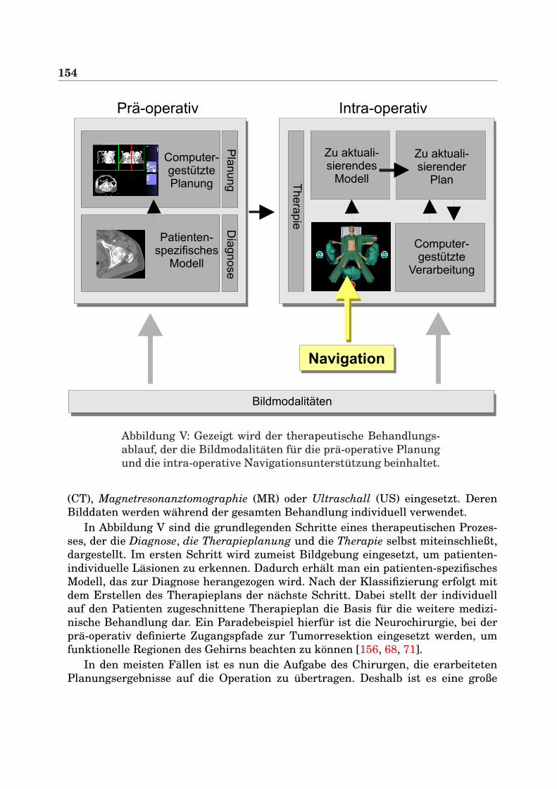
154
Prä-operativ
Computer-gestütztePlanung
Patienten-spezifisches
Modell
Intra-operativ
Computer-gestützte
Verarbeitung
Computer-assistedplanning
Zu aktuali-sierender
Plan
Zu aktuali-sierendes
Modell
Navigation
Bildmodalitäten
Dia
gnose
Pla
nung Th
era
pie
Abbildung V: Gezeigt wird der therapeutische Behandlungs-ablauf, der die Bildmodalitaten fur die pra-operative Planungund die intra-operative Navigationsunterstutzung beinhaltet.
(CT), Magnetresonanztomographie (MR) oder Ultraschall (US) eingesetzt. DerenBilddaten werden wahrend der gesamten Behandlung individuell verwendet.
In Abbildung V sind die grundlegenden Schritte eines therapeutischen Prozes-ses, der die Diagnose, die Therapieplanung und die Therapie selbst miteinschließt,dargestellt. Im ersten Schritt wird zumeist Bildgebung eingesetzt, um patienten-individuelle Lasionen zu erkennen. Dadurch erhalt man ein patienten-spezifischesModell, das zur Diagnose herangezogen wird. Nach der Klassifizierung erfolgt mitdem Erstellen des Therapieplans der nachste Schritt. Dabei stellt der individuellauf den Patienten zugeschnittene Therapieplan die Basis fur die weitere medizi-nische Behandlung dar. Ein Paradebeispiel hierfur ist die Neurochirurgie, bei derpra-operativ definierte Zugangspfade zur Tumorresektion eingesetzt werden, umfunktionelle Regionen des Gehirns beachten zu konnen [156, 68, 71].
In den meisten Fallen ist es nun die Aufgabe des Chirurgen, die erarbeitetenPlanungsergebnisse auf die Operation zu ubertragen. Deshalb ist es eine große
155
Herausforderung, die pra-operativen Daten mit Hilfe von bildgestutzten Verfahrenmit der intra-operativen Situation im OP abzugleichen. Dies erfordert jedoch einpatienten-spezifisches Modell, das wahrend des Eingriffs zu aktualisieren ist. Indiesem Zusammenhang ist die Navigationshardware (vgl. Abschnitt 2.2), die diePosition und Orientierung eines Sensors in einem bestimmten Koordinatensystemermittelt, von großer Bedeutung. Dadurch wird eine intra-operative Navigationsun-terstutzung durch die Anwendung von Registrierungsmethoden, die den Patientenund dessen Datensatz (CT, MR, etc.) miteinander verbinden, moglich gemacht. Die-se Errungenschaft wird von Forschern und Chirurgen gleichermaßen als viel ver-sprechend beurteilt, da nun die Navigation im Korper des Patienten immer praziserwird.
Obwohl bildgestutzte Verfahren sowohl in der Neuronavigation, als auch beiKnochenapplikationen wie der kranio-fazialen Korrektur oder der Ersetzung vonHuftgelenksknochen langst etabliert sind, muss betont werden, dass bei derminimal-invasiven Laparoskopie nur wenige Applikationen zur intra-operativenUnterstutzung bekannt sind, die pra-operative CT- und Planungsdaten in Ver-bindung mit Navigationshardware einsetzen. Fur diese Entwicklung gibt es zweiGrunde. Auf der einen Seite sind es biomechanische Gegebenheiten, die den Ein-satz von bildgefuhrten und anwendungsspezifischen Verfahren erschweren. Diesist bei der Deformierung von Weichgewebe im Bauchraum (z. B. der Leber) der Fall.Dadurch werden zeitaufwendige therapeutische Planungsdaten meistens ungultig,da diese auf pra-operativen Bildern basieren. Auf der anderen Seite muss man aberauch sehen, dass technische Umstande wie das Kamera-Monitor-System und dereingeschrankte Zugang zu den Lasionen einen intra-operativen Einsatz verkompli-zieren.
Diese Dissertation legt ihren Schwerpunkt auf die Unterstutzung von miminal-invasiven viszeralen Eingriffen3, insbesondere auf die Leber. Dazu wurden Algo-rithmen zur Registrierung von Videobildern und 3D-Tomographie-Volumina ent-wickelt. Dabei wurden die Videos mit Laparoskopen (starre Endoskope) aufgenom-men. Die Verfahren bieten ein Grundgerust fur mogliche intra-operative und bild-gestutzte Eingriffe im Zusammenhang mit Augmented-Reality-Systemen (ARS), diepra-operativ gewonnene 3D-Volumen direkt in das Blickfeld des Chirurgen einblen-den. Die projizierten Daten wie Tiefen- und Positionsinformation konnen anschlie-ßend zur Navigationsunterstutzung im Patienten eingesetzt werden.
Da der intra-operative Einsatz von bildgestutzten Systemen unbedingt ho-her Interaktivitat bedarf, stellt diese Arbeit verschiedene Registrierungsmethodenvon Videobildern und 3D-Volumendaten vor, die verkurzte Rechenzeiten in An-spruch nehmen. Um dies zu erreichen, ist eine hardwarebasierte Visualisierungauf marktublichen Graphikkarten unbedingt erforderlich.
3Die Eingeweide betreffend.
156
Eigene BeitrageDas zentrale Thema dieser Dissertation sind verschiedene Aspekte zur Fu-sion von medizinischen Videobildern wie laparoskopische Bilder und 3D-Tomographievolumina. Dazu werden folgende neue Systeme vorgestellt:
AUGMENTED REALITY SYSTEMDieses System wendet die Idee der intra-operativen Augmented-Realityauf die minimal-invasive Leberchirurgie an, die sich, wie im nachstenKapitel ausgefuhrt wird, vollig von anderen chirurgischen Verfahren un-terscheidet. Zu diesem Zweck wird ein sehr leistungsfahiges Volume-Rendering-Modul vorgestellt [110], das zur interaktiven Uberlagerungvon laparoskopischen Videobildern eingesetzt wird. Daruber hinaus wer-den neue Techniken zur schnellen endoskopischen Linsenentzerrung ein-gefuhrt. Um die laparoskopische Kamera und die chirurgischen Instru-mente zu verfolgen, wird ein elektro-magnetisches Navigationssystemverwendet.Das System wurde in mehreren realen Eingriffen in vivo evaluiert [126,130, 129, 131]. Anschließend wurden die Planungsergebnisse eines kli-nisch erprobten Leberplanungssystems (HEPAVISION) integriert, das dasLeberparenchym, das Gefaßsystem, Leberlasionen (Tumore) und Leber-segmente zur onkologischen Resektion zur Verfugung stellt [127].
AUGMENTED VIRTUALITY SYSTEMDieses System erweitert die in [106, 34, 35] vorgestellten Ideenzur Echtzeit-Objekttexturierung und bildet diese auf minimal-invasiveEingriffe ab, wobei Graphikhardware zur Beschleunigung eingesetztwird [123]. Hierbei ist es das Ziel, ein 3D-Modell des Pneumoperitoneumszu generieren, das mit realen laparoskopischen Videobildern texturiertwird. Dieses Modell kann anschließend mit direktem Volume-Renderingfusioniert und zur 3D-Szenenexploration genutzt werden.
ECHTZEIT-VOLUMENDEFORMATIONDas Thema Volumendeformation muss im Zusammenhang mit der Vis-zeralchirurgie und Weichgewebedeformation betrachtet werden. Des-halb wurde ein neues System implementiert, das auf Hardware-Beschleunigung beruht und somit eine Deformation von 3D-Voluminain Echtzeit ermoglicht. Dabei wird ein hexaederbasiertes Deformations-modell vorgestellt, das achsen-parallele Schichten und 3D-Texturen inVerbindung mit geschickter Beleuchtungsberechnung verwendet [111].Alternativ dazu wird eine weitere Methode zur Volumendeformationeingefuhrt, die die Fahigkeiten der Graphikhardware in fortgeschritte-nem Maße unter Verwendung von 3D-Dependent-Textures und Multi-Texturen ausnutzt.
157
SCHNELLE NICHTRIGIDE REGISTRIERUNGDas System der schnellen nichtrigiden Registrierung erweitert funda-mental die Arbeiten von Clarkson et al. [26] zur rigiden grauwertbasier-ten Registrierung von Videobildern mit Oberflachendarstellungen um ei-ne nichtrigide Registrierung [124]. Dieser grundlegend neue Algorithmusbietet die Moglichkeit zur 2D/3D-Registrierung bei stark verkurzter Re-chenzeit. Um korrekte Registrierungsergebnisse zu garantieren, werdenVideobilder verschiedener Ansichten eingesetzt. Eine Deformation vonWeichgewebe wird mit Hilfe von Hexaeder-Volume-Rendering und 3D-Tensorprodukt-Bezier Patches approximiert.
Die genannten Systeme stellen verschiedene Aspekte zur Fusion von Videobildernund tomographischen Volumina vor. Der letzte Beitrag dieser Arbeit widmet sichder chirurgischen Unterstutzung von pra-operativen Planungen:
SYSTEM ZUR REPOSITIONIERUNG VON KNOCHENFRAKTURENIn dieser Applikation wird die Idee eines 3D-Puzzles auf Planungspro-zesse fur die Knochenchirurgie ubertragen. Im Kern erlaubt dieser An-satz eine virtuelle und semi-automatische Repositionierung von Kno-chenfrakturelementen. Dabei werden in einem ersten Schritt die einzel-nen Fragmente grob justiert und anschließend durch die Verwendungvon volumenbasierter Kollisionserkennung und einer Optimierung ex-akt zusammengefugt [125]. Die hierfur eingesetzten Volumina wurdenmit C-Bogen aufgenommen.
Gliederung der ArbeitDiese Dissertation gliedert sich in drei Hauptteile. Der erste Teil gibt eineEinfuhrung in die Problemstellung und grenzt das Thema von anderen bild-gestutzten medizinischen Verfahren ab. Daruber hinaus werden die Grundlagender minimal-invasiven Eingriffe vorgestellt und ein Uberblick uber die derzeitverfugbaren Navigationsgerate gegeben.
Im zweiten Teil dieser Arbeit werden verschiedene Moglichkeiten zur Fusionvon laparoskopischen Videobildern mit tomographischen Volumina mit Hilfe einesAugmented Reality Systems (ARS) beschrieben.
Kapitel 3 stellt das Thema Volume-Rendering vor. Dabei wird auf die Grund-lagen der Graphikhardware eingegangen und erlautert, wie Direktes Volume-Rendering mit Hilfe von Graphikhardware und 2D-Multi-Texturen realisiert wer-den kann. Im sich anschließenden Kapitel 4 wird ein ARS prasentiert, das la-paroskopische Videobilder, Registrierung mit kunstlichen Landmarken, Kamera-und Sensorkalibirierung und eine schnelle Linsenentzerrung einsetzt. Kapitel 5 be-schreibt ein Augmented Virtuality System (AVS), das auf effiziente Art und Weise
158
Videobilder und polygonale Isoflachen fusioniert. Hierbei wird Hardwarebeschleu-nigung und rigide Registrierung eingesetzt. Da in der bildgestutzten Viszeralchir-urgie auch die Deformation von Weichgewebe berucksichtigt werden muss, sind indieser Arbeit nichtlineare Registrierungsmethoden enthalten. In diesem Zusam-menhang befasst sich Kapitel 6 mit zwei Algorithmen zur hardwarebeschleunig-ten Echtzeit-Volumendeformation fur direktes Volume-Rendering. Diese Methodenkonnen dann in Kapitel 7 dazu benutzt werden, um eine grauwertbasierte nichtri-gide Registrierung zwischen Volumendatensatz und Videobild zu erreichen.
Der dritte Hauptteil dieser Arbeit befasst sich mit zwei medizinischen Applika-tionen. Das erste System ist ein intra-operatives ARS, das dem Chirurgen wahrenddes Eingriffs Planungsdaten der Leber zur Verfugung stellt (Kapitel 8). Diese Soft-ware wurde mehrmals in minmal-invasiven Eingriffen eingesetzt. Das zweite Sy-stem dient der interaktiven Repositionierung von Knochenfragmenten, deren Volu-mina mit C-Bogen aufgenommen wurden (Kapitel 9). Dabei werden die Fragmentevom Arzt fur Planungszwecke interaktiv justiert.
Der Schlussteil dieser Arbeit fasst die wichtigsten Punkte dieser Dissertation zu-sammen und geht auf mogliche Zukunftsvisionen im Bereich der minimal-invasivenLeberchirurgie ein.
Zusammenfassung
Operative Eingriffe am Patienten werden seit einigen Jahren immer effizienter. EinGrund hierfur ist vor allem das Bestreben, die Patientengenesung zu beschleuni-gen und gleichzeitig die Kosten fur das Gesundheitssystem durch kurzere Kran-kenhausaufenthalte oder verkurzte Operationszeiten bei Standardeingriffen zu re-duzieren. Um dieser Forderung gerecht zu werden, ist sowohl eine erhohte pra-operative Planung, als auch eine sehr gute Abbildung dieser Planungen im OP un-bedingt notwendig.
Durch die Erfindung von Navigationsgeraten und verschiedener Patientenregi-strierungsmethoden wurde es moglich, chirurgische Werkzeuge intra-operativ zuverfolgen. Dadurch wurde die Entwicklung der so genannten bildgefuhrten Chir-urgie (Image-guided Surgery) enorm revolutioniert, was sich heutzutage in einerstarken Prasenz derartiger Applikationen in vielen Bereichen der Chirurgie nieder-schlagt. Diese reichen von neurochirurgischen Navigationen bis hin zu Knochen-applikationen. Fur letztere wurde in dieser Arbeit ein Planungssystem vorgestellt,das es virtuell am Bildschirm gestattet, semiautomatisch Knochenfragmente zu-sammenzufugen. Unterstutzt wird der Arzt hierbei durch einen Optimierungspro-zess, der die Feinjustierung der Knochensplitter ubernimmt.
Neben den genannten Bereichen der bildgefuhrten Chirurgie existiert jedoch ei-ne Reihe weiterer Eingriffsarten, die noch kaum von der Navigation beruhrt sind.Zu diesen gehort die minimal-invasive Viszeralchirurgie, speziell die Leberchirur-gie. Fur diesen Bereich existieren zwar sehr leistungsfahige Planungsapplikationenfur den pra-operativen Gebrauch, ein intra-operativer Einsatz dieser Planungser-gebnisse ist jedoch nahezu nicht vorhanden. Die technischen Schwierigkeiten lie-gen zum einen in der visuellen Aufbereitung der intra-operativen Unterstutzung,als auch in der wichtigen Echtzeitanforderung und dem medizinischen Workflowim OP. Zudem muss die Organverschiebung berucksichtigt werden. Das Ziel dieserArbeit war es deshalb, Anwendungen und Grundlagenalgorithmen zu erarbeiten,um laparoskopische Videobilder mit tomographischen Volumina zu fusionieren.
Es wurde zunachst ein neues System entwickelt, das unter elektro-magnetischerNavigation dreidimensionale Daten direkt in das Sichtfeld des Operateurseinblendet. Das entstandene Augmented Reality System (ARS) benutzt alsUberblendungstechnik ein 2D-multi-texturbasiertes direktes Volume-Rendering-System, eine schnelle hardwarebasierte Linsenentzerrung der stark verzerrten la-
160
paroskopischen Videobilder und markerbasierte rigide Registrierung zwischen Pa-tient und Volumendatensatz. Eine effiziente Ausnutzung der Graphikhardware istdabei von enormer Wichtigkeit, um den Echtzeitanforderungen gerecht zu werden.Verschiedene Leistungsmessungen mit Datensatzen unterschiedlicher Große zeig-ten, dass dies problemlos eingehalten werden kann und uberwiegend durch den Vi-deobildtransfer zur Graphikkarte limitiert ist. Unter Verwendung von medizinischevaluierten Planungsdaten aus HEPAVISION fur die pra-operative Leberoperations-planung konnte das System in einer realen Interventionssimulation als Erganzungzur klinischen Routine erfolgreich eingesetzt werden. Dabei wurden anatomischeStrukturen der Leber wie Leberparenchym, Lebergefaße und Lebersegmente in dasSichtfeld des Operateurs eingeblendet. Diese Daten konnen vor allem zur Trokar-und Veressnadelplanung, als auch zur onkologischen Resektion eingesetzt werden.
Um bei realen laparoskopischen Videobildern Organdeformationen bei derUberlagerung mitberucksichtigen zu konnen, wurde ein fundamental neuer Al-gorithmus entwickelt, der unter Verwendung von Mutual Information eineschnelle nichtrigide 2D/3D-Registrierung erlaubt. Dabei werden von einem zuuberlagerndem Objekt mehrere kalibrierte Videobilder aufgenommen und dieGrauwerte der Bilder mit den zugehorigen virtuell erzeugten Ansichten solangeverglichen, bis ein Ergebnis mit minimiertem Fehler erzeugt wird. Grundvorausset-zung hierfur ist ein auf Graphikhardware basierendes Echtzeitdeformationsmodell,das unter Einsatz von 3D-Texturen, geschickter lokaler Beleuchtungsadaption undhierarchischer Deformation die virtuelle Ansicht per direktem Volume-Renderinggeneriert. Das virtuelle 3D-Modell passt sich somit durch schnelle Berechnung denVorgaben der Videobilder an. Um bei der Optimierung die Freiheitsgrade und somitden Rechenaufwand zu reduzieren, wurde ein Deformationsmodell hoherer Ord-nung unter Verwendung von 3D-Tensorprodukt Bezierpatches eingefuhrt. Dies ge-stattet eine schnelle Approximation von Weichgewebe. Erste Evaluierungen wurdenanhand von Phantomen durchgefuhrt. Die Visualisierungskomponente des Systemsarbeitet dabei mit achsen-parallelen Schichten. In diesem Zusammenhang wurdezusatzlich eine neue technisch elegantere Losung erarbeitet, die 3D-Dependent-Textures in Verbindung mit Fragment Shader und Multi-Texturen nutzt.
Die bisher beschriebenen Techniken zur Fusionierung von laparoskopischen Vi-deobildern mit tomographischen Volumina haben ein Augmented Reality Systemrealisiert, das eine Uberlagerung, somit eine erweiterte Realitat fur den Chirur-gen generiert. Alternativ zu dieser Vorgehensweise wurde in dieser Arbeit ein Al-gorithmus entwickelt, der polygonale Isoflachen, die aus CT Volumina gewonnenwerden, mit originalen Videobildern texturiert. Somit ist ein Augmented VirtualitySystem (AVS) entstanden, das unter effizienter Ausnutzung von Graphikhardwa-re eine 3D-Szenenexploration eines Objektes erlaubt. Erste sehr viel versprechen-de Evaluierungsschritte zur Rekonstruktion des Bauchraumes zeigten, dass hoheBildqualitaten des virtuellen Objektes erzielt werden konnten. Eingesetzt wurdenhierzu sowohl elektro-magnetische Navigation als auch markerbasierte rigide Re-gistrierung zwischen Objekt und tomographischen Volumen.
161
AusblickDie Fusion von Videobildern mit tomographischen Volumina hat in den letzten Jah-ren ihre Leistungsfahigkeit und Verwendbarkeit im Operationssaal unter Beweisgestellt. Als Paradebeispiel sind hierbei Anwendungen in der Neuronavigation zunennen, bei denen vorsegmentierte Umrisse von Tumoren in ein Mikroskop fur dieResektion eingeblendet werden.
Die Applikationen und Algorithmen, die in dieser Arbeit im Zusammenhang mitder Leberchirurgie vorgestellt wurden, konnten als ein flexibles und grundlegen-des Gerust fur viele weitere Szenarien und spezielle Eingriffsunterstutzungen die-nen. Neueste Veroffentlichungen und Konferenzbeitrage haben bewiesen, dass bild-gefuhrte Unterstutzung in der Leberchirurgie in der nahen Zukunft immer wichti-ger wird. Aus diesem Grund wird eine steigende Nachfrage nach intra-operativenApplikationen entstehen, die Echtzeitanforderung und Benutzerfreundlichkeit for-dern.
Damit es jedoch moglich sein wird, genaue Navigationsshilfen wahrend des Ein-griffs zur Verfugung zu stellen, liegt die zukunftige Herausforderung wohl in dernichtrigiden Registrierung des Organs mit dem pra-operativen Volumendatensatz.In derzeitigen Forschungsprojekten werden Ultraschall oder Laser-Range-Scannerverwendet, um sich diesem Registrierungsproblem anzunahern (vgl. Abschnitt 7.1).In der heutigen klinischen Routine hingegen werden perkutaner Ultraschall odermobile C-Bogen verwendet, um einen kontrollierenden Zugang zum Korper des Pa-tienten oder zu dessen Lasionen zu erreichen. Besonders aber bei Tumor-Ablationensind diese Bildgebungen aktueller Standard. Durch die Einfuhrung von Navigati-on an chirurgischen Instrumenten wie z. B. am Ultraschallkopf konnen sehr ge-naue Applikationen entwickelt werden, die dem Chirurgen die Moglichkeit bie-ten, 3D-Uberlagerungen als exakte und verlassliche Zusatzinformation wahrenddes Eingriffs zu nutzen. Dies gilt auch fur die navigierte Hochfrequenz-Ablationoder die perkutane Ethanol-Ablation. Zudem kann zusammen mit 3D-Ultraschall,dessen Bildqualitat und Leistung in den letzten Jahren enorm verbessert wur-de, rontgenbasierte C-Bogenbildfuhrung vermindert werden, falls eine schnellenichtrigide Registrierung zwischen der Leber und dem tomographischen Volumenmoglich ist. Dies wurde die Strahlenbelastung sowohl fur den Patienten, als auchfur den Arzt enorm reduzieren. Folglich kann die minimal-invasive Leberchirurgieverstarkt zu einem Standardeingriff weiterentwickelt werden.
Im Zusammenhang mit onkologischen Resektionsapplikationen konnte nichtnur die minimal-invasive Chirurgie, sondern auch die offene Leberchirurgie revo-lutioniert werden, da das Gros an Resektionseingriffen offen durchgefuhrt wird.Sollte exakte und verlassliche Resektion auch hier aufgrund der 3D-Uberlagungenvon Planungsergebnissen moglich sein, so konnte sich in der nahen Zukunft dieOperationszeit und deren Effizienz enorm beschleunigen.

162
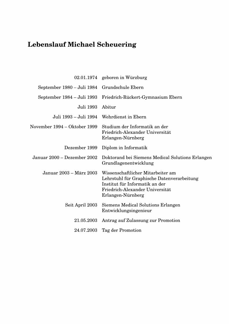
Lebenslauf Michael Scheuering
02.01.1974 geboren in Wurzburg
September 1980 – Juli 1984 Grundschule Ebern
September 1984 – Juli 1993 Friedrich-Ruckert-Gymnasium Ebern
Juli 1993 Abitur
Juli 1993 – Juli 1994 Wehrdienst in Ebern
November 1994 – Oktober 1999 Studium der Informatik an derFriedrich-Alexander UniversitatErlangen-Nurnberg
Dezember 1999 Diplom in Informatik
Januar 2000 – Dezember 2002 Doktorand bei Siemens Medical Solutions ErlangenGrundlagenentwicklung
Januar 2003 – Marz 2003 Wissenschaftlicher Mitarbeiter amLehrstuhl fur Graphische DatenverarbeitungInstitut fur Informatik an derFriedrich-Alexander UniversitatErlangen-Nurnberg
Seit April 2003 Siemens Medical Solutions ErlangenEntwicklungsingenieur
21.05.2003 Antrag auf Zulassung zur Promotion
24.07.2003 Tag der Promotion

164