Embed Size (px)
DESCRIPTION
A new fusion cladding process guards against wear, corrosion, and excessive temperatures to protect pipelines and oilfield component surfaces in harsh environments.
Citation preview
ADVANCED MATERIALS & PROCESSES • JULY 2013 17
Fusion Cladding Prevents Pipeline Wear and Corrosion
Corrosion costs $2.2 trillion annually tothe global economy, with nearly $1.2trillion to the oil and gas industry alone.
To satisfy the ever increasing demand for energy,oil and gas companies continue to move furtheroffshore and into deeper waters to produce fuelfrom challenging reserves using highly corrosiveprocesses. These difficult conditions demandcorrosion-resistant pipes, components, andequipment that can withstand an assault of caus-tic fluids at very high temperatures and pres-sures. Parts made from corrosion-resistant cladsteel are an optimal solution given the economicrisk and safety concerns involved.
However, popular cladding technologiessuch as mechanical lining and roll bonding suf-fer from major concerns involving integrity andsupply. These matters are further aggravated bythe need for thick-walled and large-diameterpipes in heavy demand in the Gulf of Mexico andAsia-Pacific regions.
To confront these issues, MesoCoat Inc. de-veloped a new cladding technique. The com-pany’s CermaClad high-energy-density fusioncladding process addresses most of the concernsassociated with current technologies: Theprocess enables application of metallurgicallybonded cladding over large areas at high produc-tion rates, and without the size, thickness, andreeling/installation limitations of other methods.
How it works
Central to the CermaClad process is a highintensity arc lamp that melts and fuses variousmaterials onto metals. Oak Ridge National Lab-oratory (ORNL), Tenn., was the first to realizethe potential of the arc lamp for surface engi-neering and coatings, and began R&D efforts
in the early 2000s. After ORNL demonstratedthe proof-of-concept for CermaClad, Meso-Coat further developed and transitioned thetechnology to a commercial scale. What wasonce a lamp with a 4 × 4-ft footprint wasminiaturized to slide into pipes with diame-ters as small as 8-in. for cladding. The processmelts and fuses corrosion- and heat-resistantmaterials onto the interior walls of pipes thatcarry abrasive slurries, high-sulfur crude oil,and similar products. This article describesthe equipment, operation, materials, and coat-ing characterization involved.
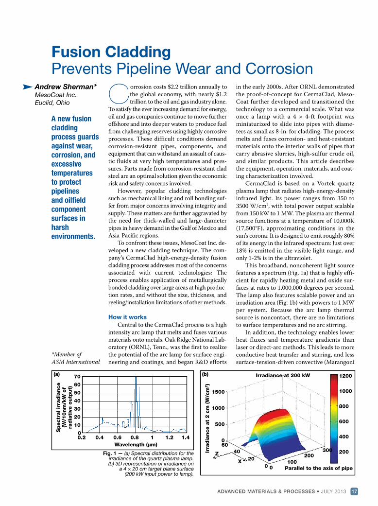
CermaClad is based on a Vortek quartzplasma lamp that radiates high-energy-densityinfrared light. Its power ranges from 350 to
3500 W/cm2, with total power output scalablefrom 150 kW to 1 MW. The plasma arc thermalsource functions at a temperature of 10,000K(17,500°F), approximating conditions in thesun’s corona. It is designed to emit roughly 80%of its energy in the infrared spectrum: Just over18% is emitted in the visible light range, andonly 1-2% is in the ultraviolet.
This broadband, noncoherent light sourcefeatures a spectrum (Fig. 1a) that is highly effi-cient for rapidly heating metal and oxide sur-faces at rates to 1,000,000 degrees per second.The lamp also features scalable power and anirradiation area (Fig. 1b) with powers to 1 MWper system. Because the arc lamp thermalsource is noncontact, there are no limitationsto surface temperatures and no arc stirring.
In addition, the technology enables lowerheat fluxes and temperature gradients thanlaser or direct-arc methods. This leads to moreconductive heat transfer and stirring, and lesssurface-tension-driven convective (Marangoni
Andrew Sherman*
MesoCoat Inc.
Euclid, Ohio
A new fusion
cladding
process guards
against wear,
corrosion, and
excessive
temperatures
to protect
pipelines
and oilfield
component
surfaces in
harsh
environments.
*Member of
ASM International
Fig. 1 — (a) Spectral distribution for theirradiance of the quartz plasma lamp.(b) 3D representation of irradiance on
a 4 × 20 cm target plane surface (200 kW input power to lamp).
(a) (b)70
60
50
40
30
20
10
0
Spectr
al ir
radia
nce
(W/1
0nm
/kW
of
radia
tive o
utp
ut)
0.2 0.4 0.6 0.8 1 1.2 1.4
Wavelength (µm)
0100
200300
60
40
20
0 Parallel to the axis of pipe
1200
1000
800
600
400
200Z
X
1500
1000
500
0
Irradiance at 200 kW
Irra
dia
nce a
t 2 c
m (W
/cm
2)
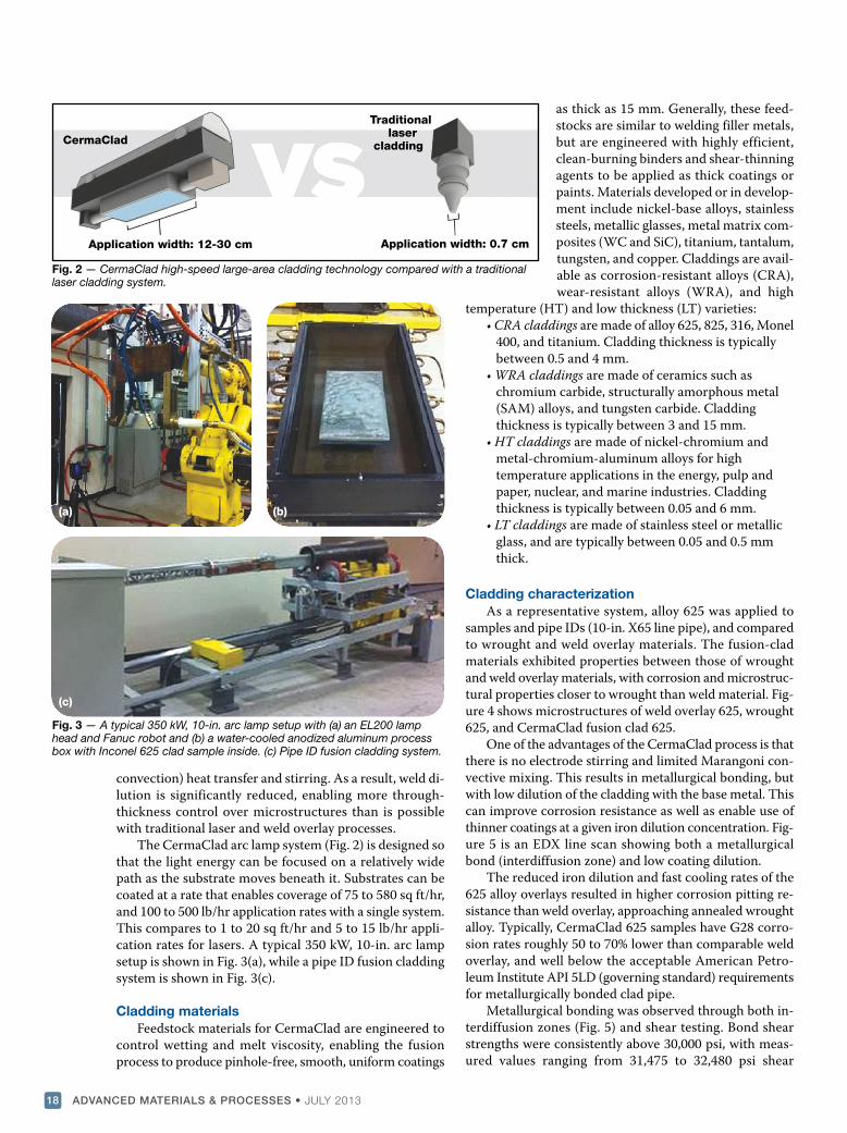
convection) heat transfer and stirring. As a result, weld di-lution is significantly reduced, enabling more through-thickness control over microstructures than is possiblewith traditional laser and weld overlay processes.
The CermaClad arc lamp system (Fig. 2) is designed sothat the light energy can be focused on a relatively widepath as the substrate moves beneath it. Substrates can becoated at a rate that enables coverage of 75 to 580 sq ft/hr,and 100 to 500 lb/hr application rates with a single system.This compares to 1 to 20 sq ft/hr and 5 to 15 lb/hr appli-cation rates for lasers. A typical 350 kW, 10-in. arc lampsetup is shown in Fig. 3(a), while a pipe ID fusion claddingsystem is shown in Fig. 3(c).
Cladding materials
Feedstock materials for CermaClad are engineered tocontrol wetting and melt viscosity, enabling the fusionprocess to produce pinhole-free, smooth, uniform coatings
as thick as 15 mm. Generally, these feed-stocks are similar to welding filler metals,but are engineered with highly efficient,clean-burning binders and shear-thinningagents to be applied as thick coatings orpaints. Materials developed or in develop-ment include nickel-base alloys, stainlesssteels, metallic glasses, metal matrix com-posites (WC and SiC), titanium, tantalum,tungsten, and copper. Claddings are avail-able as corrosion-resistant alloys (CRA),wear-resistant alloys (WRA), and high
temperature (HT) and low thickness (LT) varieties:• CRA claddings are made of alloy 625, 825, 316, Monel
400, and titanium. Cladding thickness is typically between 0.5 and 4 mm.
• WRA claddings are made of ceramics such aschromium carbide, structurally amorphous metal (SAM) alloys, and tungsten carbide. Cladding thickness is typically between 3 and 15 mm.
• HT claddings are made of nickel-chromium and metal-chromium-aluminum alloys for high temperature applications in the energy, pulp and paper, nuclear, and marine industries. Cladding thickness is typically between 0.05 and 6 mm.
• LT claddings are made of stainless steel or metallic glass, and are typically between 0.05 and 0.5 mm thick.
Cladding characterization
As a representative system, alloy 625 was applied tosamples and pipe IDs (10-in. X65 line pipe), and comparedto wrought and weld overlay materials. The fusion-cladmaterials exhibited properties between those of wroughtand weld overlay materials, with corrosion and microstruc-tural properties closer to wrought than weld material. Fig-ure 4 shows microstructures of weld overlay 625, wrought625, and CermaClad fusion clad 625.
One of the advantages of the CermaClad process is thatthere is no electrode stirring and limited Marangoni con-vective mixing. This results in metallurgical bonding, butwith low dilution of the cladding with the base metal. Thiscan improve corrosion resistance as well as enable use ofthinner coatings at a given iron dilution concentration. Fig-ure 5 is an EDX line scan showing both a metallurgicalbond (interdiffusion zone) and low coating dilution.
The reduced iron dilution and fast cooling rates of the625 alloy overlays resulted in higher corrosion pitting re-sistance than weld overlay, approaching annealed wroughtalloy. Typically, CermaClad 625 samples have G28 corro-sion rates roughly 50 to 70% lower than comparable weldoverlay, and well below the acceptable American Petro-leum Institute API 5LD (governing standard) requirementsfor metallurgically bonded clad pipe.
Metallurgical bonding was observed through both in-terdiffusion zones (Fig. 5) and shear testing. Bond shearstrengths were consistently above 30,000 psi, with meas-ured values ranging from 31,475 to 32,480 psi shear
ADVANCED MATERIALS & PROCESSES • JULY 201318
Fig. 2 — CermaClad high-speed large-area cladding technology compared with a traditionallaser cladding system.
(a) (b)
(c)
Fig. 3 — A typical 350 kW, 10-in. arc lamp setup with (a) an EL200 lamphead and Fanuc robot and (b) a water-cooled anodized aluminum processbox with Inconel 625 clad sample inside. (c) Pipe ID fusion cladding system.
CermaClad
Application width: 12-30 cm
Traditional laser
cladding
Application width: 0.7 cm
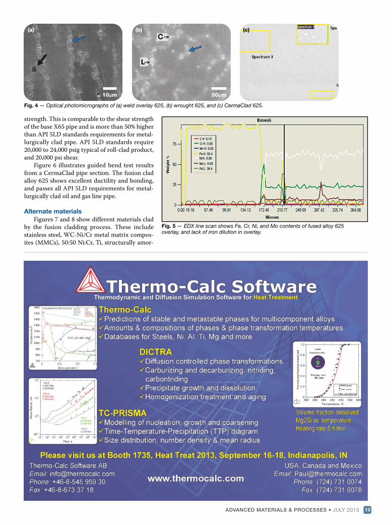
strength. This is comparable to the shear strengthof the base X65 pipe and is more than 50% higherthan API 5LD standards requirements for metal-lurgically clad pipe. API 5LD standards require20,000 to 24,000 psig typical of roll-clad product,and 20,000 psi shear.
Figure 6 illustrates guided bend test resultsfrom a CermaClad pipe section. The fusion cladalloy 625 shows excellent ductility and bonding,and passes all API 5LD requirements for metal-lurgically clad oil and gas line pipe.
Alternate materials
Figures 7 and 8 show different materials cladby the fusion cladding process. These includestainless steel, WC-Ni/Cr metal matrix compos-ites (MMCs), 50:50 Ni:Cr, Ti, structurally amor-
ADVANCED MATERIALS & PROCESSES • JULY 2013 19
(a) (b) (c)
10�m 50�m
Fig. 4 — Optical photomicrographs of (a) weld overlay 625, (b) wrought 625, and (c) CermaClad 625.
Fig. 5 — EDX line scan shows Fe, Cr, Ni, and Mo contents of fused alloy 625 overlay, and lack of iron dilution in overlay.
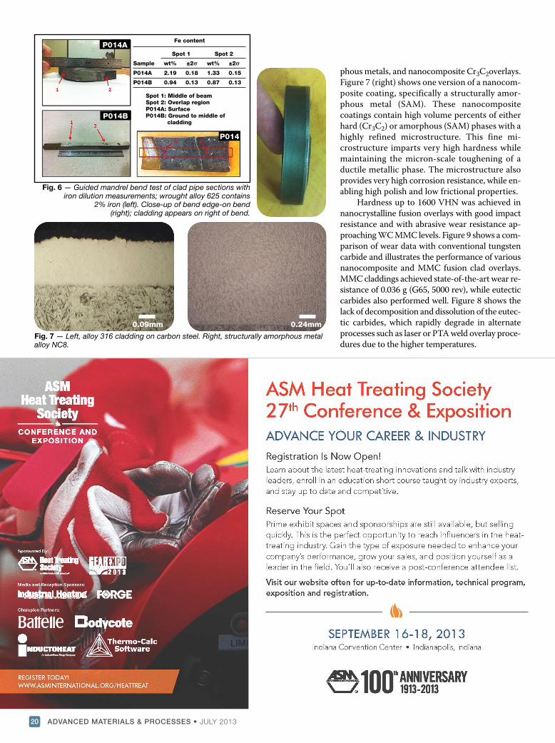
phous metals, and nanocomposite Cr3C2overlays.Figure 7 (right) shows one version of a nanocom-posite coating, specifically a structurally amor-phous metal (SAM). These nanocompositecoatings contain high volume percents of eitherhard (Cr3C2) or amorphous (SAM) phases with ahighly refined microstructure. This fine mi-crostructure imparts very high hardness whilemaintaining the micron-scale toughening of aductile metallic phase. The microstructure alsoprovides very high corrosion resistance, while en-abling high polish and low frictional properties.
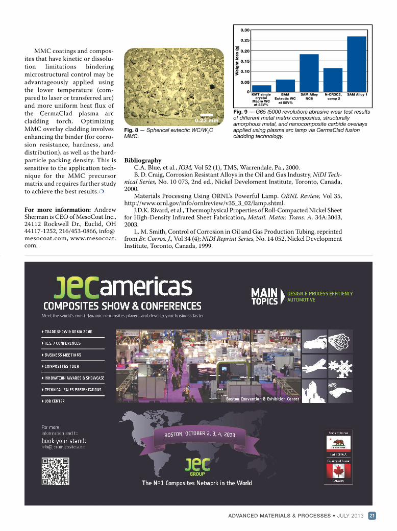
Hardness up to 1600 VHN was achieved innanocrystalline fusion overlays with good impactresistance and with abrasive wear resistance ap-proaching WC MMC levels. Figure 9 shows a com-parison of wear data with conventional tungstencarbide and illustrates the performance of variousnanocomposite and MMC fusion clad overlays.MMC claddings achieved state-of-the-art wear re-sistance of 0.036 g (G65, 5000 rev), while eutecticcarbides also performed well. Figure 8 shows thelack of decomposition and dissolution of the eutec-tic carbides, which rapidly degrade in alternateprocesses such as laser or PTA weld overlay proce-dures due to the higher temperatures.
ADVANCED MATERIALS & PROCESSES • JULY 201320
Fig. 6 — Guided mandrel bend test of clad pipe sections withiron dilution measurements; wrought alloy 625 contains
2% iron (left). Close-up of bend edge-on bend(right); cladding appears on right of bend.
Fig. 7 — Left, alloy 316 cladding on carbon steel. Right, structurally amorphous metalalloy NC8.
0.09mm 0.24mm
Fe content
Spot 1 Spot 2
Sample wt% ±2� wt% ±2��
P014A 2.19 0.18 1.33 0.15
P014B 0.94 0.13 0.87 0.13
Spot 1: Middle of beam
Spot 2: Overlap region
P014A: Surface
P014B: Ground to middle of
cladding
P014A
P014B
P014
MMC coatings and compos-ites that have kinetic or dissolu-tion limitations hinderingmicrostructural control may beadvantageously applied usingthe lower temperature (com-pared to laser or transferred arc)and more uniform heat flux ofthe CermaClad plasma arccladding torch. OptimizingMMC overlay cladding involvesenhancing the binder (for corro-sion resistance, hardness, anddistribution), as well as the hard-particle packing density. This issensitive to the application tech-nique for the MMC precursormatrix and requires further studyto achieve the best results.
For more information: AndrewSherman is CEO of MesoCoat Inc.,24112 Rockwell Dr., Euclid, OH44117-1252, 216/453-0866, [email protected], www.mesocoat.com.
ADVANCED MATERIALS & PROCESSES • JULY 2013 21
Fig. 9 — G65 (5000 revolution) abrasive wear test resultsof different metal matrix composites, structurally amorphous metal, and nanocomposite carbide overlaysapplied using plasma arc lamp via CermaClad fusioncladding technology.
Fig. 8 — Spherical eutectic WC/W2CMMC.
0.23 mm
KMT singlecrystal
Macro WC at 55V%
BAM
Eutectic WC
at 55V%
SAM Alloy
NC8
N-CR3C2,
comp 2
SAM Alloy 1
0.30
0.25
0.20
0.15
0.10
0.05
0
Weig
ht
loss (g)
BibliographyC.A. Blue, et al., JOM, Vol 52 (1), TMS, Warrendale, Pa., 2000.B. D. Craig, Corrosion Resistant Alloys in the Oil and Gas Industry, NiDI Tech-
nical Series, No. 10 073, 2nd ed., Nickel Develoment Institute, Toronto, Canada,2000.
Materials Processing Using ORNL’s Powerful Lamp. ORNL Review, Vol 35,http://www.ornl.gov/info/ornlreview/v35_3_02/lamp.shtml.
J.D.K. Rivard, et al., Thermophysical Properties of Roll-Compacted Nickel Sheetfor High-Density Infrared Sheet Fabrication, Metall. Mater. Trans. A, 34A:3043,2003.
L. M. Smith, Control of Corrosion in Oil and Gas Production Tubing, reprintedfrom Br. Corros. J., Vol 34 (4); NiDI Reprint Series, No. 14 052, Nickel DevelopmentInstitute, Toronto, Canada, 1999.