Embed Size (px)
Citation preview
MEgA – Měřící Energetické Aparáty, a.s.MEgA – Měřící Energetické Aparáty, a.s.664 31 Česká 390664 31 Česká 390Czech RepublicCzech Republic
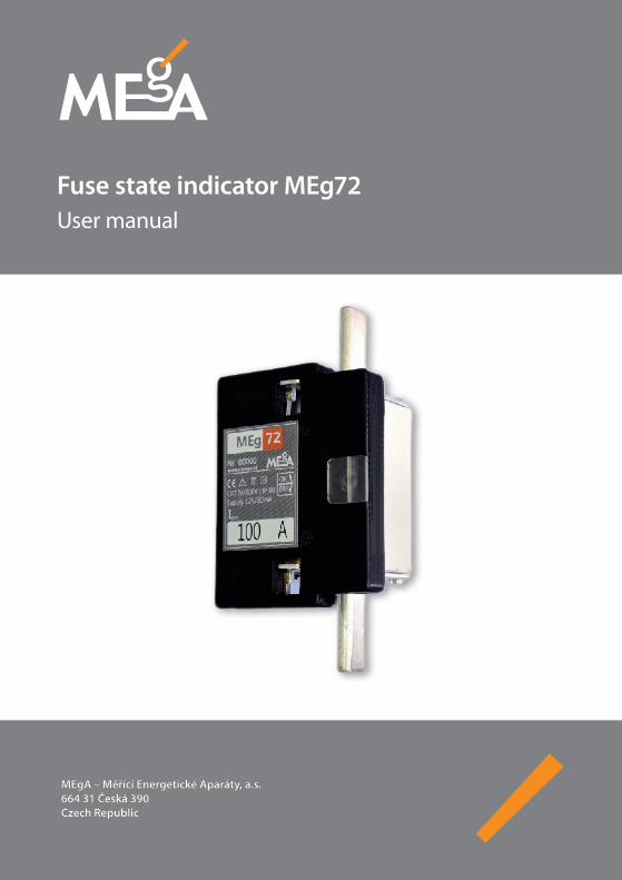
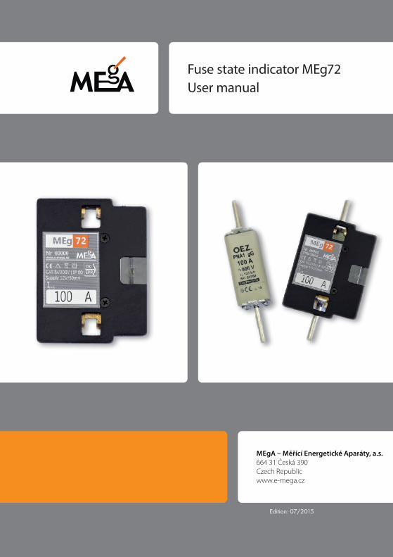
Fuse state indicator MEg72User manual

Fuse state indicator MEg72 – User manual
3
Fuse state indicator MEg72
INTRODUCTION
The fuse state indicator MEg72 is used for local and remote indication of the knife-blade-contact fuse in LV grids. It enables identification of the states of fuses also in parallel power supplied LV networks, LV mesh networks or in LV networks with distributed generation. The state of the fuse is represented by a two-coloured LED, the state of a gal-vanically separated contact of a polarized relay and for remote connection the indicators are equipped with a RS485 interface with a MODBUS protocol.
The indicator consists of a plastic body with slide-in contacts. Side contacts are screwed to the plastic housing for side mounting to a load-break switch rail. The indicator houses a covered terminal board for connecting cables.
The MEg72 indicator meets the requirements of overvoltage category CAT IV / 300 V; it can be installed in all points of LV networks, including distribution transformer substa-tions.
FUNCTION DEsCRIpTION
The MEg72 fuse state indicator measures the voltage in front and behind the fuse and statistically evaluates their difference, based on which it will determine the state of the fuse on which it is installed. The power supply of indicator requires of 12 VDC. The good or unbroken / faulty state of the fuse can be seen on the two-coloured OK/ERR LED, it is also signalized by the galvanic free contact of the polarized relay and it is remotely transferred using a RS485 interface with MODBUS protocol.
After connection to power supply the LED changes from green light to red, until the state of the fuse is evaluated. In case that the voltages on both sides of the fuse are insuf-ficient for evaluation, LED continues to change from green to red. The unbroken fuse is indicated with a short repeated pulse of the green LED for 2 sec, the broken fuse is indicated with a shortly interrupted continuous light of the red LED for 2 sec. The short
Měřící Energetické Aparáty
4
interruptions of LED light also inform the operator that the processor is functioning correctly. After installation of new fuse, the transition of the red interrupted light to the green interrupted light has a delay of approx. 30 sec. If the voltages on both ends of the fuse drop under 60 % Un, the short interruptions of the green or red light is prolonged and duty cycle of the light has a frequency of 1:1. In case that 12 VDC is not available, the LED is switch off. Other LED lights combination of signalling means an error of the MEg72 indicator.
An open contact of relay signalizes an unbroken fuse and closed relay contact signalizes an error in the fuse. The relay switches from open to closed with a delay of approx. 2 sec after an error appears in the fuse and the switch from closed to open is delayed by approx. 30 sec after the fuse is reconnected. The state of the polarized relay remains the same in case its power supply is interrupted. In case when the state of the fuse changes during the time the power supply is interrupted, the contact of the polarized relay is set to the corresponding state after its power supply has been renewed and the state of the fuse has been evaluated.
When communicating via MODBUS and with a connected power supply the following states of the fuse indicator are used:
– unbroken fuse; – the state of the fuse cannot be evaluated (both measure voltages are below
60 % Un), the last evaluated state was unbroken fuse; – faulty fuse; – the state of the fuse cannot be evaluated (both measure voltages are below
60 % Un), the last evaluated state was faulty fuse; – the state of the fuse is being evaluated after its replacement, this takes approx.
1.5 minutes; – the state of the fuse is being evaluated after the power supply has been recon-
nected, it takes approx. 30 sec; – the change of the state of a fuse from unbroken to faulty or vice versa, this transi-
tive state is signalized until the first reading of the fuse state.
Fuse state indicator MEg72 – User manual
5
TEChNICal paRaMETERs
The MEg72 fuse state indicator may be used in TN networks.
The MEg72 fuse state indicator is designed for PN or PNA types of knife-blade-contact fuses with ratings 1(01), 1, 2(02), 2, 3(03) and 3.
Nominal voltage Un: 230 V
Nominal frequency fn: 50 Hz
Indication range: 60 % Un to 120 % Un (at least one voltage)
Rated voltage of power supply: 12 VDC
Rated current of power supply: 30 mADC
Range of supply voltage: 9 VDC to 15 VDC
Galvanically isolated communication: RS485
Communication protocol: MODBUS
default settings: 115.2 kbit/sec, 8 bit, no parity, one stop bit
Maximum voltage on relay contacts: 30 VDC, 30 VAC
Relay contact maximum current: 1 A
Diameter of conductor in spring terminals: 0.2 mm2 to 0.75 mm2
Maximum diameter of the power supply and communication cable: 5.0 mm
Unit dimensions: 84 × 63 × 10.5 mm
Unit dimensions with side contacts: 84 × 63 × 49 mm
Operation temperature range: -25 °C to +55 °C
Storage temperature range: -40 °C to +70 °C
Average relative humidity within 24 hours: up to 95 %
Protection rating: IP00 (placement on LV fuses)
Overvoltage category: CAT IV / 300 V
EMC: EN 61326-1:2013
Měřící Energetické Aparáty
6
DEsIgN aND CONNECTION
Operation, processing and communication circuits of the MEg72 indicator are located in a plastic housing filled with an impregnation substance, which ensures a long-term oper-ating life of the indicator even in challenging LV environments in fuse boxes. The surface of the created compact unit is insulated.
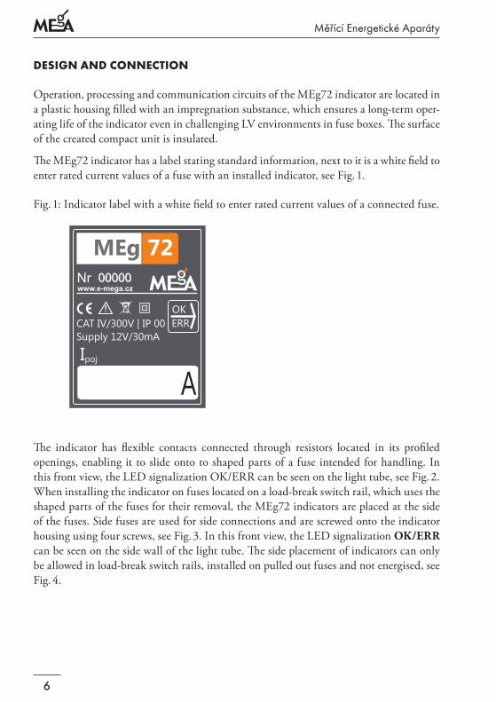
The MEg72 indicator has a label stating standard information, next to it is a white field to enter rated current values of a fuse with an installed indicator, see Fig. 1.
Fig. 1: Indicator label with a white field to enter rated current values of a connected fuse.
OK
ERR
72
www.e-mega.cz
Supply 12V/30mA
CAT IV/300V | IP 00
00000
Ipoj
A
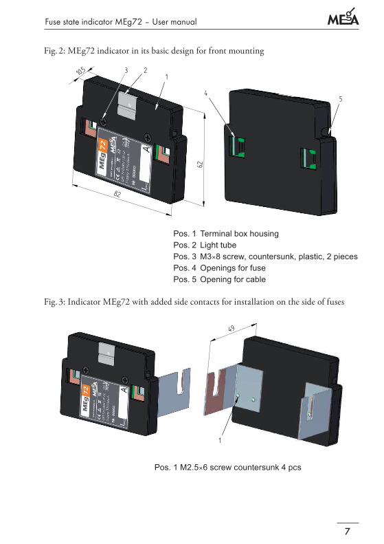
The indicator has flexible contacts connected through resistors located in its profiled openings, enabling it to slide onto to shaped parts of a fuse intended for handling. In this front view, the LED signalization OK/ERR can be seen on the light tube, see Fig. 2. When installing the indicator on fuses located on a load-break switch rail, which uses the shaped parts of the fuses for their removal, the MEg72 indicators are placed at the side of the fuses. Side fuses are used for side connections and are screwed onto the indicator housing using four screws, see Fig. 3. In this front view, the LED signalization OK/ERR can be seen on the side wall of the light tube. The side placement of indicators can only be allowed in load-break switch rails, installed on pulled out fuses and not energised, see Fig. 4.
Fuse state indicator MEg72 – User manual
7
Fig. 2: MEg72 indicator in its basic design for front mounting
49
10,5
8262
12
3
54
1
obr.3
obr.2
Pos.1 TerminalboxhousingPos.2 LighttubePos.3M3×8screw,countersunk,plastic,2piecesPos.4OpeningsforfusePos.5Openingforcable
Fig. 3: Indicator MEg72 with added side contacts for installation on the side of fuses
49
10,5
82
62
12
3
54
1
obr.3
obr.2
Pos.1M2.5×6screwcountersunk4pcs

Měřící Energetické Aparáty
8
Fig. 4: Installation of MEg72 indicator onto fuses in a load-break switch rail
5 4
3 6
2
1
Pos. 1 Swing-outpartofload-breakswitchrailwithfusesPos. 2 Corepartofload-breakswitchrailPos. 3 PlacementofcablesaroundswivelPos. 4 Slidingindicatorontoknife-bladecontactsPos. 5 TopowersourceandcommunicationunitPos. 6 Orientationofsidelighttube
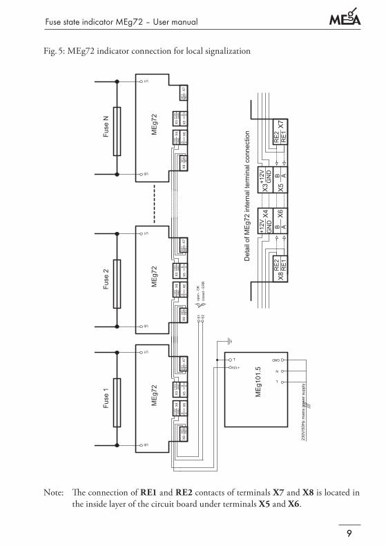
The MEg72 has a covered terminal strip with spring terminals for connecting the power supply voltage, remote control and local signalization, see. Fig. 5. It also shows the in-stallation of several MEg72 indicators on fuses. The +12 V power supply voltage and a common conductor of the power supply voltage and the voltage measuring circuit are connected to terminal X4 which is connected to terminal X3 in the indicator, the power supply is then connected to the neighbouring indicators. A MEg101.5 power source, overvoltage category CAT IV can be used with supercapacitors to provide a power supply even during short-term interruptions of the power supply from the mains.
Voltage on fuse contacts is done against a mutual GND conductor, which must be grounded! The power source must have its output voltage galvanically free or it
must be grounded on a negative pole. The contact of the polarized signalization relay of the indicator with RE1 and RE2 poles is attached to connected terminals X7 and X8. Connecting the indicator contacts, see Fig. 5, the fault of any of the fuses is signalized by connecting output terminals S1 and S2.
Fuse state indicator MEg72 – User manual
9
Fig. 5: MEg72 indicator connection for local signalization
ME
g101
.5
230V
/50H
z m
ains
pow
er s
uppl
y
ME
g72
Fuse
1U0
U1
RE
2R
E1
+12V
GN
D
X8X7
RE
2R
E1
+12V
GN
D
ABB A
X6X4X3 X5
U0
U1
RE
2R
E1
+12V
GN
D
X8X7
RE
2R
E1
+12V
GN
D
ABB A
X6X4X3 X5
ME
g72
Fuse
2
U0
U1
RE
2R
E1
+12V
GN
D
X8X7
RE
2R
E1
+12V
GN
D
ABB A
X6X4X3 X5
ME
g72
Fuse
N
X8
X4
X6
X3
X5
X7
RE
2R
E1
RE
2R
E1
+12V
GN
D+1
2VG
ND
B AB A
Det
ail o
f ME
g72
inte
rnal
term
inal
con
nect
ion
S1
S2
open
- O
Kcl
osed
- E
RR
T GND
N+12V
L
Note: The connection of RE1 and RE2 contacts of terminals X7 and X8 is located in the inside layer of the circuit board under terminals X5 and X6.
Měřící Energetické Aparáty
10
Fig. 6: MEg72 indicator connection for remote communication
U0
U1
RE
2R
E1
+12V
GN
D
X8X7
RE
2R
E1
+12V
GN
D
ABB A
X6X4X3 X5
U0
U1
RE
2R
E1
+12V
GN
D
X8X7
RE
2R
E1
+12V
GN
D
ABB A
X6X4X3 X5
ME
g72
Fuse
2
U0
U1
RE
2R
E1
+12V
GN
D
X8X7
RE
2R
E1
+12V
GN
D
ABB A
X6X4X3 X5
ME
g72
Fuse
N
ANTE
NN
AM
Eg1
01.4
T1
2T
ME
g202
.3
ME
g72
Fuse
1
230V
/50H
z m
ains
pow
er s
uppl
y
AKU
OUT11
OUT21
+12V
IN1
B1
IN5
B2
GND
OUT22
+
AKU
L
A2
+
T
+12V2
+12V1
T
IN4
+12V
IN3
IN2
N
A1
OUT12
- STOP

Fuse state indicator MEg72 – User manual
11
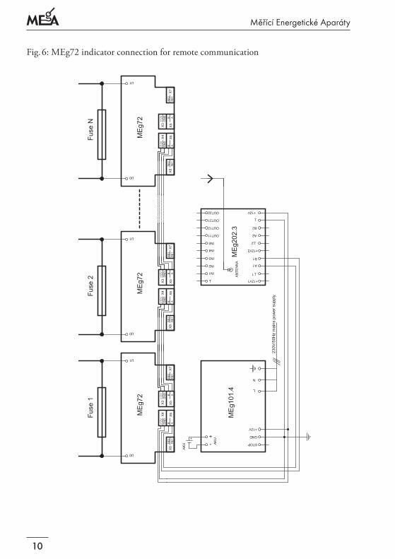
In case of remote communication of the MEg72 indicator, see Fig. 6, e.g. a MEg101.4 secure power source (overvoltage category CAT IV) with a 12 V external accumulator is used. This power supply supplies power to the MEg72 indicators and to the MEg202.3 GSM communication unit with GPRS data transfer. This ensures that even without a mains power supply, the remote transfer of information regarding fuse states is not interrupted. The serial communication interface RS485 of individual MEg72 indicators with A and B contacts is connected to the mutual terminals X5 and X6. The MODBUS protocol ensures the communication between individual indicators and detects the state of individual fuses and indicators.
MEg72 INDICaTOR INsTallaTION
The MEg72 fuse state indicators can be installed on knife-blade fuses in cabinets with classic fuse bottoms, in cabinets with fuse rails and even in cabinets with load-break switch rails.
We further on differentiate between installations with LED indications, local signaliza-tion and remote communication of fuse states.
1. Individual cable lengths are selected depending on the distance between the centres of the fuses, this enables shifting the indicator away, not needing to disassemble it, when a fuse needs replacement. Note 1)
2. Cables are on both ends, in a length of approx. 25 mm, opened and in case of wires, crimp terminals with a diameter of 0.25 mm2 with a length of 7 to 9 mm are used.
3. Depending on the fuses stacked next to each other, the rated current values of the fuses are permanently written (permanent marker) into the white field of a relevant indicator.
4. After unscrewing the screws, the covers of the terminal strips are removed.
5. The +12 V power supply conductor and the mutual GND of the input and output cable are connected to the spring terminals X3 and X4, see Fig. 5.
Note 1: It is necessary to use a cable with a maximum diameter of 5.00 mm and insula-tion suitable for installation into a LV cabinet, when installing an indicator. The diameter of a conductor that can be inserted into a spring terminal is 0.22 mm2 to 0.75 mm2. The indicator manufacturer uses a TBVFS 4 × 0.22 cable, which stays flexible during tem-peratures below zero, with a testing voltage of 5.4 kV (CAT IV) and four wire conduc-tors, which are equipped with crimp terminals enabling connection into indicator spring terminals.
Měřící Energetické Aparáty
12
6. Two more cable conductors are installed depending on the type of connection.
They are inserted in to terminals X7 and X8 for local signalization, see Fig. 5.
They are inserted in to terminals X5 and X6 for remote communication, see Fig. 6.
If it is necessary, the MEg72 indicator can also be used for local signalization as well as for remote communication. It is necessary to use a cable with six conduc-tors.
7. The terminal strips with connected input and output cables are covered with covers with light tubes, which will properly secure the cable against accidental removal once tightly screwed in.
8. The power supply conductors (+12 V, GND) of the first cable of the indicators con-nected behind each other must be connected to a switched off 12 VDC power supply. Signalization or communication conductors must be connected to terminals of the signalization unit or the communication unit, see Fig. 5 or Fig. 6.
9. Using all safety measures necessary for work with live wires as well as with personal safety items, interconnected indicators are mounted onto the fuses.
a) Installation of indicators in fuse cabinets with classic fuse bottoms and in cabi-nets with fuse rails is done by sliding the indicator onto the profiled part of the fuse.
b) Before mounting indicators onto the side of fuses in a cabinet with load-break switch rails, each indicator must be equipped with a screw-on slide contact, in order for the indicator to slide onto the fuse from the bottom, so it is possible to see, from the top, the side of the light tube LED status OK/ERR. The indicators are installed onto fuses located in the cover of the load-break switch rail. Con-necting cables between individual indicators are installed between sections in the area of the swivel, see Fig. 4. The cover of the load-break switch rail with fuses and installed indicators is returned to its working position.
10. The 12 V power supply is switched on. The LEDs OK/ERR will first light up and rapidly change from red to green and after approx. 30 seconds, it will change to a green, shortly interrupted, light.
11. If all fuses are OK and a local signalization option has been chosen, contacts S1 and S2 remain disconnected.
12. The communication of the MEg72 indicators can be verified using a PC with a RS485 interface and a MERCI communication program or a program that is able to work with MODBUS instructions.
Fuse state indicator MEg72 – User manual
13
REMOvINg ThE MEg72 INDICaTOR
The indicator may only be removed by qualified persons using safety equipment for working with live devices and persons with protective and work equipment and tools.
A. Replacing a fuse in a classic fuse bottom or fuse rail
1. The MEg72 indicator installed on a knife-blade fuse located in a classic fuse bottom or fuse rail is removed from the fuse. It will remain connected to the input and output cable.
2. The indicator is pulled aside the knife-blade fuse and the fuse is replaced. When replacing a fuse with a new fuse with a different rated current value, such new value must be entered into the white field on the indicator label.
3. Using personal protective and work equipment and tools a qualified person will slide the MEg72 indicator onto the profiled part of the fuse.
B. Replacing fuses in the load-break switch rail
1. Opened cover of the load-break switch rail with connected fuses and installed MEg72 indicators.
2. Removal of indicator from knife-blade contacts of a replaced fuse. When replacing a fuse with a new fuse with a different rated current value, such new value must be entered into the white field on the indicator label.
3. Sliding an indicator onto the knife-blade contacts of a newly installed fuse in the load-break switch rail.
4. Placement of connection cables into the area around the swivels and returning the load-break switch rail cover into its operation position.
C. Exchanging a faulty indicator
1. Switch off the 12 V direct current power supply.
2. Using personal protective equipment, remove defect indicator or several neighbouring indicators, if necessary, from the fuses and place the defect in-dicator into an area outside of the dangerous voltage area.
3. Disassemble the cover with the light tube of the defect indicator as well as of the new indicator.
4. Using a narrow screwdriver or loosening fixture, remove the conductors of the input and output cable from the terminals of the defect indicator.

Měřící Energetické Aparáty
14
5. Connect the conductors of the input and output cable into the correct terminals of the new indicator.
6. Properly tighten cover with light tube of the new indicator and verify the strength of the mechanical connection of the input and output cable.
7. Install the new indicator, or the neighbouring indicators, if removed, in the manner described above back onto the correct fuse.
8. The defect MEg72 indicator must be disposed of according to local rules for electri-cal waste disposal, after its warranty expires. Defect indicators with a valid warranty are subject to conditions described in the article Warranty.
MODBUs pROTOCOl INsTRUCTION OF MEg72 INDICaTORs
The MODBUS protocol used in MEg72 indicators is described in detail in the MODBUS protocol implementation in MEgA, devices, see www.e-mega.cz.
The MEg72 uses these MODBUS functions:0x03 – reading and preserving registers0x04 – reading MEg72 input registers0x06 – entry into preserved registers
Addresses of preserved registers
4 Device address5 Baudrate/100 6 Parity7 MODBUS MEgA version
Address of MEg72 input registers
0 Device Type = 721 Firmware version2 Serial number3 Serial number group (expansion)50 Status word of fuse
Fuse state indicator MEg72 – User manual
15
The state word of a fuse is represented by a bit structure that besides informing about the state of the fuse, also describes the evaluation status. The bits in the status word have the following meaning:
D0 1 = Unbroken fuse
D1 1 = Previous status unbroken fuse – internal status, where due to an interruption of power supply, it is not possible to evaluate the immediate status.
D2 1 = Faulty fuse
D3 1 = Previous status faulty fuse – internal status, where due to an interruption of power supply, it is not possible to evaluate the immediate status.
D4 1 = Undefined status after switching on the MEg72 power supply and there is no voltage on the fuse.
D5 1 = Probably unbroken fuse – internal status, when a defect fuse, based on a pro-tection element against entering an unbroken fuse state, the fuse enters an approx. 70 second monitoring period. If the fuse is evaluated as unbroken fuse during the entire monitoring period, it is switched to an unbroken fuse state, after the monitoring period ends.
D6 not used
D7 1 = Change. Signalization of a fuse status change from unbroken fuse to faulty fuse and vice versa. The bit is automatically cancelled after reading the status word. This makes it possible for superior systems to easily monitor status changes.
Měřící Energetické Aparáty
16
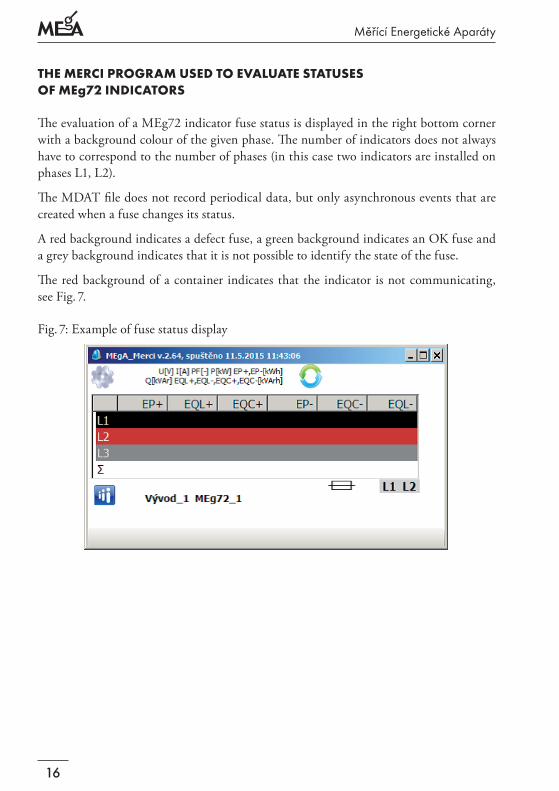
ThE MERCI pROgRaM UsED TO EvalUaTE sTaTUsEs OF MEg72 INDICaTORs
The evaluation of a MEg72 indicator fuse status is displayed in the right bottom corner with a background colour of the given phase. The number of indicators does not always have to correspond to the number of phases (in this case two indicators are installed on phases L1, L2).
The MDAT file does not record periodical data, but only asynchronous events that are created when a fuse changes its status.
A red background indicates a defect fuse, a green background indicates an OK fuse and a grey background indicates that it is not possible to identify the state of the fuse.
The red background of a container indicates that the indicator is not communicating, see Fig. 7.
Fig. 7: Example of fuse status display
Fuse state indicator MEg72 – User manual
17
lIsT OF MEg72 INDICaTOR COMpONENTs
1 pc MEg72 indicator
2 pcs of side, slide-on contacts with 4 pcs of screws with cheese head M2,5×4 mm
1 pc warranty certificate with final inspection record
1 pc CD with description and SW for communication with MEg72 indicator
Optional
N m of four-core cable TBVFS 4×0,22
N pc MEg101.5 power supply in CAT IV / 300 V overvoltage category, www.e-mega.cz
N pc of secure power supply MEg101.4 CAT IV / 300 V, www.e-mega.cz
N pc MEg202.3 communication units, www.e-mega.cz
N pc Ethernet MEg201.2 communication units, www.e-mega.cz
N pc RS485/USB converters
ORDERINg DaTa
Number of indicators MEg72 with accessories
Number of MEg101.5 power supply in CAT IV / 300 V overvoltage category
Number of MEg101.4 secure power supply CAT IV / 300 V
Number of MEg202.3 communication units
Měřící Energetické Aparáty
18
WaRRaNTy
The MEg72 is covered by a 24-month warranty from the date of purchase, however not longer than 30 months from the date of release from the manufacturer's warehouse. Defects originating during this period as a demonstrable result of defective design, manu-facturing or using improper material will be repaired free of charge by the manufacturer or his service organization.
The warranty becomes invalid if the user carries out unauthorized modifications or changes on the indicator or on its accessories if he connects the instrument incorrectly or if the indicator or its accessories were operated contrary to technical conditions and user description.
The defects on the indicator and its accessories originated during the warranty period shall be claimed by the user to the manufacturer or to the service organization authorized by the manufacturer.
The manufacturer bears in any case no responsibility for subsequent
damages caused by using the MEg72 indicator and its accessories.
The liability of the manufacturer, based on this warranty, does not exceed the price of the indicator.
MaNUFaCTURER
MEgA – Měřící Energetické Aparáty, a.s.
664 31 Česká 390, Czech Republic
Tel. +420 545 214 988
e-mail: [email protected]
web: www.e-mega.cz

MEgA – Měřící Energetické Aparáty, a.s.664 31 Česká 390Czech Republicwww.e-mega.cz
Edition: 07/2015
Fuse state indicator MEg72User manual


![The Analytic Torsion of Manifolds with Boundary and ...hss.ulb.uni-bonn.de/2008/1494/1494.pdf · duced by K. Reidemeister in [Re1, Re2] and generalized to higher dimensions by W](https://img.pdfslide.us/doc/110x75/5edc7c12ad6a402d6667290a/the-analytic-torsion-of-manifolds-with-boundary-and-hssulbuni-bonnde200814941494pdf.jpg)