Embed Size (px)
Citation preview

The Strength of 3D Printing
By: Samuel Deal

Additive Manufacturing
• Adds material to build up a structure rather than removing it
as waste.
• Effective for its ease of use, fast prototyping, flexibility, and
lack of waste
• Struggles because of limited materials, slow production
speeds, and relatively low precision

The MarkForged Mark OneSolidWorks Eiger
Printer

As Strong As Aluminum?
• The Mark One has the capability to reinforce its nylon prints
with structural fibers like fiberglass, kevlar, and carbon fiber.
• Claims to make the strength of the printed parts rival that of
aluminum
• My research has been to test the claims.

SolidWorks Simulation• Finite Element Analysis
(FEA) breaks down
solid objects into small
pieces with a “mesh”
Software balances the relevant conditions for each vertex of the elements

SolidWorks Simulation
• Learned to use the
static simulation
tools
• Set up a basic load
test for a solid
aluminum square
beam
Stress
Displacement

• First modeled the core of the printed part as pattern of triangles• Slow rebuild times, edits
take too long to load
Tried approximating the triangles as circles to improve the speedReduced edges by 77% and faces by 66%Improvement but still fairly slow
Creating the 3D Printed Model

• Model the honeycomb
core of the print as a
new material
• Orthotropic materials
have different
properties in the
different coordinate
directions
• Ex: wood, fiberglass,
carbon fiber. Max
strength along the
length of the fibers
Orthotropic Material

• Creating a core with the
new material sandwiched
between layers of fiber:
• The boundary condition
between the layers was
defined as bonded
• The same load condition as
the aluminum beam was
applied to this model
Simulating the Model
Results Plots Stress Plot
Displacement Plot
FOS Plot
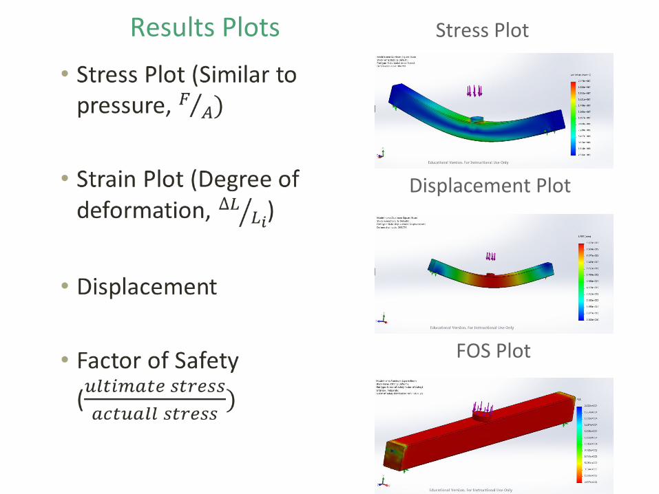
• Two-point beam stiffness
test
• Hydraulic cylinder
applies force, load cell
reads out force, indicator
measures displacement
Testing the Printed Beam

• Plot Force vs. Displacement data
Elastic deformation leads to linear relationship

Conclusion
• The fiber reinforced plastic (FRP) has impressive strength
• Aluminum according to the simulation is much stiffer than the
fiberglass FRP
• The FRP however may be able to handle a similar weight
before complete failure.

3D Printing a Pump
Paul Helgemo

3D printing
● Decreases time to prototype
● Mark One ○ Strong/working
parts○ Can reinforced
nylon with Fiberglass, Kevlar, and Carbon-Fiber
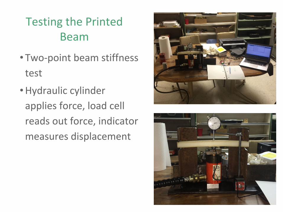
Pumps
● Mechanical and Chemical Engineering meet
● How do we effectively and efficiently move liquids?
● 2000 BC Egypt and the shadoof
● 1851 John Appold invented the centrifugal pump
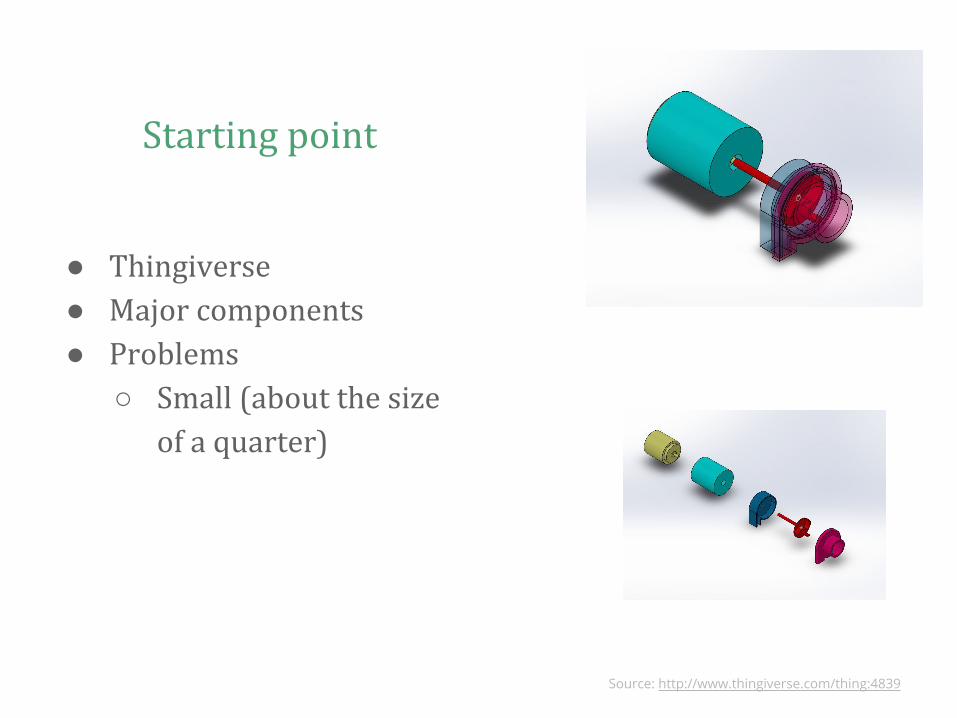
Starting point
● Thingiverse● Major components● Problems
○ Small (about the size of a quarter)
Source: http://www.thingiverse.com/thing:4839

Final Design

Unit Value
Mass Flow Rate Inlet [kg/s] 0.0361
SG Mass Flow Rate Outlet
[kg/s] -0.0361
Pressure Drop [Pa] 56.9
Simulation Data
● Mass is conserved
○ “Watertight”
● Difference in Pressure

Build Notes● Problems printing
Top shell○ Support
material○ Kevlar
reinforcement

Head Height
● How high can the pump push a liquid against gravity● A simple measure of performance● Higher the head = more powerful the pump

Test Notes
● Trial 1 ○ Head height 23 cm
● Trial 2○ Head height 10 cm
● Trial 3○ Head height 15 cm
● Problems○ Troubleshooting○ Impeller speed
control○ Motor damage○ My lack of experience

Next Step
● Increase sample size● More thought on holding tanks● Use fiberglass ● Find better ways to seal

3D Printing a Quadcopter
Christian Griffin

Presentation Outline
• Use SolidWorks and the 3D printer to design and
produce the frame of a quadcopter.
• Build a functioning 250 class quadcopter with the printed
frame.
– Note: 250 is the distance from motor center to motor
center along a diagonal, in millimeters.

Crucial Components
• Flight Controller
– Automatically
Stabilizes Flight.
• Motor Controllers
– Adjust speed of
motors.
• Together they are
responsible for
producing all the
possible movements.

More Components• Motors • Propellers • Transmitter and
Receiver
• Battery • Frame

Initial Goals
• Print the entire frame in one piece for added strength.
• Save weight.
• Reinforce the Nylon with Carbon Fiber.
• Mount a camera for aerial photography.
• Frame should look aggressive and fast.

Some Initial Designs

Early learning curve
• Initially was attempting to design and print
in one piece.
• This goal was being hampered by the size
of the print bed.
• Print size is:
– 320mm X 132mm in
the plane of the bed.
– 154mm vertically.

Design Process
• Realized the print bed was constraining the size too
much.
• Thought about printing it in two pieces.

Design Process
• Decided against printing it in two pieces:
– Would have been very hard to print a fastening
system that would be strong.
– The place of connection would be right by all of the
electronics.
• Decided to print in six pieces:
– Two base plates
– Four arms.

Other Printing considerations
• The mark one prints layer on top of layer.
• Thus overhanging structures require support material.
• With numerous things such as ribs in an arm this can
become a huge nuisance.
• Decided to avoid support material by designing with
method of printing in mind.

How the Mark One prints Fiber
• Fill types for fiber:
– Isotropic
– Full
– Concentric

Troubleshooting my Arm
• The only fill type available for Carbon Fiber is concentric
• The shape of the arm was not working for concentric fill
• This forced me to choose Kevlar instead
• Initially my arm was 5mm thick
• After printing with Kevlar it was too flexible

Final Arm Design

Final Base Plate Designs
Top Base Bottom Base

Final Assembly

Things to Come
• Camera
• Cover for flight controller
• Fiber reinforced landing gears

Improvements
• Cut weight wherever possible
• Better battery
• Smaller motor controllers
• Implement wire control in design

Acknowledgements
• Thank you:
- Bob Czerniewski and
Mascaro Construction
-FISH
-Dr. Greenly
-Dcn. Lopus
-Office of Academic Affairs
-Dr. Kempton