Embed Size (px)
Citation preview

Accepted Manuscript
Title: Further study of the hydrogen embrittlement ofmartensitic advanced high strength steel in simulated autoservice conditions
Authors: Jeffrey Venezuela, Jethro Blanch, Azmir Zulkiply,Qinglong Liu, Qingjun Zhou, Mingxing Zhang, Andrej Atrens
PII: S0010-938X(17)30065-3DOI: https://doi.org/10.1016/j.corsci.2018.02.037Reference: CS 7394
To appear in:
Received date: 13-1-2017Revised date: 8-2-2018Accepted date: 19-2-2018
Please cite this article as: Jeffrey Venezuela, Jethro Blanch, Azmir Zulkiply, QinglongLiu, Qingjun Zhou, Mingxing Zhang, Andrej Atrens, Further study of the hydrogenembrittlement of martensitic advanced high strength steel in simulated auto serviceconditions, Corrosion Science https://doi.org/10.1016/j.corsci.2018.02.037
This is a PDF file of an unedited manuscript that has been accepted for publication.As a service to our customers we are providing this early version of the manuscript.The manuscript will undergo copyediting, typesetting, and review of the resulting proofbefore it is published in its final form. Please note that during the production processerrors may be discovered which could affect the content, and all legal disclaimers thatapply to the journal pertain.

Final.docx Page 1 of 51
Further study of the hydrogen embrittlement of martensitic advanced high strength steel in
simulated auto service conditions
Jeffrey Venezuelaa, Jethro Blancha, Azmir Zulkiplya, Qinglong Liua, Qingjun Zhoub,*,
Mingxing Zhanga, Andrej Atrensa,*
a The University of Queensland, Division of Materials, School of Mining and Mechanical
Engineering, St. Lucia, 4072 Australia * Corresponding author, [email protected], +61 7 3365 3748,
[email protected], +86 21 26641807 b Baoshan Iron & Steel Co., Ltd, Research Institute, Shanghai, 201900,China
Highlights
Susceptibility increased at increasingly negative potentials and at lower pH in 3.5%
NaCl
Susceptibility increased at high charging potentials in 0.1 M NaOH at substantial
stress rates.
The hydrogen influence was manifested by reduced ductility and brittle fracture
features
ABSTRACT
This work examines the influence of hydrogen on the mechanical and fracture properties of
martensitic advanced high-strength steels under conditions relevant to automotive service: (i)
in 3.5 wt% NaCl at different cathodic potentials, (ii) in acidified 3.5 wt% NaCl and (iii) at
substantial stress rates. The hydrogen embrittlement susceptibility of the steels increases at (i)
increasingly negative potentials and at lower pH in 3.5 wt% NaCl, and (ii) at high charging
potentials in 0.1 M NaOH at substantial stress rates. The hydrogen influence is manifested by
a reduction in ductility, and the presence of brittle features on the fracture surface.
Keywords: A. steel; B. SEM; C. hydrogen embrittlement
ACCEPTED MANUSCRIP
T

Final.docx Page 2 of 51
1. Introduction
Martensitic advanced high-strength steels (MS-AHSS) are attracting attention for the
manufacture of lightweight, crashworthy cars [1-3]. MS-AHSS have good strengths, ranging
950 to 1700 MPa, are inexpensive to manufacture, but exhibit limited ductility and
formability [4, 5]. MS-AHSS are used to make automotive body-in-white (BIW) components
such as (i) bumper beams and reinforcements, (ii) door intrusion beams and reinforcements,
(iii) windscreen upright reinforcements, and (iv) B-pillar reinforcements [1, 6-8].
Hydrogen embrittlement (HE) occurs in steels, such as in conventional high-strength
steels [9-24], advanced high-strength steels [25-39], and medium-strength steels [40-49]. HE
occurs when the load-bearing steel interacts with a critical amount of hydrogen. HE can result
in (i) a reduction of mechanical strength, toughness and ductility, together with (ii) subcritical
crack growth [50, 51]. Alternatively, HE can cause some reduction of ductility without an
appreciable decrease in yield and tensile strength [52], and without sub-critical crack growth.
Automotive steels may be subject to corrosion in automobile service. A marine
environment is a common environment that causes aggressive corrosion of steels in the auto
body [53]. Similar aggressive corrosion occurs for auto bodies due to de-icing salts used in
snowy climates. Hydrogen may be produced by the corrosion, may diffuse into the stress-
bearing steel auto component, and could conceivably cause hydrogen delayed fractures [54].
During accidents, car components are subjected to impact stresses at high-applied
stress rates. Adequate toughness in automotive steels is needed so that the component fails by
a ductile mode rather than fractures. Any factor that could lower the toughness of an
automotive structure, such as hydrogen, requires to be understood by car manufacturers.
This current research builds on our previous study, which studied the HE
susceptibility of automotive MS-AHSS in simulated service conditions, using the linearly
increasing stress test (LIST) and conventional tensile tests [27]. The LIST [55] has been
widely used to study hydrogen embrittlement (HE) and stress corrosion cracking (SCC) [9,
10, 14, 42, 56-62]. Our previous work [27] studied four grades of MS-AHSS using LIST at
the open circuit potential, Ecorr, and at the zinc potential, EZn, equivalent to -950 mVAg/AgCl (-
752 mVSHE), in 3.5% NaCl and at different stress rates. There was minimal HE susceptibility
in these MS-AHSS at both Ecorr and EZn, and at all stress rates; partly due to the low hydrogen
concentrations under these hydrogen-charging conditions.
However, it is possible that HE in these steels could occur at higher cathodic
potentials where a greater hydrogen fugacity is expected [63]. In addition, it is known that the
ACCEPTED MANUSCRIP
T

Final.docx Page 3 of 51
hydrogen equilibrium potential decreases with decreasing pH [64], so that there is more
hydrogen evolution during corrosion in acidic solutions. This means that a decrease in pH can
increase the corrosion rate of steels [53], and would also increase the amount of hydrogen
produced during corrosion. Also, the presence of NaCl would further add to the
aggressiveness of corrosion in acidic solutions.
Acidified NaCl solutions occur during crevice corrosion and pitting corrosion. The pH
can decrease to below pH 2 inside a crevice and a corroding pit, in a NaCl solution [65]. Thus
tests on steels immersed in acidified 3.5% NaCl are relevant to understand the sensitivity of
MS-AHSS to the conditions present in crevice corrosion and pitting corrosion.
In each case, as in our prior research [25, 27, 39], cathodic pre-charging was carried
out for 24 h before the commencement of any testing to ensure that (i) there was a stable
surface condition at the charging surface, and (ii) the hydrogen concentration was uniform
throughout the specimen. Our prior research using permeation experiments [27-29, 36],
indicated that long-term hydrogen pre-charging was required to ensure the reduction of the
initial surface oxides to a steady state condition, for which the permeation current density was
stable. Furthermore, modelling of the hydrogen concentration using the diffusion coefficients
measured in the permeation experiments indicated that the hydrogen concentration was a
constant throughout the specimens used for these long term charging conditions [27-29, 36].
Our previous study used tensile tests to study the influence of a substantial-applied
stress rate on the HE susceptibility of MS-AHSS under conditions of internal hydrogen
embrittlement (IHE) [27]. IHE refers to HE in the absence of hydrogen charging [66]. The
hydrogen is already inside the steel, i.e. the hydrogen may have entered the steel during the
processing or fabrication steps or during previous service corrosion. IHE was evaluated by
mechanical tests on specimens in the absence of hydrogen charging [27]. Smooth tensile
specimens were hydrogen charged in tension in the LIST apparatus, dismounted, and then
subjected to a tensile test using a universal testing machine (UTM) within a short time after
the end of hydrogen charging. The results did show negligible hydrogen influence on the
mechanical properties of MS-AHSS, even though modelling indicated that most of the
hydrogen remained in the steel.
In contrast, external hydrogen embrittlement (EHE), also known as hydrogen
environment embrittlement (HEE), results from exposure to a hydrogen-bearing environment
[67]. For hydrogen gas, hydrogen is believed to enter the metal via the surface adsorption of
diatomic hydrogen, followed by absorption in the lattice after dissociation into the
ACCEPTED MANUSCRIP
T

Final.docx Page 4 of 51
monoatomic form. EHE is evaluated by mechanical tests in the presence of a hydrogen
environment.
Past research has noted several similarities and differences between IHE and EHE
[68]. Both processes need a critical level of stress and a critical hydrogen concentration. It is
possible that the MS-AHSS may behave differently when evaluated under EHE conditions.
The present paper adds to the knowledge of the relevance of the HE to MS-AHSS in
automobile service. The specific issues addressed by this work were as follows:
1. the HE susceptibility of MS-AHSS in 3.5wt% NaCl at -950 mVAg/AgCl (-752 mVSHE) and -
1050 mVAg/AgCl (-852 mVSHE), and the measurement of the hydrogen concentrations in
the steels at these potentials,
2. the HE susceptibility of MS-AHSS in pH-modified 3.5wt% NaCl, to assess the HE
susceptibility of MS-AHSS during pit corrosion or crevice corrosion, and
3. the EHE of MS-AHSS under a substantial loading rate that is relevant to a crash situation.
2. Experimental methods
2.1. Steels, electrolytes, and apparatus
The test materials were four grades of commercial MS-AHSS; namely MS980,
MS1180, MS1300 and MS1500. The steels were from commercial production, and were
supplied as flat rolled sheets with the chemical composition and the mechanical properties as
presented in Table 1. The chemical composition was determined by an independent
laboratory (Spectrometer Services Pty Ltd, Coberg, Vic), whilst the mechanical properties
were provided by the steel supplier. The microstructure of these steels consisted of a
combination of mainly martensite and some ferrite [25], with proportions as listed in Table 1.
The LIST and tensile test specimens were machined using a water jet cutter to the
dimensions shown in Fig 1. The long direction of each specimen was parallel to the rolling
direction. The specimens were mechanically ground using SiC paper (i.e. 320, 600 and 1200
grit), rinsed with ethanol, and blow-dried. The specimen thicknesses were: (i) 1.5 mm for
MS980, (ii) 1.70 mm for MS1180, (iii) 1.20 mm for MS1300, and (iv) 1.18 mm for MS1500. All solutions, i.e. 3.5wt% NaCl, 0.1 M NaOH, and 0.1 M HCl, were prepared using
analytic grade chemicals and deionised water. The pH modifiers were analytic grade (i)
32wt% hydrochloric acid (HCl) and (ii) sodium hydroxide pellets.
ACCEPTED MANUSCRIP
T

Final.docx Page 5 of 51
Electrochemical hydrogen charging used a three-electrode apparatus. The working
electrode was the steel specimen. The reference electrode was either an Ag/AgCl/sat KCl
reference electrode when hydrogen charging in 3.5wt% NaCl, or a Hg/HgO/20wt% KOH
reference electrode when hydrogen charging in 0.1 M NaOH. The counter electrode was
graphite, because our previous work indicated that a graphite electrode was inert with respect
to electrolytic hydrogen charging, whereas a platinum counter electrode caused a smaller
amount of hydrogen to be absorbed by the steel because of the plating of platinum onto the
steel working electrode [27].
The Linearly Increasing Stress Test (LIST) has been described previously [25-27, 55].
The LIST subjects the specimen, exposed to the environment of interest, to a linearly
increasing stress until specimen fracture. The LIST is equivalent to a load controlled slow
strain rate test (SSRT), that is considerably quicker than the SSRT, because specimen fracture
occurs much earlier, e.g. for a specimen in air, fracture occurs at the maximum load when the
specimen becomes mechanically unstable and fractures; and the specimen fractures when the
sub-critical crack reaches a critical size for testing in an environment causing sub-critical
cracking [58]. The tensile strength, F, and yield and threshold stress, TH, were determined
using the potential drop method. The reduction in area, RA, was obtained by measuring the
projected area of the fracture surface. The HE susceptibility index, I, was evaluated as
follows [25]:
𝐼 =𝑅A,air−𝑅A,H
𝑅A,air 100% (1)
where RA,air is the reduction in area in air, and RA,H is the reduction in area in the hydrogen
charging environment. The value of I can range from 0% to 100%, from no HE susceptibility
to maximum HE susceptibility due to the complete absence of plastic strain during failure.
The conventional tensile tests were conducted using an Instron 4505 universal testing
machine (UTM) following the ASTM E-8 standard.
After each mechanical test (i.e. LIST or tensile test), the fractured specimen was
subjected to fracture analysis. At the end of a test that involved electrochemical charging, the
fractured specimen was immediately removed from the charging electrolyte to prevent
corrosion of the fracture surface. The specimen was rinsed in distilled water, blow-dried,
immersed in EDTA solution for 5 minutes, rinsed with ethanol and blow-dried. Each
specimen was cut to an appropriate size using an alumina saw, ultrasonically cleaned in a
4wt% alconox solution for 30 minutes, rinsed in deionized water, and blow-dried. The
ACCEPTED MANUSCRIP
T
Final.docx Page 6 of 51
specimen was mounted on an aluminium stub using a conductive carbon tape, and examined
using a scanning electron microscope (JEOL 6610 SEM).
2.2. LISTs in 3.5wt% NaCl with applied potentials
2.2.1. EZn
Four grades of MS-AHSS (i.e. MS980, MS1180, MS1300 and MS1500) were
studied. The LIST specimen was fixed into the solution chamber and the chamber was
mounted on the LIST apparatus. An initial tensile stress equivalent to 20% of the nominal
yield stress was applied to the specimen. The 3.5wt% NaCl charging solution was poured into
the chamber, the appropriate reference and counter electrodes were inserted, and a cathodic
potential equivalent to EZn (-950 mVHg/HgO (-752 mVSHE)) was applied to the specimen for 24
hours to attain hydrogen saturation throughout the specimen, as verified by our prior
modelling of the hydrogen profile in the specimen [27]. At the end of the charging period, the
LIST commenced. An applied stress rate equivalent to the 3 revolutions/h (rph) motor was
applied on the specimen. The stress rate was determined from the cross-sectional area of the
specimen and the speed of the servomotor used (e.g. 3 or 30 rph motor), and is provided with
the results in the appropriate table.
2.2.2. -1050 mVAg/AgCl
The two strongest grades of MS-AHSS; namely, MS1300 and MS1500, were used in
these tests as these showed the most hydrogen sensitivity [25]. The test procedure was as
described in section 2.2.1, except that (i) the cathodic charging potential applied was -1050
mVAg/AgCl (-852 mVSHE) and (ii) two stress rates were studied corresponding to the 30 (0.08
MPa s-1) and 3 rph (0.008 MPa s-1) motors.
2.3. Permeation tests
The permeation tests were conducted to determine (i) the hydrogen concentrations in
the MS1300 and MS1500 during charging in the 3.5wt% NaCl at the different potentials, and
(ii) the effective hydrogen diffusion coefficients. The tests were performed as described
previously [27] including precharging for 24 h at -1050 mVAg/AgCl in 3.5wt% NaCl. There
were attempts to do charging at potentials more negative than -1050 mVAg/AgCl (-852 mVSHE).
However, beyond -1050 mVAg/AgCl (-852 mVSHE), the toxic gas chlorine was evolved,
probably due to the oxidation of chloride ions at the counter electrode; and thus the tests were
discontinued. The specimen thicknesses were 1.13 mm for MS1300 specimens and 1.09 mm
for MS1500 specimens.
ACCEPTED MANUSCRIP
T
Final.docx Page 7 of 51
The permeation transients were as follows: (i) successive decay transients from -1050
to -950, then -950 to -850 mVAg/AgCl; (ii) successive rise transients from -850 to -950, then -
950 to -1050 mVAg/AgCl; and (iii) full decay from -1050 mVAg/AgCl to the open cell potential.
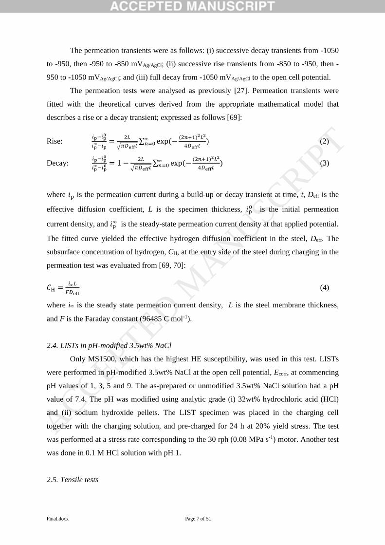
The permeation tests were analysed as previously [27]. Permeation transients were
fitted with the theoretical curves derived from the appropriate mathematical model that
describes a rise or a decay transient; expressed as follows [69]:
Rise: 𝑖p−𝑖p
0
𝑖p−𝑖p
=2𝐿
√𝜋𝐷eff𝑡∑ exp (−
(2𝑛+1)2𝐿2
4𝐷eff𝑡𝑛=0 ) (2)
Decay: 𝑖p−𝑖p
0
𝑖p−𝑖p
0 = 1 −2𝐿
√𝜋𝐷eff𝑡∑ exp (−
(2𝑛+1)2𝐿2
4𝐷eff𝑡𝑛=0 ) (3)
where 𝑖p is the permeation current during a build-up or decay transient at time, t, Deff is the
effective diffusion coefficient, L is the specimen thickness, 𝑖p0 is the initial permeation
current density, and 𝑖p is the steady-state permeation current density at that applied potential.
The fitted curve yielded the effective hydrogen diffusion coefficient in the steel, Deff. The
subsurface concentration of hydrogen, CH, at the entry side of the steel during charging in the
permeation test was evaluated from [69, 70]:
𝐶H =𝑖𝐿
𝐹𝐷eff (4)
where i is the steady state permeation current density, L is the steel membrane thickness,
and F is the Faraday constant (96485 C mol-1).
2.4. LISTs in pH-modified 3.5wt% NaCl
Only MS1500, which has the highest HE susceptibility, was used in this test. LISTs
were performed in pH-modified 3.5wt% NaCl at the open cell potential, Ecorr, at commencing
pH values of 1, 3, 5 and 9. The as-prepared or unmodified 3.5wt% NaCl solution had a pH
value of 7.4. The pH was modified using analytic grade (i) 32wt% hydrochloric acid (HCl)
and (ii) sodium hydroxide pellets. The LIST specimen was placed in the charging cell
together with the charging solution, and pre-charged for 24 h at 20% yield stress. The test
was performed at a stress rate corresponding to the 30 rph (0.08 MPa s-1) motor. Another test
was done in 0.1 M HCl solution with pH 1.
2.5. Tensile tests
ACCEPTED MANUSCRIP
T

Final.docx Page 8 of 51
Tensile tests were conducted in (i) air; (ii) in 0.1M NaOH whilst hydrogen charging at
-1100 mVHg/HgO (-1002 mVSHE), -1400 mVHg/HgO (-1302 mVSHE) and -1700 mVHg/HgO (-1602
mVSHE); and (iii) at EZn equivalent to -950 mVAg/AgCl (-752 mVSHE) in 3.5wt% NaCl. The
same charging chamber used in the LIST was adopted for the tensile test. The specimen was
mounted in the charging chamber then connected to the UTM. The charging solution was
poured in the chamber, and the electrodes were inserted. A pre-test load was applied on the
specimen during charging equivalent to 20% of the nominal yield stress of the steel. The
appropriate charging potential was applied on the specimen for 24 hours. At the end of the
hydrogen charging step, the tensile test commenced. The applied strain rate was 0.015
mm/mm/min. This deformation rate was equivalent to 50 MPa s−1 in the initial elastic part of
the test, which was about six hundred times faster than the stress rate of 0.080 MPa s−1 using
the 30 rph LIST motor. Due to the absence of a yield plateau, the yield stress, y, was
obtained at the 0.2% offset strain. The ultimate tensile stress, f, was obtained at the point of
maximum load, whilst ductility was measured from the % reduction in area, RA.
The tensile test was carried out under strain control compared with the LISTs, which
are load controlled. Thus the specimen in a LIST necks and fractures at the ultimate tensile
strength, whereas there is considerable additional deformation in the tensile test after necking
at the maximum load.
An extensometer could not be used in these tensile tests since the charging cell
prevented mounting the extensometer on the specimen. The extensions were measured from
the displacement of the crosshead. Experience has indicated that, when extension is taken
from the crosshead displacement, the gauge length is equivalent to the distance between
grips. In these tests, the distance between grips was about 75 mm.
ACCEPTED MANUSCRIP
T

Final.docx Page 9 of 51
3.0 Results
3.1. LIST in 3.5wt% NaCl solution with applied potentials
Fig. 2 shows typical LIST potential-drop data, consisting of plots of the potential drop
across the specimen versus the applied stress. The yield or threshold stress, TH, was
determined as the transition stress corresponding to the significant increase in the slope. The
fracture stress, F, was determined from the maximum load. Table 2 presents a summary of
the measured values of TH, the tensile fracture stress, F, the reduction in area, RA, and the
hydrogen embrittlement index, I, obtained from the LISTs in air, and in 3.5wt% NaCl at the
stated charging potentials and stress rates.
The values of TH and F for the four MS-AHSS evaluated using LISTs in air were
similar to the values obtained from the steel supplier as listed in Table 1.
3.1.1. EZn and -1050 mVAg/AgCl
Table 2 indicates that, for the four steels tested in the LIST in 3.5wt% NaCl at EZn at
the slowest stress rate (3 rph), the values of TH and F were similar to the values measured in
air. However, there were changes in ductility that were reflected in the corresponding I value.
MS980, MS1180 and MS1300 exhibited little change in ductility and had low values I; whilst
MS1500 showed a significant decrease in ductility as indicated by the higher I value.
At the more cathodic potential of -1050 mVAg/AgCl (-852 mVSHE), the values of TH
and F of MS1300 and MS1500 were again similar to the values measured in air. However,
the two steels showed considerable HE susceptibility, as indicated by a decrease in the value
of RA and an increase in the value of I. MS1500 exhibited higher I values than MS1300.
Furthermore, the MS1300 and MS1500 both exhibited higher I values at the lower applied
stress rate.
3.1.2. Fracture characteristics
There were two types of fractures: (i) cup-cone fracture and (ii) shear fracture.
Representative images of these two fracture modes are shown in Fig. 3.
Cup-cone fracture was typically accompanied by considerable necking, and indicated
ductile behaviour. There was cup-cone fracture in the specimens tested (i) in air, or (ii) for the
steels with minimal hydrogen influence as indicated by low I values (e.g. MS980-Ezn-3 and
MS1300-E-30). The typical features present in the cup-cone fracture are shown in Fig 4: (i)
the central fracture region (‘C’) and (ii) the shear lip region (‘S’). The arrows indicate crack
propagation. The typical fracture morphologies in the ‘C’ region were micro-void
ACCEPTED MANUSCRIP
T
Final.docx Page 10 of 51
coalescence (MVC) dimples, as shown in Fig 4b. In the ‘S’ region there were shallow
parabolic MVC dimples, as shown in Fig 4c. In some of the specimens, such as MS1500-E-
30, surface cracks were present in the neck region of the cup-cone fracture, but there were, in
no case, cracks in the uniformly deformed part of the specimen.
Shear fracture was an indication of more macroscopically-brittle behaviour. This
fracture mode was also accompanied by some necking and surface cracks near the crack lip,
but there were, in no case, cracks in the uniformly deformed part of the specimen away from
the final fracture. The shear fracture occurred for steels with a substantial hydrogen influence
that correlated with higher I values (e.g. MS1500-E-3, MS1500-Ezn-30 and MS1300-E-3).
Details of the shear fracture are shown in Fig. 5. Three fracture zones were identified:
(i) fracture initiation (‘I’); (ii) fracture propagation (‘P’); and the (iii) final fracture (‘F’)
region. The ‘I’ region commonly possessed brittle features such as a mix of intergranular,
transgranular and quasi-cleavage fractures, as shown in Fig 5b. The ‘P’ region consisted of
shallow, shear MVC dimples, as shown in Fig 5c. The fracture propagated typically at an
angle of 45o with respect to the direction of the tensile load. The ‘F’ zone, shown in Fig 5d,
possessed brittle features that were similar to those observed in the fracture initiation zone.
3.2. Permeation tests
Fig. 6a shows the transient loop conducted during the permeation test. Fig. 6b shows a
typical build-up or rise transient curve fitted with the theoretical curve derived using the
appropriate mathematical model [27, 63]. Table 3 presents the steady state permeation
current, i∞, the effective hydrogen diffusion coefficient, Deff, and the subsurface hydrogen
concentration, CH, for MS1300 and MS1500.
The values of CH increased with increasingly negative charging potentials. The values
of CH ranged from 0.024 to 0.137 µg g-1 in MS1300, and 0.014 to 0.115 µg g-1 in MS1500,
for a potential range of -850 (-652 mVSHE) to -1050 mVAg/AgCl (-852 mVSHE). The calculated
mean Deff in MS1300 was 12.3 x 10⁻⁷ cm2 s-1, which was slightly lower than that of MS1500
at 13.2 x 10⁻⁷ cm2 s-1.
3.3. LIST in pH-modified 3.5wt% NaCl
3.3.1. LIST results
Table 4 presents the LIST results for MS1500 tested in (i) different pH-modified
3.5wt% NaCl solution and (ii) NaCl-free pH 1 HCl solution at an applied stress rate of 0.08
MPa s-1 and at Ecorr. The specimens immersed in the pH 5, 7 and 9 NaCl solutions formed a
visible red precipitate, attributed to rusting of the steel to form ferric oxide/hydroxide. Some
ACCEPTED MANUSCRIP
T

Final.docx Page 11 of 51
of the precipitates dislodged from the specimen and settled at the bottom of the charging
chamber. In the pH 1 and 3 NaCl solutions, there were no visible corrosion products at the
specimen surface. However, there was a considerable amount of gas bubbles at the surface of
the steel immersed in the pH 1 solutions, attributed to hydrogen evolution at the specimen
surface as the cathodic partial reaction.
In most of the tests, both TH and F of MS1500 had values similar to the values
obtained in air. In contrast, each steel immersed in the two pH 1 solutions (i.e. MS1500-S-
pH1 and MS1500-pH1) had a significant reduction in both TH and F. The measured TH and
F values of MS1500 in these two tests were almost similar, although there were significant
differences in the RA and I values.
Table 4 indicates that, as the pH of the NaCl solution decreased, the ductility of
MS1500 decreased, and consequently the I value increased. MS1500 immersed in the pH 1
NaCl solution had the highest I value of 84. The I values of MS1500 at the higher pH NaCl
solutions; i.e. from pH 3 to pH 7, were significantly lower than that measured in pH 1, and
decreased from 26 to 2. At pH 9, the I value of MS1500 (I = 8) was slightly higher than in pH
7 (~2).
The ductility of MS1500 was appreciably lower in the NaCl pH 1 solution than in the
NaCl-free HCl solution at the same pH of 1. Consequently, the I value was higher for
MS1500 immersed in the pH 1 3.5wt% NaCl. There was more than a 50% increase in the I
value from MS1500-pH1 (I = 54) to MS1500-S-pH1 (I = 84).
3.3.2 Fracture characteristics in pH-modified 3.5wt% NaCl
Table 4 summarizes the fracture characteristics of MS1500 in the acidified 3.5wt%
NaCl. Similar to previous results, MS-AHSS exhibited two fractures modes under these
charging conditions: (i) ductile, cup-cone and (ii) brittle, shear failure.
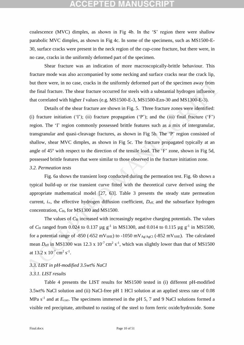
The steels tested in air, and immersed in the pH 5, 7 and 9 3.5wt% NaCl solutions
underwent ductile, cup-cone fracture accompanied by considerable necking. Typical SEM
images of these fractures are presented in Fig. 7.
The steels immersed in both pH 1 solutions (i.e. acidified 3.5wt% NaCl pH 1 and the
NaCl-free HCl solution) exhibited shear fracture. Fig. 8 presents a comparison of these
fractures viewed from the transverse side. In the pH 1 3.5wt% NaCl, the shear fracture in
MS1500-S-pH1 was quite sharp, and without visible necking. In the NaCl-free pH 1 HCl, the
shear fracture in MS1500-pH1 occurred with some plastic deformation (i.e. some necking).
ACCEPTED MANUSCRIP
T

Final.docx Page 12 of 51
Fig. 9a and 9b shows the details of the shear fracture for the two tests in the pH 1
solutions. The two fractures possessed typical shear fracture features as described previously:
(i) ‘I', (ii) ‘P’, and (iii) ‘F’ regions. The ‘P’ region of MS1500-S-pH1 was significantly
smoother than that of MS1500-pH1. Fig 9c and 9d present a magnified view of the P region.
MS1500-S-pH1 consisted of shallow and fine MVC shear dimples; whilst MS1500-pH1
possessed coarse MVC dimples. The MVC dimples in MS1500-S-pH1 were about 4 to 8
times smaller than MS1500-pH1.
Fig. 10 presents the fracture mode for MS1500 immersed in the pH 3 3.5wt% NaCl
solution at a stress rate of 0.080 MPa s-1; this fracture can be considered mixed cup-cone and
shear fracture. Fig. 10a presents the top view of the fracture. From this view, the fracture
propagation history and the features are characteristic of ductile, cup-cone fracture; i.e. (i) a
central, fracture nucleation region; and (ii) a shear lip region. There were signs of necking.
The size of the central region was unusually small, and the shear lip region appears blocky
and jagged. In contrast, the view from the transverse side shows: (i) a coarse, jagged fracture,
as shown in Fig. 10b; and (ii) surface cracks at 45o indicative of shear fracture, as shown in
Fig. 10c. Both of these features suggest some brittle behaviour.
3.4. Tensile tests
3.4.1. 0.1 M NaOH and 3.5wt% NaCl
Fig. 11 shows the typical stress-strain curves obtained from the tensile tests. The tensile tests
in solution were carried out after 24 h hydrogen pre-charging and had simultaneous hydrogen
charging during the tensile tests. Table 5 presents the values y, F, RA, and I of the four MS-
AHSS charged at (i) different potentials in 0.1 M NaOH and at (ii) EZn in 3.5wt% NaCl. In a
majority of the tests in 0.1 M NaOH, the y and F of the MS-AHSS were similar to their
corresponding tensile values in air. Only MS1500 charged at -1700 mVHg/HgO (-1602 mVSHE)
had some reduction of about 100 MPa in both y and F. The values of the elastic modulus,
evaluated from the slope of the stress-strain curve for MS1500 in air, and at -1100 mVHg/HgO,
and -1400 mVHg/HgO were quite similar; the average was about 213 GPa, close to the expected
value. In contrast, the elastic modulus for MS1500 at -1700 mVHg/HgO was about 185 GPa,
about a 10% decrease.
As the charging potential became increasingly negative, the ductility decreased and
the I values consequently increased. In the 0.1 M NaOH at -1100 mVHg/HgO, (-1002 mVSHE),
all the MS-AHSS showed no significant reduction in ductility, as reflected by the low I
ACCEPTED MANUSCRIP
T

Final.docx Page 13 of 51
values. At the higher charging potentials of -1400 and -1700 mVHg/HgO (-1302 and -1602
mVSHE), the four MS-AHSS exhibited significant decreased ductility and increased I values.
From I of less than 10 at -1100 mVHg/HgO (-1002 mVSHE), the I increased by more than 6
times at -1400 mVHg/HgO (-1302 mVSHE). Except for MS1180, there were only marginal
differences between the I values of the MS-AHSS at -1400 mVHg/HgO (-1302 mVSHE) and at -
1700 mVHg/HgO (-1602 mVSHE). For instance, MS1500 charged at -1400 mVHg/HgO (-1302
mVSHE) had an I of 51; whilst at -1700 mVHg/HgO (-1602 mVSHE), I was 52. Similarly at -
1400 mVHg/HgO (-1302 mVSHE), I for MS1180, MS1300 and MS1500 at -1700 mVHg/HgO (-
1602 mVSHE) were 49, 50 and 52, respectively. In fact, all the four steels had similar I values
at each charging potential.
In the 3.5wt% NaCl at EZn, the TH, F and RA of the four MS-AHSS were similar to
their values in air, and consequently all the I values were equal to zero.
3.4.2. Fracture characteristics in tensile tests
Similar to previous observations, the ductile and brittle behaviour of the MS-AHSS
subjected to the tensile test were characterized by cup-cone and shear fracture, respectively.
Table 5 indicates that a majority of the steels showed ductile cup-cone fracture, such as the
steels tested in (i) air; (ii) -1100 mVHg/HgO (-1002 mVSHE) and -1400 mVHg/HgO (-1302 mVSHE)
in 0.1 M NaOH; and (iii) EZn in 3.5wt% NaCl. Fig. 12 presents representative images of these
cup-cone fractures viewed from the transverse side. Except in the three steels charged at -
1400 mVHg/HgO (-1302 mVSHE), the cup-cone fractures possessed the usual characteristic
morphologies. Also, all the steels charged at -1100 mVHg/HgO (-1002 mVSHE) had surface
cracks in the neck region. The population of these cracks increased with the strength of the
steel.
All the steels charged at -1700 mVHg/HgO (-1602 mVSHE) and the MS1500 charged at -
1400 mVHg/HgO (-1302 mVSHE) in 0.1 M NaOH exhibited shear fractures. Fig. 13 presents
typical examples of these shear fractures from the transverse side. All the shear fractures
were typical, similar in features to what was previously described in 3.1.2. Also, the shear
fractures were accompanied by different amounts of necking depending on the strength of the
MS-AHSS. The amount of necking decreased as the strength of the steel increased.
The fracture features for MS980, MS1180 and MS1300 charged at -1400 mVHg/HgO (-
1302 mVSHE) had a slightly different morphology than the typical cup-cone morphology. Fig.
14 shows the fractures for MS1180 and MS1300 viewed from the transverse side. While the
typical cup-cone bears a flat profile when viewed from the transverse side, these steels had an
ACCEPTED MANUSCRIP
T

Final.docx Page 14 of 51
angled fracture profile, indicative of shear fracture. Fig. 15a shows the fracture in the
hydrogen charged MS1180 viewed normal to the fracture surface, whilst Fig. 15b shows
details of the fracture of MS1180 tested in air.
When viewed normal to the fracture surface, the features were typical of cup-cone
fracture; i.e. (i) middle section consisting of microvoid coalescence (MVC) dimples and (ii)
shear lip region containing elliptical MVC dimples. Closer inspection at higher magnification
indicated that the middle section of the fractured steels was different from the typical cup-
cone fracture. Fig. 15c-d shows details of the central region in the hydrogen-charged MS1180
and Fig. 15e shows the same details for the MS1180 tested in air. Comparing these images,
the MVC dimples in the hydrogen-charged MS1180 were (i) slightly smaller and shallower
and were (ii) interspersed with regions of brittle features similar to fisheyes.
4. Discussion
4.1. Cathodic charging in 3.5wt% NaCl
The values of TH and F for the four MS-AHSS measured using LISTs in air were in
good agreement with the corresponding values measured using conventional tensile tests by
the steel supplier. The marginal differences between the results are attributed to inter-
specimen variability. This indicates that the LIST apparatus is calibrated to give accurate
measurement of the yield and ultimate tensile strength.
Except for MS1500, the MS-AHSS showed minimal HE susceptibility after LIST at
EZn in 3.5wt% NaCl at the lowest stress rate (~3 rph motor). MS1500 had an I of 41, while
the I of the other steels ranged from 7 to 12. These results are attributed to the low hydrogen
concentration in the steels for this charging condition, as indicated by the permeation test
results in Table 3. The results for MS1500 were surprising given the relatively low hydrogen
concentration in the MS1500 after charging at EZn. Our previous study showed no to little HE
susceptibility in the four MS-AHSS at similar test conditions, with I values ranging from 0 to
10 [27]. These tests were done using a platinum electrode. In the previous study, we also did
a LIST on MS1500 charged at EZn at the lowest stress rate using a graphite electrode, and
measured an I of 47. This test was repeated in the current study, and MS1500 registered a
slightly lower I of 41. Clearly, this difference in result may be attributed to the use of
platinum counter electrode in the previous test. At sufficiently high cathodic potentials, the
use of platinum counter electrode was found to reduce the hydrogen uptake of the steel
ACCEPTED MANUSCRIP
T

Final.docx Page 15 of 51
during electrochemical charging as some platinum was electroplated onto the steel surface
[27]. Graphite electrodes did not exhibit this inhibiting effect on hydrogen uptake.
Table 2 indicated that the HE susceptibility of MS1300 and MS1500 increased when
(i) charged at the more cathodic potential -1050 mVAg/AgCl (-852 mVSHE) or when (ii) tested at
the lower stress rate, consistent with previous results in 0.1M NaOH [25]. The hydrogen
fugacity, and the subsequent hydrogen uptake of the steel, is expected to increase with
increasingly negative charging potentials. Consequently, the hydrogen sensitivity of the steel
increased [51]. Low applied stress rates favour HE since hydrogen is given ample time to
diffuse to critical sites (e.g. defects) and induce embrittlement [71], although it is emphasised
that the hydrogen concentration was uniform throughout the specimen volume as shown by
our previous modelling of the hydrogen distribution in these steels [27]. However, even
though, the hydrogen global concentration was uniform, the deformation creates micro
regions (i.e. crack tip) where H must locally diffuse in order to sustain sub-critical crack
growth, if that is the mechanism of hydrogen embrittlement. This local diffusion process
takes time and may be favoured by low applied stress rates. The fact that the H
concentration is uniform does not mean that HE would take place at any applied stress
rate.
Past studies have reported that HE susceptibility of AHSS correlates with hydrogen
concentration, whilst hydrogen concentration correlates with strength [33]. However, the
permeation test results from the current study indicate that the hydrogen concentration,
measured by CH, did not correlate with the strength. MS1300 had a somewhat higher
hydrogen concentration than MS1500. This result is consistent with our previous work [27],
wherein MS1300 showed a higher hydrogen concentration than MS1500 during cathodic
charging in 0.1 M NaOH.
In the 3.5wt% NaCl solution, the measured Deff for MS1300 and MS1500 was 12.3 x
10-7 cm2 s-1 and 13.2 x 10⁻⁷ cm2 s-1, respectively. These values were in good agreement with
the measured Deff values in the same steels (i.e. 11.3 x 10⁻⁷ cm2 s-1 for MS1300 and 10.2 x 10-
7 cm2 s-1 for MS1500) charged in 0.1 M NaOH, as reported in our previous work [27] and are
within the known scatterband of Deff values for martensitic steels [72]; i.e 1 x 10⁻⁷ to 1 x 10⁻⁵
cm2 s-1 at room temperature.
The highest hydrogen concentrations in MS-AHSS were measured after cathodic
charging at -1050 mVAg/AgCl (-852 mVSHE) in 3.5wt% NaCl; i.e. 0.137 µg g-1 in MS1300 and
0.115 µg g-1 in MS1500. Conder et al. [73] tested hydrogen concentrations in low carbon
ACCEPTED MANUSCRIP
T

Final.docx Page 16 of 51
martensite sheets (LCMS) cathodically charged in 3.5wt% NaCl solution. LCMS are steels
similar to MS-AHSS in terms of carbon content and microstructure. They measured hydrogen
concentrations of 0.2 µg g-1 and 1.3 µg g-1 at -900 mVSCE (-654 mVSHE) and -1300 mVSCE (-
1054 mVSHE) respectively. These values are significantly higher than those in the current
study, despite being in the same cathodic charging potential range. Furthermore, Conder et al
did not observe any HE susceptibility in the LCMS (f =1400 MPa) at these charging
conditions, in contrast to the considerable HE susceptibility in MS1500 at EZn (-752 mVSHE)
and at -1050 mVAg/AgCl (-852 mVSHE). This disparity in results may be due to differences in
alloy composition or microstructure, as the MS-AHSS used in the present study contained
some ferrite.
Hydrogen had no influence on both TH and f but decreased the ductility of the MS-
AHSS after charging at EZn or -1050 mVAg/AgCl (-852 mVSHE) in 3.5wt% NaCl. There were
similar observations in MS-AHSS after LIST in 0.1 M NaOH at different cathodic potentials
in our prior study [25].
The occurrence of cup-cone and shear fracture in hydrogen-influenced MS-AHSS has
been previously observed [25, 27] and the fracture mechanism of MS-AHSS in both modes
has been discussed [25]. Nevertheless, it is worthwhile to summarize these mechanisms here.
In the cup-cone fracture, the central region is the fracture nucleation region. Fracture
nucleation occurs by the formation and coalescence of micro-voids. As the fracture
propagates, the load-bearing area decreases. As the growing fracture approaches the surface,
shear stresses cause the final fracture and the shear lip region is formed. All these fracture
events occur in the necked region, when the specimen is mechanically unstable in a stress-
controlled test, like the LIST. These fracture events occur rapidly during the final fracture of
the LIST specimen.
In contrast, in the shear fracture, fracture nucleation starts at the specimen surface,
usually at a corner. The fracture extends diagonally at an angle of 45o with respect to the
direction of the tensile load, creating the characteristic angled fracture profile. As the fracture
nears the other side of the specimen, the stress is amplified in the remaining load-bearing area
and exceeds the fracture strength. Consequently, final fracture occurs. Again, the existence of
necking indicates that these fracture events all occur during final specimen fracture, and
occur quickly.
In some of the hydrogen-charged specimens, surface cracks were present in the neck
region, but there were never any cracks in the uniformly deforming part of the specimen. This
ACCEPTED MANUSCRIP
T

Final.docx Page 17 of 51
indicates that hydrogen influence only manifested during the final stage of fracture when the
neck was formed, and the specimen was mechanically unstable and undergoing final fracture.
This observation may also suggest that stress alone may not be sufficient but that dynamic
strain (deformation) is a more important (and even necessary) factor for the hydrogen
embrittlement.
4.2 Influence of pH
Table 4 indicates that, as the pH of the 3.5wt% NaCl solution decreased, the HE
susceptibility of MS1500 increased, as indicated by the corresponding increase in I values.
The steel immersed in the pH 1 NaCl solution experienced the highest degree of
embrittlement with I of 84.
The results of the test in acidified 3.5wt% NaCl gave two conclusions. Firstly, an acidic
environment enhances the HE susceptibility of MS1500 in a NaCl solution. This correlates
well with the predicted reduction of the hydrogen potential as pH decreases [64], and is
consistent with the observation that copious amounts of hydrogen bubbles were immediately
formed on the specimen upon immersion. On the other hand, the alkaline NaCl solution was
actually benign to the steel. In fact, it is known that beyond pH 10, carbon steels form a
passive layer than protects the steel from general corrosion [53]. Secondly, the presence of
NaCl in acidic solutions significantly enhances the HE susceptibility of MS1500, as indicated
by (i) the high I, (ii) the sharp shear fracture, and the (iii) fine and shallow MVC shear
dimples in MS1500-S-pH1.
These results indicate that the combination of NaCl and low pH (i.e. < pH 3) leads to
embrittlement of MS1500, and needs to be avoided in service. Pit and crevice corrosion,
especially those in marine environment, could be a concern for the steel.
The MS1500 immersed in the pH 1 HCl solutions exhibited significant reduction in
both TH and f. The hydrogen-induced solid solution softening has been explained as due to
the interaction of hydrogen with lattice dislocations [74, 75].
The hydrogen influence on the fracture characteristic of MS1500 in the acidified
3.5wt% NaCl was manifest in the transition from cup-cone to shear fracture. Except for
MS1500-S-pH3, the cup-cone and shear fractures in the steels were typical and followed the
same mechanisms as described in section 3.1.2.
The fracture feature for MS1500-S-pH3 possessed a combination of cup-cone and
shear fracture. The cup-cone mode dominated this fracture, as confirmed by the high RA and
ACCEPTED MANUSCRIP
T

Final.docx Page 18 of 51
low I. Fracture nucleated at the centre via void coalescence that was typical of cup-cone
fracture. However, the area of the central region was smaller than the typical area for steels
not influenced by hydrogen. Most of the influence of hydrogen was manifest in the shear lip
region. The shear lip area was blocky and coarse, which contrasted with the smooth areas for
typical cup-cone failures. There were also surface shear cracks. This was the first time that
such morphologies occurred in a ductile cup-cone fracture of MS1500. The most common
manifestation of hydrogen influence on ductile fracture was the occurrence of surface cracks
in the neck region.
The influence of hydrogen on fracture may occur preferentially near the surface,
because surface cracks are twice as effective as internal cracks at causing fracture because the
stress intensity factor for a surface crack is twice that of an internal crack of the same
geometry [76]. Consequently, most of the brittle shear fractures in MS-AHSS were initiated
at the surface. The fracture in MS1500-S-pH3 revealed a case where the hydrogen influence
was not sufficient to initiate fracture nucleation at the surface. This could have occurred
either due to (i) inadequate hydrogen concentration or (ii) insufficient stress. After fracture
initiation and growth had occurred in the central region, some conditions appeared that
favoured HE. The stress in the remaining load-bearing area increased significantly. Hydrogen
is also known to be released during plastic deformation and fracture [77]. It is thus possible
that some of the hydrogen in the fractured central region was released in the adjacent areas,
thereby increasing the hydrogen concentration in these regions. These conditions may have
collectively contributed to the embrittlement that occurred in the shear lip region.
4.3 EHE of MS1500
HE of steels is known to be favoured at low applied stress or strain rates, and even
static stress conditions [54]. It is therefore expected that lower HE susceptibilities are
measured in the conventional tensile test compared to other mechanical tests with slower
strain or stress rates such as the SSRT or the LIST. This would explain some of the results
obtained in the tensile test. For example, the MS-AHSS charged at EZn in 3.5wt% NaCl
showed some HE susceptibility in the LIST; but showed no hydrogen influence, as indicated
by zero I values, in the tensile test.
Table 5 indicated that HE susceptibility of MS-AHSS, at substantial stress rates with
simultaneous hydrogen charging in 0.1 NaOH, (i) increased with increasingly negative
charging potentials and (ii) and increased somewhat with increasing strength. This is
consistent with our previous tests on the four MS-AHSS using the LIST with similar charging
ACCEPTED MANUSCRIP
T

Final.docx Page 19 of 51
conditions [25]. However, the measured HE susceptibilities of the steels in the previous LIST
study, particularly for MS1180, MS1300 and MS1500 at the lowest stress rate in LISTs, were
somewhat higher than those measured in the current work. This difference in results of the
two tests could be attributed to the influence of stress rate on HE susceptibility. As earlier
mentioned, substantial stress rates can produce lower sensitivity to hydrogen, as hydrogen
does not have time to diffuse and accumulate to the necessary levels to cause embrittlement
[71].
Table 5 shows that, in the current study, all four steel showed significant HE
susceptibility at substantial stress rates with simultaneous hydrogen charging in 0.1 NaOH
when charged at -1400 mVHg/HgO (-1302 mVSHE) and at -1700 mVHg/HgO (-1602 mVSHE), and
there was marginal difference in the HE susceptibility of these four steels under these
hydrogen charging conditions. Furthermore, there were minimal differences in the HE
susceptibility of MS980, MS1300 and MS1500. These results suggest that HE susceptibility
at substantial stress rates reaches a maximum or a plateau beyond a (i) critical strength and
(ii) critical hydrogen concentration.
Our previous study found no HE susceptibility in the MS-AHSS tested under IHE
conditions [27] at the substantial stressing rates as used in this present study. Our previous
study used the same hydrogen charging as used in the current study (i.e. hydrogen charging at
-1100, -1400, and -1700 mVHg/HgO in 0.1 M NaOH), but hydrogen charging was conducted
separately in the LIST apparatus, and then the specimen was transferred to the UTM for the
subsequent mechanical testing. Our modelling of hydrogen egress indicated that 90% of the
hydrogen remained in the specimen. Nevertheless, as the hydrogen charging was the only
difference between the previous tests and the current tests, the lack of HE susceptibility in the
previous tests is attributed in part to the small amount of egress of diffusible hydrogen from
the hydrogen-charged steel during the transfer from LIST to UTM in the previous tests. It is
also possible that the rate of release of hydrogen increased during the mechanical testing [77],
which further reduced the hydrogen concentration in the prior tests.
In the current work, hydrogen charging was done in-situ, and the hydrogen charging
was maintained even during mechanical testing. This kind of test evaluates EHE. Thus, the
observed HE susceptibility in MS-AHSS in the current study was likely due to the presence
of considerable hydrogen fugacity during the mechanical tests. In addition, in-situ charging is
expected to maintain a constant hydrogen concentration throughout the specimen, whereas
the hydrogen concentration in the pre-charged specimens was expected to be zero at the
specimen surface, to increase rapidly in a diffusion profile towards the specimen centre, and
ACCEPTED MANUSCRIP
T

Final.docx Page 20 of 51
be essentially unchanged in the specimen centre, the same as during the hydrogen pre-
charging. The higher hydrogen susceptibility under in-situ charging conditions can therefore
be attributed to the low hydrogen concentrations at the surface for pre-charged specimens. In
contrast, for in-situ hydrogen charging, the substantial hydrogen concentrations at the surface
enabled hydrogen fracture events to be initiated at the specimen surface. These results leads
to the conclusion that the EHE of MS-AHSS can occur more easily and at a lower equivalent
fugacity than IHE, consistent with previous studies on conventional steels [68]. For IHE to
occur, the existing hydrogen concentration should be high enough to accommodate for
hydrogen loss during the mechanical test, particularly at the specimen surface.
It is also worth stressing that these results indicate that the HE susceptibility of a
hydrogen charged specimen is lost quickly under IHE conditions, within 10 min, due to the
lowering of the hydrogen concentration in the surface. The hydrogen embrittlement
susceptibility can be lost without the requirement for a low hydrogen concentration
throughout the specimen; it is only necessary for there to be a low surface hydrogen
concentration.
Only MS1500 tested at -1700 mVHg/HgO (-1602 mVSHE) in 0.1 M NaOH exhibited a
reduction in TH and f, in the present tests under EHE conditions The stress-strain curve
presented in Fig. 11 indicated a decrease in the elastic modulus, E, of the steel; indicated by
the reduction in the slope of the elastic region. The values of the elastic modulus, evaluated
from the slope of the stress-strain curve for MS1500 in air, and at -1100 mVHg/HgO, and -1400
mVHg/HgO were quite similar; the average was about 213 GPa, close to the expected value. In
contrast, the elastic modulus for MS1500 at -1700 mVHg/HgO was about 185 GPa, about a 10%
decrease. This observed weakening of the atomic bonds is different to the solid solution
softening of the MS-AHSS due to hydrogen [74, 75]. Solid solution softening is caused by
hydrogen lowering the repulsive force between dislocations, making dislocation slip easier
[74, 78]. In contrast, the decrease in the elastic modulus relates to the decreasing the cohesive
bond strength between atoms [79-81] so that fracture becomes easier.
4.4 Fracture mechanism at substantial stress rates
Similar to observations in the other tests, the full influence of hydrogen on MS-AHSS
subjected to substantial-applied stress rates was manifested in the occurrence of shear
fractures.
ACCEPTED MANUSCRIP
T

Final.docx Page 21 of 51
The influence of hydrogen on the ductile, cup-cone fracture is evident in Fig. 12 and
Fig. 15. Hydrogen induced the formation of surface cracks in the neck region of the steels
charged in -1100 mVHg/HgO (-1002 mVSHE) in 0.1 M NaOH. The increase in the number of
these cracks with increasing strength is consistent with increasing strength correlating with
increased hydrogen sensitivity. Hydrogen also induced the formation of brittle fracture events
that were manifest as fisheyes interspersed with the MVC dimples present in the central
fracture initiation region.
This was our first case where hydrogen had clearly influenced the central crack
initiation region in a cup-cone fracture. In our past work, fisheyes were present in the shear
fracture of the two strongest MS-AHSS; namely MS1300 and MS1500, for LIST at the
highest hydrogen fugacity and at the slowest stress rate [25]. These fisheyes were mostly
found in the fracture propagation region, also interspersed with MVC shear dimples and
surrounded by MVC dimples. One conclusion derived from those observations was that
fisheye formation was favoured at slow stress rates, as slow rates allow hydrogen to diffuse
into critical parts and cause embrittlement. Alternatively, fisheyes may be associated with a
process similar to solid solution softening by hydrogen, which must be associated with the
rearrangement of major dislocation arrangements by hydrogen to cause increased plasticity
and to decrease the yield stress, which were experimentally observed to be slow processes.
Similarly, fisheyes may be associated with such hydrogen caused dislocation rearrangement,
although it is stressed that the actual fisheye formation was an extremely fast process that
competed with the final ductile fracture process when the specimen was mechanically
unstable and was actively undergoing final fracture.
In contrast, in the current study, the fisheyes were (i) also found in the softer steels
(MS980, MS1180 and MS1300) and (ii) occurred at much higher stress rates. In light of these
new observations, a review is needed of the mechanism of (i) hydrogen-influenced cup-cone
fracture of MS-AHSS and (ii) fisheye formation at substantial stress rates. In our prior study
where there were fisheyes under testing conditions of low applied stress rates, the fisheyes
occurred during the fracture propagation stage of the shear fracture. These fisheye fracture
events occurred in competition with the overall ductile micro-void coalescence processes. It
is expected that there was a similar situation in the present study where the brittle fisheye
fracture processes were occurring simultaneously with the ductile micro-void processes.
At this point, we propose a mechanism for fisheye formation during the fracture
initiation stage. At the point of maximum load, since no fracture nucleation occurred at the
surface due to lack of hydrogen influence, then microvoid nucleation and coalescence
ACCEPTED MANUSCRIP
T

Final.docx Page 22 of 51
initiated in the centre of the specimen. Hydrogen is also known to enhance dimple formation
since it can induce localized plasticity [82]. As MVC dimples coalesce, the hydrogen released
by the dimples accumulates locally and reaches a critical concentration. Consequently, brittle
fracture occurs in these hydrogen-enriched zones and creating the ‘fisheye’ structure that was
interspersed with the MVC dimples, and surrounded by MVC dimples.
It is clear that when the hydrogen concentration exceeds the critical amount in MS-
AHSS, hydrogen embrittlement occurred as manifested by the typical shear fracture. In this
case, the fracture often started at the surface (assumed at a stress concentrator), then
propagated across the specimen to cause specimen rupture. This occurred for MS1500
charged at -1400 mVHg/HgO (-1302 mVSHE). However, for the same charging condition,
MS980, MS1180 and MS1300 did not exhibit shear fracture, but instead, these three steels
exhibited the hydrogen influenced cup-cone fracture presented in Fig 15, despite having I
values almost the same as those of MS1500. This behaviour could be due to the difference in
hydrogen sensitivity of the steels. It is known that as steels become stronger, the critical
hydrogen concentration to cause HE decreases [54]. It may also be argued that the difference
could be due to a difference in the hydrogen concentration of the steels. However, our past
work has already proven that (i) there was no significant difference in the hydrogen
concentration of the four MS-AHSS, and (ii) there was no correlation between the hydrogen
concentration and the mechanical strength of the steels [27]. It could also be related to the
ease with which hydrogen can initiate cracks at the ultimate tensile strength of the steel.
It needs to be considered that in our previous LIST test of MS1300 at -1400 mVHg/HgO
(-1302 mVSHE) and at 30 rph [25], the steel exhibited almost similar HE susceptibility (I =
53) but with shear fracture. This was in contrast to the cup-cone fracture in the current study,
and implies that the occurrence of shear fracture was also influenced by the stress rate.
5. Conclusions
1. There was minimal influence of hydrogen for MS980, MS1180 and MS1300 in the LIST
in 3.5 wt% NaCl at EZn, (-950 mVAg/AgCl (-752 mVSHE)), whereas MS1500 showed some
HE susceptibility for this test condition.
2. The HE susceptibility of MS1300 and MS1500 was increased at the more negative
potential of -1050 mVAg/AgCl (-852 mVSHE) in 3.5 wt% NaCl, and was increased at the
lower applied stress rate.
ACCEPTED MANUSCRIP
T

Final.docx Page 23 of 51
3. The hydrogen concentration of MS1300 and MS1500 increased with increasingly
negative applied potential in 3.5 wt% NaCl. However, there was no clear correlation
between hydrogen concentration with the mechanical strength of the two steels.
4. The influence of hydrogen on MS1500 increased with decreasing pH in 3.5 wt% NaCl.
At the same pH, the presence of NaCl increased HE susceptibility. The combination of
NaCl and a critically low pH could cause HE in MS-AHSS.
5. At substantial stress rates and high hydrogen fugacity, considerable HE susceptibility
occurred in the four MS-AHSS. MS1500 with in-situ hydrogen charging at -1700
mVHg/HgO (-1602 mVSHE) in 0.1 M NaOH showed significant solid solution softening by
hydrogen (lowering of yield strength by 100 MPa) and a decrease of elastic modulus by
10%.
6. There was some degradation of mechanical strength (i.e. TH and f) of MS-AHSS (i) in
the pH 1 solutions, and (ii) at substantial stress rates at the most negative charging
potential in 0.1 M NaOH. This is attributed to solid solution softening by hydrogen.
7. Hydrogen influenced (i) the fracture initiation in the cup-cone fracture in MS1500
immersed in pH 3 3.5 wt% NaCl, and (ii) and the final fracture in the cup-cone fracture
in M980, MS1180 and MS1300 charged at -1400 mVHg/HgO (-1302 mVSHE) at substantial
stress rates. This manifested as fisheyes present in the central fracture initiation region,
and the formation of coarse and jagged fractures in the shear lip region.
Acknowledgments
This research is supported by the Baosteel-Australia Joint Research & Development Centre
(BAJC) Grant BA13037, with linkage to Baoshan Iron & Steel Co., Ltd. (Shanghai, China).
The authors also acknowledge the facilities, and the scientific and technical assistance, of the
Australian Microscopy & Microanalysis Research Facility at the Centre for Microscopy and
Microanalysis, The University of Queensland.
ACCEPTED MANUSCRIP
T

Final.docx Page 24 of 51
References
[1] WorldAutoSteel. Advanced High-Strength Steels Application Guidelines V5.0. Published
May 5, 2014. . Available from http://www.worldautosteel.org. Accessed on July 7, 2014.
[2] Automotive Applications Council. AHSS 101-The Evolving Use of Advanced High-
Strength Steels for Automotive Application. 2011. Available from http://www.autosteel.org.
Accessed on April 20, 2014.
[3] X. Zhu, Z. Ma, L. Wang. Current Status of Advanced High Strength Steel for Auto-
making and its Development in Baosteel. Available from http://www.baosteel.com. Accessed
on May 21. 2014.
[4] ULSAB-AVC Consortium. ULSAB-AVC (Advanced Vehicle Concepts) Overview
Report. Available from http://www.autosteel.org. Accessed on April 12, 2014.
[5] O. Bouaziz, H. Zurob, M. Huang, Driving Force and Logic of Development of Advanced
High Strength Steels for Automotive Applications, Steel Research Int., 84 (2013) 937-947.
[6] ArcellorMittal. Usibor: Steels for Hot Stamping. Available from
http://fce.arcelormittal.com. Accessed on April 12, 2014.
[7] R.Z. Mallen, S. Tarr, J. Dykeman. Recent Applications of High Strength Steels in North
American Honda Production, Great Designs in Steel Seminar. Michigan, USA. Apr, 2008.
Available from http://www.autosteel.org. Accessed on July 22, 2014.
[8] I. Han. Advanced High-Strength Steel Technologies in the 2014 Chevy Spark, General
Motors, Great Designs in Steel 2014. Michigan, USA. May 2014. Available from
http://www.autosteel.org. Accessed on July 24, 2017.
[9] E. Villalba, A. Atrens, Metallurgical aspects of rock bolt stress corrosion cracking, Mater.
Sci. Eng. A, 491 (2008) 8-18.
[10] E. Villalba, A. Atrens, Hydrogen Embrittlement and Rock Bolt Stress Corrosion
Cracking, Eng. Fail. Anal., 16 (2009) 164-175.
[11] E. Villalba, A. Atrens, SCC of commercial steels exposed to high hydrogen fugacity,
Eng. Fail. Anal., 15 (2008) 617-641.
[12] E. Villalba, A. Atrens, An evaluation of steels subjected to rock bolt SCC conditions,
Eng. Fail. Anal., 14 (2007) 1351-1393.
[13] E. Gamboa, A. Atrens, Material influence on the stress corrosion cracking of rock bolts,
Eng. Fail. Anal, 12 (2005) 201-235.
[14] E. Gamboa, A. Atrens, Stress corrosion cracking fracture mechanisms in rock bolts, J
Mater. Sci. , 38 (2003) 3813-3829.
[15] E. Gamboa, A. Atrens, Environmental influence on the stress corrosion cracking of rock
bolts, Eng. Fail. Anal, 10 (2003) 521-558.
[16] S. Ramamurthy, A. Atrens, Stress corrosion cracking of high-strength steels, Corros.
Rev., 31 (2013) 1-31.
[17] A. Oehlert, A. Atrens, SCC Propagation in Aermet 100, J. Mater. Sci. , 33 (1998) 775-
781.
[18] A. Atrens, Z.F. Wang, ESEM observations of SCC initiation for 4340 high strength steel
in distilled water, J Mater. Sci., 33 (1998) 405-415.
[19] A. Atrens, A. Oehlert, Linearly-increasing-stress testing of carbon steel in 4 N NaNO3
and on Bayer liquor, J Mater. Sci., 33 (1998) 783-788.
[20] R.M. Rieck, A. Atrens, I.O. Smith, The Role of Crack Tip Strain Rate in the Stress
Corrosion Cracking of High Strength Steels in Water, Met. Trans, 20A (1989) 889-895.
[21] L. Duprez, K. Verbeken, M. Verhaege, Effect of hydrogen on the mechanical properties
of multiphase high strength steels, in: Effects of hydrogen on materials: Proceedings of the
2008 International Hydrogen Conference, Grand Teton National Park, WY, USA, 2009, pp.
62-69.
ACCEPTED MANUSCRIP
T

Final.docx Page 25 of 51
[22] T. Depover, O. Monbaliu, E. Wallaert, K. Verbeken, Effect of Ti, Mo and Cr based
precipitates on the hydrogen trapping and embrittlement of Fe-C-X Q&T alloys, Int. J.
Hydrogen Energ., 40 (2015) 16977-16984.
[23] D. Pérez Escobar, C. Miñambres, L. Duprez, K. Verbeken, M. Verhaege, Internal and
surface damage of multiphase steels and pure iron after electrochemical hydrogen charging,
Corros. Sci., 53 (2011) 3166-3176.
[24] Q. Liu, A. Atrens, The influence of hydrogen on the low cycle fatigue behavior of
medium strength 3.5NiCrMoV steel studied using notched specimens, Adv.Eng. Mater., DOI:
10.1002/adem.201700680 (2017).
[25] J. Venezuela, Q. Liu, M. Zhang, Q. Zhou, A. Atrens, The influence of hydrogen on the
mechanical and fracture properties of some martensitic advanced high strength steels studied
using the linearly increasing stress test, Corros. Sci., 99 (2015) 98-117.
[26] J. Venezuela, Q. Liu, M. Zhang, Q. Zhou, A. Atrens, A review of hydrogen
embrittlement of martensitic advanced high-strength steels, Corros. Rev., 34 (2016) 153-186.
[27] J. Venezuela, Q. Zhou, Q. Liu, M. Zhang, A. Atrens, Influence of hydrogen on the
mechanical and fracture properties of some martensitic advanced high strength steels in
simulated service conditions, Corros. Sci., 111 (2016) 602-624.
[28] Q. Liu, Q. Zhou, J. Venezuela, M. Zhang, A. Atrens, Hydrogen Concentration in Dual‐Phase (DP) and Quenched and Partitioned (Q&P) Advanced High‐Strength Steels (AHSS)
under Simulated Service Conditions Compared with Cathodic Charging Conditions, Adv.
Engg. Mater., 18 (2016) 1588-1599.
[29] Q. Liu, J. Venezuela, M. Zhang, Q. Zhou, A. Atrens, Hydrogen trapping in some
advanced high strength steels, Corros. Sci., 111 (2016) 770-785.
[30] Q. Liu, Q. Zhou, J. Venezuela, M. Zhang, J.Wang, A. Atrens, A review of the influence
of hydrogen on the mechanical properties of DP, TRIP, and TWIP advanced high-strength
steels for auto construction, Corros. Rev., 34 (2016) 127-152.
[31] T. Depover, L. Duprez, K. Verbeken, E. Wallaert, M. Verhaege, In-situ mechanical
evaluation of hydrogen embrittlement for TRIP, FB, DP and HSLA steels, in: Steely
Hydrogen Conference, Ghent Belgium, 2011, pp. 31-42.
[32] T. Depover, D. Escobar, E. Wallaert, Z. Zermout, K. Verbeken, Effect of hydrogen
charging on the mechanical properties of advanced high strength steels, Int. J. Hydrogen
Energ., 39 (2014) 4647-4656.
[33] M. Loidl, O. Kolk, S. Veith, T. Gobel, Characterization of hydrogen embrittlement in
automotive advanced high strength steels, Mat.-wiss. u.Werkstofftech, 42 (2011).
[34] G. Lovicu, M. Bottazzi, F. D’Aiuto, M. De Sanctis, A. Dimatteo, C. Santus, R.
Valentini, Hydrogen embrittlement of automotive advanced high-strength steels, Metall.
Mater. Trans. A., 43 (2012) 4075-4087.
[35] J.A. Ronevich, J.G. Speer, D.K. Matlock, Hydrogen embrittlement of commercially
produced advanced high strength steels, SAE Int. J. Mater. Manuf., 3 (2010) 255-267.
[36] J. Venezuela, Q. Zhou, Q. Liu, M. Zhang, A. Atrens, Hydrogen trapping in some
automotive martensitic advanced high-strength steels, Adv. Eng. Mater., 1700468.
doi:10.1002/adem.201700468 (2017).
[37] J. Venezuela, E. Gray, C.V. Tapia-Bastidas, Q. Liu, Q. Zhou, M. Zhang, A. Atrens,
Equivalent hydrogen fugacity during electrochemical charging of some martensitic advanced
high-strength steels, Corros Sci, 127 (2017) 45-58.
[38] Q. Liu, E. Gray, J. Venezuela, Q. Zhou, C. Tapia-Bastidas, M. Zhang, A. Atrens,
Equivalent Hydrogen Fugacity during Electrochemical Charging of 980DP Steel Determined
by Thermal Desorption Spectroscopy, Advanced Engineering Materials, DOI:
10.1002/adem.201700469 (2018) (2017).
ACCEPTED MANUSCRIP
T

Final.docx Page 26 of 51
[39] Q. Liu, Q. Zhou, J. Venezuela, M. Zhang, A. Atrens, Hydrogen influence on some
advanced high-strength steels, Corrosion Science, 125 (2017) 114-138.
[40] Q. Liu, A. Atrens, A critical review of the influence of hydrogen on the mechanical
properties of medium strength steels, Corros. Rev., 31 (2013) 85-104.
[41] S. Ramamurthy, W.M.L. Lau, A. Atrens, Influence of the applied stress rate on the stress
corrosion cracking of 4340 and 3.5NiCrMoV steels under conditions of cathodic hydrogen
charging. , Corros. Sci., 53 (2011) 2419-2429.
[42] S. Ramamurthy, A. Atrens, The influence of applied stress rate on the stress corrosion
cracking of 4340 and 3.5NiCrMoV steels in distilled water at 30 °C, Corros. Sci., 52 (2010)
1042-1051.
[43] J.Q. Wang, A. Atrens, D.R. Cousens, P.M. Kelly, C. Nockolds, S. Bulcock,
Measurement of grain boundary composition for X52 pipeline steel, Acta Mater., 46 (1998).
[44] H. Lukito, Z. Szklarska-Smialowska, Susceptibility of medium-strength steels to
hydrogen-induced cracking, Corros. Sci., 39 (1997) 2151-2169.
[45] A. Oehlert, A. Atrens, Environmental Assisted Fracture For 4340 Steel in Water and Air
of Various Humidities, J Mater. Sci., 32 (1997) 6519-6523.
[46] A. Oehlert, A. Atrens, Initiation and Propagation of Stress Corrosion Cracking in AISI
4340 and 3.5NiCrMoV Rotor Steel in Constant Load Tests, Corros. Sci., 38 (1996) 1159-
1170.
[47] S. Ramamurthy, A. Atrens, The Stress Corrosion Cracking of As-Quenched 4340 and
3.5NiCrMoV Steels Under Stress Rate Control in Distilled Water at 90C Corros. Sci., 34
(1993) 1385-1402.
[48] N.N. Kinaev, D.R. Cousens, A. Atrens, The Crack Tip Strain Field of AISI 4340 Part III
Hydrogen Influence, J Mater. Sci. , 34 (1999) 4931-4936.
[49] M.C. Zhao, M. Liu, A. Atrens, Y.Y. Shan, K. Yang, Effect of applied stress and
microstructure on sulfide stress cracking resistance of pipeline steels subject to hydrogen
sulfide, Mater. Sci. Eng. A, (2008) 43-47.
[50] R.P. Gangloff, Hydrogen assisted cracking of high strength alloys, in: I. Milne, R.O.
Ritchie, B. Karihaloo (Eds.) Comprehensive structural integrity Vol. 6, Environmentally
Assisted Fracture, Elsevier, 2003, pp. 31 - 101.
[51] S. Lynch, Hydrogen embrittlement phenomena and mechanisms, Corros. Rev., 30
(2012) 105-123.
[52] C. Willan. Hydrogen Embrittlement A Historical Overview. Available from
www.omegaresearchinc.com/. Accessed on July 25, 2017.
[53] D.A. Jones, Principles and prevention of corrosion, 2nd Ed., Prentice Hall, NJ, 1996.
[54] M. R. Louthan Jr, Hydrogen Embrittlement of Metals: A Primer for the Failure Analyst,
J Fail. Anal. and Preven., 8 (2008) 289-307.
[55] A. Atrens, C.C. Brosnan, S. Ramamurthy, A. Oehlert, I.O. Smith, Linearly increasing
stress test (LIST) for SCC research, Meas. Sci. Technol., 4 (1993) 1281-1292.
[56] J. Salmond, A. Atrens, SCC of copper using the linearly increasing stress test, Scripta
Met. Mater., 26 (1992) 1447-1450.
[57] A. Atrens, J.Q. Wang, K. Stiller, H.O. Andren, Atom probe field ion microscope
measurements of carbon segregation at an alpha:alpha grain boundary and service failures by
intergranular stress corrosion cracking, Corros. Sci., 48 (2006) 79-92.
[58] N. Winzer, A. Atrens, W. Dietzel, G. Songa, K.U. Kainer, Comparison of the linearly
increasing stress test and the constant extension rate test in the evaluation of transgranular
stress corrosion cracking of magnesium, Mater. Sci. Eng. A, 472 (2008) 97-106.
[59] S. Ramamurthy, W.M.L Lau, A. Atrens, Influence of the applied stress rate on the stress
corrosion cracking of 4340 and 3.5NiCrMoV steels under conditions of cathodic hydrogen
charging, Corrosion Science, 53 (2011) 2419-2429.
ACCEPTED MANUSCRIP
T

Final.docx Page 27 of 51
[60] Q. Liu, B. Irwanto, A. Atrens, The Influence of Hydrogen on 3.5NiCrMoV steel studied
using the linearly increasing stress test. , Corros. Sci., 67 (2013) 193-203.
[61] Q. Liu, B. Irwanto, A. Atrens, Influence of hydrogen on the mechanical properties of
some medium-strength Ni–Cr–Mo steels, Mater. Sci. Eng. A, 617 (2014) 200-210.
[62] F. Cao, Z. Shi, G. Song, M. Liu, M. Dargusch, A. Atrens, Stress corrosion cracking of
several solution heat-treated Mg–X alloys, Corros. Sci., 96 (2015) 121-132.
[63] Q. Liu, A.D. Atrens, Z. Shi, K. Verbeken, A. Atrens, Determination of the hydrogen
fugacity during electrolytic charging, Corros. Sci., 87 (2014) 239-258.
[64] M. Pourbaix, Atlas of electrochemical equilibria in aqueous solutions (English edition),
Pergamon press, Oxford, 1966.
[65] M. Nishimoto, J. Ogawa, I. Muto, Y. Sugawara, N. Hara, Simultaneous visualization of
pH and Cl− distributions inside the crevice of stainless steel, Corrosion Science, 106 (2016)
298-302.
[66] I. M. Bernstein, R. Garber, G. M. Pressouyre, Effect of Hydrogen on Behavior of
Materials, in: A.W. Thompson, I.M. Bernstein (Eds.) Effect of hydrogen on behavior of
materials, TMS-AIME, New York, 1976, pp. 37.
[67] W.W. Gerberich, T. Livne, X. Chen, Modeling Environmental Effects on Crack Growth
Processes, , TMS, Warrendale, PA, 1985.
[68] R.J. Walter, R.P. Jewett, W.T. Chandler, On the mechanism of hydrogen-environment
embrittlement of iron- and nickel-base alloys, Mater. Sci. Eng., 5 (1970) 99-110.
[69] T. Zakroczymski, Adaptation of the electrochemical permeation technique for studying
entry, transport and trapping of hydrogen in metals, Electrochim. Acta, 51 (2006) 2261-2266.
[70] Q. Liu, A. Atrens, Reversible hydrogen trapping in a 3.5NiCrMoV medium strength
steel, Corros. Sci., 96 (2015) 112-120.
[71] M. Hashimoto, R.M. Latanision, The Role of Dislocations during Transport of Hydrogen
in Hydrogen Embrittlement of Iron, Metall. Trans. A. , 19A (Nov 1988) 2799-2803.
[72] T. Bollinghaus, H. Hoffmeister, C. Middel, Scatterbands for hydrogen diffusion
coefficients in steels having ferritic or martensitic microstructures and steels having an
austenitic microstructure at room temperature, Weld World, 37 (1996) 16-23.
[73] R.J. Conder, P. Felton, R. Burke, P. Dent, Hydrogen Embrittlement Testing Of High
Strength Low Carbon Martensitic Steels, Corrosion 2015, NACE International, San Antonio,
Texas, in, 2010.
[74] C.D. Beachem, A new model for hydrogen assisted cracking (Hydrogen embrittlement),
Metall. Trans., 3 (1972) 437 – 451.
[75] M. Nagumo, Fundamentals of Hydrogen Embrittlement, Springer, Singapore, 2016.
[76] G. Dieter, Mechanical Metallurgy, 3rd Ed., McGraw-Hill, NY, USA, 1988.
[77] H. Shoda, H. Suzuki, K. Takai, Y. Hagiwara, Hydrogen Desorption Behavior of Pure
Iron and Inconel 625 during Elastic and Plastic Deformation, ISIJ Int., 50 (2010) 115-123.
[78] H.K. Birnbaum, P.Sofronis, Hydrogen-enhanced localized plasticity - a mechanism for
hydrogen-related fracture, Mater. Sci. Engg. A, 176 (1994) 191-202.
[79] A.R. Troiano, The role of hydrogen and other interstitials in the mechanical behavior of
metals, Trans. ASM, 52 (1960) 54 - 80.
[80] R.A. Oriani, A mechanistic theory of hydrogen embrittlement of steels, Ber. Bunsenges.
Phys. Chem., (1972) 848 - 857.
[81] R. A. Oriani, P. H. Josephic, Testing of the decohesion theory of hydrogen-induced
crack propagation, Scripta Metall, 6 (1972) 681-688.
[82] D.C. Ahn, P. Sofronis, R.H. Dodds, On hydrogen-induced plastic flow localization
during void growth and coalescence, Int. J. Hydrogen Energ., 32 (2007) 3734-3742.
ACCEPTED MANUSCRIP
T

Final.docx Page 28 of 51
Fig. 1. Schematic of a LIST specimen. Dimensions are in mm.
The specimen thicknesses were: (i) 1.5 mm for MS980, (ii)
1.70 mm for MS1180, (iii) 1.20 mm for MS1300, and (iv)
1.18 mm for MS1500
ACCEPTED MANUSCRIP
T

Final.docx Page 29 of 51
Fig. 2. Typical plots of potential drop versus stress obtained
from a LIST. The threshold stress, TH
, was determined as the
transition stress corresponding to the significant increase in
the slope. The two plots have been displaced vertically for
ease of viewing.
ACCEPTED MANUSCRIP
T

Final.docx Page 30 of 51
Fig. 3. (a) A typical ductile cup-cone fracture (specimen:
MS1500-A-30 tested in air) and (b) a typical shear fracture
(specimen: MS1500-E-3 tested in 3.5wt%NaCl). The arrow
shows the direction of the applied tensile load. The mean
thickness of the MS1500 specimen was 1.18 mm.
a b
ACCEPTED MANUSCRIP
T

Final.docx Page 31 of 51
Fig. 4. (a) Normal (or top) view of a typical cup-cone
fracture; the arrows show the fracture propagation directions.
High magnification images show details of (b) the central (C)
region and (c) shear lip (S) region consisting of round and
parabolic MVC dimples, respectively. (Specimen: MS1500-A-
30 tested in air).
ACCEPTED MANUSCRIP
T

Final.docx Page 32 of 51
ACCEPTED MANUSCRIP
T

Final.docx Page 33 of 51
Fig. 5. (a) Normal (or top) view of a typical shear fracture.
The arrows show the fracture propagation directions. High
magnification images show details of (b) the fracture initiation
(‘I’) region with a mixture of intergranular and quasi-cleavage
fracture features; (c) fracture propagation (‘P’) region
consisted of shallow shear MVC dimples; and (d) final
fracture (‘F’) region consisting of brittle features similar to
those in region “I”. (specimen: MS1500-E-3 tested in 3.5wt%
NaCl).
ACCEPTED MANUSCRIP
T

Final.docx Page 34 of 51
ACCEPTED MANUSCRIP
T

Final.docx Page 35 of 51
Fig. 6 (a) A typical permeation transient loop obtained from
the permeation tests using MS1500 steel. The solutions in the
entry cell and exit cell consisted of 3.5 wt% NaCl and 0.1 M
NaOH, respectively. The permeation transients were as
follows: (i) successive decay transients from -1050 to -950,
then -950 to -850 mVAg/AgCl
; and (ii) successive rise transients
from -850 to -950, then -950 to -1050 mVAg/AgCl
. The arrows
indicate the time at which the new constant potential was
applied to the hydrogen entry side of the permeation
specimen. The permeation transient measured the current
density at the exit side of the permeation specimen (which
represents the flux of hydrogen, which had permeated through
the specimen. (b) An experimental rise permeation transient (-
850 to -950 mVAg/AgCl
) fitted to the appropriate mathematical
model.
ACCEPTED MANUSCRIP
T

Final.docx Page 36 of 51
ACCEPTED MANUSCRIP
T
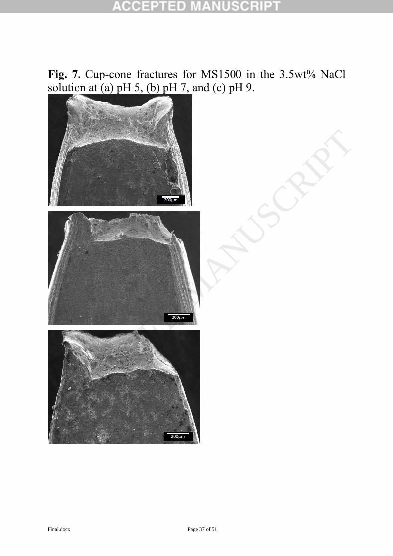
Final.docx Page 37 of 51
Fig. 7. Cup-cone fractures for MS1500 in the 3.5wt% NaCl
solution at (a) pH 5, (b) pH 7, and (c) pH 9.
ACCEPTED MANUSCRIP
T

Final.docx Page 38 of 51
Fig. 8. Comparison of the shear fractures for MS1500 in the
(a) pH 1 3.5wt% NaCl solution and in the (b) NaCl-free pH 1
HCl solution.
ACCEPTED MANUSCRIP
T

Final.docx Page 39 of 51
Fig. 9. Comparison of the shear fracture for MS1500 in (a) the
NaCl-free pH 1 HCl solution and (b) pH 1 3.5wt% NaCl
solution. Details of the ‘P’ region for (c) MS1500-pH1 and (d)
MS1500-S-pH1. Arrow shows direction of crack
propagation. .
ACCEPTED MANUSCRIP
T

Final.docx Page 40 of 51
Fig. 10. Details of the fracture surface for MS1500 after LIST
in pH 3 3.5 wt% NaCl solution at a stress rate of 0.08 MPa s-1
;
viewed (a) normal to the fracture surface, and from (b) the
wide transverse side and (c) the short transverse side. This
fracture possessed a mix of cup-cone and shear fracture
features
ACCEPTED MANUSCRIP
T

Final.docx Page 41 of 51
Fig. 11. Stress-strain curve for MS1500 in air, and with
precharging and simultaneous in-situ hydrogen charging at -
1100, -1400 and -1700 mVHg/HgO
in 0.1 M NaOH
ACCEPTED MANUSCRIP
T

Final.docx Page 42 of 51
Fig. 12. Cup-cone fractures in tensile test specimens as
viewed from the transverse side: (a) MS980 and (b) MS1500
charged at Ezn
in 3.5 wt% NaCl. (c) MS980 and (d) MS1500
charged at -1100 mVHg/HgO
in 0.1 M NaOH; all showing
surface cracks in the neck region.
ACCEPTED MANUSCRIP
T

Final.docx Page 43 of 51
Fig. 13. Fracture images of (a) MS980, (b) MS1180, (c)
MS1300 and (b) MS1500 all charged at -1700 mVHg/HgO
in 0.1
M NaOH. The view is from the transverse side. All the
fractures were shear, but accompanied by decreasing amounts
of necking with increasing strength of the MS-AHSS.
ACCEPTED MANUSCRIP
T

Final.docx Page 44 of 51
Fig. 14. Details of the fracture of (a) MS1180 and (b) MS1300
charged at -1400 mVHg/HgO
in 0.1 M NaOH viewed from the
wide transverse side. These specimens possess a shear fracture
profile but with a fracture mode that was akin to a cup-cone
fracture
ACCEPTED MANUSCRIP
T
Final.docx Page 45 of 51
Fig. 15. Details of the fracture surface of MS1180 (a) charged at -
1400 mVHg/HgO
in 0.1 M NaOH compared with the same steel tested in
(b) air. Arrows shows crack propagation directions. Magnified images
of the central region of : (c-d) hydrogen charged MS1180 consisting
of a mix of MVC dimples interspersed with circular brittle regions
similar to fisheyes, and (e) MS1180 in air consisting of typical MVC
dimples.
ACCEPTED MANUSCRIP
T

Final.docx Page 46 of 51
Table 1 Chemical composition (in wt %), microstructural composition (in %), and
mechanical properties of the MS-AHSS.
Steel
designat
ion
C Si M
n
S P Al Ti Cr %
martens
ite
%
ferrit
e
Yield
stress,
MPa
Tensile
stress,
MPa
ef,
%
MS980 0.1
2
0.
37
1.
63
<0.
01
<0.
01
0.0
3
0.0
4
0.0
2
70 30 883 1070 5
MS1180 0.1
5
0.
37
1.
64
<0.
01
<0.
01
0.0
3
0.0
3
0.0
2
84 16 1176 1355 3
MS1300 0.1
5
0.
39
1.
67
<0.
01
<0.
01
0.0
4
0.0
3
0.0
1
90 10 1108 1367 2.9
MS1500 0.1
9
0.
36
1.
51
<0.
01
<0.
01
0.0
4
0.0
3
0.0
2
92 8 1326 1512 2.4
ACCEPTED MANUSCRIP
T

Final.docx Page 47 of 51
Table 2 LIST results for different MS-AHSS in (a) air or in (b) 3.5wt% NaCl solution,
at the two charging potentials: (i) EZn = -950 mVAg/AgCl (-752 mVSHE) and (ii) -1050
mVAg/AgCl (-852 mVSHE). The applied stress rates are given and were equivalent to those
produced by the 30 (intermediate) and 3 (slow) rph motors. Unless otherwise noted in
‘Remarks’, fractures were ductile, accompanied by necking and cup-cone fracture, and
MVC dimples present on fracture surface. n/a means not applicable.
Speci
men
design
ation
E
nv
ir
on
m
en
t
Pote
ntial
,
mVA
g/AgCl
App
lied
stres
s
rate,
MPa
s-1
Thre
shold
or
yield
stres
s,
TH,
MPa
(±5)
Fract
ure
stress
,
UTS,
F,
MPa
(±2)
Redu
ction
in
area,
RA,
%
Hydro
gen
embrit
tlemen
t
index,
I
Remarks
MS980-
A-30
Ai
r
n/a 0.06
4
910 1040 73 n/a
MS118
0-A-30
Ai
r
n/a 0.05
4
1170 1342 71 n/a
MS130
0-A-30
Ai
r
n/a 0.08
0
1120 1308 65 n/a
MS150
0-A-30
Ai
r
n/a 0.08
0
1310 1518 61 n/a
MS980-
Ezn-3
N
aC
l
-950 0.00
64
900 1010 68 7 .
MS118
0-Ezn-3
N
aC
l
-950 0.00
54
1175 1310 66 7
MS130
0-Ezn-3
N
aC
l
-950 0.00
80
1180 1350 57 12
MS150
0-Ezn-3 N
a
C
l
-950 0.00
80
1320 1496 36 41 Shear fracture
accompanied by
some amount of
necking.
MS130
0-E-30
N
aC
l
-1050 0.08
0
1105 1296 58 11
MS130
0-E-3 N
a
C
l
-1050 0.00
80
1085 1298 34 48 Shear fracture
accompanied by
some amount of
necking. MS150
0-E-30
N
aC
l
-1050 0.08
0
1260 1490 53 13 Ductile;
necking and
cup-cone
fracture, but
with shallow
surface
fractures in the
neck.
ACCEPTED MANUSCRIP
T

Final.docx Page 48 of 51
MS150
0-E-3 N
a
C
l
-1050 0.00
80
1240 1526 13 79 Sharp shear
fracture without
necking. Surface
fractures found
near fracture lip.
Table 3 Deff and CH for MS1300 and MS1500 obtained from decay and rise transients in
the permeation experiments. The solutions in the entry cell and exit cell consisted of 3.5
wt% NaCl and 0.1 M NaOH, respectively. Specime
n
Applied potential,
mVAg/AgCl
Thickness,
mm
i, A
cm-2
Deff, cm2 s-1 CH, ug g-
1
MS1300 Start at -1050 1.13 1.40 0.137
-950 (decay) 0.84 13.0 x 10⁻⁷ 0.082
-850 (decay) 0.24 15.5 x 10⁻⁷ 0.024
-950 (rise) 0.51 12.0 x 10⁻⁷ 0.049
-1050 (rise) 0.73 8.8 x 10⁻⁷ 0.070
Ave: 12.3 x
10-7
MS1500 Start at -1050 1.09 1.09 0.115
-950 (decay) 0.43 13.0 x 10⁻⁷ 0.046
-850 (decay) 0.13 15.0 x 10⁻⁷ 0.014
-950 (rise) 0.51 15.5 x 10⁻⁷ 0.054
-1050 (rise) 0.73 9.2 x 10⁻⁷ 0.077
Ave: 13.2 x
10-7
ACCEPTED MANUSCRIP
T

Final.docx Page 49 of 51
Table 4 LIST results for MS1500 steel in (i) air, (ii) acidified 3.5 wt% NaCl, and (iii) 0.1 M
HCl solution, at the open circuit potential, Ecorr. The applied stress rate was 0.080 MPa s-1.
Unless otherwise noted in ‘Remarks’, fractures were ductile, accompanied by necking and
cup-cone fracture, and MVC dimples present on fracture surface. n/a means not applicable.
Specimen
designati
on
Environ
ment
Threshol
d or
yield
stress,
TH,
MPa
(±5)
Fracture
stress,
UTS, f,
MPa
(±2)
Reduct
ion in
area,
RA, %
Hydrogen
embrittle
ment
index, I
Remarks
MS1500-A Air 1275 1470 61 n/a MS1500-S-
pH1
3.5 wt%
NaCl
1070 1266 10 84 Sharp shear fracture without necking.
MS1500-S-
pH3
3.5wt%
NaCl
1210 1340 45 26 Mixed shear-ductile fracture with
some amount of necking. Surface
cracks in the neck area.
MS1500-S-
pH5 3.5wt%
NaCl
1220 1422 55 10 Cup-cone fracture with necking but
with some surface cracks in the neck
area.
MS1500-S-
pH7 3.5wt%
NaCl
1265 1430 60 2
MS1500-S-
pH9 3.5wt%
NaCl
1240 1476 56 8
MS1500-
pH1 0.1 M
HCl
1090 1270 28 54 Sharp shear fracture with small
amount of necking. Small surface
cracks near fracture lip.
ACCEPTED MANUSCRIP
T

Final.docx Page 50 of 51
Table 5 Tensile test results for different MS-AHSS in (i) air, (ii) 0.1 M NaOH, and (iii)
3.5wt% NaCl. The applied strain rate was 0.015 mm/mm/min. Unless otherwise noted
in ‘Remarks’, fractures were ductile, accompanied by necking and cup-cone fracture,
and MVC dimples present on fracture surface. n/a means not applicable. *Potential was
measured versus Ag/AgCl/sat KCl.
Specimen
designati
on
Enviro
nment
Poten
tial,
mVHg
/HgO
Yield
stress,y
MPa
(±5)
Fracture
stress,
UTS, f
, MPa
(±2)
Reduc
tion in
area,
RA, %
Hydrog
en
embrittl
ement
index, I
Remarks
MS980-A Air n/a 895 1105 72 n/a MS980-
H1100
0.1 M
NaOH
-1100 910 1160 67 6 Cup-cone fracture with
some cracks in the neck
region. MS980-
H1400 0.1 M
NaOH
-1400 900 1090 41 42 Cup-cone fracture with
brittle features at the core.
Some cracks in the neck
area. MS980-
H1700
0.1 M
NaOH
-1700 890 1130 40 43 Shear fracture with some
amount of necking.
MS1180-A Air n/a 1170 1310 70 n/a MS1180-
H1100
0.1 M
NaOH
-1100 1190 1375 65 7 Cup-cone fracture with
some cracks in the neck
region. MS1180-
H1400 0.1 M
NaOH
-1400 1190 1360 40 42 Cup-cone fracture with
brittle features at the core.
Some cracks in the neck
area. MS1180-
H1700
0.1 M
NaOH
-1700 1180 1370 36 49 Shear fracture with some
amount of necking. MS1300-A Air n/a 1190 1370 63 n/a MS1300-
H1100
0.1 M
NaOH
-1100 1200 1400 60 5 Cup-cone fracture with
some cracks in the neck
region. MS1300-
H1400 0.1 M
NaOH
-1400 1185 1395 34 47 Cup-cone fracture with
brittle features at the core.
Some cracks in the neck
area. MS1300-
H1700
0.1 M
NaOH
-1700 1170 1405 31 50 Shear fracture with some
amount of necking. MS1500-A Air n/a 1340 1525 55 n/a MS1500-
H1100
0.1 M
NaOH
-1100 1350 1565 53 5 Cup-cone fracture with some
cracks in the neck region.
MS1500-
H1400 0.1 M
NaOH
-1400 1335 1535 27 51 Shear fracture with some
amount of necking; surface
cracks near fracture lip.
MS1500-
H1700
0.1 M
NaOH
-1700 1205 1440 26 52 Shear fracture with little
necking.
ACCEPTED MANUSCRIP
T

Final.docx Page 51 of 51
MS980-
Ezn
3.5wt%
NaCl
-950* 900 1125 71 0
MS1180-
Ezn
3.5wt%
NaCl
-950* 1190 1330 69 0
MS1300-
Ezn
3.5wt%
NaCl
-950* 1185 1355 63 0
MS1500-
Ezn
3.5wt%
NaCl
-950* 1585 1585 56 0
ACCEPTED MANUSCRIP
T