Embed Size (px)
Citation preview

Vo lu me 92 – Is sue 10/2012 Pa ge 64 to 68
Furnace-based optimisation of a lignite-fired steam generatorby Daniel Sommer, Piotr Olkowski, Dieter Rüsenberg and Heinz-Jürgen Wüllenweber


3
VGB PowerTech 10 l 2012 Optimisation of a lignite-fired steam generator
Autoren
Abstract
Optimising the firing system of a lignite-fired steam generator
Besides the 1,000 MW “BoA1” unit, the Niederaussem power plant comprises two 600 MW units and four 300 MW units generating electricity from Rhenish lignite.In view of the changes to the situation in the electricity market and the anticipated future demands on these units, the steam generators have to meet new requirements. In addition, the firing systems must be adapted to cope with future coal qualities. For this reason, extensive work was undertaken on the entire plant during the inspection of unit G in 2011.This paper reports on the structural conversion of the furnace of the 600 MW unit G and the subsequent adaptation and optimisation of the steam generator process. With the aim of optimising the steam generator’s availability and flexibility, work started with the drawing up of a joint study by SteinmüllerEngineering and RECOMServices. It was on the basis of these findings that the firing system in unit G was converted.This report describes, compares and evaluates the initial situation, the concept of the conversion as well as the present situation following optimisation of fuel engineering.. l
Furnace-based optimisation of a lignite-fired steam generatorDaniel Sommer, Piotr Olkowski, Dieter Rüsenberg and Heinz-Jürgen Wüllenweber
Dr.-Ing. Daniel SommerDipl.-Ing. Piotr OlkowskiDipl.-Ing. Dieter RüsenbergDr.-Ing. Heinz-Jürgen WüllenweberRWE Power AGNiederaussem Power PlantBergheim/Germany
Introduction and description of the problem
As a domestic form of energy, lignite makes a significant contribution to electricity generation in Germany. Located between the cities of Cologne, Aachen and Düssel-dorf, RWE Power operates lignite power plants on five sites with a total output of approximately 11,000 MW. Their opera-tion requires around 85 million tons of lignite per year, which is used to generate elec tricity in the power plants. Besides the 1,000 MW „BoA1“ unit, the Niederaussem power plant comprises two 600 MW units and four 300 MW units generating electric-ity from Rhenish lignite.
The electricity market has changed sig-nificantly as a result of increased usage of renewable energies. Lignite power plants, which were previously operated almost exclusively at base load, are being increas-ingly moved over to medium-load opera-tion by load distributors due to the erratic nature of the supply from solar and, in par-ticular, wind power. This means more fre-quent load changes and the lowest possi-ble minimum unit loads. In light of current and more stringent future requirements regarding the flexibility of power plants and their minimum loads, comprehensive inspections were carried out and certain modifications deemed necessary.
Furnace-based optimisation was a key factor in these investigations in order to meet the changed boundary conditions of the electricity market in relation to steam generators. The furnaces also need to be adapted to handle future coal qualities. For this reason, extensive work was undertaken on the entire plant during the inspection of the 600 MW unit G in the first half of 2011.
This paper reports on the planning and structural conversion of the firing system in unit G at the Niederaussem power plant and the subsequent adaptation and optimi-sation of the steam generator process. With the aim of optimising the steam generator‘s availability and flexibility, work started with the drawing up of a joint study by com-panies Steinmüller-Engineering GmbH, based in Gummersbach, and RECOM-Ser-vices GmbH, based in Stuttgart. It was on the basis of these findings that the firing system in unit G was converted. This same measure was implemented in the second 600 MW unit H during the inspection in April 2012.
Concept determination
To optimise the furnace, a systematic ex-amination of the entire current furnace system, including the burner and all associ-ated burnout air, had to be performed. The inspected plant features a single pass steam generator with a steam output of 1,930 t/h (165 bar/530 °C HD). The tangential fir-ing system consists of eight mills, seven of which are operated at full load. Adherence to the NOx limit value is ensured exclusive-ly by means of furnace-based measures.
The plant was operated at full load with a total air excess of λ = 1.35. Due to the high proportion of burnout air in the overall air level, ignition was delayed in the burner belt area, resulting in poor utilisation of the furnace. This temperature distribu-tion can be seen in F i g u r e 1 . This type of high-temperature operation also involved peaks of over 1,200 °C at the end of the combustion chamber and when exhaust gases were introduced into the convective heating surfaces. With some coals, this led to increased accumulation of coating and slag in the heating surfaces. F i g u r e 2 shows an example of heavily soiled heat-ing surfaces at the end of the combustion chamber.
These coatings on the pipes could only be partially removed using the existing steam blowers, meaning that the plant had to be taken out of operation for cleaning purpos-es after a relatively short period of time. The huge amount of effort involved in cleaning also resulted in long downtimes.
During low-load operation, the plant was limited by the fact that the NOx emissions increased with a decreasing load and the limit value of 200 mg/m3 under low partial loads could not be reliably met. This was due to the fact that the furnace combustion air supply had not previously been adapted to low-load operation. Furthermore, the high proportion of false and cooling air un-der partial load had a negative impact on the furnace.
Based on these findings, and with the aim of reducing the soiling tendency in the con-vective heating surfaces in order to increase availability and to achieve as low a partial load setpoint as possible while adhering to all boundary conditions, Steinmüller-Engineering GmbH and RECOM-Services GmbH drew up a joint study on furnace optimisation, which was used as the basis for converting and then optimising the pro-

4
Optimisation of a lignite-fired steam generator VGB PowerTech 10 l 2012
cesses and control systems of the plant dur-ing the inspection in the first half of 2011.
Within the scope of this study, the first step was to map the actual state of the steam generator using simulation calculations on the basis of measured operating data. These findings were then used to draw up design- and process-related recommen-dations and to assess these iteratively by means of further simulations. This proce-dure was used as the basis for finalising the conversion concept. The main burners and burnout air nozzles were then converted during the 2011 inspection based on these specifications. After re-commissioning, the control system of the combustion air sup-ply at the main burners and at the burnout air levels was adapted.
To assess the new actual state, new simu-lation calculations were performed under full and partial load as part of a boiler measurement and on the basis of recorded operating data. The results were compared with the simulation results prior to furnace optimisation. Visual inspections were also performed, drawing on users’ operating experience, to assess the soiling behaviour of the steam generator following the con-version of the furnace. The water-steam circuit and control system were also ex-tensively optimised based on the changes made to the furnace. These are not, howev-er, described in further detail in this paper.
Burner conversion: optimisation of the furnace with two burnout air levels
The eight main burners of the tangential firing system are divided into two levels: the upper and lower burner levels. Each burner level features two coal dust fingers with core air pipes arranged in a cross for-mation in the coal dust fingers. The main proportion of combustion air was supplied to each burner level via lower, middle and
upper air nozzles. F i g u r e 3 shows the burner array on one level before the con-version. On average, only small speed fluc-tuations were noticeable on the dust and combustion air sides. The reason for this unfavourable speed ratio is that following the last optimisation of the furnace with the objective of low-NOx operation, no fur-ther adaptations were made to match the changed coal quality.
By optimising the burners, higher air speeds should be reached at lower dust speeds, with a lower height of the burner array. The existing burner bucklings in the combustion chamber walls were left un-changed. F i g u r e 4 shows the new burner array and the new burner setup. The sec-ondary air cross-sections were designed in such a way that a speed of > 45 m/s can be achieved under full load. The coal dust is introduced into the furnace at a speed of 15 m/s. The high relative speed between the exhaust gas and the combustion air results in improved mixing and therefore a faster burnout. Each pair of coal dust fingers is separated by horizontal core air pipes alone. The vertical core air pipes are no longer required since the entire burner is made from heat-resistant steel (Sicro 23/20).
Both burnout air levels were subjected to various air volumes and therefore vari-ous air speeds. During the course of opti-misation, air speeds were to be increased and air volumes reduced. To this end, the number of burnout air nozzles on the two burnout air levels was reduced by half and the geometry of the nozzles modified. F i g u r e 5 shows the new nozzle arrange-ment on the two burnout air levels along with the associated air discharge speeds. Here, half of the original 16 nozzles on each level have been closed. The geometry of the remaining eight nozzles has been optimised and the nozzles subjected to cor-responding air speeds.
Before the conversion, extensive simula-tions were worked out and optimised for the modifications to be made. Both the furnace-based optimisation and the plant-based measures were key to the assess-ment.
200
400
600
800
1.000
1.200
1.400
1.600
1.800
2.000
2.200
0 10 20 30 40 50 60 70 80 90 100 110
Maximum
Mittelwert
Boiler levl in m
Tem
pera
ture
in °C
Maximum
Average
BE 1
(unt
. Fin
ger)
ABL
1
ABL
2FERG
S (U
nter
kant
e)
BE 1
(obe
r. Fi
nger
)
BE 2
(unt
. Fin
ger)
BE 2
(obe
r. Fi
nger
)
Fig. 1. Exhaust gas temperatures above the boiler level – before optimisation.
Fig. 2. Examples of heavily soiled heating surfaces at the end of the combustion chamber.
Fig. 3. View of the burner array on one level before the conversion.

5
VGB PowerTech 10 l 2012 Optimisation of a lignite-fired steam generator
Comparison of the simulation calculations before and after the conversion
One important aim of the furnace-based optimisation was to achieve early igni-tion in the burner zone, thus ensuring the greatest possible fuel conversion within the burner zone. Following the conver-sion, which took place during the 2011 inspection, and after re-commissioning, a new simulation calculation was performed based on operating data. The results of these simulations based on real operat-ing data before and after the furnace was optimised are compared and evaluated below. F i g u r e 6 shows the temperature distribution cross-section near to the up-per dust finger in the lower burner level. In the image taken after the conversion, considerably higher temperatures can be seen in the burner zone, which indicate a more intensive mixture of fuel and air and, in turn, greater fuel conversion within the burner zone.
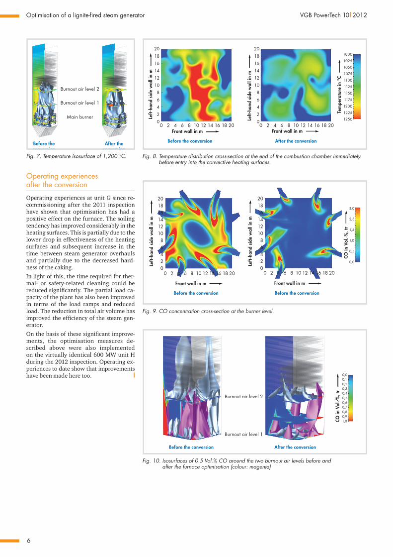
This trend is also confirmed by comparing the axial temperature profiles above the boiler level. F i g u r e 7 shows the tem-perature isosurface of 1,200 °C in grey. It is clear to see that this temperature isosur-face reaches far into the convective heating surfaces in the original construction. Fol-lowing the conversion, this temperature isosurface ends below the heating surfaces. F i g u r e 8 shows the temperature distri-bution cross-section at the end of the com-bustion chamber immediately before entry into the convective heating surfaces. Fol-lowing the conversion, a significant drop in the high temperatures at the end of the combustion chamber can be seen. This is a result of the fast fuel conversion in the burner belt.
A further factor in fuel conversion is the CO content. F i g u r e 9 shows the CO concen-tration cross-section at the burner level. A significant drop in the CO concentration following the conversion can be seen here.
The increased temperature in the burner belt (Figure 6), the drop in the high tem-peratures at the end of the combustion chamber (Figures 7 and 8) and the simul-taneous drop in the CO concentration in the burner belt (Figure 9) clearly confirm that the burner conversion has resulted in early ignition and considerably improved fuel conversion in the lower area of the combustion chamber.
F i g u r e 1 0 shows the isosurfaces of 0.5 Vol.% CO around the two burnout air levels before and after the furnace opti-misation (colour: magenta). Here too it is clear that the optimised burnout air vol-umes and speeds have resulted in an im-proved mixture of the combustion air with considerably more effective residual com-bustion. This is reflected in the lower CO content in both burnout air levels.
Fig. 4. The new burner array and the new burner setup.
1
Front wall
2
3
4
5
6
7 8 9 10
11
12
13
14
1516
Burnout air level 2
1
Front wall
3
5
7 9
11
13
15
Burnout air level 1
6
8 10
12
2 16
14
4
60 m/s; 1/6 mges
60 m/s; 1/12 mges
Left-
hand
sid
e w
all
Left-
hand
sid
e w
all
60 m/s; 1/6 mges
45 m/s; 1/12 mges
Fig. 5. The new nozzle arrangement on the two burnout air levels along with the corresponding air discharge speeds.
20181614121086420
0 2 4 6 8 10 12 14 16 18 20
20181614121086420
0 2 4 6 8 10 12 14 16 18 20
Before the Front wall in m
Left-
hand
side
wal
l in
m
Left-
hand
side
wal
l in
m
Front wall in m
Before the conversion After the conversion
Fig. 6. Temperature distribution cross-section near to the upper dust finger in the lower burner level.
6
Optimisation of a lignite-fired steam generator VGB PowerTech 10 l 2012
Operating experiences after the conversion
Operating experiences at unit G since re-commissioning after the 2011 inspection have shown that optimisation has had a positive effect on the furnace. The soiling tendency has improved considerably in the heating surfaces. This is partially due to the lower drop in effectiveness of the heating surfaces and subsequent increase in the time between steam generator overhauls and partially due to the decreased hard-ness of the caking.In light of this, the time required for ther-mal- or safety-related cleaning could be reduced significantly. The partial load ca-pacity of the plant has also been improved in terms of the load ramps and reduced load. The reduction in total air volume has improved the efficiency of the steam gen-erator.On the basis of these significant improve-ments, the optimisation measures de-scribed above were also implemented on the virtually identical 600 MW unit H during the 2012 inspection. Operating ex-periences to date show that improvements have been made here too. l
Burnout air level 2
Burnout air level 1
Main burner
Before theconversion
After theconversion
Fig. 7. Temperature isosurface of 1,200 °C.
1000
1025
1050
1075
1100
1125
1150
1175
1200
1225
1250
20181614121086420
0 2 4 6 8 10 12 14 16 18 20 0 2 4 6 8 10 12 14 16 18 20
Left-
hand
side
wal
l in
m
Left-
hand
side
wal
l in
m
Front wall in m Front wall in m
Tem
pera
ture
in °C
20181614121086420
Before the conversion After the conversion
Fig. 8. Temperature distribution cross-section at the end of the combustion chamber immediately before entry into the convective heating surfaces.
20181614121086420
0 2 4 6 8 10 12 14 16 18 20
Front wall in m
Left-
hand
side
wal
l in
m
20181614121086420
0 2 4 6 8 10 12 14 16 18 20
Front wall in m
Left-
hand
side
wal
l in
m
CO in
Vol
.-%, t
r
3,0
2,5
1,5
1,0
0,5
0,0
Before the conversion Before the conversion
Fig. 9. CO concentration cross-section at the burner level.
0,00,10,20,30,40,50,60,70,80,91,0
Burnout air level 2
Burnout air level 1
Before the conversion After the conversion
CO in
Vol
.-%, t
r
Fig. 10. Isosurfaces of 0.5 Vol.% CO around the two burnout air levels before and after the furnace optimisation (colour: magenta)


![V.S LIGNITE POWER Pvt. Ltd [Gurha East Lignite Mine (1 MPTA)] · V.S LIGNITE POWER Pvt. Ltd [Gurha East Lignite Mine (1 MPTA)] AT VILLAGE-GURHA, KOLAYAT, BIKANER, ... Embankment has](https://img.pdfslide.us/doc/110x75/5e8c64539924dc7ac37938bd/vs-lignite-power-pvt-ltd-gurha-east-lignite-mine-1-mpta-vs-lignite-power.jpg)