Embed Size (px)
Citation preview

Furious Build Notes By McMaven
1
Furious Build Notes
By McMaven
Furious Build Notes By McMaven
2
Contents
Contents Contents ........................................................................................................................................................ 2
Table of Figures ............................................................................................................................................. 3
1 Overview ............................................................................................................................................... 4
2 Parts list ................................................................................................................................................. 6
2.1 Summary ....................................................................................................................................... 6
2.2 Details ........................................................................................................................................... 6
3 Components .......................................................................................................................................... 8
3.1 L1 ................................................................................................................................................... 8
3.2 L2 Layer Lower ............................................................................................................................ 11
3.2.1 To assemble the Upper L2 Assembly .................................................................................. 12
3.3 L2 Layer Upper ............................................................................................................................ 15
3.4 L3 ................................................................................................................................................. 15
3.5 Base ............................................................................................................................................. 16
3.6 Base Driver .................................................................................................................................. 18
4 Final Assembly..................................................................................................................................... 19
5 The Stepper Motor .............................................................................................................................. 20
6 Sources ................................................................................................................................................ 21
7 Escape Wheel ...................................................................................................................................... 23
7.1 Getting it to Tick .......................................................................................................................... 24
8 STL Files ............................................................................................................................................... 26
9 Other Stuff .......................................................................................................................................... 28
9.1 Some notes on gluing PLA… ........................................................................................................ 28
10 Release Notes.................................................................................................................................. 30
Furious Build Notes By McMaven
3
Table of Figures Figure 1: L1 Assembly Components ............................................................................................................ 10
Figure 2: Torque Spring ............................................................................................................................... 12
Figure 3: L2 Layer Lower Assembly Components ....................................................................................... 14
Figure 4: L2 Upper Assembly Components ................................................................................................. 15
Figure 5: L3 Assembly Components ............................................................................................................ 16
Figure 6: Base Assembly Components ........................................................................................................ 17
Figure 7: Base Driver Assembly Components ............................................................................................. 18
Figure 8: Schematics ................................................................................................................................... 20
Figure 9: Balance Wheel to Fork Alignment ............................................................................................... 24
Furious Build Notes By McMaven
4
1 Overview I modeled this design after a Jacob and Co. Twin Turbo Furious, which they offer in several of their high-
end watches. I spent many hours looking at this video
https://www.youtube.com/watch?time_continue=2&v=n4DxzTQBTSM .
Similar to the Gyrotourbillon and the Triple Axis, I tried to make the model an accurate (scaled up)
version of the original Furious mechanism. I printed the screws to scale and used them as caps to cover
the 2mm screws that actually hold it together.
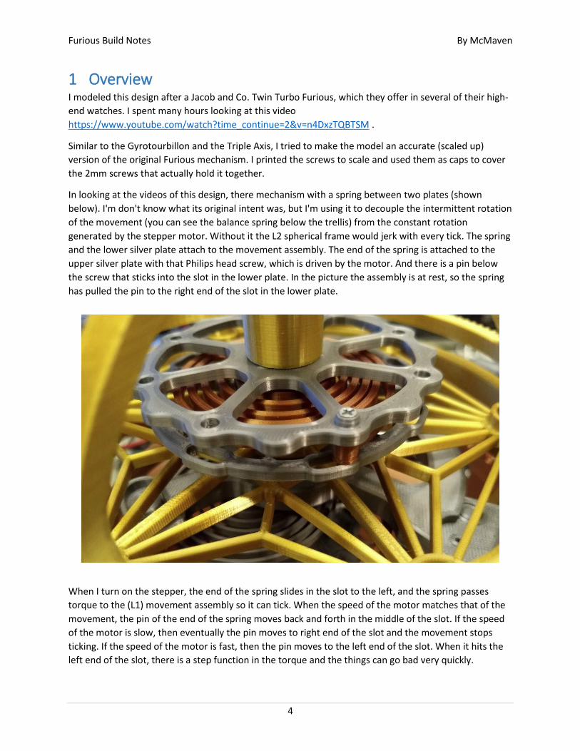
In looking at the videos of this design, there mechanism with a spring between two plates (shown
below). I'm don't know what its original intent was, but I'm using it to decouple the intermittent rotation
of the movement (you can see the balance spring below the trellis) from the constant rotation
generated by the stepper motor. Without it the L2 spherical frame would jerk with every tick. The spring
and the lower silver plate attach to the movement assembly. The end of the spring is attached to the
upper silver plate with that Philips head screw, which is driven by the motor. And there is a pin below
the screw that sticks into the slot in the lower plate. In the picture the assembly is at rest, so the spring
has pulled the pin to the right end of the slot in the lower plate.
When I turn on the stepper, the end of the spring slides in the slot to the left, and the spring passes
torque to the (L1) movement assembly so it can tick. When the speed of the motor matches that of the
movement, the pin of the end of the spring moves back and forth in the middle of the slot. If the speed
of the motor is slow, then eventually the pin moves to right end of the slot and the movement stops
ticking. If the speed of the motor is fast, then the pin moves to the left end of the slot. When it hits the
left end of the slot, there is a step function in the torque and the things can go bad very quickly.
Furious Build Notes By McMaven
5
This is because there is a torque overload when the end of the slot is hit, the torque overload passes too
much energy to the balance wheel (sort of kicking it) causing to swing further, which reduces the tick
frequency and average rotation rate of the movement assembly. The symptoms are that the movement
suddenly starts ticking very loudly, and the movement quickly binds. The sudden drop in the rotation
rate of movement aggravates the overload condition, which if ignored can break shafts or teeth of
gears. The one time I didn't stop the motor in time, the main shaft sticking out of the L1 Frame Bridge
broke.
I can watch the watch the position of the pin in the slot as it goes around, and tweak the motor speed
to keep it centered. The problem is that there is a huge delay in the response time to changes in motor
speed, so it's easy to over correct and lose control.
The code using sets the initial speed very low, so when I turn on the stepper, it starts at a really slow
rotation rate and this design needs a much faster rate. So I have to crank the shaft encoder like mad to
get it up to the speed, and at the same time I bump the balance wheel to make sure it doesn't hang and
break some gear teeth or something else. So for all practical purposes, you have to kick start it like an
old hit-or-miss engine, then carefully tend it to keep it running. I actually found it sort of a challenging to
find the speed sweet spot. So I decided to post the design as is, explain the issues, and see if anyone
comes up with a solution.
Other learnings...
At one point I squeezed the outer edges of the L2 Upper and Lower Bodies together too hard, and I
broke the shaft sticking out of the L1 Frame Base. My solution to this and the L1 Frame Bridge shaft
breaking was to design a 3mm hole in the center of each shaft, that I could slip a 3mm steel rod into.
This was also my first experience with 'silk' PLA filaments, and there was learning curve. Using the same
settings that I have been using forever for regular PLA, the first layer didn't want to stick to the print
bed, and I found that it has relatively poor inter-layer adhesion. To address the layer 1 problem I tried
changing the print bed temp from 60 to 70 C°, but it did not seem to be very effective. What worked was
a lower the Z height on the first layer to get a lot more squash to it. To address the inter-layer adhesion
problem, I turned up the extruder temperature 10, but again this did not make a big difference,
however the parts seemed a little stronger when I changed the perimeter layer count from 2 to 3.
A lot of people complain because silk filaments clog their nozzles. I printed all the parts for this design
without a clog, however shortly after I switched to normal PLA to print the base I got my first clog ever,
and that's with over 2000 hours of print time on the same 0.4mm brass nozzle. I used it as an excuse to
finally put a new nozzle in. I have no idea if the silk PLA had anything to do with it, but it seemed like a
weird coincidence.
This model is LARGE, at over 200mm in diameter. And it's powered it with a 2 Amp USB power supply.
And a real-time video. https://youtu.be/Imm3mrR06tc
Furious Build Notes By McMaven
6
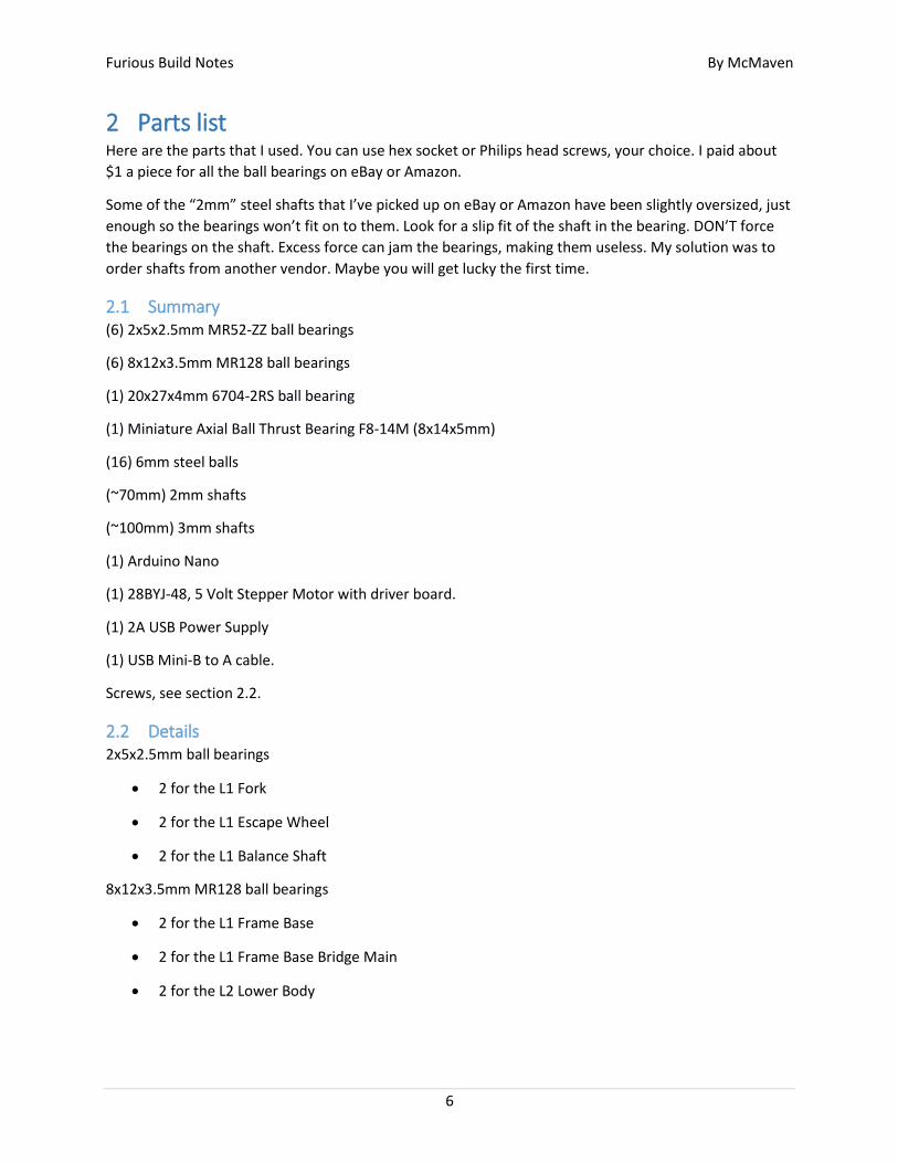
2 Parts list Here are the parts that I used. You can use hex socket or Philips head screws, your choice. I paid about
$1 a piece for all the ball bearings on eBay or Amazon.
Some of the “2mm” steel shafts that I’ve picked up on eBay or Amazon have been slightly oversized, just
enough so the bearings won’t fit on to them. Look for a slip fit of the shaft in the bearing. DON’T force
the bearings on the shaft. Excess force can jam the bearings, making them useless. My solution was to
order shafts from another vendor. Maybe you will get lucky the first time.
2.1 Summary (6) 2x5x2.5mm MR52-ZZ ball bearings
(6) 8x12x3.5mm MR128 ball bearings
(1) 20x27x4mm 6704-2RS ball bearing
(1) Miniature Axial Ball Thrust Bearing F8-14M (8x14x5mm)
(16) 6mm steel balls
(~70mm) 2mm shafts
(~100mm) 3mm shafts
(1) Arduino Nano
(1) 28BYJ-48, 5 Volt Stepper Motor with driver board.
(1) 2A USB Power Supply
(1) USB Mini-B to A cable.
Screws, see section 2.2.
2.2 Details 2x5x2.5mm ball bearings
2 for the L1 Fork
2 for the L1 Escape Wheel
2 for the L1 Balance Shaft
8x12x3.5mm MR128 ball bearings
2 for the L1 Frame Base
2 for the L1 Frame Base Bridge Main
2 for the L2 Lower Body
Furious Build Notes By McMaven
7
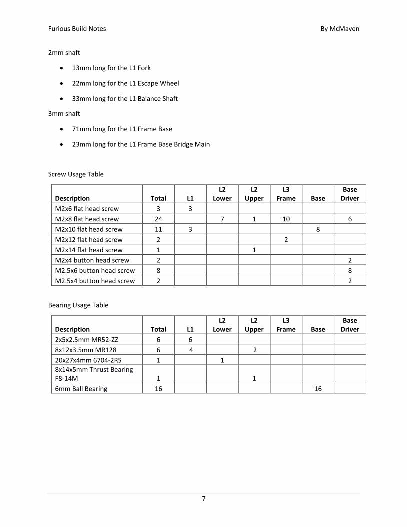
2mm shaft
13mm long for the L1 Fork
22mm long for the L1 Escape Wheel
33mm long for the L1 Balance Shaft
3mm shaft
71mm long for the L1 Frame Base
23mm long for the L1 Frame Base Bridge Main
Screw Usage Table
Description Total L1 L2
Lower L2
Upper L3
Frame Base Base
Driver
M2x6 flat head screw 3 3 M2x8 flat head screw 24 7 1 10 6
M2x10 flat head screw 11 3 8 M2x12 flat head screw 2 2 M2x14 flat head screw 1 1 M2x4 button head screw 2 2
M2.5x6 button head screw 8 8
M2.5x4 button head screw 2 2
Bearing Usage Table
Description Total L1 L2
Lower L2
Upper L3
Frame Base Base
Driver
2x5x2.5mm MR52-ZZ 6 6 8x12x3.5mm MR128 6 4 2 20x27x4mm 6704-2RS 1 1 8x14x5mm Thrust Bearing F8-14M 1 1 6mm Ball Bearing 16 16
Furious Build Notes By McMaven
8
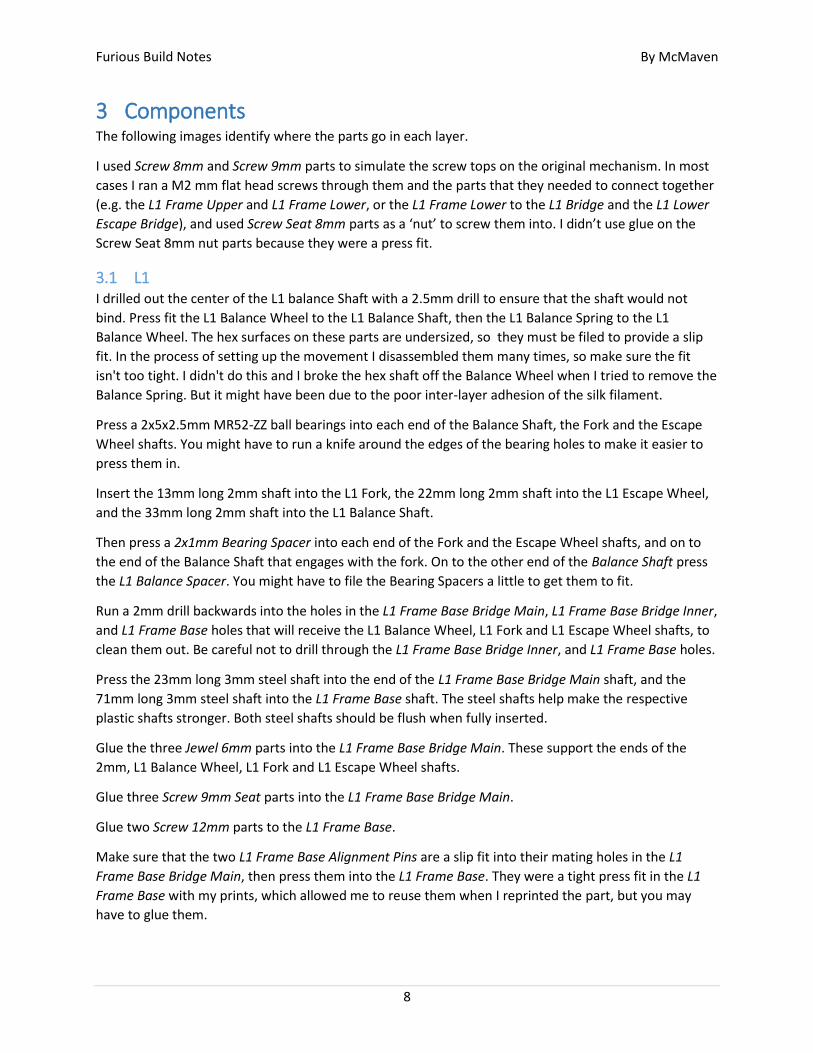
3 Components The following images identify where the parts go in each layer.
I used Screw 8mm and Screw 9mm parts to simulate the screw tops on the original mechanism. In most
cases I ran a M2 mm flat head screws through them and the parts that they needed to connect together
(e.g. the L1 Frame Upper and L1 Frame Lower, or the L1 Frame Lower to the L1 Bridge and the L1 Lower
Escape Bridge), and used Screw Seat 8mm parts as a ‘nut’ to screw them into. I didn’t use glue on the
Screw Seat 8mm nut parts because they were a press fit.
3.1 L1 I drilled out the center of the L1 balance Shaft with a 2.5mm drill to ensure that the shaft would not
bind. Press fit the L1 Balance Wheel to the L1 Balance Shaft, then the L1 Balance Spring to the L1
Balance Wheel. The hex surfaces on these parts are undersized, so they must be filed to provide a slip
fit. In the process of setting up the movement I disassembled them many times, so make sure the fit
isn't too tight. I didn't do this and I broke the hex shaft off the Balance Wheel when I tried to remove the
Balance Spring. But it might have been due to the poor inter-layer adhesion of the silk filament.
Press a 2x5x2.5mm MR52-ZZ ball bearings into each end of the Balance Shaft, the Fork and the Escape
Wheel shafts. You might have to run a knife around the edges of the bearing holes to make it easier to
press them in.
Insert the 13mm long 2mm shaft into the L1 Fork, the 22mm long 2mm shaft into the L1 Escape Wheel,
and the 33mm long 2mm shaft into the L1 Balance Shaft.
Then press a 2x1mm Bearing Spacer into each end of the Fork and the Escape Wheel shafts, and on to
the end of the Balance Shaft that engages with the fork. On to the other end of the Balance Shaft press
the L1 Balance Spacer. You might have to file the Bearing Spacers a little to get them to fit.
Run a 2mm drill backwards into the holes in the L1 Frame Base Bridge Main, L1 Frame Base Bridge Inner,
and L1 Frame Base holes that will receive the L1 Balance Wheel, L1 Fork and L1 Escape Wheel shafts, to
clean them out. Be careful not to drill through the L1 Frame Base Bridge Inner, and L1 Frame Base holes.
Press the 23mm long 3mm steel shaft into the end of the L1 Frame Base Bridge Main shaft, and the
71mm long 3mm steel shaft into the L1 Frame Base shaft. The steel shafts help make the respective
plastic shafts stronger. Both steel shafts should be flush when fully inserted.
Glue the three Jewel 6mm parts into the L1 Frame Base Bridge Main. These support the ends of the
2mm, L1 Balance Wheel, L1 Fork and L1 Escape Wheel shafts.
Glue three Screw 9mm Seat parts into the L1 Frame Base Bridge Main.
Glue two Screw 12mm parts to the L1 Frame Base.
Make sure that the two L1 Frame Base Alignment Pins are a slip fit into their mating holes in the L1
Frame Base Bridge Main, then press them into the L1 Frame Base. They were a tight press fit in the L1
Frame Base with my prints, which allowed me to reuse them when I reprinted the part, but you may
have to glue them.

Furious Build Notes By McMaven
9
Fit the Fork and the Escape Wheel with their shafts to the L1 Frame Base Bridge Main, then use three
M2x6mm flat head screws to attach the L1 Frame Base Bridge Inner to the L1 Frame Base Bridge Main.
At this point check that the surfaces of the L1 Frame Base Bridge Inner and L1 Frame Base Bridge Main
are parallel. If one of the 2mm shafts is slightly too long, it can cause the L1 Frame Base Bridge Inner to
bend away from the L1 Frame Base Bridge Main.
Fit the Balance Wheel assembly with its 2mm shaft to the L1 Frame Base Bridge Main, press the
assembly on to the L1 Frame Base and use two M2x10mm flat head screws to attach them together.
In the slotted hole of the L1 Frame Base, insert the L1 Balance Spring End Mount, center it in the slot
and orient it with its tab facing away from the end of the Balance Spring. Then through a Screw 9mm w
screw hole part use a M2x10mm flat head screw to hold them together. Now press the end of the
Balance Spring into the L1 Balance Spring End Mount.
Press two Screw 7mm End Cap parts into the L1 Frame Base Bridge Main part to cover the screws. Note
that you may want to hold off on this step until after you are sure that the L1 Assembly is tuned. They
can be a pain to get out if you need to disassemble the L1 Assembly.
Slip a 8x12x3.5mm MR128 ball bearing, the L1 Bearing Spacer Lower, and a second 8x12x3.5mm MR128
ball bearing, onto the L1 Frame Base Bridge Main shaft. Then do the same thing for the L1 Frame Base
but use the L1 Bearing Spacer Upper.
Now the L1 Assembly is complete.
Furious Build Notes By McMaven
10
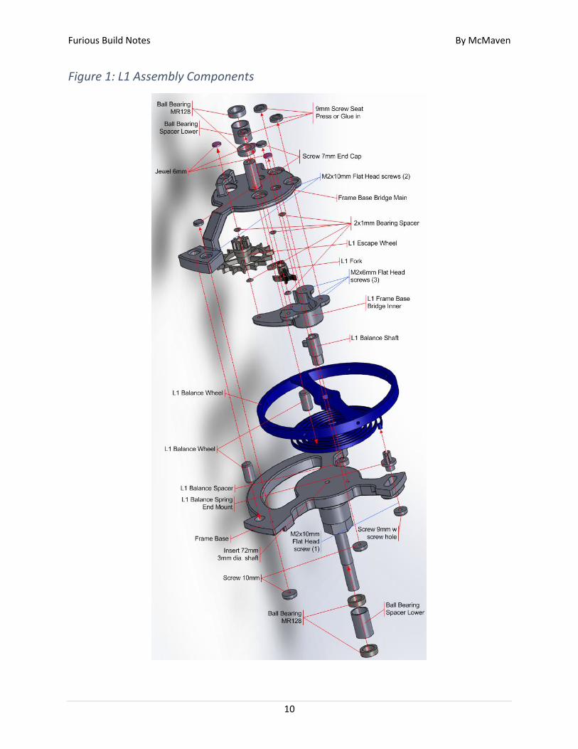
Figure 1: L1 Assembly Components
Furious Build Notes By McMaven
11
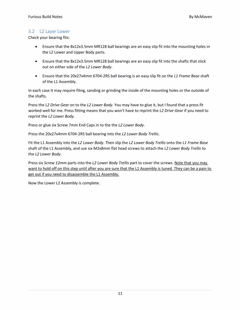
3.2 L2 Layer Lower Check your bearing fits:
Ensure that the 8x12x3.5mm MR128 ball bearings are an easy slip fit into the mounting holes in
the L2 Lower and Upper Body parts.
Ensure that the 8x12x3.5mm MR128 ball bearings are an easy slip fit into the shafts that stick
out on either side of the L2 Lower Body.
Ensure that the 20x27x4mm 6704-2RS ball bearing is an easy slip fit on the L1 Frame Base shaft
of the L1 Assembly.
In each case it may require filing, sanding or grinding the inside of the mounting holes or the outside of
the shafts.
Press the L2 Drive Gear on to the L2 Lower Body. You may have to glue it, but I found that a press fit
worked well for me. Press fitting means that you won't have to reprint the L2 Drive Gear if you need to
reprint the L2 Lower Body.
Press or glue six Screw 7mm End Caps in to the the L2 Lower Body.
Press the 20x27x4mm 6704-2RS ball bearing into the L2 Lower Body Trellis.
Fit the L1 Assembly into the L2 Lower Body. Then slip the L2 Lower Body Trellis onto the L1 Frame Base
shaft of the L1 Assembly, and use six M2x8mm flat head screws to attach the L2 Lower Body Trellis to
the L2 Lower Body.
Press six Screw 12mm parts into the L2 Lower Body Trellis part to cover the screws. Note that you may
want to hold off on this step until after you are sure that the L1 Assembly is tuned. They can be a pain to
get out if you need to disassemble the L1 Assembly.
Now the Lower L2 Assembly is complete.
Furious Build Notes By McMaven
12
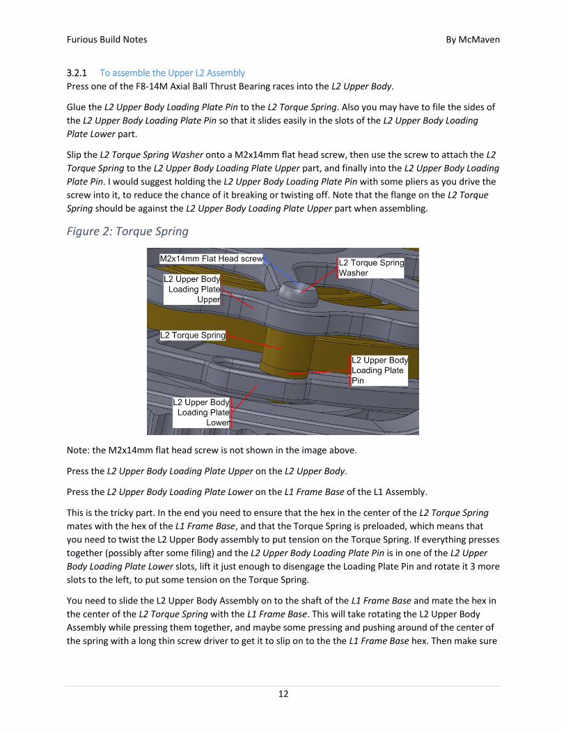
3.2.1 To assemble the Upper L2 Assembly
Press one of the F8-14M Axial Ball Thrust Bearing races into the L2 Upper Body.
Glue the L2 Upper Body Loading Plate Pin to the L2 Torque Spring. Also you may have to file the sides of
the L2 Upper Body Loading Plate Pin so that it slides easily in the slots of the L2 Upper Body Loading
Plate Lower part.
Slip the L2 Torque Spring Washer onto a M2x14mm flat head screw, then use the screw to attach the L2
Torque Spring to the L2 Upper Body Loading Plate Upper part, and finally into the L2 Upper Body Loading
Plate Pin. I would suggest holding the L2 Upper Body Loading Plate Pin with some pliers as you drive the
screw into it, to reduce the chance of it breaking or twisting off. Note that the flange on the L2 Torque
Spring should be against the L2 Upper Body Loading Plate Upper part when assembling.
Figure 2: Torque Spring
Note: the M2x14mm flat head screw is not shown in the image above.
Press the L2 Upper Body Loading Plate Upper on the L2 Upper Body.
Press the L2 Upper Body Loading Plate Lower on the L1 Frame Base of the L1 Assembly.
This is the tricky part. In the end you need to ensure that the hex in the center of the L2 Torque Spring
mates with the hex of the L1 Frame Base, and that the Torque Spring is preloaded, which means that
you need to twist the L2 Upper Body assembly to put tension on the Torque Spring. If everything presses
together (possibly after some filing) and the L2 Upper Body Loading Plate Pin is in one of the L2 Upper
Body Loading Plate Lower slots, lift it just enough to disengage the Loading Plate Pin and rotate it 3 more
slots to the left, to put some tension on the Torque Spring.
You need to slide the L2 Upper Body Assembly on to the shaft of the L1 Frame Base and mate the hex in
the center of the L2 Torque Spring with the L1 Frame Base. This will take rotating the L2 Upper Body
Assembly while pressing them together, and maybe some pressing and pushing around of the center of
the spring with a long thin screw driver to get it to slip on to the the L1 Frame Base hex. Then make sure

Furious Build Notes By McMaven
13
that the L2 Upper Body Loading Plate Pin is in one of the L2 Upper Body Loading Plate Lower slots and
the Torque Spring is preloaded, as described above.
When properly assembled, the upper and lower L2 assemblies should rotate with respect to each other,
the amount of rotation between them should be limited by the L2 Upper Body Loading Plate Lower slot
and the L2 Upper Body Loading Plate Pin, and the Torque Spring should pull the Loading Plate Pin back
to the right end of the slot (as shown above) when you let go of the L2 Upper Body Assembly.
Furious Build Notes By McMaven
14
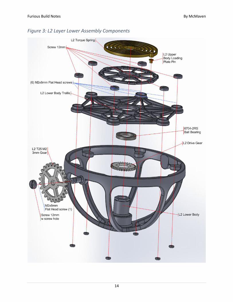
Figure 3: L2 Layer Lower Assembly Components
Furious Build Notes By McMaven
15
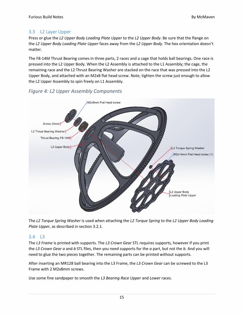
3.3 L2 Layer Upper Press or glue the L2 Upper Body Loading Plate Upper to the L2 Upper Body. Be sure that the flange on
the L2 Upper Body Loading Plate Upper faces away from the L2 Upper Body. The hex orientation doesn’t
matter.
The F8-14M Thrust Bearing comes in three parts, 2 races and a cage that holds ball bearings. One race is
pressed into the L2 Upper Body. When the L2 Assembly is attached to the L1 Assembly; the cage, the
remaining race and the L2 Thrust Bearing Washer are stacked on the race that was pressed into the L2
Upper Body, and attached with an M2x8 flat head screw. Note, tighten the screw just enough to allow
the L2 Upper Assembly to spin freely on L1 Assembly.
Figure 4: L2 Upper Assembly Components
The L2 Torque Spring Washer is used when attaching the L2 Torque Spring to the L2 Upper Body Loading
Plate Upper, as described in section 3.2.1.
3.4 L3 The L3 Frame is printed with supports. The L3 Crown Gear STL requires supports, however if you print
the L3 Crown Gear a and b STL files, then you need supports for the a part, but not the b. And you will
need to glue the two pieces together. The remaining parts can be printed without supports.
After inserting an MR128 ball bearing into the L3 Frame, the L3 Crown Gear can be screwed to the L3
Frame with 2 M2x8mm screws.
Use some fine sandpaper to smooth the L3 Bearing Race Upper and Lower races.
Furious Build Notes By McMaven
16
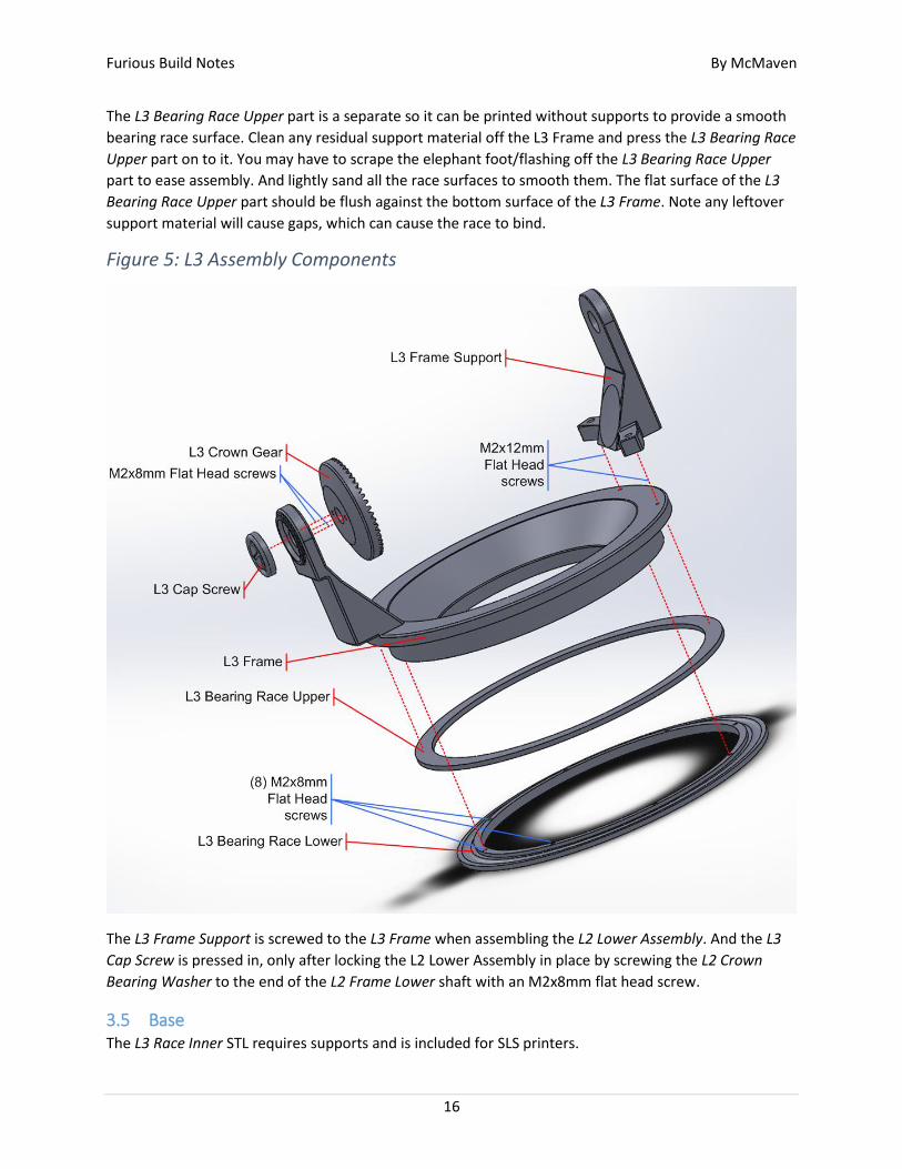
The L3 Bearing Race Upper part is a separate so it can be printed without supports to provide a smooth
bearing race surface. Clean any residual support material off the L3 Frame and press the L3 Bearing Race
Upper part on to it. You may have to scrape the elephant foot/flashing off the L3 Bearing Race Upper
part to ease assembly. And lightly sand all the race surfaces to smooth them. The flat surface of the L3
Bearing Race Upper part should be flush against the bottom surface of the L3 Frame. Note any leftover
support material will cause gaps, which can cause the race to bind.
Figure 5: L3 Assembly Components
The L3 Frame Support is screwed to the L3 Frame when assembling the L2 Lower Assembly. And the L3
Cap Screw is pressed in, only after locking the L2 Lower Assembly in place by screwing the L2 Crown
Bearing Washer to the end of the L2 Frame Lower shaft with an M2x8mm flat head screw.
3.5 Base The L3 Race Inner STL requires supports and is included for SLS printers.
Furious Build Notes By McMaven
17
If you print the L3 Race Inner a and b STL files with the races facing up, then no supports are needed for
the prints, and you should get a smoother bearing race surface on both parts. However you will need to
glue the two pieces together. Make sure that the screw holes line up when you glue them together.
Glue them together with some ‘Acrylic Cement’ (see section Some notes on gluing PLA… below). This
stuff is super volatile and works in seconds. So make sure you are ready to align the parts before you
apply the glue.
Use some fine sandpaper to smooth the races.
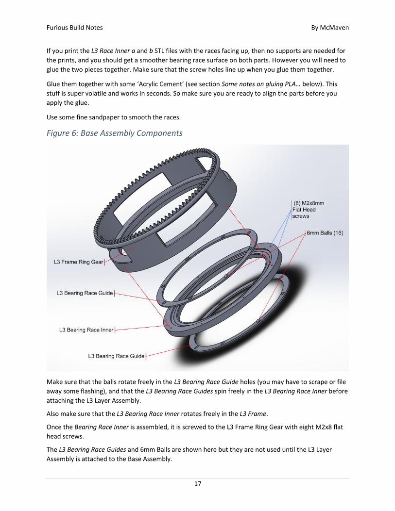
Figure 6: Base Assembly Components
Make sure that the balls rotate freely in the L3 Bearing Race Guide holes (you may have to scrape or file
away some flashing), and that the L3 Bearing Race Guides spin freely in the L3 Bearing Race Inner before
attaching the L3 Layer Assembly.
Also make sure that the L3 Bearing Race Inner rotates freely in the L3 Frame.
Once the Bearing Race Inner is assembled, it is screwed to the L3 Frame Ring Gear with eight M2x8 flat
head screws.
The L3 Bearing Race Guides and 6mm Balls are shown here but they are not used until the L3 Layer
Assembly is attached to the Base Assembly.
Furious Build Notes By McMaven
18
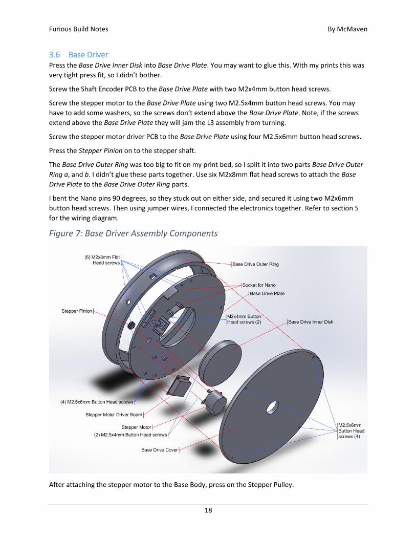
3.6 Base Driver Press the Base Drive Inner Disk into Base Drive Plate. You may want to glue this. With my prints this was
very tight press fit, so I didn’t bother.
Screw the Shaft Encoder PCB to the Base Drive Plate with two M2x4mm button head screws.
Screw the stepper motor to the Base Drive Plate using two M2.5x4mm button head screws. You may
have to add some washers, so the screws don’t extend above the Base Drive Plate. Note, if the screws
extend above the Base Drive Plate they will jam the L3 assembly from turning.
Screw the stepper motor driver PCB to the Base Drive Plate using four M2.5x6mm button head screws.
Press the Stepper Pinion on to the stepper shaft.
The Base Drive Outer Ring was too big to fit on my print bed, so I split it into two parts Base Drive Outer
Ring a, and b. I didn’t glue these parts together. Use six M2x8mm flat head screws to attach the Base
Drive Plate to the Base Drive Outer Ring parts.
I bent the Nano pins 90 degrees, so they stuck out on either side, and secured it using two M2x6mm
button head screws. Then using jumper wires, I connected the electronics together. Refer to section 5
for the wiring diagram.
Figure 7: Base Driver Assembly Components
After attaching the stepper motor to the Base Body, press on the Stepper Pulley.
Furious Build Notes By McMaven
19
4 Final Assembly Press a MR128 ball bearing into the L3 Frame Support, then slide the L3 Frame Support onto the L2
Assembly L2 Lower Body shaft with the hex end. Press the L2 T25 M2 3mm Gear onto the hex end of the
shaft and through a Screw 12mm w screw hole part, use a M2x8mm flat head screw to attach the gear
to the L2 Assembly.
Slide the other L2 Assembly L2 Lower Body shaft into the L3 Crown Gear and use two M2x12mm flat
head screws to attach the L3 Frame Support to the L3 Frame of the L3 Assembly.
To combine the Base and L3 Assemblies, I held the L3 Assembly upside down, laid a L3 Bearing Race
Guide on top of the L3 Bearing Race Upper part, inserted the eight 6mm balls. Then laid the L3 Bearing
Race Inner of the Base Assembly on top of it, and repeated the process of laying down the remaining L3
Bearing Race Guide on top of the L3 Bearing Race Inner part, inserted the eight 6mm balls, and used
eight 2Mx8mm flat head screws to hold everything together.
Now check that the L3 Assembly rotates freely in the Base Assembly. If it binds at some point, it may be
due to a gap between the L3 Bearing Race Upper part and the L3 Frame, as discussed above. You can
back off the screws a bit if the L3 assembly binds as it turns.
Screw the Base Drive Assembly to the Base Assembly using four M2x12mm flat head screws. You may
have to run a 4mm drill backwards down the hole, so that the screws drop in the holes freely.
Finally use four M2.5x6mm button head screws to attach the Base Drive Cover to the Base Drive Outer
Ring.
Furious Build Notes By McMaven
20
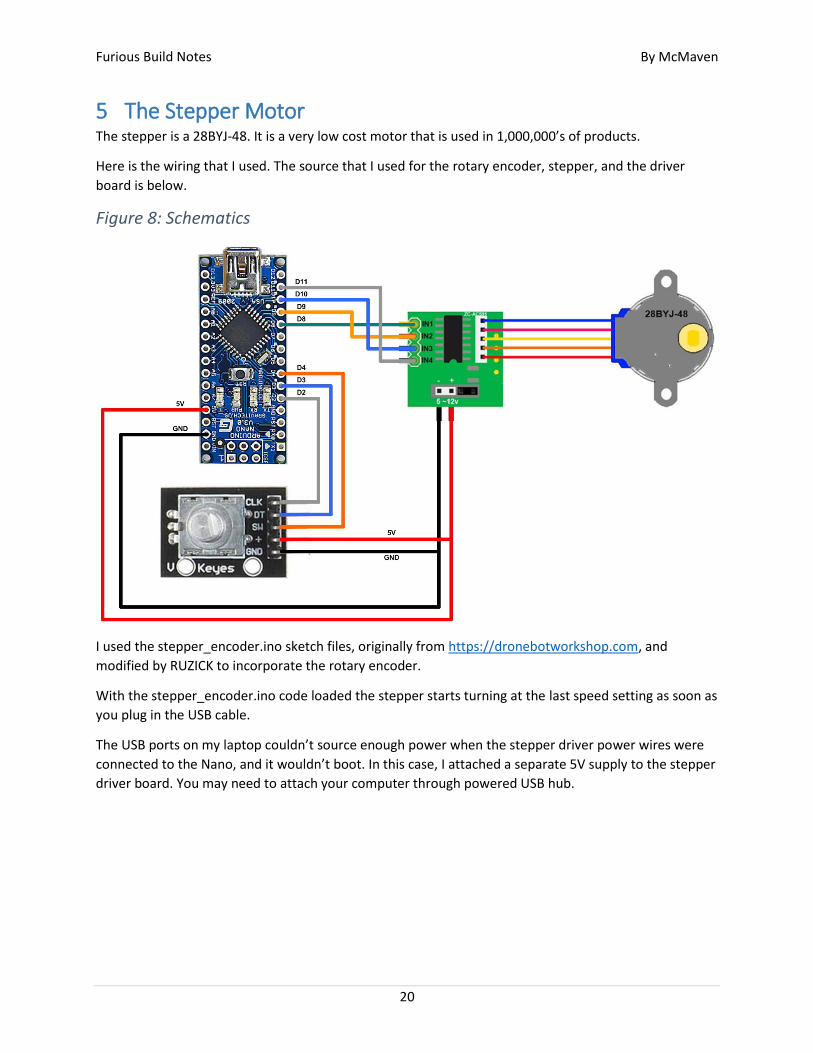
5 The Stepper Motor The stepper is a 28BYJ-48. It is a very low cost motor that is used in 1,000,000’s of products.
Here is the wiring that I used. The source that I used for the rotary encoder, stepper, and the driver
board is below.
Figure 8: Schematics
I used the stepper_encoder.ino sketch files, originally from https://dronebotworkshop.com, and
modified by RUZICK to incorporate the rotary encoder.
With the stepper_encoder.ino code loaded the stepper starts turning at the last speed setting as soon as
you plug in the USB cable.
The USB ports on my laptop couldn’t source enough power when the stepper driver power wires were
connected to the Nano, and it wouldn’t boot. In this case, I attached a separate 5V supply to the stepper
driver board. You may need to attach your computer through powered USB hub.
Furious Build Notes By McMaven
21
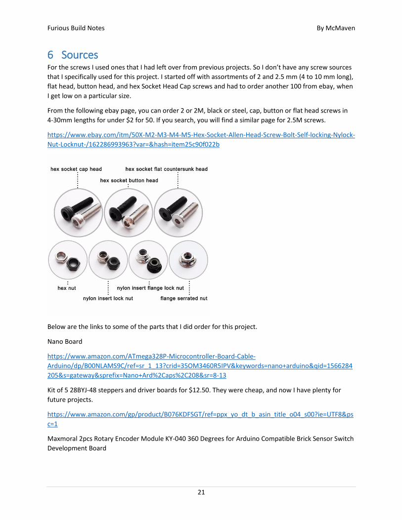
6 Sources For the screws I used ones that I had left over from previous projects. So I don’t have any screw sources
that I specifically used for this project. I started off with assortments of 2 and 2.5 mm (4 to 10 mm long),
flat head, button head, and hex Socket Head Cap screws and had to order another 100 from ebay, when
I get low on a particular size.
From the following ebay page, you can order 2 or 2M, black or steel, cap, button or flat head screws in
4-30mm lengths for under $2 for 50. If you search, you will find a similar page for 2.5M screws.
https://www.ebay.com/itm/50X-M2-M3-M4-M5-Hex-Socket-Allen-Head-Screw-Bolt-Self-locking-Nylock-
Nut-Locknut-/162286993963?var=&hash=item25c90f022b
Below are the links to some of the parts that I did order for this project.
Nano Board
https://www.amazon.com/ATmega328P-Microcontroller-Board-Cable-
Arduino/dp/B00NLAMS9C/ref=sr_1_13?crid=35OM3460R5IPV&keywords=nano+arduino&qid=1566284
205&s=gateway&sprefix=Nano+Ard%2Caps%2C208&sr=8-13
Kit of 5 28BYJ-48 steppers and driver boards for $12.50. They were cheap, and now I have plenty for
future projects.
https://www.amazon.com/gp/product/B076KDFSGT/ref=ppx_yo_dt_b_asin_title_o04_s00?ie=UTF8&ps
c=1
Maxmoral 2pcs Rotary Encoder Module KY-040 360 Degrees for Arduino Compatible Brick Sensor Switch
Development Board

Furious Build Notes By McMaven
22
https://www.amazon.com/Maxmoral-Encoder-Degrees-Compatible-
Development/dp/B07M631J1Q/ref=sr_1_13?crid=KSJ7Y7TJBM9X&keywords=arduino+rotary+encoder&
qid=1566284441&s=gateway&sprefix=Arduino+rotary+e%2Caps%2C201&sr=8-13
HATCHBOX PLA 3D Printer Filament, Dimensional Accuracy +/- 0.03 mm, 1 kg Spool, 1.75 mm,
Transparent Red
https://www.amazon.com/gp/product/B00M0CS68E/ref=ppx_yo_dt_b_asin_title_o05_s00?ie=UTF8&ps
c=1
2x5x2.5mm MR52-ZZ Precision Ball Bearings Chrome Steel, Metal Shield
https://www.amazon.com/gp/product/B00TVPSCVO/ref=ppx_yo_dt_b_asin_title_o06_s00?ie=UTF8&ps
c=1
20x27x4 Metal Shielded Bearing 6704-ZZ
https://www.amazon.com/gp/product/B00LN41BNW/ref=ppx_yo_dt_b_asin_title_o05_s00?ie=UTF8&p
sc=1
uxcell 10pcs MR128ZZ 8mmx12mmx3.5mm Double Shielded Miniature Deep Groove Ball Bearing
https://www.amazon.com/gp/product/B075CMJT1X/ref=ppx_yo_dt_b_asin_title_o05_s00?ie=UTF8&ps
c=1
Atoplee 4pcs Miniature Axial Ball Thrust Bearings F8-14M (8x14x5mm)
https://www.amazon.com/gp/product/B01EMZ24G6/ref=ppx_yo_dt_b_search_asin_title?ie=UTF8&psc
=1
6mm (0.236") Precision Chrome Steel Bearing Balls G25
https://www.amazon.com/PGN-0-236-Precision-Chrome-
Bearing/dp/B07DKSN46T/ref=sr_1_2_sspa?keywords=6mm+ball+bearing&qid=1557296488&s=gateway
&sr=8-2-spons&psc=1
Furious Build Notes By McMaven
23
7 Escape Wheel The trick to aligning the balance spring is to position the balance wheel so the Balance Wheel Post, that
engages with the Fork Pins, is pointing directly at the center of the Fork shaft. I refer to this position as
the ‘natural center position’ of the Balance Wheel. And the Fork Center Pin should be pointing directly
at the center of the Balance Wheel Shaft. See Figure 9.
Then, with the Balance Spring rotated to the position where it drops into the Balance Spring Adjuster
mount on the L1 Frame 3, push the hex center of the Balance Spring onto the hex of the Balance Wheel.
Then push the hex center of the Balance Wheel onto the hex of the Balance Shaft Note, you may have to
file the hex’s before you start to make this a snug slip fit. I didn’t glue the Balance Shaft or the Balance
Spring to the Balance Wheel, because the Balance Spring is the part most likely to fail, and I wanted to
be able to easily replace it.
When I was testing my L1 Assembly, the Balance Wheel was regularly hanging at the same angle. Using
the L1 Balance Spring Adjuster to rotate the Balance Spring so that the ‘natural center position’ of the
Balance was better aligned with the Fork shaft, and it made the problem go away.
After connecting the balance spring to the balance wheel and the tourbillon frame, the balance wheel
tab should point directly at the fork, when the balance wheel is at rest. See Figure 9.
It doesn’t really matter what angle the Balance wheel is at, relative to the L1 Balance Spring and the L1
Balance Shaft. But the L1 Balance Spring to L1 Balance Shaft relationship is critical.
Furious Build Notes By McMaven
24
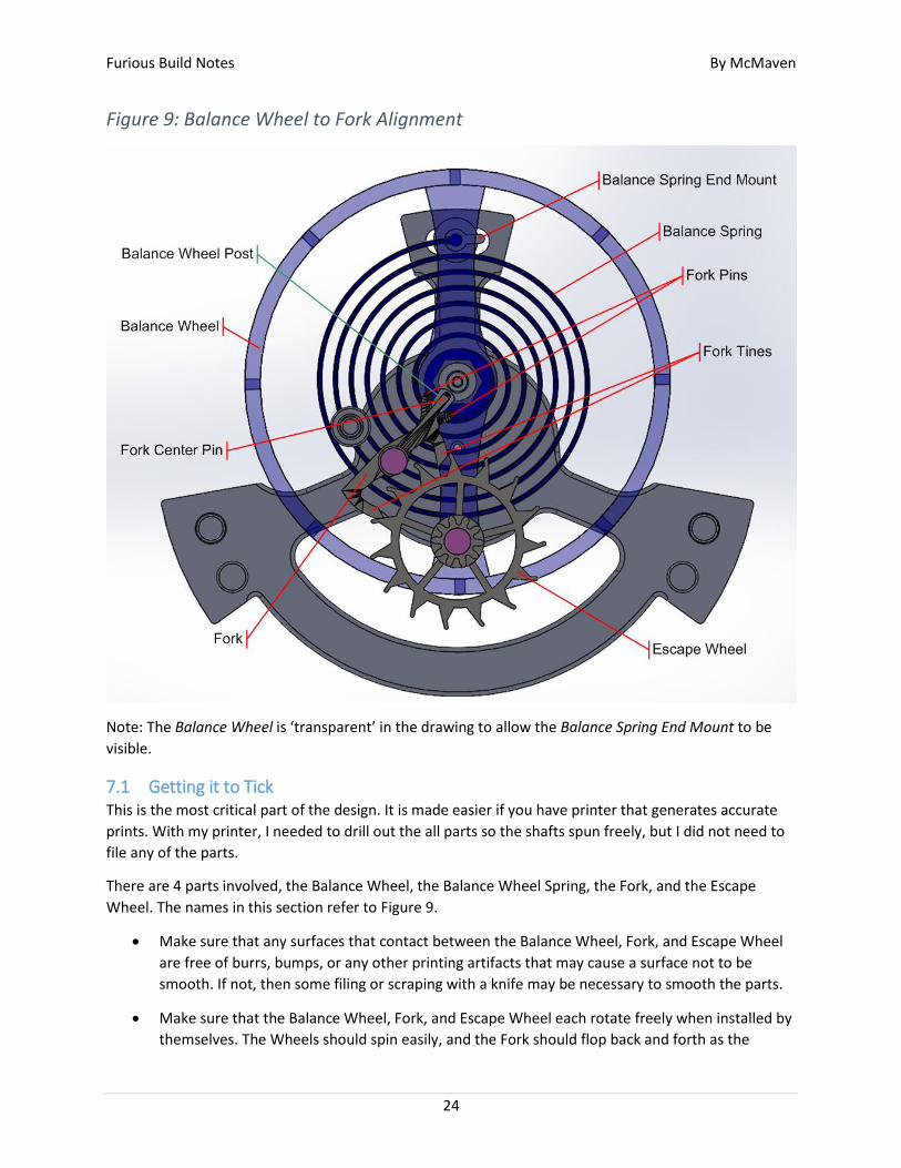
Figure 9: Balance Wheel to Fork Alignment
Note: The Balance Wheel is ‘transparent’ in the drawing to allow the Balance Spring End Mount to be
visible.
7.1 Getting it to Tick This is the most critical part of the design. It is made easier if you have printer that generates accurate
prints. With my printer, I needed to drill out the all parts so the shafts spun freely, but I did not need to
file any of the parts.
There are 4 parts involved, the Balance Wheel, the Balance Wheel Spring, the Fork, and the Escape
Wheel. The names in this section refer to Figure 9.
Make sure that any surfaces that contact between the Balance Wheel, Fork, and Escape Wheel
are free of burrs, bumps, or any other printing artifacts that may cause a surface not to be
smooth. If not, then some filing or scraping with a knife may be necessary to smooth the parts.
Make sure that the Balance Wheel, Fork, and Escape Wheel each rotate freely when installed by
themselves. The Wheels should spin easily, and the Fork should flop back and forth as the
Furious Build Notes By McMaven
25
assembly is rotated.
I ran a 2.5mm drill through the Fork and Escape Wheel shaft holes, and a 3.5mm drill through
the Escape Wheel shaft hole to ensure that any printing artifacts were cleared out of the
cavities.
Note: Run the drill backwards in plastic at first, otherwise it may auger in at some weird
angle and ruin the part. Once the drill is running smoothly backwards, reverse it to clear out
the plastic shards.
All bearings need to fully seated, so that their top surface is flush with the respective part. You
may need to pop them out and scratch out underneath them with a knife.
With just the Fork and Escape Wheel installed:
Turning the Escape Wheel backwards (clockwise in Figure 9), should cause the Fork to
snap back and forth easily.
And turning it counterclockwise should cause it snag against a Fork Tine. If the Fork
snaps back and forth a little, it is OK. But if it never snags the Balance wheel when rotated
counterclockwise, then the Fork Tines may be too short.
With just the Balance Wheel and Fork installed (No balance Spring), spinning the Balance Wheel
back and forth should cleanly engage the Fork. If there is any sign of a snag, or slowing down,
then inspect where the two parts are rubbing, and file the offending part lightly. It is easy to
take off too much. If you do, just print another part, and start again.
Depending on the direction the Balance Wheel is spinning, one of the Fork Pins and the Fork
Center Pin should slide along the surface of the Balance Wheel shaft, but not touch so much
that they slow the Balance Wheel down. The two contact points formed by the Fork Pin and the
Fork Center Pin act to hold the Fork at an angle where its Tines can snag/block an Escape Wheel
tooth.
When the Balance wheel is rotated in the opposite direction, the Balance Spring Post
engages with the Fork Pins to swing the Fork in to its opposite position. The swinging action
of the Fork causes the Escape Wheel to advance one tooth, and engage with the opposite
Fork Tine.
If there is any binding when the Fork swings, you will need to file the Center Pin a little
shorter.
When all the parts are assembled, a very light amount of torque on the Escape Wheel in the
counterclockwise direction should cause the fork to swing, and the Balance wheel to rotate.
Continuing to put torque on the Escape Wheel will cause the Fork to move to its opposite
position when the Balance Wheel swings back, due to the Balance Spring. As long as you put
consistent, light torque on the Escape Wheel, the assembly should continue to tick.
Furious Build Notes By McMaven
26
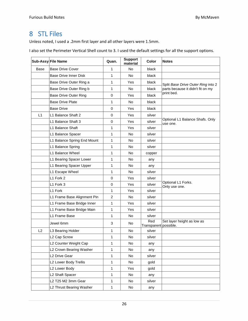
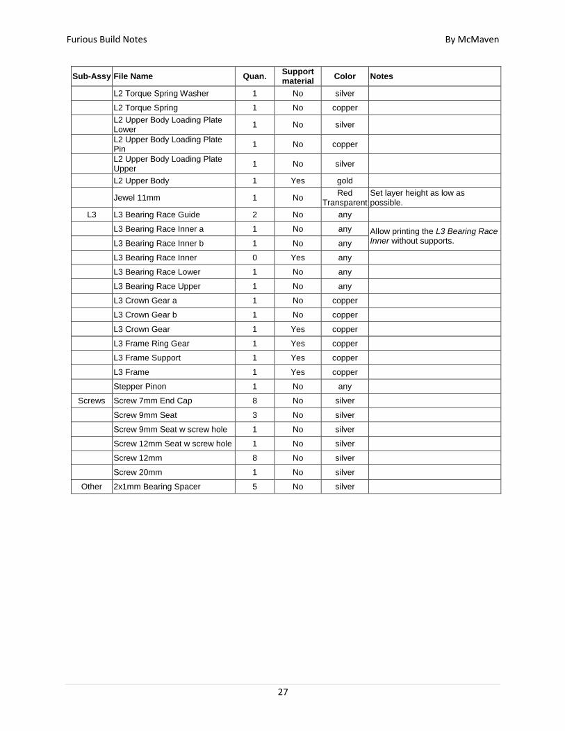
8 STL Files Unless noted, I used a .2mm first layer and all other layers were 1.5mm.
I also set the Perimeter Vertical Shell count to 3. I used the default settings for all the support options.
Sub-Assy File Name Quan. Support material
Color Notes
Base Base Drive Cover 1 No black
Base Drive Inner Disk 1 No black
Base Drive Outer Ring a 1 Yes black Split Base Drive Outer Ring into 2 parts because it didn't fit on my print bed.
Base Drive Outer Ring b 1 No black
Base Drive Outer Ring 0 Yes black
Base Drive Plate 1 No black
Base Drive 0 Yes black
L1 L1 Balance Shaft 2 0 Yes silver Optional L1 Balance Shafs. Only use one. L1 Balance Shaft 3 0 Yes silver
L1 Balance Shaft 1 Yes silver
L1 Balance Spacer 1 No silver
L1 Balance Spring End Mount 1 No silver
L1 Balance Spring 1 No silver
L1 Balance Wheel 1 No copper
L1 Bearing Spacer Lower 1 No any
L1 Bearing Spacer Upper 1 No any
L1 Escape Wheel 1 No silver
L1 Fork 2 0 Yes silver Optional L1 Forks. Only use one. L1 Fork 3 0 Yes silver
L1 Fork 1 Yes silver
L1 Frame Base Alignment Pin 2 No silver
L1 Frame Base Bridge Inner 1 Yes silver
L1 Frame Base Bridge Main 1 Yes silver
L1 Frame Base 1 No silver
Jewel 6mm 3 No Red
Transparent Set layer height as low as possible.
L2 L3 Bearing Holder 1 No silver
L2 Cap Screw 1 No silver
L2 Counter Weight Cap 1 No any
L2 Crown Bearing Washer 1 No any
L2 Drive Gear 1 No silver
L2 Lower Body Trellis 1 No gold
L2 Lower Body 1 Yes gold
L2 Shaft Spacer 1 No any
L2 T25 M2 3mm Gear 1 No silver
L2 Thrust Bearing Washer 1 No any
Furious Build Notes By McMaven
27
Sub-Assy File Name Quan. Support material
Color Notes
L2 Torque Spring Washer 1 No silver
L2 Torque Spring 1 No copper
L2 Upper Body Loading Plate Lower
1 No silver
L2 Upper Body Loading Plate Pin
1 No copper
L2 Upper Body Loading Plate Upper
1 No silver
L2 Upper Body 1 Yes gold
Jewel 11mm 1 No Red
Transparent Set layer height as low as possible.
L3 L3 Bearing Race Guide 2 No any
L3 Bearing Race Inner a 1 No any Allow printing the L3 Bearing Race Inner without supports. L3 Bearing Race Inner b 1 No any
L3 Bearing Race Inner 0 Yes any
L3 Bearing Race Lower 1 No any
L3 Bearing Race Upper 1 No any
L3 Crown Gear a 1 No copper
L3 Crown Gear b 1 No copper
L3 Crown Gear 1 Yes copper
L3 Frame Ring Gear 1 Yes copper
L3 Frame Support 1 Yes copper
L3 Frame 1 Yes copper
Stepper Pinon 1 No any
Screws Screw 7mm End Cap 8 No silver
Screw 9mm Seat 3 No silver
Screw 9mm Seat w screw hole 1 No silver
Screw 12mm Seat w screw hole 1 No silver
Screw 12mm 8 No silver
Screw 20mm 1 No silver
Other 2x1mm Bearing Spacer 5 No silver
Furious Build Notes By McMaven
28
9 Other Stuff
9.1 Some notes on gluing PLA… I purchased the Bottle Applicator and Acrylic Cement (also called ‘Acrylic Solvent’) from Tap Plastics.
Bottle Applicator:
https://www.tapplastics.com/product/supplies_tools/plastic_tools_supplies/hypo_type_solvent_cemen
t_applicator/409
Acrylic Cement:
https://www.tapplastics.com/product/repair_products/plastic_adhesives/tap_acrylic_cement/130
The web page says that the Acrylic Cement is for INDUSTRIAL USE ONLY. This is because it is made up of
Methylene Chloride (75-09-2), Trichloroethylene (79-01-6) and Methyl Methacrylate Monomer (80-62-
6). ONLY use in a well ventilated area!!! Not only does it smell bad, but inhaling it can hurt you. So treat
it with respect. Fortunately a little of it goes a long way, so the fumes from tiny drops are minimal. And
don’t forget that it is also flammable!
This is probably the most volatile stuff I’ve ever used. When it comes to evaporation, it makes alcohol
look like motor oil. There was an 1/8 inch of it in the bottom of the applicator and it was gone the next
day. And this was with the syringe top tightly screwed on, and the cap on it. Also, after 4 months of
sitting the garage a 4 oz. container of the stuff that was almost full when I put it on the shelf, was
empty! I found that the seal on the container is junk. After tightening as hard as I could, I could tip the
container and the stuff would still drip out. My solution, which has worked pretty well, was to store the
Cement container in a coffee can with a plastic cap. My theory was that, even with the leaky Cement
container, the solvent vapor pressure would equalize inside the coffee can, and slow the evaporation
process. But hold the coffee can away from you when you open it, otherwise you will get an eye
watering whiff of the stuff.
To fill the Bottle Applicator, just squeeze some air out of it, then stick the syringe into the bottle. It takes
a minute, but the stuff will be sucked into the bottle. I found that I never needed very much. An 1/8th of
an inch in the bottle, will go a long way. Besides anything you leave in the applicator will evaporate away
within a day.
With all this said, a friend said that Acetone was just as effective a cement for PLA. Being a cheapskate, I
will try it as soon as my current supply of Acrylic Cement is gone.
Also…
When using this Cement with the Bottle Applicator, its volatility comes into play. Normally you tip the
Applicator and give it a squeeze to get a single drop of cement to come out, then relax your grip to
cause an additional glue to be sucked back up the syringe. But because this stuff is so volatile, the heat
from your fingers causes it to expand, so instead of a single drop, the expansion of the cement inside the
bottle causes it to start dripping immediately. Even if you stop squeezing. This will flood your print with
glue if the syringe is against it and make a mess. I found the best way to get a single drop was to hold
the tip above a piece of cardboard, quickly tilt it to get a drop to come out, then tilt it back immediately,
but no so much that the cement reaches the end of the syringe inside the bottle. The ‘tilt back’ causes

Furious Build Notes By McMaven
29
the drop of cement to slide back to the working end of the syringe, without additional drips landing on
your work. Note: this only works if there is just a little solvent in the bottle.
Furious Build Notes By McMaven
30
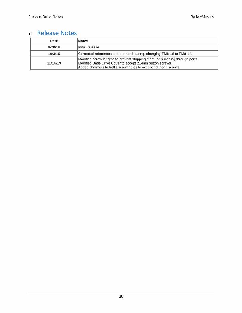
10 Release Notes
Date Notes
8/20/19 Initial release.
10/3/19 Corrected references to the thrust bearing, changing FM8-16 to FM8-14.
11/16/19 Modified screw lengths to prevent stripping them, or punching through parts. Modified Base Drive Cover to accept 2.5mm button screws. Added chamfers to trellis screw holes to accept flat head screws.