Embed Size (px)
Citation preview

Ultrasonic FlowmetersSITRANS FUP1010 IP67 Portable
Quick Start - January 2013
SITRANS FAnswers for industry.

___________________
FUP1010 IP67 Portable
___________________
___________________
___________________
___________________
1Introduction
2Installation
3Commissioning
SITRANS F
4Troubleshooting
Ultrasonic Flowmeters
AFUP1010 IP67 Portable Quick Start
Appendix
Operating Instructions
01/2013 CQO:QSG003 Revision 05
Siemens AG Industry Sector Postfach 48 48 90026 NÜRNBERG GERMANY
Order number: CQO:QSG003 Ⓟ 02/2013 Technical data subject to change
Copyright © Siemens AG 2013. All rights reserved
Legal information Warning notice system
This manual contains notices you have to observe in order to ensure your personal safety, as well as to prevent damage to property. The notices referring to your personal safety are highlighted in the manual by a safety alert symbol, notices referring only to property damage have no safety alert symbol. These notices shown below are graded according to the degree of danger.
DANGER indicates that death or severe personal injury will result if proper precautions are not taken.
WARNING indicates that death or severe personal injury may result if proper precautions are not taken.
CAUTION indicates that minor personal injury can result if proper precautions are not taken.
NOTICE indicates that property damage can result if proper precautions are not taken.
If more than one degree of danger is present, the warning notice representing the highest degree of danger will be used. A notice warning of injury to persons with a safety alert symbol may also include a warning relating to property damage.
Qualified Personnel The product/system described in this documentation may be operated only by personnel qualified for the specific task in accordance with the relevant documentation, in particular its warning notices and safety instructions. Qualified personnel are those who, based on their training and experience, are capable of identifying risks and avoiding potential hazards when working with these products/systems.
Proper use of Siemens products Note the following:
WARNING Siemens products may only be used for the applications described in the catalog and in the relevant technical documentation. If products and components from other manufacturers are used, these must be recommended or approved by Siemens. Proper transport, storage, installation, assembly, commissioning, operation and maintenance are required to ensure that the products operate safely and without any problems. The permissible ambient conditions must be complied with. The information in the relevant documentation must be observed.
Trademarks All names identified by ® are registered trademarks of Siemens AG. The remaining trademarks in this publication may be trademarks whose use by third parties for their own purposes could violate the rights of the owner.
Disclaimer of Liability We have reviewed the contents of this publication to ensure consistency with the hardware and software described. Since variance cannot be precluded entirely, we cannot guarantee full consistency. However, the information in this publication is reviewed regularly and any necessary corrections are included in subsequent editions.

Table of contents
1 Introduction................................................................................................................................................ 5
1.1 Introduction ....................................................................................................................................5
1.2 Items supplied................................................................................................................................5
2 Installation ................................................................................................................................................. 7
2.1 Application Guidelines ...................................................................................................................7
2.2 Forming the Internal Battery ..........................................................................................................9
2.3 Connecting AC Power Adapter/Charger......................................................................................11
3 Commissioning ........................................................................................................................................ 13
3.1 Connecting AC Power..................................................................................................................13
3.2 Navigating the Menu ....................................................................................................................14
3.3 Setting the Parameters ................................................................................................................17
3.4 Sensor Installation .......................................................................................................................25 3.4.1 General information .....................................................................................................................25 3.4.2 Installing the Sensors...................................................................................................................25 3.4.3 Final Setup...................................................................................................................................29
4 Troubleshooting....................................................................................................................................... 31
4.1 Troubleshooting ...........................................................................................................................31
4.2 Alarm Codes ................................................................................................................................33
A Appendix.................................................................................................................................................. 35
A.1 I/O Connections and Wiring .........................................................................................................35
Tables
Table 2- 1 Power Cord Codes.........................................................................................................................9 Table 3- 1 Keypad Function Chart ................................................................................................................15 Table 3- 2 Pipe Configuration Option List Definitions ...................................................................................20 Table 4- 1 Troubleshooting Tips ...................................................................................................................31 Table A- 1 Part Numbers and Connection Data............................................................................................35 Table A- 2 2 Channel/2 Path Input/Output Terminal Block Wiring ................................................................36 Table A- 3 Performance Specifications .........................................................................................................37
FUP1010 IP67 Portable Quick Start Operating Instructions, 01/2013, CQO:QSG003 Revision 05 3

Table of contents
FUP1010 IP67 Portable Quick Start 4 Operating Instructions, 01/2013, CQO:QSG003 Revision 05
Figures
Figure 2-1 Power Adapter/Battery Charger.....................................................................................................8 Figure 2-2 Power Adapter/AC-Charger for Dual Channel Flow Meter ..........................................................11 Figure 3-1 Power Adapter/AC Charger for single and Dual Channel Flow Meters.......................................13 Figure 3-2 KeyPad.........................................................................................................................................15 Figure 3-3 Typical Installation Menu Screen .................................................................................................16 Figure 3-4 Universal Sensor Label ................................................................................................................22 Figure 3-5 Hi-Precision Sensor Label............................................................................................................23 Figure 3-6 Reflect Mount with Mounting Frames and Spacer Bar (Front View) ...........................................26 Figure 3-7 Sensor ..........................................................................................................................................28 Figure 3-8 Sensor Installation........................................................................................................................28 Figure 3-9 Connecting Sensors to Flow Meter..............................................................................................29 Figure 3-10 Final Setup ...................................................................................................................................30 Figure 3-11 Measuring Flow............................................................................................................................30
Introduction 11.1 Introduction
Introduction This Quick Start is for the Siemens FUP1010 Weatherproof IP67 Portable flow meters. It includes procedures to form and charge the battery pack and use the AC Power Adapter. It also illustrates a typical set using D-Series transducers in the Reflect operating mode (for Direct mode see Operation Instructions manual). These procedures can also be applied to single and multi-channel models as well.
To use the Siemens Si-Ware program to assist in flow meter installation download the program at [http://s13.me/ns/cv].
Note
Important Safety Note: For complete Important Safety considerations and Ratings, refer to the Operation Instructions manual included with the unit.
Note
This Quick Start Guide applies to the following FUP1010 IP67 (weather proof) operating systems: Version 3.02.02 and later and version 4.03.00 and later.
1.2 Items supplied ● SITRANS FUS1010 IP65 NEMA 4X & IP66 NEMA 7 Transmitter
● SITRANS F Literature CD
● Quick Start Guide
Note
For additional items refer to your packing slip.
FUP1010 IP67 Portable Quick Start Operating Instructions, 01/2013, CQO:QSG003 Revision 05 5

Introduction 1.2 Items supplied
FUP1010 IP67 Portable Quick Start 6 Operating Instructions, 01/2013, CQO:QSG003 Revision 05
Installation 22.1 Application Guidelines
Basic Requirements ● Determine pipe material and dimensions.
● Avoid vertical pipes flowing in a downward direction.
● Avoid installation of sensors on the top and bottom of horizontal pipes, if possible.
● Select a location with the longest straight run of pipe.
● Identify upstream piping configuration (elbow, reducer, etc.).
● Pipe surface should be smooth and, if necessary, free of paint.
● Avoid pressure reduction components upstream.
● Avoid mounting on or near weld seams.
● Pipe must be full to achieve proper operation.
The flow meter has an optional battery charger that operates from a 100, 110 or 220 VAC (50 Hz or 60 Hz) power source. It has a universal power input that requires no user switching. Optional cords can be provided for connection to AC outlets in most countries.
CAUTION The 1015BCK-1 Power Adapter/Battery charger is NOT waterproof or water resistant.
Exposure to a wet or submerged environment will result in damage to the unit that cannot be repaired and could expose the user to the risk of electric shock.
Do not allow it to become wet, or attempt to use it when wet.
FUP1010 IP67 Portable Quick Start Operating Instructions, 01/2013, CQO:QSG003 Revision 05 7

Installation 2.1 Application Guidelines
FUP1010 IP67 Portable Quick Start 8 Operating Instructions, 01/2013, CQO:QSG003 Revision 05
① IEC 320 Power Inlet ②. Connector ③ 0,9 meters minimum (3 ft) ④ NEMA 5 - 15P (see Power Cord table) ⑤ IEC 320 Plug (see Power Cord table)
Figure 2-1 Power Adapter/Battery Charger

Installation 2.2 Forming the Internal Battery
FUP1010 IP67 Portable Quick Start Operating Instructions, 01/2013, CQO:QSG003 Revision 05 9
Table 2- 1 Power Cord Codes
POWER CORD Assembly P/N Plug Std. Rating
1015BCA-1 CEE 7/7 10A / 230VAC 1015BCC-1 A5 3112 10A / 250VAC 1015BCD-1 BS 1363 5A / 240VAC 1015BCJ-1 JIS 8303 12A / 125VAC 1015BCK-1 NEM 5-15P 10A / 120VAC 1015BCL-1 SEV 1011 10A / 250VAC
2.2 Forming the Internal Battery
Battery Operation All portable systems include battery chargers that operate from an AC voltage source. We strongly recommend that you "form" and charge the battery before operating the system for the first time.
The Charge Indicator LED A battery status indicator shows the status of its internal battery and charging circuits. The indicator LED color switches between red or green based upon the flow meter operation.
LED Battery Condition
Green Trickle charge in progress Red Rapid Charge in progress (flow meter must be off)
Forming the Internal Battery The flow meter uses an internal, rechargeable battery pack designed for a rapid charge cycle (NiMH, 12 VDC, 3200mAH). The batteries have to be "formed" to deliver their optimum operating time, which is approximately 7 hours. This is accomplished by performing a minimum of two complete discharge/charge cycles.
Note
To remove, replace or dispose of the internal battery pack refer to Maintenance and Service section in the instruction manual.

Installation 2.2 Forming the Internal Battery
FUP1010 IP67 Portable Quick Start 10 Operating Instructions, 01/2013, CQO:QSG003 Revision 05
To Produce a Charge/Discharge Cycle:
1. Press the ON keypad to turn the flow meter ON without connecting an external power source. Leave it ON until an automatic shutdown occurs.
2. Connect the AC charger (Page 11) and charge the internal battery with the meter power shut OFF. The charge indicator LED will turn RED (Rapid Charge) for approximately 1 to 2 hours, then turn GREEN (Trickle Charge). Charge the battery for an additional 8 hours or more.
3. Repeat the charge/discharge cycle again. The battery should now be "formed" to provide its maximum operating time.
To maintain the battery "forming," whenever possible, discharge the battery completely before recharging. If the operating time during battery use appears to be unusually short, then a discharge/charge cycle should lengthen the operating time. If this does not correct a short operating time, then the internal battery should be replaced.
Status Indication Action
Battery Warning Beeper Normal operation, periodic audible alarm Connect a Battery Charger for continued operation.
Battery Discharge Unit will not turn on (no display screen) Connect to Battery Charger for at least 1.5 hours before attempting to operate.
Installation 2.3 Connecting AC Power Adapter/Charger
FUP1010 IP67 Portable Quick Start Operating Instructions, 01/2013, CQO:QSG003 Revision 05 11
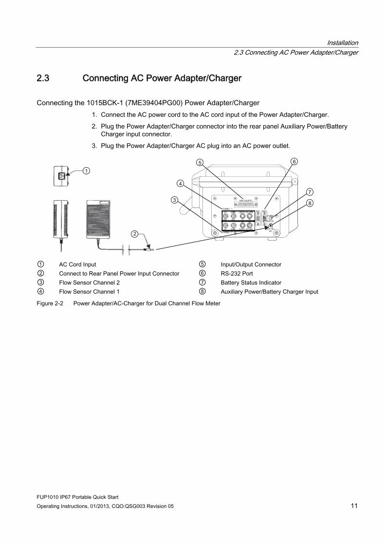
2.3 Connecting AC Power Adapter/Charger
Connecting the 1015BCK-1 (7ME39404PG00) Power Adapter/Charger 1. Connect the AC power cord to the AC cord input of the Power Adapter/Charger.
2. Plug the Power Adapter/Charger connector into the rear panel Auxiliary Power/Battery Charger input connector.
3. Plug the Power Adapter/Charger AC plug into an AC power outlet.
① AC Cord Input ⑤ Input/Output Connector ② Connect to Rear Panel Power Input Connector ⑥ RS-232 Port ③ Flow Sensor Channel 2 ⑦ Battery Status Indicator ④ Flow Sensor Channel 1 ⑧ Auxiliary Power/Battery Charger Input
Figure 2-2 Power Adapter/AC-Charger for Dual Channel Flow Meter

Installation 2.3 Connecting AC Power Adapter/Charger
FUP1010 IP67 Portable Quick Start 12 Operating Instructions, 01/2013, CQO:QSG003 Revision 05

3Commissioning
3.1 Connecting AC Power
Connecting the 1015BCK-1 (7ME39404PG00) Power Adapter/Charger 1. Connect the AC power cord to the AC Cord input of the Power Adapter/Charger.
2. Plug the Power adapter connector into the rear panel Power input connector.
① AC Cord Input ② Connect to Rear Panel Power Input Connector ③ Battery Status Indicator ④ Auxiliary Power/Battery Charger Input
Figure 3-1 Power Adapter/AC Charger for single and Dual Channel Flow Meters
FUP1010 IP67 Portable Quick Start Operating Instructions, 01/2013, CQO:QSG003 Revision 05 13
Commissioning 3.2 Navigating the Menu
FUP1010 IP67 Portable Quick Start 14 Operating Instructions, 01/2013, CQO:QSG003 Revision 05
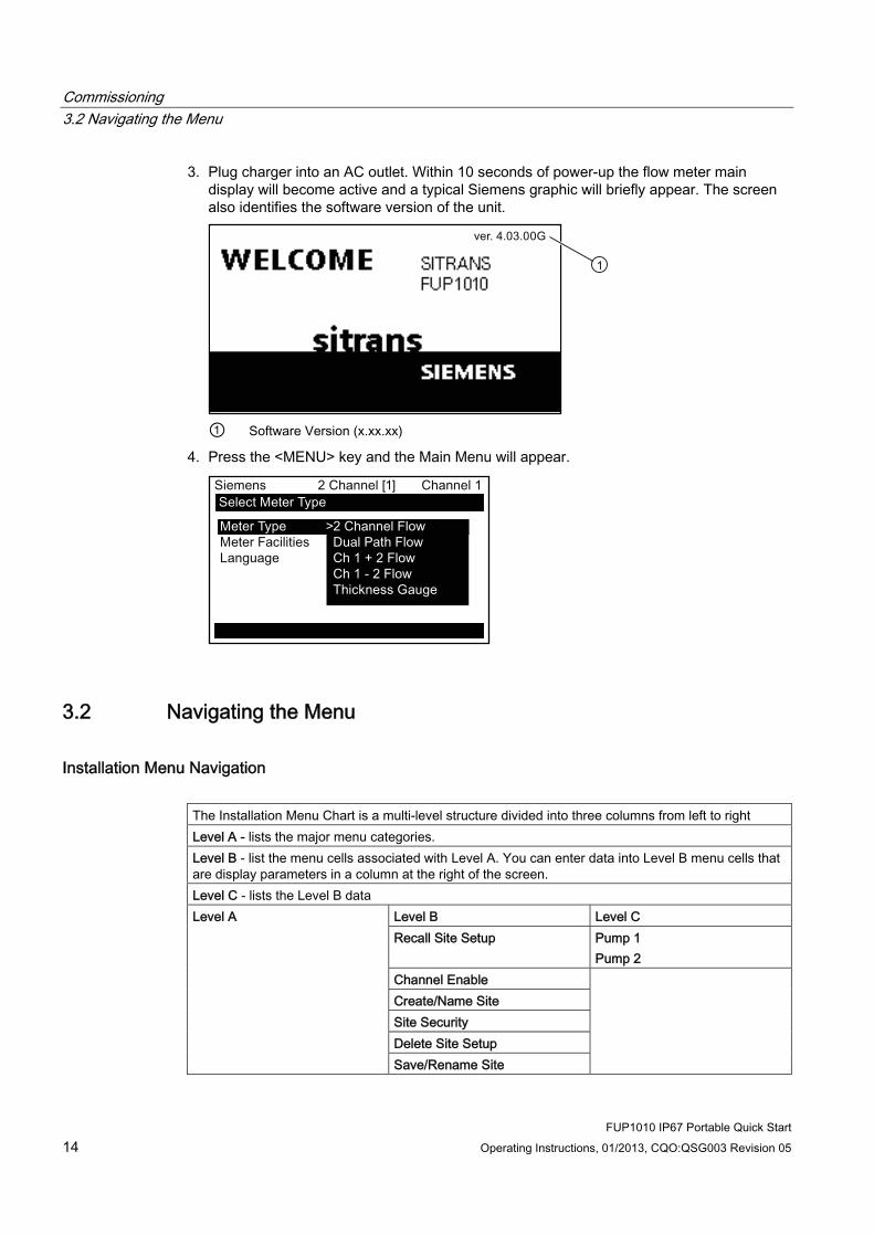
3. Plug charger into an AC outlet. Within 10 seconds of power-up the flow meter main display will become active and a typical Siemens graphic will briefly appear. The screen also identifies the software version of the unit.
① Software Version (x.xx.xx)
4. Press the <MENU> key and the Main Menu will appear.
3.2 Navigating the Menu
Installation Menu Navigation The Installation Menu Chart is a multi-level structure divided into three columns from left to right Level A - lists the major menu categories. Level B - list the menu cells associated with Level A. You can enter data into Level B menu cells that are display parameters in a column at the right of the screen. Level C - lists the Level B data
Level B Level C Recall Site Setup Pump 1
Pump 2
Level A
Channel Enable Create/Name Site Site Security Delete Site Setup Save/Rename Site
Commissioning 3.2 Navigating the Menu
FUP1010 IP67 Portable Quick Start Operating Instructions, 01/2013, CQO:QSG003 Revision 05 15
+-= +
*
F1 F3F2 F4
MENU CLR ENTER
DATALOG
ALTCTRL
HELP
1 2 30
7 8 94 5 6
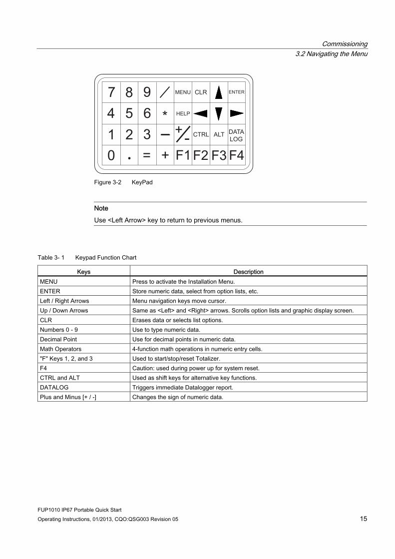
Figure 3-2 KeyPad
Note
Use <Left Arrow> key to return to previous menus.
Table 3- 1 Keypad Function Chart
Keys Description MENU Press to activate the Installation Menu. ENTER Store numeric data, select from option lists, etc. Left / Right Arrows Menu navigation keys move cursor. Up / Down Arrows Same as <Left> and <Right> arrows. Scrolls option lists and graphic display screen. CLR Erases data or selects list options. Numbers 0 - 9 Use to type numeric data. Decimal Point Use for decimal points in numeric data. Math Operators 4-function math operations in numeric entry cells. "F" Keys 1, 2, and 3 Used to start/stop/reset Totalizer. F4 Caution: used during power up for system reset. CTRL and ALT Used as shift keys for alternative key functions. DATALOG Triggers immediate Datalogger report. Plus and Minus [+ / -] Changes the sign of numeric data.
Commissioning 3.2 Navigating the Menu
FUP1010 IP67 Portable Quick Start 16 Operating Instructions, 01/2013, CQO:QSG003 Revision 05
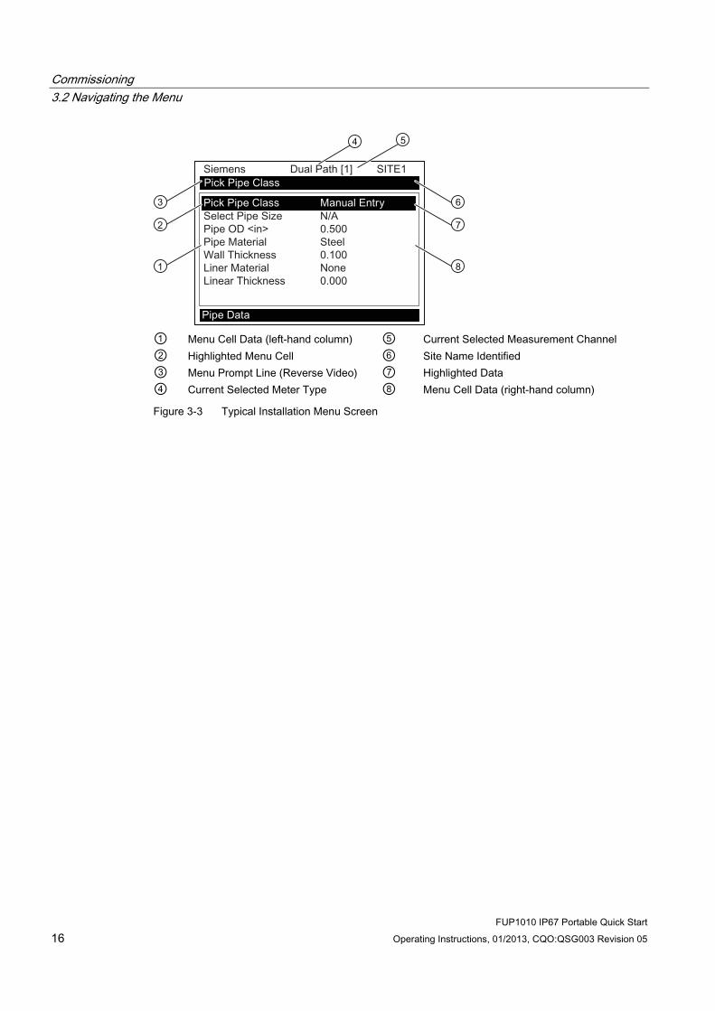
① Menu Cell Data (left-hand column) ⑤ Current Selected Measurement Channel ② Highlighted Menu Cell ⑥ Site Name Identified ③ Menu Prompt Line (Reverse Video) ⑦ Highlighted Data ④ Current Selected Meter Type ⑧ Menu Cell Data (right-hand column)
Figure 3-3 Typical Installation Menu Screen

Commissioning 3.3 Setting the Parameters
FUP1010 IP67 Portable Quick Start Operating Instructions, 01/2013, CQO:QSG003 Revision 05 17
3.3 Setting the Parameters
Select Language and Units
Note
Before creating a site select a language and then English or Metric units from the Meter Facilities menu.
Select a Meter Type 1. Press the <MENU> key and select the Meter Type.
2. Press the Right Arrow> and scroll to [2 Channel Flow]
Note
Select [2 Channel Flow] if measuring two different pipes and [2 Path Flow] if sensors are mounted on the same pipe.
3. Press <ENTER> to select. Press <Right Arrow> to select meter function. Press <ENTER>.
① Select for measuring two different pipes. (Not available for all models.) ② Select if two sensors are mounted on the same pipe. ③ Select for summing or subtracting flow from two different pipes.
Create a Site 1. Before proceeding make sure that English or Metric units have been selected.
2. At the [Channel Setup] Menu press <Right Arrow> and enter a Site name.
3. Press <ENTER> to create Site name (e.g., ABC). (See figure below.)

Commissioning 3.3 Setting the Parameters
FUP1010 IP67 Portable Quick Start 18 Operating Instructions, 01/2013, CQO:QSG003 Revision 05
Note
To set English or Metric units: In the Meter Type menu, scroll to Meter Facilities Menu. Press <Right Arrow> and select desired units. Press <ENTER> to select. Press <Left Arrow> and <Up Arrow> to return to Meter Type menu.
Note
To select letters: Press <Right Arrow> to cursor and then press <Up/Down Arrow> to select letters and numbers. Press <ENTER> when done.
① Insert desired name (8 characters max.)
4. Scroll to [Save/Rename Site]. Press <Right Arrow> then press <ENTER> to save site.
5. Press the <Left Arrow> and return to the main menu.
Select Pipe Class 1. Press the <Right Arrow> to select Pipe Class. Press <Right Arrow> again and scroll to
desired Pipe Class.
2. Press <ENTER> to select.
3. Pre-programmed Pipe Size and relevant pipe parameters will appear in menu cells. Press
<Right Arrow> and scroll to desired pipe size.

Commissioning 3.3 Setting the Parameters
FUP1010 IP67 Portable Quick Start Operating Instructions, 01/2013, CQO:QSG003 Revision 05 19
4. Press <ENTER>. Enter dimensions manually if pre-programmed dimensions do not match application.
Note
The DN sizes listed in the [Select Pipe Size] menu option list are referenced to DIN Table 2448. After selecting pipe size, check pipe OD and wall thickness for correct dimensions.
5. Press the <Left Arrow> and return to the main menu.
Select Liquid Class 1. Press the <Down Arrow> and scroll to [Application Data].
2. Press the <Right Arrow> to select [Liquid Class].
3. Press the <Right Arrow> again and scroll to desired liquid.
4. Press <ENTER> to save selection.
① Select from list.
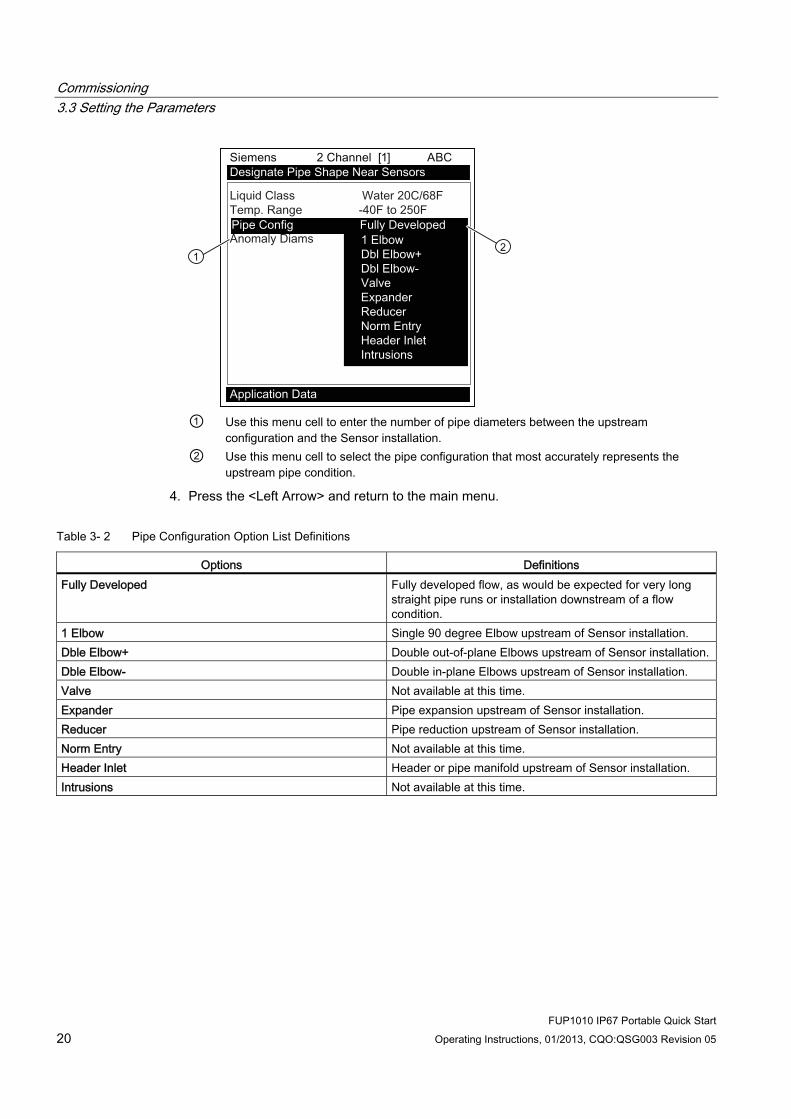
Select Pipe Configuration 1. Scroll down to [Pipe Config] and press the <Right Arrow>.
2. Select a configuration that approximates the conditions upstream of your Sensor mounting location. (Refer to the definitions below.)
3. Press <ENTER> to save selection.
Commissioning 3.3 Setting the Parameters
FUP1010 IP67 Portable Quick Start 20 Operating Instructions, 01/2013, CQO:QSG003 Revision 05
① Use this menu cell to enter the number of pipe diameters between the upstream
configuration and the Sensor installation. ② Use this menu cell to select the pipe configuration that most accurately represents the
upstream pipe condition.
4. Press the <Left Arrow> and return to the main menu.
Table 3- 2 Pipe Configuration Option List Definitions
Options Definitions Fully Developed Fully developed flow, as would be expected for very long
straight pipe runs or installation downstream of a flow condition.
1 Elbow Single 90 degree Elbow upstream of Sensor installation. Dble Elbow+ Double out-of-plane Elbows upstream of Sensor installation. Dble Elbow- Double in-plane Elbows upstream of Sensor installation. Valve Not available at this time. Expander Pipe expansion upstream of Sensor installation. Reducer Pipe reduction upstream of Sensor installation. Norm Entry Not available at this time. Header Inlet Header or pipe manifold upstream of Sensor installation. Intrusions Not available at this time.

Commissioning 3.3 Setting the Parameters
FUP1010 IP67 Portable Quick Start Operating Instructions, 01/2013, CQO:QSG003 Revision 05 21
Sensor Identification The Sensor part number located on the front face provides a detailed identification. For example, the Part Number: 1011PPS-D1 means:
1011PPS - D1
① Model ② Size
Note
Check to make sure that the Sensors are a matched set with the same serial numbers and marked with an "A" and "B" (e.g., 19256A and 19256B).
Note
Sensor Model names for Version 3 op systems are as follows: 1011H Hi Precision, 1011 Universal and 991 Universal.
Commissioning 3.3 Setting the Parameters
FUP1010 IP67 Portable Quick Start 22 Operating Instructions, 01/2013, CQO:QSG003 Revision 05
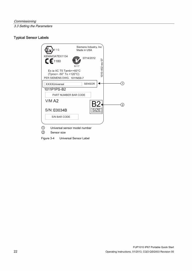
Typical Sensor Labels
① Universal sensor model number ② Sensor size
Figure 3-4 Universal Sensor Label
Commissioning 3.3 Setting the Parameters
FUP1010 IP67 Portable Quick Start Operating Instructions, 01/2013, CQO:QSG003 Revision 05 23
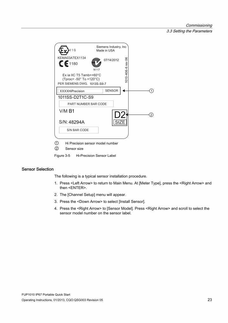
① Hi Precision sensor model number ② Sensor size
Figure 3-5 Hi-Precision Sensor Label
Sensor Selection The following is a typical sensor installation procedure.
1. Press <Left Arrow> to return to Main Menu. At [Meter Type], press the <Right Arrow> and then <ENTER>.
2. The [Channel Setup] menu will appear.
3. Press the <Down Arrow> to select [Install Sensor].
4. Press the <Right Arrow> to [Sensor Model]. Press <Right Arrow> and scroll to select the sensor model number on the sensor label.

Commissioning 3.3 Setting the Parameters
FUP1010 IP67 Portable Quick Start 24 Operating Instructions, 01/2013, CQO:QSG003 Revision 05
5. The drop down menu lists the following sensor selections:
– 1011 Universal
– 1011HP-T1 - Usable -40 to 120°C, recommended for Ø Temperature <40°C; Standard.
– 1011HP-T2 - Usable -40 to 120°C, recommended for Ø Temperature >40°C - <80°C; Named as high temperature.
– 1011HP-T3 - Usable -40 to 120°C, recommended for Ø Temperature >80°C <120°C; special request.
– 991 Universal
Note
The meter will automatically recommend a sensor depending on the application data that has been entered.
6. For this example, select the sensor model that appears on the sensor label then press <ENTER>.
① Select based on type. ② Select based on size. ③ After Sensor is mounted select [Install].
7. To select Sensor Size, press <Right Arrow>. Scroll to select the sensor size that matches the size indicated on the sensor label. Press <ENTER>.
8. At [Sensor Mount Mode], press the <Right Arrow>. Scroll to select [Reflect] or [Direct] mount and then press <ENTER>.
9. IMPORTANT: Record Spacing Method and Number Index. This data will be used to mount the sensors.
10. Sensors can now be mounted. Refer to Sensor Installation (Page 25) mounting procedures and select the mounting mode desired.
11. After sensors are mounted scroll to [Install Complete] and select [Install].

Commissioning 3.4 Sensor Installation
FUP1010 IP67 Portable Quick Start Operating Instructions, 01/2013, CQO:QSG003 Revision 05 25
3.4 Sensor Installation
3.4.1 General information
Reflect and Direct Mounting Modes Reflect and Direct mounting modes are supported for clamp-on sensors. The transmitter recommends a mounting mode after analyzing your pipe and liquid data entries. This Quick Start illustrates a typical sensor setup using the Reflect Mode.
Note
For Direct Mount refer to the Operating Instructions manual.
Mounting Supplies The following items will be needed to mount the sensors (most are supplied):
● Flat blade screwdriver
● Mounting Frames or Mounting tracks
● Tape, chalk and a ruler or measuring tape
● Mounting Straps
● Spacer Bar
● Mounting Guide (for Direct Mount)
● Ultrasonic coupling compound
● Sensors (matched set)
3.4.2 Installing the Sensors.
Reflect Mount using Mounting Frames and Spacer Bar 1. After receiving the spacing index from the Installation Menu, prepare the pipe surface
area where the sensors will be mounted.
2. Degrease the surface and remove any grit, corrosion, rust, loose paint, etc.
Before beginning refer to the Reflect Mount Installation diagram example below.
Commissioning 3.4 Sensor Installation
FUP1010 IP67 Portable Quick Start 26 Operating Instructions, 01/2013, CQO:QSG003 Revision 05
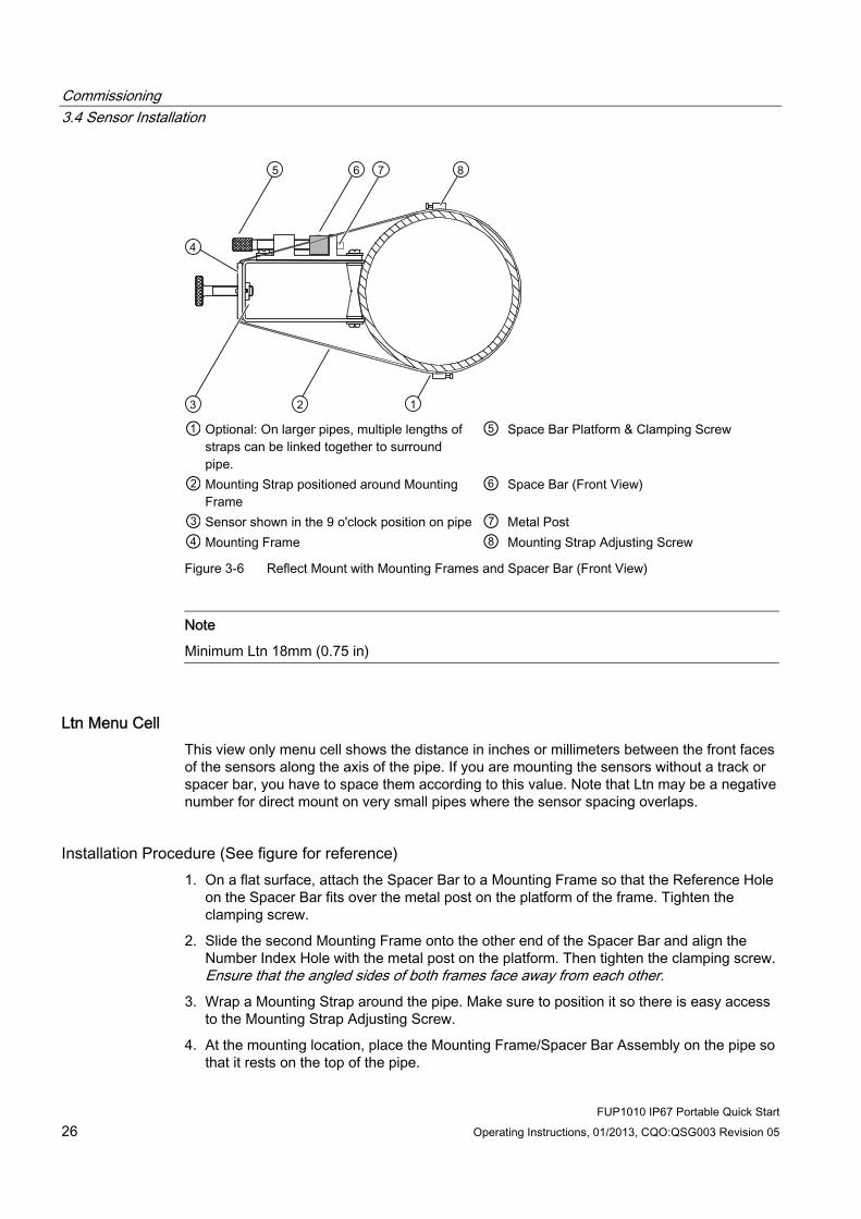
① Optional: On larger pipes, multiple lengths of
straps can be linked together to surround pipe.
⑤ Space Bar Platform & Clamping Screw
② Mounting Strap positioned around Mounting Frame
⑥ Space Bar (Front View)
③ Sensor shown in the 9 o'clock position on pipe ⑦ Metal Post ④ Mounting Frame ⑧ Mounting Strap Adjusting Screw
Figure 3-6 Reflect Mount with Mounting Frames and Spacer Bar (Front View)
Note
Minimum Ltn 18mm (0.75 in)
Ltn Menu Cell This view only menu cell shows the distance in inches or millimeters between the front faces of the sensors along the axis of the pipe. If you are mounting the sensors without a track or spacer bar, you have to space them according to this value. Note that Ltn may be a negative number for direct mount on very small pipes where the sensor spacing overlaps.
Installation Procedure (See figure for reference) 1. On a flat surface, attach the Spacer Bar to a Mounting Frame so that the Reference Hole
on the Spacer Bar fits over the metal post on the platform of the frame. Tighten the clamping screw.
2. Slide the second Mounting Frame onto the other end of the Spacer Bar and align the Number Index Hole with the metal post on the platform. Then tighten the clamping screw. Ensure that the angled sides of both frames face away from each other.
3. Wrap a Mounting Strap around the pipe. Make sure to position it so there is easy access to the Mounting Strap Adjusting Screw.
4. At the mounting location, place the Mounting Frame/Spacer Bar Assembly on the pipe so that it rests on the top of the pipe.

Commissioning 3.4 Sensor Installation
FUP1010 IP67 Portable Quick Start Operating Instructions, 01/2013, CQO:QSG003 Revision 05 27
5. Engage the end of the Mounting Strap with the Mounting Strap Adjusting Screw.
6. Slide strap under the spring clip of one of the Mounting Frames.
7. Tighten the Mounting Strap Screw enough to take up all of the slack, but not enough to prevent rotation of the assembly. Repeat procedure for the other Mounting Frame.
8. Rotate the assembly on the pipe to the final conditioned location, ensuring that it is straight along the pipe axis. (Refer to the sensor orientation diagram.)
9. Tighten the mounting straps to seat the assembly firmly on the pipe. Do not over tighten.

Commissioning 3.4 Sensor Installation
FUP1010 IP67 Portable Quick Start 28 Operating Instructions, 01/2013, CQO:QSG003 Revision 05
10. Take either sensor and apply a continuous lengthwise 3mm (1/8-inch) bead of coupling compound across the center of the sensor emitting surface.
① F-Connector ④ Front Face ② Angled Edge ⑤ Emitting Surface ③ Sensor ⑥ Coupling Compound Figure 3-7 Sensor
① ⑥ Front View Mounting Strap ② Spring Clip (Not present on some
models) ⑦ Note: Operational 2nd Mounting Strap
shown. Larger pipes over 76cm (30 inches) may need an additional support.
③ Sensor Clamping Screw ⑧ Spacer Bar Platform and Clamping Screw ④ Spacer Bar ⑨ Spacer Bar Reference Hole ⑤ 1012 Series Mounting Frame ⑩ Orientation for Single Beam Sensor at 9
o'clock position ⑪ Orientation for Dual Beam Sensor at 10 & 2
o'clock positions Figure 3-8 Sensor Installation

Commissioning 3.4 Sensor Installation
FUP1010 IP67 Portable Quick Start Operating Instructions, 01/2013, CQO:QSG003 Revision 05 29
11. Slide sensor into a mounting frame back end first aligning the angled edge of the sensor with the angled edge of the mounting frame. Keep sensor from making contact with the pipe until it butts up against the mounting frame stop. Push sensor down to mate with pipe.
12. Tighten the sensor clamping screws to hold the sensor firmly in place. Repeat procedure for the other sensor
13. Observing the upstream and downstream orientation, attach the UP and DN cables to the sensors and make snug. Attach the other ends to the UP and DN terminals of the (see figure below).
① Flow Sensor Cable Connectors ③ Channel 1 - Upstream Sensor ② To Channel 2 Flow Sensor Set ④ Channel 1 - Downstream Sensor Figure 3-9 Connecting Sensors to Flow Meter
3.4.3 Final Setup 1. At [Install Sensor] menu, scroll down to [Install Complete]. Press the <Right Arrow> and
select [Install]. Press <ENTER>. Flow meter will go through drives.
2. Observe the Measured Vs window and verify a correct sound velocity measurement (if known).
3. Press the <Down Arrow> to accept sound velocity value.
4. The meter is now ready to report flow. Press the <MENU> key twice to display flow.

Commissioning 3.4 Sensor Installation
FUP1010 IP67 Portable Quick Start 30 Operating Instructions, 01/2013, CQO:QSG003 Revision 05
Figure 3-10 Final Setup
Figure 3-11 Measuring Flow
See also Refer to I/O Connection tables (Page 35) for input/output wiring and flow meter manual for data spanning procedures.

4Troubleshooting
4.1 Troubleshooting The following is list of troubleshooting tips and messages that you may encounter. They include explanations and, in some cases, a recommended action. If a problem seems unsolvable, contact your local Siemens office or regional Ultrasonic Flow Representative for expert help at: http://www.automation.siemens.com/partner (http://www.automation.siemens.com/partner).
Table 4- 1 Troubleshooting Tips
Error or Message Probable Cause Solution Memory Full! Response to an attempt to save site data,
when data memory is full. Delete an obsolete site or clear Datalogger memory to make room for the new data.
Memory Corrupted! Memory read error occurred while accessing the active site data.
Refer to F4 reset procedure in the Operation Instructions manual.
Chan Not Setup Response to an attempt to invoke an operation that requires a channel to be enabled.
Enable the channel [Channel Setup - Channel Enable - Yes]. Note that a channel cannot be enabled until an "Install" operation is completed.
Clr Active Memory? Response to pressing and holding the F4 key during power-up.
Use the F4 key function to restore operation if a severe event (e.g., a violent power surge) disrupts system operation.
Clr Saved Data? [Clr Saved Data?] only appears after pressing the <Down Arrow> in response to [Clr Active Memory?].
Answering Yes to [Clr Saved Data?] will erase ALL saved data. To invoke in RS-232 serial mode, type @@@ and then press <ENTER> key.
<EOT> Response to a request to output Datalogger data to the printer or the Graphics screen when no Datalogger data exists or at the end of a transmitted file..
Set up the Datalogger.
No Sites - Press <ENTER>
Response while trying to recall/delete a site setup when no sites are stored.
Create a site.
Security Response upon changing previously entered data when security switch is in [Disable] position or security code has been entered.
Change switch position to [Enable]. Enter previously set security code.
RTC Error Component level problem. Meter requires service. Request RMA.
- - -F- - - Fault Alarm Loss of signal strength (ALC) Change of Rx signal location (Beam
Blowing)
Recouple sensors with fresh couplant. Install sensors in Direct mount mode Note: If problem persists call Tech support.
FUP1010 IP67 Portable Quick Start Operating Instructions, 01/2013, CQO:QSG003 Revision 05 31
Troubleshooting 4.1 Troubleshooting
FUP1010 IP67 Portable Quick Start 32 Operating Instructions, 01/2013, CQO:QSG003 Revision 05
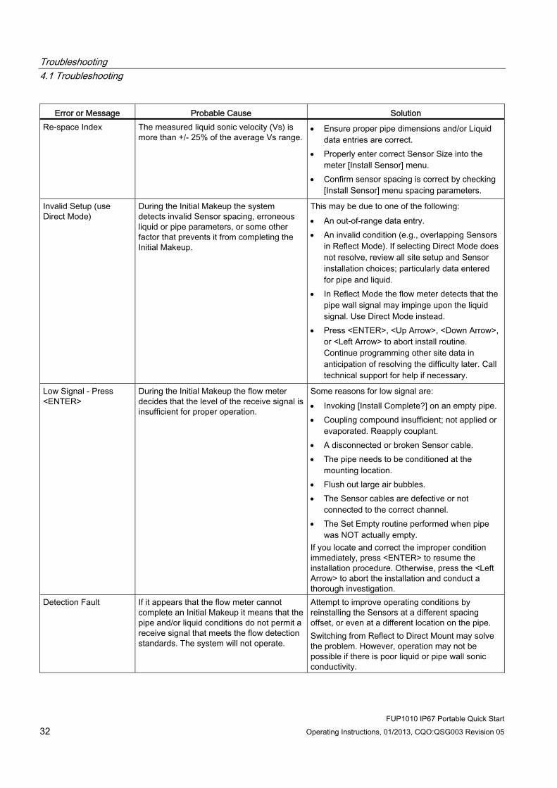
Error or Message Probable Cause Solution Re-space Index The measured liquid sonic velocity (Vs) is
more than +/- 25% of the average Vs range. Ensure proper pipe dimensions and/or Liquid
data entries are correct. Properly enter correct Sensor Size into the
meter [Install Sensor] menu. Confirm sensor spacing is correct by checking
[Install Sensor] menu spacing parameters.
Invalid Setup (use Direct Mode)
During the Initial Makeup the system detects invalid Sensor spacing, erroneous liquid or pipe parameters, or some other factor that prevents it from completing the Initial Makeup.
This may be due to one of the following: An out-of-range data entry. An invalid condition (e.g., overlapping Sensors
in Reflect Mode). If selecting Direct Mode does not resolve, review all site setup and Sensor installation choices; particularly data entered for pipe and liquid.
In Reflect Mode the flow meter detects that the pipe wall signal may impinge upon the liquid signal. Use Direct Mode instead.
Press <ENTER>, <Up Arrow>, <Down Arrow>, or <Left Arrow> to abort install routine. Continue programming other site data in anticipation of resolving the difficulty later. Call technical support for help if necessary.
Low Signal - Press <ENTER>
During the Initial Makeup the flow meter decides that the level of the receive signal is insufficient for proper operation.
Some reasons for low signal are: Invoking [Install Complete?] on an empty pipe. Coupling compound insufficient; not applied or
evaporated. Reapply couplant. A disconnected or broken Sensor cable. The pipe needs to be conditioned at the
mounting location. Flush out large air bubbles. The Sensor cables are defective or not
connected to the correct channel. The Set Empty routine performed when pipe
was NOT actually empty. If you locate and correct the improper condition immediately, press <ENTER> to resume the installation procedure. Otherwise, press the <Left Arrow> to abort the installation and conduct a thorough investigation.
Detection Fault If it appears that the flow meter cannot complete an Initial Makeup it means that the pipe and/or liquid conditions do not permit a receive signal that meets the flow detection standards. The system will not operate.
Attempt to improve operating conditions by reinstalling the Sensors at a different spacing offset, or even at a different location on the pipe. Switching from Reflect to Direct Mount may solve the problem. However, operation may not be possible if there is poor liquid or pipe wall sonic conductivity.
Troubleshooting 4.2 Alarm Codes
FUP1010 IP67 Portable Quick Start Operating Instructions, 01/2013, CQO:QSG003 Revision 05 33
Note
If you receive a Detection Fault message, it is strongly recommended that the Technical Service Department (http://www.automation.siemens.com/partner) be contacted.
4.2 Alarm Codes
Alarm Codes and Descriptions The following alarm codes appear on the main display of the flow meter.
Letter Codes Alarm Code Description
SPACE Spacing Sensor spacing may need adjustment EMPTY Empty Pipe is empty HI/LO Rate Flow above High setting or below Low setting FAULT Fault Three continuous seconds without new data update AER Aeration Current aeration percentage exceeds the alarm set point MEMRY Memory Last valid reading for a selected interval during Fault condition MAKUP Makeup In-Process Makeup occurred
The following alarm codes appear in the Datalogger status messages: I Interface Liquid Vs exceeds interface alarm set point P Pig Pig passage detected (optional) Z ZeroMatic ZeroMatic signal occurred
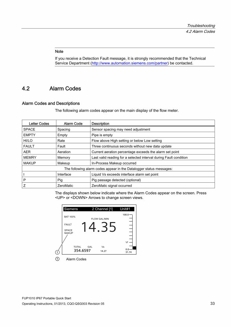
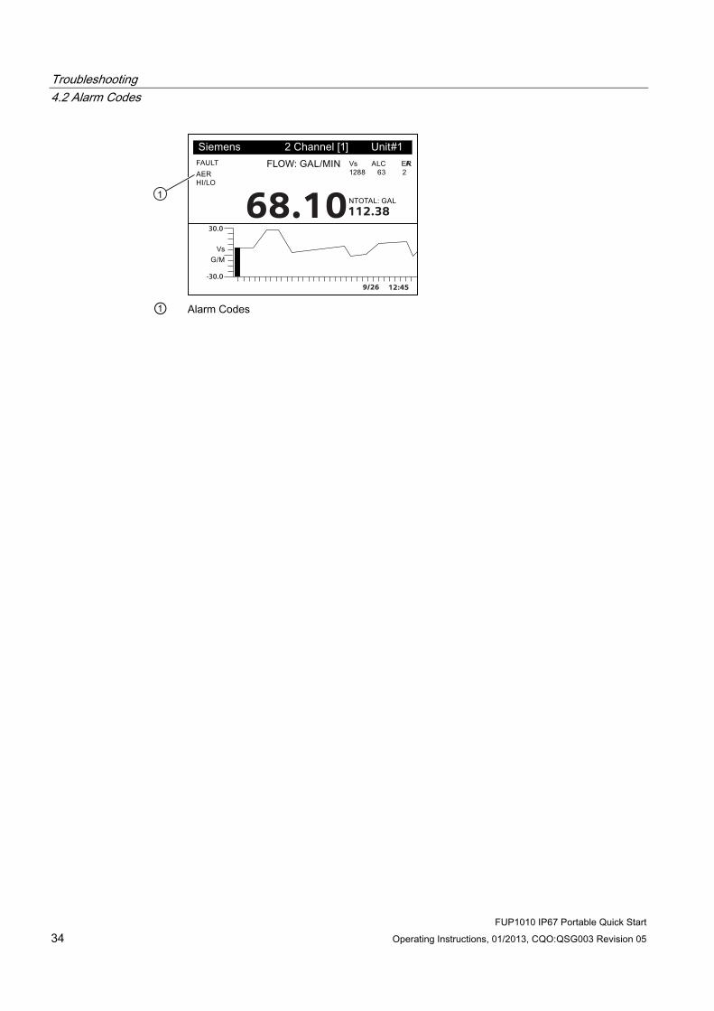
The displays shown below indicate where the Alarm Codes appear on the screen. Press <UP> or <DOWN> Arrows to change screen views.
14.35
354.6597 14.27
100.0
0.031.74
① Alarm Codes
Troubleshooting 4.2 Alarm Codes
FUP1010 IP67 Portable Quick Start 34 Operating Instructions, 01/2013, CQO:QSG003 Revision 05
9/26 12:45
68.10112.3830.0
-30.0
① Alarm Codes

Appendix AA.1 I/O Connections and Wiring
Terminal Block Wiring - FUP1010 IP67 Battery Powered 2 Channel/2 Path Weatherproof Flow Meter Wiring
(Refer to manual drawing 1010WDP-7 sheet 2 of 2)
Note
Single Channel flow meters have the same terminal pin numbers and signals.
The terminal block wiring table applies to the part numbers listed below.
Table A- 1 Part Numbers and Connection Data
1010WDP-7 (Sheet 2 of 2) Drawing FUP1010 7ME3510
FUP1010 IP67 Portable Quick Start Operating Instructions, 01/2013, CQO:QSG003 Revision 05 35
Appendix A.1 I/O Connections and Wiring
FUP1010 IP67 Portable Quick Start 36 Operating Instructions, 01/2013, CQO:QSG003 Revision 05
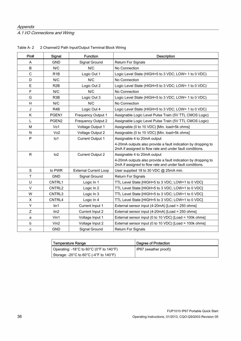
Table A- 2 2 Channel/2 Path Input/Output Terminal Block Wiring
Pin# Signal Function Description A GND Signal Ground Return For Signals B N/C N/C No Connection C R1B Logic Out 1 Logic Level State (HIGH=5 to 3 VDC; LOW= 1 to 0 VDC) D N/C N/C No Connection E R2B Logic Out 2 Logic Level State (HIGH=5 to 3 VDC; LOW= 1 to 0 VDC) F N/C N/C No Connection G R3B Logic Out 3 Logic Level State (HIGH=5 to 3 VDC; LOW= 1 to 0 VDC) H N/C N/C No Connection J R4B Logic Out 4 Logic Level State (HIGH=5 to 3 VDC; LOW= 1 to 0 VDC) K PGEN1 Frequency Output 1 Assignable Logic Level Pulse Train (5V TTL CMOS Logic) L PGEN2 Frequency Output 2 Assignable Logic Level Pulse Train (5V TTL CMOS Logic) M Vo1 Voltage Output 1 Assignable (0 to 10 VDC) [Min. load=5k ohms] N Vo2 Voltage Output 2 Assignable (0 to 10 VDC) [Min. load=5k ohms] P Io1 Current Output 1 Assignable 4 to 20mA output
4-20mA outputs also provide a fault indication by dropping to 2mA if assigned to flow rate and under fault conditions.
R Io2 Current Output 2 Assignable 4 to 20mA output 4-20mA outputs also provide a fault indication by dropping to 2mA if assigned to flow rate and under fault conditions.
S Io PWR External Current Loop User supplied 18 to 30 VDC @ 25mA min. T GND Signal Ground Return For Signals U CNTRL1 Logic In 1 TTL Level State [HIGH=5 to 3 VDC; LOW=1 to 0 VDC] V CNTRL2 Logic In 2 TTL Level State [HIGH=5 to 3 VDC; LOW=1 to 0 VDC] W CNTRL3 Logic In 3 TTL Level State [HIGH=5 to 3 VDC; LOW=1 to 0 VDC] X CNTRL4 Logic In 4 TTL Level State [HIGH=5 to 3 VDC; LOW=1 to 0 VDC] Y Iin1 Current Input 1 External sensor input (4-20mA) [Load = 250 ohms] Z Iin2 Current Input 2 External sensor input (4-20mA) [Load = 250 ohms] a Vin1 Voltage Input 1 External sensor input (0 to 10 VDC) [Load = 100k ohms] b Vin2 Voltage Input 2 External sensor input (0 to 10 VDC) [Load = 100k ohms] c GND Signal Ground Return For Signals
Temperature Range Degree of Protection Operating: -18°C to 60°C (0°F to 140°F) Storage: -20°C to 60°C (-4°F to 140°F)
IP67 (weather proof))

Appendix A.1 I/O Connections and Wiring
FUP1010 IP67 Portable Quick Start Operating Instructions, 01/2013, CQO:QSG003 Revision 05 37
Performance The following specifications apply under standard conditions (i.e., measurements taken on a straight run of 15 diameters upstream and 5 diameters downstream; flow rate above 1 fps; non-aerated Newtonian liquids flowing at Reynolds numbers <2000 or >10000).
Table A- 3 Performance Specifications
Transit-Time Accuracy At least 1% to 2 % of indicated flow (better than 0.5 % possible with calibration.)
Flow Sensitivity 0.0003 m/s (0.001 fps) - even at zero flow. Zero Drift Stability Less than 0.005 m/s (0.015 fps) Repeatability (small volume) Better than 0.5 % Response Rate (Damping) SmartSlew effective from 0.2 seconds to 5
minutes. Flow Velocity Range Min. ±12 m/s (±40 ft/s), inc. zero flow Linearity 0.0001 m/s (0.003 ft/s) Flow Profile Compensation Automatic Reynolds number correction of
reported flow rate.

Appendix A.1 I/O Connections and Wiring
FUP1010 IP67 Portable Quick Start 38 Operating Instructions, 01/2013, CQO:QSG003 Revision 05

LEVEL A LEVEL B LEVEL C LEVEL D LEVEL E LEVEL F LEVEL G LEVEL H
Meter Type 2 Channel Flow Channel 1/2 Clamp-on FastStart Setup Pick Pipe Class Enter From ListDual Path Flow Reflexor Select Pipe N/ACh 1+2 Flow Install Xdcr Transducer Model Enter From ListCh 1-2 Flow Transducer Size Enter From ListThickness Gauge Xdcr Mount Mode Enter From List
Spacing Offset Enter From ListNumber Index View onlySpacing Method View onlyLtn Value <in> View OnlyInstall Complete No/InstallEmpty Pipe Set Enter From ListZero FlowAdjust Enter From List
Full Site Setup Channel Setup Recall Site Enter From ListChannel Enable No/YesCreate/Name Site Enter Site NameSite Security On/OffDelete Site Enter From ListSave/Rename Site Enter/Clear Site Name
Pipe Data Pick Pipe Class Enter From ListSelect Pipe Size Enter From ListPipe OD (in) Numeric EntryPipe Material Enter From ListWall Thickness Numeric EntryLiner Material Enter From ListLiner Thickness Numeric Entry
Application Data Liquid Class Select Liquid Enter from ListEstimated Vs M/S Numeric EntryViscosity (cS) Numeric EntryDensity S.G. Numeric Entry
Temp. Range Enter From ListPipe Config Enter From ListAnomaly Diams Numeric Entry
Install Sensor Sensor Model Enter From ListSensor Size Enter From ListSensor Mount Mode Enter From ListSpacing Offset Enter From ListNumber Index View OnlySpacing Method View OnlyLtn Value (in) View OnlyInstall Complete No/Install Select InstallEmpty Pipe Set Enter From ListZero Flow Adjust Enter From List
Operation Adjust Damping Control Time Average / SmartSlewDeadband Control Numeric EntryMemory/Fault Set Fault/MemoryMemory Delay (s) N/A
Flow/Total Units Flow Vol. Units Enter From ListFlow Time Units Enter From ListFlow Disp. Range Autorange/HighFlow Disp. Scale Enter From ListTotal Vol. Units Enter From ListTotalizer Scale Enter From ListTotal Resolution Enter From ListTotalizer Mode Enter From ListBatch/Sample Tot Numeric Entry
Span/Set/Cal Span Data Enter From ListSet Alarm Levels Enter From ListCalib. Flowrate Intrinsic
KcMultiPoint
Display Setup Select Data Enter From ListData Display Enter From ListTime Base Enter From ListStripchart Clear Yes/No
Logger Setup Logger Mode Enter From ListLogger Data Enter From ListLogger Interval Enter From ListLogger Events Enter From ListDisplay Logger Enter From List
I/O Data Control Analog Out Setup Enter From ListRelay Setup Relay 1,2Analog Inp Setup Enter From List
Diagnostic Data Flow Data Enter From ListApplication Info Enter From ListLiquid Data Enter From ListSite Setup Data Enter From ListTest Facilities Enter From ListPrint Site Setup No/YesSite Created: View Only mm.dd.yy hh.mm.ss
FUP1010 IP67 Installation Menu Chart
This Menu Chart applies to:MLFB - 7ME3510
7ME3511
Siemens Industry, Inc.Industry Automation DivisionCoC Ultrasonic FlowHauppauge, New YorkUSAWeb: www.siemens.com/flow
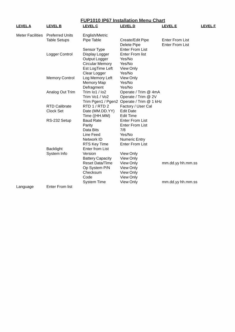
FUP1010 IP67 Installation Menu ChartLEVEL A LEVEL B LEVEL C LEVEL D LEVEL E LEVEL F
Meter Facilities Preferred Units English/MetricTable Setups Pipe Table Create/Edit Pipe Enter From List
Delete Pipe Enter From ListSensor Type Enter From List
Logger Control Display Logger Enter From listOutput Logger Yes/NoCircular Memory Yes/NoEst LogTime Left View OnlyClear Logger Yes/No
Memory Control Log Memory Left View OnlyMemory Map Yes/NoDefragment Yes/No
Analog Out Trim Trim Io1 / Io2 Operate / Trim @ 4mATrim Vo1 / Vo2 Operate / Trim @ 2VTrim Pgen1 / Pgen2 Operate / Trim @ 1 kHz
RTD Calibrate RTD 1 / RTD 2 Factory / User CalClock Set Date (MM.DD.YY) Edit Date
Time ((HH.MM) Edit TimeRS-232 Setup Baud Rate Enter From List
Parity Enter From ListData Bits 7/8Line Feed Yes/NoNetwork ID Numeric EntryRTS Key Time Enter From List
Backlight Enter from ListSystem Info Version View Only
Battery Capacity View OnlyReset Data/Time View Only mm.dd.yy hh.mm.ssOp System P/N View OnlyChecksum View OnlyCode View OnlySystem Time View Only mm.dd.yy hh.mm.ss
Language Enter From list

CL
AS
S 5
0N
om
ina
lD
iam
ete
r
3 4 6 8 10 12 14 16 18 20 24 30 36 42 48 54
N/A
N
/AN
/A
N/A
0.25
6.4
00.
27 8
.51
0.29
10.
520.
31 1
2.58
0.33
14.
640.
34 1
6.72
0.35
18.
800.
36 2
0.88
0.38
25.
040.
39 3
1.22
0.43
37.
440.
47 4
3.56
0.51
49.
780.
57 5
6.42
Wal
l I.
D.
DU
CT
ILE
IR
ON
PIP
E
Act
ual
O.D
.
3.96
4.80
6.90
9.05
11.1
013
.20
15.3
017
.40
19.5
021
.60
25.8
032
.00
38.3
044
.50
50.8
057
.56
CL
AS
S 5
1
0.25
3.
460.
26
4.28
0.28
6.
340.
30
8.45
0.32
10.
460.
34 1
2.52
0.36
14.
580.
37 1
6.66
0.38
18.
740.
39 2
0.82
0.41
24.
980.
43 3
1.14
0.48
37.
340.
53 4
3.44
0.58
49.
640.
65 5
6.26
Wal
l I.
D.
CL
AS
S 5
2
0.28
3.
400.
29
4.22
0.31
6.
280.
33
8.39
0.35
10.
400.
37 1
2.46
0.39
14.
520.
40 1
6.60
0.41
18.
680.
42 2
0.76
0.44
24.
920.
47 3
1.06
0.53
37.
240.
59 4
3.32
0.65
49.
500.
73 5
6.10
Wal
l I.
D.
CL
AS
S 5
3
0.31
3.
340.
32
4.16
0.34
6.
220.
36
8.33
0.38
10.
340.
40 1
2.40
0.42
14.
460.
43 1
6.54
0.44
18.
620.
45 2
0.70
0.47
24.
860.
51 3
0.99
0.58
37.
140.
65 4
3.20
0.72
49.
360.
81 5
5.94
Wal
l I.
D.
CL
AS
S 5
4
0.34
3.
280.
35
4.10
0.37
6.
160.
39
8.27
0.41
10.
280.
43 1
2.34
0.45
14.
400.
46 1
6.48
0.47
18.
560.
48 2
0.64
0.50
24.
800.
55 3
0.90
0.63
37.
040.
71 4
3.08
0.79
49.
220.
89 5
5.78
Wal
l I.
D.
CL
AS
S 5
5
0.37
3.
220.
38
4.04
0.40
6.
100.
42
8.21
0.44
10.
220.
46 1
2.28
0.48
14.
340.
49 1
6.42
0.50
18.
500.
51 2
0.58
0.53
24.
740.
59 3
0.82
0.68
36.
940.
77 4
2.96
0.86
49.
080.
97 5
5.62
Wal
l I.
D.
0.40
3.
160.
41
3.98
0.43
6.
040.
45
8.15
0.47
10.
160.
49 1
2.22
0.51
14.
280.
52 1
6.36
0.53
18.
440.
54 2
0.52
0.56
24.
680.
63 3
0.74
0.73
36.
840.
83 4
2.84
0.93
48.
941.
05 5
5.46
Wal
l I.
D.
CL
AS
S 5
6
0.12
50.
250
0.12
50.
250
0.12
50.
250
0.12
50.
250
0.12
50.
250
0.12
50.
250
0.18
750.
375
0.18
750.
375
0.18
750.
375
0.18
750.
375
0.18
750.
375
0.25
00.
500
0.25
00.
500
0.25
00.
500
0.25
00.
500
0.25
00.
500
Sin
gle
D
ou
ble
Lin
er (
Cem
ent)
Sie
men
s Fl
ow In
stru
men
ts15
5 P
lant
Ave
nue,
Hau
ppau
ge, N
ew Y
ork
1178
8-38
01Te
l. +1
(631
) 231
-360
0 F
ax. +
1 (6
31) 2
31-3
334
Web
: w
ww
.sie
men
s.co
m
CL
AS
S A
Pip
eS
ize
3 4 6 8 10 12 14 16 18 20 24 30 36 42 48 54 60 72 84
3.80
0.
39 3
.02
4.80
0.
42 3
.96
6.90
0.
44 6
.02
9.05
0.
46 8
.13
11.1
0 0.
50 1
0.10
13.2
0 0.
54 1
2.12
15.3
0 0.
57 1
4.16
17.4
0 0.
60 1
6.20
19.5
0 0.
64 1
8.22
21.6
0 0.
67 2
0.26
25.8
0 0.
76 2
4.28
31.7
4 0.
88 2
9.98
37.9
6 0.
99 3
5.98
44.2
0 1.
10 4
2.00
50.5
0 1.
26 4
7.98
56.6
6 1.
35 5
3.96
62.8
0 1.
39 6
0.02
75.3
4 1.
62 7
2.10
87.5
4 1.
72 8
4.10
O.D
Wal
l I.
D.
CL
AS
S B
3.96
0.
42 3
.12
5.00
0.
45 4
.10
7.10
0.
48 6
.14
9.05
0.
51 8
.03
11.1
0 0.
57 9
.96
13.2
0 0.
62 1
1.96
15.3
0 0.
66 1
3.96
17.4
0 0.
70 1
6.00
19.5
0 0.
75 1
8.00
21.6
0 0.
80 2
0.00
25.8
0 0.
89 2
4.02
32.0
0 1.
03 2
9.94
38.3
0 1.
15 3
6.00
44.5
0 1.
28 4
1.94
50.8
0 1.
42 4
7.96
57.1
0 1.
55 5
4.00
64.4
0 1.
67 6
0.06
76.0
0 1.
95 7
2.10
88.5
4 2.
22 8
4.10
O.D
Wal
l I.
D.
CL
AS
S C
3.96
0.
45 3
.06
5.00
0.
48 4
.04
7.10
0.
51 6
.08
9.30
0.
56 8
.18
11.4
0 0.
62 1
0.16
13.5
0 0.
68 1
2.14
15.6
5 0.
74 1
4.17
17.8
0 0.
80 1
6.20
19.9
2 0.
87 1
8.18
22.0
6 0.
92 2
0.22
26.3
2 1.
04 2
4.22
32.4
0 1.
20 3
0.00
38.7
0 1.
36 3
9.98
45.1
0 1.
54 4
2.02
51.4
0 1.
71 4
7.98
57.8
0 1.
90 5
4.00
64.2
0 2.
00 6
0.20
76.8
8 2.
39 7
2.10
O.D
Wal
l I.
D.
CL
AS
S D
3.96
0.
48 3
.00
5.00
0.
52 3
.96
7.10
0.
55 6
.00
9.30
0.
60 8
.10
11.4
0 0.
68 1
0.04
13.5
0 0.
75 1
2.00
15.6
5 0.
82 1
4.01
17.8
0 0.
89 1
6.02
19.9
2 0.
96 1
8.00
22.0
6 1.
03 2
0.00
26.3
2 1.
16 2
4.00
32.7
4 1.
37 3
0.00
39.1
6 1.
58 3
6.00
45.5
8 1.
78 4
2.02
51.9
8 1.
96 4
8.06
58.4
0 2.
23 5
3.94
64.8
2 2.
38 6
0.06
O.D
Wal
l I.
D.
CL
AS
S E
7.22
0.
58 6
.06
9.42
0.
66 8
.10
11.6
0 0.
74 1
0.12
13.7
8 0.
82 1
2.14
15.9
8 0.
90 1
4.18
18.1
6 0.
98 1
6.20
20.3
4 1.
07 1
8.20
22.5
4 1.
15 2
0.24
26.9
0 1.
31 2
4.28
33.1
0 1.
55 3
0.00
39.6
0 1.
80 3
6.00
O.D
Wal
l I.
D.
CL
AS
S F
7.22
0.
61 6
.00
9.42
0.
71 8
.00
11.6
0 0.
80 1
0.00
13.7
8 0.
89 1
2.00
15.9
8 0.
99 1
4.00
18.1
6 1.
08 1
6.00
20.3
4 1.
17 1
8.00
22.5
4 1.
27 2
0.00
26.9
0 1.
45 2
4.00
33.4
6 1.
73 3
0.00
40.0
4 2.
02 3
6.00
O.D
Wal
l I.
D.
CL
AS
S G
7.38
0.
65 6
.08
9.60
0.
75 8
.10
11.8
4 0.
86 1
0.12
14.0
8 0.
97 1
2.14
16.3
2 1.
07 1
4.18
18.5
4 1.
18 1
6.18
20.7
8 1.
28 1
8.22
23.0
2 1.
39 2
0.24
27.7
6 1.
75 2
4.26
O.D
Wal
l I.
D.
CL
AS
S H
7.38
0.
69 6
.00
9.60
0.
80 8
.00
11.8
4 0.
92 1
0.00
14.0
8 1.
04 1
2.00
16.3
2 1.
16 1
4.00
18.5
4 1.
27 1
6.00
20.7
8 1.
39 1
8.00
23.0
2 1.
51 2
0.00
27.7
6 1.
88 2
4.00
O.D
Wal
l I.
D.
CA
ST
IRO
N P
IPE
- A
WW
A S
TAN
DA
RD

PIP
E W
EIG
HT
FO
RM
UL
A F
OR
ST
EE
L P
IPE
(lb
s p
er f
oo
t)
10.6
8 (D
-t) t,
whe
re D
=Out
side
Dia
met
er a
nd t=
Wal
l Thi
ckne
ss
Thes
e m
ater
ials
are
gen
eral
ly a
vaila
ble
in S
ched
ules
40
and
80 o
nly.
| W
all T
hick
ness
of S
ched
ule
5S &
10S
doe
s no
t per
mit
thre
adin
g in
acco
rdan
ce w
ith th
e A
mer
ican
Sta
ndar
d fo
r Pip
e Th
read
s (A
SA
No.
B2.
1)
Wal
l thi
ckne
ss id
entic
al w
ith th
ickn
ess
of “S
tand
ard
Wei
ght”
pipe
.
^ W
all T
hick
ness
iden
tical
with
thic
knes
s of
“Ext
ra-H
eavy
” pip
e.* T
hese
do
not c
onfo
rm to
Am
eric
an S
tand
ard
B36
. 10.
24.0
0023
.563
0.21
823
.500
0.25
0
Sc
he
d.
0.84
01.
050
0.71
00.
920
0.06
50.
065
0.67
40.
884
0.08
30.
083
0.62
20.
824
0.10
90.
113
0.54
60.
742
^.1
47^
.154
1/2
3/4
STA
INL
ES
S S
TE
EL
, H
AS
TE
LL
OY
“C
” &
TIT
AN
IUM
PIP
ES
ize
O.D
.I.D
.W
all
I.D.
Wal
l
5S|
10
S|
40
S
80
S
I.D.
Wal
lI.D
.W
all
1.31
51.
660
1.18
51.
530
0.06
50.
065
1.09
71.
442
0.10
90.
109
1.04
91.
380
0.13
30.
140
0.95
71.
278
^.1
79^
.191
11
1/4
1.90
02.
375
1.77
02.
245
0.06
50.
065
1.68
22.
157
0.10
90.
109
1.61
02.
067
0.14
50.
154
1.50
01.
939
^.2
00^
.218
1 1/
22
2.87
53.
500
2.70
93.
334
0.08
30.
083
2.63
53.
260
0.12
00.
120
2.46
93.
068
0.20
30.
216
2.32
32.
900
^.2
76^
.300
2 1/
23
4.00
04.
500
3.83
44.
334
0.08
30.
083
3.76
04.
260
0.12
00.
120
3.54
84.
026
0.22
60.
237
3.36
43.
826
^.3
18^
.337
3 1/
24
5.56
36.
625
5.34
56.
407
0.10
90.
109
5.29
56.
357
0.13
40.
134
5.04
76.
065
0.25
80.
280
4.81
35.
761
^.3
75^
.432
56
8.62
510
.750
8.40
710
.482
0.10
90.
134
8.32
910
.420
0.14
80.
165
7.98
110
.020
0.32
20.
365
7.62
59.
750
^.5
00^
.500
81
0
12.7
5014
.000
12.4
3813
.688
0.15
60.
156
12.3
9013
.624
0.18
00.
188
12.0
00*
.375
11.7
50*
.500
12
14
16.0
0018
.000
15.6
7017
.670
0.16
50.
165
15.6
2417
.624
0.18
80.
188
16
18
20.0
0022
.000
19.6
3421
.624
0.18
80.
188
19.5
6421
.564
0.21
80.
218
20
22
24
7.00
1 8
.750
10.5
0011
.500
13.1
2414
.876
16.5
0018
.250
19.8
76
3.62
44.
563
5.50
17.
189
9.06
410
.750
11.8
1413
.564
15.2
5017
.000
18.7
5020
.376
7.43
9 9
.314
11.0
6412
.126
13.9
3815
.688
17.4
3819
.250
20.9
38
7.81
3 9
.750
11.6
2612
.814
14.6
8816
.500
18.3
7620
.250
22.0
64
O.D
.I.D
.W
all
Pip
e1
/2
CA
RB
ON
ST
EE
L a
nd
PV
C P
IPE
Siz
e
I.D I.D.
Wal
l
11
1/2
2 1/
24
6
Stan
d-ar
dI.D
.Ex
traSt
rong
(XS
)
^.1
47^
.154
^.1
79^
.191
^.2
00^
.218
^.2
76^
.300
^.3
18^
.337
^.3
75^
.432
^.5
000.
593
0.68
70.
750
0.84
30.
937
1.03
11.
125
1.21
8
Dou
ble
Extra
Stro
ng(X
XS)
Sche
d.10
Wal
l
Wal
l
I.D.
Wal
lSc
hed.
20I.D
.W
all
Sche
d.30
I.D.
Wal
lSc
hed.
40I.D
.W
all
Sche
d.60
I.D.
Wal
lSc
hed.
80I.D
.W
all
Sche
d.10
0I.D
.W
all
Sche
d.12
0I.D
.W
all
Sche
d.14
0I.D
.W
all
Sche
d.16
0
3/4
0.84
01.
050
1.31
51.
660
1.90
02.
375
2.87
53.
500
4.00
04.
500
5.56
36.
625
8.62
510
.750
12.7
5014
.000
16.0
0018
.000
20.0
0022
.000
24.0
0026
.000
28.0
0030
.000
32.0
0034
.000
36.0
0042
.000
0.10
90.
113
0.13
30.
140
0.14
50.
154
0.20
30.
216
0.22
60.
237
0.25
80.
280
0.32
20.
365
0.40
60.
438
^.5
000.
562
0.59
30.
687
0.25
00.
250
0.25
00.
312
0.31
20.
312
0.37
50.
375
0.37
5^
.500
^.5
00^
.500
^.5
00^
.500
^.5
00^
.500
1 1/
42
33
1/2
58
10
12
14
16
18
24
28
26
30
32
34
36
42
20
22
0.62
20.
824
1.04
91.
380
1.61
02.
067
2.46
93.
068
3.54
84.
026
5.04
76.
065
7.98
110
.020
12.0
0013
.250
15.2
5017
.250
19.2
5021
.250
23.2
5025
.250
27.2
5029
.250
31.2
5033
.250
35.2
5041
.250
0.10
90.
113
0.13
30.
140
0.14
50.
154
0.20
30.
216
0.22
60.
237
0.25
80.
280
0.32
2 0
.365
0.3
75 0
.375
0.3
75 0
.375
0.3
75 0
.375
0.3
75 0
.375
0.3
75 0
.375
0.37
50.
375
0.37
5* .
375
0.54
60.
742
0.95
71.
278
1.50
01.
939
2.32
32.
900
3.36
43.
826
4.81
35.
761
7.62
5 9
.750
11.7
5013
.000
15.0
0017
.000
19.0
0021
.000
23.0
0025
.000
27.0
0029
.000
31.0
0033
.000
35.0
0041
.000
0.14
70.
154
0.17
90.
191
0.20
00.
218
0.27
60.
300
0.31
80.
337
0.37
50.
432
0.50
0 0
.500
0.5
00 0
.500
0.5
00 0
.500
0.5
00 0
.500
0.5
00 0
.500
0.5
00 0
.500
0.50
00.
500
0.50
0* .
500
0.25
20.
434
0.59
90.
896
1.10
01.
503
1.77
12.
300
2.72
83.
152
4.06
34.
897
6.87
5 8
.750
10.7
50
0.29
40.
308
0.35
80.
382
0.40
00.
436
0.55
20.
600
0.63
60.
674
0.75
00.
864
0.87
5 1
.000
1.0
00
13.5
0015
.500
17.5
0019
.500
21.5
0023
.500
25.3
7627
.376
29.3
7631
.376
33.3
7635
.376
0.2
50 0
.250
0.2
50 0
.250
0.2
50 0
.250
0.3
12 0
.312
0.3
12 0
.312
0.3
12 0
.312
8.12
510
.250
12.2
5013
.376
15.3
7617
.376
19.2
5021
.250
23.2
5025
.000
27.0
0029
.000
31.0
0033
.000
35.0
0041
.000
8.07
110
.136
12.0
9013
.250
15.2
5017
.124
19.0
0021
.000
22.8
7626
.750
28.7
5030
.750
32.7
5034
.750
40.7
500.
277
0.30
70.
330
0.37
50.
375
0.43
8^
.500
^.5
000.
562
0.62
50.
625
0.62
50.
625
0.62
5* .
625
0.62
20.
824
1.04
91.
380
1.61
02.
067
2.46
93.
068
3.54
84.
026
5.04
76.
065
7.98
110
.020
11.9
3813
.124
15.0
0016
.876
18.1
8422
.626
0.40
6 ^
.500
0.5
62 0
.593
0.6
56 0
.750
0.8
12 0
.875
0.9
680.
546
0.74
20.
957
1.27
81.
500
1.93
92.
323
2.90
03.
364
3.82
64.
813
5.76
17.
625
9.5
6411
.376
12.5
0014
.314
16.1
2617
.938
19.7
5021
.564
0.59
3 0
.718
0.8
43 0
.937
1.0
31 1
.156
1.2
81 1
.375
1.5
31
0.43
80.
500
0.56
20.
718
0.84
3 1
.000
1.0
93 1
.218
1.3
75 1
.500
1.6
25 1
.812
0.81
2 1
.000
1.1
25 1
.250
1.4
38 1
.562
1.7
50 1
.875
2.0
620.
466
0.61
40.
815
1.16
01.
338
1.68
92.
125
2.62
43.
438
4.31
35.
189
6.81
3 8
.500
10.1
2611
.188
12.8
1414
.438
16.0
6417
.750
19.3
140.
187
0.21
80.
250
0.25
00.
281
0.34
30.
375
0.43
80.
531
0.62
50.
718
0.90
6 1
.125
1.3
12 1
.406
1.5
93 1
.781
1.9
68 2
.125
2.3
43
Siz
e1
02
02
42
4
O.D
.10
.750
20.0
0024
.000
24.0
00I.D
.10
.192
19.3
7523
.375
22.1
26W
all
0.27
90.
312
0.31
20.
937
The
abov
e si
zes
are
prod
uced
by
pipe
mills
but
dim
ensi
ons
do n
ot c
onfo
rm to
any
reg
ular
sta
n-da
rd o
r sch
edul
e.
NO
N-S
TAN
DA
RD
CA
RB
ON
Sie
men
s Fl
ow In
stru
men
ts15
5 P
lant
Ave
nue,
Hau
ppau
ge, N
ew Y
ork
1178
8-38
01Te
l. +1
(631
) 231
-360
0 F
ax. +
1 (6
31) 2
31-3
334
Web
: w
ww
.sie
men
s.co
m
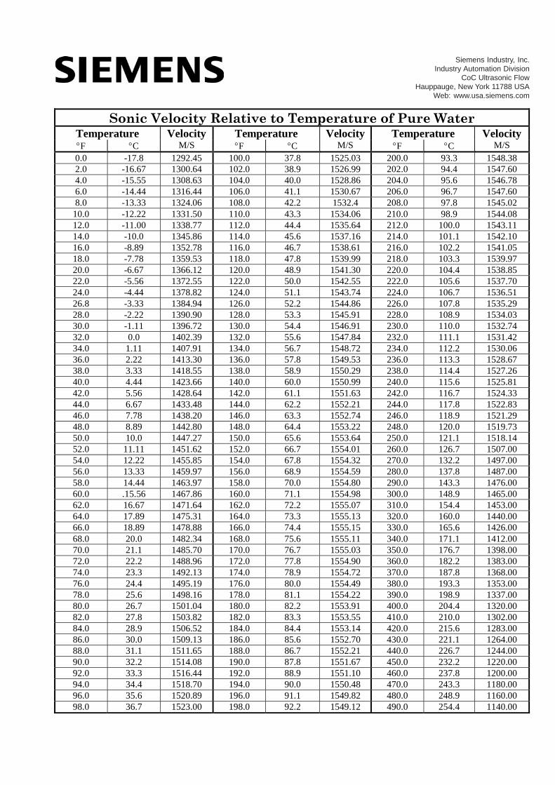
Sonic Velocity Relative to Temperature of Pure Water Temperature Velocity Temperature Velocity Temperature Velocity F C M/S F C M/S F C M/S 0.0 -17.8 1292.45 100.0 37.8 1525.03 200.0 93.3 1548.38 2.0 -16.67 1300.64 102.0 38.9 1526.99 202.0 94.4 1547.60 4.0 -15.55 1308.63 104.0 40.0 1528.86 204.0 95.6 1546.78 6.0 -14.44 1316.44 106.0 41.1 1530.67 206.0 96.7 1547.60 8.0 -13.33 1324.06 108.0 42.2 1532.4 208.0 97.8 1545.02
10.0 -12.22 1331.50 110.0 43.3 1534.06 210.0 98.9 1544.08 12.0 -11.00 1338.77 112.0 44.4 1535.64 212.0 100.0 1543.11 14.0 -10.0 1345.86 114.0 45.6 1537.16 214.0 101.1 1542.10 16.0 -8.89 1352.78 116.0 46.7 1538.61 216.0 102.2 1541.05 18.0 -7.78 1359.53 118.0 47.8 1539.99 218.0 103.3 1539.97 20.0 -6.67 1366.12 120.0 48.9 1541.30 220.0 104.4 1538.85 22.0 -5.56 1372.55 122.0 50.0 1542.55 222.0 105.6 1537.70 24.0 -4.44 1378.82 124.0 51.1 1543.74 224.0 106.7 1536.51 26.8 -3.33 1384.94 126.0 52.2 1544.86 226.0 107.8 1535.29 28.0 -2.22 1390.90 128.0 53.3 1545.91 228.0 108.9 1534.03 30.0 -1.11 1396.72 130.0 54.4 1546.91 230.0 110.0 1532.74 32.0 0.0 1402.39 132.0 55.6 1547.84 232.0 111.1 1531.42 34.0 1.11 1407.91 134.0 56.7 1548.72 234.0 112.2 1530.06 36.0 2.22 1413.30 136.0 57.8 1549.53 236.0 113.3 1528.67 38.0 3.33 1418.55 138.0 58.9 1550.29 238.0 114.4 1527.26 40.0 4.44 1423.66 140.0 60.0 1550.99 240.0 115.6 1525.81 42.0 5.56 1428.64 142.0 61.1 1551.63 242.0 116.7 1524.33 44.0 6.67 1433.48 144.0 62.2 1552.21 244.0 117.8 1522.83 46.0 7.78 1438.20 146.0 63.3 1552.74 246.0 118.9 1521.29 48.0 8.89 1442.80 148.0 64.4 1553.22 248.0 120.0 1519.73 50.0 10.0 1447.27 150.0 65.6 1553.64 250.0 121.1 1518.14 52.0 11.11 1451.62 152.0 66.7 1554.01 260.0 126.7 1507.00 54.0 12.22 1455.85 154.0 67.8 1554.32 270.0 132.2 1497.00 56.0 13.33 1459.97 156.0 68.9 1554.59 280.0 137.8 1487.00 58.0 14.44 1463.97 158.0 70.0 1554.80 290.0 143.3 1476.00 60.0 .15.56 1467.86 160.0 71.1 1554.98 300.0 148.9 1465.00 62.0 16.67 1471.64 162.0 72.2 1555.07 310.0 154.4 1453.00 64.0 17.89 1475.31 164.0 73.3 1555.13 320.0 160.0 1440.00 66.0 18.89 1478.88 166.0 74.4 1555.15 330.0 165.6 1426.00 68.0 20.0 1482.34 168.0 75.6 1555.11 340.0 171.1 1412.00 70.0 21.1 1485.70 170.0 76.7 1555.03 350.0 176.7 1398.00 72.0 22.2 1488.96 172.0 77.8 1554.90 360.0 182.2 1383.00 74.0 23.3 1492.13 174.0 78.9 1554.72 370.0 187.8 1368.00 76.0 24.4 1495.19 176.0 80.0 1554.49 380.0 193.3 1353.00 78.0 25.6 1498.16 178.0 81.1 1554.22 390.0 198.9 1337.00 80.0 26.7 1501.04 180.0 82.2 1553.91 400.0 204.4 1320.00 82.0 27.8 1503.82 182.0 83.3 1553.55 410.0 210.0 1302.00 84.0 28.9 1506.52 184.0 84.4 1553.14 420.0 215.6 1283.00 86.0 30.0 1509.13 186.0 85.6 1552.70 430.0 221.1 1264.00 88.0 31.1 1511.65 188.0 86.7 1552.21 440.0 226.7 1244.00 90.0 32.2 1514.08 190.0 87.8 1551.67 450.0 232.2 1220.00 92.0 33.3 1516.44 192.0 88.9 1551.10 460.0 237.8 1200.00 94.0 34.4 1518.70 194.0 90.0 1550.48 470.0 243.3 1180.00 96.0 35.6 1520.89 196.0 91.1 1549.82 480.0 248.9 1160.00 98.0 36.7 1523.00 198.0 92.2 1549.12 490.0 254.4 1140.00
Siemens Industry, Inc.Industry Automation Division
CoC Ultrasonic FlowHauppauge, New York 11788 USA
Web: www.usa.siemens.com

Eth
ylen
e G
lyco
l
1450
1500
1550
1600
1650
1700
1750
1800
-40
-20
020
4060
8010
0
Tem
per
atu
re (
Deg
rees
F)
Sonic Velocity (m/s)
20%
25%
30%
35%
40%
45%
50%
55%
___________________
FUP1010 IP67 (tragbar)
___________________
___________________
___________________
___________________
1Einführung
2Installation
3Inbetriebnahme
SITRANS F
4Fehlerbehebung
Ultraschall-Durchflussmessgeräte
AFUP1010 IP67 (tragbar) Quick Start Guide
Anhang
Betriebsanleitung
01/2013 CQO:QSG003 Revision 05

Siemens AG Industry Sector Postfach 48 48 90026 NÜRNBERG DEUTSCHLAND
Dokumentbestellnummer: CQO:QSG003 Ⓟ 02/2013 Änderungen vorbehalten
Copyright © Siemens AG 2013. Alle Rechte vorbehalten
Rechtliche Hinweise Warnhinweiskonzept
Dieses Handbuch enthält Hinweise, die Sie zu Ihrer persönlichen Sicherheit sowie zur Vermeidung von Sachschäden beachten müssen. Die Hinweise zu Ihrer persönlichen Sicherheit sind durch ein Warndreieck hervorgehoben, Hinweise zu alleinigen Sachschäden stehen ohne Warndreieck. Je nach Gefährdungsstufe werden die Warnhinweise in abnehmender Reihenfolge wie folgt dargestellt.
GEFAHR bedeutet, dass Tod oder schwere Körperverletzung eintreten wird, wenn die entsprechenden Vorsichtsmaßnahmen nicht getroffen werden.
WARNUNG bedeutet, dass Tod oder schwere Körperverletzung eintreten kann, wenn die entsprechenden Vorsichtsmaßnahmen nicht getroffen werden.
VORSICHT bedeutet, dass eine leichte Körperverletzung eintreten kann, wenn die entsprechenden Vorsichtsmaßnahmen nicht getroffen werden.
ACHTUNG bedeutet, dass Sachschaden eintreten kann, wenn die entsprechenden Vorsichtsmaßnahmen nicht getroffen werden.
Beim Auftreten mehrerer Gefährdungsstufen wird immer der Warnhinweis zur jeweils höchsten Stufe verwendet. Wenn in einem Warnhinweis mit dem Warndreieck vor Personenschäden gewarnt wird, dann kann im selben Warnhinweis zusätzlich eine Warnung vor Sachschäden angefügt sein.
Qualifiziertes Personal Das zu dieser Dokumentation zugehörige Produkt/System darf nur von für die jeweilige Aufgabenstellung qualifiziertem Personal gehandhabt werden unter Beachtung der für die jeweilige Aufgabenstellung zugehörigen Dokumentation, insbesondere der darin enthaltenen Sicherheits- und Warnhinweise. Qualifiziertes Personal ist auf Grund seiner Ausbildung und Erfahrung befähigt, im Umgang mit diesen Produkten/Systemen Risiken zu erkennen und mögliche Gefährdungen zu vermeiden.
Bestimmungsgemäßer Gebrauch von Siemens-Produkten Beachten Sie Folgendes:
WARNUNG Siemens-Produkte dürfen nur für die im Katalog und in der zugehörigen technischen Dokumentation vorgesehenen Einsatzfälle verwendet werden. Falls Fremdprodukte und -komponenten zum Einsatz kommen, müssen diese von Siemens empfohlen bzw. zugelassen sein. Der einwandfreie und sichere Betrieb der Produkte setzt sachgemäßen Transport, sachgemäße Lagerung, Aufstellung, Montage, Installation, Inbetriebnahme, Bedienung und Instandhaltung voraus. Die zulässigen Umgebungsbedingungen müssen eingehalten werden. Hinweise in den zugehörigen Dokumentationen müssen beachtet werden.
Marken Alle mit dem Schutzrechtsvermerk ® gekennzeichneten Bezeichnungen sind eingetragene Marken der Siemens AG. Die übrigen Bezeichnungen in dieser Schrift können Marken sein, deren Benutzung durch Dritte für deren Zwecke die Rechte der Inhaber verletzen kann.
Haftungsausschluss Wir haben den Inhalt der Druckschrift auf Übereinstimmung mit der beschriebenen Hard- und Software geprüft. Dennoch können Abweichungen nicht ausgeschlossen werden, so dass wir für die vollständige Übereinstimmung keine Gewähr übernehmen. Die Angaben in dieser Druckschrift werden regelmäßig überprüft, notwendige Korrekturen sind in den nachfolgenden Auflagen enthalten.

Inhaltsverzeichnis
1 Einführung ................................................................................................................................................. 5
1.1 Einführung......................................................................................................................................5
1.2 Lieferumfang ..................................................................................................................................5
2 Installation ................................................................................................................................................. 7
2.1 Wichtige Hinweise zur Anwendung................................................................................................7
2.2 Anpassen der internen Batterie .....................................................................................................9
2.3 Anschließen des WS-Netzadapters/Batterie-Ladegeräts ............................................................11
3 Inbetriebnahme........................................................................................................................................ 13
3.1 Anschluss an Wechselstrom........................................................................................................13
3.2 Navigation im Menü .....................................................................................................................14
3.3 Einstellen der Parameter .............................................................................................................17
3.4 Messaufnehmer-Installation.........................................................................................................25 3.4.1 Allgemeine Informationen ............................................................................................................25 3.4.2 Installation der Messaufnehmer...................................................................................................25 3.4.3 Abschluss der Installation ............................................................................................................29
4 Fehlerbehebung ...................................................................................................................................... 31
4.1 Fehlerbehebung...........................................................................................................................31
4.2 Alarmcodes ..................................................................................................................................34
A Anhang .................................................................................................................................................... 37
A.1 E/A-Anschlüsse und -Verdrahtung ..............................................................................................37
Tabellen
Tabelle 2- 1 Bestellcodes Netzkabel..................................................................................................................9 Tabelle 3- 1 Tastenfunktionen - Übersicht .......................................................................................................15 Tabelle 3- 2 Definitionen für die Optionsliste zur Rohranordnung...................................................................20 Tabelle 4- 1 Tipps zur Fehlerbehebung...........................................................................................................31 Tabelle A- 1 Teilenummern und Anschlussdaten ............................................................................................37 Tabelle A- 2 E/A-Klemmleistenverdrahtung Zweikanal-/Zweipfad-Gerät.........................................................38 Tabelle A- 3 Technische Leistungsdaten .........................................................................................................39
FUP1010 IP67 (tragbar) Quick Start Guide Betriebsanleitung, 01/2013, CQO:QSG003 Revision 05 3

Inhaltsverzeichnis
FUP1010 IP67 (tragbar) Quick Start Guide 4 Betriebsanleitung, 01/2013, CQO:QSG003 Revision 05
Bilder
Bild 2-1 Netzadapter/Batterie-Ladegerät.....................................................................................................8 Bild 2-2 Netzadapter/WS-Ladegerät für Zweikanal-Durchflussmessgerät................................................11 Bild 3-1 Netzadapter/WS-Ladegerät für Ein- und Zweikanal-Durchflussmessgeräte ...............................13 Bild 3-2 Tastenfeld.....................................................................................................................................15 Bild 3-3 Typische Anzeige des Installationsmenüs ...................................................................................16 Bild 3-4 Schild eines Universal-Messaufnehmers.....................................................................................22 Bild 3-5 Schild eines Präzisions-Messaufnehmers ...................................................................................23 Bild 3-6 Reflekt-Montage mit Montagerahmen und Abstandshalter (Ansicht von vorne) .........................26 Bild 3-7 Messaufnehmer ...........................................................................................................................28 Bild 3-8 Messaufnehmer-Installation.........................................................................................................28 Bild 3-9 Anschließen der Messaufnehmer an das Durchflussmessgerät .................................................29 Bild 3-10 Abschluss der Installation ............................................................................................................30 Bild 3-11 Durchfluss messen.......................................................................................................................30

Einführung 11.1 Einführung
Einführung Der vorliegende Quick Start Guide behandelt die tragbaren Durchflussmessgeräte Siemens FUP1010 IP67 in wetterfester Ausführung. Er enthält Verfahren zum Anpassen und Aufladen der Batterien und zur Verwendung des WS-Netzadapters. Es wird eine typische Installation und Konfiguration unter Verwendung von Transducern der D-Serie im Reflekt-Modus dargestellt (Informationen zum Direkt-Modus enthält die Betriebsanleitung zum Durchflussmessgerät). Die hier dargestellten Vorgehensweisen gelten für Einkanal- und Mehrkanalgeräte gleichermaßen.
Das Siemens Si-Ware-Programm als Hilfe bei der Installation des Durchflussmessgeräts kann unter [http://s13.me/ns/cv] heruntergeladen werden.
Hinweis
Wichtiger Sicherheitshinweis: Ausführliche Sicherheitsinformationen und Angaben über zulassungsspezifische Werte sind der Betriebsanleitung zu entnehmen, die im Lieferumfang enthalten ist.
Hinweis
Der vorliegende Quick Start Guide bezieht sich auf die folgenden Betriebssysteme des FUP1010 IP67 (wetterfest): Version 3.02.02 und höher sowie Version 4.03.00 und höher.
1.2 Lieferumfang ● Messumformer SITRANS FUS1010 IP65 NEMA 4X & IP66 NEMA 7
● SITRANS F-Dokumentations-CD
● Quick Start Guide
Hinweis
Weitere Bestandteile des Lieferumfangs finden Sie auf dem Packzettel.
FUP1010 IP67 (tragbar) Quick Start Guide Betriebsanleitung, 01/2013, CQO:QSG003 Revision 05 5

Einführung 1.2 Lieferumfang
FUP1010 IP67 (tragbar) Quick Start Guide 6 Betriebsanleitung, 01/2013, CQO:QSG003 Revision 05
Installation 22.1 Wichtige Hinweise zur Anwendung
Grundvoraussetzungen ● Bestimmen Sie Rohrmaterial und Rohrmaße.
● Vermeiden Sie senkrechte Rohre mit Fließrichtung nach unten.
● Vermeiden Sie nach Möglichkeit die Montage von Messaufnehmern auf der Ober- oder Unterseite von waagerechten Rohren.
● Wählen Sie eine Montagestelle am längsten verfügbaren geraden Rohrabschnitt.
● Bestimmen Sie die Rohranordnung in Fließrichtung aufwärts (Rohrbogen, Rohrverengung usw.).
● Die Rohroberfläche sollte glatt und ggf. frei von Farbschichten sein.
● Vermeiden Sie in Fließrichtung aufwärts liegende Bauteile zur Druckminderung.
● Vermeiden Sie die Montage auf oder in der Nähe von Rohrschweißnähten.
● Das Rohr muss voll sein, damit das System richtig funktioniert.
Das Durchflussmessgerät ist wahlweise mit einem Batterie-Ladegerät erhältlich, das an eine Wechselstromquelle mit 100, 110 oder 220 V (50 Hz oder 60 Hz) angeschlossen werden kann. Es verfügt über einen universellen Eingang, der keine Umschaltung durch den Bediener erfordert. Für den Anschluss an die Wechselstromnetze der meisten Länder sind Anschlusskabel erhältlich.
VORSICHT Der Netzadapter bzw. das Batterie-Ladegerät 1015BCK-1 ist NICHT wasserdicht oder wasserabweisend.
Der Einsatz in einer nassen Umgebung oder unter Wasser führt zu Schäden am Gerät, die nicht repariert werden können und kann zu Stromschlaggefahr für den Bediener führen.
Sie sind vor Nässe zu schützen und dürfen im nassen Zustand nicht verwendet werden.
FUP1010 IP67 (tragbar) Quick Start Guide Betriebsanleitung, 01/2013, CQO:QSG003 Revision 05 7
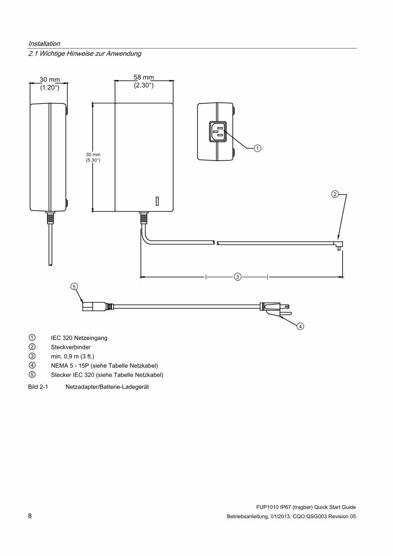
Installation 2.1 Wichtige Hinweise zur Anwendung
FUP1010 IP67 (tragbar) Quick Start Guide 8 Betriebsanleitung, 01/2013, CQO:QSG003 Revision 05
① IEC 320 Netzeingang ②. Steckverbinder ③ min. 0,9 m (3 ft.) ④ NEMA 5 - 15P (siehe Tabelle Netzkabel) ⑤ Stecker IEC 320 (siehe Tabelle Netzkabel)
Bild 2-1 Netzadapter/Batterie-Ladegerät
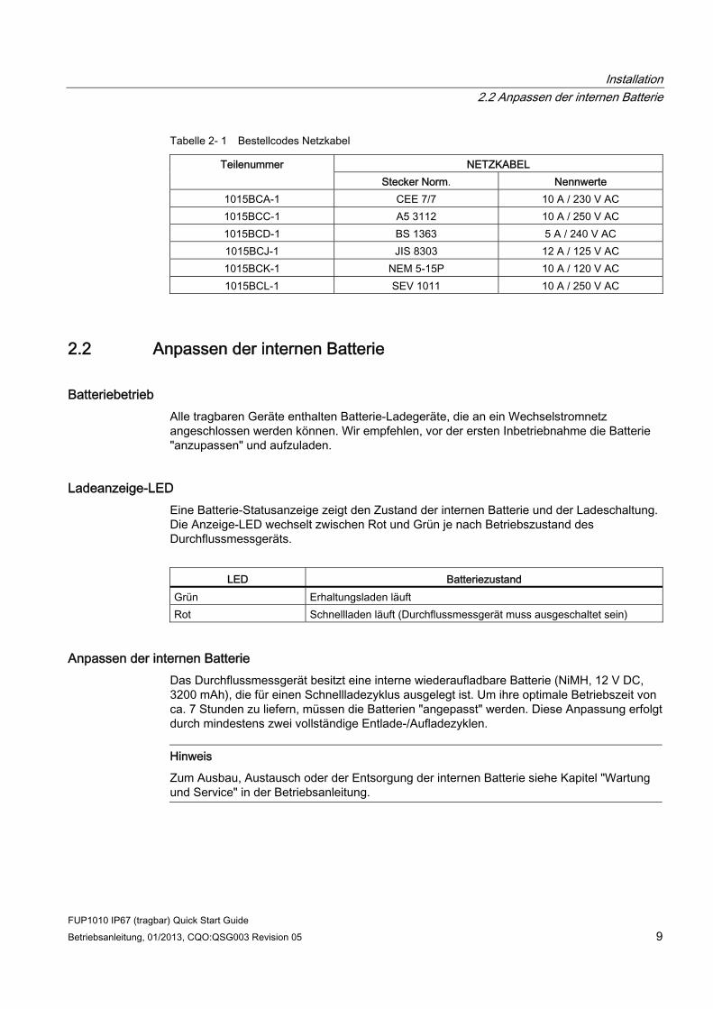
Installation 2.2 Anpassen der internen Batterie
FUP1010 IP67 (tragbar) Quick Start Guide Betriebsanleitung, 01/2013, CQO:QSG003 Revision 05 9
Tabelle 2- 1 Bestellcodes Netzkabel
NETZKABEL Teilenummer Stecker Norm. Nennwerte
1015BCA-1 CEE 7/7 10 A / 230 V AC 1015BCC-1 A5 3112 10 A / 250 V AC 1015BCD-1 BS 1363 5 A / 240 V AC 1015BCJ-1 JIS 8303 12 A / 125 V AC 1015BCK-1 NEM 5-15P 10 A / 120 V AC 1015BCL-1 SEV 1011 10 A / 250 V AC
2.2 Anpassen der internen Batterie
Batteriebetrieb Alle tragbaren Geräte enthalten Batterie-Ladegeräte, die an ein Wechselstromnetz angeschlossen werden können. Wir empfehlen, vor der ersten Inbetriebnahme die Batterie "anzupassen" und aufzuladen.
Ladeanzeige-LED Eine Batterie-Statusanzeige zeigt den Zustand der internen Batterie und der Ladeschaltung. Die Anzeige-LED wechselt zwischen Rot und Grün je nach Betriebszustand des Durchflussmessgeräts.
LED Batteriezustand
Grün Erhaltungsladen läuft Rot Schnellladen läuft (Durchflussmessgerät muss ausgeschaltet sein)
Anpassen der internen Batterie Das Durchflussmessgerät besitzt eine interne wiederaufladbare Batterie (NiMH, 12 V DC, 3200 mAh), die für einen Schnellladezyklus ausgelegt ist. Um ihre optimale Betriebszeit von ca. 7 Stunden zu liefern, müssen die Batterien "angepasst" werden. Diese Anpassung erfolgt durch mindestens zwei vollständige Entlade-/Aufladezyklen.
Hinweis
Zum Ausbau, Austausch oder der Entsorgung der internen Batterie siehe Kapitel "Wartung und Service" in der Betriebsanleitung.
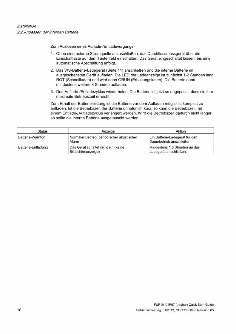
Installation 2.2 Anpassen der internen Batterie
FUP1010 IP67 (tragbar) Quick Start Guide 10 Betriebsanleitung, 01/2013, CQO:QSG003 Revision 05
Zum Auslösen eines Auflade-/Entladevorgangs:
1. Ohne eine externe Stromquelle anzuschließen, das Durchflussmessgerät über die Einschalttaste auf dem Tastenfeld einschalten. Das Gerät eingeschaltet lassen, bis eine automatische Abschaltung erfolgt.
2. Das WS-Batterie-Ladegerät (Seite 11) anschließen und die interne Batterie im ausgeschalteten Gerät aufladen. Die LED der Ladeanzeige ist zunächst 1-2 Stunden lang ROT (Schnellladen) und wird dann GRÜN (Erhaltungsladen). Die Batterie dann mindestens weitere 8 Stunden aufladen.
3. Den Auflade-/Entladezyklus wiederholen. Die Batterie ist jetzt so angepasst, dass sie ihre maximale Betriebszeit erreicht.
Zum Erhalt der Batterieleistung ist die Batterie vor dem Aufladen möglichst komplett zu entladen. Ist die Betriebszeit der Batterie unnatürlich kurz, so kann die Betriebszeit mit einem Entlade-/Aufladezyklus verlängert werden. Wird die Betriebszeit dadurch nicht länger, so sollte die interne Batterie ausgetauscht werden.
Status Anzeige Aktion
Batterie-Warnton Normaler Betrieb, periodischer akustischer Alarm
Ein Batterie-Ladegerät für den Dauerbetrieb anschließen.
Batterie-Entladung Das Gerät schaltet nicht ein (keine Bildschirmanzeige)
Mindestens 1,5 Stunden an das Ladegerät anschließen.
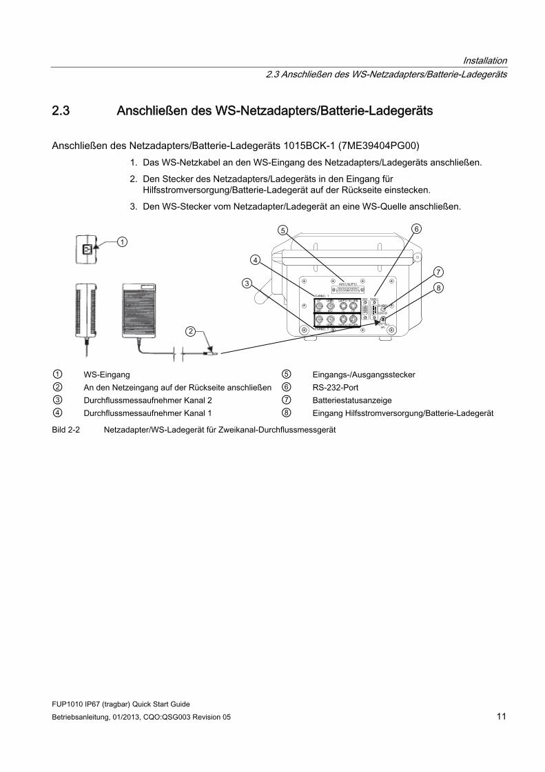
Installation 2.3 Anschließen des WS-Netzadapters/Batterie-Ladegeräts
FUP1010 IP67 (tragbar) Quick Start Guide Betriebsanleitung, 01/2013, CQO:QSG003 Revision 05 11
2.3 Anschließen des WS-Netzadapters/Batterie-Ladegeräts
Anschließen des Netzadapters/Batterie-Ladegeräts 1015BCK-1 (7ME39404PG00) 1. Das WS-Netzkabel an den WS-Eingang des Netzadapters/Ladegeräts anschließen.
2. Den Stecker des Netzadapters/Ladegeräts in den Eingang für Hilfsstromversorgung/Batterie-Ladegerät auf der Rückseite einstecken.
3. Den WS-Stecker vom Netzadapter/Ladegerät an eine WS-Quelle anschließen.
① WS-Eingang ⑤ Eingangs-/Ausgangsstecker ② An den Netzeingang auf der Rückseite anschließen ⑥ RS-232-Port ③ Durchflussmessaufnehmer Kanal 2 ⑦ Batteriestatusanzeige ④ Durchflussmessaufnehmer Kanal 1 ⑧ Eingang Hilfsstromversorgung/Batterie-Ladegerät
Bild 2-2 Netzadapter/WS-Ladegerät für Zweikanal-Durchflussmessgerät

Installation 2.3 Anschließen des WS-Netzadapters/Batterie-Ladegeräts
FUP1010 IP67 (tragbar) Quick Start Guide 12 Betriebsanleitung, 01/2013, CQO:QSG003 Revision 05

3Inbetriebnahme
3.1 Anschluss an Wechselstrom
Anschließen des Netzadapters/Batterie-Ladegeräts 1015BCK-1 (7ME39404PG00) 1. Das WS-Netzkabel an den WS-Eingang des Netzadapters/Ladegeräts anschließen.
2. Den Stecker des Netzadapters an den Netzeingang auf der Rückseite anschließen.
① WS-Eingang ② An den Netzeingang auf der Rückseite anschließen ③ Batteriestatusanzeige ④ Eingang Hilfsstromversorgung/Batterie-Ladegerät
Bild 3-1 Netzadapter/WS-Ladegerät für Ein- und Zweikanal-Durchflussmessgeräte
FUP1010 IP67 (tragbar) Quick Start Guide Betriebsanleitung, 01/2013, CQO:QSG003 Revision 05 13

Inbetriebnahme 3.2 Navigation im Menü
FUP1010 IP67 (tragbar) Quick Start Guide 14 Betriebsanleitung, 01/2013, CQO:QSG003 Revision 05
3. Das Ladegerät an eine WS-Steckdose anschließen. Innerhalb von 10 Sekunden nach dem Einschalten leuchtet die Hauptanzeige des Durchflussmessgeräts auf und zeigt ein typisches Siemens-Startbild. Auf dem Startbild erscheint auch die Software-Version des Geräts.
① Software-Version (x.xx.xx)
4. Drücken Sie Taste <MENU>, um das Hauptmenü aufzurufen.
3.2 Navigation im Menü
Navigation im Installationsmenü Das Diagramm des Installationsmenüs zeigt die Menüebenen in drei Spalten von links nach rechts (=Menüebenen von oben nach unten). Ebene A - enthält die Hauptmenükategorien. Ebene B - enthält die der Ebene A zugeordneten Menüfelder. In die Menüfelder der Ebene B können Daten eingegeben werden, die Anzeigeparameter in einer Spalte rechts auf dem Bildschirm sind. Ebene C - enthält Auswahldaten für Ebene B.
Ebene B Ebene C Messortkonfiguration abrufen Pumpe 1
Pumpe 2
Ebene A
Kanal aktivieren Anl/Name Messort Messortsicherh. Messortkonfiguration loeschen Ort sp./umbenenn
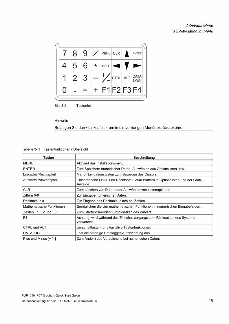
Inbetriebnahme 3.2 Navigation im Menü
FUP1010 IP67 (tragbar) Quick Start Guide Betriebsanleitung, 01/2013, CQO:QSG003 Revision 05 15
+-= +
*
F1 F3F2 F4
MENU CLR ENTER
DATALOG
ALTCTRL
HELP
1 2 30
7 8 94 5 6
Bild 3-2 Tastenfeld
Hinweis
Betätigen Sie den <Linkspfeil>, um in die vorherigen Menüs zurückzukehren.
Tabelle 3- 1 Tastenfunktionen - Übersicht
Tasten Beschreibung MENU Aktiviert das Installationsmenü. ENTER Zum Speichern numerischer Daten, Auswählen aus Optionslisten usw. Linkspfeil/Rechtspfeil Menü-Navigationstasten zum Bewegen des Cursors. Aufwärts-/Abwärtspfeil Entsprechend Links- und Rechtspfeil. Zum Blättern in Optionslisten und der Grafik-
Anzeige. CLR Zum Löschen von Daten oder Auswählen von Listenoptionen. Ziffern 0-9 Zur Eingabe numerischer Daten. Dezimalpunkt Zur Eingabe des Dezimalpunktes bei Zahlen. Mathematische Funktionen Ermöglichen die vier mathematischen Funktionen in numerischen Eingabefeldern. Tasten F1, F2 und F3 Zum Starten/Beenden/Zurücksetzen des Zählers. F4 Achtung: wird während des Einschaltvorgangs zum Rücksetzen des Systems
verwendet. CTRL und ALT Umschalttasten für alternative Tastenfunktionen. DATALOG Löst die sofortige Datalogger-Aufzeichnung aus. Plus und Minus [+ / -] Zum Ändern des Vorzeichens bei numerischen Daten.

Inbetriebnahme 3.2 Navigation im Menü
FUP1010 IP67 (tragbar) Quick Start Guide 16 Betriebsanleitung, 01/2013, CQO:QSG003 Revision 05
① Daten im Menüfeld (linke Spalte) ⑤ Aktuell ausgewählter Messkanal ② Markiertes Menüfeld ⑥ Messort Name ③ Menü-Befehlszeile (invertiert) ⑦ Markierte Daten ④ Aktuell ausgewählte Funktionsart ⑧ Daten im Menüfeld (rechte Spalte)
Bild 3-3 Typische Anzeige des Installationsmenüs
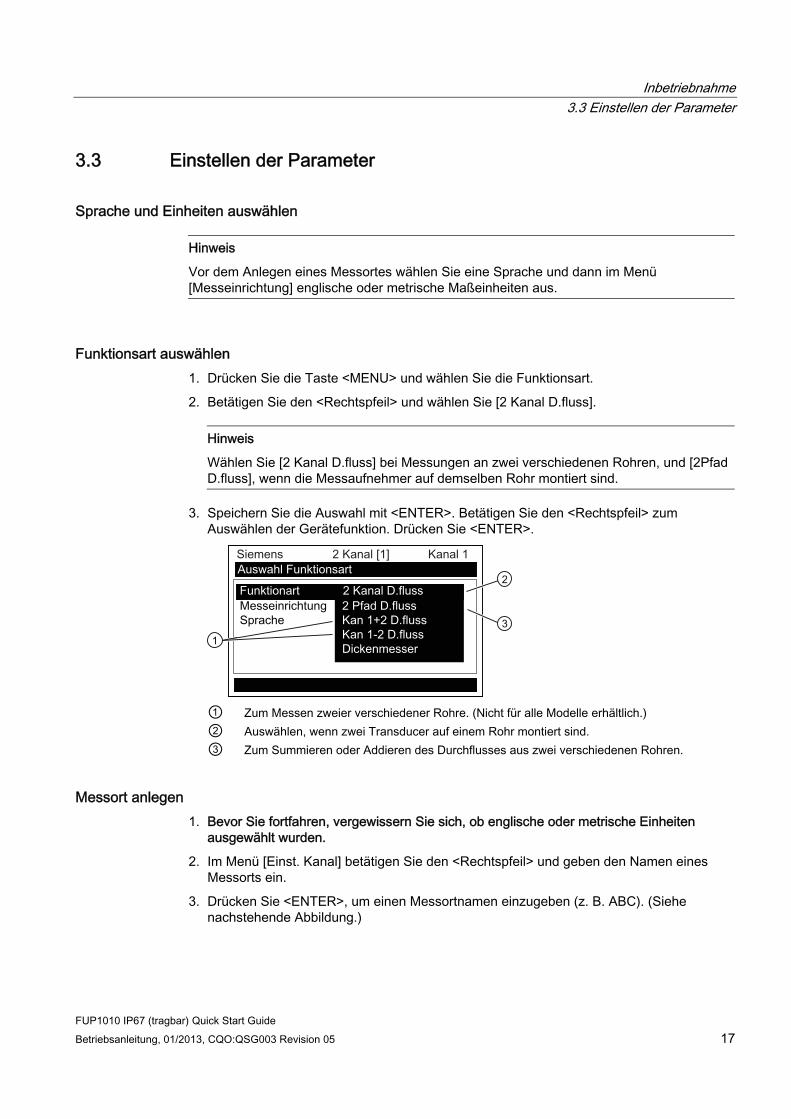
Inbetriebnahme 3.3 Einstellen der Parameter
FUP1010 IP67 (tragbar) Quick Start Guide Betriebsanleitung, 01/2013, CQO:QSG003 Revision 05 17
3.3 Einstellen der Parameter
Sprache und Einheiten auswählen
Hinweis
Vor dem Anlegen eines Messortes wählen Sie eine Sprache und dann im Menü [Messeinrichtung] englische oder metrische Maßeinheiten aus.
Funktionsart auswählen 1. Drücken Sie die Taste <MENU> und wählen Sie die Funktionsart.
2. Betätigen Sie den <Rechtspfeil> und wählen Sie [2 Kanal D.fluss].
Hinweis
Wählen Sie [2 Kanal D.fluss] bei Messungen an zwei verschiedenen Rohren, und [2Pfad D.fluss], wenn die Messaufnehmer auf demselben Rohr montiert sind.
3. Speichern Sie die Auswahl mit <ENTER>. Betätigen Sie den <Rechtspfeil> zum Auswählen der Gerätefunktion. Drücken Sie <ENTER>.
① Zum Messen zweier verschiedener Rohre. (Nicht für alle Modelle erhältlich.) ② Auswählen, wenn zwei Transducer auf einem Rohr montiert sind. ③ Zum Summieren oder Addieren des Durchflusses aus zwei verschiedenen Rohren.
Messort anlegen 1. Bevor Sie fortfahren, vergewissern Sie sich, ob englische oder metrische Einheiten
ausgewählt wurden.
2. Im Menü [Einst. Kanal] betätigen Sie den <Rechtspfeil> und geben den Namen eines Messorts ein.
3. Drücken Sie <ENTER>, um einen Messortnamen einzugeben (z. B. ABC). (Siehe nachstehende Abbildung.)
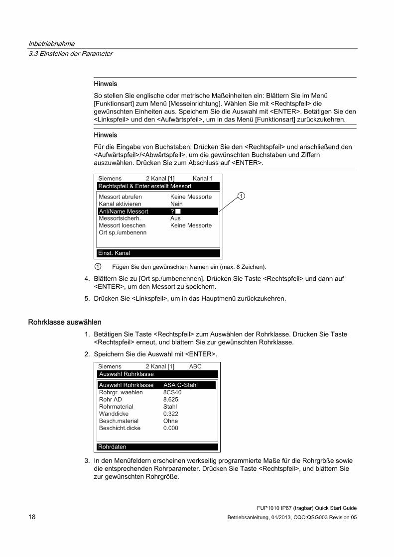
Inbetriebnahme 3.3 Einstellen der Parameter
FUP1010 IP67 (tragbar) Quick Start Guide 18 Betriebsanleitung, 01/2013, CQO:QSG003 Revision 05
Hinweis
So stellen Sie englische oder metrische Maßeinheiten ein: Blättern Sie im Menü [Funktionsart] zum Menü [Messeinrichtung]. Wählen Sie mit <Rechtspfeil> die gewünschten Einheiten aus. Speichern Sie die Auswahl mit <ENTER>. Betätigen Sie den <Linkspfeil> und den <Aufwärtspfeil>, um in das Menü [Funktionsart] zurückzukehren.
Hinweis
Für die Eingabe von Buchstaben: Drücken Sie den <Rechtspfeil> und anschließend den <Aufwärtspfeil>/<Abwärtspfeil>, um die gewünschten Buchstaben und Ziffern auszuwählen. Drücken Sie zum Abschluss auf <ENTER>.
① Fügen Sie den gewünschten Namen ein (max. 8 Zeichen).
4. Blättern Sie zu [Ort sp./umbenennen]. Drücken Sie Taste <Rechtspfeil> und dann auf <ENTER>, um den Messort zu speichern.
5. Drücken Sie <Linkspfeil>, um in das Hauptmenü zurückzukehren.
Rohrklasse auswählen 1. Betätigen Sie Taste <Rechtspfeil> zum Auswählen der Rohrklasse. Drücken Sie Taste
<Rechtspfeil> erneut, und blättern Sie zur gewünschten Rohrklasse.
2. Speichern Sie die Auswahl mit <ENTER>.
3. In den Menüfeldern erscheinen werkseitig programmierte Maße für die Rohrgröße sowie
die entsprechenden Rohrparameter. Drücken Sie Taste <Rechtspfeil>, und blättern Sie zur gewünschten Rohrgröße.
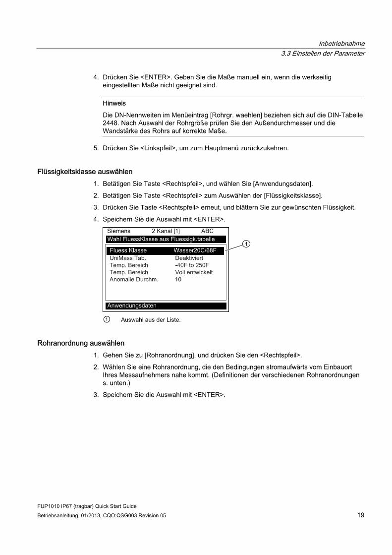
Inbetriebnahme 3.3 Einstellen der Parameter
FUP1010 IP67 (tragbar) Quick Start Guide Betriebsanleitung, 01/2013, CQO:QSG003 Revision 05 19
4. Drücken Sie <ENTER>. Geben Sie die Maße manuell ein, wenn die werkseitig eingestellten Maße nicht geeignet sind.
Hinweis
Die DN-Nennweiten im Menüeintrag [Rohrgr. waehlen] beziehen sich auf die DIN-Tabelle 2448. Nach Auswahl der Rohrgröße prüfen Sie den Außendurchmesser und die Wandstärke des Rohrs auf korrekte Maße.
5. Drücken Sie <Linkspfeil>, um zum Hauptmenü zurückzukehren.
Flüssigkeitsklasse auswählen 1. Betätigen Sie Taste <Rechtspfeil>, und wählen Sie [Anwendungsdaten].
2. Betätigen Sie Taste <Rechtspfeil> zum Auswählen der [Flüssigkeitsklasse].
3. Drücken Sie Taste <Rechtspfeil> erneut, und blättern Sie zur gewünschten Flüssigkeit.
4. Speichern Sie die Auswahl mit <ENTER>.
① Auswahl aus der Liste.
Rohranordnung auswählen 1. Gehen Sie zu [Rohranordnung], und drücken Sie den <Rechtspfeil>.
2. Wählen Sie eine Rohranordnung, die den Bedingungen stromaufwärts vom Einbauort Ihres Messaufnehmers nahe kommt. (Definitionen der verschiedenen Rohranordnungen s. unten.)
3. Speichern Sie die Auswahl mit <ENTER>.
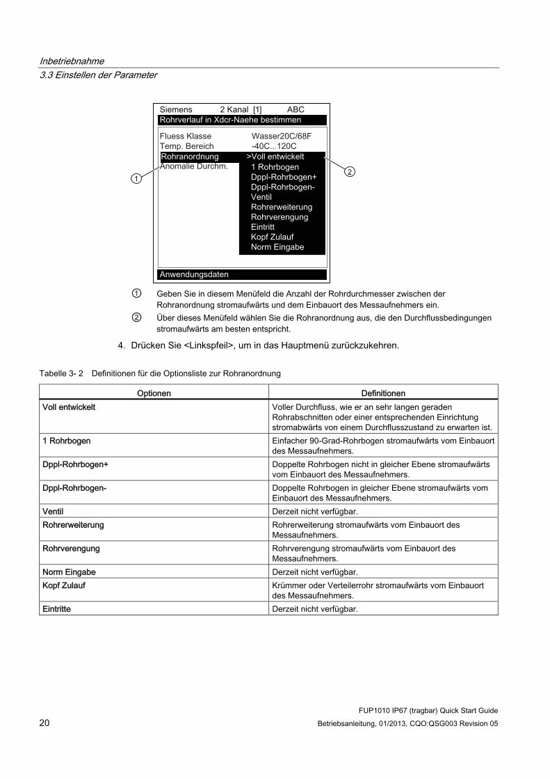
Inbetriebnahme 3.3 Einstellen der Parameter
FUP1010 IP67 (tragbar) Quick Start Guide 20 Betriebsanleitung, 01/2013, CQO:QSG003 Revision 05
① Geben Sie in diesem Menüfeld die Anzahl der Rohrdurchmesser zwischen der
Rohranordnung stromaufwärts und dem Einbauort des Messaufnehmers ein. ② Über dieses Menüfeld wählen Sie die Rohranordnung aus, die den Durchflussbedingungen
stromaufwärts am besten entspricht.
4. Drücken Sie <Linkspfeil>, um in das Hauptmenü zurückzukehren.
Tabelle 3- 2 Definitionen für die Optionsliste zur Rohranordnung
Optionen Definitionen Voll entwickelt Voller Durchfluss, wie er an sehr langen geraden
Rohrabschnitten oder einer entsprechenden Einrichtung stromabwärts von einem Durchflusszustand zu erwarten ist.
1 Rohrbogen Einfacher 90-Grad-Rohrbogen stromaufwärts vom Einbauort des Messaufnehmers.
Dppl-Rohrbogen+ Doppelte Rohrbogen nicht in gleicher Ebene stromaufwärts vom Einbauort des Messaufnehmers.
Dppl-Rohrbogen- Doppelte Rohrbogen in gleicher Ebene stromaufwärts vom Einbauort des Messaufnehmers.
Ventil Derzeit nicht verfügbar. Rohrerweiterung Rohrerweiterung stromaufwärts vom Einbauort des
Messaufnehmers. Rohrverengung Rohrverengung stromaufwärts vom Einbauort des
Messaufnehmers. Norm Eingabe Derzeit nicht verfügbar. Kopf Zulauf Krümmer oder Verteilerrohr stromaufwärts vom Einbauort
des Messaufnehmers. Eintritte Derzeit nicht verfügbar.

Inbetriebnahme 3.3 Einstellen der Parameter
FUP1010 IP67 (tragbar) Quick Start Guide Betriebsanleitung, 01/2013, CQO:QSG003 Revision 05 21
Kennzeichnung der Messaufnehmer Die Teilenummer auf der Vorderseite stellt die eindeutige Kennzeichnung des Messaufnehmers dar. So bedeutet beispielsweise die Teilenummer 1011PPS-D1 bedeutet:
1011PPS - D1
① Modell ② Größe
Hinweis
Vergewissern Sie sich, dass es sich bei den Messaufnehmern um ein zusammengehöriges, werkseitig abgestimmtes Paar mit der gleichen Seriennummer und den Zusatzkennungen “A” und “B” (z. B. 19256Aund 19256B) handelt.
Hinweis
Die Modellbezeichnungen der Messaufnehmer für Betriebssystemversion 3 lauten wie folgt: 1011H Präzisionsmessaufnehmer, 1011 Universal und 991 Universal.
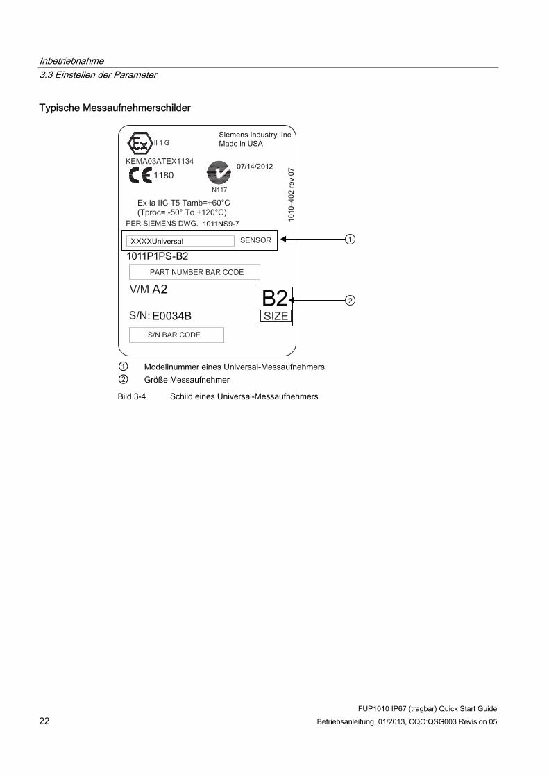
Inbetriebnahme 3.3 Einstellen der Parameter
FUP1010 IP67 (tragbar) Quick Start Guide 22 Betriebsanleitung, 01/2013, CQO:QSG003 Revision 05
Typische Messaufnehmerschilder
① Modellnummer eines Universal-Messaufnehmers ② Größe Messaufnehmer
Bild 3-4 Schild eines Universal-Messaufnehmers

Inbetriebnahme 3.3 Einstellen der Parameter
FUP1010 IP67 (tragbar) Quick Start Guide Betriebsanleitung, 01/2013, CQO:QSG003 Revision 05 23
① Modellnummer eines Präzisions-Messaufnehmers ② Größe Messaufnehmer
Bild 3-5 Schild eines Präzisions-Messaufnehmers
Auswahl der Messaufnehmer Im Folgenden wird der typische Ablauf einer Messaufnehmerinstallation beschrieben.
1. Drücken Sie den <Linkspfeil>, um in das Hauptmenü zurückzukehren. Drücken Sie im Menü [Funktionsart] den <Rechtspfeil> und anschließend <ENTER>.
2. Das Menü [Einst. Kanal] wird angezeigt.
3. Betätigen Sie den <Abwärtspfeil> zum Auswählen des Menüs [Messaufnehmer installieren].
4. Drücken Sie <Rechtspfeil> für [Transducermodell]. Drücken Sie den <Rechtspfeil> und wählen Sie die auf dem Messaufnehmerschild angegebene Messaufnehmer-Modellnummer aus.

Inbetriebnahme 3.3 Einstellen der Parameter
FUP1010 IP67 (tragbar) Quick Start Guide 24 Betriebsanleitung, 01/2013, CQO:QSG003 Revision 05
5. Im Dropdown-Menü werden die folgenden Messaufnehmer angezeigt:
– 1011 Universal
– 1011HP-T1 - einsetzbar von -40 bis 120 °C, empfohlen für Durchschnittstemperaturen <40 °C; Standard.
– 1011HP-T2 - einsetzbar von -40 bis 120 °C, empfohlen für Durchschnittstemperaturen >40 °C bis <80 °C; Kennzeichnung als Hochtemperatur-Messaufnehmer.
– 1011HP-T3 - einsetzbar von -40 bis 120 °C, empfohlen für Durchschnittstemperaturen >80 °C bis <120 °C; auf Anfrage.
– 991 Universal
Hinweis
Das Messgerät empfiehlt automatisch einen Messaufnehmer anhand der eingegebenen Anwendungsdaten.
6. Wählen Sie in diesem Beispiel das Messaufnehmermodell, das auf dem Messaufnehmerschild angezeigt wird, und drücken Sie <ENTER>.
① Hier den Transducer-Typ auswählen. ② Hier die Transducer-Größe auswählen. ③ Nach erfolgter Montage des Messaufnehmers [Installation] wählen.
7. Drücken Sie zum Auswählen der Messaufnehmergröße den <Rechtspfeil>. Blättern Sie zu der Messaufnehmergröße, die auf dem Messaufnehmerschild angegeben ist. Drücken Sie <ENTER>.
8. Bei [Messaufnehmer Montageart] drücken Sie den <Rechtspfeil>. Blättern Sie zur Auswahl [Reflekt] oder [Direkt] für die Montageart und drücken Sie dann <ENTER>.
9. WICHTIG: Notieren Sie die Abstandsmethode und den Nummernindex. Diese Daten werden bei der Montage der Messaufnehmer benötigt.
10. Die Messaufnehmer können jetzt montiert werden. Beachten Sie die Montageanweisungen des Messaufnehmers unter Messaufnehmer-Installation (Seite 25) und wählen Sie die gewünschte Montageart aus.
11. Blättern Sie nach der Montage der Messaufnehmer zu [Install. beendet] und wählen Sie [Installation].

Inbetriebnahme 3.4 Messaufnehmer-Installation
FUP1010 IP67 (tragbar) Quick Start Guide Betriebsanleitung, 01/2013, CQO:QSG003 Revision 05 25
3.4 Messaufnehmer-Installation
3.4.1 Allgemeine Informationen
Montagearten "Reflekt" und "Direkt" Die Montagearten Reflekt-Modus und Direkt-Modus werden bei Clamp-on-Messaufnehmern unterstützt. Nach Analyse der Daten, die Sie für Ihre Rohre und Flüssigkeiten eingegeben haben, empfiehlt der Messumformer einen Montagemodus. Dieser Quick Start Guide beschreibt eine typische Installation und Einrichtung des Messaufnehmers im Reflekt-Modus.
Hinweis
Informationen zur Montage im Direkt-Modus finden Sie in der Betriebsanleitung.
Montagezubehör Für die Montage der Messaufnehmer wird folgendes Material und Werkzeug benötigt (zum Großteil im Lieferumfang enthalten):
● Flacher Schraubendreher
● Montagerahmen oder Montageschienen
● Klebeband, Kreide und Lineal oder Maßband
● Metallmontagebänder
● Abstandshalter
● Führungsstück (für Direkt-Montage)
● Ultraschall-Koppelpaste
● Messaufnehmer (zusammengehöriges Paar)
3.4.2 Installation der Messaufnehmer
Reflekt-Montage mit Montagerahmen und Abstandshalter 1. Nach Ermittlung des Abstandsindexwertes über das Installationsmenü bereiten Sie den
für die Montage der Messaufnehmer vorgesehenen Bereich der Rohroberfläche vor.
2. Entfetten Sie die Oberfläche, und entfernen Sie Staub, Korrosion, Rost, abblätternde Farbe usw.
Konsultieren Sie vor Beginn der Montage das unten abgebildete Beispiel für eine Montage im Reflekt-Modus.

Inbetriebnahme 3.4 Messaufnehmer-Installation
FUP1010 IP67 (tragbar) Quick Start Guide 26 Betriebsanleitung, 01/2013, CQO:QSG003 Revision 05
① Optional: Bei Rohren mit größerem
Durchmesser können mehrere Bänder miteinander verbunden werden, so dass sie um das Rohr herum reichen.
⑤ Abstandshalter-Klemme mit Befestigungsschraube
② Montageband, um Montagerahmen herum gelegt
⑥ Abstandshalter (von vorne)
③ Messaufnehmer auf Rohr montiert (in 9-Uhr-Position)
⑦ Metallstift
④ Montagerahmen ⑧ Stellschraube für Montageband
Bild 3-6 Reflekt-Montage mit Montagerahmen und Abstandshalter (Ansicht von vorne)
Hinweis
Ltn mind. 18 mm (0,75")
Menüfeld Ltn Dieses schreibgeschützte Menüfeld zeigt den Abstand zwischen den Vorderseiten der Messaufnehmer entlang der Rohrachse in Inch oder Millimeter an. Bei Montage der Messaufnehmer ohne Montageschiene oder Abstandshalter müssen Sie einen Abstand entsprechend diesem Wert einhalten. Beachten Sie, dass bei der Direkt-Montage an besonders kleinen Rohren diese Zahl auch negativ sein kann, wenn die Messaufnehmerabstände sich überschneiden.

Inbetriebnahme 3.4 Messaufnehmer-Installation
FUP1010 IP67 (tragbar) Quick Start Guide Betriebsanleitung, 01/2013, CQO:QSG003 Revision 05 27
Vorgehensweise zur Installation (vgl. Abbildung) 1. Befestigen Sie auf einer ebenen Oberfläche den Abstandshalter an einem
Montagerahmen so, dass der Anschlagstift der Montagerahmenklemme in die Referenzbohrung auf dem Abstandshalter passt. Ziehen Sie die Befestigungsschraube an.
2. Schieben Sie den zweiten Montagerahmen über das andere Ende des Abstandshalters, und richten Sie die Bohrung für den Nummernindex am Anschlagstift der Klemme aus. Ziehen Sie anschließend die Befestigungsschraube an. Vergewissern Sie sich, dass die abgeschrägten Seiten der beiden Montagerahmen jeweils nach außen zeigen.
3. Legen Sie ein Metallmontageband um das Rohr. Das Band muss so platziert werden, dass die Stellschraube für das Montageband leicht zugänglich bleibt.
4. Positionieren Sie die Konstruktion aus Montagerahmen und Abstandshalter in Höhe der Montagestelle so, dass sie auf der Oberseite des Rohres aufliegt.
5. Schieben Sie das Ende des Montagebands unter die Stellschraube für das Montageband.
6. Führen Sie das Montageband unter der Klemmfeder eines der beiden Montagerahmen hindurch.
7. Ziehen Sie die Stellschraube für das Montageband so weit an, dass das Band zwar gespannt ist, die ganze Konstruktion aber noch um das Rohr herum verschoben werden kann. Wiederholen Sie diese Vorgehensweise mit dem anderen Montagerahmen.
8. Verschieben Sie die Konstruktion um das Rohr herum in ihre endgültige Position an der vorbereiteten Stelle. Achten Sie auf axiale Ausrichtung der Konstruktion entlang des Rohres. (Beachten Sie die Lageskizze zum Messaufnehmer.)
9. Spannen Sie die Montagebänder, bis die Konstruktion fest auf dem Rohr sitzt. Die Bänder jedoch nicht zu fest spannen.

Inbetriebnahme 3.4 Messaufnehmer-Installation
FUP1010 IP67 (tragbar) Quick Start Guide 28 Betriebsanleitung, 01/2013, CQO:QSG003 Revision 05
10. Tragen Sie bei beiden Messaufnehmern einen ca. 3 mm (1/8 Inch) langen, durchgehenden Streifen Koppelpaste mittig in Längsrichtung auf die Kontaktfläche des Messaufnehmers auf.
① F-Stecker ④ Vorderseite ② Abgeschrägte Seite ⑤ Kontaktfläche ③ Messaufnehmer ⑥ Koppelpaste Bild 3-7 Messaufnehmer
① ⑥ Vorderansicht Metallmontageband ② Klemmfeder (nicht bei allen Modellen
vorhanden) ⑦ Hinweis: Abbildung zeigt ein optionales
zweites Montageband. Bei Rohren mit größeren Außendurchmessern (über 30" bzw. 76 cm) ist evtl. zusätzliches Montagematerial erforderlich.
③ Messaufnehmer-Befestigungsschraube
⑧ Abstandshalter-Klemme mit Befestigungsschraube
④ Abstandshalter ⑨ Referenzbohrung des Abstandshalters ⑤ Montagerahmen Serie 1012 ⑩ Platzierung eines Ein-Pfad-
Messaufnehmers in 9-Uhr-Position ⑪ Platzierung von Zwei-Pfad-
Messaufnehmern in 10- und 2-Uhr-Position Bild 3-8 Messaufnehmer-Installation

Inbetriebnahme 3.4 Messaufnehmer-Installation
FUP1010 IP67 (tragbar) Quick Start Guide Betriebsanleitung, 01/2013, CQO:QSG003 Revision 05 29
11. Schieben Sie den Messaufnehmer mit der Rückseite voran in einen der Montagerahmen und richten Sie die abgeschrägte Seite des Messaufnehmers an der abgeschrägten Seite des Montagerahmens aus. Der Messaufnehmer sollte dabei erst mit dem Rohr in Kontakt kommen, wenn er am Anschlag des Montagerahmens anschlägt. Drücken Sie den Messaufnehmer auf das Rohr.
12. Ziehen Sie die Befestigungsschraube des Messaufnehmers so weit an, dass der Messaufnehmer sicher in seiner Position gehalten wird. Wiederholen Sie diese Installationsschritte mit dem anderen Messaufnehmer.
13. Befestigen Sie die Kabel unter Beachtung der Ausrichtung stromaufwärts bzw. stromabwärts gemäß den Kennzeichnungen UP (aufwärts) und DN (abwärts) an den Messaufnehmern und ziehen Sie die Kabel fest. Befestigen Sie die anderen Enden der Kabel an den UP- und DN-Eingängen des Messaufnehmers (siehe folgende Abbildung).
① Messaufnehmer-Kabelanschlüsse ③ Kanal 1 - Messaufnehmer stromaufwärts ② An Messaufnehmerpaar Kanal 2
Durchfluss ④ Kanal 1 - Messaufnehmer stromabwärts
Bild 3-9 Anschließen der Messaufnehmer an das Durchflussmessgerät
3.4.3 Abschluss der Installation 1. Blättern Sie im Menü [Messaufnehmer installieren] zu Option [Install. beendet]. Drücken
Sie Taste <Rechtspfeil> und wählen Sie [Installation]. Drücken Sie <ENTER>. Das Durchflussmessgerät durchläuft die Sendefrequenzen.
2. Beachten Sie im eingeblendeten Fenster die Angabe der gemessenen Schallgeschwindigkeit Vs und prüfen Sie die Angabe auf Richtigkeit (falls korrekte Geschwindigkeit bekannt).
3. Um den Wert für die Schallgeschwindigkeit zu übernehmen, drücken Sie Taste <Abwärtspfeil>.
4. Das Durchflussmessgerät ist jetzt betriebsbereit für die Durchflussmessung. Drücken Sie die Taste <MENU> zweimal, um die Durchflussrate anzuzeigen.

Inbetriebnahme 3.4 Messaufnehmer-Installation
FUP1010 IP67 (tragbar) Quick Start Guide 30 Betriebsanleitung, 01/2013, CQO:QSG003 Revision 05
Bild 3-10 Abschluss der Installation
Bild 3-11 Durchfluss messen
Siehe auch Die Ein-/Ausgangsverdrahtung ist den E/A-Anschlusstabellen (Seite 37) zu entnehmen. Die Vorgehensweise zum Festlegen von Messbereichen wird im Handbuch für das Durchflussmessgerät beschrieben.

4Fehlerbehebung
4.1 Fehlerbehebung Dieser Abschnitt enthält eine Liste von Meldungen, die ausgegeben werden können, und Hinweisen zur jeweiligen Meldung. Die Hinweise umfassen Erläuterungen und z. T. auch empfohlene Maßnahmen zur Fehlerbehebung. Erscheint dennoch ein Problem einmal unlösbar, setzen Sie sich mit den Experten der nächsten Siemens-Vertretung für den Bereich Ultraschall-Durchflussmessung in Verbindung unter: http://www.automation.siemens.com/partner (http://www.automation.siemens.com/partner).
Tabelle 4- 1 Tipps zur Fehlerbehebung
Fehler oder Meldung Wahrscheinliche Ursache Lösung Speicher voll Aufgrund vollständiger Auslastung des
Datalogger-Speichers konnten Messortdaten nicht gespeichert werden.
Löschen Sie nicht mehr benötigte Messortdaten, oder schaffen Sie Speicherplatz im Datalogger-Speicher.
Sp. beschaedigt Beim Zugriffsversuch auf Daten des aktiven Messorts ist ein Speicher-Lesefehler aufgetreten.
Siehe hierzu auch das Reset-Verfahren über F4 in der Betriebsanleitung.
Kanal ohne Einst. Wird angezeigt, wenn ein für eine Operation benötigter Kanal nicht aktiviert werden konnte.
Aktivieren Sie den Kanal [Einst. Kanal - Kanal aktivieren - Ja]. Beachten Sie, dass vor Aktivierung eines Kanals zunächst der Installationsvorgang abgeschlossen sein muss.
Clr Active Memory? Wird angezeigt, wenn während des Einschaltvorgangs die Taste F4 gedrückt und gedrückt gehalten wird.
Mit Funktionstaste F4 wird der Systembetrieb nach einer schwerwiegenden Störung (z. B. durch einen starken Spannungsstoß) wiederhergestellt.
Clr Saved Data? [Clr Saved Data?] wird nur angezeigt, wenn Sie den <Abwärtspfeil> als Antwort auf [Clr Active Memory?] betätigt haben.
Wenn Sie auf [Clr Saved Data?] mit [Ja] antworten, werden ALLE gespeicherten Daten gelöscht. Zum Aufrufen im seriellen RS-232-Modus geben Sie @@@ ein und drücken Sie die <ENTER>-Taste.
<EOT> Erscheint, wenn der Bediener angefordert hat, dass Datalogger-Daten an den Drucker oder auf dem Grafikbildschirm ausgegeben werden sollen, jedoch keine Datalogger-Aufzeichnungen existieren bzw. das Ende einer übertragenen Datei erreicht ist.
Aktivieren Sie den Datalogger.
Keine Messorte - <ENTER> drücken
Erscheint bei dem Versuch, eine Messortkonfiguration abzurufen oder zu löschen, wenn keine gespeicherten Messortkonfigurationen verfügbar sind.
Legen Sie einen Messort an.
Sicherheit Reaktion auf das Ändern zuvor eingegebener Daten, wenn sich der Sicherheitsschalter in der Position [Deaktivieren] befindet oder der Sicherheitscode eingegeben wurde.
Bringen Sie den Schalter in die Position [Aktivieren].
Geben Sie den zuvor festgelegten Sicherheitscode ein.
FUP1010 IP67 (tragbar) Quick Start Guide Betriebsanleitung, 01/2013, CQO:QSG003 Revision 05 31
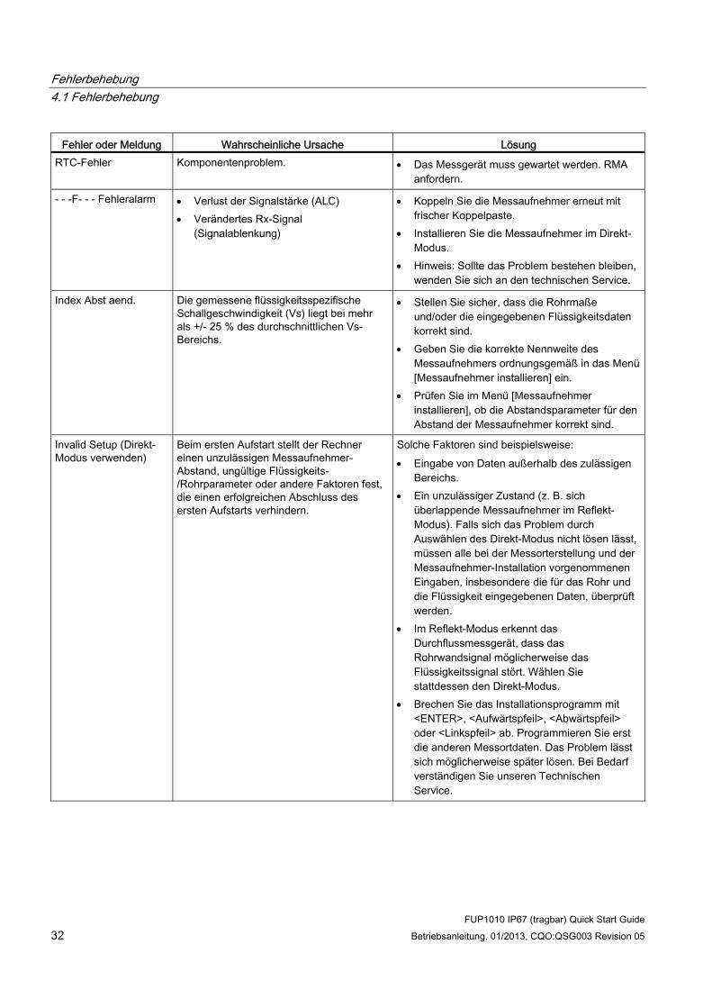
Fehlerbehebung 4.1 Fehlerbehebung
FUP1010 IP67 (tragbar) Quick Start Guide 32 Betriebsanleitung, 01/2013, CQO:QSG003 Revision 05
Fehler oder Meldung Wahrscheinliche Ursache Lösung RTC-Fehler Komponentenproblem. Das Messgerät muss gewartet werden. RMA
anfordern.
- - -F- - - Fehleralarm Verlust der Signalstärke (ALC) Verändertes Rx-Signal
(Signalablenkung)
Koppeln Sie die Messaufnehmer erneut mit frischer Koppelpaste.
Installieren Sie die Messaufnehmer im Direkt-Modus.
Hinweis: Sollte das Problem bestehen bleiben, wenden Sie sich an den technischen Service.
Index Abst aend. Die gemessene flüssigkeitsspezifische Schallgeschwindigkeit (Vs) liegt bei mehr als +/- 25 % des durchschnittlichen Vs-Bereichs.
Stellen Sie sicher, dass die Rohrmaße und/oder die eingegebenen Flüssigkeitsdaten korrekt sind.
Geben Sie die korrekte Nennweite des Messaufnehmers ordnungsgemäß in das Menü [Messaufnehmer installieren] ein.
Prüfen Sie im Menü [Messaufnehmer installieren], ob die Abstandsparameter für den Abstand der Messaufnehmer korrekt sind.
Invalid Setup (Direkt-Modus verwenden)
Beim ersten Aufstart stellt der Rechner einen unzulässigen Messaufnehmer-Abstand, ungültige Flüssigkeits-/Rohrparameter oder andere Faktoren fest, die einen erfolgreichen Abschluss des ersten Aufstarts verhindern.
Solche Faktoren sind beispielsweise: Eingabe von Daten außerhalb des zulässigen
Bereichs. Ein unzulässiger Zustand (z. B. sich
überlappende Messaufnehmer im Reflekt-Modus). Falls sich das Problem durch Auswählen des Direkt-Modus nicht lösen lässt, müssen alle bei der Messorterstellung und der Messaufnehmer-Installation vorgenommenen Eingaben, insbesondere die für das Rohr und die Flüssigkeit eingegebenen Daten, überprüft werden.
Im Reflekt-Modus erkennt das Durchflussmessgerät, dass das Rohrwandsignal möglicherweise das Flüssigkeitssignal stört. Wählen Sie stattdessen den Direkt-Modus.
Brechen Sie das Installationsprogramm mit <ENTER>, <Aufwärtspfeil>, <Abwärtspfeil> oder <Linkspfeil> ab. Programmieren Sie erst die anderen Messortdaten. Das Problem lässt sich möglicherweise später lösen. Bei Bedarf verständigen Sie unseren Technischen Service.

Fehlerbehebung 4.1 Fehlerbehebung
FUP1010 IP67 (tragbar) Quick Start Guide Betriebsanleitung, 01/2013, CQO:QSG003 Revision 05 33
Fehler oder Meldung Wahrscheinliche Ursache Lösung Schwaches Signal - Betätigen Sie <ENTER>
Der Rechner erkennt beim ersten Aufstart, dass das vorhandene Messsignal für einen ordnungsgemäßen Betrieb nicht stark genug ist.
Gründe für ein zu schwaches Signal können z. B. sein: Aufrufen von [Install. beendet] bei leerem Rohr. Koppelpaste nicht ausreichend, nicht
aufgetragen oder eingetrocknet. Koppelpaste erneut auftragen.
Ein Messaufnehmerkabel ist defekt oder hat sich gelöst.
Die Rohroberfläche muss an der Transducer-Montagestelle (erneut) vorbereitet werden (Reinigen usw.).
Große Luftblasen vorhanden. Spülen Sie die Luftblasen aus.
Die Messaufnehmerkabel sind defekt oder am falschen Kanaleingang angeschlossen.
Die Routine [Einstllg Leer] wurde durchgeführt, das Rohr war jedoch NICHT leer.
Falls Sie den Fehler sofort lokalisieren und beheben können, setzen Sie anschließend durch Betätigen von <ENTER> die Installationsroutine fort. Andernfalls brechen Sie die Installationsroutine durch Betätigen des <Linkspfeils> ab und überprüfen die gesamte Messung.
Erkennung Fehler Kann das Durchflussmessgerät den Aufstart nicht durchführen, so lassen die Rohr- und/oder Flüssigkeitsbedingungen kein Empfangssignal zu, das die Anforderungen für eine Berechnung erfüllt. Das System kann nicht in Betrieb genommen werden.
Versuchen Sie, durch Neuinstallation der Messaufnehmer mit geändertem Abstand oder an einer anderen Rohrstelle die richtigen Betriebsbedingungen herzustellen. Eine Lösung ist möglicherweise die Transducer-Montage für den Direkt-Modus statt für den Reflekt-Modus. Es kann aber auch sein, dass der Messbetrieb durch schlechte Schallleitfähigkeit der Rohrwand oder der Flüssigkeit verhindert wird.
Hinweis
Erscheint die Meldung "Erkennung Fehler", empfehlen wir Ihnen, sich von unserem Technischen Service (http://www.automation.siemens.com/partner) beraten zu lassen.

Fehlerbehebung 4.2 Alarmcodes
FUP1010 IP67 (tragbar) Quick Start Guide 34 Betriebsanleitung, 01/2013, CQO:QSG003 Revision 05
4.2 Alarmcodes
Alarmcodes und Beschreibungen Die unten aufgeführten Alarmcodes erscheinen auf der Hauptanzeige des Durchflussmessgeräts.
Buchstabencodes Alarmcode Beschreibung
SPACE Abstand Der Messaufnehmerabstand muss eventuell neu eingestellt werden EMPTY Leerrohr Rohr ist leer HI/LO Durchflussrate Durchfluss über eingestelltem Wert für maximalen Durchfluss bzw. unter Wert
für minimalen Durchfluss FAULT Fehler Drei Sekunden lang keine Aktualisierung durch neue Daten AER Aeration Aktueller Messwert für Luftblasenbildung überschreitet eingestellten
Alarmpegel MEMRY Speicher Letzter gültiger Messwert, der während eines Fehlers über eine festgelegte
Zeitspanne ermittelt wurde MAKUP Neustart Automatischer Aufstart während des Betriebs ist erfolgt
Die folgenden Alarmcodes erscheinen in den Datalogger-Statusmeldungen: I Trennschicht Gemessene Vs der Flüssigkeit überschreitet Alarm-Sollwert für die
Trennschicht P Molchmeld. Durchfahrt von Molch erkannt (Option) Z ZeroMatic ZeroMatic-Signal erkannt
Die folgenden Abbildungen zeigen, an welcher Stelle des Bildschirms die Alarmmeldungen erscheinen. Mit <Aufwärtspfeil> oder <Abwärtspfeil> können die Ansichten umgeschaltet werden.
14.35
354.6597 14.27
100.0
0.031.74
① Alarmcodes

Fehlerbehebung 4.2 Alarmcodes
FUP1010 IP67 (tragbar) Quick Start Guide Betriebsanleitung, 01/2013, CQO:QSG003 Revision 05 35
9/26 12:45
68.10112.3830.0
-30.0
① Alarmcodes

Fehlerbehebung 4.2 Alarmcodes
FUP1010 IP67 (tragbar) Quick Start Guide 36 Betriebsanleitung, 01/2013, CQO:QSG003 Revision 05

AAnhang
A.1 E/A-Anschlüsse und -Verdrahtung
Verdrahtung der Klemmleiste - Verdrahtung des wetterfesten FUP1010 IP67 Zweikanal-/Zweipfad-Durchflussmessgeräts mit Batteriebetrieb
(Siehe Zeichnung 1010WDP-7 im Handbuch, Blatt 2 von 2)
Hinweis
Einkanal-Durchflussmessgeräte haben die gleichen Klemmenanschlussnummern und -signale.
Das Anschlussdiagramm bezieht sich auf die Teilenummern wie nachstehend aufgeführt:
Tabelle A- 1 Teilenummern und Anschlussdaten
Zeichnung 1010WDP-7 (Blatt 2 von 2) FUP1010 7ME3510
FUP1010 IP67 (tragbar) Quick Start Guide Betriebsanleitung, 01/2013, CQO:QSG003 Revision 05 37

Anhang A.1 E/A-Anschlüsse und -Verdrahtung
FUP1010 IP67 (tragbar) Quick Start Guide 38 Betriebsanleitung, 01/2013, CQO:QSG003 Revision 05
Tabelle A- 2 E/A-Klemmleistenverdrahtung Zweikanal-/Zweipfad-Gerät
Stift-Nr. Signal Funktion Beschreibung A GND Signalmasse Signalrückleitung B kA kA Kein Anschluss C R1B Log. Aus 1 Logiksignalpegel (HIGH=5 bis 3 V DC; LOW= 1 bis 0 V DC) D kA kA Kein Anschluss E R2B Log. Aus 2 Logiksignalpegel (HIGH=5 bis 3 V DC; LOW= 1 bis 0 V DC) F kA kA Kein Anschluss G R3B Log. Aus 3 Logiksignalpegel (HIGH=5 bis 3 V DC; LOW= 1 bis 0 V DC) H kA kA Kein Anschluss J R4B Log. Aus 4 Logiksignalpegel (HIGH=5 bis 3 V DC; LOW= 1 bis 0 V DC) K PGEN1 Frequenzausgang 1 Zuweisbare logische Pegelimpulsfolge (5V TTL CMOS-Logik) L PGEN2 Frequenzausgang 2 Zuweisbare logische Pegelimpulsfolge (5V TTL CMOS-Logik) M Vo1 Spannungsausgang 1 Zuweisbar (0 bis 10 V DC) [Min. Lastwiderstand=5 kOhm] N Vo2 Spannungsausgang 2 Zuweisbar (0 bis 10 V DC) [Min. Lastwiderstand=5 kOhm] P Io1 Stromausgang 1 Zuweisbarer Ausgang 4-20 mA
4-20-mA-Ausgänge bieten zudem eine Fehleranzeige, indem sie auf 2 mA abfallen, wenn sie der Durchflussrate zugeordnet sind und eine Fehlerbedingung vorliegt.
R Io2 Stromausgang 2 Zuweisbarer Ausgang 4-20 mA 4-20-mA-Ausgänge bieten zudem eine Fehleranzeige, indem sie auf 2 mA abfallen, wenn sie der Durchflussrate zugeordnet sind und eine Fehlerbedingung vorliegt.
S Io PWR Externer Schleifenstrom Benutzerbeistellung 18 bis 30 V DC @ 25mA min. T GND Signalmasse Signalrückleitung U CNTRL1 Log. Ein 1 TTL-Pegel [HIGH=5 bis 3 V DC; LOW=1 bis 0 V DC] V CNTRL2 Log. Ein 2 TTL-Pegel [HIGH=5 bis 3 V DC; LOW=1 bis 0 V DC] W CNTRL3 Log. Ein 3 TTL-Pegel [HIGH=5 bis 3 V DC; LOW=1 bis 0 V DC] X CNTRL4 Log. Ein 4 TTL-Pegel [HIGH=5 bis 3 V DC; LOW=1 bis 0 V DC] Y Iin1 Stromeingang 1 Externer Gebereingang (4-20 mA) [Lastwiderstand = 250 Ohm]Z Iin2 Stromeingang 2 Externer Gebereingang (4-20 mA) [Lastwiderstand = 250 Ohm]a Vin1 Spannungseingang 1 Externer Gebereingang (0 bis 10 V DC) [Lastwiderstand =
100T Ohm] b Vin2 Spannungseingang 2 Externer Gebereingang (0 bis 10 V DC) [Lastwiderstand =
100T Ohm] c GND Signalmasse Signalrückleitung
Temperaturbereich Schutzart Betrieb: -18 °C bis 60 °C (0 °F bis 140 °F) Lagerung: -20 °C bis 60 °C (-4 °F bis 140 °F)
IP67 (wetterfest))

Anhang A.1 E/A-Anschlüsse und -Verdrahtung
FUP1010 IP67 (tragbar) Quick Start Guide Betriebsanleitung, 01/2013, CQO:QSG003 Revision 05 39
Leistung Die folgenden Leistungsdaten gelten unter Standardbedingungen (d. h. Messungen an einem geraden Rohrverlauf von 15 Durchmessern stromaufwärts und 5 Durchmessern stromabwärts, Durchflussrate über 1 fps, newtonsche Flüssigkeiten ohne Luftblasenbildung mit Reynolds-Zahl <2000 oder >10000).
Tabelle A- 3 Technische Leistungsdaten
Genauigkeit des Laufzeitverfahrens Mindestens 1-2 % des angezeigten Durchflusses (mit Kalibrierung besser als 0,5 % möglich).
Durchflussempfindlichkeit 0,0003 m/s (0,001 fps) - auch bei Nulldurchfluss. Stabilität gegen Nullpunktdrift Weniger als 0,005 m/s (0,015 fps) Reproduzierbarkeit (kleines Volumen) Besser als 0,5 % Ansprechgeschwindigkeit (Dämpfung) SmartSlew wirksam von 0,2 Sekunden bis 5
Minuten. Bereich Durchflussgeschwindigkeit Min. ±12 m/s (±40 ft/s), einschl. Nulldurchfluss Linearität 0,0001 m/s (0,003 ft/s) Strömungsprofilkompensation Automatische Reynoldszahl-Korrektur der
ausgegebenen Durchflussrate.

Anhang A.1 E/A-Anschlüsse und -Verdrahtung
FUP1010 IP67 (tragbar) Quick Start Guide 40 Betriebsanleitung, 01/2013, CQO:QSG003 Revision 05

EBENE A EBENE B EBENE C EBENE D EBENE E EBENE F EBENE G LEBENE H
Funktionsart 2 Kanal Fluss Kanal 1/2 Clamp-on Schnellst.Einst. Wahl Rohrklasse Eingabe aus Liste2Pfad D.fluss Flowtube Rohr waehlen N/AKan 1+2 D.fluss Reflexor Install. Xdcr Transducer Modell Eingabe aus ListeKan 1-2 D.fluss Transducer Gr. Eingabe aus ListeDickenmesser Xdcr Montageart Eingabe aus Liste
Abstandsoffset Eingabe aus ListeNummern Index SchreibgeschütztAbstandsmethode SchreibgeschütztLtn Wert <in> SchreibgeschütztInstall. beendet? Nein/Install Installation wählenLeerrohreinstlg. Eingabe aus ListeNull-Durchfluss Eingabe aus Liste
Volle Ortskonfig Einst. Kanal Messort abrufen Eingabe aus ListeKanal aktivieren Nein/JaAnl/Name Messort Messortnamen eigebenMessprtsicherh. Ein/AusMessort loeschen Eingabe aus ListeOrt sp./umbenenn Messortnamen eingeben/löschen
Rohrdaten Wahl Rohrklasse Eingabe aus ListeRohrgr. Waehlen Eingabe aus ListeRohr AD (in) Numerische EingabeRohrmaterial Eingabe aus Listewanddicke Numerische EingabeBesch.material Eingabe aus ListeBeschicht.dicke Numerische Eingabe
Anwendungsdaten Fluess Klasse Wahl Fluessigk Eingabe aus ListeGeschaetzte Vs Numerische EingabeViskos. (cS) Numerische EingabeDichte S.G. Numerische Eingabe
Temp. Bereich Eingabe aus ListeRohranordnung Eingabe aus ListeAnomalie Durchm Numerische Eingabe
Install. Xdcr Transducer Modell Eingabe aus ListeTransducer Gr. Eingabe aus ListeXdcr Montageart Eingabe aus ListeAbstandsoffset Eingabe aus ListeNummern Index SchreibgeschütztAbstandsmethode SchreibgeschütztLtn Wert SchreibgeschütztInstall. beendet? Nein/Install Installation wählenLeerrohreinstlg. Eingabe aus ListeNull-Durchfluss Eingabe aus Liste
Betriebseinstell Daempf. kontrolle Zeitmittel / SmartSlewTotzone Kontr. Numerische EingabeSp./Fehlere inst Fehler/SpeicherSpeich. verz. (s) Nicht verfuegb.
D.Fluss/Sum Einh D.fluss Vol.einh Eingabe aus ListeD.fluss Zeiteinh Eingabe aus ListeD.fluss Anz. ber. Eingabe aus ListeD.fluss Anz. skal Eingabe aus ListeSumme Vol.einh. Eingabe aus ListeZaehler Skala Eingabe aus ListeZaehleraufloesg. Eingabe aus ListeZaehler Modus Eingabe aus ListeSum Charge/Probe Numerische Eingabe
Messber/Setz/Kal Messbereich Eingabe aus ListeAlarmniv. setzen Eingabe aus ListeKalib. D.fluss Intrinsisch
KcMultiPunkt
Anzeigene inst. Auswahl Daten Eingabe aus ListeDatenanzeige Eingabe aus ListeZeitbasis Eingabe aus ListeLin.diagr loesch Ja/Nein
Loggereinst. Loggermodus Eingabe aus ListeLoggerdaten Eingabe aus ListeLoggerintervall Eingabe aus ListeLoggerereignisse Eingabe aus ListeDisplay Logger Eingabe aus Liste
E/A Datenkontr. Einstellg. AA Eingabe aus ListeRelaiseinstellg. Relais 1,2,3,4Einstellg. AE Eingabe aus Liste
Diagnosedaten D. flussdaten Eingabe aus ListeAnwendungs Info Eingabe aus ListeFluessig.daten Eingabe aus ListeOrtskonf.daten Eingabe aus ListeTesteinrichtung Eingabe aus ListeOrtskonf. drucken Ja/NeinMessort vom (Datum): Schreibgeschützt mm.dd.yy hh.mm.ss
Übersicht Installtionsmenü FUP1010 IP67
3
1
4
2
5
Siemens Industry, Inc.Industry Automation DivisionCoC Ultrasonic FlowHauppauge, New YorkUSAWeb: www.usa.siemens.com
Diese Menü-Übersicht ist gültig für:MLFB - 7ME3510
7ME3511

Übersicht Installtionsmenü FUP1010 IP67EBENE A EBENE B EBENE C EBENE D EBENE E EBENE F
Messeinrichtung Bevorzugte Einh Englisch/MetrischTab. Einstellg. Rohrtbelle Rohr anleg/bearb Eingabe aus Liste
Rohr loeschen Eingabe aus ListeTransducer Typ Eingabe aus Liste
Loggerkontrolle Display Logger Nein/Zeilenumbruch/Kein umruchAusgongslogger Ja/NeinRingspeicher Ja/NeinUebrige Logzeit SchreibgeschütztLogger loeschen Ja/Nein
Speicherkontr. Restl. Logger Sp SchreibgeschütztSpeicherbeleg. Ja/NeinDefragmentieren Ja/Nein
Abgleich AA Abgl Io1 / Io2 Betreiben / Abgl @ 4mAAbgl Vo1 / Vo2 Betreiben / Abgl @ 2VAbgl Pgen1 / Pgen2 Betreiben / Abgl @ 1 kHz
RTD Kalibr. RTD 1 / RTD 2 Werk / Benutzer KalUhr einstellen Datum (MM.DD.YY) Numerische Eingabe
Zeit ((HH.MM) Numerische EingabeRS-232 Einst. Baud Rate Eingabe aus Liste
Paritaet Eingabe aus ListeDatenbits 7/8Zeilenvorschub Ja/NeinNetzwerk ID Numerische EingabeRTS Key Time Eingabe aus Liste
Hintergrundlicht Eingabe aus ListeSystem Info Version Schreibgeschützt
Reset Datum/Zeit Schreibgeschützt mm.dd.yy hh.mm.ssBetr.system P/N SchreibgeschütztPruefsumme SchreibgeschütztCode SchreibgeschütztSystem Zeit Schreibgeschützt mm.dd.yy hh.mm.ss
Sprache Eingabe aus Liste

Sie
men
s In
dust
ry, I
nc.
Indu
stry
Aut
omat
ion
Div
isio
nC
oC U
ltras
onic
Flo
wH
aupp
auge
, New
Yor
k 11
788
USA
Web
: ww
w.us
a.si
emen
s.co
m
KL
AS
SE
AR
oh
r-g
röß
e
3 4 6 8 10 12 14 16 18 20 24 30 36 42 48 54 60 72 84
3.80
0.
39
3.02
4.80
0.
42
3.96
6.90
0.
44
6.02
9.05
0.
46
8.13
11.1
0 0.
50 1
0.10
13.2
0 0.
54 1
2.12
15.3
0 0.
57 1
4.16
17.4
0 0.
60 1
6.20
19.5
0 0.
64 1
8.22
21.6
0 0.
67 2
0.26
25.8
0 0.
76 2
4.28
31.7
4 0.
88 2
9.98
37.9
6 0.
99 3
5.98
44.2
0 1.
10 4
2.00
50.5
0 1.
26 4
7.98
56.6
6 1.
35 5
3.96
62.8
0 1.
39 6
0.02
75.3
4 1.
62 7
2.10
87.5
4 1.
72 8
4.10
AD
W
and
ID
KL
AS
SE
B
3.96
0.
42 3
.12
5.00
0.
45 4
.10
7.10
0.
48 6
.14
9.05
0.
51 8
.03
11.1
0 0.
57 9
.96
13.2
0 0.
62 1
1.96
15.3
0 0.
66 1
3.96
17.4
0 0.
70 1
6.00
19.5
0 0.
75 1
8.00
21.6
0 0.
80 2
0.00
25.8
0 0.
89 2
4.02
32.0
0 1.
03 2
9.94
38.3
0 1.
15 3
6.00
44.5
0 1.
28 4
1.94
50.8
0 1.
42 4
7.96
57.1
0 1.
55 5
4.00
64.4
0 1.
67 6
0.06
76.0
0 1.
95 7
2.10
88.5
4 2.
22 8
4.10
AD
W
and
ID
KL
AS
SE
C
3.96
0.
45 3
.06
5.00
0.
48 4
.04
7.10
0.
51 6
.08
9.30
0.
56 8
.18
11.4
0 0.
62 1
0.16
13.5
0 0.
68 1
2.14
15.6
5 0.
74 1
4.17
17.8
0 0.
80 1
6.20
19.9
2 0.
87 1
8.18
22.0
6 0.
92 2
0.22
26.3
2 1.
04 2
4.22
32.4
0 1.
20 3
0.00
38.7
0 1.
36 3
9.98
45.1
0 1.
54 4
2.02
51.4
0 1.
71 4
7.98
57.8
0 1.
90 5
4.00
64.2
0 2.
00 6
0.20
76.8
8 2.
39 7
2.10
AD
W
and
ID
KL
AS
SE
D
3.96
0.
48 3
.00
5.00
0.
52 3
.96
7.10
0.
55 6
.00
9.30
0.
60 8
.10
11.4
0 0.
68 1
0.04
13.5
0 0.
75 1
2.00
15.6
5 0.
82 1
4.01
17.8
0 0.
89 1
6.02
19.9
2 0.
96 1
8.00
22.0
6 1.
03 2
0.00
26.3
2 1.
16 2
4.00
32.7
4 1.
37 3
0.00
39.1
6 1.
58 3
6.00
45.5
8 1.
78 4
2.02
51.9
8 1.
96 4
8.06
58.4
0 2.
23 5
3.94
64.8
2 2.
38 6
0.06
AD
W
and
ID
KL
AS
SE
E
7.22
0.
58 6
.06
9.42
0.
66 8
.10
11.6
0 0.
74 1
0.12
13.7
8 0.
82 1
2.14
15.9
8 0.
90 1
4.18
18.1
6 0.
98 1
6.20
20.3
4 1.
07 1
8.20
22.5
4 1.
15 2
0.24
26.9
0 1.
31 2
4.28
33.1
0 1.
55 3
0.00
39.6
0 1.
80 3
6.00
AD
W
and
ID
KL
AS
SE
F
7.22
0.
61 6
.00
9.42
0.
71 8
.00
11.6
0 0.
80 1
0.00
13.7
8 0.
89 1
2.00
15.9
8 0.
99 1
4.00
18.1
6 1.
08 1
6.00
20.3
4 1.
17 1
8.00
22.5
4 1.
27 2
0.00
26.9
0 1.
45 2
4.00
33.4
6 1.
73 3
0.00
40.0
4 2.
02 3
6.00
AD
W
and
ID
KL
AS
SE
G
7.38
0.
65 6
.08
9.60
0.
75 8
.10
11.8
4 0.
86 1
0.12
14.0
8 0.
97 1
2.14
16.3
2 1.
07 1
4.18
18.5
4 1.
18 1
6.18
20.7
8 1.
28 1
8.22
23.0
2 1.
39 2
0.24
27.7
6 1.
75 2
4.26
AD
W
and
ID
KL
AS
SE
H
7.38
0.
69 6
.00
9.60
0.
80 8
.00
11.8
4 0.
92 1
0.00
14.0
8 1.
04 1
2.00
16.3
2 1.
16 1
4.00
18.5
4 1.
27 1
6.00
20.7
8 1.
39 1
8.00
23.0
2 1.
51 2
0.00
27.7
6 1.
88 2
4.00
AD
W
and
ID
GU
SS
EIS
EN
RO
HR
- A
WW
A-S
TAN
DA
RD
3.96
4.80
6.90
9.05
11.1
013
.20
15.3
017
.40
19.5
021
.60
25.8
032
.00
38.3
044
.50
50.8
057
.56
KLA
SS
E 5
0N
enn
-d
urc
hm
esse
r
3 4 6 8 10 12 14 16 18 20 24 30 36 42 48 54
/
/
/
/
0.25
6.4
00.
27 8
.51
0.29
10.
520.
31 1
2.58
0.33
14.
640.
34 1
6.72
0.35
18.
800.
36 2
0.88
0.38
25.
040.
39 3
1.22
0.43
37.
440.
47 4
3.56
0.51
49.
780.
57 5
6.42
Wan
d I
D
RO
HR
E A
US
KU
GE
LG
RA
FIT
GU
SS
Ist-
Du
rch
-
mes
ser
(AD
)K
LAS
SE
51
0.25
3.
460.
26
4.28
0.28
6.
340.
30
8.45
0.32
10.
460.
34 1
2.52
0.36
14.
580.
37 1
6.66
0.38
18.
740.
39 2
0.82
0.41
24.
980.
43 3
1.14
0.48
37.
340.
53 4
3.44
0.58
49.
640.
65 5
6.26
Wan
d I
D
KL
AS
SE
52
0.28
3.
400.
29
4.22
0.31
6.
280.
33
8.39
0.35
10.
400.
37 1
2.46
0.39
14.
520.
40 1
6.60
0.41
18.
680.
42 2
0.76
0.44
24.
920.
47 3
1.06
0.53
37.
240.
59 4
3.32
0.65
49.
500.
73 5
6.10
Wan
d I
D
KLA
SS
E 5
3
0.31
3.
340.
32
4.16
0.34
6.
220.
36
8.33
0.38
10.
340.
40 1
2.40
0.42
14.
460.
43 1
6.54
0.44
18.
620.
45 2
0.70
0.47
24.
860.
51 3
0.99
0.58
37.
140.
65 4
3.20
0.72
49.
360.
81 5
5.94
Wan
d I
D
KL
AS
SE
54
0.34
3.
280.
35
4.10
0.37
6.
160.
39
8.27
0.41
10.
280.
43 1
2.34
0.45
14.
400.
46 1
6.48
0.47
18.
560.
48 2
0.64
0.50
24.
800.
55 3
0.90
0.63
37.
040.
71 4
3.08
0.79
49.
220.
89 5
5.78
Wan
d I
D
KL
AS
SE
55
0.37
3.
220.
38
4.04
0.40
6.
100.
42
8.21
0.44
10.
220.
46 1
2.28
0.48
14.
340.
49 1
6.42
0.50
18.
500.
51 2
0.58
0.53
24.
740.
59 3
0.82
0.68
36.
940.
77 4
2.96
0.86
49.
080.
97 5
5.62
Wan
d I
D
0.40
3.
160.
41
3.98
0.43
6.
040.
45
8.15
0.47
10.
160.
49 1
2.22
0.51
14.
280.
52 1
6.36
0.53
18.
440.
54 2
0.52
0.56
24.
680.
63 3
0.74
0.73
36.
840.
83 4
2.84
0.93
48.
941.
05 5
5.46
Wan
d I
D
KL
AS
SE
56
0.12
50.
250
0.12
50.
250
0.12
50.
250
0.12
50.
250
0.12
50.
250
0.12
50.
250
0.18
750.
375
0.18
750.
375
0.18
750.
375
0.18
750.
375
0.18
750.
375
0.25
00.
500
0.25
00.
500
0.25
00.
500
0.25
00.
500
0.25
00.
500
Ein
fach
D
op
pel
tB
esch
ich
tun
g (Z
emen
t)
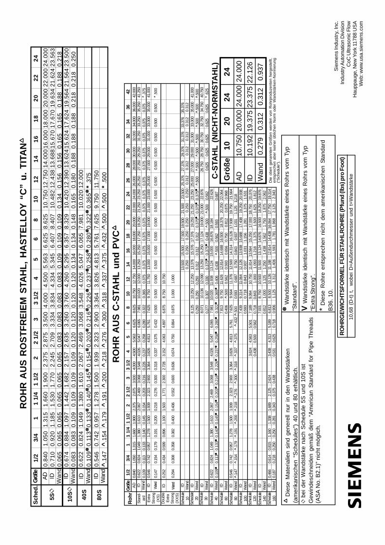
RO
HR
GE
WIC
HT
SF
OR
ME
L F
ÜR
STA
HL
RO
HR
E (P
fun
d (l
bs)
pro
Fo
ot)
10,6
8 (D
-t) t,
w
obei
D=A
ußen
durc
hmes
ser
und
t=W
ands
tärk
e
Die
se M
ater
ialie
n si
nd g
ener
ell n
ur in
den
Wan
dstä
rken
(am
erik
anis
chen
“S
ched
ules
”) 4
0 un
d 80
erh
ältli
ch.
| b
ei d
er W
ands
tärk
e na
ch S
ched
ule
5S u
nd 1
0S is
tG
ewin
desc
hnei
den
gem
äß d
em “
Am
eric
an S
tand
ard
for
Pip
e Th
read
s(A
SA
No.
B2.
1)” n
icht
mög
lich.
Wan
dstä
rke
iden
tisch
mit
Wan
dstä
rke
eine
s R
ohrs
vom
Typ
“Sta
ndar
d”.
V W
ands
tärk
e id
entis
ch m
it W
ands
tärk
e ei
nes
Roh
rs v
om T
yp“E
xtra
Stro
ng”.
* D
iese
Roh
re e
ntsp
rech
en n
icht
dem
am
erik
anis
chen
Sta
ndar
dB
36. 1
0.
24.0
0023
.563
0.21
823
.500
0.25
0
Sch
ed.
0.84
01.
050
0.71
00.
920
0.06
50.
065
0.67
40.
884
0.08
30.
083
0.62
20.
824
0.10
90.
113
0.54
60.
742
^.1
47^
.154
1/2
3/4
RO
HR
AU
S R
OS
TF
RE
IEM
STA
HL
, H
AS
TE
LL
OY
“C
” u
. T
ITA
NG
röße
AD IDW
and
IDW
and
5S|
10
S|
40
S
80
S
IDW
and
IDW
and
1.31
51.
660
1.18
51.
530
0.06
50.
065
1.09
71.
442
0.10
90.
109
1.04
91.
380
0.13
30.
140
0.95
71.
278
^.1
79^
.191
11
1/4
1.90
02.
375
1.77
02.
245
0.06
50.
065
1.68
22.
157
0.10
90.
109
1.61
02.
067
0.14
50.
154
1.50
01.
939
^.2
00^
.218
1 1/
22
2.87
53.
500
2.70
93.
334
0.08
30.
083
2.63
53.
260
0.12
00.
120
2.46
93.
068
0.20
30.
216
2.32
32.
900
^.2
76^
.300
2 1/
23
4.00
04.
500
3.83
44.
334
0.08
30.
083
3.76
04.
260
0.12
00.
120
3.54
84.
026
0.22
60.
237
3.36
43.
826
^.3
18^
.337
3 1/
24
5.56
36.
625
5.34
56.
407
0.10
90.
109
5.29
56.
357
0.13
40.
134
5.04
76.
065
0.25
80.
280
4.81
35.
761
^.3
75^
.432
56
8.62
510
.750
8.40
710
.482
0.10
90.
134
8.32
910
.420
0.14
80.
165
7.98
110
.020
0.32
20.
365
7.62
59.
750
^.5
00^
.500
81
0
12.7
5014
.000
12.4
3813
.688
0.15
60.
156
12.3
9013
.624
0.18
00.
188
12.0
00*
.375
11.7
50*
.500
12
14
16.0
0018
.000
15.6
7017
.670
0.16
50.
165
15.6
2417
.624
0.18
80.
188
16
18
20.0
0022
.000
19.6
3421
.624
0.18
80.
188
19.5
6421
.564
0.21
80.
218
20
22
24
7.00
1 8
.750
10.5
0011
.500
13.1
2414
.876
16.5
0018
.250
19.8
76
3.62
44.
563
5.50
17.
189
9.06
410
.750
11.8
1413
.564
15.2
5017
.000
18.7
5020
.376
7.43
9 9
.314
11.0
6412
.126
13.9
3815
.688
17.4
3819
.250
20.9
38
7.81
3 9
.750
11.6
2612
.814
14.6
8816
.500
18.3
7620
.250
22.0
64
AD IDW
and
Ro
hr
1/2
RO
HR
AU
S C
-STA
HL
un
d P
VC
Grö
ße
ID ID Wan
d
11
1/2
2 1/
24
6
Stan
d-ar
dID
Extra
Stro
ng(X
S)
.̂147
^.1
54^
.179
.̂191
.̂200
^.2
18.̂2
76.̂3
00.̂3
18^
.337
.̂375
^.4
32 ̂
.500
0.59
30.
687
0.75
00.
843
0.93
71.
031
1.12
51.
218
Dou
ble
Extra
Stro
ng(X
XS)
Wan
d
Wan
d
ID Wan
dID Wan
dID Wan
dID Wan
dSc
hedu
le60
ID Wan
dSc
hedu
le80
ID Wan
dID Wan
dSc
hedu
le12
0ID Wan
dSc
hedu
le14
0ID Wan
dSc
hedu
le16
0
3/4
0.84
01.
050
1.31
51.
660
1.90
02.
375
2.87
53.
500
4.00
04.
500
5.56
36.
625
8.62
510
.750
12.7
5014
.000
16.0
0018
.000
20.0
0022
.000
24.0
0026
.000
28.0
0030
.000
32.0
0034
.000
36.0
0042
.000
0.10
90.
113
0.13
30.
140
0.14
50.
154
0.20
30.
216
0.22
60.
237
0.25
80.
280
0.32
20.
365
0.40
60.
438
^.5
000.
562
0.59
30.
687
0.25
00.
250
0.25
00.
312
0.31
20.
312
0.37
50.
375
0.37
5.̂5
00^
.500
^.5
00^
.500
.̂500
^.5
00.̂5
00
1 1/
42
33
1/2
58
1012
1416
1824
2826
3032
3436
4220
22
0.62
20.
824
1.04
91.
380
1.61
02.
067
2.46
93.
068
3.54
84.
026
5.04
76.
065
7.98
110
.020
12.0
0013
.250
15.2
5017
.250
19.2
5021
.250
23.2
5025
.250
27.2
5029
.250
31.2
5033
.250
35.2
5041
.250
0.10
90.
113
0.13
30.
140
0.14
50.
154
0.20
30.
216
0.22
60.
237
0.25
80.
280
0.32
2 0
.365
0.3
75 0
.375
0.3
75 0
.375
0.3
75 0
.375
0.3
75 0
.375
0.3
75 0
.375
0.37
50.
375
0.37
5* .
375
0.54
60.
742
0.95
71.
278
1.50
01.
939
2.32
32.
900
3.36
43.
826
4.81
35.
761
7.62
5 9
.750
11.7
5013
.000
15.0
0017
.000
19.0
0021
.000
23.0
0025
.000
27.0
0029
.000
31.0
0033
.000
35.0
0041
.000
0.14
70.
154
0.17
90.
191
0.20
00.
218
0.27
60.
300
0.31
80.
337
0.37
50.
432
0.50
0 0
.500
0.5
00 0
.500
0.5
00 0
.500
0.5
00 0
.500
0.5
00 0
.500
0.5
00 0
.500
0.50
00.
500
0.50
0* .
500
0.25
20.
434
0.59
90.
896
1.10
01.
503
1.77
12.
300
2.72
83.
152
4.06
34.
897
6.87
5 8
.750
10.7
50
0.29
40.
308
0.35
80.
382
0.40
00.
436
0.55
20.
600
0.63
60.
674
0.75
00.
864
0.87
5 1
.000
1.0
00
13.5
0015
.500
17.5
0019
.500
21.5
0023
.500
25.3
7627
.376
29.3
7631
.376
33.3
7635
.376
0.2
50 0
.250
0.2
50 0
.250
0.2
50 0
.250
0.3
12 0
.312
0.3
12 0
.312
0.3
12 0
.312
8.12
510
.250
12.2
5013
.376
15.3
7617
.376
19.2
5021
.250
23.2
5025
.000
27.0
0029
.000
31.0
0033
.000
35.0
0041
.000
8.07
110
.136
12.0
9013
.250
15.2
5017
.124
19.0
0021
.000
22.8
7626
.750
28.7
5030
.750
32.7
5034
.750
40.7
500.
277
0.30
70.
330
0.37
50.
375
0.43
8^
.500
^.5
000.
562
0.62
50.
625
0.62
50.
625
0.62
5* .
625
0.62
20.
824
1.04
91.
380
1.61
02.
067
2.46
93.
068
3.54
84.
026
5.04
76.
065
7.98
110
.020
11.9
3813
.124
15.0
0016
.876
18.1
8422
.626
0.40
6 ̂
.500
0.5
62 0
.593
0.6
56 0
.750
0.8
12 0
.875
0.9
680.
546
0.74
20.
957
1.27
81.
500
1.93
92.
323
2.90
03.
364
3.82
64.
813
5.76
17.
625
9.5
6411
.376
12.5
0014
.314
16.1
2617
.938
19.7
5021
.564
0.59
3 0
.718
0.8
43 0
.937
1.0
31 1
.156
1.2
81 1
.375
1.5
31
0.43
80.
500
0.56
20.
718
0.84
3 1
.000
1.0
93 1
.218
1.3
75 1
.500
1.6
25 1
.812
0.81
2 1
.000
1.1
25 1
.250
1.4
38 1
.562
1.7
50 1
.875
2.0
620.
466
0.61
40.
815
1.16
01.
338
1.68
92.
125
2.62
43.
438
4.31
35.
189
6.81
3 8
.500
10.1
2611
.188
12.8
1414
.438
16.0
6417
.750
19.3
140.
187
0.21
80.
250
0.25
00.
281
0.34
30.
375
0.43
80.
531
0.62
50.
718
0.90
6 1
.125
1.3
12 1
.406
1.5
93 1
.781
1.9
68 2
.125
2.3
43
Grö
ße
10
20
24
24
AD10
.750
20.0
0024
.000
24.0
00ID
10.1
9219
.375
23.3
7522
.126
Wan
d0.
279
0.31
20.
312
0.93
7D
ie o
ben
gena
nnte
n G
röße
n w
erde
n vo
n R
ohrp
rodu
zent
en h
erge
stel
lt,en
tspr
eche
n ab
er k
eine
r üb
liche
n N
orm
ode
r W
ands
tärk
en-N
orm
ieru
ng(“S
ched
ule”
).
C-S
TAH
L (
NIC
HT
-NO
RM
STA
HL
)
Sche
dule
10Sc
hedu
le20
Sche
dule
30Sc
hedu
le40
Sche
dule
100
Sie
men
s In
dust
ry, I
nc.
Indu
stry
Aut
omat
ion
Div
isio
nC
oC U
ltras
onic
Flo
wH
aupp
auge
, New
Yor
k 11
788
USA
Web
: ww
w.us
a.si
emen
s.co
m

Sonic Velocity Relative to Temperature of Pure Water Temperature Velocity Temperature Velocity Temperature Velocity F C M/S F C M/S F C M/S 0.0 -17.8 1292.45 100.0 37.8 1525.03 200.0 93.3 1548.38 2.0 -16.67 1300.64 102.0 38.9 1526.99 202.0 94.4 1547.60 4.0 -15.55 1308.63 104.0 40.0 1528.86 204.0 95.6 1546.78 6.0 -14.44 1316.44 106.0 41.1 1530.67 206.0 96.7 1547.60 8.0 -13.33 1324.06 108.0 42.2 1532.4 208.0 97.8 1545.02
10.0 -12.22 1331.50 110.0 43.3 1534.06 210.0 98.9 1544.08 12.0 -11.00 1338.77 112.0 44.4 1535.64 212.0 100.0 1543.11 14.0 -10.0 1345.86 114.0 45.6 1537.16 214.0 101.1 1542.10 16.0 -8.89 1352.78 116.0 46.7 1538.61 216.0 102.2 1541.05 18.0 -7.78 1359.53 118.0 47.8 1539.99 218.0 103.3 1539.97 20.0 -6.67 1366.12 120.0 48.9 1541.30 220.0 104.4 1538.85 22.0 -5.56 1372.55 122.0 50.0 1542.55 222.0 105.6 1537.70 24.0 -4.44 1378.82 124.0 51.1 1543.74 224.0 106.7 1536.51 26.8 -3.33 1384.94 126.0 52.2 1544.86 226.0 107.8 1535.29 28.0 -2.22 1390.90 128.0 53.3 1545.91 228.0 108.9 1534.03 30.0 -1.11 1396.72 130.0 54.4 1546.91 230.0 110.0 1532.74 32.0 0.0 1402.39 132.0 55.6 1547.84 232.0 111.1 1531.42 34.0 1.11 1407.91 134.0 56.7 1548.72 234.0 112.2 1530.06 36.0 2.22 1413.30 136.0 57.8 1549.53 236.0 113.3 1528.67 38.0 3.33 1418.55 138.0 58.9 1550.29 238.0 114.4 1527.26 40.0 4.44 1423.66 140.0 60.0 1550.99 240.0 115.6 1525.81 42.0 5.56 1428.64 142.0 61.1 1551.63 242.0 116.7 1524.33 44.0 6.67 1433.48 144.0 62.2 1552.21 244.0 117.8 1522.83 46.0 7.78 1438.20 146.0 63.3 1552.74 246.0 118.9 1521.29 48.0 8.89 1442.80 148.0 64.4 1553.22 248.0 120.0 1519.73 50.0 10.0 1447.27 150.0 65.6 1553.64 250.0 121.1 1518.14 52.0 11.11 1451.62 152.0 66.7 1554.01 260.0 126.7 1507.00 54.0 12.22 1455.85 154.0 67.8 1554.32 270.0 132.2 1497.00 56.0 13.33 1459.97 156.0 68.9 1554.59 280.0 137.8 1487.00 58.0 14.44 1463.97 158.0 70.0 1554.80 290.0 143.3 1476.00 60.0 .15.56 1467.86 160.0 71.1 1554.98 300.0 148.9 1465.00 62.0 16.67 1471.64 162.0 72.2 1555.07 310.0 154.4 1453.00 64.0 17.89 1475.31 164.0 73.3 1555.13 320.0 160.0 1440.00 66.0 18.89 1478.88 166.0 74.4 1555.15 330.0 165.6 1426.00 68.0 20.0 1482.34 168.0 75.6 1555.11 340.0 171.1 1412.00 70.0 21.1 1485.70 170.0 76.7 1555.03 350.0 176.7 1398.00 72.0 22.2 1488.96 172.0 77.8 1554.90 360.0 182.2 1383.00 74.0 23.3 1492.13 174.0 78.9 1554.72 370.0 187.8 1368.00 76.0 24.4 1495.19 176.0 80.0 1554.49 380.0 193.3 1353.00 78.0 25.6 1498.16 178.0 81.1 1554.22 390.0 198.9 1337.00 80.0 26.7 1501.04 180.0 82.2 1553.91 400.0 204.4 1320.00 82.0 27.8 1503.82 182.0 83.3 1553.55 410.0 210.0 1302.00 84.0 28.9 1506.52 184.0 84.4 1553.14 420.0 215.6 1283.00 86.0 30.0 1509.13 186.0 85.6 1552.70 430.0 221.1 1264.00 88.0 31.1 1511.65 188.0 86.7 1552.21 440.0 226.7 1244.00 90.0 32.2 1514.08 190.0 87.8 1551.67 450.0 232.2 1220.00 92.0 33.3 1516.44 192.0 88.9 1551.10 460.0 237.8 1200.00 94.0 34.4 1518.70 194.0 90.0 1550.48 470.0 243.3 1180.00 96.0 35.6 1520.89 196.0 91.1 1549.82 480.0 248.9 1160.00 98.0 36.7 1523.00 198.0 92.2 1549.12 490.0 254.4 1140.00
Siemens Industry, Inc.Industry Automation Division
CoC Ultrasonic FlowHauppauge, New York 11788 USA
Web: www.usa.siemens.com
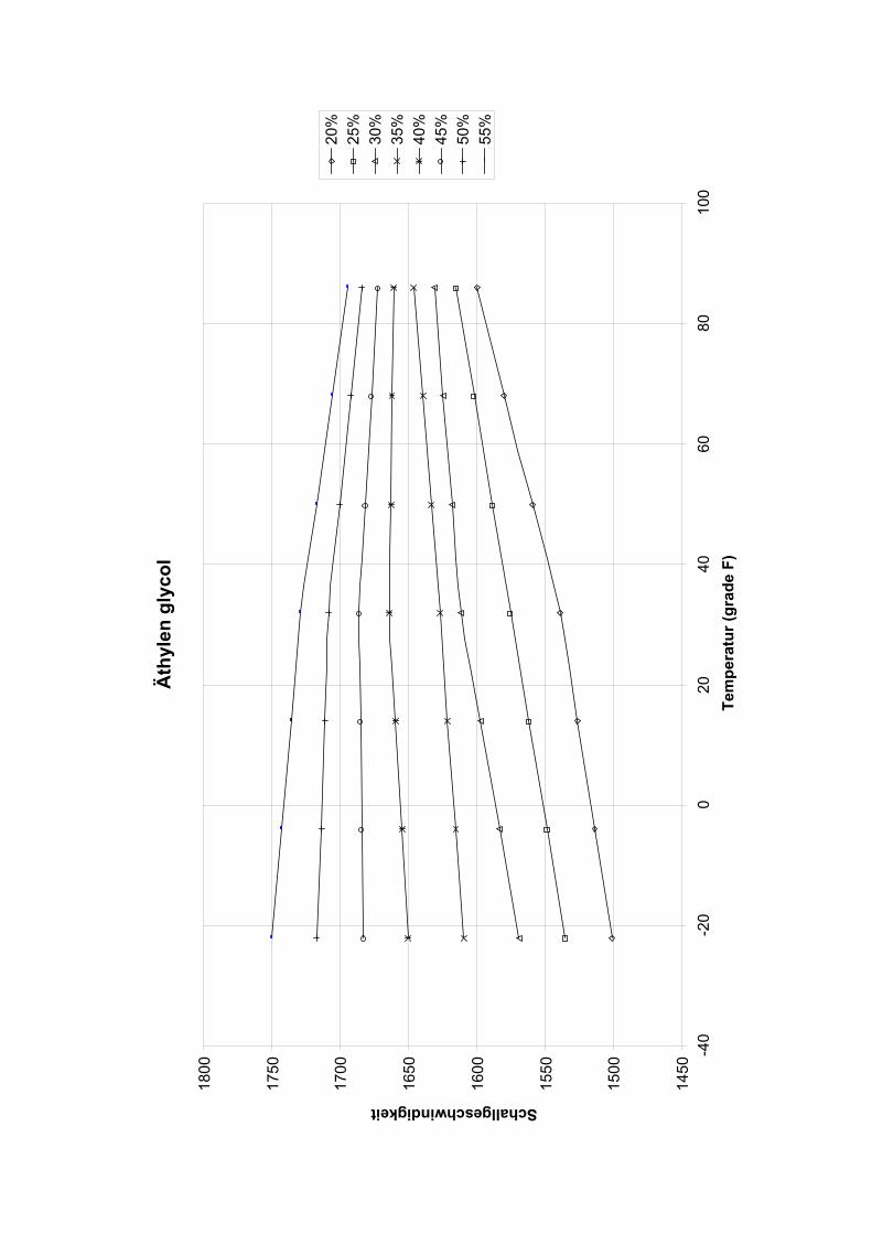
Äth
ylen
gly
col
Schallgeschwindigkeit
1800
1750
1700
1650
1600
1550
1500
1450
-40
55%
50%
45%
40%
35%
30%
25%
20%
-20
080
2040
6010
0Te
mpe
ratu
r (gr
ade
F)

___________________
Guide de mise en route rapide
FUP1010 IP67 portatif
___________________
___________________
___________________
___________________
1Introduction
2Installation
3Mise en service
SITRANS F
4Diagnostic d'erreurs
Débitmètres à ultrasons
AGuide de mise en route rapide FUP1010 IP67 portatif
Annexe
Instructions de service
01/2013 CQO:QSG003 Revision 05

Siemens AG Industry Sector Postfach 48 48 90026 NÜRNBERG ALLEMAGNE
Numéro de référence du document: CQO:QSG003 Ⓟ 02/2013 Sous réserve de modifications techniques
Copyright © Siemens AG 2013. Tous droits réservés
Mentions légales Signalétique d'avertissement
Ce manuel donne des consignes que vous devez respecter pour votre propre sécurité et pour éviter des dommages matériels. Les avertissements servant à votre sécurité personnelle sont accompagnés d'un triangle de danger, les avertissements concernant uniquement des dommages matériels sont dépourvus de ce triangle. Les avertissements sont représentés ci-après par ordre décroissant de niveau de risque.
DANGER signifie que la non-application des mesures de sécurité appropriées entraîne la mort ou des blessures graves.
ATTENTION signifie que la non-application des mesures de sécurité appropriées peut entraîner la mort ou des blessures graves.
PRUDENCE signifie que la non-application des mesures de sécurité appropriées peut entraîner des blessures légères.
IMPORTANT signifie que la non-application des mesures de sécurité appropriées peut entraîner un dommage matériel.
En présence de plusieurs niveaux de risque, c'est toujours l'avertissement correspondant au niveau le plus élevé qui est reproduit. Si un avertissement avec triangle de danger prévient des risques de dommages corporels, le même avertissement peut aussi contenir un avis de mise en garde contre des dommages matériels.
Personnes qualifiées L’appareil/le système décrit dans cette documentation ne doit être manipulé que par du personnel qualifié pour chaque tâche spécifique. La documentation relative à cette tâche doit être observée, en particulier les consignes de sécurité et avertissements. Les personnes qualifiées sont, en raison de leur formation et de leur expérience, en mesure de reconnaître les risques liés au maniement de ce produit / système et de les éviter.
Utilisation des produits Siemens conforme à leur destination Tenez compte des points suivants:
ATTENTION Les produits Siemens ne doivent être utilisés que pour les cas d'application prévus dans le catalogue et dans la documentation technique correspondante. S'ils sont utilisés en liaison avec des produits et composants d'autres marques, ceux-ci doivent être recommandés ou agréés par Siemens. Le fonctionnement correct et sûr des produits suppose un transport, un entreposage, une mise en place, un montage, une mise en service, une utilisation et une maintenance dans les règles de l'art. Il faut respecter les conditions d'environnement admissibles ainsi que les indications dans les documentations afférentes.
Marques de fabrique Toutes les désignations repérées par ® sont des marques déposées de Siemens AG. Les autres désignations dans ce document peuvent être des marques dont l'utilisation par des tiers à leurs propres fins peut enfreindre les droits de leurs propriétaires respectifs.
Exclusion de responsabilité Nous avons vérifié la conformité du contenu du présent document avec le matériel et le logiciel qui y sont décrits. Ne pouvant toutefois exclure toute divergence, nous ne pouvons pas nous porter garants de la conformité intégrale. Si l'usage de ce manuel devait révéler des erreurs, nous en tiendrons compte et apporterons les corrections nécessaires dès la prochaine édition.
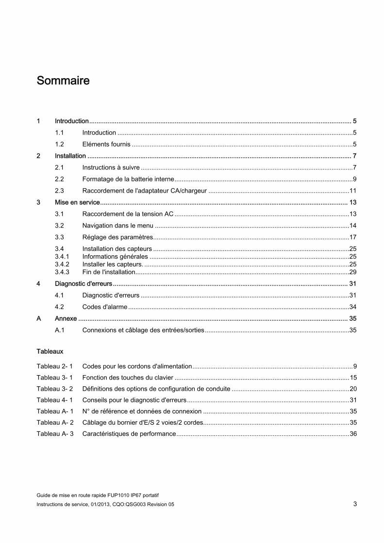
Sommaire
1 Introduction................................................................................................................................................ 5
1.1 Introduction ....................................................................................................................................5
1.2 Eléments fournis ............................................................................................................................5
2 Installation ................................................................................................................................................. 7
2.1 Instructions à suivre .......................................................................................................................7
2.2 Formatage de la batterie interne....................................................................................................9
2.3 Raccordement de l'adaptateur CA/chargeur ...............................................................................11
3 Mise en service........................................................................................................................................ 13
3.1 Raccordement de la tension AC ..................................................................................................13
3.2 Navigation dans le menu .............................................................................................................14
3.3 Réglage des paramètres..............................................................................................................17
3.4 Installation des capteurs ..............................................................................................................25 3.4.1 Informations générales ................................................................................................................25 3.4.2 Installer les capteurs. ...................................................................................................................25 3.4.3 Fin de l'installation........................................................................................................................29
4 Diagnostic d'erreurs................................................................................................................................. 31
4.1 Diagnostic d'erreurs .....................................................................................................................31
4.2 Codes d'alarme ............................................................................................................................34
A Annexe .................................................................................................................................................... 35
A.1 Connexions et câblage des entrées/sorties.................................................................................35
Tableaux
Tableau 2- 1 Codes pour les cordons d'alimentation..........................................................................................9 Tableau 3- 1 Fonction des touches du clavier ..................................................................................................15 Tableau 3- 2 Définitions des options de configuration de conduite ..................................................................20 Tableau 4- 1 Conseils pour le diagnostic d'erreurs...........................................................................................31 Tableau A- 1 N° de référence et données de connexion ..................................................................................35 Tableau A- 2 Câblage du bornier d'E/S 2 voies/2 cordes..................................................................................35 Tableau A- 3 Caractéristiques de performance.................................................................................................36
Guide de mise en route rapide FUP1010 IP67 portatif Instructions de service, 01/2013, CQO:QSG003 Revision 05 3
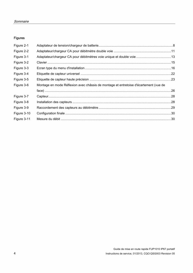
Sommaire
Guide de mise en route rapide FUP1010 IP67 portatif 4 Instructions de service, 01/2013, CQO:QSG003 Revision 05
Figures
Figure 2-1 Adaptateur de tension/chargeur de batterie...................................................................................8 Figure 2-2 Adaptateur/chargeur CA pour débitmètre double voie ................................................................11 Figure 3-1 Adaptateur/chargeur CA pour débitmètres voie unique et double voie .......................................13 Figure 3-2 Clavier ..........................................................................................................................................15 Figure 3-3 Ecran type du menu d'installation ................................................................................................16 Figure 3-4 Etiquette de capteur universel .....................................................................................................22 Figure 3-5 Etiquette de capteur haute précision ...........................................................................................23 Figure 3-6 Montage en mode Réflexion avec châssis de montage et entretoise d'écartement (vue de
face) .............................................................................................................................................26 Figure 3-7 Capteur.........................................................................................................................................28 Figure 3-8 Installation des capteurs ..............................................................................................................28 Figure 3-9 Raccordement des capteurs au débitmètre .................................................................................29 Figure 3-10 Configuration finale ......................................................................................................................30 Figure 3-11 Mesure du débit ...........................................................................................................................30

Introduction 11.1 Introduction
Introduction Le présent guide de mise en route rapide est destiné aux débitmètres portatifs Siemens FUP1010 IP67 résistants aux intempéries. Il comprend les procédures de rodage et de chargement de la batterie et d'utilisation de l'adaptateur de tension CA. Il décrit également une configuration typique utilisant des transducteurs de la série D en mode réflexion (pour le mode direct, référez-vous aux instructions de service). Les procédures décrites s'appliquent également à d'autres modèles à une ou plusieurs voies.
Le programme Siemens Si-Ware d'aide à l'installation du débitmètre est téléchargeable à l'adresse [http://s13.me/ns/cv].
Remarque
Remarque importante concernant la sécurité : Pour les indications importantes relatives à la sécurité et les paramètres complets, référez-vous aux Instructions de service fournies avec l'appareil.
Remarque
Ce guide de mise en route rapide s'applique aux systèmes FUP1010 IP67 (résistants aux intempéries) suivants : version 3.02.02 et versions postérieures, ainsi que version 4.03.00 et versions postérieures
1.2 Eléments fournis ● Transmetteur SITRANS FUS1010 IP65 NEMA 4X & IP66 NEMA 7
● CD avec la documentation SITRANS F
● Guide de mise en route rapide
Remarque
Pour les articles supplémentaires, référez-vous à votre de bordereau de marchandises.
Guide de mise en route rapide FUP1010 IP67 portatif Instructions de service, 01/2013, CQO:QSG003 Revision 05 5

Introduction 1.2 Eléments fournis
Guide de mise en route rapide FUP1010 IP67 portatif 6 Instructions de service, 01/2013, CQO:QSG003 Revision 05
Installation 22.1 Instructions à suivre
Consignes de base ● Déterminez le matériau et les dimensions de la conduite.
● Evitez des conduites verticales avec un débit descendant.
● Si possible, évitez l'installation de capteurs au-dessus et en dessous de conduites horizontales.
● Sélectionnez l'endroit où la conduite possède sa longueur maximale.
● Identifiez la configuration amont de la conduite (coude, réducteur, etc.).
● Il est recommandé que la surface de la conduite soit lisse, et le cas échéant, sans peinture.
● Evitez les composants diminuant la pression en amont.
● Evitez le montage sur ou à proximité des joints de soudure.
● La conduite doit être remplie pour garantir un fonctionnement correct.
Le débitmètre possède un chargeur de batterie optionnel qui fonctionne avec une tension de 100, 110 ou 220 V CA (50 Hz ou 60 Hz). Son entrée de tension universelle n'exige aucune commutation de la part de l'utilisateur. Des câbles de connexion des sorties AS sont livrables en option pour la plupart des pays.
PRUDENCE L'adaptateur/chargeur de batterie 1015BCK-1 n'est PAS étanche ni résistant à l'eau.
Toute exposition à un environnement humide ou immergé entraîne des dommages irréparables à l'appareil et peut exposer l'utilisateur au risque d'électrocution.
Ne pas l'exposer à l'humidité et ne pas l'utiliser s'il est humide.
Guide de mise en route rapide FUP1010 IP67 portatif Instructions de service, 01/2013, CQO:QSG003 Revision 05 7

Installation 2.1 Instructions à suivre
Guide de mise en route rapide FUP1010 IP67 portatif 8 Instructions de service, 01/2013, CQO:QSG003 Revision 05
① Prise d'alimentation IEC 320 ②. Connecteur ③ 0,9 mètres minimum (3 ft) ④ NEMA 5 - 15P (voir tableau des cordons d'alimentation) ⑤ Fiche IEC 320 (voir tableau des cordons d'alimentation)
Figure 2-1 Adaptateur de tension/chargeur de batterie

Installation 2.2 Formatage de la batterie interne
Guide de mise en route rapide FUP1010 IP67 portatif Instructions de service, 01/2013, CQO:QSG003 Revision 05 9
Tableau 2- 1 Codes pour les cordons d'alimentation
Cordon d'alimentation Référence ensemble Standard fiche. Puissance nominale
1015BCA-1 CEE 7/7 10 A / 230 V CA 1015BCC-1 A5 3112 10 A / 250 V CA 1015BCD-1 BS 1363 5 A / 240 V CA 1015BCJ-1 JIS 8303 12 A / 125 V CA 1015BCK-1 NEM 5-15P 10 A / 120 V CA 1015BCL-1 SEV 1011 10 A / 250 V CA
2.2 Formatage de la batterie interne
Fonctionnement sur batterie Tous les systèmes portables comprennent des chargeurs de batterie afin de fonctionner sur une source de tension AC. Il est fortement recommandé de "formater" et de charger la batterie avant de mettre l'appareil en service pour la première fois.
LED témoin de charge Un témoin de charge de la batterie indique l'état des circuits de charge et de la batterie interne. La couleur de la LED témoin commute entre le rouge et le vert en fonction du fonctionnement du débitmètre.
LED Etat de la batterie
Verte Charge d'entretien en cours Rouge Charge rapide en cours (le débitmètre doit être hors tension)
Formatage de la batterie interne Le débitmètre utilise une batterie rechargeable interne conçue pour un cycle de charge rapide (NiMH, 12 V CC, 3 200 mAH). Les batteries doivent être "formatées" pour fournir un temps de fonctionnement optimal, qui est d'environ 7 heures. Cette procédure demande d'effectuer au moins deux cycles complets de charge/décharge.
Remarque
Pour enlever ou remplacer la batterie interne ou la mettre au rebut, reportez-vous au paragraphe Maintenance et service du manuel d'instructions.
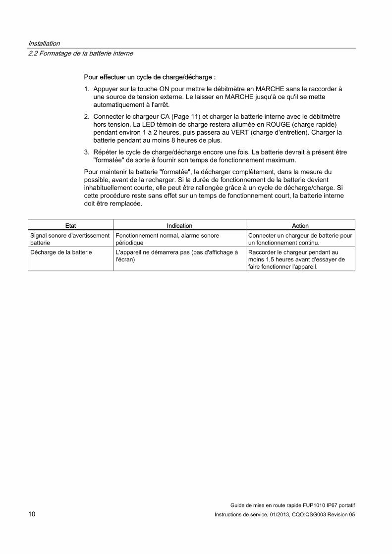
Installation 2.2 Formatage de la batterie interne
Guide de mise en route rapide FUP1010 IP67 portatif 10 Instructions de service, 01/2013, CQO:QSG003 Revision 05
Pour effectuer un cycle de charge/décharge :
1. Appuyer sur la touche ON pour mettre le débitmètre en MARCHE sans le raccorder à une source de tension externe. Le laisser en MARCHE jusqu'à ce qu'il se mette automatiquement à l'arrêt.
2. Connecter le chargeur CA (Page 11) et charger la batterie interne avec le débitmètre hors tension. La LED témoin de charge restera allumée en ROUGE (charge rapide) pendant environ 1 à 2 heures, puis passera au VERT (charge d'entretien). Charger la batterie pendant au moins 8 heures de plus.
3. Répéter le cycle de charge/décharge encore une fois. La batterie devrait à présent être "formatée" de sorte à fournir son temps de fonctionnement maximum.
Pour maintenir la batterie "formatée", la décharger complètement, dans la mesure du possible, avant de la recharger. Si la durée de fonctionnement de la batterie devient inhabituellement courte, elle peut être rallongée grâce à un cycle de décharge/charge. Si cette procédure reste sans effet sur un temps de fonctionnement court, la batterie interne doit être remplacée.
Etat Indication Action
Signal sonore d'avertissement batterie
Fonctionnement normal, alarme sonore périodique
Connecter un chargeur de batterie pour un fonctionnement continu.
Décharge de la batterie L'appareil ne démarrera pas (pas d'affichage à l'écran)
Raccorder le chargeur pendant au moins 1,5 heures avant d'essayer de faire fonctionner l'appareil.

Installation 2.3 Raccordement de l'adaptateur CA/chargeur
Guide de mise en route rapide FUP1010 IP67 portatif Instructions de service, 01/2013, CQO:QSG003 Revision 05 11
2.3 Raccordement de l'adaptateur CA/chargeur
Raccordement de l'adaptateur de tension/chargeur 1015BCK-1 (7ME39404PG00) 1. Raccorder le cordon d'alimentation CA à l'entrée de cordon CA de l'adaptateur/chargeur.
2. Enficher le connecteur de l'adaptateur/chargeur dans le connecteur d'entrée Tension auxiliaire/chargeur de batterie sur la face arrière.
3. Enficher la fiche CA de l'adaptateur/chargeur dans une prise électrique CA.
① Entrée câble AC ⑤ Connecteur d'entrée/sortie ② Connecter au connecteur d'entrée de tension sur la
face arrière ⑥ Port RS-232
③ Capteur de débit voie 2 ⑦ Indicateur d'état de la batterie ④ Capteur de débit voie 1 ⑧ Entrée tension auxiliaire/chargeur
Figure 2-2 Adaptateur/chargeur CA pour débitmètre double voie

Installation 2.3 Raccordement de l'adaptateur CA/chargeur
Guide de mise en route rapide FUP1010 IP67 portatif 12 Instructions de service, 01/2013, CQO:QSG003 Revision 05

3Mise en service
3.1 Raccordement de la tension AC
Raccordement de l'adaptateur/chargeur 1015BCK-1 (7ME39404PG00) 1. Raccorder le câble de tension AC à l'entrée AC de l'adaptateur/chargeur.
2. Enficher le connecteur de l'adaptateur dans le connecteur d'entrée de tension sur la face arrière.
① Entrée câble CA ② Connecter au connecteur d'entrée de tension sur la face arrière ③ Indicateur d'état de la batterie ④ Entrée tension auxiliaire/chargeur
Figure 3-1 Adaptateur/chargeur CA pour débitmètres voie unique et double voie
Guide de mise en route rapide FUP1010 IP67 portatif Instructions de service, 01/2013, CQO:QSG003 Revision 05 13

Mise en service 3.2 Navigation dans le menu
Guide de mise en route rapide FUP1010 IP67 portatif 14 Instructions de service, 01/2013, CQO:QSG003 Revision 05
3. Connecter le chargeur à une sortie de tension AC. Dans un délai de 10 secondes après la mise sous tension, l'écran d'accueil du débitmètre s'allume et le logo de Siemens s'affiche. Cet écran d’accueil indique également la version du logiciel de l’appareil.
① Version du logiciel (x.xx.xx)
4. Appuyez sur la touche <MENU> pour afficher le menu principal.
3.2 Navigation dans le menu
Navigation dans le menu Installation Le diagramme du menu d’installation représente une structure multiniveau divisée en trois colonnes de gauche à droite Niveau A - affiche la liste des principales catégories de menus. Niveau B - affiche les champs de menu affectés au niveau A. Dans les champs de menu du niveau B, vous pouvez entrer des données qui sont affichées en tant que paramètres dans une colonne à droite de l’écran. Niveau C - affiche la liste des données du niveau B
Niveau B Niveau C Rappeler infos.install. site Pompe 1
Pompe 2
Niveau A
Activ. voie Créer/nommer site Securite site Effacer install. site Sauv/Renm.site

Mise en service 3.2 Navigation dans le menu
Guide de mise en route rapide FUP1010 IP67 portatif Instructions de service, 01/2013, CQO:QSG003 Revision 05 15
+-= +
*
F1 F3F2 F4
MENU CLR ENTER
DATALOG
ALTCTRL
HELP
1 2 30
7 8 94 5 6
Figure 3-2 Clavier
Remarque
Utiliser la touche <Flèche gauche> pour revenir au menu précédent.
Tableau 3- 1 Fonction des touches du clavier
Touches Description MENU Activer le menu Installation. ENTER Enregistrer des données numériques, sélectionner dans des listes d’options, etc. Flèches gauche / droite Touches de navigation pour le déplacement du curseur. Flèches haut / bas Identique à <Gauche> et <Droite>. Défilement dans listes d’options et affichages
graphiques. CLR Supprimer des données ou sélectionner des options de listes. Chiffres 0 à 9 Saisir des données numériques. Point décimal Saisir le point décimal dans des données numériques. Opérateurs mathématiques Saisir les 4 opérations mathématiques dans des champs numériques. Touches de fonction F1, F2 et F3
Servent à démarrer/arrêter/réinitialiser le totalisateur.
F4 Attention : utilisée pour la réinitialisation du système pendant la mise sous tension CTRL et ALT Touches de commutation vers d’autres fonctions des touches. DATALOG Déclencher l’enregistrement immédiat des données. Plus et moins [+ / -] Changer le signe d’une valeur numérique.
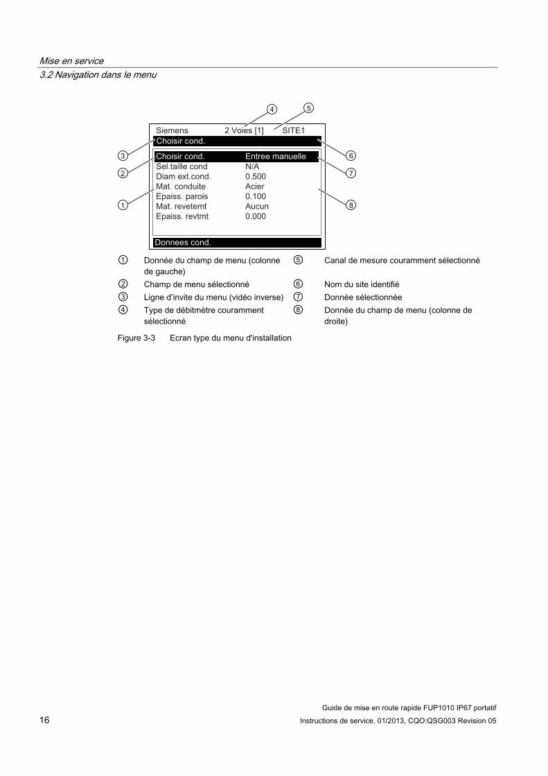
Mise en service 3.2 Navigation dans le menu
Guide de mise en route rapide FUP1010 IP67 portatif 16 Instructions de service, 01/2013, CQO:QSG003 Revision 05
① Donnée du champ de menu (colonne
de gauche) ⑤ Canal de mesure couramment sélectionné
② Champ de menu sélectionné ⑥ Nom du site identifié ③ Ligne d’invite du menu (vidéo inverse) ⑦ Donnée sélectionnée ④ Type de débitmètre couramment
sélectionné ⑧ Donnée du champ de menu (colonne de
droite)
Figure 3-3 Ecran type du menu d'installation

Mise en service 3.3 Réglage des paramètres
Guide de mise en route rapide FUP1010 IP67 portatif Instructions de service, 01/2013, CQO:QSG003 Revision 05 17
3.3 Réglage des paramètres
Sélection de la langue et des unités
Remarque
Avant de créer un site, sélectionner une langue ainsi que les unités britanniques ou métriques dans le menu Equip. Mesureur.
Sélection d'un type de débitmètre 1. Appuyez sur la touche <MENU> et sélectionnez le type de débitmètre.
2. Appuyez sur <Flèche droite> et faites défiler le curseur jusqu’à [Debit 2 voies].
Remarque
Sélectionnez [Debit 2 voies] pour mesurer deux conduites différentes et [Debit 2 cordes] si les capteurs sont montés sur la même conduite.
3. Appuyez sur <ENTER> pour confirmer la sélection. Appuyez sur <Flèche droite> pour sélectionner la fonction du débitmètre. Appuyez sur <ENTER>.
① Sélection pour mesurer deux conduites différentes. (Pas disponible pour tous les modèles.) ② Sélection si deux capteurs sont montés sur la même conduite. ③ Sélection pour l’addition ou la soustraction du débit de deux conduites différentes.
Création d'un site 1. Avant de commencer, assurez-vous que les unités britanniques ou métriques ont été
sélectionnées.
2. Dans le menu [Install. voie], appuyez sur <Flèche droite> et entrez un nom de site.
3. Appuyez sur <ENTER> pour créer le nom de site (par ex. ABC). (Voir la figure ci-dessous.)

Mise en service 3.3 Réglage des paramètres
Guide de mise en route rapide FUP1010 IP67 portatif 18 Instructions de service, 01/2013, CQO:QSG003 Revision 05
Remarque
Pour sélectionner les unités britanniques ou métriques : Dans le menu Type mesureur, faites défiler le curseur jusqu’au menu Equip. mesureur Appuyez sur <Flèche droite> et sélectionnez les unités souhaitées. Appuyez sur <ENTER> pour confirmer la sélection. Appuyez sur <Flèche gauche> et <Flèche haut> pour revenir au menu Type mesureur.
Remarque
Pour sélectionner des lettres : appuyez sur <Flèche droite> pour positionner le curseur sur les lettres ou les chiffres souhaités, puis sélectionnez-les avec <Flèche haut/bas>. Appuyez ensuite sur <ENTER>.
① Saisir le nom souhaité (max. 8 caractères).
4. Faites défiler le curseur jusqu’à [Sauv/Renm. site]. Appuyez sur <Flèche droite> puis sur <ENTER> pour enregistrer le site.
5. Appuyez sur <Flèche gauche> et retournez au menu principal.
Sélection du type de conduite 1. Appuyez sur <Flèche droite> pour sélectionner le type de conduite. Appuyez encore une
fois sur <Flèche droite> et faites défiler le curseur jusqu'au type de conduite souhaité.
2. Appuyez sur <ENTER> pour confirmer la sélection.
3. La dimension et les paramètres prédéfinis pour la conduite s’affichent dans les champs
de menu. Appuyez sur <Flèche droite> et faites défiler le curseur jusqu'à la dimension de conduite souhaitée.
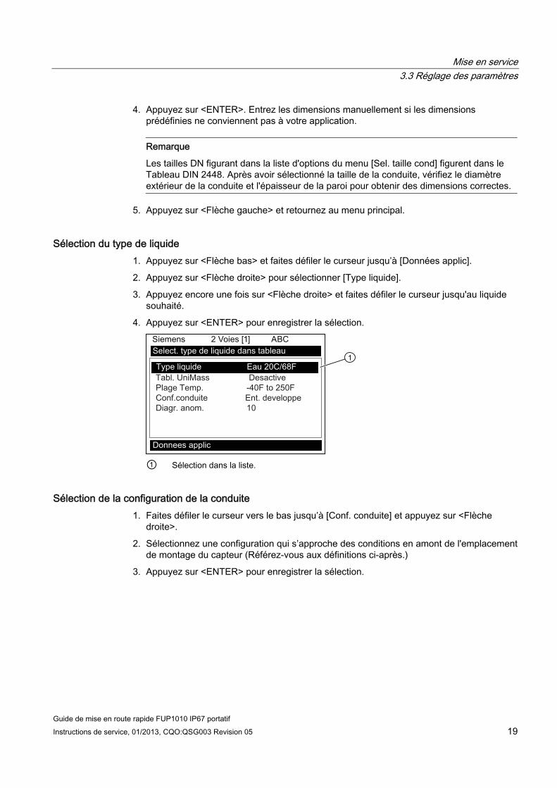
Mise en service 3.3 Réglage des paramètres
Guide de mise en route rapide FUP1010 IP67 portatif Instructions de service, 01/2013, CQO:QSG003 Revision 05 19
4. Appuyez sur <ENTER>. Entrez les dimensions manuellement si les dimensions prédéfinies ne conviennent pas à votre application.
Remarque
Les tailles DN figurant dans la liste d'options du menu [Sel. taille cond] figurent dans le Tableau DIN 2448. Après avoir sélectionné la taille de la conduite, vérifiez le diamètre extérieur de la conduite et l'épaisseur de la paroi pour obtenir des dimensions correctes.
5. Appuyez sur <Flèche gauche> et retournez au menu principal.
Sélection du type de liquide 1. Appuyez sur <Flèche bas> et faites défiler le curseur jusqu’à [Données applic].
2. Appuyez sur <Flèche droite> pour sélectionner [Type liquide].
3. Appuyez encore une fois sur <Flèche droite> et faites défiler le curseur jusqu'au liquide souhaité.
4. Appuyez sur <ENTER> pour enregistrer la sélection.
① Sélection dans la liste.
Sélection de la configuration de la conduite 1. Faites défiler le curseur vers le bas jusqu’à [Conf. conduite] et appuyez sur <Flèche
droite>.
2. Sélectionnez une configuration qui s’approche des conditions en amont de l'emplacement de montage du capteur (Référez-vous aux définitions ci-après.)
3. Appuyez sur <ENTER> pour enregistrer la sélection.

Mise en service 3.3 Réglage des paramètres
Guide de mise en route rapide FUP1010 IP67 portatif 20 Instructions de service, 01/2013, CQO:QSG003 Revision 05
① Dans ce champ de menu, entrez le nombre de diamètres que la conduite possède entre la
configuration amont et la position de montage du capteur. ② Ce champ du menu vous permet de sélectionner la configuration de conduite qui
s’approche le plus des conditions de la conduite en amont.
4. Appuyez sur <Flèche gauche> et retournez au menu principal.
Tableau 3- 2 Définitions des options de configuration de conduite
Options Définitions Ent. développé Débit établi, tel qu’il se produirait dans de très longues
conduites droites ou dans des installations en aval d’une condition de débit.
1 Coude Coude simple à 90 degrés en amont de l'installation du capteur.
Coude dbl+ Coude double à deux niveaux en amont de l'installation du capteur.
Coude dbl- Coude double à un niveau en amont de l'installation du capteur.
Vanne Actuellement non disponible. Extenseur Extension de conduite en amont de l'installation du capteur. Réducteur Réduction de conduite en amont de l'installation du capteur. Entrée nominale Actuellement non disponible. Entrée collect. Collecteur en amont de l'installation du capteur. Intrusions Actuellement non disponible.
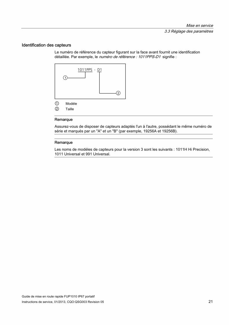
Mise en service 3.3 Réglage des paramètres
Guide de mise en route rapide FUP1010 IP67 portatif Instructions de service, 01/2013, CQO:QSG003 Revision 05 21
Identification des capteurs Le numéro de référence du capteur figurant sur la face avant fournit une identification détaillée. Par exemple, le numéro de référence : 1011PPS-D1 signifie :
1011PPS - D1
① Modèle ② Taille
Remarque
Assurez-vous de disposer de capteurs adaptés l'un à l'autre, possédant le même numéro de série et marqués par un "A" et un "B" (par exemple, 19256A et 19256B).
Remarque
Les noms de modèles de capteurs pour la version 3 sont les suivants : 1011H Hi Precision, 1011 Universal et 991 Universal.

Mise en service 3.3 Réglage des paramètres
Guide de mise en route rapide FUP1010 IP67 portatif 22 Instructions de service, 01/2013, CQO:QSG003 Revision 05
Etiquettes de capteur type
① Numéro de modèle de capteur universel ② Taille du capteur
Figure 3-4 Etiquette de capteur universel

Mise en service 3.3 Réglage des paramètres
Guide de mise en route rapide FUP1010 IP67 portatif Instructions de service, 01/2013, CQO:QSG003 Revision 05 23
① Numéro de modèle de capteur haute précision ② Taille du capteur
Figure 3-5 Etiquette de capteur haute précision
Sélection du capteur La procédure d'installation de capteur type est indiquée ci-après.
1. Utiliser la touche <Flèche gauche> pour revenir au menu principal. Dans le menu [Type mesureur], appuyez sur la touche <Flèche droite>, puis sur <ENTER>.
2. Le menu [Install. voie] s'affiche.
3. Appuyez sur la touche <Flèche bas> pour sélectionner [Install. capteur].
4. Appuyez sur <Flèche droite> pour sélectionner [Modele capteur]. Appuyez sur <Flèche droite> et faites défiler le curseur jusqu'au numéro de modèle de capteur figurant sur l'étiquette du capteur.

Mise en service 3.3 Réglage des paramètres
Guide de mise en route rapide FUP1010 IP67 portatif 24 Instructions de service, 01/2013, CQO:QSG003 Revision 05
5. La liste du menu déroulant permet de choisir l'un des capteurs suivants :
– 1011 Universel
– 1011HP-T1 - Utilisable de -40 à 120 °C, recommandé pour Ø température < 40 °C ; standard.
– 1011HP-T2 - Utilisable de -40 à 120 °C, recommandé pour Ø température > 40 °C - < 80 °C ; décrit comme haute température.
– 1011HP-T3 - Utilisable de -40 à 120 °C, recommandé pour Ø température > 80°C < 120°C ; demande spéciale.
– 991 Universel
Remarque
L'appareil de mesure recommandera automatiquement un capteur en fonction des données d'application qui ont été saisies.
6. Pour cet exemple, sélectionnez le modèle de capteur figurant sur l'étiquette du capteur, puis appuyez sur <ENTER>.
① Sélection basée sur le type. ② Sélection basée sur la taille. ③ Une fois le capteur monté, sélectionnez [Installer].
7. Pour sélectionner la taille du capteur, appuyez sur <Flèche droite>. Faites défiler le curseur pour sélectionner la taille de capteur correspondant à celle indiquée sur l'étiquette du capteur. Appuyez sur <ENTER>.
8. À [Mode mont.capt], appuyez sur <Flèche droite>. Faites défiler le curseur pour sélectionner montage [Reflechir] ou [Direct], puis appuyez sur <ENTER>.
9. IMPORTANT : notez la méthode d'espacement et l'indice numérique. Ces données seront utilisées lors du montage des capteurs.
10. Le montage des capteurs est à présent possible. Reportez-vous aux procédures de montage sous Installation des capteurs (Page 25) et sélectionnez le mode de montage souhaité.
11. Une fois les capteurs montés, faites défiler le curseur jusqu’à [Installt. OK] et sélectionnez [Installer].

Mise en service 3.4 Installation des capteurs
Guide de mise en route rapide FUP1010 IP67 portatif Instructions de service, 01/2013, CQO:QSG003 Revision 05 25
3.4 Installation des capteurs
3.4.1 Informations générales
Modes de montage réflexion et direct Les modes de montage réflexion et direct sont possibles pour les capteurs clamp-on. Le transmetteur recommande un mode de montage après avoir analysé votre conduite et les données que vous avez entrées pour le liquide. Cette mise en route rapide présente une configuration de capteur typique en mode réflexion.
Remarque
Pour le montage direct, référez-vous au manuel Instructions de service.
Accessoires de montage Les éléments suivants sont nécessaires au montage des capteurs (la plupart sont fournis) :
● Tournevis à lame plate
● Châssis de montage ou rails de montage
● Ruban, craie et règle ou mètre à ruban
● Courroies de montage
● Entretoise
● Guide de montage (pour le montage direct)
● Pâte adhérente ultrasonique
● Capteurs (adaptés l'un à l'autre)
3.4.2 Installer les capteurs.
Montage en mode Réflexion avec châssis de montage et entretoise d'écartement 1. Une fois que l'indice d'espacement vous a été fourni par le menu Installation, préparez la
surface de la conduite à l'endroit même où vous allez monter les capteurs.
2. Dégraissez la surface et retirez toute grenaille, corrosion, rouille, écailles de peinture, etc.
Avant de commencer, référez-vous à l'exemple de schéma d'installation du montage réflexion ci-après.
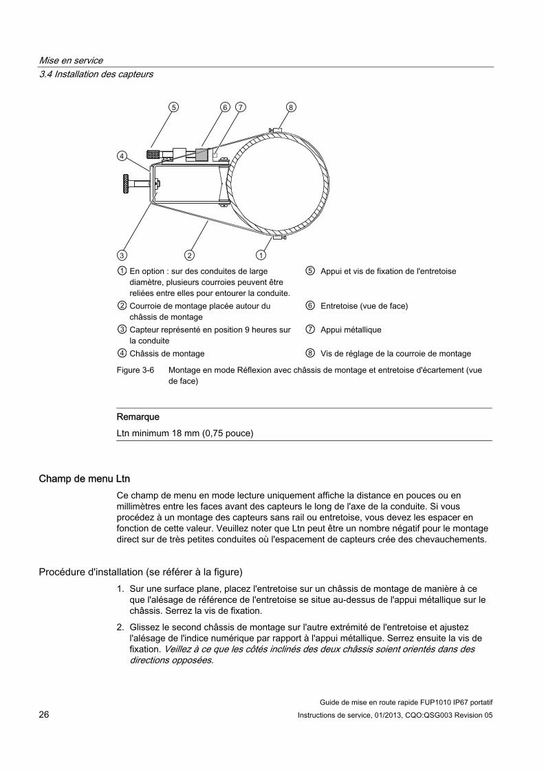
Mise en service 3.4 Installation des capteurs
Guide de mise en route rapide FUP1010 IP67 portatif 26 Instructions de service, 01/2013, CQO:QSG003 Revision 05
① En option : sur des conduites de large
diamètre, plusieurs courroies peuvent être reliées entre elles pour entourer la conduite.
⑤ Appui et vis de fixation de l'entretoise
② Courroie de montage placée autour du châssis de montage
⑥ Entretoise (vue de face)
③ Capteur représenté en position 9 heures sur la conduite
⑦ Appui métallique
④ Châssis de montage ⑧ Vis de réglage de la courroie de montage
Figure 3-6 Montage en mode Réflexion avec châssis de montage et entretoise d'écartement (vue de face)
Remarque
Ltn minimum 18 mm (0,75 pouce)
Champ de menu Ltn Ce champ de menu en mode lecture uniquement affiche la distance en pouces ou en millimètres entre les faces avant des capteurs le long de l'axe de la conduite. Si vous procédez à un montage des capteurs sans rail ou entretoise, vous devez les espacer en fonction de cette valeur. Veuillez noter que Ltn peut être un nombre négatif pour le montage direct sur de très petites conduites où l'espacement de capteurs crée des chevauchements.
Procédure d'installation (se référer à la figure) 1. Sur une surface plane, placez l'entretoise sur un châssis de montage de manière à ce
que l'alésage de référence de l'entretoise se situe au-dessus de l'appui métallique sur le châssis. Serrez la vis de fixation.
2. Glissez le second châssis de montage sur l'autre extrémité de l'entretoise et ajustez l'alésage de l'indice numérique par rapport à l'appui métallique. Serrez ensuite la vis de fixation. Veillez à ce que les côtés inclinés des deux châssis soient orientés dans des directions opposées.

Mise en service 3.4 Installation des capteurs
Guide de mise en route rapide FUP1010 IP67 portatif Instructions de service, 01/2013, CQO:QSG003 Revision 05 27
3. Entourez la conduite d'une courroie de montage. Positionnez-la de sorte que la vis de réglage de la courroie de montage soit facilement accessible.
4. A l'emplacement de montage, placez l'ensemble châssis/entretoise sur la partie supérieure de la conduite.
5. Introduisez l'extrémité de la courroie de montage dans la vis de réglage de la courroie.
6. Faites glisser la courroie sous l'attache à ressort de l’un des châssis de montage.
7. Serrez la vis de la courroie de montage de sorte que la courroie soit tendue, mais que l'ensemble puisse encore tourner autour de la conduite. Procédez de la même manière avec l'autre châssis.
8. Faites tourner l'ensemble autour de la conduite jusqu'à sa position définitive en vous assurant qu'il soit bien rectiligne le long de la conduite (référez-vous au schéma d’orientation du capteur).
9. Serrez les courroies de montage afin de fixer solidement l’ensemble sur la conduite. Ne serrez pas trop fort.

Mise en service 3.4 Installation des capteurs
Guide de mise en route rapide FUP1010 IP67 portatif 28 Instructions de service, 01/2013, CQO:QSG003 Revision 05
10. Prenez chaque capteur et appliquez un boudin continu de pâte adhérente d'environ 3 mm (1/8 pouce) au centre de la surface de contact du capteur.
① Connecteur F ④ Face avant ② Côté incliné ⑤ Surface de contact ③ Capteur ⑥ Pâte adhérente Figure 3-7 Capteur
① ⑥ Vue de face Courroie de montage ② Attache à ressort (n'existe pas sur
tous les modèles) ⑦ Remarque : représentation d'une 2ème
courroie optionnelle. Un support additionnel peut s'avérer nécessaire pour les conduites de diamètre supérieur à 76 cm (30 pouces).
③ Vis de fixation du capteur ⑧ Appui et vis de fixation de l'entretoise ④ Entretoise ⑨ Alésage de référence de l'entretoise ⑤ Châssis de montage série 1012 ⑩ Orientation pour capteur à faisceau unique
en position 9 heures ⑪ Orientation pour capteur à double faisceau
en position 10 heures et 2 heures Figure 3-8 Installation des capteurs

Mise en service 3.4 Installation des capteurs
Guide de mise en route rapide FUP1010 IP67 portatif Instructions de service, 01/2013, CQO:QSG003 Revision 05 29
11. Faites glisser un capteur dans l’un des châssis de montage par l’arrière en alignant son bord oblique avec celui du châssis de montage. Évitez que le capteur ne touche la conduite jusqu'à ce qu'il atteigne la butée du châssis de montage. Poussez le capteur vers le bas afin qu'il adhère à la conduite.
12. Serrez les vis de fixation du capteur afin de maintenir ce dernier fermement en place. Répétez cette procédure pour l’autre capteur.
13. Branchez les câbles UP et DN aux capteurs en respectant l'orientation amont et aval et serrez-les. Branchez les autres extrémités aux bornes UP et DN du débitmètre (voir figure ci-après).
① Connecteurs de câble des capteurs de
débit ③ Voie 1 - Capteur amont
② Vers jeu de capteurs de débit voie 2 ④ Voie 1 - Capteur aval Figure 3-9 Raccordement des capteurs au débitmètre
3.4.3 Fin de l'installation 1. Dans le menu [Installer capteur], faites défiler le curseur vers le bas jusqu'à [Installt. OK].
Appuyez sur <Flèche droite> et sélectionnez [Installer]. Appuyez sur <ENTER>. Le débitmètre explore ses lecteurs.
2. Observez la fenêtre affichant la valeur Vs mesurée et assurez-vous que la vitesse sonique mesurée est correcte (si vous la connaissez).
3. Appuyez sur <Flèche bas> pour accepter la valeur de vitesse sonique.
4. Le débitmètre est à présent prêt à enregistrer le débit. Appuyez deux fois sur la touche <MENU> pour afficher le débit.
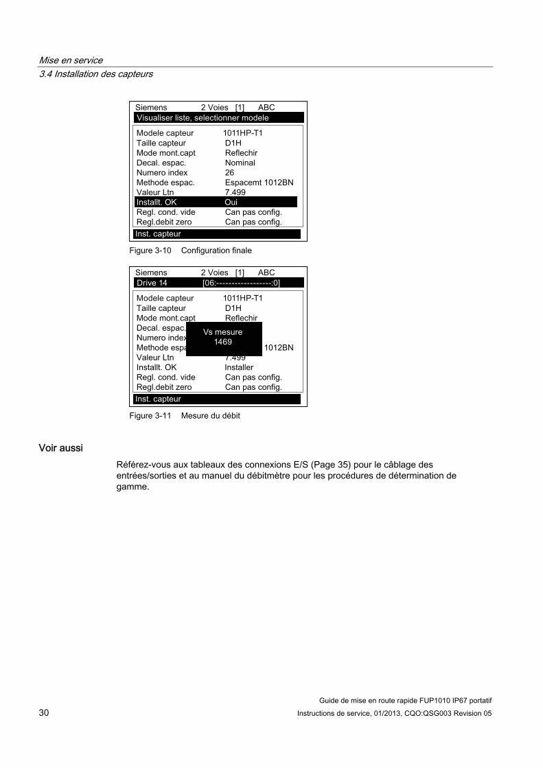
Mise en service 3.4 Installation des capteurs
Guide de mise en route rapide FUP1010 IP67 portatif 30 Instructions de service, 01/2013, CQO:QSG003 Revision 05
Figure 3-10 Configuration finale
Figure 3-11 Mesure du débit
Voir aussi Référez-vous aux tableaux des connexions E/S (Page 35) pour le câblage des entrées/sorties et au manuel du débitmètre pour les procédures de détermination de gamme.

4Diagnostic d'erreurs
4.1 Diagnostic d'erreurs Vous trouverez ci-après la liste des conseils et messages d'éventuels diagnostics d'erreur. Ils comprennent des explications et indiquent parfois l'action recommandée. Si vous êtes face à un problème que vous ne savez pas résoudre, contactez votre agence locale Siemens ou votre représentant régional en charge des débitmètres à ultrasons pour obtenir l'aide de nos experts à : http://www.automation.siemens.com/partner (http://www.automation.siemens.com/partner).
Tableau 4- 1 Conseils pour le diagnostic d'erreurs
Erreur ou Message Cause probable Solution Memoire pleine Signale une tentative d'enregistrement de
données du site alors que la mémoire est pleine.
Supprimez un site dont vous n'avez plus besoin ou libérez de l'espace mémoire dans le Datalogger afin d'y enregistrer de nouvelles données.
Defaut memoire Une erreur de lecture de la mémoire est survenue pendant l'accès aux données du site actif.
Reportez-vous à la procédure de réinitialisation F4 dans les Instructions de service.
Can pas config. Signale une tentative d'appel d'une opération nécessitant l'activation d'une voie.
Activez la voie [Install. voie - Activ. voie - Oui]. Notez que l'activation d'une voie n'est pas possible tant qu'une opération "Installer" est en cours.
Eff mem active? Réaction à l'appui sur la touche F4 et à son maintien en position enfoncée durant la mise sous tension.
Utilisez la touche F4 pour restaurer le fonctionnement du système après un événement grave (par ex. une forte surtension).
Eff donnees sauv.? [Eff donnees sauv.?] apparaît uniquement si vous appuyez sur <Flèche bas> en réponse à [Eff mem active?].
Répondre par oui à [Eff. données sauv. ?] efface TOUTES les données enregistrées. Pour appeler le mode série RS-232, saisissez @@@ et appuyez ensuite sur la touche <ENTER>.
<EOT> Réaction à une requête de sortie de données de Datalogger sur une imprimante ou un écran graphique alors qu'il n'existe aucune donnée de Datalogger ou à la fin d'un fichier transmis.
Configurez Datalogger.
Pas de sites - Appuyez sur <ENTER>
Signale une tentative d'appel/suppression de configuration de site alors qu'aucun site n'est enregistré.
Créez un site.
Sécurité Réaction lors de la modification de données entrées au préalable lorsque le commutateur de sécurité est en position [Désactiver] ou que le code de sécurité a été entré.
Modifiez la position du commutateur sur [Activer].
Entrez le code de sécurité défini au préalable.
Erreur RTC Problème de niveau de composant. L'appareil de mesure requiert une opération de maintenance. Demande de RMA.
Guide de mise en route rapide FUP1010 IP67 portatif Instructions de service, 01/2013, CQO:QSG003 Revision 05 31

Diagnostic d'erreurs 4.1 Diagnostic d'erreurs
Guide de mise en route rapide FUP1010 IP67 portatif 32 Instructions de service, 01/2013, CQO:QSG003 Revision 05
Erreur ou Message Cause probable Solution - - -F- - - Alarme de défaut
Perte de puissance du signal (ALC) Modification de l'emplacement du signal
Rx (injection de faisceau)
Couplez à nouveau les capteurs avec de la pâte adhérente fraîche.
Installez les capteurs en mode Montage direct. Remarque : Si le problème persiste, appelez
l'assistance technique.
Resituer index La vitesse sonique (Vs) mesurée du liquide est supérieure à +/- 25% de la plage Vs moyenne.
Assurez-vous que les dimensions de la conduite et/ou les données relatives au liquide sont correctes.
Entrez convenablement la taille de capteur appropriée dans le menu [Installer capteur] de l'appareil de mesure.
Assurez-vous que l'espacement des capteurs est correct en vérifiant les paramètres d'espacement du menu [Installer capteur].
Install. invalide (utilisez le mode direct)
Pendant la première initialisation, le système détecte un espacement invalide entre les capteurs, des paramètres incorrects pour le liquide ou la conduite ou d'autres facteurs empêchant la réalisation correcte de la première initialisation.
Causes possibles : Entrée de données hors des limites
admissibles. Situation incorrecte (par ex. capteurs se
chevauchant en mode Réflexion). Si vous ne pouvez pas résoudre le problème en sélectionnant le mode Direct, vérifiez toutes les entrées effectuées lors de la configuration du site et de l'installation des capteurs, notamment les données saisies pour la conduite et le liquide.
En mode Réflexion, le débitmètre détecte que le signal de la paroi de conduite perturbe probablement le signal du liquide. À la place, sélectionnez le mode Direct.
Appuyez sur <ENTER>, <Flèche haut>, <Flèche bas> ou <Flèche gauche> pour annuler la routine d’installation. Poursuivez la programmation des autres données du site en attendant de résoudre ce problème ultérieurement. Si nécessaire, contactez le service d’assistance technique.

Diagnostic d'erreurs 4.1 Diagnostic d'erreurs
Guide de mise en route rapide FUP1010 IP67 portatif Instructions de service, 01/2013, CQO:QSG003 Revision 05 33
Erreur ou Message Cause probable Solution Signal bas - Appuyez sur <ENTER>
Pendant la première initialisation, le débitmètre constate que le niveau du signal de mesure n'est pas assez fort pour garantir un fonctionnement correct.
Raisons d'un signal trop faible : Appel de [Fin de l'installation?] lorsque la
conduite est vide. Pâte adhérente insuffisante, sèche ou absente.
Réappliquez du couplant. Câble de capteur détaché ou défectueux. La conduite doit être nettoyée à l'emplacement
du montage. L'évacuation de grosses bulles d'air est
nécessaire. Les câbles du capteur sont défectueux ou ne
sont pas branchés à la voie correcte. La routine de définition du vidage a été
exécutée alors que la conduite n'était pas vide. Si vous détectez et corrigez immédiatement la situation d’erreur, appuyez sur <ENTER> pour poursuivre la procédure d’installation. Sinon, appuyez sur <Flèche gauche> pour annuler l’installation et effectuer une recherche d’erreur détaillée.
Defaut detect. S'il apparaît que le débitmètre n’est pas en mesure de réaliser une initialisation, cela signifie que l'état de la conduite et/ou du liquide ne permet pas la réception d’un signal répondant aux normes de détection du débit. Le système ne peut pas fonctionner.
Essayez de créer de bonnes conditions de fonctionnement en réinstallant les capteurs avec un espacement différent ou même à un autre endroit sur la conduite. Le montage des capteurs en mode Direct au lieu du mode Réflexion peut être une solution. Cependant, le fonctionnement peut s’avérer impossible en cas de mauvaise conductivité acoustique du liquide ou de la paroi de la conduite.
Remarque
Si le message "Defaut detect." s'affiche, il est vivement recommandé de contacter l'assistance technique (http://www.automation.siemens.com/partner).

Diagnostic d'erreurs 4.2 Codes d'alarme
Guide de mise en route rapide FUP1010 IP67 portatif 34 Instructions de service, 01/2013, CQO:QSG003 Revision 05
4.2 Codes d'alarme
Codes d'alarme et description Les codes d’alarme suivants s’affichent sur l'écran principal du débitmètre.
Codes littéraux Code d'alarme Description
ESPCE Espacement Réajustement de l'espacement des capteurs éventuellement nécessaire. VIDE Vide Conduite vide HI/LO Taux Débit au-dessus de la valeur maximale ou en dessous de la valeur minimale DFAUT Défaut Absence d’actualisation de données durant plus de trois secondes AER Aération Le pourcentage d’aération actuel dépasse le seuil d’alarme MEM Mémoire Dernière lecture valide pour un intervalle sélectionné pendant une situation
d’erreur RAZ Initialisation Réinitialisation pendant le fonctionnement
Les codes d’alarme suivants s’affichent dans les messages d’état de Datalogger : I Interface La valeur Vs du liquide dépasse le seuil d'alarme pour l'interface. P Ramoneur Passage du ramoneur détecté (option) Z ZeroMatic Signal ZeroMatic
Les figures ci-dessous montrent où les codes d’alarme s’affichent à l’écran. Appuyez sur <Flèche haut> ou <Flèche bas> pour passer d’un écran à l’autre.
14.35
354.6597 14.27
100.0
0.031.74
① Codes d'alarme
9/26 12:45
68.10112.3830.0
-30.0
① Codes d'alarme

Annexe AA.1 Connexions et câblage des entrées/sorties
Câblage du bornier - Câblage du débitmètre 2 voies/2 cordes FUP1010 IP67 alimenté par batterie et résistant aux intempéries
(Se référer au schéma 1010WDP-7 du manuel, page 2 sur 2)
Remarque
Les débitmètres à voie unique ont les mêmes numéros de broches et les mêmes signaux.
Le tableau de câblage du bornier s'applique aux numéros de référence suivants.
Tableau A- 1 N° de référence et données de connexion
Schéma 1010WDP-7 (page 2 sur 2) FUP1010 7ME3510
Tableau A- 2 Câblage du bornier d'E/S 2 voies/2 cordes
N° broche Signal Fonction Description A GND Terre signal Retour pour signaux B N/C N/C Pas de connexion C R1B Sortie logique 1 Etat niveau logique (HIGH=5 à 3 V CC ; LOW= 1 à 0 V CC) D N/C N/C Pas de connexion E R2B Sortie logique 2 Etat niveau logique (HIGH=5 à 3 V CC ; LOW= 1 à 0 V CC) F N/C N/C Pas de connexion G R3B Sortie logique 3 Etat niveau logique (HIGH=5 à 3 V CC ; LOW= 1 à 0 V CC) H N/C N/C Pas de connexion J R4B Sortie logique 4 Etat niveau logique (HIGH=5 à 3 V CC ; LOW= 1 à 0 V CC) K PGEN1 Sortie de fréquence 1 Train d'impulsions niveau logique affectable (logique 5V TTL
CMOS) L PGEN2 Sortie de fréquence 2 Train d'impulsions niveau logique affectable (logique 5V TTL
CMOS) M Vo1 Sortie de tension 1 Affectable (0 à 10 V CC) [charge min. = 5 kilo-ohms] N Vo2 Sortie de tension 2 Affectable (0 à 10 V CC) [charge min. = 5 kilo-ohms] P Io1 Sortie de courant 1 Sortie affectable 4 à 20mA
Les sorties 4-20 mA fournissent également une indication de défaut en chutant à 2 mA si elles sont affectées au débit et dans des conditions de défaut.
Guide de mise en route rapide FUP1010 IP67 portatif Instructions de service, 01/2013, CQO:QSG003 Revision 05 35

Annexe A.1 Connexions et câblage des entrées/sorties
Guide de mise en route rapide FUP1010 IP67 portatif 36 Instructions de service, 01/2013, CQO:QSG003 Revision 05
N° broche Signal Fonction Description R Io2 Sortie de courant 2 Sortie affectable 4 à 20mA
Les sorties 4-20 mA fournissent également une indication de défaut en chutant à 2 mA si elles sont affectées au débit et dans des conditions de défaut.
S Io PWR Boucle de courant externe
Alimentation utilisateur 18 à 30 V CC @ 25 mA min.
T GND Terre signal Retour pour signaux U CNTRL1 Entrée logique 1 Etat niveau TTL [HIGH = 5 à 3 V CC ; LOW = 1 à 0 V CC] V CNTRL2 Entrée logique 2 Etat niveau TTL [HIGH = 5 à 3 V CC ; LOW = 1 à 0 V CC] W CNTRL3 Entrée logique 3 Etat niveau TTL [HIGH = 5 à 3 V CC ; LOW = 1 à 0 V CC] X CNTRL4 Entrée logique 4 Etat niveau TTL [HIGH = 5 à 3 V CC ; LOW = 1 à 0 V CC] Y Iin1 Entrée de courant 1 Entrée capteur externe (4-20 mA) [charge = 250 ohms] Z Iin2 Entrée de courant 2 Entrée capteur externe (4-20 mA) [charge = 250 ohms] a Vin1 Entrée de tension 1 Entrée capteur externe (0 à 10 V CC) [charge = 100 kilo-ohms]b Vin2 Entrée de tension 2 Entrée capteur externe (0 à 10 V CC) [charge = 100 kilo-ohms]c GND Terre signal Retour pour signaux
Plage de température Degré de protection En service : -18 °C à 60 °C (0 °F à 140 °F) Au stockage : -20°C à 60°C (-4°F à 140°F)
IP67 résistant aux intempéries
Performance Les spécifications suivantes sont valables dans des conditions standard (c'est-à-dire que les mesures sont prises sur une section droite de 15 diamètres en amont et 5 diamètres en aval ; débit supérieur à 1 pi/s ; liquides newtoniens non aérés s'écoulant à des nombres de Reynolds < 2 000 ou > 10 000).
Tableau A- 3 Caractéristiques de performance
Précision du temps de parcours Au moins 1 % à 2 % du débit indiqué (mieux que 0,5 % possible avec calibrage)
Sensibilité du débit 0,0003 m/s (0,001 pi/s) - même à débit nul. Stabilité de dérive du zéro Inférieure à 0,005 m/s (0,015 pi/s) Répétabilité (petit volume) Mieux que 0,5 % Taux de réponse (amortissement) SmartSlew effectif de 0,2 seconde à 5 minutes. Plage de vitesse d'écoulement Min. ± 12 m/s (± 40 pi/s), y compris à débit nul Linéarité 0,0001 m/s (0,003 pi/s) Compensation du profil de débit Correction automatique du nombre de Reynolds
du débit signalé.

NIVEAU A NIVEAU B NIVEAU C NIVEAU D NIVEAU E NIVEAU F NIVEAU G NIVEAU H
Type Debit2 voies Voie 1/2 Clamp-on Install. rapide Choisir cond. Choix dans listedebitmetre Debit 2 sens Tube d'ecoul. Select.cond. N/A
Debit Voie 1+2 Reflexor Installation capteur Modele capteur Choix dans listeDebit Voie 1-2 Taille capteur Choix dans listeMesr d'epaiss. Mode mont.capt Choix dans liste
Decal. espac. Choix dans listeIndice numero vue seulementMethode espac. vue seulementValeur limite vue seulementInstallation OK ? Non/InstallerRegl. cond. vide Choix dans listeRegl. debit zero Choix dans liste
Install. site Install. voie Appeler site Choix dans listeActiver voie Non/OuiCreer/nommer site Entrer nom siteSecurite site Activ./désactivSuppr. param. site Choix dans listeEnreg./renommer site Entrer/suppr. nom site
Donness cond. Choisir cond. Choix dans listeSel. dimens. cond. Choix dans listeDiam. ext.cond Choix dans listeEpaiss. paroi Choix dans listeMateriau. revet. Choix dans listeEpaiss. revet. Choix dans liste
Données application Type liquide Choisir liquide Choix dans listeVitesse prevue m/s Entrée numeriqueVisc cS Entrée numeriqueDensite P.S Entrée numerique
Plage temperature Choix dans listeConfig.conduite Choix dans listeDiagr. anomalies Choix dans liste
Installation capteur Modele capteur Choix dans listeTaille capteur Choix dans listeMode mont.capt Choix dans listeDecal. espac. Choix dans liste Indice numero vue seulementSpacing Method vue seulementValeur limite vue seulementInstallation OK ? Non/Installer Select. installerRegl. cond. vide Choix dans listeRegl.debit zero Choix dans liste
Reglage fonct. Controle amortiss. Moyenne temps / SmartSlewContr. hyster. Entrée numeriqueRegl.mem/def. Erreur/memoireDelai mem. (s) N/DUnit.tot debit Unit.vol. debit Choix dans liste
Unit.tps debit Choix dans listeGamme d’affich. Gamme auto / HautEch gamme d’aff Choix dans listeUnites vol. tot. Choix dans listeEchelle totalis. Choix dans listeResolution tot. Choix dans listeMode totalis. Choix dans listeTot.batch/ech. Entrée numerique
Gamme/Regl/Cal Donnees gamme Choix dans listeRegl niv.alarm Choix dans listeCalibr. Debit Intrinseque
KcMultiPoint
Affich. install. Select. donnees Choix dans listeAffich. donnees Choix dans listeBase heure Choix dans listeEffacer graph. Non/Oui
Enregistr. install. Mode enregistr. Choix dans listeDonnees enreg. Choix dans listeEnreg. interev. Choix dans listeEnregistr. even. Choix dans listeAfficher enreg. Choix dans liste
Control E/S Setup sort.an Choix dans listeInstall.relais Relais 1,2Setup Entrees Analog Choix dans liste
Donnees diagn. Donnees debit Choix dans listeInfos. applic. Choix dans listeDonnees liq. Choix dans listeDonn.inst.site Choix dans listeEquip.verif. Choix dans listeImpr.inst.site Non/OuiDate creat.site: vue seulement mm.dd.yy hh.mm.ss
FUP1010 IP67 Organigramme du menu d’installation
3
1
4
2
5
Ce Graphique de Menu s'applique :MLFB - 7ME3510
7ME3511
Siemens Industry, Inc.Industry Automation DivisionCoC Ultrasonic FlowHauppauge, New YorkUSAWeb: www.usa.siemens.com

FUP1010 IP67 Organigramme du menu d’installationNIVEAU A NIVEAU B NIVEAU C NIVEAU D NIVEAU E NIVEAU F
Equip.mesureur Unites pref Metrique/AnglaisDef. tableau Table.conduite Creer/Edit.cond Choix dans liste
Effacer conduite Choix dans listeType capteur Choix dans liste
Contr.enregistr Afficher enreg. Choix dans listeSortie enreg. Non/OuiMemoire circ. Non/OuiTps sauv.rest. vue seulementEffacer enreg. Non/Oui
Controle mem. Mem. sauv. rest. vue seulementRepart. mem. Non/OuiDefragmenter Non/Oui
Regl. S analog. Ajuster Io1 / Io2 Mettre en marche / Ajuster @ 4mAAjuster Vo1 / Vo2 Mettre en marche / Ajuster @ 2VAjuster Pgen1/Pgen2 Mettre en marche / Ajuster @ 1 kHz
Calibr. RTD RTD 1 / RTD 2 Cal. usine / utilis.Regl. horloge Date (MM.JJ.AA) Entrer/Suppr. format date
Heure (HH.MM) Entrer/Suppr. format dateInstaller RS-232 Vit. transm Choix dans liste
Parite Choix dans listeBits donnees 7/8Interligne Non/OuiID reseau Entrée numeriqueTemps RTS Choix dans liste
Retroeclairage Choix dans listeInfos. systeme Version vue seulement
Capacite batt. vue seulementReinit. date/heure vue seulement mm.dd.yy hh.mm.ssRef. sys. expl. vue seulementTotal controle vue seulementCode vue seulementHeure systeme vue seulement mm.dd.yy hh.mm.ss
Langue Choix dans liste

CL
AS
S 5
0N
om
inal
Dia
met
er
3 4 6 8 10 12 14 16 18 20 24 30 36 42 48 54
N/A
N
/AN
/A
N/A
0.25
6.4
00.
27 8
.51
0.29
10.
520.
31 1
2.58
0.33
14.
640.
34 1
6.72
0.35
18.
800.
36 2
0.88
0.38
25.
040.
39 3
1.22
0.43
37.
440.
47 4
3.56
0.51
49.
780.
57 5
6.42
Wal
l I.
D.
DU
CT
ILE
IR
ON
PIP
E
Act
ual
O.D
.
3.96
4.80
6.90
9.05
11.1
013
.20
15.3
017
.40
19.5
021
.60
25.8
032
.00
38.3
044
.50
50.8
057
.56
CL
AS
S 5
1
0.25
3.
460.
26
4.28
0.28
6.
340.
30
8.45
0.32
10.
460.
34 1
2.52
0.36
14.
580.
37 1
6.66
0.38
18.
740.
39 2
0.82
0.41
24.
980.
43 3
1.14
0.48
37.
340.
53 4
3.44
0.58
49.
640.
65 5
6.26
Wal
l I.
D.
CL
AS
S 5
2
0.28
3.
400.
29
4.22
0.31
6.
280.
33
8.39
0.35
10.
400.
37 1
2.46
0.39
14.
520.
40 1
6.60
0.41
18.
680.
42 2
0.76
0.44
24.
920.
47 3
1.06
0.53
37.
240.
59 4
3.32
0.65
49.
500.
73 5
6.10
Wal
l I.
D.
CL
AS
S 5
3
0.31
3.
340.
32
4.16
0.34
6.
220.
36
8.33
0.38
10.
340.
40 1
2.40
0.42
14.
460.
43 1
6.54
0.44
18.
620.
45 2
0.70
0.47
24.
860.
51 3
0.99
0.58
37.
140.
65 4
3.20
0.72
49.
360.
81 5
5.94
Wal
l I.
D.
CL
AS
S 5
4
0.34
3.
280.
35
4.10
0.37
6.
160.
39
8.27
0.41
10.
280.
43 1
2.34
0.45
14.
400.
46 1
6.48
0.47
18.
560.
48 2
0.64
0.50
24.
800.
55 3
0.90
0.63
37.
040.
71 4
3.08
0.79
49.
220.
89 5
5.78
Wal
l I.
D.
CL
AS
S 5
5
0.37
3.
220.
38
4.04
0.40
6.
100.
42
8.21
0.44
10.
220.
46 1
2.28
0.48
14.
340.
49 1
6.42
0.50
18.
500.
51 2
0.58
0.53
24.
740.
59 3
0.82
0.68
36.
940.
77 4
2.96
0.86
49.
080.
97 5
5.62
Wal
l I.
D.
0.40
3.
160.
41
3.98
0.43
6.
040.
45
8.15
0.47
10.
160.
49 1
2.22
0.51
14.
280.
52 1
6.36
0.53
18.
440.
54 2
0.52
0.56
24.
680.
63 3
0.74
0.73
36.
840.
83 4
2.84
0.93
48.
941.
05 5
5.46
Wal
l I.
D.
CL
AS
S 5
6
0.12
50.
250
0.12
50.
250
0.12
50.
250
0.12
50.
250
0.12
50.
250
0.12
50.
250
0.18
750.
375
0.18
750.
375
0.18
750.
375
0.18
750.
375
0.18
750.
375
0.25
00.
500
0.25
00.
500
0.25
00.
500
0.25
00.
500
0.25
00.
500
Sin
gle
D
ou
ble
Lin
er (
Cem
ent)
Sie
men
s In
dust
ry, I
nc.
Indu
stry
Aut
omat
ion
Div
isio
nC
oC U
ltras
onic
Flo
wH
aupp
auge
, New
Yor
k 11
788
US
AW
eb:
ww
w.u
sa.s
iem
ens.
com
CL
AS
S A
Pip
eS
ize
3 4 6 8 10 12 14 16 18 20 24 30 36 42 48 54 60 72 84
3.80
0.
39 3
.02
4.80
0.
42 3
.96
6.90
0.
44 6
.02
9.05
0.
46 8
.13
11.1
0 0.
50 1
0.10
13.2
0 0.
54 1
2.12
15.3
0 0.
57 1
4.16
17.4
0 0.
60 1
6.20
19.5
0 0.
64 1
8.22
21.6
0 0.
67 2
0.26
25.8
0 0.
76 2
4.28
31.7
4 0.
88 2
9.98
37.9
6 0.
99 3
5.98
44.2
0 1.
10 4
2.00
50.5
0 1.
26 4
7.98
56.6
6 1.
35 5
3.96
62.8
0 1.
39 6
0.02
75.3
4 1.
62 7
2.10
87.5
4 1.
72 8
4.10
O.D
Wal
l I.
D.
CL
AS
S B
3.96
0.
42 3
.12
5.00
0.
45 4
.10
7.10
0.
48 6
.14
9.05
0.
51 8
.03
11.1
0 0.
57 9
.96
13.2
0 0.
62 1
1.96
15.3
0 0.
66 1
3.96
17.4
0 0.
70 1
6.00
19.5
0 0.
75 1
8.00
21.6
0 0.
80 2
0.00
25.8
0 0.
89 2
4.02
32.0
0 1.
03 2
9.94
38.3
0 1.
15 3
6.00
44.5
0 1.
28 4
1.94
50.8
0 1.
42 4
7.96
57.1
0 1.
55 5
4.00
64.4
0 1.
67 6
0.06
76.0
0 1.
95 7
2.10
88.5
4 2.
22 8
4.10
O.D
Wal
l I.
D.
CL
AS
S C
3.96
0.
45 3
.06
5.00
0.
48 4
.04
7.10
0.
51 6
.08
9.30
0.
56 8
.18
11.4
0 0.
62 1
0.16
13.5
0 0.
68 1
2.14
15.6
5 0.
74 1
4.17
17.8
0 0.
80 1
6.20
19.9
2 0.
87 1
8.18
22.0
6 0.
92 2
0.22
26.3
2 1.
04 2
4.22
32.4
0 1.
20 3
0.00
38.7
0 1.
36 3
9.98
45.1
0 1.
54 4
2.02
51.4
0 1.
71 4
7.98
57.8
0 1.
90 5
4.00
64.2
0 2.
00 6
0.20
76.8
8 2.
39 7
2.10
O.D
Wal
l I.
D.
CL
AS
S D
3.96
0.
48 3
.00
5.00
0.
52 3
.96
7.10
0.
55 6
.00
9.30
0.
60 8
.10
11.4
0 0.
68 1
0.04
13.5
0 0.
75 1
2.00
15.6
5 0.
82 1
4.01
17.8
0 0.
89 1
6.02
19.9
2 0.
96 1
8.00
22.0
6 1.
03 2
0.00
26.3
2 1.
16 2
4.00
32.7
4 1.
37 3
0.00
39.1
6 1.
58 3
6.00
45.5
8 1.
78 4
2.02
51.9
8 1.
96 4
8.06
58.4
0 2.
23 5
3.94
64.8
2 2.
38 6
0.06
O.D
Wal
l I.
D.
CL
AS
S E
7.22
0.
58 6
.06
9.42
0.
66 8
.10
11.6
0 0.
74 1
0.12
13.7
8 0.
82 1
2.14
15.9
8 0.
90 1
4.18
18.1
6 0.
98 1
6.20
20.3
4 1.
07 1
8.20
22.5
4 1.
15 2
0.24
26.9
0 1.
31 2
4.28
33.1
0 1.
55 3
0.00
39.6
0 1.
80 3
6.00
O.D
Wal
l I.
D.
CL
AS
S F
7.22
0.
61 6
.00
9.42
0.
71 8
.00
11.6
0 0.
80 1
0.00
13.7
8 0.
89 1
2.00
15.9
8 0.
99 1
4.00
18.1
6 1.
08 1
6.00
20.3
4 1.
17 1
8.00
22.5
4 1.
27 2
0.00
26.9
0 1.
45 2
4.00
33.4
6 1.
73 3
0.00
40.0
4 2.
02 3
6.00
O.D
Wal
l I.
D.
CL
AS
S G
7.38
0.
65 6
.08
9.60
0.
75 8
.10
11.8
4 0.
86 1
0.12
14.0
8 0.
97 1
2.14
16.3
2 1.
07 1
4.18
18.5
4 1.
18 1
6.18
20.7
8 1.
28 1
8.22
23.0
2 1.
39 2
0.24
27.7
6 1.
75 2
4.26
O.D
Wal
l I.
D.
CL
AS
S H
7.38
0.
69 6
.00
9.60
0.
80 8
.00
11.8
4 0.
92 1
0.00
14.0
8 1.
04 1
2.00
16.3
2 1.
16 1
4.00
18.5
4 1.
27 1
6.00
20.7
8 1.
39 1
8.00
23.0
2 1.
51 2
0.00
27.7
6 1.
88 2
4.00
O.D
Wal
l I.
D.
CA
ST
IRO
N P
IPE
- A
WW
A S
TAN
DA
RD

PIP
E W
EIG
HT
FO
RM
UL
A F
OR
ST
EE
L P
IPE
(lb
s p
er f
oo
t)
10.6
8 (D
-t) t,
whe
re D
=Out
side
Dia
met
er a
nd t=
Wal
l Thi
ckne
ss
Thes
e m
ater
ials
are
gen
eral
ly a
vaila
ble
in S
ched
ules
40
and
80 o
nly.
| W
all T
hick
ness
of S
ched
ule
5S &
10S
doe
s no
t per
mit
thre
adin
g in
acco
rdan
ce w
ith th
e A
mer
ican
Sta
ndar
d fo
r Pip
e Th
read
s (A
SA
No.
B2.
1)
Wal
l thi
ckne
ss id
entic
al w
ith th
ickn
ess
of “S
tand
ard
Wei
ght”
pipe
.
^ W
all T
hick
ness
iden
tical
with
thic
knes
s of
“Ext
ra-H
eavy
” pip
e.* T
hese
do
not c
onfo
rm to
Am
eric
an S
tand
ard
B36
. 10.
24.0
0023
.563
0.21
823
.500
0.25
0
Sch
ed.
0.84
01.
050
0.71
00.
920
0.06
50.
065
0.67
40.
884
0.08
30.
083
0.62
20.
824
0.10
90.
113
0.54
60.
742
^.1
47^
.154
1/2
3/4
STA
INL
ES
S S
TE
EL
, H
AS
TE
LL
OY
“C
” &
TIT
AN
IUM
PIP
ES
ize
O.D
.I.D
.W
all
I.D.
Wal
l
5S|
10
S|
40
S
80
S
I.D.
Wal
lI.D
.W
all
1.31
51.
660
1.18
51.
530
0.06
50.
065
1.09
71.
442
0.10
90.
109
1.04
91.
380
0.13
30.
140
0.95
71.
278
^.1
79^
.191
11
1/4
1.90
02.
375
1.77
02.
245
0.06
50.
065
1.68
22.
157
0.10
90.
109
1.61
02.
067
0.14
50.
154
1.50
01.
939
^.2
00^
.218
1 1/
22
2.87
53.
500
2.70
93.
334
0.08
30.
083
2.63
53.
260
0.12
00.
120
2.46
93.
068
0.20
30.
216
2.32
32.
900
^.2
76^
.300
2 1/
23
4.00
04.
500
3.83
44.
334
0.08
30.
083
3.76
04.
260
0.12
00.
120
3.54
84.
026
0.22
60.
237
3.36
43.
826
^.3
18^
.337
3 1/
24
5.56
36.
625
5.34
56.
407
0.10
90.
109
5.29
56.
357
0.13
40.
134
5.04
76.
065
0.25
80.
280
4.81
35.
761
^.3
75^
.432
56
8.62
510
.750
8.40
710
.482
0.10
90.
134
8.32
910
.420
0.14
80.
165
7.98
110
.020
0.32
20.
365
7.62
59.
750
^.5
00^
.500
81
0
12.7
5014
.000
12.4
3813
.688
0.15
60.
156
12.3
9013
.624
0.18
00.
188
12.0
00*
.375
11.7
50*
.500
12
14
16.0
0018
.000
15.6
7017
.670
0.16
50.
165
15.6
2417
.624
0.18
80.
188
16
18
20.0
0022
.000
19.6
3421
.624
0.18
80.
188
19.5
6421
.564
0.21
80.
218
20
22
24
7.00
1 8
.750
10.5
0011
.500
13.1
2414
.876
16.5
0018
.250
19.8
76
3.62
44.
563
5.50
17.
189
9.06
410
.750
11.8
1413
.564
15.2
5017
.000
18.7
5020
.376
7.43
9 9
.314
11.0
6412
.126
13.9
3815
.688
17.4
3819
.250
20.9
38
7.81
3 9
.750
11.6
2612
.814
14.6
8816
.500
18.3
7620
.250
22.0
64
O.D
.I.D
.W
all
Pip
e1/
2
CA
RB
ON
ST
EE
L a
nd
PV
C P
IPE
Siz
e
I.D I.D.
Wal
l
11
1/2
2 1/
24
6
Stan
d-ar
dI.D
.Ex
traSt
rong
(XS
)
^.1
47^
.154
^.1
79^
.191
^.2
00^
.218
^.2
76^
.300
^.3
18^
.337
^.3
75^
.432
^.5
000.
593
0.68
70.
750
0.84
30.
937
1.03
11.
125
1.21
8
Dou
ble
Extra
Stro
ng(X
XS
)Sc
hed.
10
Wal
l
Wal
l
I.D.
Wal
lSc
hed.
20I.D
.W
all
Sche
d.30
I.D.
Wal
lSc
hed.
40I.D
.W
all
Sche
d.60
I.D.
Wal
lSc
hed.
80I.D
.W
all
Sche
d.10
0I.D
.W
all
Sche
d.12
0I.D
.W
all
Sche
d.14
0I.D
.W
all
Sche
d.16
0
3/4
0.84
01.
050
1.31
51.
660
1.90
02.
375
2.87
53.
500
4.00
04.
500
5.56
36.
625
8.62
510
.750
12.7
5014
.000
16.0
0018
.000
20.0
0022
.000
24.0
0026
.000
28.0
0030
.000
32.0
0034
.000
36.0
0042
.000
0.10
90.
113
0.13
30.
140
0.14
50.
154
0.20
30.
216
0.22
60.
237
0.25
80.
280
0.32
20.
365
0.40
60.
438
^.5
000.
562
0.59
30.
687
0.25
00.
250
0.25
00.
312
0.31
20.
312
0.37
50.
375
0.37
5^
.500
^.5
00^
.500
^.5
00^
.500
^.5
00^
.500
1 1/
42
33
1/2
58
1012
1416
1824
2826
3032
3436
4220
22
0.62
20.
824
1.04
91.
380
1.61
02.
067
2.46
93.
068
3.54
84.
026
5.04
76.
065
7.98
110
.020
12.0
0013
.250
15.2
5017
.250
19.2
5021
.250
23.2
5025
.250
27.2
5029
.250
31.2
5033
.250
35.2
5041
.250
0.10
90.
113
0.13
30.
140
0.14
50.
154
0.20
30.
216
0.22
60.
237
0.25
80.
280
0.32
2 0
.365
0.3
75 0
.375
0.3
75 0
.375
0.3
75 0
.375
0.3
75 0
.375
0.3
75 0
.375
0.37
50.
375
0.37
5* .
375
0.54
60.
742
0.95
71.
278
1.50
01.
939
2.32
32.
900
3.36
43.
826
4.81
35.
761
7.62
5 9
.750
11.7
5013
.000
15.0
0017
.000
19.0
0021
.000
23.0
0025
.000
27.0
0029
.000
31.0
0033
.000
35.0
0041
.000
0.14
70.
154
0.17
90.
191
0.20
00.
218
0.27
60.
300
0.31
80.
337
0.37
50.
432
0.50
0 0
.500
0.5
00 0
.500
0.5
00 0
.500
0.5
00 0
.500
0.5
00 0
.500
0.5
00 0
.500
0.50
00.
500
0.50
0* .
500
0.25
20.
434
0.59
90.
896
1.10
01.
503
1.77
12.
300
2.72
83.
152
4.06
34.
897
6.87
5 8
.750
10.7
50
0.29
40.
308
0.35
80.
382
0.40
00.
436
0.55
20.
600
0.63
60.
674
0.75
00.
864
0.87
5 1
.000
1.0
00
13.5
0015
.500
17.5
0019
.500
21.5
0023
.500
25.3
7627
.376
29.3
7631
.376
33.3
7635
.376
0.2
50 0
.250
0.2
50 0
.250
0.2
50 0
.250
0.3
12 0
.312
0.3
12 0
.312
0.3
12 0
.312
8.12
510
.250
12.2
5013
.376
15.3
7617
.376
19.2
5021
.250
23.2
5025
.000
27.0
0029
.000
31.0
0033
.000
35.0
0041
.000
8.07
110
.136
12.0
9013
.250
15.2
5017
.124
19.0
0021
.000
22.8
7626
.750
28.7
5030
.750
32.7
5034
.750
40.7
500.
277
0.30
70.
330
0.37
50.
375
0.43
8^
.500
^.5
000.
562
0.62
50.
625
0.62
50.
625
0.62
5* .
625
0.62
20.
824
1.04
91.
380
1.61
02.
067
2.46
93.
068
3.54
84.
026
5.04
76.
065
7.98
110
.020
11.9
3813
.124
15.0
0016
.876
18.1
8422
.626
0.40
6 ^
.500
0.5
62 0
.593
0.6
56 0
.750
0.8
12 0
.875
0.9
680.
546
0.74
20.
957
1.27
81.
500
1.93
92.
323
2.90
03.
364
3.82
64.
813
5.76
17.
625
9.5
6411
.376
12.5
0014
.314
16.1
2617
.938
19.7
5021
.564
0.59
3 0
.718
0.8
43 0
.937
1.0
31 1
.156
1.2
81 1
.375
1.5
31
0.43
80.
500
0.56
20.
718
0.84
3 1
.000
1.0
93 1
.218
1.3
75 1
.500
1.6
25 1
.812
0.81
2 1
.000
1.1
25 1
.250
1.4
38 1
.562
1.7
50 1
.875
2.0
620.
466
0.61
40.
815
1.16
01.
338
1.68
92.
125
2.62
43.
438
4.31
35.
189
6.81
3 8
.500
10.1
2611
.188
12.8
1414
.438
16.0
6417
.750
19.3
140.
187
0.21
80.
250
0.25
00.
281
0.34
30.
375
0.43
80.
531
0.62
50.
718
0.90
6 1
.125
1.3
12 1
.406
1.5
93 1
.781
1.9
68 2
.125
2.3
43
Siz
e1
02
02
42
4
O.D
.10
.750
20.0
0024
.000
24.0
00I.D
.10
.192
19.3
7523
.375
22.1
26W
all
0.27
90.
312
0.31
20.
937
The
abov
e si
zes
are
prod
uced
by
pipe
mills
but
dim
ensi
ons
do n
ot c
onfo
rm to
any
reg
ular
sta
n-da
rd o
r sch
edul
e.
NO
N-S
TAN
DA
RD
CA
RB
ON
Sie
men
s In
dust
ry In
c.In
dust
ry A
utom
atio
n D
ivis
ion
Coc
Ultr
ason
ic F
low
Hau
ppau
ge, N
ew Y
ork
1178
8 U
SA
Web
: ww
w.u
sa.s
iem
ens.
com

Sonic Velocity Relative to Temperature of Pure Water Temperature Velocity Temperature Velocity Temperature Velocity F C M/S F C M/S F C M/S 0.0 -17.8 1292.45 100.0 37.8 1525.03 200.0 93.3 1548.38 2.0 -16.67 1300.64 102.0 38.9 1526.99 202.0 94.4 1547.60 4.0 -15.55 1308.63 104.0 40.0 1528.86 204.0 95.6 1546.78 6.0 -14.44 1316.44 106.0 41.1 1530.67 206.0 96.7 1547.60 8.0 -13.33 1324.06 108.0 42.2 1532.4 208.0 97.8 1545.02
10.0 -12.22 1331.50 110.0 43.3 1534.06 210.0 98.9 1544.08 12.0 -11.00 1338.77 112.0 44.4 1535.64 212.0 100.0 1543.11 14.0 -10.0 1345.86 114.0 45.6 1537.16 214.0 101.1 1542.10 16.0 -8.89 1352.78 116.0 46.7 1538.61 216.0 102.2 1541.05 18.0 -7.78 1359.53 118.0 47.8 1539.99 218.0 103.3 1539.97 20.0 -6.67 1366.12 120.0 48.9 1541.30 220.0 104.4 1538.85 22.0 -5.56 1372.55 122.0 50.0 1542.55 222.0 105.6 1537.70 24.0 -4.44 1378.82 124.0 51.1 1543.74 224.0 106.7 1536.51 26.8 -3.33 1384.94 126.0 52.2 1544.86 226.0 107.8 1535.29 28.0 -2.22 1390.90 128.0 53.3 1545.91 228.0 108.9 1534.03 30.0 -1.11 1396.72 130.0 54.4 1546.91 230.0 110.0 1532.74 32.0 0.0 1402.39 132.0 55.6 1547.84 232.0 111.1 1531.42 34.0 1.11 1407.91 134.0 56.7 1548.72 234.0 112.2 1530.06 36.0 2.22 1413.30 136.0 57.8 1549.53 236.0 113.3 1528.67 38.0 3.33 1418.55 138.0 58.9 1550.29 238.0 114.4 1527.26 40.0 4.44 1423.66 140.0 60.0 1550.99 240.0 115.6 1525.81 42.0 5.56 1428.64 142.0 61.1 1551.63 242.0 116.7 1524.33 44.0 6.67 1433.48 144.0 62.2 1552.21 244.0 117.8 1522.83 46.0 7.78 1438.20 146.0 63.3 1552.74 246.0 118.9 1521.29 48.0 8.89 1442.80 148.0 64.4 1553.22 248.0 120.0 1519.73 50.0 10.0 1447.27 150.0 65.6 1553.64 250.0 121.1 1518.14 52.0 11.11 1451.62 152.0 66.7 1554.01 260.0 126.7 1507.00 54.0 12.22 1455.85 154.0 67.8 1554.32 270.0 132.2 1497.00 56.0 13.33 1459.97 156.0 68.9 1554.59 280.0 137.8 1487.00 58.0 14.44 1463.97 158.0 70.0 1554.80 290.0 143.3 1476.00 60.0 .15.56 1467.86 160.0 71.1 1554.98 300.0 148.9 1465.00 62.0 16.67 1471.64 162.0 72.2 1555.07 310.0 154.4 1453.00 64.0 17.89 1475.31 164.0 73.3 1555.13 320.0 160.0 1440.00 66.0 18.89 1478.88 166.0 74.4 1555.15 330.0 165.6 1426.00 68.0 20.0 1482.34 168.0 75.6 1555.11 340.0 171.1 1412.00 70.0 21.1 1485.70 170.0 76.7 1555.03 350.0 176.7 1398.00 72.0 22.2 1488.96 172.0 77.8 1554.90 360.0 182.2 1383.00 74.0 23.3 1492.13 174.0 78.9 1554.72 370.0 187.8 1368.00 76.0 24.4 1495.19 176.0 80.0 1554.49 380.0 193.3 1353.00 78.0 25.6 1498.16 178.0 81.1 1554.22 390.0 198.9 1337.00 80.0 26.7 1501.04 180.0 82.2 1553.91 400.0 204.4 1320.00 82.0 27.8 1503.82 182.0 83.3 1553.55 410.0 210.0 1302.00 84.0 28.9 1506.52 184.0 84.4 1553.14 420.0 215.6 1283.00 86.0 30.0 1509.13 186.0 85.6 1552.70 430.0 221.1 1264.00 88.0 31.1 1511.65 188.0 86.7 1552.21 440.0 226.7 1244.00 90.0 32.2 1514.08 190.0 87.8 1551.67 450.0 232.2 1220.00 92.0 33.3 1516.44 192.0 88.9 1551.10 460.0 237.8 1200.00 94.0 34.4 1518.70 194.0 90.0 1550.48 470.0 243.3 1180.00 96.0 35.6 1520.89 196.0 91.1 1549.82 480.0 248.9 1160.00 98.0 36.7 1523.00 198.0 92.2 1549.12 490.0 254.4 1140.00
Siemens Industry, Inc.Industry Automation Division
CoC Ultrasonic FlowHauppauge, New York 11788 USA
Web: www.usa.siemens.com
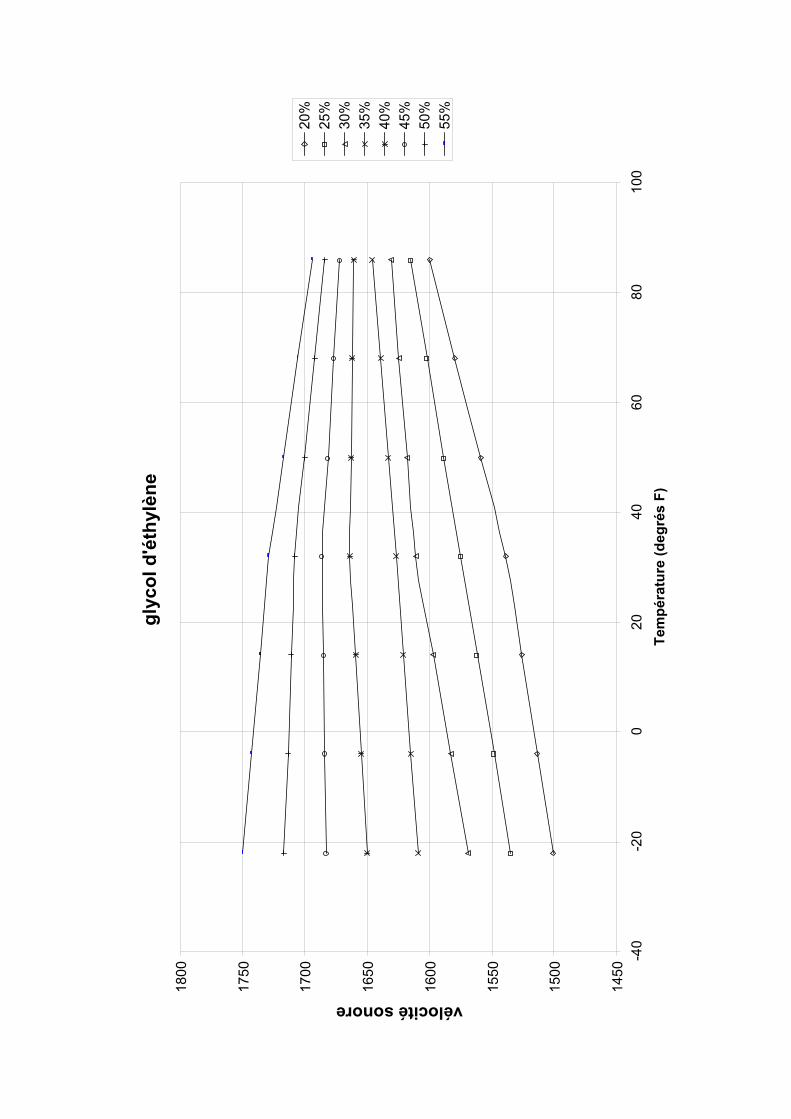
vélocité sonore
glyc
ol d
'éth
ylèn
e 18
00
1750
1700
1650
1600
1550
1500
1450
-40
55%
50%
45%
40%
35%
30%
25%
20%
-20
080
2040
6010
0Te
mpé
ratu
re (d
egré
s F)

Quick Start FUP1010 IP67 portátil ___________________
___________________
___________________
___________________
___________________
1Introducción
2Instalación
3Puesta en marcha
SITRANS F
4Solución de problemas
Caudalímetros ultrasónicos
AQuick Start FUP1010 IP67 portátil Anexo
Instrucciones de servicio
01/2013 CQO:QSG003 Revision 05

Siemens AG Industry Sector Postfach 48 48 90026 NÜRNBERG ALEMANIA
Referencia del documento: CQO:QSG003 Ⓟ 02/2013 Sujeto a cambios sin previo aviso
Copyright © Siemens AG 2013. Reservados todos los derechos
Notas jurídicas Filosofía en la señalización de advertencias y peligros
Este manual contiene las informaciones necesarias para la seguridad personal así como para la prevención de daños materiales. Las informaciones para su seguridad personal están resaltadas con un triángulo de advertencia; las informaciones para evitar únicamente daños materiales no llevan dicho triángulo. De acuerdo al grado de peligro las consignas se representan, de mayor a menor peligro, como sigue.
PELIGRO Significa que, si no se adoptan las medidas preventivas adecuadas se producirá la muerte, o bien lesiones corporales graves.
ADVERTENCIA Significa que, si no se adoptan las medidas preventivas adecuadas puede producirse la muerte o bien lesiones corporales graves.
PRECAUCIÓN Significa que si no se adoptan las medidas preventivas adecuadas, pueden producirse lesiones corporales.
ATENCIÓN Significa que si no se adoptan las medidas preventivas adecuadas, pueden producirse daños materiales.
Si se dan varios niveles de peligro se usa siempre la consigna de seguridad más estricta en cada caso. Si en una consigna de seguridad con triángulo de advertencia se alarma de posibles daños personales, la misma consigna puede contener también una advertencia sobre posibles daños materiales.
Personal cualificado El producto/sistema tratado en esta documentación sólo deberá ser manejado o manipulado por personal cualificado para la tarea encomendada y observando lo indicado en la documentación correspondiente a la misma, particularmente las consignas de seguridad y advertencias en ella incluidas. Debido a su formación y experiencia, el personal cualificado está en condiciones de reconocer riesgos resultantes del manejo o manipulación de dichos productos/sistemas y de evitar posibles peligros.
Uso previsto o de los productos de Siemens Considere lo siguiente:
ADVERTENCIA Los productos de Siemens sólo deberán usarse para los casos de aplicación previstos en el catálogo y la documentación técnica asociada. De usarse productos y componentes de terceros, éstos deberán haber sido recomendados u homologados por Siemens. El funcionamiento correcto y seguro de los productos exige que su transporte, almacenamiento, instalación, montaje, manejo y mantenimiento hayan sido realizados de forma correcta. Es preciso respetar las condiciones ambientales permitidas. También deberán seguirse las indicaciones y advertencias que figuran en la documentación asociada.
Marcas registradas Todos los nombres marcados con ® son marcas registradas de Siemens AG. Los restantes nombres y designaciones contenidos en el presente documento pueden ser marcas registradas cuya utilización por terceros para sus propios fines puede violar los derechos de sus titulares.
Exención de responsabilidad Hemos comprobado la concordancia del contenido de esta publicación con el hardware y el software descritos. Sin embargo, como es imposible excluir desviaciones, no podemos hacernos responsable de la plena concordancia. El contenido de esta publicación se revisa periódicamente; si es necesario, las posibles las correcciones se incluyen en la siguiente edición.

Índice
1 Introducción ............................................................................................................................................... 5
1.1 Introducción....................................................................................................................................5
1.2 Elementos suministrados...............................................................................................................5
2 Instalación ................................................................................................................................................. 7
2.1 Directrices de aplicación ................................................................................................................7
2.2 Formatear la batería interna ..........................................................................................................9
2.3 Conexión del adaptador de energía/cargador AC .......................................................................11
3 Puesta en marcha.................................................................................................................................... 13
3.1 Conexión de la alimentación AC..................................................................................................13
3.2 Navegación por el menú ..............................................................................................................14
3.3 Ajustar los parámetros .................................................................................................................17
3.4 Instalación del sensor ..................................................................................................................25 3.4.1 Información general .....................................................................................................................25 3.4.2 Instalar los sensores. ...................................................................................................................25 3.4.3 Ajuste final....................................................................................................................................29
4 Solución de problemas ............................................................................................................................ 31
4.1 Localización averías ....................................................................................................................31
4.2 Códigos de alarma.......................................................................................................................34
A Anexo ...................................................................................................................................................... 37
A.1 Conexiones y cableado de E/S....................................................................................................37
Tablas
Tabla 2- 1 Códigos de cables de alimentación ...............................................................................................9 Tabla 3- 1 Resumen de las funciones del teclado ........................................................................................15 Tabla 3- 2 Definiciones referentes a la lista de opciones para la configuración del tubo.............................20 Tabla 4- 1 Recomendaciones para localizar averías....................................................................................31 Tabla A- 1 Números de serie y datos de conexión .......................................................................................37 Tabla A- 2 Entrada/salida 2 canales/2 vías del cableado del bloque terminal..............................................38 Tabla A- 3 Especificaciones de rendimiento .................................................................................................39
Quick Start FUP1010 IP67 portátil Instrucciones de servicio, 01/2013, CQO:QSG003 Revision 05 3
Índice
Quick Start FUP1010 IP67 portátil 4 Instrucciones de servicio, 01/2013, CQO:QSG003 Revision 05
Figuras
Figura 2-1 Adaptador de energía/cargador de batería....................................................................................8 Figura 2-2 Adaptador de energía/cargador AC para caudalímetros de doble canal ....................................11 Figura 3-1 Adaptador de energía/cargador AC para caudalímetros monocanal y de doble canal ...............13 Figura 3-2 Teclado.........................................................................................................................................15 Figura 3-3 Pantalla típica del menú de instalación........................................................................................16 Figura 3-4 Etiqueta del sensor universal .......................................................................................................22 Figura 3-5 Etiqueta del sensor de alta precisión ...........................................................................................23 Figura 3-6 Montaje de modo "Reflejar" con marcos de montaje y espaciador (vista frontal) .......................26 Figura 3-7 Sensor ..........................................................................................................................................28 Figura 3-8 Instalación del sensor ..................................................................................................................28 Figura 3-9 Conexión de sensores al caudalímetro........................................................................................29 Figura 3-10 Ajuste final....................................................................................................................................30 Figura 3-11 Medición del caudal .....................................................................................................................30

Introducción 11.1 Introducción
l modo de
rocedimientos también se pueden aplicar a modelos
ns Si-Ware en [http://s13.me/ns/cv] para ayudarle en la instalación del caudalímetro.
es con respecto a la seguridad, consulte las instrucciones de servicio adjuntas a la unidad.
Esta Quick Start se aplica a los caudalímetros portátiles Siemens FUP1010 para intemperieIP67. Se incluyen procedimientos para formatear y cargar la batería y utilizar el adaptador de AC. Además se muestra un ajuste típico utilizando sensores de la serie D en eoperación "Reflejar" (para más información sobre el modo "Directo" consulte las instrucciones de servicio). Estos pmonocanal y multicanal.
Descargue el programa Sieme
Nota
Indicación de seguridad importante: Si desea conocer las clasificaciones y consideraciones más relevant
(para intemperie): Versión 3.02.02 y posteriores y versión 4.03.00 y posteriores.
Nota
Esta Quick Start Guide se aplica a los siguientes sistemas operativos del FUP1010 IP67
1.2 Elementos suministrados ● Transmisores SITRANS FUS1010 IP65 NEMA 4X e IP66 NEMA 7
ción del SITRANS F
● Quick Start Guide
Para más información consulte la lista de embalaje.
● CD con documenta
Nota
Quick Start FUP1010 IP67 portátil Instrucciones de servicio, 01/2013, CQO:QSG003 Revision 05 5

Introducción 1.2 Elementos suministrados
Quick Start FUP1010 IP67 portátil 6 Instrucciones de servicio, 01/2013, CQO:QSG003 Revision 05
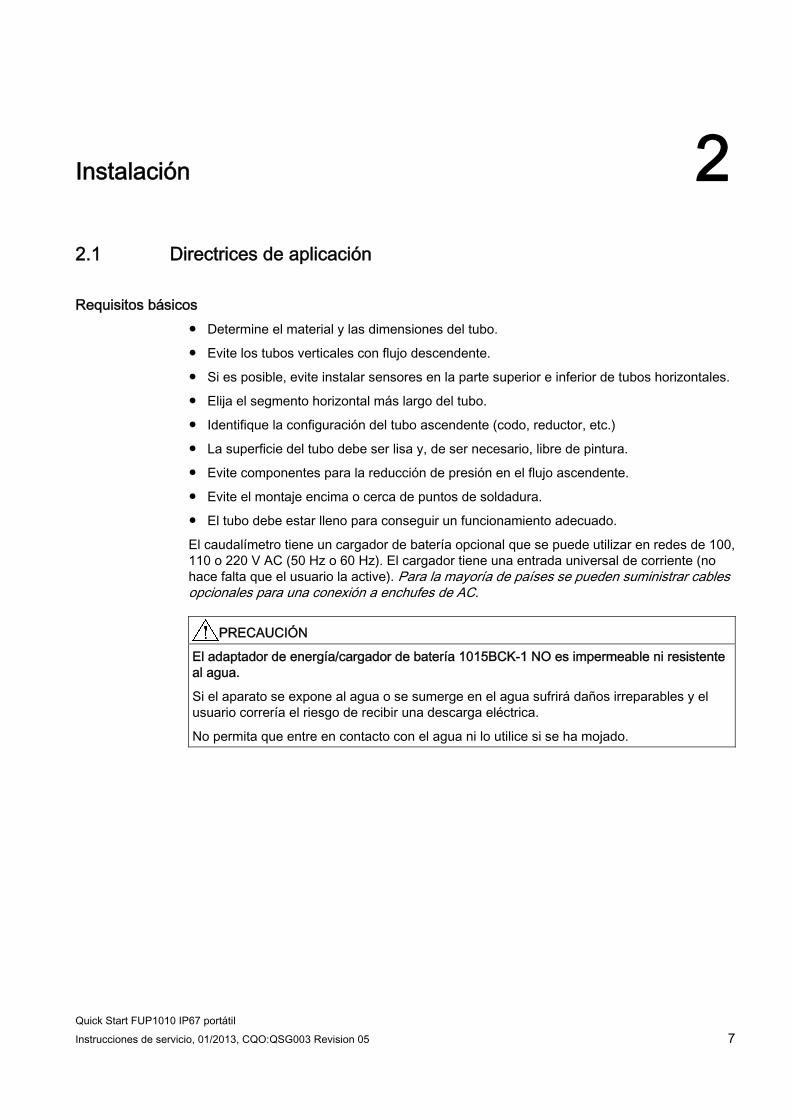
Instalación 22.1 Directrices de aplicación
Requisitos básicos ● Determine el material y las dimensiones del tubo.
● Evite los tubos verticales con flujo descendente.
● Si es posible, evite instalar sensores en la parte superior e inferior de tubos horizontales.
● Elija el segmento horizontal más largo del tubo.
● Identifique la configuración del tubo ascendente (codo, reductor, etc.)
● La superficie del tubo debe ser lisa y, de ser necesario, libre de pintura.
● Evite componentes para la reducción de presión en el flujo ascendente.
● Evite el montaje encima o cerca de puntos de soldadura.
● El tubo debe estar lleno para conseguir un funcionamiento adecuado.
El caudalímetro tiene un cargador de batería opcional que se puede utilizar en redes de 100, 110 o 220 V AC (50 Hz o 60 Hz). El cargador tiene una entrada universal de corriente (no hace falta que el usuario la active). Para la mayoría de países se pueden suministrar cables opcionales para una conexión a enchufes de AC.
PRECAUCIÓN El adaptador de energía/cargador de batería 1015BCK-1 NO es impermeable ni resistente al agua.
Si el aparato se expone al agua o se sumerge en el agua sufrirá daños irreparables y el usuario correría el riesgo de recibir una descarga eléctrica.
No permita que entre en contacto con el agua ni lo utilice si se ha mojado.
Quick Start FUP1010 IP67 portátil Instrucciones de servicio, 01/2013, CQO:QSG003 Revision 05 7

Instalación 2.1 Directrices de aplicación
Quick Start FUP1010 IP67 portátil 8 Instrucciones de servicio, 01/2013, CQO:QSG003 Revision 05
① Entrada de corriente IEC 320 ②. Conector ③ mínimo 0,9 metros (3 pies) ④ NEMA 5 - 15P (véase la tabla de cables de alimentación) ⑤ Clavija IEC 320 (véase la tabla de cables de alimentación)
Figura 2-1 Adaptador de energía/cargador de batería
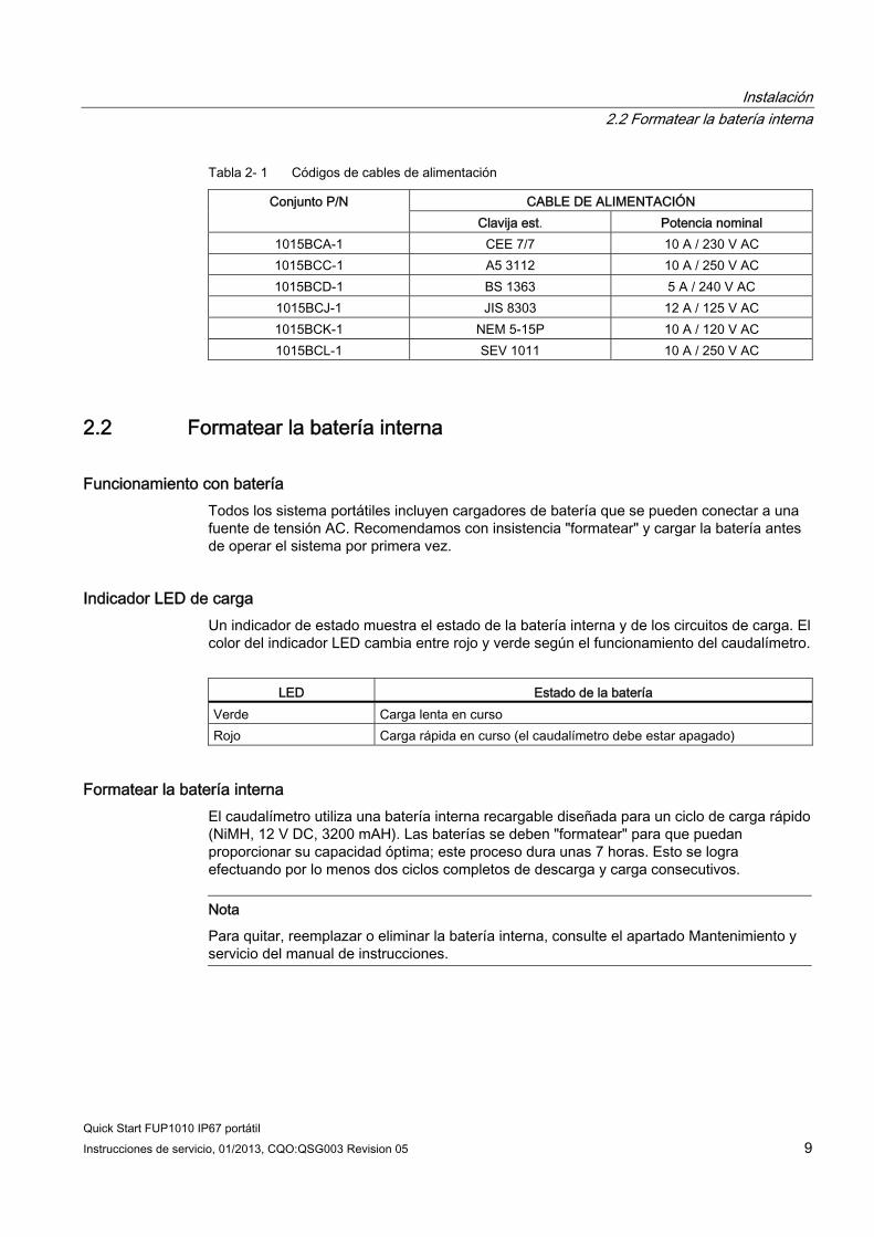
Instalación 2.2 Formatear la batería interna
Quick Start FUP1010 IP67 portátil Instrucciones de servicio, 01/2013, CQO:QSG003 Revision 05 9
Tabla 2- 1 Códigos de cables de alimentación
CABLE DE ALIMENTACIÓN Conjunto P/N Clavija est. Potencia nominal
1015BCA-1 CEE 7/7 10 A / 230 V AC 1015BCC-1 A5 3112 10 A / 250 V AC 1015BCD-1 BS 1363 5 A / 240 V AC 1015BCJ-1 JIS 8303 12 A / 125 V AC 1015BCK-1 NEM 5-15P 10 A / 120 V AC 1015BCL-1 SEV 1011 10 A / 250 V AC
2.2 Formatear la batería interna
Funcionamiento con batería Todos los sistema portátiles incluyen cargadores de batería que se pueden conectar a una fuente de tensión AC. Recomendamos con insistencia "formatear" y cargar la batería antes de operar el sistema por primera vez.
Indicador LED de carga Un indicador de estado muestra el estado de la batería interna y de los circuitos de carga. El color del indicador LED cambia entre rojo y verde según el funcionamiento del caudalímetro.
LED Estado de la batería
Verde Carga lenta en curso Rojo Carga rápida en curso (el caudalímetro debe estar apagado)
Formatear la batería interna El caudalímetro utiliza una batería interna recargable diseñada para un ciclo de carga rápido (NiMH, 12 V DC, 3200 mAH). Las baterías se deben "formatear" para que puedan proporcionar su capacidad óptima; este proceso dura unas 7 horas. Esto se logra efectuando por lo menos dos ciclos completos de descarga y carga consecutivos.
Nota
Para quitar, reemplazar o eliminar la batería interna, consulte el apartado Mantenimiento y servicio del manual de instrucciones.

Instalación 2.2 Formatear la batería interna
Quick Start FUP1010 IP67 portátil 10 Instrucciones de servicio, 01/2013, CQO:QSG003 Revision 05
Para efectuar un ciclo de carga y descarga:
1. Pulse la tecla ON para ENCENDER el caudalímetro sin conectar una fuente externa de tensión. Deje el caudalímetro en ON hasta que se apague automáticamente.
2. Conecte el cargador AC (Página 11) y cargue la batería interna con el caudalímetro apagado. El indicador LED de carga se pondrá ROJO (carga rápida) durante 1 o 2 horas y después pasará a color VERDE (carga lenta). Cargue la batería durante 8 horas más, como mínimo.
3. Repita el ciclo de carga y descarga. Después de esto la batería debe quedar "formateada" para proporcionar su capacidad máxima.
Para mantener la batería "formateada", siempre que sea posible descárguela completamente antes de recargarla. Si al utilizar la batería el tiempo de funcionamiento parece ser más corto de lo normal, un ciclo de descarga/carga debería alargar el tiempo de funcionamiento. Si esta medida no corrige un tiempo de funcionamiento corto, se debe reemplazar la batería interna.
Estado Indicación Acción
Alarma sonora de la batería Funcionamiento normal, alarma sonora periódica
Conecte un cargador de batería para un funcionamiento continuo.
Descarga de la batería La unidad no se encenderá (no aparece la pantalla de visualización)
Conecte el cargador de batería por lo menos 1,5 horas antes de encender la unidad.
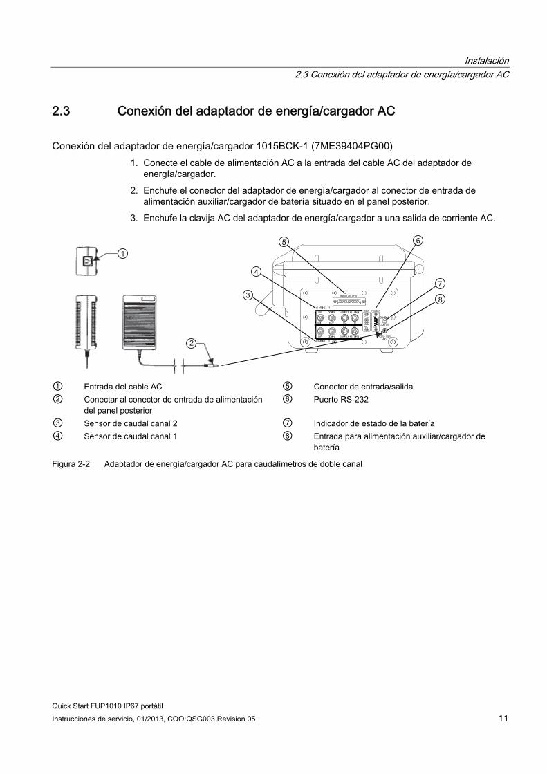
Instalación 2.3 Conexión del adaptador de energía/cargador AC
Quick Start FUP1010 IP67 portátil Instrucciones de servicio, 01/2013, CQO:QSG003 Revision 05 11
2.3 Conexión del adaptador de energía/cargador AC
Conexión del adaptador de energía/cargador 1015BCK-1 (7ME39404PG00) 1. Conecte el cable de alimentación AC a la entrada del cable AC del adaptador de
energía/cargador.
2. Enchufe el conector del adaptador de energía/cargador al conector de entrada de alimentación auxiliar/cargador de batería situado en el panel posterior.
3. Enchufe la clavija AC del adaptador de energía/cargador a una salida de corriente AC.
① Entrada del cable AC ⑤ Conector de entrada/salida ② Conectar al conector de entrada de alimentación
del panel posterior ⑥ Puerto RS-232
③ Sensor de caudal canal 2 ⑦ Indicador de estado de la batería ④ Sensor de caudal canal 1 ⑧ Entrada para alimentación auxiliar/cargador de
batería
Figura 2-2 Adaptador de energía/cargador AC para caudalímetros de doble canal

Instalación 2.3 Conexión del adaptador de energía/cargador AC
Quick Start FUP1010 IP67 portátil 12 Instrucciones de servicio, 01/2013, CQO:QSG003 Revision 05

3Puesta en marcha
3.1 Conexión de la alimentación AC
Conexión del adaptador de energía/cargador 1015BCK-1 (7ME39404PG00) 1. Conecte el cable de alimentación AC a la entrada del cable AC del adaptador de
energía/cargador.
2. Enchufe el conector del adaptador de energía al conector posterior de entrada de alimentación del panel.
① Entrada del cable AC ② Conectar al conector de entrada de alimentación del panel posterior ③ Indicador de estado de la batería ④ Entrada para alimentación auxiliar/cargador de batería
Figura 3-1 Adaptador de energía/cargador AC para caudalímetros monocanal y de doble canal
Quick Start FUP1010 IP67 portátil Instrucciones de servicio, 01/2013, CQO:QSG003 Revision 05 13
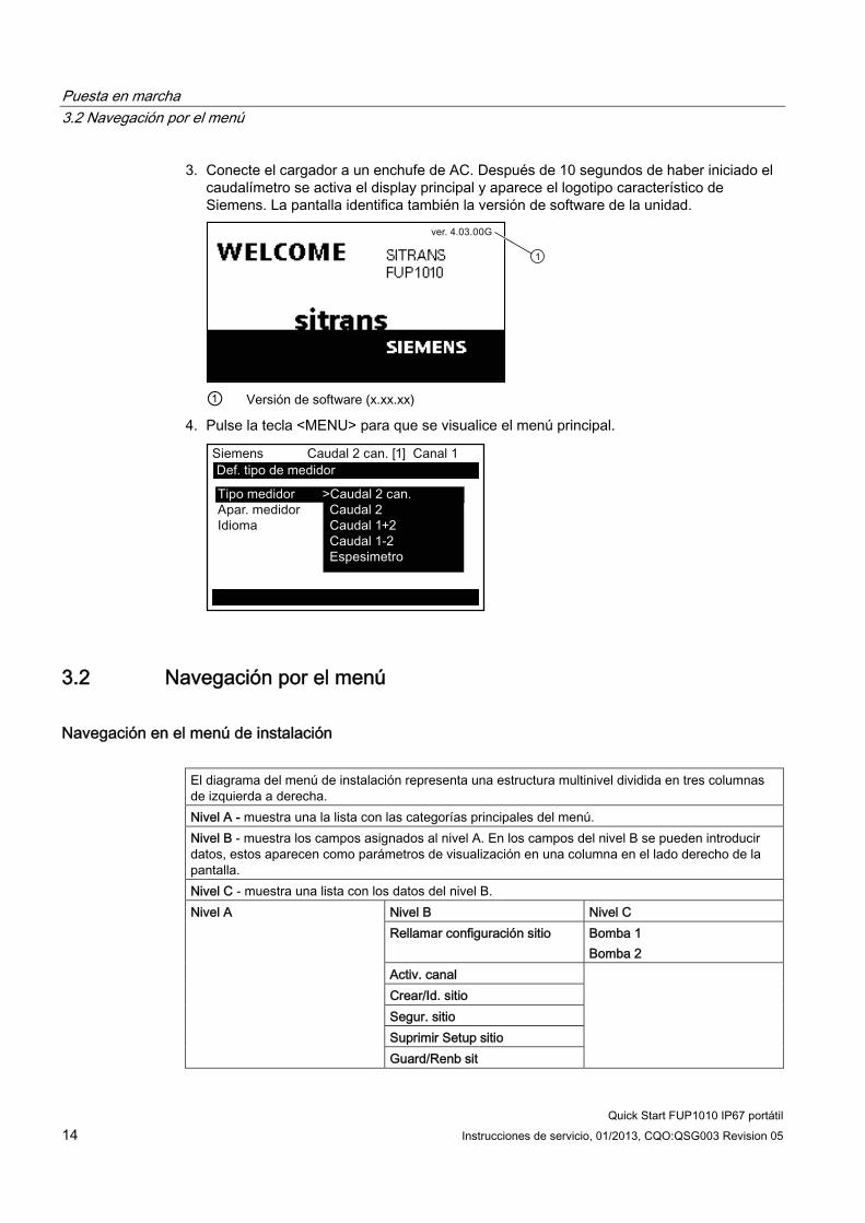
Puesta en marcha 3.2 Navegación por el menú
Quick Start FUP1010 IP67 portátil 14 Instrucciones de servicio, 01/2013, CQO:QSG003 Revision 05
3. Conecte el cargador a un enchufe de AC. Después de 10 segundos de haber iniciado el caudalímetro se activa el display principal y aparece el logotipo característico de Siemens. La pantalla identifica también la versión de software de la unidad.
① Versión de software (x.xx.xx)
4. Pulse la tecla <MENU> para que se visualice el menú principal.
3.2 Navegación por el menú
Navegación en el menú de instalación El diagrama del menú de instalación representa una estructura multinivel dividida en tres columnas de izquierda a derecha. Nivel A - muestra una la lista con las categorías principales del menú. Nivel B - muestra los campos asignados al nivel A. En los campos del nivel B se pueden introducir datos, estos aparecen como parámetros de visualización en una columna en el lado derecho de la pantalla. Nivel C - muestra una lista con los datos del nivel B.
Nivel B Nivel C Rellamar configuración sitio Bomba 1
Bomba 2
Nivel A
Activ. canal Crear/Id. sitio Segur. sitio Suprimir Setup sitio Guard/Renb sit

Puesta en marcha 3.2 Navegación por el menú
Quick Start FUP1010 IP67 portátil Instrucciones de servicio, 01/2013, CQO:QSG003 Revision 05 15
+-= +
*
F1 F3F2 F4
MENU CLR ENTER
DATALOG
ALTCTRL
HELP
1 2 30
7 8 94 5 6
Figura 3-2 Teclado
Nota
La tecla <Flecha izquierda> permite regresar al menú anterior.
Tabla 3- 1 Resumen de las funciones del teclado
Teclas Descripción MENU Activa el menú de instalación. ENTER Para guardar datos numéricos, seleccionar dentro de listas de opciones, etc. Flechas izquierda / derecha Teclas para navegar por el menú, mueven el cursor en la dirección correspondiente. Flechas arriba / abajo Como las flechas <izquierda> y <derecha>. Para desplazarse dentro de listas de
opciones e indicaciones gráficas. CLR Para borrar datos o seleccionar opciones de una lista. Números 0 - 9 Para introducir datos numéricos. Carácter decimal Para introducir el punto decimal en datos numéricos. Signos matemáticos Para realizar las cuatro funciones matemáticas en campos de entrada numéricos. Teclas de funciones F1-F3 Para iniciar/parar/inicializar el totalizador. F4 Atención: para resetear el sistema durante el arranque. CTRL y ALT Se utilizan para conmutar las funciones de las teclas y activar funciones alternativas. DATALOG Dispara el registrador inmediato de datos. Más y menos [+ / -] Cambia los signos de los datos numéricos.

Puesta en marcha 3.2 Navegación por el menú
Quick Start FUP1010 IP67 portátil 16 Instrucciones de servicio, 01/2013, CQO:QSG003 Revision 05
① Datos del campo (columna izquierda) ⑤ Canal de medición seleccionado actualmente ② Campo seleccionado ⑥ Nombre del sitio identificado ③ Línea indicadora del menú
(representación invertida) ⑦ Datos seleccionados
④ Caudalímetro seleccionado actualmente
⑧ Datos del campo (columna derecha)
Figura 3-3 Pantalla típica del menú de instalación
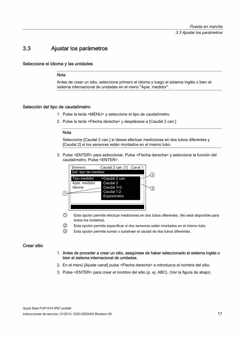
Puesta en marcha 3.3 Ajustar los parámetros
Quick Start FUP1010 IP67 portátil Instrucciones de servicio, 01/2013, CQO:QSG003 Revision 05 17
3.3 Ajustar los parámetros
Seleccione el idioma y las unidades
Nota
Antes de crear un sitio, seleccione primero el idioma y luego el sistema inglés o bien el sistema internacional de unidades en el menú "Apar. medidor".
Selección del tipo de caudalímetro 1. Pulse la tecla <MENU> y seleccione el tipo de caudalímetro.
2. Pulse la tecla <Flecha derecha> y desplácese a [Caudal 2 can.]
Nota
Seleccione [Caudal 2 can.] si desea efectuar mediciones en dos tubos diferentes y [Caudal 2] si los sensores están montados en el mismo tubo.
3. Pulse <ENTER> para seleccionar. Pulse <Flecha derecha> y seleccione la función del caudalímetro. Pulse <ENTER>.
① Esta opción permite efectuar mediciones en dos tubos diferentes. (No está disponible para
todos los modelos). ② Esta opción permite especificar si dos sensores están montados en el mismo tubo. ③ Esta opción permite sumar o substraer el caudal de dos tubos diferentes.
Crear sitio 1. Antes de proceder a crear un sitio, asegúrese de haber seleccionado el sistema inglés o
bien el sistema internacional de unidades.
2. En el menú [Ajuste canal] pulse <Flecha derecha> e introduzca el nombre del sitio.
3. Pulse <ENTER> para crear el nombre del sitio (p. ej. ABC). (Ver la figura de abajo).

Puesta en marcha 3.3 Ajustar los parámetros
Quick Start FUP1010 IP67 portátil 18 Instrucciones de servicio, 01/2013, CQO:QSG003 Revision 05
Nota
Para ajustar el sistema inglés o bien el sistema internacional de unidades: Dentro del menú "Tipo medidor", desplácese al menú "Apar. medidor". Pulse <Flecha derecha> y seleccione el sistema deseado. Pulse <ENTER> para seleccionar. Pulse <Flecha izquierda> y <Flecha arriba> para regresar al menú "Tipo medidor".
Nota
Para seleccionar letras: Pulse <Flecha derecha> para mover el cursor y luego pulse <Flechas arriba/abajo> para seleccionar letras y números. Pulse <ENTER> una vez haya finalizado la selección.
① Introduzca el nombre deseado (máx. 8 caracteres)
4. Desplácese a [Guard/Renb sit]. Pulse <Flecha derecha> y luego <ENTER> para guardar el sitio.
5. Pulse <Flecha izquierda> y regrese al menú principal.
Selección de la clase de tubo 1. Pulse <Flecha derecha> para seleccionar la clase de tubo. Pulse <Flecha derecha> otra
vez y desplácese a la clase de tubo deseada.
2. Pulse <ENTER> para seleccionar.
3. En los campos aparecen dimensiones y parámetros importantes predefinidos para los
tubos. Pulse <Flecha derecha> y desplácese a la dimensión de tubo deseada.
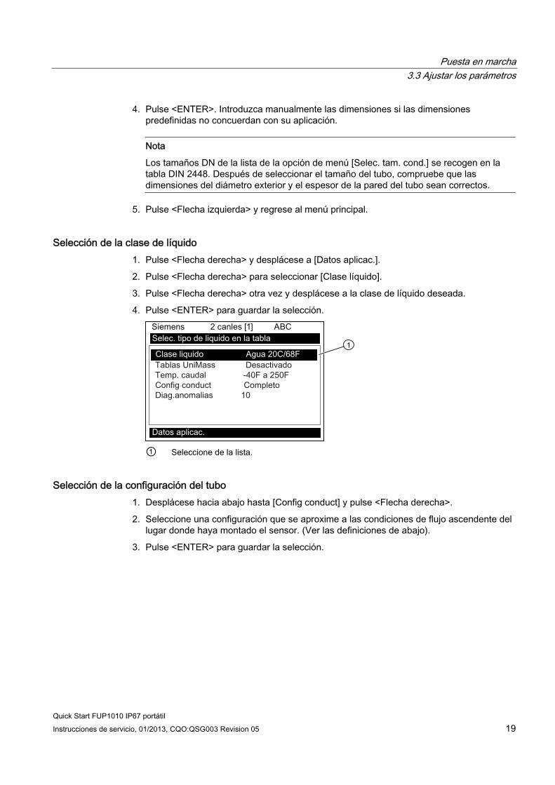
Puesta en marcha 3.3 Ajustar los parámetros
Quick Start FUP1010 IP67 portátil Instrucciones de servicio, 01/2013, CQO:QSG003 Revision 05 19
4. Pulse <ENTER>. Introduzca manualmente las dimensiones si las dimensiones predefinidas no concuerdan con su aplicación.
Nota
Los tamaños DN de la lista de la opción de menú [Selec. tam. cond.] se recogen en la tabla DIN 2448. Después de seleccionar el tamaño del tubo, compruebe que las dimensiones del diámetro exterior y el espesor de la pared del tubo sean correctos.
5. Pulse <Flecha izquierda> y regrese al menú principal.
Selección de la clase de líquido 1. Pulse <Flecha derecha> y desplácese a [Datos aplicac.].
2. Pulse <Flecha derecha> para seleccionar [Clase líquido].
3. Pulse <Flecha derecha> otra vez y desplácese a la clase de líquido deseada.
4. Pulse <ENTER> para guardar la selección.
① Seleccione de la lista.
Selección de la configuración del tubo 1. Desplácese hacia abajo hasta [Config conduct] y pulse <Flecha derecha>.
2. Seleccione una configuración que se aproxime a las condiciones de flujo ascendente del lugar donde haya montado el sensor. (Ver las definiciones de abajo).
3. Pulse <ENTER> para guardar la selección.

Puesta en marcha 3.3 Ajustar los parámetros
Quick Start FUP1010 IP67 portátil 20 Instrucciones de servicio, 01/2013, CQO:QSG003 Revision 05
① Utilice este campo para introducir el número de diámetros de tubo entre la configuración de
flujo ascendente y la instalación del sensor. ② Utilice este campo para seleccionar la configuración de tubo que más se ajuste a las
condiciones de flujo ascendente del tubo.
4. Pulse <Flecha izquierda> y regrese al menú principal.
Tabla 3- 2 Definiciones referentes a la lista de opciones para la configuración del tubo
Opciones Definiciones Completo Caudal pleno, así suelen ser las condiciones de caudal en
segmentos muy largos de tubos horizontales o en instalaciones de flujo descendente.
1 Codo Codo individual de 90 grados situado contracorriente del lugar de instalación del sensor.
Codo doble+ Codo doble en dos niveles situado contracorriente del lugar de instalación del sensor.
Codo doble- Codo doble en un nivel situado contracorriente del lugar de instalación del sensor.
Válvula Actualmente no está disponible. Expansor Expansor del tubo situado contracorriente del lugar de
instalación del sensor. Reductor Reductor del tubo situado contracorriente del lugar de
instalación del sensor. Entrada norm Actualmente no está disponible. Entr. colector Colector o tubo distribuidor situado contracorriente del lugar
de instalación del sensor. Entradas Actualmente no está disponible.
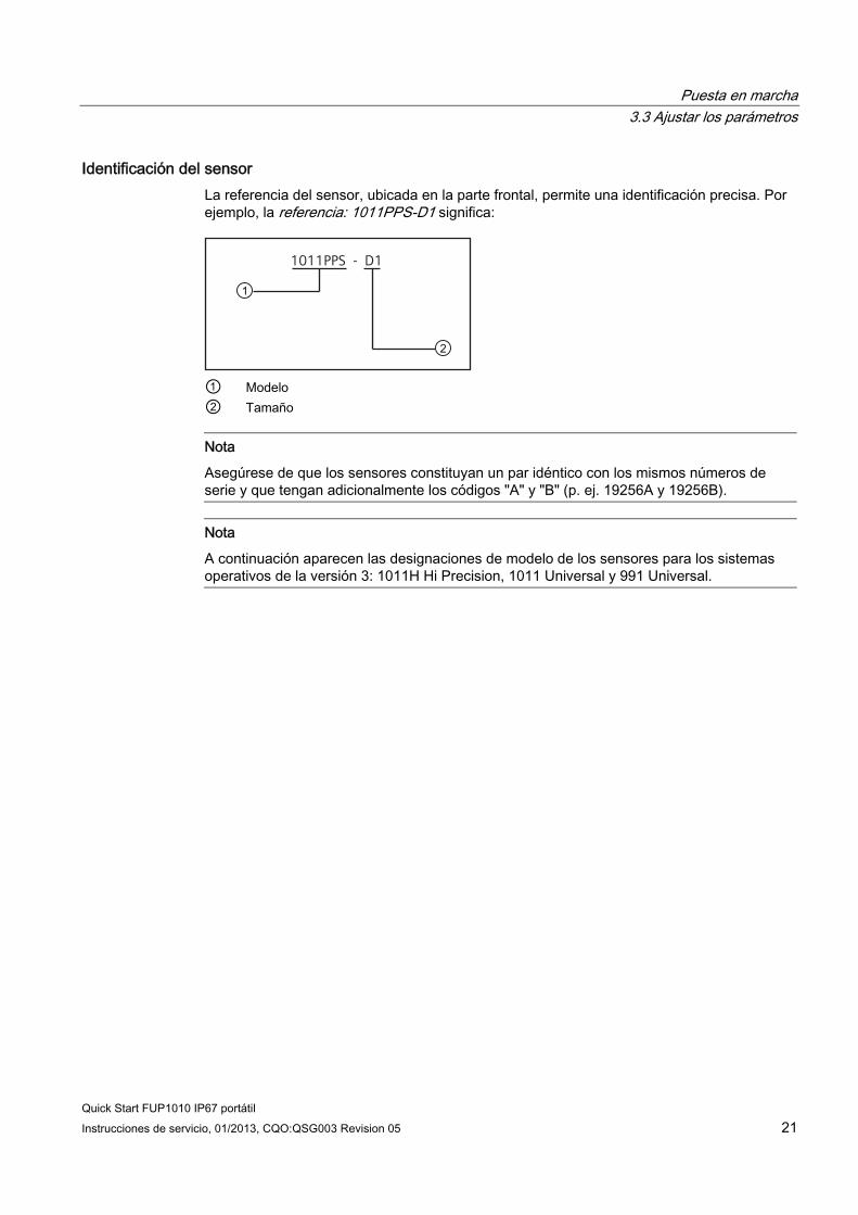
Puesta en marcha 3.3 Ajustar los parámetros
Quick Start FUP1010 IP67 portátil Instrucciones de servicio, 01/2013, CQO:QSG003 Revision 05 21
Identificación del sensor La referencia del sensor, ubicada en la parte frontal, permite una identificación precisa. Por ejemplo, la referencia: 1011PPS-D1 significa:
1011PPS - D1
① Modelo ② Tamaño
Nota
Asegúrese de que los sensores constituyan un par idéntico con los mismos números de serie y que tengan adicionalmente los códigos "A" y "B" (p. ej. 19256A y 19256B).
Nota
A continuación aparecen las designaciones de modelo de los sensores para los sistemas operativos de la versión 3: 1011H Hi Precision, 1011 Universal y 991 Universal.

Puesta en marcha 3.3 Ajustar los parámetros
Quick Start FUP1010 IP67 portátil 22 Instrucciones de servicio, 01/2013, CQO:QSG003 Revision 05
Etiquetas típicas del sensor
① Número de modelo del sensor universal ② Tamaño del sensor
Figura 3-4 Etiqueta del sensor universal
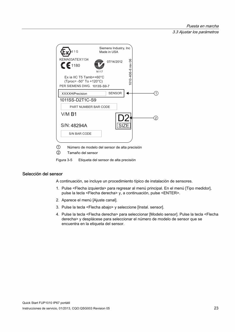
Puesta en marcha 3.3 Ajustar los parámetros
Quick Start FUP1010 IP67 portátil Instrucciones de servicio, 01/2013, CQO:QSG003 Revision 05 23
① Número de modelo del sensor de alta precisión ② Tamaño del sensor
Figura 3-5 Etiqueta del sensor de alta precisión
Selección del sensor A continuación, se incluye un procedimiento típico de instalación de sensores.
1. Pulse <Flecha izquierda> para regresar al menú principal. En el menú [Tipo medidor], pulse la tecla <Flecha derecha> y, a continuación, pulse <ENTER>.
2. Aparece el menú [Ajuste canal].
3. Pulse la tecla <Flecha abajo> y seleccione [Instal. sensor].
4. Pulse la tecla <Flecha derecha> para seleccionar [Modelo sensor]. Pulse la tecla <Flecha derecha> y desplácese para seleccionar el número de modelo de sensor que se encuentra en la etiqueta del sensor.

Puesta en marcha 3.3 Ajustar los parámetros
Quick Start FUP1010 IP67 portátil 24 Instrucciones de servicio, 01/2013, CQO:QSG003 Revision 05
5. El menú desplegable ofrece una lista con las siguientes selecciones de sensores:
– 1011 universal
– 1011HP-T1 - Utilizable entre -40 °C y 120 °C, recomendado para temperatura Ø < 40 °C; estándar.
– 1011HP-T2 - Utilizable entre -40 °C y 120 °C, recomendado para temperaturas Ø > 40 °C - < 80 °C; conocido como alta temperatura.
– 1011HP-T3 - Utilizable entre -40 °C y 120 °C, recomendado para temperaturas Ø > 80 °C - < 120 °C; solicitud especial.
– 991 universal
Nota
El medidor recomendará automáticamente un sensor según los datos de aplicación que se hayan introducido.
6. Para este ejemplo, seleccione el modelo de sensor que figura en la etiqueta del sensor y, a continuación, pulse <ENTER>.
① Seleccione aquí el tipo. ② Seleccione aquí el tamaño. ③ Una vez montado el sensor, seleccione [Instalación].
7. Para seleccionar el tamaño del sensor pulse la tecla <Flecha derecha>. Desplácese para seleccionar el tamaño del sensor que coincida con el tamaño indicado en la etiqueta del sensor. Pulse <ENTER>.
8. En [Montaje sensor], pulse la tecla <Flecha derecha>. Desplácese para seleccionar el montaje [Reflejar] o [Directo] y, después, pulse <ENTER>.
9. IMPORTANTE: Anote el método de separación y el índice del número. Estos datos se utilizarán en el montaje de los sensores.
10. Ahora se pueden montar los sensores. Consulte los procedimientos de montaje Instalación del sensor (Página 25) y seleccione el modo de montaje que desee.
11. Una vez montados los sensores, desplácese a la opción [Instalación OK] y seleccione [Instalación].

Puesta en marcha 3.4 Instalación del sensor
Quick Start FUP1010 IP67 portátil Instrucciones de servicio, 01/2013, CQO:QSG003 Revision 05 25
3.4 Instalación del sensor
3.4.1 Información general
Modos de montaje "Reflejar" y "Directo" Se soportan los modos de montaje "Reflejar" y "Directo" para sensores clamp-on. El transmisor recomienda un modo de montaje después de analizar los datos entrados relacionados con el tubo y el líquido en cuestión. Esta Quick Start muestra el ajuste típico de un sensor utilizando el modo "Reflejar".
Nota
Para más información sobre el montaje "Directo", consulte el manual de instrucciones.
Accesorios de montaje Los siguientes elementos se requieren para montar el sensor (la mayoría vienen incluidos):
● Destornillador de paleta
● Marcos o rieles de montaje
● Cinta adhesiva, tiza y una regla o cinta métrica
● Abrazaderas
● Espaciador
● Guía de montaje (para montaje "Directo")
● Pasta adherente ultrasónica
● Sensores (par correspondiente)
3.4.2 Instalar los sensores.
Instalación del modo "Reflejar" utilizando marcos de montaje y espaciador 1. Una vez recibido el índice de separación del menú de instalación, prepare el área de la
superficie del tubo en la que se montarán los sensores.
2. Desengrase la superficie y retire polvo, corrosión, herrumbre y pintura desconchada, etc.
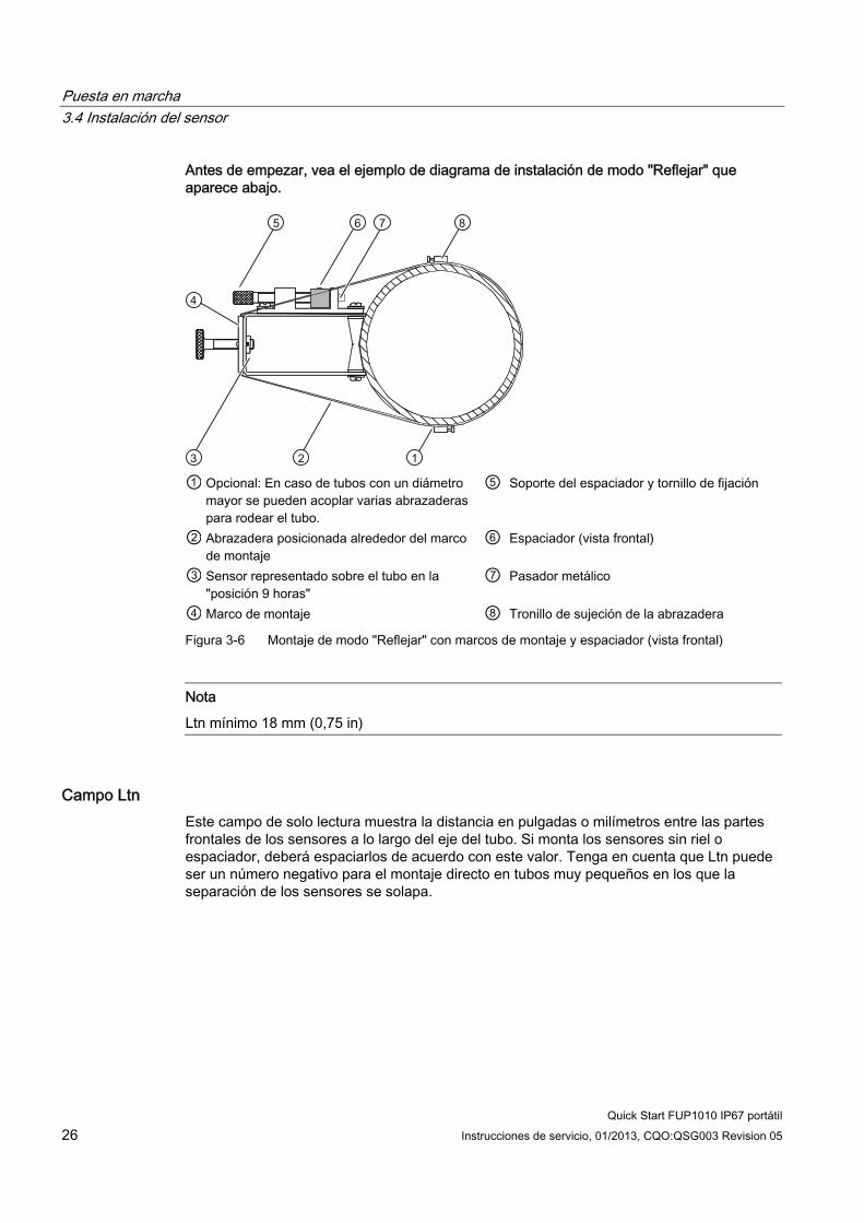
Puesta en marcha 3.4 Instalación del sensor
Quick Start FUP1010 IP67 portátil 26 Instrucciones de servicio, 01/2013, CQO:QSG003 Revision 05
Antes de empezar, vea el ejemplo de diagrama de instalación de modo "Reflejar" que aparece abajo.
① Opcional: En caso de tubos con un diámetro
mayor se pueden acoplar varias abrazaderas para rodear el tubo.
⑤ Soporte del espaciador y tornillo de fijación
② Abrazadera posicionada alrededor del marco de montaje
⑥ Espaciador (vista frontal)
③ Sensor representado sobre el tubo en la "posición 9 horas"
⑦ Pasador metálico
④ Marco de montaje ⑧ Tronillo de sujeción de la abrazadera
Figura 3-6 Montaje de modo "Reflejar" con marcos de montaje y espaciador (vista frontal)
Nota
Ltn mínimo 18 mm (0,75 in)
Campo Ltn Este campo de solo lectura muestra la distancia en pulgadas o milímetros entre las partes frontales de los sensores a lo largo del eje del tubo. Si monta los sensores sin riel o espaciador, deberá espaciarlos de acuerdo con este valor. Tenga en cuenta que Ltn puede ser un número negativo para el montaje directo en tubos muy pequeños en los que la separación de los sensores se solapa.
Puesta en marcha 3.4 Instalación del sensor
Quick Start FUP1010 IP67 portátil Instrucciones de servicio, 01/2013, CQO:QSG003 Revision 05 27
Procedimiento de instalación (ver figura correspondiente) 1. Sobre una superficie plana fije el espaciador al marco de montaje, de tal manera que el
orificio de referencia en el espaciador coincida con con el pasador metálico ubicado en el soporte del marco. Apriete el tornillo de fijación.
2. Deslice el segundo marco de montaje sobre el otro extremo del espaciador y alinee el orificio del índice de número con el pasador de metal del soporte. Luego apriete el tornillo de fijación. Asegúrese de que las caras inclinadas de ambos marcos miren hacia el exterior.
3. Ponga una abrazadera alrededor del tubo. Asegúrese de posicionar la abrazadera de tal manera que haya un libre acceso al tornillo de sujeción.
4. En el lugar de instalación, posicione el marco de montaje junto con el espaciador de tal manera que descansen en la parte superior del tubo.
5. Pase el extremo de la abrazadera por debajo del tornillo de sujeción de la misma.
6. Deslice la abrazadera por debajo del resorte de fijación de uno de los marcos de montaje.
7. Apriete el tornillo de sujeción de la abrazadera de tal manera que la misma quede tensa pero que la construcción aún se pueda manipular libremente. Repita el procedimiento con el otro marco de montaje.
8. Gire la construcción sobre el tubo hasta alcanzar la posición final asegurándose de que la misma repose correctamente sobre el eje vertical del tubo. (consulte el esquema de orientación del sensor)
9. Apriete las abrazaderas para fijar firmemente la construcción sobre el tubo. No apriete demasiado las abrazaderas.

Puesta en marcha 3.4 Instalación del sensor
Quick Start FUP1010 IP67 portátil 28 Instrucciones de servicio, 01/2013, CQO:QSG003 Revision 05
10. Aplique una capa de 3 mm (1/8 pulgada) de pasta adherente a lo largo del centro de la superficie emisora de cada sensor.
① Conector F ④ Parte frontal ② Lado inclinado ⑤ Superficie de contacto ③ Sensor ⑥ Pasta adherente Figura 3-7 Sensor
① ⑥ Vista frontal Abrazadera ② Resorte de fijación (no está presente
en todos los modelos) ⑦ Nota: La figura muestra una abrazadera
adicional. Los tubos de más de 76 cm (30 in) pueden requerir un soporte adicional.
③ Tornillo de fijación del sensor ⑧ Soporte del espaciador y tornillo de fijación ④ Espaciador ⑨ Orificio de referencia del espaciador ⑤ Bastidor de la serie 1012 ⑩ Orientación del sensor de un solo haz en la
"posición 9 horas" ⑪ Orientación del sensor de dos haces en las
posiciones "10 horas" y "2 horas" Figura 3-8 Instalación del sensor
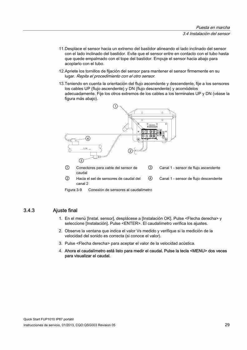
Puesta en marcha 3.4 Instalación del sensor
Quick Start FUP1010 IP67 portátil Instrucciones de servicio, 01/2013, CQO:QSG003 Revision 05 29
11. Desplace el sensor hacia un extremo del bastidor alineando el lado inclinado del sensor con el lado inclinado del bastidor. Evite que el sensor entre en contacto con el tubo hasta que quede empalmado con el tope del bastidor. Empuje el sensor hacia abajo para acoplarlo con el tubo.
12. Apriete los tornillos de fijación del sensor para mantener el sensor firmemente en su lugar. Repita el procedimiento con el otro sensor.
13. Teniendo en cuenta la orientación del flujo ascendente y descendente, fije a los sensores los cables UP (flujo ascendente) y DN (flujo descendente) y acomódelos adecuadamente. Fije los otros extremos de los cables a los terminales UP y DN (véase la figura más abajo).
① Conectores para cable del sensor de
caudal ③ Canal 1 - sensor de flujo ascendente
② Hacia el set de sensores de caudal del canal 2
④ Canal 1 - sensor de flujo descendente
Figura 3-9 Conexión de sensores al caudalímetro
3.4.3 Ajuste final 1. En el menú [Instal. sensor], desplácese a [Instalación OK]. Pulse <Flecha derecha> y
seleccione [Instalación]. Pulse <ENTER>. El caudalímetro verifica los ajustes.
2. Observe la ventana que indica el valor Vs medido y verifique si la medición de la velocidad del sonido es correcta (si conoce el valor).
3. Pulse <Flecha derecha> para aceptar el valor de la velocidad acústica.
4. Ahora el caudalímetro está listo para medir el caudal. Pulse la tecla <MENU> dos veces para visualizar el caudal.
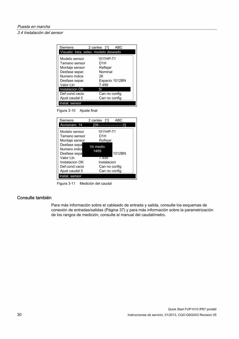
Puesta en marcha 3.4 Instalación del sensor
Quick Start FUP1010 IP67 portátil 30 Instrucciones de servicio, 01/2013, CQO:QSG003 Revision 05
Figura 3-10 Ajuste final
Figura 3-11 Medición del caudal
Consulte también Para más información sobre el cableado de entrada y salida, consulte los esquemas de conexión de entradas/salidas (Página 37) y para más información sobre la parametrización de los rangos de medición, consulte el manual del caudalímetro.

4Solución de problemas
4.1 Localización averías La siguiente lista contiene avisos y recomendaciones para localizar averías que pueden llegar a aparecer. La misma incluye explicaciones y, en algunos casos, la acción a realizar. Si un problema parece no tener solución, póngase en contacto con su oficina local de Siemens o con el representante regional del área de medición ultrasónica de caudal y solicite asistencia técnica especializada en: http://www.automation.siemens.com/partner (http://www.automation.siemens.com/partner).
Tabla 4- 1 Recomendaciones para localizar averías
Error o mensaje Causa probable Solución ¡Memoria llena! Aparece ante un intento de guardar datos
de un sitio estando llena la memoria. Borre un sitio que ya no sea relevante o abra campo en la memoria del registrador de datos para poder guardar los nuevos datos.
¡Mem. corrompida! Error de lectura de la memoria al acceder a los datos del sitio activo.
Consulte el procedimiento de reset mediante F4 en el manual de instrucciones de servicio.
Can no config Aparece ante un intento de ejecutar una operación que requiere la habilitación de un canal.
Active el canal [Ajustes Canal - Activ. canal - Sí]. Tenga en cuenta que no se podrá habilitar ningún canal hasta que no se haya realizado una operación de instalación.
¿Borrar memoria activa?
Aparece cuando se mantiene pulsada la tecla F4 durante el encendido.
Utilice la función de la tecla F4 para restablecer el funcionamiento del sistema tras un fallo grave (p. ej. si ocurre una sobretensión transitoria).
¿Borrar datos guardados?
[¿Borrar datos guardados?] solo aparece después de pulsar la tecla <Flecha abajo> en respuesta a [¿Borrar memoria activa?].
Si responde Sí a [¿Borrar datos guardados?] se borran TODOS los datos guardados. Para activar en el modo serie RS-232, escriba @@@ y, a continuación, pulse <ENTER>.
<EOT> Aparece si se solicita una salida de datos del registrador a través de la impresora o de la pantalla gráfica sin que los datos existan realmente o al final de un archivo transmitido.
Parametrice el registrador de datos.
Ningún sitio. Pulsar <ENTER>
Aparece ante un intento de llamar/borrar el setup de un sitio sin que haya sitios guardados.
Cree un sitio.
Seguridad Aparece al cambiar datos previamente introducidos cuando el conmutador de seguridad está en la posición [Desactivado] o se ha introducido un código de seguridad.
Cambie la posición del conmutador a [Activado].
Introduzca el código de seguridad previamente establecido.
Error RTC Problema de nivel componente. El caudalímetro requiere mantenimiento. Solicite una autorización de devolución de mercancía.
Quick Start FUP1010 IP67 portátil Instrucciones de servicio, 01/2013, CQO:QSG003 Revision 05 31

Solución de problemas 4.1 Localización averías
Quick Start FUP1010 IP67 portátil 32 Instrucciones de servicio, 01/2013, CQO:QSG003 Revision 05
Error o mensaje Causa probable Solución - - -F- - - Alarma fallo Pérdida de intensidad de la señal (ALC)
Cambio de ubicación de la señal Rx (soplado de haz)
Vuelva a acoplar los sensores con adhesivo nuevo.
Instale los sensores en modo de montaje Directo
Nota: si el problema persiste, llame al servicio de asistencia técnica.
Modificar índice de espaciamiento
La velocidad sónica de fluidos medida (Vs) es superior al +/-25 % del rango Vs medio.
Asegúrese de que las dimensiones de los tubos o las entradas de datos de fluido sean correctas.
Indique debidamente el tamaño del sensor correcto en el menú [Instal. sensor] del caudalímetro.
Confirme que la separación del sensor sea correcta comprobando los parámetros de separación del menú [Instal. sensor].
Ajuste no válido (utilice el modo "Directo")
Durante el arranque inicial, el sistema detecta una separación de sensores no válida, parámetros de fluido/tubo no válidos o cualquier otro factor que impida finalizar el arranque inicial.
Esto puede ocurrir por uno de los siguientes motivos: Una entrada de datos fuera de rango. Una condición no válida (p. ej. funcionamiento
simultáneo de los sensores en el modo "Reflejar"). Si no se logra resolver el problema seleccionando el modo "Directo", verifique toda la configuración del sitio y las opciones de instalación de los sensores, en particular los datos introducidos referentes al tubo y al fluido.
En el modo "Reflejar", el caudalímetro detecta que la señal de la pared del tubo posiblemente afecte a la señal del fluido. Seleccione el modo "Directo".
Pulse <ENTER>, <Flecha arriba>, <Flecha abajo> o <Flecha izquierda> para cancelar la rutina de instalación. Puede seguir programando otro sitio, el problema posiblemente se pueda resolver más adelante. Si es necesario, póngase en contacto con la asistencia técnica.

Solución de problemas 4.1 Localización averías
Quick Start FUP1010 IP67 portátil Instrucciones de servicio, 01/2013, CQO:QSG003 Revision 05 33
Error o mensaje Causa probable Solución Señal baja. Pulsar <ENTER>
Durante el arranque inicial, el caudalímetro detecta que el nivel de la señal recibida es insuficiente para garantizar un funcionamiento correcto.
Las razones para una señal débil pueden ser: Activación de [Instalación efectuada?] con el
tubo vacío. La pasta adhesiva es insuficiente, no ha sido
aplicada o se ha evaporado. Volver a aplicar adhesivo.
Un cable del sensor se ha soltado o presenta fallos.
El tubo debe ser reacondicionado en la posición de montaje.
Burbujas grandes afectan la recepción de señales, se requiere una limpieza.
Los cables del sensor presentan fallos o no están conectados al canal correcto.
La rutina de parametrización en vacío se realizó y el tubo NO estaba realmente vacío.
Si detecta y corrige inmediatamente el fallo, pulse <ENTER> para continuar con el proceso de instalación. Sino, pulse <Flecha izquierda> para cancelar la instalación e investigue a fondo la causa del fallo.
Fallo detección Si aparece este aviso, el caudalímetro no ha podido finalizar correctamente el arranque inicial debido a que las condiciones del tubo y/o del líquido no permiten recibir una señal que se ajuste al estándar requerido por la medición de caudal. El sistema no podrá operarse.
Intente mejorar las condiciones de funcionamiento reinstalando los sensores con un desfase de separación diferente o incluso en otro segmento del tubo. Un montaje según el modo "Directo" en vez del modo "Reflejar" puede resolver el problema. También puede ocurrir que debido a una mala conductividad acústica del líquido o de la pared del tubo, no sea posible llevar a cabo una medición.
Nota
Si se recibe un mensaje de detección de fallo, se recomienda encarecidamente contactar con el Departamento de Servicio Técnico (http://www.automation.siemens.com/partner).

Solución de problemas 4.2 Códigos de alarma
Quick Start FUP1010 IP67 portátil 34 Instrucciones de servicio, 01/2013, CQO:QSG003 Revision 05
4.2 Códigos de alarma
Códigos de alarma y descripciones Los siguientes códigos de alarma aparecen en el display principal del caudalímetro.
Códigos de letras Códigos de alarma Descripción
ESPAC Separación Es posible que el espaciamiento del sensor requiera un nuevo ajuste VACÍO Vacío El tubo está vacío HI/LO Caudal Caudal por encima del valor máx. o por debajo del valor mín. FALLO Fallo Han transcurrido más de tres segundos y no se han actualizado los datos AER Aireación El porcentaje de aireación actual sobrepasa el umbral de alarma ajustado MEM Memoria Última lectura válida para un intervalo seleccionado durante una situación de
fallo MAKUP Reinicio Se ha efectuado un reinicio automático
Los siguientes códigos de alarma aparecen en los mensajes de estado del registrador de datos: I Interfaz La Vs del fluido sobrepasa el umbral ajustado de la alarma de la interfaz P Rascatubos Paso de rascatubos detectado (opcional) Z ZeroMatic Se ha producido una señal ZeroMatic
Los displays que aparecen más abajo indican el lugar en que se visualizan los códigos de alarma dentro de la pantalla. Pulse las flechas <ARRIBA> o <ABAJO> para cambiar las vistas de la pantalla.
14.35
354.6597 14.27
100.0
0.031.74
① Códigos de alarma

Solución de problemas 4.2 Códigos de alarma
Quick Start FUP1010 IP67 portátil Instrucciones de servicio, 01/2013, CQO:QSG003 Revision 05 35
9/26 12:45
68.10112.3830.0
-30.0
① Códigos de alarma

Solución de problemas 4.2 Códigos de alarma
Quick Start FUP1010 IP67 portátil 36 Instrucciones de servicio, 01/2013, CQO:QSG003 Revision 05

AAnexo
A.1 Conexiones y cableado de E/S
Cableado de la regleta de bornes - Cableado del caudalímetro de 2 canales/2 vías para intemperie activado por batería FUP1010 IP67
(Consulte el dibujo del manual 1010WDP-7 hoja 2 de 2)
Nota
Los caudalímetros monocanal tienen los mismos números de terminal y señales.
Esta tabla de cableado del bloque terminal se aplica a los números de serie listados abajo.
Tabla A- 1 Números de serie y datos de conexión
Dibujo 1010WDP-7 (hoja 2 de 2) FUP1010 7ME3510
Quick Start FUP1010 IP67 portátil Instrucciones de servicio, 01/2013, CQO:QSG003 Revision 05 37

Anexo A.1 Conexiones y cableado de E/S
Quick Start FUP1010 IP67 portátil 38 Instrucciones de servicio, 01/2013, CQO:QSG003 Revision 05
Tabla A- 2 Entrada/salida 2 canales/2 vías del cableado del bloque terminal
Pin# Señal Función Descripción A GND Señal de tierra Retorno de señales B N/C N/C Sin conexión C R1B Salida lógica 1 Estado de nivel lógico (HIGH=5 hasta 3 V DC; LOW= 1 hasta
0 V DC) D N/C N/C Sin conexión E R2B Salida lógica 2 Estado de nivel lógico (HIGH=5 hasta 3 V DC; LOW= 1 hasta
0 V DC) F N/C N/C Sin conexión G R3B Salida lógica 3 Estado de nivel lógico (HIGH=5 hasta 3 V DC; LOW= 1 hasta
0 V DC) H N/C N/C Sin conexión J R4B Salida lógica 4 Estado de nivel lógico (HIGH=5 hasta 3 V DC; LOW= 1 hasta
0 V DC) K PGEN1 Salida frecuencia 1 Tren de impulsos asignable del nivel lógico (5V TTL CMOS
Logic) L PGEN2 Salida frecuencia 2 Tren de impulsos asignable del nivel lógico (5V TTL CMOS
Logic) M Vo1 Salida de voltaje 1 Asignable (0 a 10 V DC) [carga mín.=5k ohmios] N Vo2 Salida de voltaje 2 Asignable (0 a 10 V DC) [carga mín.=5k ohmios] P Io1 Salida de corriente 1 Salida de 4 a 20mA asignable
Las salidas de 4-20 mA también proporcionan un aviso de fallo descendiendo a 2 mA si se asignan a caudal y si hay algún fallo.
R Io2 Salida de corriente 2 Salida de 4 a 20mA asignable Las salidas de 4-20 mA también proporcionan un aviso de fallo descendiendo a 2 mA si se asignan a caudal y si hay algún fallo.
S Io PWR Circuito de corriente externa
Provista por el usuario de 18 a 30 V DC a 25 mA mín.
T GND Señal de tierra Retorno de señales U CNTRL1 Entrada lógica 1 Estado de nivel TTL [HIGH=5 hasta 3 V DC; LOW=1 hasta 0 V
DC] V CNTRL2 Entrada lógica 2 Estado de nivel TTL [HIGH=5 hasta 3 V DC; LOW=1 hasta 0 V
DC] W CNTRL3 Entrada lógica 3 Estado de nivel TTL [HIGH=5 hasta 3 V DC; LOW=1 hasta 0 V
DC] X CNTRL4 Entrada lógica 4 Estado de nivel TTL [HIGH=5 hasta 3 V DC; LOW=1 hasta 0 V
DC] Y Iin1 Entrada de corriente 1 Entrada de sensor externo (4-20 mA) [carga = 250 ohmios] Z Iin2 Entrada de corriente 2 Entrada de sensor externo (4-20 mA) [carga = 250 ohmios] a Vin1 Entrada de voltaje 1 Entrada de sensor externo (0 a 10 V DC) [carga = 100k
ohmios] b Vin2 Entrada de voltaje 2 Entrada de sensor externo (0 a 10 V DC) [carga = 100k
ohmios] c GND Señal de tierra Retorno de señales

Anexo A.1 Conexiones y cableado de E/S
Quick Start FUP1010 IP67 portátil Instrucciones de servicio, 01/2013, CQO:QSG003 Revision 05 39
Margen de temperatura Clase de protección Operación: -18 °C a 60 °C (0 °F a 140 °F) Almacenamiento: -20°C a 60°C (-4°F a 140°F)
IP67 (resistente a la intemperie)
Rendimiento Las especificaciones siguientes son válidas en condiciones normales (es decir, mediciones tomadas en un segmento horizontal de 15 diámetros para flujo ascendente y de 5 diámetros para flujo descendente; caudal superior a 1 pies/s; líquidos newtonianos no aireados que fluyen con números de Reynolds < 2000 o > 10000).
Tabla A- 3 Especificaciones de rendimiento
Precisión del tiempo de tránsito Como mínimo entre 1 % y 2 % del caudal indicado (mejor que el 0,5 % posible con la calibración)
Sensibilidad del caudal 0,0003 m/s (0,001 pies/s), incluso con caudal cero
Estabilidad de la derivación cero Menor que 0,005 m/s (0,015 pies/s) Repetibilidad (volumen pequeño) Mejor que un 0,5 % Tasa de respuesta (amortiguación) SmartSlew efectivo entre 0,2 segundos y 5
minutos. Rango de velocidad de caudal Mín. ± 12 m/s (± 40 pies/s), incl. caudal cero Linealidad 0,0001 m/s (0,003 pies/s) Compensación de perfil de caudal Corrección automática de números Reynolds
para el caudal registrado.

Anexo A.1 Conexiones y cableado de E/S
Quick Start FUP1010 IP67 portátil 40 Instrucciones de servicio, 01/2013, CQO:QSG003 Revision 05

Nivel A Nivel B Nivel C Nivel D Nivel E Nivel F Nivel G LEVEL H
Tipo medidor Caudal 2 can. Caudal 1/2 Clamp-on Install. rapida Sel clase cond Entre de ListaCaudal 2 Flowtube Selec.tam.cond N/ACaudal canal1+2 Reflexor Instal. sensor Modelo sensor Entre de ListaCaudal canal1-2 Tamano sensor Entre de ListaEspesimetro Montaje sensor Entre de Lista
Desfase separ. Entre de ListaNumero indice Vista sóloMet.separacion Vista sóloValor Ltn <in> Vista sóloInstalacion OK No/InstalacionDef.cpmd.vacio Entre de ListaAdjust caudal 0 Entre de Lista
Setup sitio Ajuste canal Rellamar sitio Entre de ListaChannel Enable No/YesCrear/Id.sitio Entre nombre de sitioSegur. sitio On/Off
Borrar sitio Entre de ListaGuard/Renb sit Enter/Clear Site NameDatos conducto Sel clase cond Entre de Lista
Selec.tam.cond Entre de ListaDE conducto(in) Entrada NuméricaMaterial cond. Entre de ListaEspesor pared Entrada NuméricaMat. revestim. Entre de ListaEspesor revest Entrada Numérica
Datos aplicac. Clase liquido Selecc.liquido Entre de ListaVs estimada Entrada NuméricaViscosidad (cS) Entrada NuméricaDensidad S.G. Entrada Numérica
Temp.Caudal Entre de ListaConfig conduct Entre de ListaDiag.anomalias Entrada Numérica
Instal. sensor Modelo sensor Entre de ListaTamano sensor Entre de ListaMontaje sensor Entre de ListaDesfase separ. Entre de ListaNumero indice Vista sóloMet.separacion Vista sóloValor Ltn <in> Vista sóloInstalacion OK No/Instalacion seleccionar InstalacionDef.cpmd.vacio Entre de ListaAdjust caudal 0 Entre de Lista
Ajuste func. Control amortig. Promedio hora / SmartSlewZona mrta ener Entrada NuméricaCtrl zona muerta Entrada NuméricaDef. mem/fallo Fallo/MemoriaRetardo mem(s) N/A
Unid. Caud/Tot Unid vol caud. Entre de ListaUnid.tpo caud Entre de ListaRngo disp.caudal AutoRango/AltoEsc. disp.caudal Entre de ListaUnid.vol.total Entre de ListaEscala totaliz Entre de ListaResolucion tot Entre de ListaModo totaliz. Entre de ListaTotbatch/muest Entrada Numérica
Rango/Def./Cal Datos rango Entre de ListaDef.niv.alarma Entre de ListaCalib. caudal Intrinsica
KcMultipunto
Indic. config. Selecc. datos Entre de ListaIndic. de datos Entre de ListaBase hora Entre de ListaBorrar grafico No/Sí
Config. registr. Modo registr. Entre de ListaDatos registr. Entre de ListaLogger Interval Entre de ListaEventos registr. Entre de ListatIndic. registr Entre de Lista
Ctrl datos E/S Def.sal.analog Entre de ListaConfig. rele Rele 1/2Def.ent.analog Entre de Lista
Datos diagn. Datos caudal Entre de ListaInfor. aplicac Entre de ListaDatos liquido Entre de ListaDatos conf.sit Entre de ListaVerif. instal. Entre de ListaImpr.configur. No/SíCreacion sitio Vista sólo mm.dd.yy hh.mm.ss
FUP1010 IP67 Carta de Menú de Instalación
3
1
4
2
5
Esto se aplica a los menús:MLFB - 7ME3510
7ME3511
Siemens Industry, Inc.Industry Automation DivisionCoC Ultrasonic FlowHauppauge, New YorkUSAWeb: www.usa.siemens.com
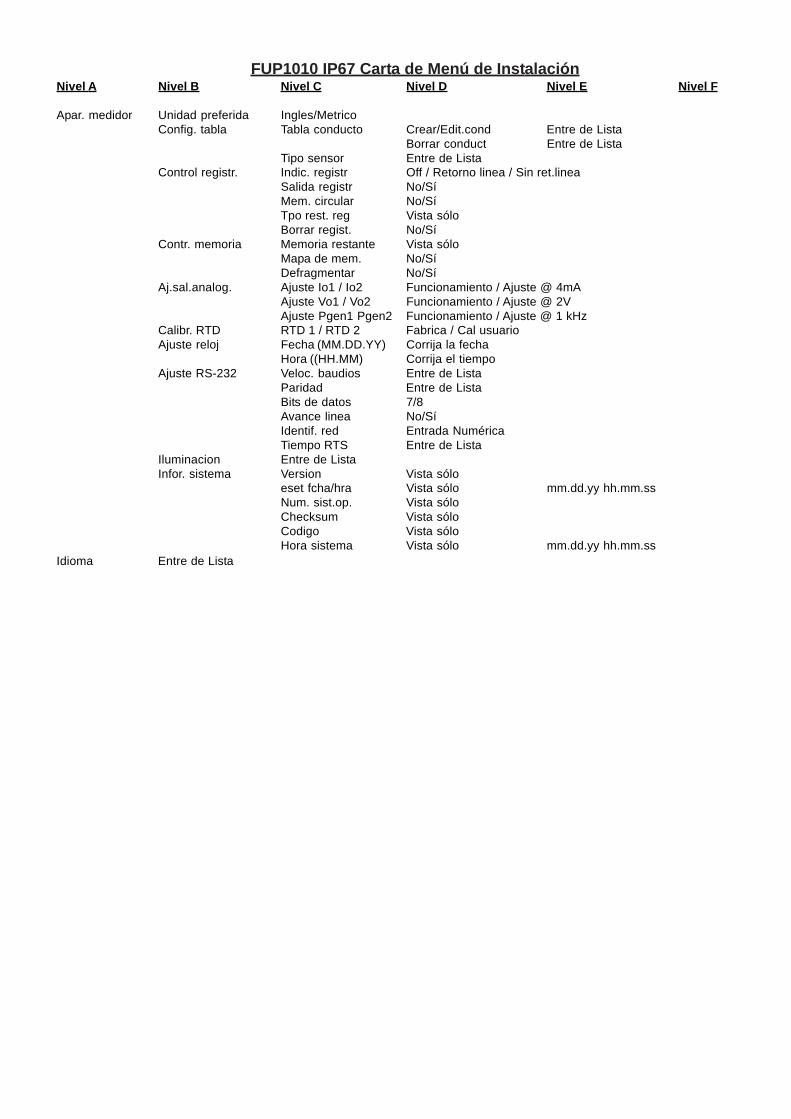
FUP1010 IP67 Carta de Menú de InstalaciónNivel A Nivel B Nivel C Nivel D Nivel E Nivel F
Apar. medidor Unidad preferida Ingles/MetricoConfig. tabla Tabla conducto Crear/Edit.cond Entre de Lista
Borrar conduct Entre de ListaTipo sensor Entre de Lista
Control registr. Indic. registr Off / Retorno linea / Sin ret.lineaSalida registr No/SíMem. circular No/SíTpo rest. reg Vista sóloBorrar regist. No/Sí
Contr. memoria Memoria restante Vista sóloMapa de mem. No/SíDefragmentar No/Sí
Aj.sal.analog. Ajuste Io1 / Io2 Funcionamiento / Ajuste @ 4mAAjuste Vo1 / Vo2 Funcionamiento / Ajuste @ 2VAjuste Pgen1 Pgen2 Funcionamiento / Ajuste @ 1 kHz
Calibr. RTD RTD 1 / RTD 2 Fabrica / Cal usuarioAjuste reloj Fecha (MM.DD.YY) Corrija la fecha
Hora ((HH.MM) Corrija el tiempoAjuste RS-232 Veloc. baudios Entre de Lista
Paridad Entre de ListaBits de datos 7/8Avance linea No/SíIdentif. red Entrada NuméricaTiempo RTS Entre de Lista
Iluminacion Entre de ListaInfor. sistema Version Vista sólo
eset fcha/hra Vista sólo mm.dd.yy hh.mm.ssNum. sist.op. Vista sóloChecksum Vista sóloCodigo Vista sóloHora sistema Vista sólo mm.dd.yy hh.mm.ss
Idioma Entre de Lista
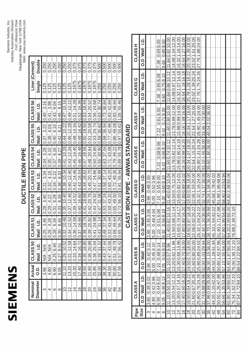
CL
AS
S 5
0N
om
inal
Dia
met
er
3 4 6 8 10 12 14 16 18 20 24 30 36 42 48 54
N/A
N
/AN
/A
N/A
0.25
6.4
00.
27 8
.51
0.29
10.
520.
31 1
2.58
0.33
14.
640.
34 1
6.72
0.35
18.
800.
36 2
0.88
0.38
25.
040.
39 3
1.22
0.43
37.
440.
47 4
3.56
0.51
49.
780.
57 5
6.42
Wal
l I.
D.
DU
CT
ILE
IR
ON
PIP
E
Act
ual
O.D
.
3.96
4.80
6.90
9.05
11.1
013
.20
15.3
017
.40
19.5
021
.60
25.8
032
.00
38.3
044
.50
50.8
057
.56
CL
AS
S 5
1
0.25
3.
460.
26
4.28
0.28
6.
340.
30
8.45
0.32
10.
460.
34 1
2.52
0.36
14.
580.
37 1
6.66
0.38
18.
740.
39 2
0.82
0.41
24.
980.
43 3
1.14
0.48
37.
340.
53 4
3.44
0.58
49.
640.
65 5
6.26
Wal
l I.
D.
CL
AS
S 5
2
0.28
3.
400.
29
4.22
0.31
6.
280.
33
8.39
0.35
10.
400.
37 1
2.46
0.39
14.
520.
40 1
6.60
0.41
18.
680.
42 2
0.76
0.44
24.
920.
47 3
1.06
0.53
37.
240.
59 4
3.32
0.65
49.
500.
73 5
6.10
Wal
l I.
D.
CL
AS
S 5
3
0.31
3.
340.
32
4.16
0.34
6.
220.
36
8.33
0.38
10.
340.
40 1
2.40
0.42
14.
460.
43 1
6.54
0.44
18.
620.
45 2
0.70
0.47
24.
860.
51 3
0.99
0.58
37.
140.
65 4
3.20
0.72
49.
360.
81 5
5.94
Wal
l I.
D.
CL
AS
S 5
4
0.34
3.
280.
35
4.10
0.37
6.
160.
39
8.27
0.41
10.
280.
43 1
2.34
0.45
14.
400.
46 1
6.48
0.47
18.
560.
48 2
0.64
0.50
24.
800.
55 3
0.90
0.63
37.
040.
71 4
3.08
0.79
49.
220.
89 5
5.78
Wal
l I.
D.
CL
AS
S 5
5
0.37
3.
220.
38
4.04
0.40
6.
100.
42
8.21
0.44
10.
220.
46 1
2.28
0.48
14.
340.
49 1
6.42
0.50
18.
500.
51 2
0.58
0.53
24.
740.
59 3
0.82
0.68
36.
940.
77 4
2.96
0.86
49.
080.
97 5
5.62
Wal
l I.
D.
0.40
3.
160.
41
3.98
0.43
6.
040.
45
8.15
0.47
10.
160.
49 1
2.22
0.51
14.
280.
52 1
6.36
0.53
18.
440.
54 2
0.52
0.56
24.
680.
63 3
0.74
0.73
36.
840.
83 4
2.84
0.93
48.
941.
05 5
5.46
Wal
l I.
D.
CL
AS
S 5
6
0.12
50.
250
0.12
50.
250
0.12
50.
250
0.12
50.
250
0.12
50.
250
0.12
50.
250
0.18
750.
375
0.18
750.
375
0.18
750.
375
0.18
750.
375
0.18
750.
375
0.25
00.
500
0.25
00.
500
0.25
00.
500
0.25
00.
500
0.25
00.
500
Sin
gle
D
ou
ble
Lin
er (
Cem
ent)
Sie
men
s In
dust
ry, I
nc.
Indu
stry
Aut
omat
ion
Div
isio
nC
oC U
ltras
onic
Flo
wH
aupp
auge
, New
Yor
k 11
788
US
AW
eb:
ww
w.u
sa.s
iem
ens.
com
CL
AS
S A
Pip
eS
ize
3 4 6 8 10 12 14 16 18 20 24 30 36 42 48 54 60 72 84
3.80
0.
39 3
.02
4.80
0.
42 3
.96
6.90
0.
44 6
.02
9.05
0.
46 8
.13
11.1
0 0.
50 1
0.10
13.2
0 0.
54 1
2.12
15.3
0 0.
57 1
4.16
17.4
0 0.
60 1
6.20
19.5
0 0.
64 1
8.22
21.6
0 0.
67 2
0.26
25.8
0 0.
76 2
4.28
31.7
4 0.
88 2
9.98
37.9
6 0.
99 3
5.98
44.2
0 1.
10 4
2.00
50.5
0 1.
26 4
7.98
56.6
6 1.
35 5
3.96
62.8
0 1.
39 6
0.02
75.3
4 1.
62 7
2.10
87.5
4 1.
72 8
4.10
O.D
Wal
l I.
D.
CL
AS
S B
3.96
0.
42 3
.12
5.00
0.
45 4
.10
7.10
0.
48 6
.14
9.05
0.
51 8
.03
11.1
0 0.
57 9
.96
13.2
0 0.
62 1
1.96
15.3
0 0.
66 1
3.96
17.4
0 0.
70 1
6.00
19.5
0 0.
75 1
8.00
21.6
0 0.
80 2
0.00
25.8
0 0.
89 2
4.02
32.0
0 1.
03 2
9.94
38.3
0 1.
15 3
6.00
44.5
0 1.
28 4
1.94
50.8
0 1.
42 4
7.96
57.1
0 1.
55 5
4.00
64.4
0 1.
67 6
0.06
76.0
0 1.
95 7
2.10
88.5
4 2.
22 8
4.10
O.D
Wal
l I.
D.
CL
AS
S C
3.96
0.
45 3
.06
5.00
0.
48 4
.04
7.10
0.
51 6
.08
9.30
0.
56 8
.18
11.4
0 0.
62 1
0.16
13.5
0 0.
68 1
2.14
15.6
5 0.
74 1
4.17
17.8
0 0.
80 1
6.20
19.9
2 0.
87 1
8.18
22.0
6 0.
92 2
0.22
26.3
2 1.
04 2
4.22
32.4
0 1.
20 3
0.00
38.7
0 1.
36 3
9.98
45.1
0 1.
54 4
2.02
51.4
0 1.
71 4
7.98
57.8
0 1.
90 5
4.00
64.2
0 2.
00 6
0.20
76.8
8 2.
39 7
2.10
O.D
Wal
l I.
D.
CL
AS
S D
3.96
0.
48 3
.00
5.00
0.
52 3
.96
7.10
0.
55 6
.00
9.30
0.
60 8
.10
11.4
0 0.
68 1
0.04
13.5
0 0.
75 1
2.00
15.6
5 0.
82 1
4.01
17.8
0 0.
89 1
6.02
19.9
2 0.
96 1
8.00
22.0
6 1.
03 2
0.00
26.3
2 1.
16 2
4.00
32.7
4 1.
37 3
0.00
39.1
6 1.
58 3
6.00
45.5
8 1.
78 4
2.02
51.9
8 1.
96 4
8.06
58.4
0 2.
23 5
3.94
64.8
2 2.
38 6
0.06
O.D
Wal
l I.
D.
CL
AS
S E
7.22
0.
58 6
.06
9.42
0.
66 8
.10
11.6
0 0.
74 1
0.12
13.7
8 0.
82 1
2.14
15.9
8 0.
90 1
4.18
18.1
6 0.
98 1
6.20
20.3
4 1.
07 1
8.20
22.5
4 1.
15 2
0.24
26.9
0 1.
31 2
4.28
33.1
0 1.
55 3
0.00
39.6
0 1.
80 3
6.00
O.D
Wal
l I.
D.
CL
AS
S F
7.22
0.
61 6
.00
9.42
0.
71 8
.00
11.6
0 0.
80 1
0.00
13.7
8 0.
89 1
2.00
15.9
8 0.
99 1
4.00
18.1
6 1.
08 1
6.00
20.3
4 1.
17 1
8.00
22.5
4 1.
27 2
0.00
26.9
0 1.
45 2
4.00
33.4
6 1.
73 3
0.00
40.0
4 2.
02 3
6.00
O.D
Wal
l I.
D.
CL
AS
S G
7.38
0.
65 6
.08
9.60
0.
75 8
.10
11.8
4 0.
86 1
0.12
14.0
8 0.
97 1
2.14
16.3
2 1.
07 1
4.18
18.5
4 1.
18 1
6.18
20.7
8 1.
28 1
8.22
23.0
2 1.
39 2
0.24
27.7
6 1.
75 2
4.26
O.D
Wal
l I.
D.
CL
AS
S H
7.38
0.
69 6
.00
9.60
0.
80 8
.00
11.8
4 0.
92 1
0.00
14.0
8 1.
04 1
2.00
16.3
2 1.
16 1
4.00
18.5
4 1.
27 1
6.00
20.7
8 1.
39 1
8.00
23.0
2 1.
51 2
0.00
27.7
6 1.
88 2
4.00
O.D
Wal
l I.
D.
CA
ST
IRO
N P
IPE
- A
WW
A S
TAN
DA
RD

PIP
E W
EIG
HT
FO
RM
UL
A F
OR
ST
EE
L P
IPE
(lb
s p
er f
oo
t)
10.6
8 (D
-t) t,
whe
re D
=Out
side
Dia
met
er a
nd t=
Wal
l Thi
ckne
ss
Thes
e m
ater
ials
are
gen
eral
ly a
vaila
ble
in S
ched
ules
40
and
80 o
nly.
| W
all T
hick
ness
of S
ched
ule
5S &
10S
doe
s no
t per
mit
thre
adin
g in
acco
rdan
ce w
ith th
e A
mer
ican
Sta
ndar
d fo
r Pip
e Th
read
s (A
SA
No.
B2.
1)
Wal
l thi
ckne
ss id
entic
al w
ith th
ickn
ess
of “S
tand
ard
Wei
ght”
pipe
.
^ W
all T
hick
ness
iden
tical
with
thic
knes
s of
“Ext
ra-H
eavy
” pip
e.* T
hese
do
not c
onfo
rm to
Am
eric
an S
tand
ard
B36
. 10.
24.0
0023
.563
0.21
823
.500
0.25
0
Sch
ed.
0.84
01.
050
0.71
00.
920
0.06
50.
065
0.67
40.
884
0.08
30.
083
0.62
20.
824
0.10
90.
113
0.54
60.
742
^.1
47^
.154
1/2
3/4
STA
INL
ES
S S
TE
EL
, H
AS
TE
LL
OY
“C
” &
TIT
AN
IUM
PIP
ES
ize
O.D
.I.D
.W
all
I.D.
Wal
l
5S|
10
S|
40
S
80
S
I.D.
Wal
lI.D
.W
all
1.31
51.
660
1.18
51.
530
0.06
50.
065
1.09
71.
442
0.10
90.
109
1.04
91.
380
0.13
30.
140
0.95
71.
278
^.1
79^
.191
11
1/4
1.90
02.
375
1.77
02.
245
0.06
50.
065
1.68
22.
157
0.10
90.
109
1.61
02.
067
0.14
50.
154
1.50
01.
939
^.2
00^
.218
1 1/
22
2.87
53.
500
2.70
93.
334
0.08
30.
083
2.63
53.
260
0.12
00.
120
2.46
93.
068
0.20
30.
216
2.32
32.
900
^.2
76^
.300
2 1/
23
4.00
04.
500
3.83
44.
334
0.08
30.
083
3.76
04.
260
0.12
00.
120
3.54
84.
026
0.22
60.
237
3.36
43.
826
^.3
18^
.337
3 1/
24
5.56
36.
625
5.34
56.
407
0.10
90.
109
5.29
56.
357
0.13
40.
134
5.04
76.
065
0.25
80.
280
4.81
35.
761
^.3
75^
.432
56
8.62
510
.750
8.40
710
.482
0.10
90.
134
8.32
910
.420
0.14
80.
165
7.98
110
.020
0.32
20.
365
7.62
59.
750
^.5
00^
.500
81
0
12.7
5014
.000
12.4
3813
.688
0.15
60.
156
12.3
9013
.624
0.18
00.
188
12.0
00*
.375
11.7
50*
.500
12
14
16.0
0018
.000
15.6
7017
.670
0.16
50.
165
15.6
2417
.624
0.18
80.
188
16
18
20.0
0022
.000
19.6
3421
.624
0.18
80.
188
19.5
6421
.564
0.21
80.
218
20
22
24
7.00
1 8
.750
10.5
0011
.500
13.1
2414
.876
16.5
0018
.250
19.8
76
3.62
44.
563
5.50
17.
189
9.06
410
.750
11.8
1413
.564
15.2
5017
.000
18.7
5020
.376
7.43
9 9
.314
11.0
6412
.126
13.9
3815
.688
17.4
3819
.250
20.9
38
7.81
3 9
.750
11.6
2612
.814
14.6
8816
.500
18.3
7620
.250
22.0
64
O.D
.I.D
.W
all
Pip
e1/
2
CA
RB
ON
ST
EE
L a
nd
PV
C P
IPE
Siz
e
I.D I.D.
Wal
l
11
1/2
2 1/
24
6
Stan
d-ar
dI.D
.Ex
traSt
rong
(XS
)
^.1
47^
.154
^.1
79^
.191
^.2
00^
.218
^.2
76^
.300
^.3
18^
.337
^.3
75^
.432
^.5
000.
593
0.68
70.
750
0.84
30.
937
1.03
11.
125
1.21
8
Dou
ble
Extra
Stro
ng(X
XS
)Sc
hed.
10
Wal
l
Wal
l
I.D.
Wal
lSc
hed.
20I.D
.W
all
Sche
d.30
I.D.
Wal
lSc
hed.
40I.D
.W
all
Sche
d.60
I.D.
Wal
lSc
hed.
80I.D
.W
all
Sche
d.10
0I.D
.W
all
Sche
d.12
0I.D
.W
all
Sche
d.14
0I.D
.W
all
Sche
d.16
0
3/4
0.84
01.
050
1.31
51.
660
1.90
02.
375
2.87
53.
500
4.00
04.
500
5.56
36.
625
8.62
510
.750
12.7
5014
.000
16.0
0018
.000
20.0
0022
.000
24.0
0026
.000
28.0
0030
.000
32.0
0034
.000
36.0
0042
.000
0.10
90.
113
0.13
30.
140
0.14
50.
154
0.20
30.
216
0.22
60.
237
0.25
80.
280
0.32
20.
365
0.40
60.
438
^.5
000.
562
0.59
30.
687
0.25
00.
250
0.25
00.
312
0.31
20.
312
0.37
50.
375
0.37
5^
.500
^.5
00^
.500
^.5
00^
.500
^.5
00^
.500
1 1/
42
33
1/2
58
1012
1416
1824
2826
3032
3436
4220
22
0.62
20.
824
1.04
91.
380
1.61
02.
067
2.46
93.
068
3.54
84.
026
5.04
76.
065
7.98
110
.020
12.0
0013
.250
15.2
5017
.250
19.2
5021
.250
23.2
5025
.250
27.2
5029
.250
31.2
5033
.250
35.2
5041
.250
0.10
90.
113
0.13
30.
140
0.14
50.
154
0.20
30.
216
0.22
60.
237
0.25
80.
280
0.32
2 0
.365
0.3
75 0
.375
0.3
75 0
.375
0.3
75 0
.375
0.3
75 0
.375
0.3
75 0
.375
0.37
50.
375
0.37
5* .
375
0.54
60.
742
0.95
71.
278
1.50
01.
939
2.32
32.
900
3.36
43.
826
4.81
35.
761
7.62
5 9
.750
11.7
5013
.000
15.0
0017
.000
19.0
0021
.000
23.0
0025
.000
27.0
0029
.000
31.0
0033
.000
35.0
0041
.000
0.14
70.
154
0.17
90.
191
0.20
00.
218
0.27
60.
300
0.31
80.
337
0.37
50.
432
0.50
0 0
.500
0.5
00 0
.500
0.5
00 0
.500
0.5
00 0
.500
0.5
00 0
.500
0.5
00 0
.500
0.50
00.
500
0.50
0* .
500
0.25
20.
434
0.59
90.
896
1.10
01.
503
1.77
12.
300
2.72
83.
152
4.06
34.
897
6.87
5 8
.750
10.7
50
0.29
40.
308
0.35
80.
382
0.40
00.
436
0.55
20.
600
0.63
60.
674
0.75
00.
864
0.87
5 1
.000
1.0
00
13.5
0015
.500
17.5
0019
.500
21.5
0023
.500
25.3
7627
.376
29.3
7631
.376
33.3
7635
.376
0.2
50 0
.250
0.2
50 0
.250
0.2
50 0
.250
0.3
12 0
.312
0.3
12 0
.312
0.3
12 0
.312
8.12
510
.250
12.2
5013
.376
15.3
7617
.376
19.2
5021
.250
23.2
5025
.000
27.0
0029
.000
31.0
0033
.000
35.0
0041
.000
8.07
110
.136
12.0
9013
.250
15.2
5017
.124
19.0
0021
.000
22.8
7626
.750
28.7
5030
.750
32.7
5034
.750
40.7
500.
277
0.30
70.
330
0.37
50.
375
0.43
8^
.500
^.5
000.
562
0.62
50.
625
0.62
50.
625
0.62
5* .
625
0.62
20.
824
1.04
91.
380
1.61
02.
067
2.46
93.
068
3.54
84.
026
5.04
76.
065
7.98
110
.020
11.9
3813
.124
15.0
0016
.876
18.1
8422
.626
0.40
6 ^
.500
0.5
62 0
.593
0.6
56 0
.750
0.8
12 0
.875
0.9
680.
546
0.74
20.
957
1.27
81.
500
1.93
92.
323
2.90
03.
364
3.82
64.
813
5.76
17.
625
9.5
6411
.376
12.5
0014
.314
16.1
2617
.938
19.7
5021
.564
0.59
3 0
.718
0.8
43 0
.937
1.0
31 1
.156
1.2
81 1
.375
1.5
31
0.43
80.
500
0.56
20.
718
0.84
3 1
.000
1.0
93 1
.218
1.3
75 1
.500
1.6
25 1
.812
0.81
2 1
.000
1.1
25 1
.250
1.4
38 1
.562
1.7
50 1
.875
2.0
620.
466
0.61
40.
815
1.16
01.
338
1.68
92.
125
2.62
43.
438
4.31
35.
189
6.81
3 8
.500
10.1
2611
.188
12.8
1414
.438
16.0
6417
.750
19.3
140.
187
0.21
80.
250
0.25
00.
281
0.34
30.
375
0.43
80.
531
0.62
50.
718
0.90
6 1
.125
1.3
12 1
.406
1.5
93 1
.781
1.9
68 2
.125
2.3
43
Siz
e1
02
02
42
4
O.D
.10
.750
20.0
0024
.000
24.0
00I.D
.10
.192
19.3
7523
.375
22.1
26W
all
0.27
90.
312
0.31
20.
937
The
abov
e si
zes
are
prod
uced
by
pipe
mills
but
dim
ensi
ons
do n
ot c
onfo
rm to
any
reg
ular
sta
n-da
rd o
r sch
edul
e.
NO
N-S
TAN
DA
RD
CA
RB
ON
Sie
men
s In
dust
ry In
c.In
dust
ry A
utom
atio
n D
ivis
ion
Coc
Ultr
ason
ic F
low
Hau
ppau
ge, N
ew Y
ork
1178
8 U
SA
Web
: ww
w.u
sa.s
iem
ens.
com

Sonic Velocity Relative to Temperature of Pure Water Temperature Velocity Temperature Velocity Temperature Velocity F C M/S F C M/S F C M/S 0.0 -17.8 1292.45 100.0 37.8 1525.03 200.0 93.3 1548.38 2.0 -16.67 1300.64 102.0 38.9 1526.99 202.0 94.4 1547.60 4.0 -15.55 1308.63 104.0 40.0 1528.86 204.0 95.6 1546.78 6.0 -14.44 1316.44 106.0 41.1 1530.67 206.0 96.7 1547.60 8.0 -13.33 1324.06 108.0 42.2 1532.4 208.0 97.8 1545.02
10.0 -12.22 1331.50 110.0 43.3 1534.06 210.0 98.9 1544.08 12.0 -11.00 1338.77 112.0 44.4 1535.64 212.0 100.0 1543.11 14.0 -10.0 1345.86 114.0 45.6 1537.16 214.0 101.1 1542.10 16.0 -8.89 1352.78 116.0 46.7 1538.61 216.0 102.2 1541.05 18.0 -7.78 1359.53 118.0 47.8 1539.99 218.0 103.3 1539.97 20.0 -6.67 1366.12 120.0 48.9 1541.30 220.0 104.4 1538.85 22.0 -5.56 1372.55 122.0 50.0 1542.55 222.0 105.6 1537.70 24.0 -4.44 1378.82 124.0 51.1 1543.74 224.0 106.7 1536.51 26.8 -3.33 1384.94 126.0 52.2 1544.86 226.0 107.8 1535.29 28.0 -2.22 1390.90 128.0 53.3 1545.91 228.0 108.9 1534.03 30.0 -1.11 1396.72 130.0 54.4 1546.91 230.0 110.0 1532.74 32.0 0.0 1402.39 132.0 55.6 1547.84 232.0 111.1 1531.42 34.0 1.11 1407.91 134.0 56.7 1548.72 234.0 112.2 1530.06 36.0 2.22 1413.30 136.0 57.8 1549.53 236.0 113.3 1528.67 38.0 3.33 1418.55 138.0 58.9 1550.29 238.0 114.4 1527.26 40.0 4.44 1423.66 140.0 60.0 1550.99 240.0 115.6 1525.81 42.0 5.56 1428.64 142.0 61.1 1551.63 242.0 116.7 1524.33 44.0 6.67 1433.48 144.0 62.2 1552.21 244.0 117.8 1522.83 46.0 7.78 1438.20 146.0 63.3 1552.74 246.0 118.9 1521.29 48.0 8.89 1442.80 148.0 64.4 1553.22 248.0 120.0 1519.73 50.0 10.0 1447.27 150.0 65.6 1553.64 250.0 121.1 1518.14 52.0 11.11 1451.62 152.0 66.7 1554.01 260.0 126.7 1507.00 54.0 12.22 1455.85 154.0 67.8 1554.32 270.0 132.2 1497.00 56.0 13.33 1459.97 156.0 68.9 1554.59 280.0 137.8 1487.00 58.0 14.44 1463.97 158.0 70.0 1554.80 290.0 143.3 1476.00 60.0 .15.56 1467.86 160.0 71.1 1554.98 300.0 148.9 1465.00 62.0 16.67 1471.64 162.0 72.2 1555.07 310.0 154.4 1453.00 64.0 17.89 1475.31 164.0 73.3 1555.13 320.0 160.0 1440.00 66.0 18.89 1478.88 166.0 74.4 1555.15 330.0 165.6 1426.00 68.0 20.0 1482.34 168.0 75.6 1555.11 340.0 171.1 1412.00 70.0 21.1 1485.70 170.0 76.7 1555.03 350.0 176.7 1398.00 72.0 22.2 1488.96 172.0 77.8 1554.90 360.0 182.2 1383.00 74.0 23.3 1492.13 174.0 78.9 1554.72 370.0 187.8 1368.00 76.0 24.4 1495.19 176.0 80.0 1554.49 380.0 193.3 1353.00 78.0 25.6 1498.16 178.0 81.1 1554.22 390.0 198.9 1337.00 80.0 26.7 1501.04 180.0 82.2 1553.91 400.0 204.4 1320.00 82.0 27.8 1503.82 182.0 83.3 1553.55 410.0 210.0 1302.00 84.0 28.9 1506.52 184.0 84.4 1553.14 420.0 215.6 1283.00 86.0 30.0 1509.13 186.0 85.6 1552.70 430.0 221.1 1264.00 88.0 31.1 1511.65 188.0 86.7 1552.21 440.0 226.7 1244.00 90.0 32.2 1514.08 190.0 87.8 1551.67 450.0 232.2 1220.00 92.0 33.3 1516.44 192.0 88.9 1551.10 460.0 237.8 1200.00 94.0 34.4 1518.70 194.0 90.0 1550.48 470.0 243.3 1180.00 96.0 35.6 1520.89 196.0 91.1 1549.82 480.0 248.9 1160.00 98.0 36.7 1523.00 198.0 92.2 1549.12 490.0 254.4 1140.00
Siemens Industry, Inc.Industry Automation Division
CoC Ultrasonic FlowHauppauge, New York 11788 USA
Web: www.usa.siemens.com
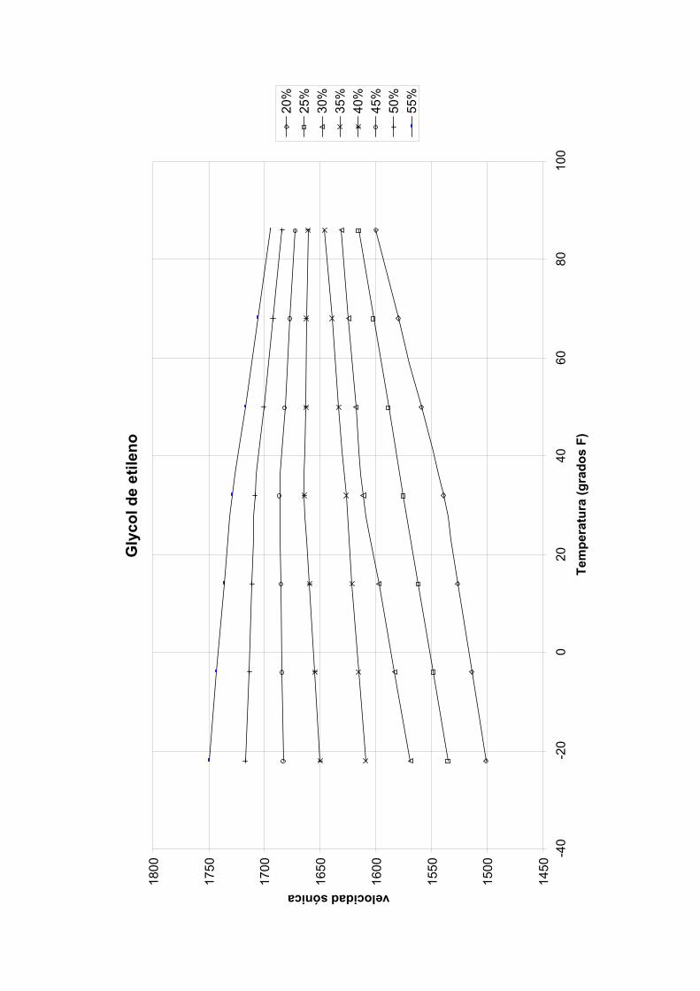
velocidad sónica
1800
1750
1700
1650
1600
1550
1500
1450
-40
Gly
col d
e et
ileno
55%
50%
45%
40%
35%
30%
25%
20%
-20
080
2040
6010
0Te
mpe
ratu
ra (g
rado
s F)


Get more information
www.siemens.com/flow
www.siemens.com/processautomation
Subject to change without prior noticeOrder No.: CQO:QSG003 Revision 05Printed in the USA© Siemens AG 01.2013
Siemens Industry, Inc.Industry Automation DivisionCoC Ultrasonic FlowHauppauge, NY 11788USA