Embed Size (px)
Citation preview
1
Fundición Nodular S.A. SPAIN
Defects presented by the new roll generations such as HSS, MHSS, semi-HSS in relation
with the natural hydrodynamic of the vertical centrifugal casting.
ROLLS CHINA 2008
Juan Llano. Sales Director Fundición Nodular S.A. José Luis Gonzalez.Technical Director Fundición Nodular S.A. Beatriz Pejenaute i+d Manager Fundición Nodular S.A. J.C. Werquin Technical Adviser Fundición Nodular S.A.
ABSTRACT
The vertical centrifugal casting for rolling mill rolls has been developed first in France at the end of the sixties. This development has permitted the very rapid development of High Chrome Iron rolls in Europe. This development has been made very smoothly because the high heat quantity developed during eutectic solidification allows brutal variations of shell growth speed without influence on final structure. Inversely, the new roll generations have no or very little eutectic heat generation and the natural hydrodynamic of the process induces defects such as porosities type 1 or 2 and also internal cracks in the shell called “reflectors” Porosities type 3 are also possible when core pouring starts too early and when the core is poured at a too high temperature the wash of the shell introduces carbide former elements in the core.
The paper describes the natural hydrodynamic of the vertical process, explains all shell defects such as porosities type 1, 2 and 3 as well as the internal shell cracks generation. The results of the new vertical spin casting process with the so called Aided Hydrodynamic (HARP process) for the shell pouring and the new patented method for core pouring, eliminating completely the shell wash is presented.
2
1.Main characteristics of the traditional Vertical Spin Casting (VSC) technology. The first VSC Hi Chrome iron hot strip mill work roll has been poured in 1969, in Berlaimont (France)( Ref.1) after a long technological research on a small experimental vertical caster starting in 1967. The basic concepts validated during this research period are now used by all rollmakers of the world using the vertical spin casting technology. For this reason, it is justified to speak in this paper about “the traditional pouring method” 1.1 The pouring pipe The pouring of the shell at the top of the barrel has been finally retained as the best solution to avoid skin defects. The same principle has also been retained for first core pouring to improve the bonding conditions at the top of the barrel. There are some variations for the number, the dimensions and the angle of the jets starting from the pipe bottom brick from one rollmaker to the other but the hydrodynamic of shell pouring remains the same. 1.2 The thermocouple The knowledge of the interface temperature variation after shell pouring is rapidly appeared as fundamental. The vertical position of the caster permitted to use very easily a thermocouple placed at a fixed position and to compare the thermocouple record to the thermal analysis made on the shell metal just before pouring. The thermocouple sees perfectly the solidus of the shell interface and gives the signal for core pouring, for example, at shell “just solidified”. This is a clear advantage of the VSC compared with other centrifugal processes. Of course, for shell materials with no or little eutectic heat emission, it is a little bit more complicated to optimize the signal of core pouring. For this purpose, we use an experimental method introducing a “form factor” calculated for each roll dimensions. This is important notably for plate mill work rolls due to their long barrel length. 1.3 The flux Most of the rollmakers use a high melting temperature flux such as AS72 (Air Liquide) for high Chrome Iron rolls and relatively lower melting point fluxes for ICDP rolls. But there are many possible ways of flux introduction in the mold, solid or liquid, through the pouring pipe or directly, during or after shell pour.
2.Parameters of the thermal balance for shell core bonding 2.1 The interface temperature
3
The interface temperature record allows to choice accurately the right moment to pour the core. Or the interface is just “consolidated” and this means that some residual eutectic liquid remains between the dendrites. Or the shell is just solidified (a few degrees after the solidus) or the shell is fully solidified (some tens of degrees after solidus)
Depending on the roll quality, the best choice is made by the rollmaker in order to optimize the thermal balance. In other words, the interface temperature is one of the two parameters optimizing the solid diffusion exchanges between shell and core elements as we will see later.
2.2 The core 1 temperature
The core temperature is the second key parameter of the thermal balance. Rollmakers use normally one ladle for the core and depending on the interface temperature, the core is said cold (liquidus + 50°C) or hot (liquidus + 130°C) or very hot (liquidus + ≥130°C)
The core temperature is also the key parameter of the shell wash by the core. A hot core always washes the shell, notably at the bottom part, and if this wash is too strong, the core pollution by the carbide former elements of the shell is very detrimental for the nodular core leading to roll breakage or at least to high stresses of the entire roll.
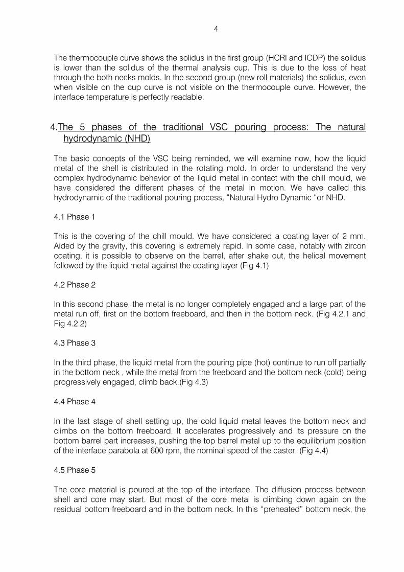
3.The thermocouple curve in relation with thermal analysis curve 3.1 Recall of thermal analysis curves for roll materials The following figures, just for memory, show the thermal analysis curves for different rolls materials. The figure 3.1.1 is the iron base shell material while the figure 3.1.2 corresponds to the new roll materials.
3.2 Thermocouple curves
ICDP HCRI
1450°C
1350°C
1250°C
1100°C
1400°C
1300°C
1200°C
1150°C
1272°
1234°
1234°
1214°
2.8C-18Cr
1450°C
1350°C
1250°C
1100°C
1400°C
1300°C
1200°C
1150°C
1214°
1389°
1414°
1190°
1440°
1143°
γ −MC
γ −M²C1155°
1190°
1320°
1.3C-12Cr HCrS
2C 5V Mo Cr HSS
0.6C-10Crsemi- HSS
0.8C-13Cr HCrS
Porosities and internal cracks are ignored with the first group of materials (fig 3.1.1.) due to the strong eutectic heat emission. In the HCrS group, the high carbon (1.3C) is not sensible to the internal cracks as well as the high carbon HSS (enough eutectic liquid)
Fig 3.1.1. Fig 3.1.2.
4
The thermocouple curve shows the solidus in the first group (HCRI and ICDP) the solidus is lower than the solidus of the thermal analysis cup. This is due to the loss of heat through the both necks molds. In the second group (new roll materials) the solidus, even when visible on the cup curve is not visible on the thermocouple curve. However, the interface temperature is perfectly readable.
4.The 5 phases of the traditional VSC pouring process: The natural hydrodynamic (NHD)
The basic concepts of the VSC being reminded, we will examine now, how the liquid metal of the shell is distributed in the rotating mold. In order to understand the very complex hydrodynamic behavior of the liquid metal in contact with the chill mould, we have considered the different phases of the metal in motion. We have called this hydrodynamic of the traditional pouring process, “Natural Hydro Dynamic “or NHD.
4.1 Phase 1
This is the covering of the chill mould. We have considered a coating layer of 2 mm. Aided by the gravity, this covering is extremely rapid. In some case, notably with zircon coating, it is possible to observe on the barrel, after shake out, the helical movement followed by the liquid metal against the coating layer (Fig 4.1)
4.2 Phase 2
In this second phase, the metal is no longer completely engaged and a large part of the metal run off, first on the bottom freeboard, and then in the bottom neck. (Fig 4.2.1 and Fig 4.2.2)
4.3 Phase 3 In the third phase, the liquid metal from the pouring pipe (hot) continue to run off partially in the bottom neck , while the metal from the freeboard and the bottom neck (cold) being progressively engaged, climb back.(Fig 4.3) 4.4 Phase 4 In the last stage of shell setting up, the cold liquid metal leaves the bottom neck and climbs on the bottom freeboard. It accelerates progressively and its pressure on the bottom barrel part increases, pushing the top barrel metal up to the equilibrium position of the interface parabola at 600 rpm, the nominal speed of the caster. (Fig 4.4) 4.5 Phase 5 The core material is poured at the top of the interface. The diffusion process between shell and core may start. But most of the core metal is climbing down again on the residual bottom freeboard and in the bottom neck. In this “preheated” bottom neck, the

5
hot core material accumulates and is climbing up again. At that stage, when the core material is hot, the bottom part of the shell is washed due to the double effect of the core temperature and the friction between shell and core due to the speed differential.
6
TRADITIONAL POURING PROCESS
(NHD)
PHASE #1
Chill covering by liquid metal and formation of a 12-17mm shell layer with instantaneous freezing (ISL)
Chill coating 2mm
«connected »shell
Limit of the instantaneously solidified shell layer
Fig 4.1
7
TRADITIONAL POURING PROCESS
(NHD)
PHASE #2
The instantaneously solidified layer is completed and cylindrical. The liquid metal of the jets is practically no longer dragged. (Liquid metal on hot solid)
Chill coating 2mm
Connected shell (cylindrical)
[mn]
~17 [mm]
Solidification speed[mm/mn]
Pouring speed [mm/mn]
Liquid metal (but cold) in transit in bottom neck
Fig 4.2.1.
8
ω
Fig 4.2.2
TRADITIONAL POURING PROCESS
(NHD)
PHASE #3
(with 3 jets. View from the top)
While the shell in the barrel is in acceleration phase, part of the hot metal from the jets covers and overlaps the freeboard and falls in the bottom neck mould. In the same time, cold metal from this bottom neck, climbs the freeboard again and covers the barrel. But during this phase, there is an accumulation of liquid metal in the bottom neck mould.
Liquid metal
Freeboard
Metal in bottom neck
Connected Shell (ISL)
Metal in acceleration
9
TRADITIONAL POURING PROCESS
(NHD)
PHASE #3
The cold metal coming from the bottom neck as well as the metal sustained by the bottom freeboard goes up again in the barrel. But part of the shell metal continues to fill up the bottom neck mould.
The raising of the bottom neck metal will be completed far after the end of shell pouring. (See motor intensity variation)
Liquid metal accumulates in bottom neck
Chill coating 2mm
Connected shell (cylindrical)
Jet i
Fig 4.3
10
Last metal from bottom neck
#2Porosities Zone Near interface
Thermocouple
Shell parabola at equilibrium
TRADITIONAL POURING PROCESS
(NHD)
PHASE #4
. The last liquid metal coming from bottom neck is progressively accelerated and the pressure increases on the connected shell. This pressure is transmitted through the semi - liquid of the whole connected shell.
Then at the top of the shell, a part of semi-liquid metal is squeezed from inside to outside in order to built the shell parabola at equilibrium.
If this squeezed metal is at or just under liquidus, (semi-liquid), porosities, filled with liquid flux may occur, in the last millimeters of the shell, near the interface. Of course, these porosities are interdendritic. (type 2 porosities)
Fig 4.4
Parabola bottom neck « just empty »
11
TRADITIONAL POURING PROCESS
(NHD)
PHASE #5
The core material is poured at the top of the interface. The diffusion process between shell and core may start if the two parameters of the thermal balance are correct. But most of the core metal is climbing down again on the residual bottom freeboard first and then in the bottom neck. In this “preheated” bottom neck, the hot core material accumulates and is climbing up again. At that stage, when the core material is hot, the bottom part of the shell is washed due to the double effect of the core temperature and the friction between shell and core due to the speed differential.
Possible shell wash
Shell
Fig 4.5
12
5. Formation and description of the micro porosities in relation with the NHD steps. During shell pouring, as described in the phases 2 and 3, during a short time, the two corresponding interfaces, notably at the top of the barrel were not covered with metal. During this time, solidification move on, and the interface is then recovered with cold metal coming from bottom freeboard (phase 2) or from bottom neck (phase 3). This cold metal solidifies very quickly, (equiaxed structure) and if solidification forward the two interfaces (CET –Columnar-to- Equiaxed growth Transition) is not completed, porosities occur. This is the porosities type 1. 5.1 Type 1a porosities The porosities types 1a appear during phase 2, with shell materials containing no or very little eutectic liquid, because the cold metal in unable to feed the interface shrinkage. It is frequent to meet such porosities with semi HSS and sometimes also in HSS rolls essentially on the top of the barrel. (Fig 5.1.1 & 5.1.2.) Of course, the porosities type 1, being shrinkage porosities, are void.
Fig 5.1.1 Fig 5.1.2.
Fig 5.1.3
BARREL TOP
BARREL BOTTOM
dendritic
equiaxed
polished nital etched
10 mm Porosities Type 1a
13
5.2 Type 1b porosities
The porosities type 1b follow the same mechanism as type 1a and are a lot alike. They are just at about 35 /45 mm depth, when phase 3 is under way.(Fig 5.2.1 & 5.2.2)
Fig 5.2.1 Fig 5.2.2
5.3 Type 2 porosities
The porosities types 2 are caused by squeezing the interface slurry at the top part of the barrel as shown in the phase 4. These type 2 porosities, are interdendritic and filled with flux. (Fig 5.3).They are dangerous for roll integrity, leading sometimes to shell spall.
Fig 5.3
polished nital etched
SEM picture showing flux entrapments
in interdendritic porosities
Porosities type 1b
14
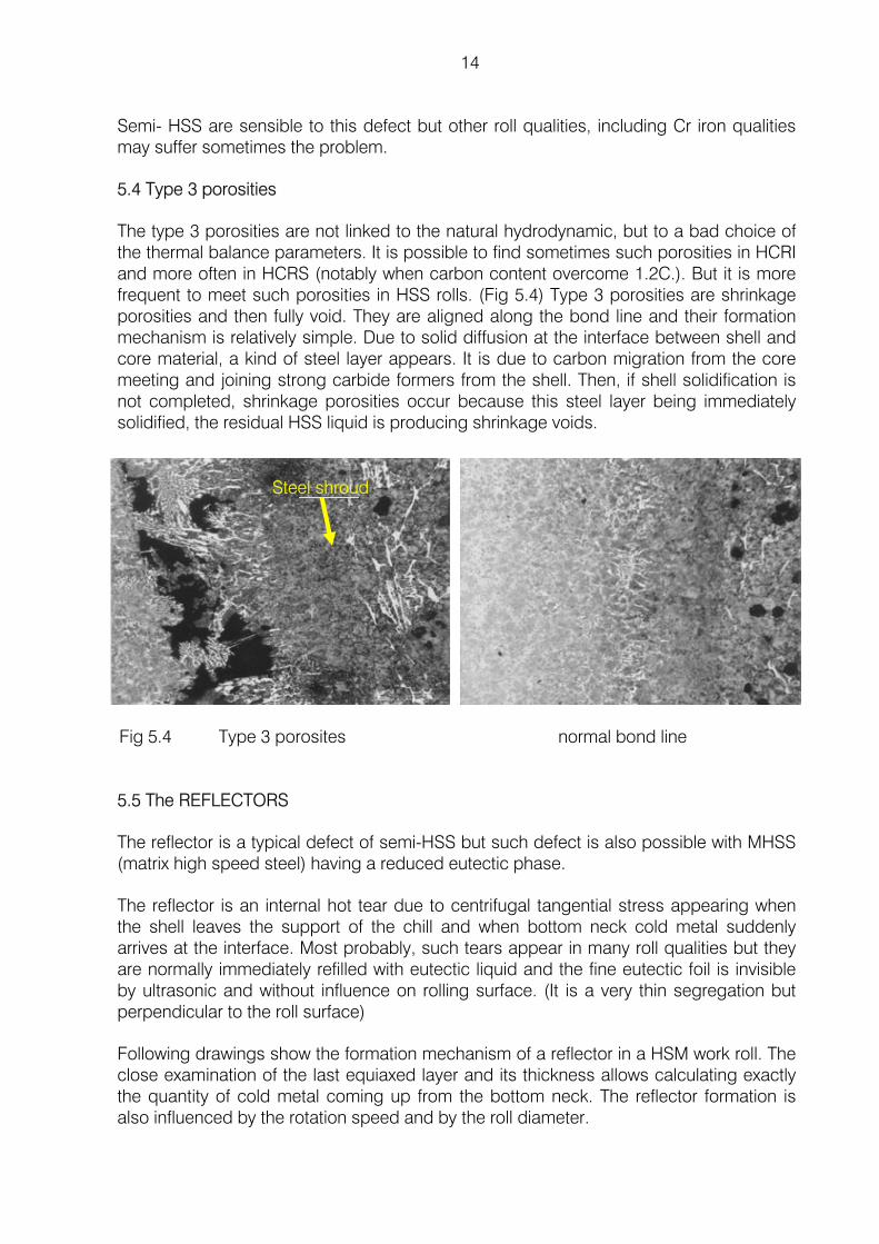
Semi- HSS are sensible to this defect but other roll qualities, including Cr iron qualities may suffer sometimes the problem.
5.4 Type 3 porosities
The type 3 porosities are not linked to the natural hydrodynamic, but to a bad choice of the thermal balance parameters. It is possible to find sometimes such porosities in HCRI and more often in HCRS (notably when carbon content overcome 1.2C.). But it is more frequent to meet such porosities in HSS rolls. (Fig 5.4) Type 3 porosities are shrinkage porosities and then fully void. They are aligned along the bond line and their formation mechanism is relatively simple. Due to solid diffusion at the interface between shell and core material, a kind of steel layer appears. It is due to carbon migration from the core meeting and joining strong carbide formers from the shell. Then, if shell solidification is not completed, shrinkage porosities occur because this steel layer being immediately solidified, the residual HSS liquid is producing shrinkage voids.
5.5 The REFLECTORS
The reflector is a typical defect of semi-HSS but such defect is also possible with MHSS (matrix high speed steel) having a reduced eutectic phase.
The reflector is an internal hot tear due to centrifugal tangential stress appearing when the shell leaves the support of the chill and when bottom neck cold metal suddenly arrives at the interface. Most probably, such tears appear in many roll qualities but they are normally immediately refilled with eutectic liquid and the fine eutectic foil is invisible by ultrasonic and without influence on rolling surface. (It is a very thin segregation but perpendicular to the roll surface)
Following drawings show the formation mechanism of a reflector in a HSM work roll. The close examination of the last equiaxed layer and its thickness allows calculating exactly the quantity of cold metal coming up from the bottom neck. The reflector formation is also influenced by the rotation speed and by the roll diameter.
Fig 5.4 Type 3 porosites normal bond line
Steel shroud

15
It is important to observe the position of the hot tear in the macrostructure of the shell. The ISL layer (~17mm) rapidly solidified and normally dendritic is completely solidified
Main NHD steps for HSM work roll
35 17
75
53 95
143
2715
861mm
4299 Kg
I2872 Kg
1427 Kg
Shrinkage gap in formation
ISL REFLECTOR
(If not enough residual eutectic liquid)
Liquid metal from bottom neck
Formation mechanism of a REFLECTOR
crack
Shell SG Core
ISL dendritic equiaxed
Fig 5.5.2. Fig 5.5
16
when the hot tearing starts. Then the crack takes place mostly in the dendritic macrostructure in formation and stops immediately when the equiaxed (cold metal from bottom neck) arrives. (Fig 5.5.2)
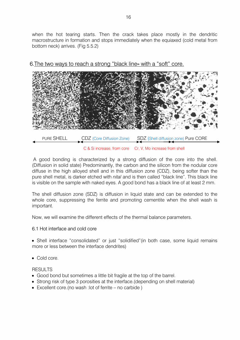
6.The two ways to reach a strong “black line» with a “soft” core.
PURE SHELL CDZ (Core Diffusion Zone) SDZ (Shell diffusion zone) Pure CORE C & Si increase, from core Cr, V, Mo increase from shell
A good bonding is characterized by a strong diffusion of the core into the shell. (Diffusion in solid state) Predominantly, the carbon and the silicon from the nodular core diffuse in the high alloyed shell and in this diffusion zone (CDZ), being softer than the pure shell metal, is darker etched with nital and is then called “black line”. This black line is visible on the sample with naked eyes. A good bond has a black line of at least 2 mm.
The shell diffusion zone (SDZ) is diffusion in liquid state and can be extended to the whole core, suppressing the ferrite and promoting cementite when the shell wash is important.
Now, we will examine the different effects of the thermal balance parameters.
6.1 Hot interface and cold core • Shell interface “consolidated” or just “solidified”(in both case, some liquid remains more or less between the interface dendrites)
• Cold core.
RESULTS • Good bond but sometimes a little bit fragile at the top of the barrel. • Strong risk of type 3 porosities at the interface.(depending on shell material) • Excellent core.(no wash :lot of ferrite – no carbide )
17
6.2 Cold interface and hot core • Shell interface “fully solidified” • Hot or very hot core.
RESULTS • Good bond. • No type 3 porosities. • Contaminated core (shell wash) • High stressed roll
6.The new pouring process: HARP (Hydro dynamically Aided Refining Process
It is known that the centrifugal casting, vertical or horizontal presents generally a non- uniform structure. The micro bands phenomenon, alternating equiaxed and dendritic structures is always present. Unfortunately such micro bands are sometimes associated with micro porosities. The segregations are also another drawback of the centrifugal casting notably in the horizontal process.
If the traditional qualities such as Indefinite Chill or High Chrome iron, even if it is possible to observe a micro banding, there are not suffering porosities problems.
The study of the natural hydrodynamic of the traditional vertical spin casting process has shown here its direct influence on micro-porosities formation when the eutectic solidification is thermally weak. That is for the new roll qualities such as semi-HSS and to a lesser extent for the HSS.
Today, a completely new pouring process associated with a new bonding system, protected by a European granted patent, (EP 1 097 753 B) has been developed by FUNDICIÓN NODULAR.
This new VSC process has been called “the harp process”
HARP means Hydro dynamically Aided Refinement Process.
7.1 Comparison between NHD and AHD (Aided HydroDynamic)
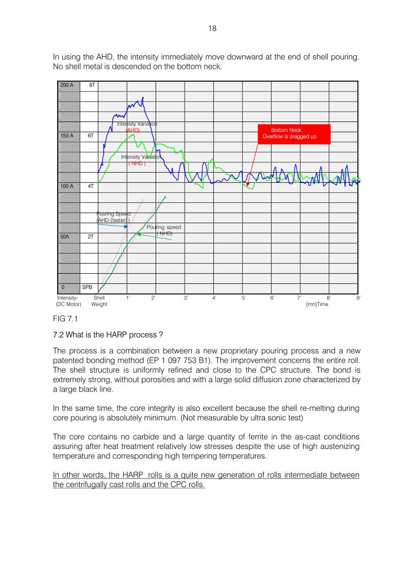
The recording of the main DC motor intensity of the caster during shell pouring brings to light the natural hydrodynamic. Systematically, the intensity is coming back to the original value (due to mechanical frictions) a certain time, after the end of pouring. The small variations around the mean value are due to thyristor speed control system, more or less stable, depending on the equipment. (Roughly the total time to reach equilibrium is twice the pouring time) (Figure 7.1)
18
In using the AHD, the intensity immediately move downward at the end of shell pouring. No shell metal is descended on the bottom neck.
200 A 8T
150 A 6T
100 A 4T
50A 2T
0 SPB Intensity- Shell 1’ 2’ 3’ 4’ 5’ 6’ 7’ 8’ 9’ (DC Motor) Weight [mn]Time
FIG 7.1
7.2 What is the HARP process ?
The process is a combination between a new proprietary pouring process and a new patented bonding method (EP 1 097 753 B1). The improvement concerns the entire roll. The shell structure is uniformly refined and close to the CPC structure. The bond is extremely strong, without porosities and with a large solid diffusion zone characterized by a large black line.
In the same time, the core integrity is also excellent because the shell re-melting during core pouring is absolutely minimum. (Not measurable by ultra sonic test)
The core contains no carbide and a large quantity of ferrite in the as-cast conditions assuring after heat treatment relatively low stresses despite the use of high austenizing temperature and corresponding high tempering temperatures.
In other words, the HARP rolls is a quite new generation of rolls intermediate between the centrifugally cast rolls and the CPC rolls.
Pouring Speed (AHD-[faster] )
Pouring speed ( NHD)
Intensity Variation ( NHD )
Intensity Variation (AHD) Bottom Neck
Overflow is dragged up
19
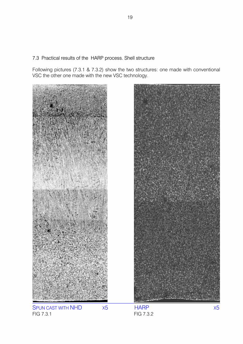
7.3 Practical results of the HARP process. Shell structure
Following pictures (7.3.1 & 7.3.2) show the two structures: one made with conventional VSC the other one made with the new VSC technology.
SPUN CAST WITH NHD X5 HARP X5 FIG 7.3.1 FIG 7.3.2
20
A very uniform and fine structure throughout the whole shell. Neither porosities nor segregation. Depending on the melting and pouring temperature, the whole shell can be also fully and uniformly dendritic, without porosities or segregation.
7.4 Practical results of the HARP process: Quality of the core
The total maximum sum of ΔCr + ΔMo + ΔV (total shell alloys pick up) in the core with a shell material of 5Cr+5Mo+5 V is 0.2 with an average value of 0.08. (Bottom neck sample)
With the same shell composition, the latest Japanese patents (ref. 2) by horizontal spin casting the shell alloys pick up is around 0.8 and then a high carbon and silicon contents are requested, increasing the risk of chunky graphite formation.
Due to this low level of core pollution, it is not necessary using very high level of silicon content in the core, and then the risk of obtaining chunky graphite is eliminated.
As example, there is a result of a HSS roll core compositions
position C Mn Si S P Cr Ni Mo Mg V Pure core
2.9 0.15 2.05 0.013 0.039 0.06 0.65 0.01 0.054 0.0
Bottom neck
3.0 0.27 1.88 0.008 0.011 0.114 0.55 0.065 0.035 0.07
ΔCr,Mo,V =0.179
0.054 0.055 0.070
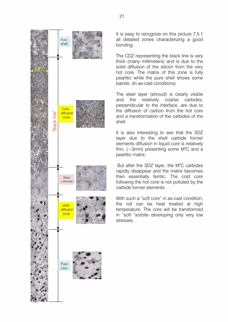
7.5 HARP roll grades The HARP® process is devoted only to the modern qualities of rolls such as semi HSS and HSS for cold and hot mill work rolls. The semi-HSS or MHSS or HSS cold mill as well as hot mill work rolls have to be heat treated at very high austenizing temperature (≥1100°C) in order to activate strongly the secondary hardening to reach a hardness level of 90 Sh C or more. Once again, only an unalloyed core, with ferrite and no carbide is compatible with this heat treatment. These low carbon grades, in the range of 0.6/0.8C, presenting no eutectic crystallisation, are very sensible to micro porosities and this defect, even very small, is not acceptable for cold rolling. The new generation of HSS rolls recently developed by FUNDICIÓN NODULAR with a new structure and a very good distribution of eutectic carbides like MC and M2C also use exclusively the HARP® process. The following picture (Fig 7.5.1) shows the new structure of shell-core transition.
21
0.7mm
Pure shell
shell diffusion zone
Core diffusion zone
Pure core
Steel « shroud »
It is easy to recognize on this picture 7.5.1 all detailed zones characterizing a good bonding.
The CDZ representing the black line is very thick (many millimeters) and is due to the solid diffusion of the silicon from the very hot core. The matrix of this zone is fully pearlitic while the pure shell shows some bainite. (In as-cast conditions)
The steel layer (shroud) is clearly visible and the relatively coarse carbides, perpendicular to the interface, are due to the diffusion of carbon from the hot core and a transformation of the carbides of the shell.
It is also interesting to see that the SDZ layer due to the shell carbide former elements diffusion in liquid core is relatively thin, (~3mm) presenting some M3C and a pearlitic matrix.
But after the SDZ layer, the M3C carbides rapidly disappear and the matrix becomes then essentially ferritic. The cold core following the hot core is not polluted by the carbide former elements.
With such a “soft core” in as-cast condition, the roll can be heat treated at high temperature. The core will be transformed in “soft “sorbite developing only very low stresses.
Fig 7.5.1
"Bla
ck li
ne"
22
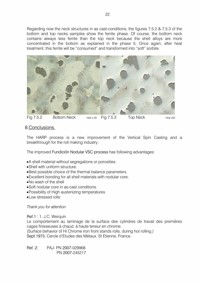
Regarding now the neck structures in as cast-conditions, the figures 7.5.2 & 7.5.3 of the bottom and top necks samples show the ferrite phase. Of course, the bottom neck contains always less ferrite than the top neck because the shell alloys are more concentrated in the bottom as explained in the phase 5. Once again, after heat treatment, this ferrite will be “consumed” and transformed into “soft” sorbite.
Fig 7.5.2 Bottom Neck nital x 50 Fig 7.5.3 Top Neck nital x50
8.Conclusions.
The HARP process is a new improvement of the Vertical Spin Casting and a breakthrough for the roll making industry.
The improved Fundición Nodular VSC process has following advantages:
•A shell material without segregations or porosities. •Shell with uniform structure. •Best possible choice of the thermal balance parameters. •Excellent bonding for all shell materials with nodular core. •No wash of the shell •Soft nodular core in as-cast conditions. •Possibility of High austenizing temperatures •Low stressed rolls Thank you for attention Ref.1 : 1. J.C. Werquin Le comportement au laminage de la surface des cylindres de travail des premières cages finisseuses à chaud, à haute teneur en chrome. (Surface behavior of Hi Chrome iron front stands rolls, during hot rolling.) Sept 1973. Cercle d’Etudes des Métaux. St Etienne. France.
Ref. 2: PAJ- PN 2007-029968 PN 2007-245217