Embed Size (px)
Citation preview
Paper
FUNDAÇÃO CALOUSTE GULBENKIAN
1
ACTIVE TRUSS STRUCTURES FOR WING MORPHING
D. Baker*, M. I. Friswell*, and N. A. J. Lieven* * Department of Aerospace Engineering
University of Bristol Queens Building, University Walk, Bristol BS8 1TR
e-mail: [email protected], web page: http://www.aer.bris.ac.uk
Keywords: Wing Morphing, Static Determinacy, Kagome Lattice
Abstract. Morphing aircraft structures present a possibility to adapt to changing flight conditions and objectives in order to achieve an optimised configuration along with providing a replacement of conventional aircraft control devices. This paper presents a concept for active wing morphing in the form of variable camber control by the application of a variable geometry truss structure. The Kagome truss pattern is shown to offer a geometry that after modification satisfies the requirements of static and kinematic determinacy; thus by replacing selected members with linear actuators structural form may be altered without resistance. Analysis of available deflection is provided with a linear, elastic model coupled to an aerodynamic panel method allowing the effect of aeroelastic loads to be considered. Further challenges including the construction of an effective skin design and model development are considered.
1 INTRODUCTION
The design of conventional fixed wing aircraft is constrained by the conflicting requirements of multiple objectives. Mechanisms such as deployable flaps provide the current standard of adaptive aerofoil geometry, reducing the problem to a few degrees of freedom. This solution places notable limitations on, amongst others, maneuverability and efficiency hence providing a design that is non-optimal at many flight regimes.
The term ‘morphing aircraft’ is coined from the collaboration between NASA and the Defense Advanced Research Projects Agency (DARPA) and is used to describe the application of adaptive structures to the creation of multi-mission air vehicles. Previous research efforts may be split into two categories; large and small scale morphing designs. Most attention is typically given to wing morphing as this provides the most influential
II ECCOMAS THEMATIC CONFERENCE ON SMART STRUCTURES AND MATERIALS C.A. Mota Soares et al. (Eds.)
Lisbon, Portugal, July 18-21, 2005
D. Baker, M. I. Friswell, and N. A. J Lieven.
2
part of the aircraft in determining suitability for a particular mission1. A selection examples exhibiting both large and small scale morphing capabilities are detailed below.
1.1 Small Scale Wing Morphing
Small scale morphing typically takes the form of control surface replacements and may be conceived as a direct replacement, leaving the traditional wing box structure intact.
Variable camber and conformal control surfaces are demonstrated in the modern era of aircraft development by the Mission Adaptive Wing (MAW) programme beginning in the 1970’s. Here hydraulic actuators and mechanical linkages enabled a smoothly variable camber, such a system permits the movement of load to an inboard position thus reducing root bending moment2.
Investigations of a cantilevered straight wing as part of the NASA/DARPA/Air Force Research Laboratory (AFRL) Smart Wing collaboration applied Automated Structural Optimization System (ASTROS) in order to evaluate static aeroelastic response at sea level and zero Mach number. Observed results included an increase in maximum roll rate of the order 20%-30% when employing a smooth trailing edge deflection over a simple hinged flap mechanism3.
Additional benefits lie with cruise camber control in maximising vehicle efficiency during straight and level flight. Based on a study of a subsonic transport aircraft at low speed and cruise flight regimes the benefits of camber optimisation are discussed with reference to the lift to drag ratio (L/D). The return from such systems appeared to be more apparent at increased lift coefficients (CL) where increased camber is used to attain maximal L/D as CL increases4.
Favourable wing twist allows an improved lift distribution over the span together with prevention of tip stall behavior5. The Smart Wing programme of the 1990’s investigated the application of smart materials to active wing control. During the initial phase of research a 16% semi-span model was provided with variable wing twist by Shape Memory Alloy (SMA) torque tube devices. The programme was able to demonstrate improvements in rolling moment and lift however the low bandwidth of SMA materials limited application.
1.2 Large Scale Wing Morphing
More recent investigations, particularly in the U.S have looked at the potential of large-scale wing morphing devices.
The telescoping wing design can be found in a patent held by Gevers Aircraft Inc6. The proposed final aircraft is expected to cruise in excess of 280mph and stall at a velocity of approximately 68mph with the wing fully extended. The mechanism proposed consists of extendable section spars guided by rollers.
Work undertaken within NASA’s morphing project has explored the possibilities of the Hyper Elliptic Cambered Span (HECS)7. Here a biologically inspired geometry is used to provide a theoretic reduction in induced drag of up to 30%. Such a system with minor in flight adjustment would be able to control pitch, roll and yaw and hence eliminate the
D. Baker, M. I. Friswell, and N. A. J Lieven.
3
requirement for a conventional tail arrangement. Such maneuovres could only be accomplished by continuous shape change rather than conventional discrete control surfaces.
2 THE TRUSS CONCEPT
The concept underpinning the present approach is the creation of an active, pin jointed, truss structure by the substitution of bar members with linear actuators. Such a system aims to provide an ideal solution to the problem of structural morphing by the removal of structural resistance to deformation.
2.1 Static And Kinematic Determinancy
In order to actively control the deformation of a wing an actuation system must overcome the structural resistance in the form of stored elastic strain energy within the construction together with the aerodynamic forces present. The creation of a statically determinate truss structure removes all redundant members from the structure reducing the problem to zero states of self-stress.
The formation of a statically determinate framework is often supplemented by Maxwell’s condition stating
Jb 3= , (1)
where b is the number of bars and J is the number of un-anchored joints. In their assessment of statically and kinematically indeterminate frameworks, Pellegrino et al. 8 provided a more complete treatment of the structure that incorporates within the analysis the Euclidean geometry of the assembly. Considering again a pin-jointed frame constructed from b bars, j joints (total) and k kinematic constraints then the relationship between bar tensions and joint forces may be expressed using applied forces, bar tension coefficients and the structural equilibrium matrix as
ftA =⋅ . (2)
Here A is the (3j-k) by b equilibrium matrix, t the vector of bar tension coefficients (tension/length) and f the vector of applied forces. The rank r of this equilibrium matrix may then be used in the expressions,
rbs −= (3)
rkjm −−= 3 (4)
where s and m are the number of self-stress states and mechanisms respectively within the structure. By eliminating all states of self-stress within the structure ( )0=s together with all mechanisms ( )0=m the structure may be considered both kinematically and statically determinate and as such the structure is resistant to deformation under loading. By
D. Baker, M. I. Friswell, and N. A. J Lieven.
4
substituting members with linear actuators elongation/contraction of the devices results in structural deformation without resistance as the structure is unable to store elastic energy.
2.2 Kagome Lattice Structure
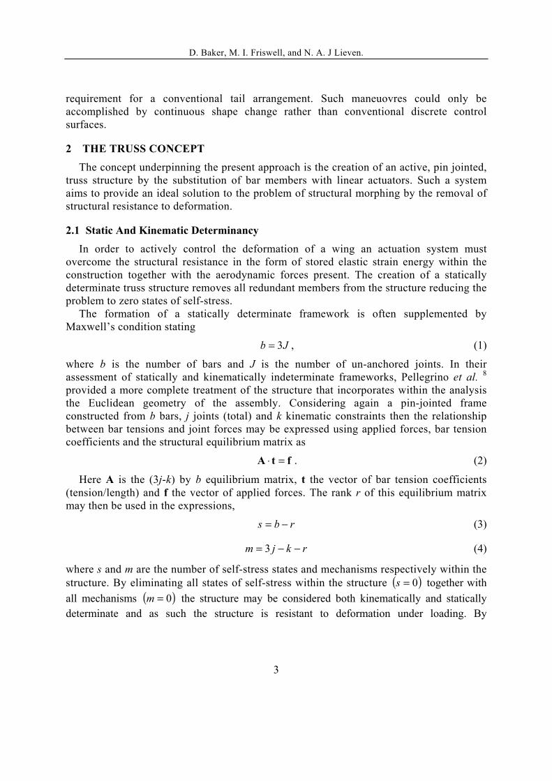
The Kagome truss pattern is displayed in two and three-dimensional forms in Figure 1. In the case of the three-dimensional manifestation two forms are possible, a Kagome plane with solid face sheet and two Kagome face sheets connected by a double tetragonal pattern core.
a) b)
Figure 1: Two and three-dimensional manifestations of the Kagome truss pattern with double tetragonal core
Investigation of the application of Kagome structures for actuation9 concluded that the single Kagome plate with solid face sheet may be deformed via truss actuation to form any long wavelength deformation however practical limits of actuation energy limit formations to small Gaussian curvatures. In the case of the twin Kagome face structure it is suggested that no restriction is placed upon the Gaussian curvature of the desired form.
Consider a Kagome patterned structure consisting of 480 members (b) and 176 nodes (j) similar to that in Figure 1b. By restraining all joints located at 0=x ( 24=k ), using (3) and (4), the number of states of self-stress and mechanisms are,
8=s ,
32=m
The presence of kinematic indeterminacy ( )0≠m reveals inextensional mechanisms. In order to eliminate mechanisms further bars may be added in the form of perimeter members, as illustrated in Figure 2.

D. Baker, M. I. Friswell, and N. A. J Lieven.
5
Figure 2: Patched Kagome structure
Analysis of this structure with similar constraints reveals,
23=s ,
5=m
By removing mid-plane symmetry from the structure it is it is possible to create a statically and kinematically determinate structure10. This is achieved by displacement of the joints located at 0=y as depicted by Figure 4. Retention of the nodal constraints previously outlined yields,
18=s ,
0=m
However in keeping with the investigations of Symons et al.10 the structure is revealed to be both statically and kinematically determinate if the number of applied constraints is limited to 6=k in order to prevent rigid body motions.
Figure 3: Asymmetric Kagome Structure
D. Baker, M. I. Friswell, and N. A. J Lieven.
6
3 THE APPLICATION TO A MORPHING WING
Using a repeating network of the Kagome lattice structure with upper and lower nodes displaced to form the aerofoil a straight a wing geometry may be created incorporating an active truss section allowing active camber control by the substitution of selected truss members with linear actuators.
A model formulated within MATLAB is used to create and analyse the pin-jointed truss and is limited to linear, elastic behavior. In order to replicate the effects of an applied actuation force point forces are located at selected nodes with direction constrained to that of the selected member. In this manner the observed actuator stroke is analogous to the measured strain of the connecting member that remains in position throughout the analysis.
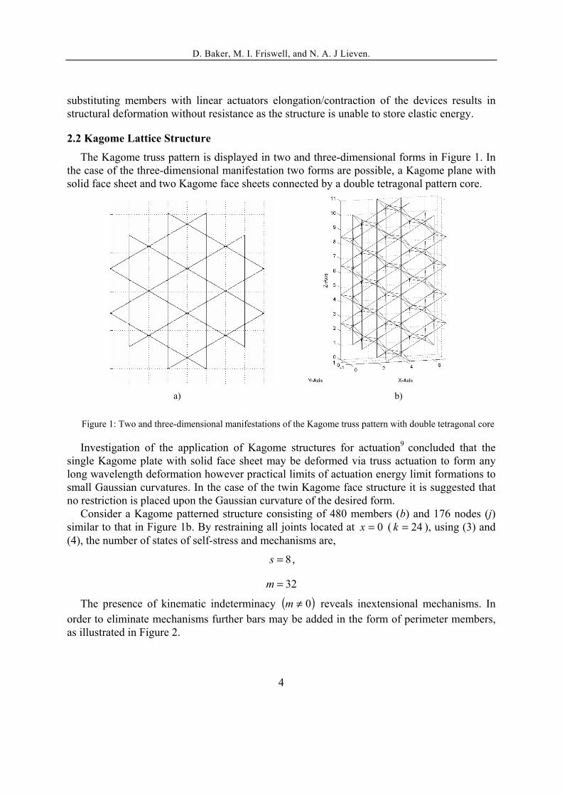
Considering a chord length of 1m, initial investigations assume 2-Dimensional flow and use of a Kagome truss structure to form a smooth variable camber aerofoil. XFOIL v.6.9411 was used to provide the aerodynamic analysis using a combination of inviscid panel solution coupled with a viscous boundary layer transition and envelope criterion taken from the ISES code. As a baseline aerofoil geometry the NACA 0012 profile is selected as depicted by Figure 4 together with resulting pressure distribution at 0˚ angle of attack, note the dashed line represents inviscid calculation and the solid line the considered viscous solution.
Figure 4: NACA 0012 pressure distribution at 0˚ AoA.
By extracting the pressure distribution from the calculated Cp a series of nodal loads is calculated for the upper and lower plates in order to replicate aerodynamic forces. The application of a series of simulated actuation forces on selected upper plate members coupled with forces of opposing direction and equal magnitude placed upon the reflected lower face nodes induces bending of the structure.
The revised pressure distribution is then calculated using XFOIL and updated nodal forces applied in order to evaluate the deflection due to the pressure imbalance on the upper and lower surfaces, an iterative process terminated as deformation converges.
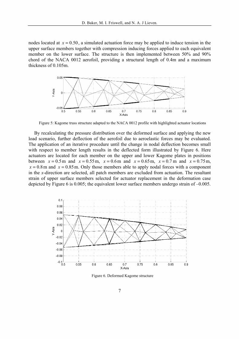
Figure 5 shows a structure consisting of 16 repeating unit cells with an additional 8 half-cells. Here the total number of nodes is 176, connected by 522 members. By restraining all
D. Baker, M. I. Friswell, and N. A. J Lieven.
7
nodes located at 50.0=x , a simulated actuation force may be applied to induce tension in the upper surface members together with compression inducing forces applied to each equivalent member on the lower surface. The structure is then implemented between 50% and 90% chord of the NACA 0012 aerofoil, providing a structural length of 0.4m and a maximum thickness of 0.105m.
Figure 5: Kagome truss structure adapted to the NACA 0012 profile with highlighted actuator locations
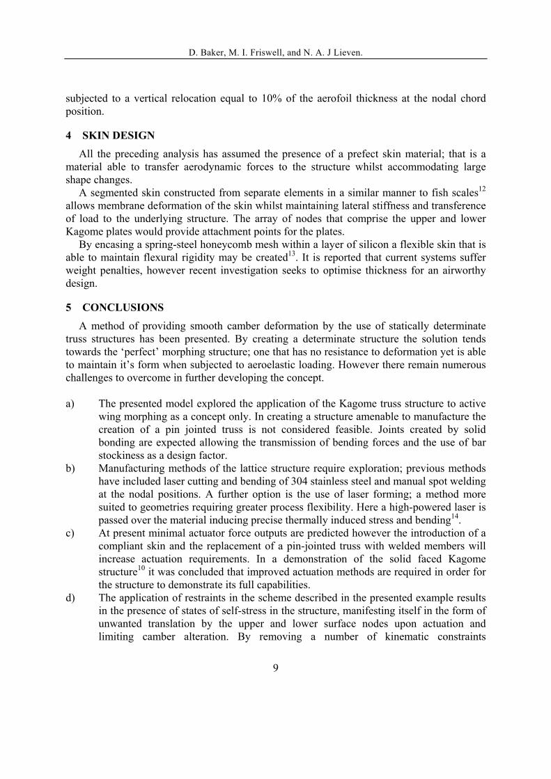
By recalculating the pressure distribution over the deformed surface and applying the new load scenario, further deflection of the aerofoil due to aeroelastic forces may be evaluated. The application of an iterative procedure until the change in nodal deflection becomes small with respect to member length results in the deflected form illustrated by Figure 6. Here actuators are located for each member on the upper and lower Kagome plates in positions between 5.0=x m and 55.0=x m, 6.0=x m and 65.0=x m, 7.0=x m and 75.0=x m,
8.0=x m and 85.0=x m. Only those members able to apply nodal forces with a component in the x-direction are selected, all patch members are excluded from actuation. The resultant strain of upper surface members selected for actuator replacement in the deformation case depicted by Figure 6 is 0.005; the equivalent lower surface members undergo strain of –0.005.
Figure 6. Deformed Kagome structure

D. Baker, M. I. Friswell, and N. A. J Lieven.
8
The resulting change in aerofoil profile exhibits the pressure distribution displayed in Figure 7.
Figure 7. Pressure distribution for the deformed aerofoil at 0˚ AoA
Curvature of the deformed geometry may be further increased by the application of actuation forces to an increased number of members and by an increase in the applied actuation force. Figure 8 reveals the result of providing simulated actuation forces in a similar scheme to that of Figure 5 however in this case all upper and lower face members with x-component direction are selected for substitution as actuators. The simulated actuator force is increased to provide an actuated member strain for upper and lower surfaces of 0.18 and –0.18 respectively.
Figure 8. Demonstrated deformation with increased simulated actuation force together with increased actuator distribution.
In order to limit undesired vertical displacement of the upper and lower surface nodes when subjected to actuation forces the degree of asymmetry (ref. Figure 3) of the structure was increased. For the example given by Figure 8, nodes lying on the central plane are
D. Baker, M. I. Friswell, and N. A. J Lieven.
9
subjected to a vertical relocation equal to 10% of the aerofoil thickness at the nodal chord position.
4 SKIN DESIGN
All the preceding analysis has assumed the presence of a prefect skin material; that is a material able to transfer aerodynamic forces to the structure whilst accommodating large shape changes.
A segmented skin constructed from separate elements in a similar manner to fish scales12 allows membrane deformation of the skin whilst maintaining lateral stiffness and transference of load to the underlying structure. The array of nodes that comprise the upper and lower Kagome plates would provide attachment points for the plates.
By encasing a spring-steel honeycomb mesh within a layer of silicon a flexible skin that is able to maintain flexural rigidity may be created13. It is reported that current systems suffer weight penalties, however recent investigation seeks to optimise thickness for an airworthy design.
5 CONCLUSIONS
A method of providing smooth camber deformation by the use of statically determinate truss structures has been presented. By creating a determinate structure the solution tends towards the ‘perfect’ morphing structure; one that has no resistance to deformation yet is able to maintain it’s form when subjected to aeroelastic loading. However there remain numerous challenges to overcome in further developing the concept.
a) The presented model explored the application of the Kagome truss structure to active
wing morphing as a concept only. In creating a structure amenable to manufacture the creation of a pin jointed truss is not considered feasible. Joints created by solid bonding are expected allowing the transmission of bending forces and the use of bar stockiness as a design factor.
b) Manufacturing methods of the lattice structure require exploration; previous methods have included laser cutting and bending of 304 stainless steel and manual spot welding at the nodal positions. A further option is the use of laser forming; a method more suited to geometries requiring greater process flexibility. Here a high-powered laser is passed over the material inducing precise thermally induced stress and bending14.
c) At present minimal actuator force outputs are predicted however the introduction of a compliant skin and the replacement of a pin-jointed truss with welded members will increase actuation requirements. In a demonstration of the solid faced Kagome structure10 it was concluded that improved actuation methods are required in order for the structure to demonstrate its full capabilities.
d) The application of restraints in the scheme described in the presented example results in the presence of states of self-stress in the structure, manifesting itself in the form of unwanted translation by the upper and lower surface nodes upon actuation and limiting camber alteration. By removing a number of kinematic constraints

D. Baker, M. I. Friswell, and N. A. J Lieven.
10
determinacy is achievable. In addition to this spanwise variation of the truss geometry is permitted.
ACKNOWLEDGMENTS
The authors acknowledge the support of the European Commission through the Marie Currie Excellence Grant MEXT-CT-2003-002690 and of the EPSRC (studentship: D. Baker).
REFERENCES
[1] A.K. Jha and J.N. Kudva, “Morphing aircraft concepts, classifications, and challenges”, Proceedings of SPIE –Smart Structures and Materials, 5388, 213-224 (2004).
[2] J. Szodruch and R. Hilbig, “Variable wing camber for transport aircraft”, Progress in Aerospace Sciences, 25, 297-328 (1988).
[3] B. Sanders, F.E. Eastep and E. Forster, “Aerodynamic and aeroelastic characteristics of wings with conformal control surfaces for morphing aircraft”, Journal of Aircraft, 40, 94-99 (2003).
[4] A. Bolonkin and G.B. Gilyard, “Estimated benefits of variable-geometry wing camber control for transport aircraft”, NASA Technical Memorandum, NASA/TM-206586 (1999).
[5] J.N. Kudva, C.A. Martin, L.B. Scherer, A.P. Jardine, A.R. McGowan, R.C. Lake, G. Sendeckyj and B. Sanders, “Overview of the DARPA/AFRL/NASA Smart Wing
program”, Proceedings of SPIE –Smart Structures and Materials, 3674, 230-236 (1999). [6] D.E. Gevers, “Multipurpose aircraft”, US Patent, US 5’850’990. [7] A.R. McGowan, D.E. Cox, B.S. Lazos, M.R. Waszak, D.L. Raney, E.J. Siochi and S. Paul Pao, “Biologically-inspired techmologies in NASA’s morphing project”,
Proceedings of SPIE –Smart Structures and Materials, 5051, 1-13 (2003). [8] S. Pellegrino and A. R. Calladine, “Matrix analysis of statically and kinematically
indeterminate frameworks”, International Journal of Solids and Structures, 22, 409-428 (1986).
[9] R.G. Hutchinson, N. Wicks, A.G. Evans, N.A. Fleck and J.W. Hutchinson, “Kagome plate structures for actuation”, International Journal of Solids and Structures, 40, 6969-6980 (2003).
[10] D.D. Symons, R.G. Hutchinson and N.A. Fleck, “Actuation of the Kagome Double-Layer Grid. Part 1: Prediction of performance of the perfect structure, “Journal of the Mechanics and Physics of Solids”, In Press.
[11] M. Drela, “XFOIL 6.94 User Guide” http://raphael.mit.edu/xfoil (last accessed 01/05/05). [12] O.K. Rediniotis, L.N. Wilson, D.C. Lagoudas and M.M. Khan, “Development of a shape
memory alloy actuated biomimetic hydrofoil”, Journal of Intelligent Material Systems and Structures, 13, 35-49 (2002).
[13] D.S. Ramrkahyani, G. A. Lesieutre, M. Frecker and S. Bharti, “Aircraft structural morphing using tendon actuated compliant cellular trusses”,

D. Baker, M. I. Friswell, and N. A. J Lieven.
11
AIAA/ASME/ASCE/AHS/ASC Structures, Structural Dynamics & MaterialsConference, (2004).
[14]M. Geiger, M. Merklein and M. Pitz, “Laser and forming technology – an idea and the way of implementation”, Journal of Materials Processing Technology, 151, 3-11 (2004).