Embed Size (px)
Citation preview
Fundamentals of RE
Chapter 4
Requirements Specification& Documentation
start
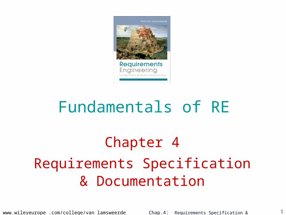
Chap. 2:Elicitationtechniques
Chap. 3:Evaluationtechniques
alternative options
agreedrequirements
documented requirements
consolidatedrequirements
Chap. 4: Specification &documentationtechniques
Chap.1: RE products and processes
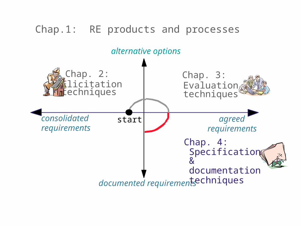
Specification & documentation: as introduced in Chapter 1 ...
Precise definition of all features of the agreed system– Objectives, concepts, relevant domain properties,
system/software requirements, assumptions, responsibilities
– Rationale for options taken, satisfaction arguments
– Likely system evolutions & variants
Organization of these in a coherent structure
Documentation in a form understandable by all parties– Often in annex: costs, workplan, delivery schedules
Resulting product: Requirements Document (RD)
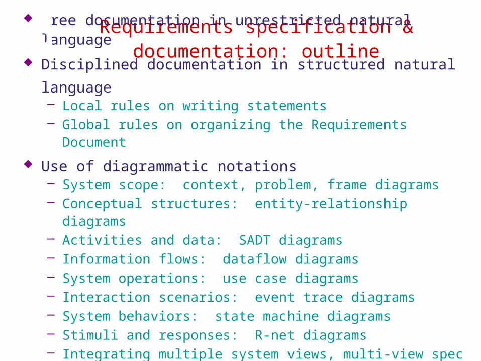
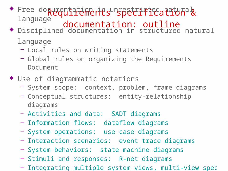
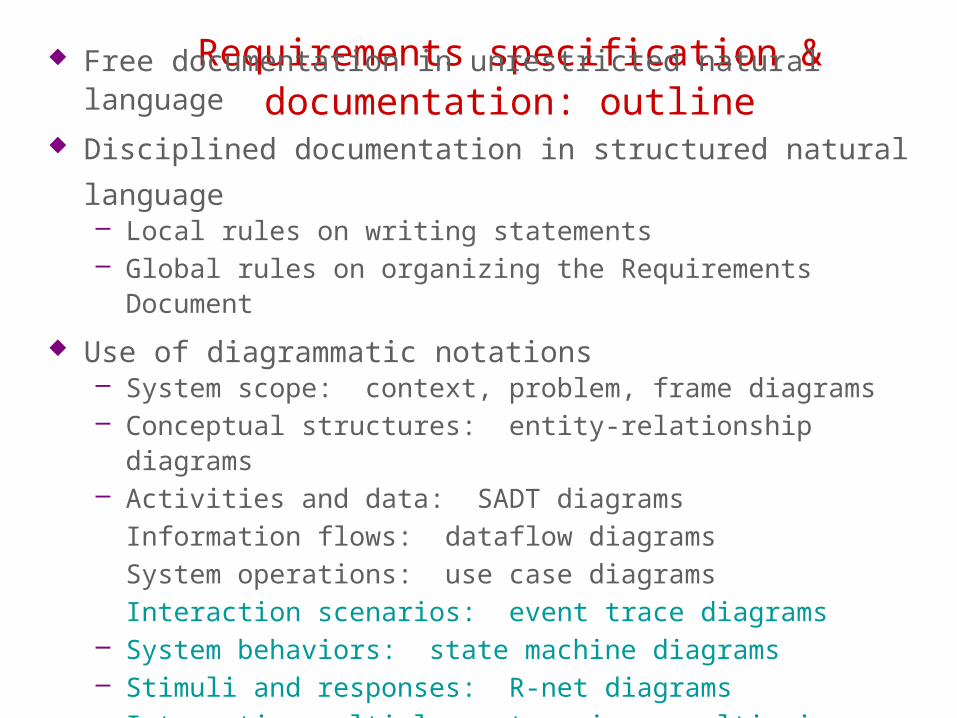
Requirements specification & documentation: outline
Free documentation in unrestricted natural language
Disciplined documentation in structured natural language– Local rules on writing statements– Global rules on organizing the Requirements Document
Use of diagrammatic notations– System scope: context, problem, frame diagrams– Conceptual structures: entity-relationship diagrams– Activities and data: SADT diagrams– Information flows: dataflow diagrams– System operations: use case diagrams– Interaction scenarios: event trace diagrams– System behaviors: state machine diagrams– Stimuli and responses: R-net diagrams– Integrating multiple system views, multi-view spec in UML
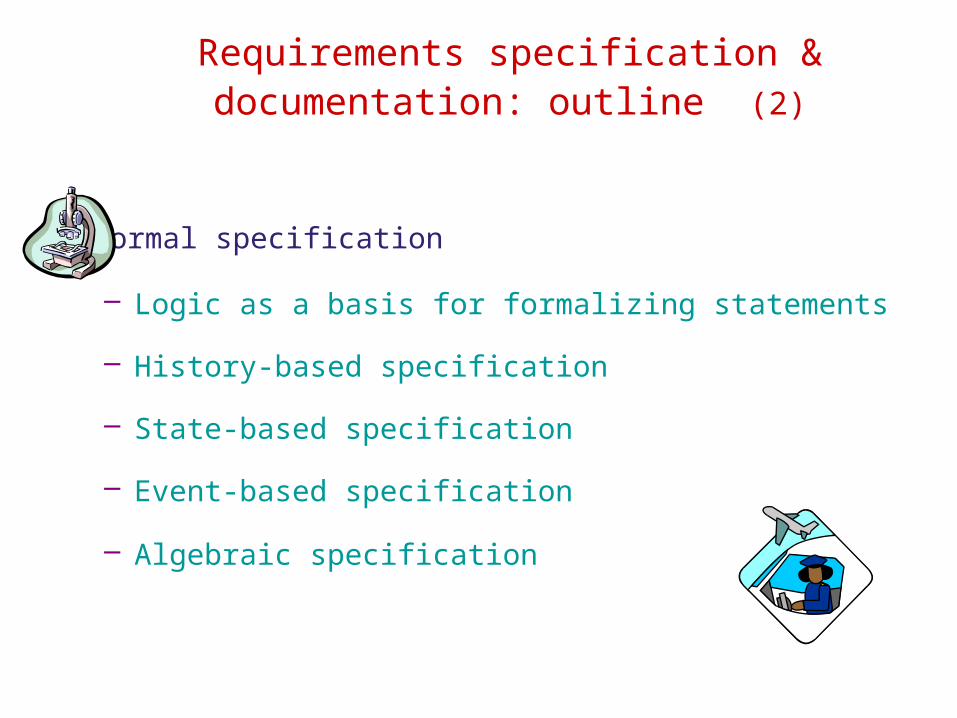
Requirements specification & documentation: outline (2)
Formal specification
– Logic as a basis for formalizing statements
– History-based specification
– State-based specification
– Event-based specification
– Algebraic specification
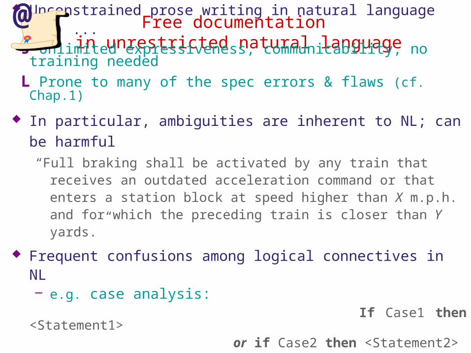
Free documentation in unrestricted natural language
Unconstrained prose writing in natural language (NL) ... J Unlimited expressiveness, communicability, no training
needed L Prone to many of the spec errors & flaws (cf. Chap.1)
In particular, ambiguities are inherent to NL; can be harmful“Full braking shall be activated by any train that receives an outdated
acceleration command or that enters a station block at speed higher than X m.p.h. and for which the preceding train is closer than Y yards.”
Frequent confusions among logical connectives in NL – e.g. case analysis:
If Case1 then <Statement1> or if Case2 then <Statement2> (amounts to true!)
vs. If Case1 then <Statement1> and if Case2 then <Statement2>
@
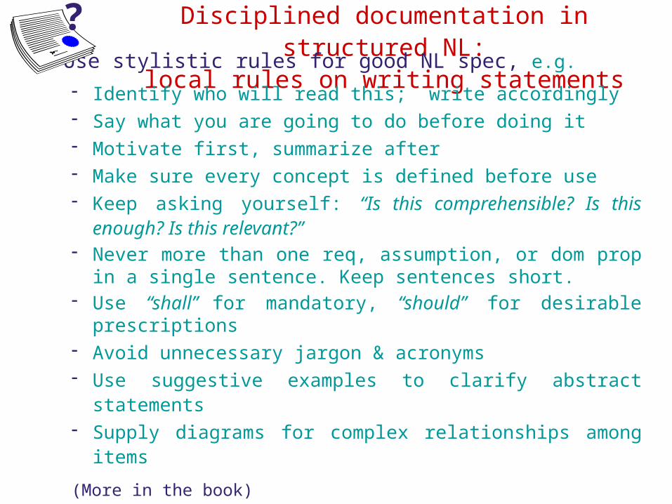
Disciplined documentation in structured NL:
local rules on writing statements Use stylistic rules for good NL spec, e.g.
- Identify who will read this; write accordingly- Say what you are going to do before doing it- Motivate first, summarize after- Make sure every concept is defined before use- Keep asking yourself: “Is this comprehensible? Is this
enough? Is this relevant?”- Never more than one req, assumption, or dom prop in a
single sentence. Keep sentences short.- Use “shall” for mandatory, “should” for desirable
prescriptions- Avoid unnecessary jargon & acronyms- Use suggestive examples to clarify abstract statements- Supply diagrams for complex relationships among items
(More in the book)
?
Disciplined documentation in structured NL:
local rules on writing statements (2)
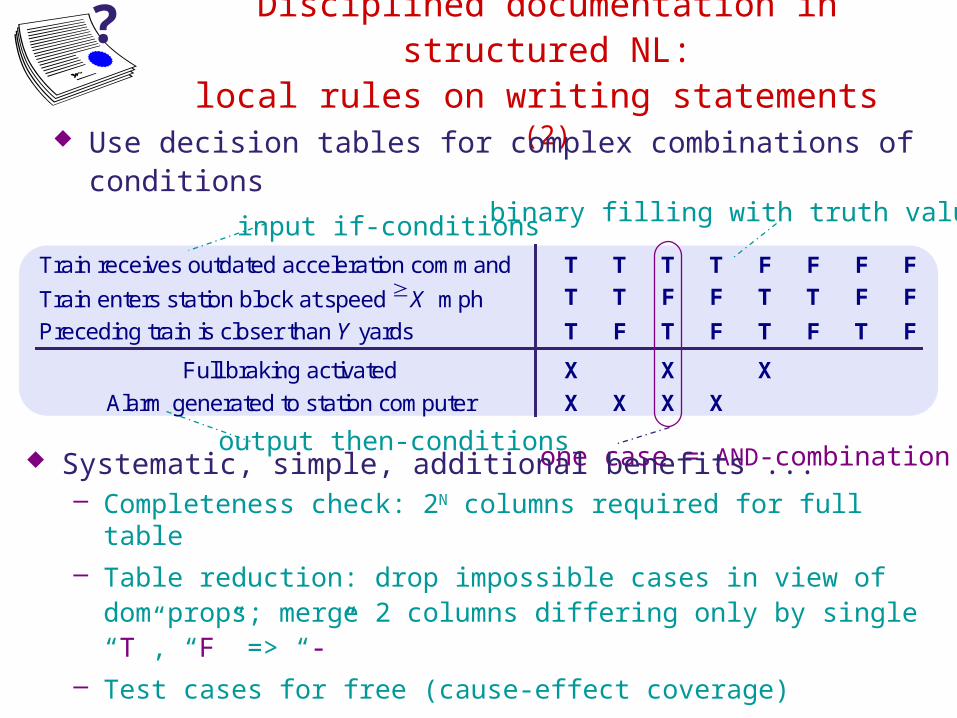
Use decision tables for complex combinations of conditions
Train receives outdated acceleration command T T T T F F F F
Train enters station block at speed X mph T T F F T T F F
Preceding train is closer than Y yards T F T F T F T F
Full braking activated X X X
Alarm generated to station computer X X X X
input if-conditions
output then-conditions
binary filling with truth values
one case = AND-combination Systematic, simple, additional benefits ...
– Completeness check: 2N columns required for full table – Table reduction: drop impossible cases in view of dom props;
merge 2 columns differing only by single “T”, “F” => “-”– Test cases for free (cause-effect coverage)
?
Disciplined documentation in structured NL:
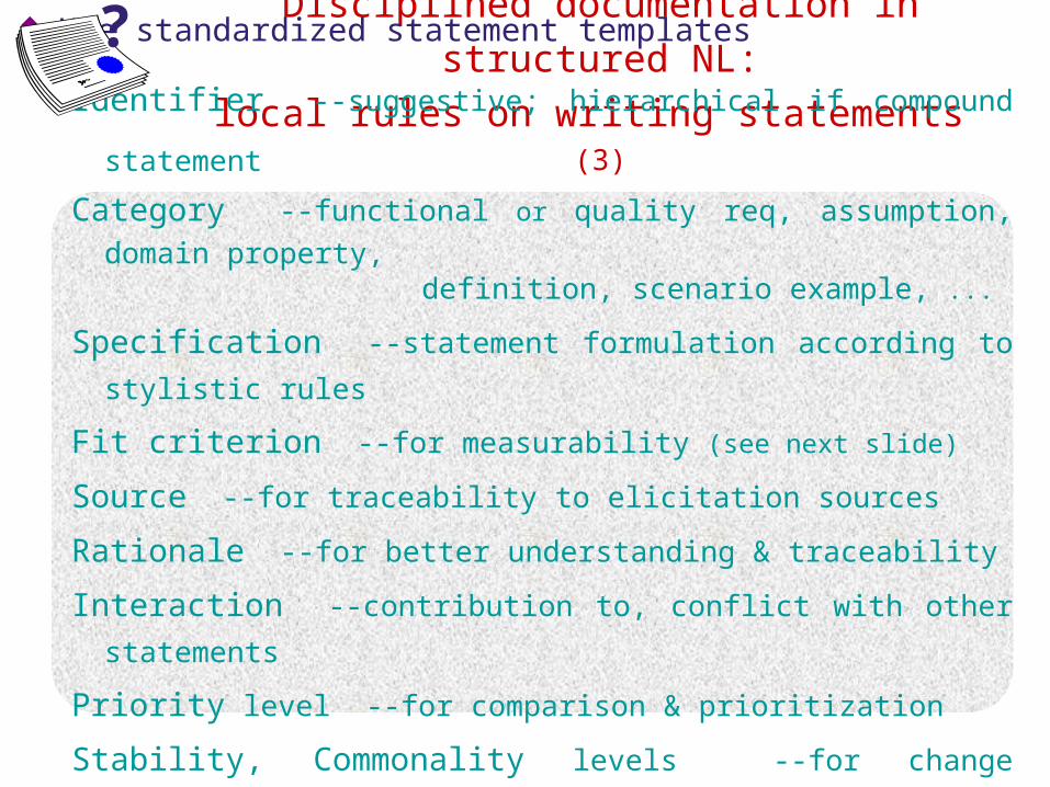
local rules on writing statements (3) Use standardized statement templates
Identifier --suggestive; hierarchical if compound statement
Category --functional or quality req, assumption, domain
property, definition, scenario example, ...
Specification --statement formulation according to stylistic
rules
Fit criterion --for measurability (see next slide)
Source --for traceability to elicitation sources
Rationale --for better understanding & traceability
Interaction --contribution to, conflict with other statements
Priority level --for comparison & prioritization
Stability, Commonality levels --for change management
?
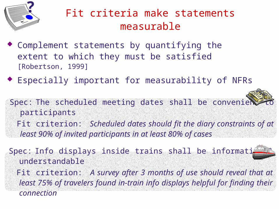
Fit criteria make statements measurable
Complement statements by quantifying the extent to which they must be satisfied [Robertson, 1999]
Especially important for measurability of NFRs
?
Spec: Info displays inside trains shall be informative & understandable
Fit criterion: A survey after 3 months of use should reveal that at least 75% of travelers found in-train info displays helpful for finding their connection
Spec: The scheduled meeting dates shall be convenient to participants
Fit criterion: Scheduled dates should fit the diary constraints of at least 90% of invited participants in at least 80% of cases
Disciplined documentation in structured
NL:
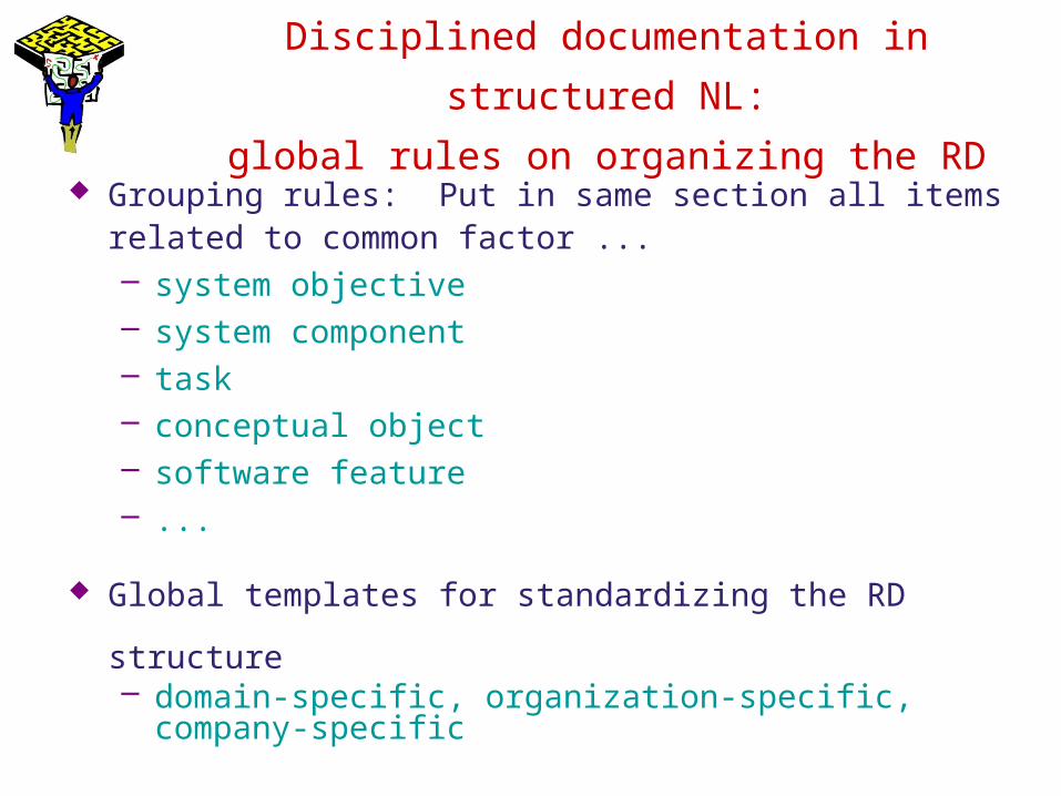
global rules on organizing the RD
Grouping rules: Put in same section all items related to common factor ...– system objective– system component– task– conceptual object– software feature– ...
Global templates for standardizing the RD structure– domain-specific, organization-specific, company-
specific
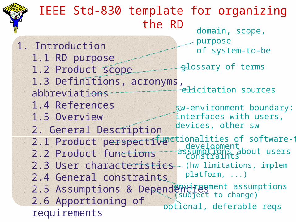
IEEE Std-830 template for organizing the RD
1. Introduction1.1 RD purpose1.2 Product scope1.3 Definitions, acronyms, abbreviations1.4 References1.5 Overview2. General Description2.1 Product perspective2.2 Product functions2.3 User characteristics2.4 General constraints2.5 Assumptions & Dependencies2.6 Apportioning of requirements3. Specific Requirements
sw-environment boundary:interfaces with users, devices, other sw
glossary of terms
domain, scope, purposeof system-to-be
elicitation sources
functionalities of software-to-be
assumptions about users
development constraints(hw limitations, implem platform, ...)
environment assumptions(subject to change)
optional, deferable reqs
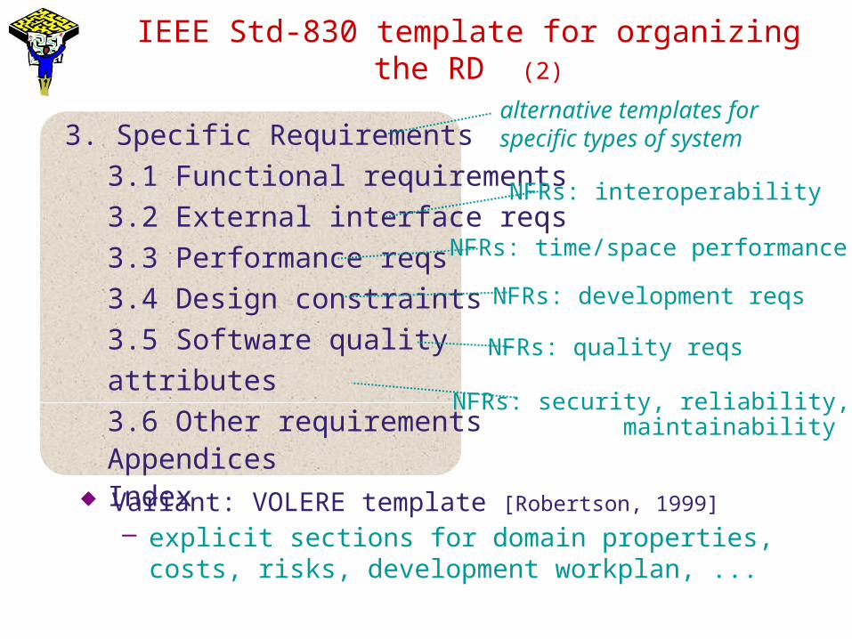
IEEE Std-830 template for organizing the RD (2)
3. Specific Requirements
3.1 Functional requirements3.2 External interface reqs3.3 Performance reqs3.4 Design constraints3.5 Software quality attributes3.6 Other requirementsAppendicesIndex
NFRs: development reqs
NFRs: interoperability
alternative templates for specific types of system
NFRs: time/space performance
NFRs: quality reqs
NFRs: security, reliability, maintainability
Variant: VOLERE template [Robertson, 1999]
– explicit sections for domain properties, costs, risks, development workplan, ...
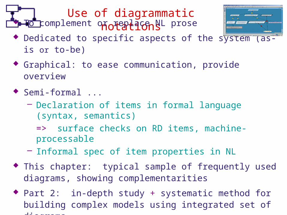
Use of diagrammatic notations
To complement or replace NL prose
Dedicated to specific aspects of the system (as-is or to-be)
Graphical: to ease communication, provide overview
Semi-formal ...– Declaration of items in formal language (syntax,
semantics) => surface checks on RD items, machine-processable
– Informal spec of item properties in NL
This chapter: typical sample of frequently used diagrams, showing complementarities
Part 2: in-depth study + systematic method for building complex models using integrated set of diagrams
Requirements specification & documentation: outline
Free documentation in unrestricted natural language
Disciplined documentation in structured natural language– Local rules on writing statements– Global rules on organizing the Requirements Document
Use of diagrammatic notations– System scope: context, problem, frame diagrams– Conceptual structures: entity-relationship diagrams– Activities and data: SADT diagrams– Information flows: dataflow diagrams– System operations: use case diagrams– Interaction scenarios: event trace diagrams– System behaviors: state machine diagrams– Stimuli and responses: R-net diagrams– Integrating multiple system views, multi-view spec in UML
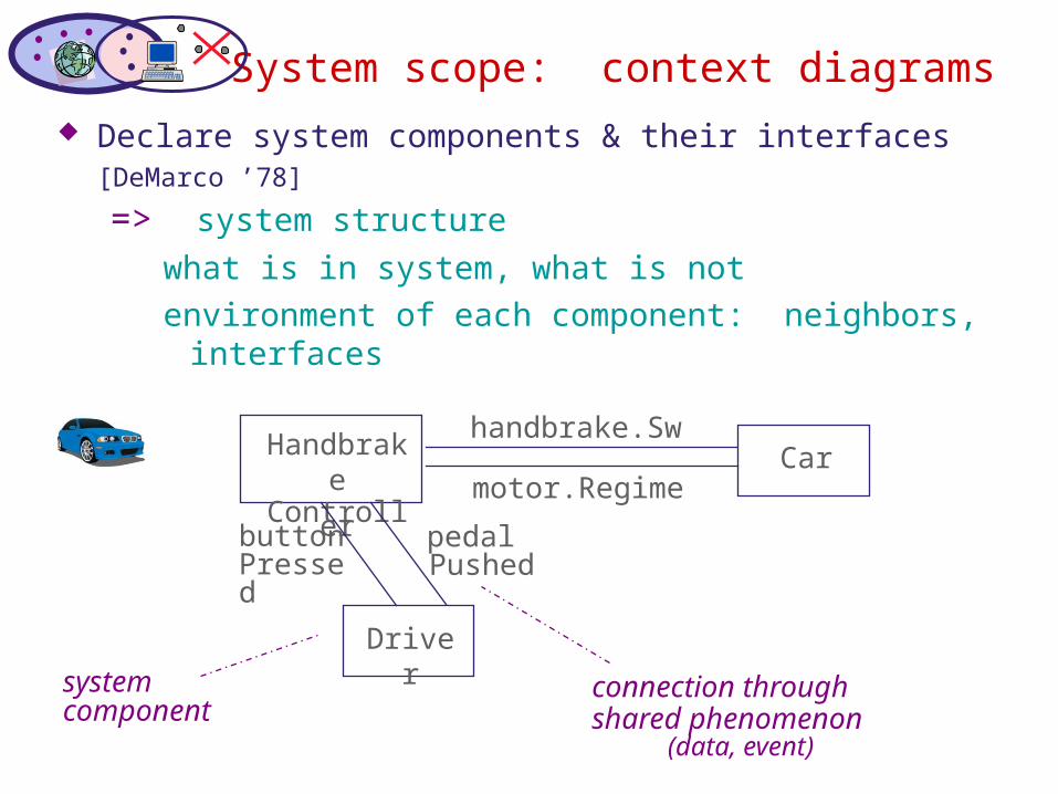
System scope: context diagrams
Declare system components & their interfaces [DeMarco ’78]
=> system structure
what is in system, what is notenvironment of each component: neighbors,
interfaces
HandbrakeController
Driver
Carhandbrake.Sw
motor.Regime
pedalPushed
buttonPressed
system component
connection throughshared
phenomenon(data, event)
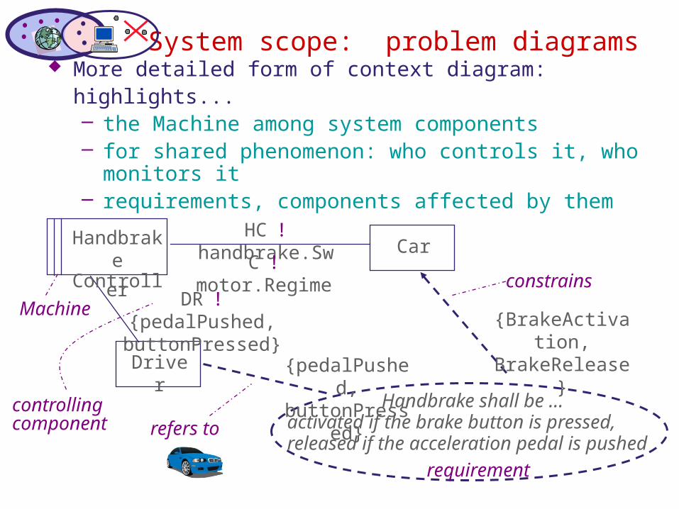
System scope: problem diagrams More detailed form of context diagram: highlights...
– the Machine among system components– for shared phenomenon: who controls it, who
monitors it– requirements, components affected by them
Driver
CarHC ! handbrake.Sw
C ! motor.Regime
DR ! {pedalPushed, buttonPressed}
Handbrake shall be ... activated if the brake button is pressed,released if the acceleration pedal is pushed
{pedalPushed, buttonPressed
}
{BrakeActivation, BrakeRelease}
controlling component
HandbrakeController
Machine
constrains
refers to
requirement
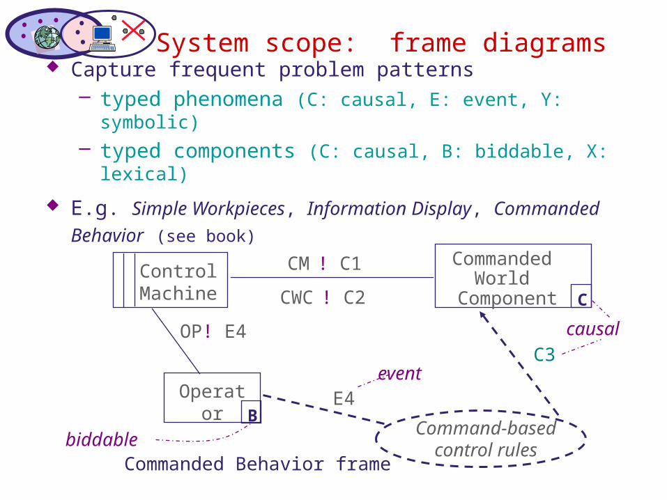
System scope: frame diagrams
Capture frequent problem patterns– typed phenomena (C: causal, E: event, Y: symbolic)– typed components (C: causal, B: biddable, X: lexical)
E.g. Simple Workpieces, Information Display, Commanded Behavior (see book)
Commanded Behavior frame
Control Machine
Operator
Commanded World
Component
CM ! C1
CWC ! C2
OP! E4
Command-basedcontrol rules
E4
C3
B
C
biddable
causal
event
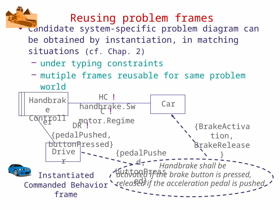
Reusing problem frames Candidate system-specific problem diagram can be
obtained by instantiation, in matching situations (cf. Chap. 2)– under typing constraints– mutiple frames reusable for same problem world
InstantiatedCommanded Behavior frame
Driver
CarHC ! handbrake.Sw
C ! motor.Regime
DR ! {pedalPushed, buttonPressed}
Handbrake shall be activated if the brake button is pressed,released if the acceleration pedal is pushed
{pedalPushed, buttonPressed
}
{BrakeActivation, BrakeRelease}
HandbrakeController
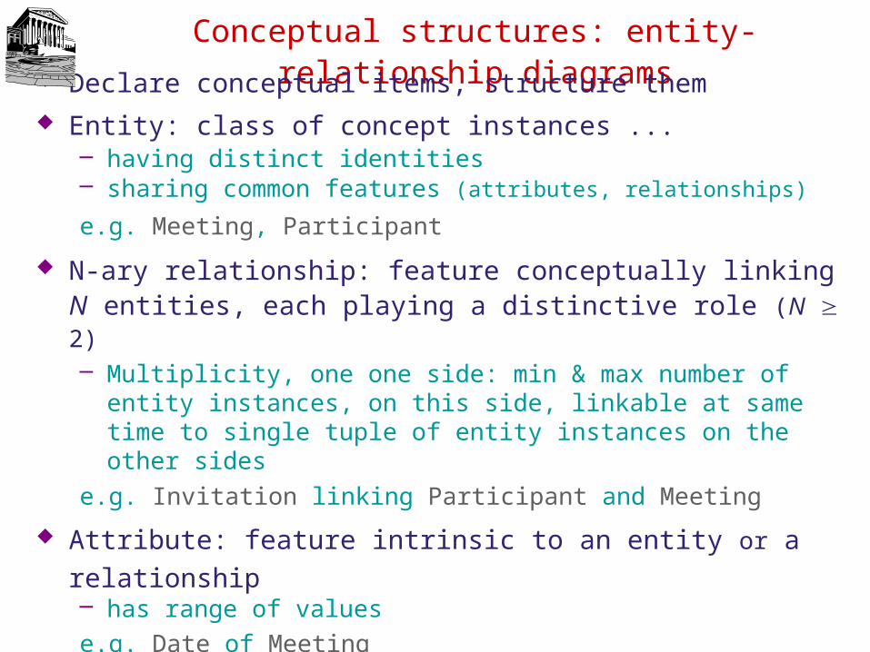
Conceptual structures: entity-relationship diagrams
Declare conceptual items, structure them Entity: class of concept instances ...
– having distinct identities– sharing common features (attributes, relationships)
e.g. Meeting, Participant
N-ary relationship: feature conceptually linking N entities, each playing a distinctive role (N ³ 2)– Multiplicity, one one side: min & max number of entity
instances, on this side, linkable at same time to single tuple of entity instances on the other sides
e.g. Invitation linking Participant and Meeting
Attribute: feature intrinsic to an entity or a relationship– has range of valuese.g. Date of Meeting
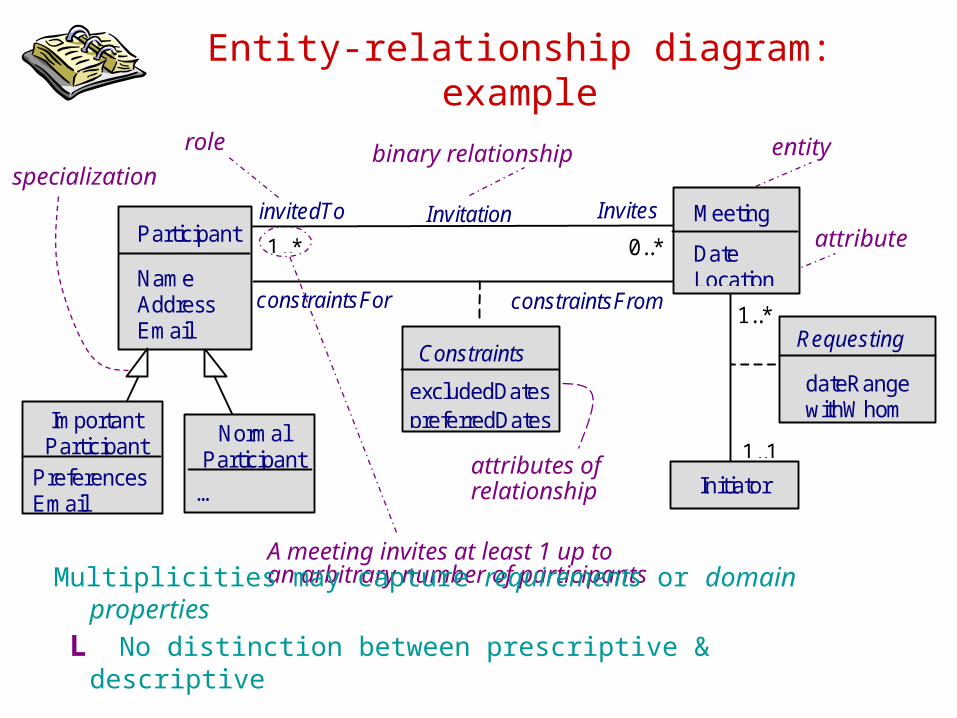
Entity-relationship diagram: example
Constraints
Participant1..* 0..*
Initiator
Invitation Meeting
Date Location
1..1
Name Address Email
InvitesinvitedTo
excludedDatespreferredDatesImportant
Participant Preferences Email
NormalParticipant
…
constraintsFor constraintsFrom
Requesting
dateRange withWhom
1..*
entity
attribute
attributes ofrelationship
binary relationship
A meeting invites at least 1 up toan arbitrary number of participants
rolespecializatio
n
Multiplicities may capture requirements or domain properties L No distinction between prescriptive & descriptive
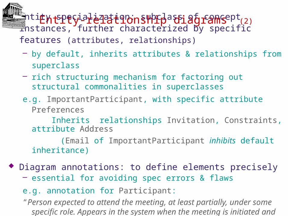
Entity-relationship diagrams (2)
Entity specialization: subclass of concept instances, further characterized by specific features (attributes, relationships)
– by default, inherits attributes & relationships from superclass– rich structuring mechanism for factoring out structural
commonalities in superclasses
e.g. ImportantParticipant, with specific attribute Preferences Inherits relationships Invitation, Constraints, attribute
Address
(Email of ImportantParticipant inhibits default inheritance)
Diagram annotations: to define elements precisely– essential for avoiding spec errors & flaws
e.g. annotation for Participant:“Person expected to attend the meeting, at least partially, under some
specific role. Appears in the system when the meeting is initiated and disappears when the meeting is no longer relevant to the system”
Requirements specification & documentation: outline
Free documentation in unrestricted natural language
Disciplined documentation in structured natural language– Local rules on writing statements– Global rules on organizing the Requirements Document
Use of diagrammatic notations– System scope: context, problem, frame diagrams– Conceptual structures: entity-relationship diagrams– Activities and data: SADT diagrams– Information flows: dataflow diagrams– System operations: use case diagrams– Interaction scenarios: event trace diagrams– System behaviors: state machine diagrams– Stimuli and responses: R-net diagrams– Integrating multiple system views, multi-view spec in UML
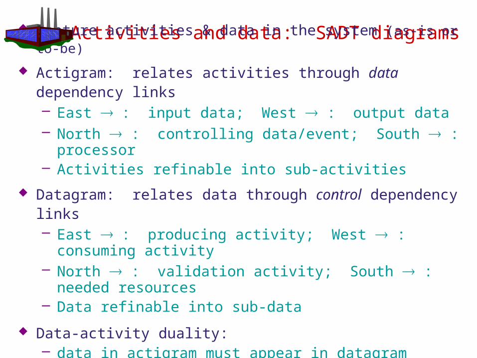
Activities and data: SADT diagrams
Capture activities & data in the system (as-is or to-be)
Actigram: relates activities through data dependency links– East ® : input data; West ® : output data– North ® : controlling data/event; South ® : processor– Activities refinable into sub-activities
Datagram: relates data through control dependency links– East ® : producing activity; West ® : consuming
activity– North ® : validation activity; South ® : needed
resources– Data refinable into sub-data
Data-activity duality:– data in actigram must appear in datagram – activities in datagram must appear in actigram
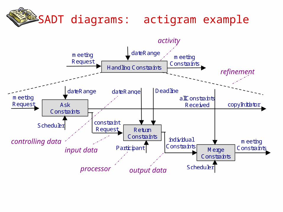
SADT diagrams: actigram example
meetingConstraints
Handling Constraints
AskConstraints
ReturnConstraints
meetingRequest
dateRange
dateRange
copyInitiator
constraintRequest
allConstraintsReceived
Scheduler
Participant MergeConstraints
dateRange DeadlinemeetingRequest
meetingConstraints
individualConstraints
Scheduler
refinement
input data
output dataprocessor
controlling data
activity
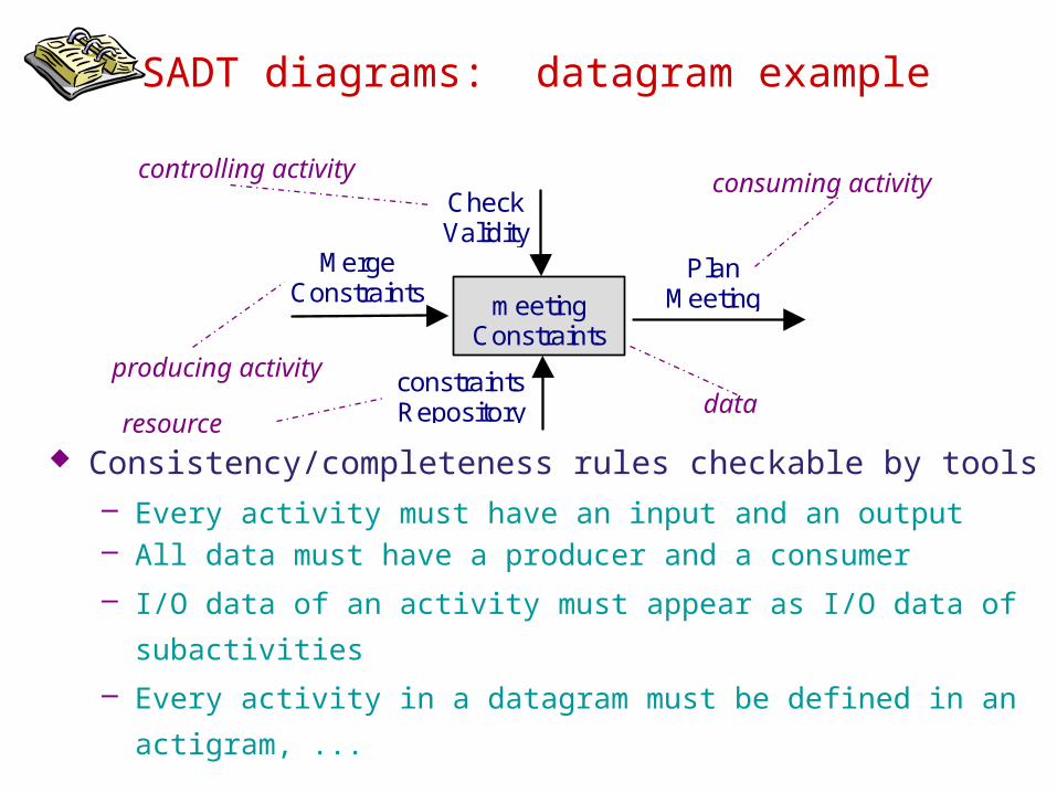
SADT diagrams: datagram example
MergeConstraints meeting
Constraints
constraintsRepository
CheckValidity
PlanMeeting
producing activity
controlling activity
consuming activity
resource
Consistency/completeness rules checkable by tools– Every activity must have an input and an output– All data must have a producer and a consumer
– I/O data of an activity must appear as I/O data of subactivities
– Every activity in a datagram must be defined in an
actigram, ...
data
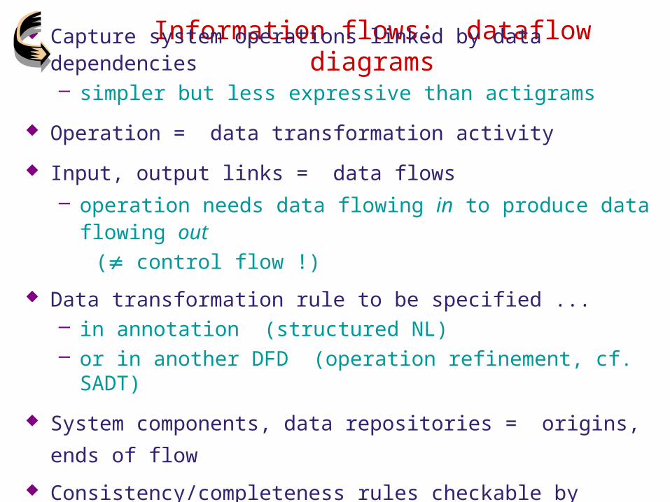
Information flows: dataflow diagrams Capture system operations linked by data dependencies
– simpler but less expressive than actigrams
Operation = data transformation activity
Input, output links = data flows– operation needs data flowing in to produce data
flowing out (¹ control flow !)
Data transformation rule to be specified ...– in annotation (structured NL) – or in another DFD (operation refinement, cf. SADT)
System components, data repositories = origins, ends of
flow
Consistency/completeness rules checkable by tools, cf. SADT
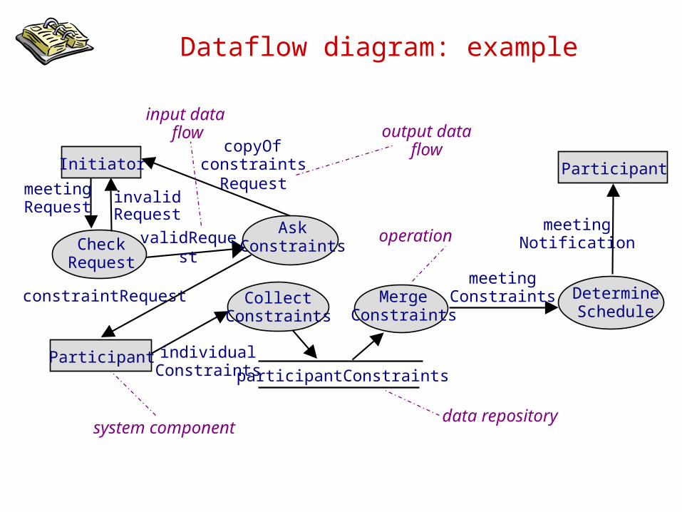
Dataflow diagram: example
Initiator
AskConstraints
copyOfconstraints
Request
constraintRequest
meetingRequest
meetingConstraints
individualConstraints
CollectConstraints
Participant
Participant
MergeConstraints
participantConstraints
DetermineSchedule
meetingNotificationCheck
Request
invalidRequest
validRequest operation
data repositorysystem
component
input data flow output data
flow

System operations: use case diagrams Capture operations to be performed by a system
component & interactions with other components
– yet simpler, outline view ... but vague
– to be made precise by annotations, interaction scenarios, ...
– introduced in UML to replace DFDs
Structuring mechanisms ...– <<include>>: to specify “suboperation”
– <<extend>> + precondition: to specify “variant” operation
in exception case
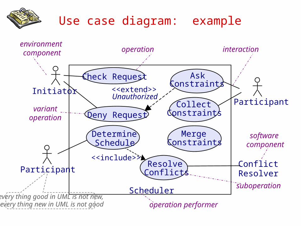
Use case diagram: example
DetermineSchedule
CollectConstraints
Scheduler
Check Request
Initiator
ConflictResolver
Participant
<<extend>>Unauthorized
<<include>>
Deny Request
AskConstraints
MergeConstraints
Resolve ConflictsParticipant
operation interactionenvironment component
software component
variantoperation
suboperationevery thing good in UML is not new, every thing new in UML is not good
operation performer
Requirements specification & documentation: outline
Free documentation in unrestricted natural language
Disciplined documentation in structured natural language– Local rules on writing statements– Global rules on organizing the Requirements Document
Use of diagrammatic notations– System scope: context, problem, frame diagrams– Conceptual structures: entity-relationship diagrams– Activities and data: SADT diagrams– Information flows: dataflow diagrams– System operations: use case diagrams– Interaction scenarios: event trace diagrams– System behaviors: state machine diagrams– Stimuli and responses: R-net diagrams– Integrating multiple system views, multi-view spec in UML
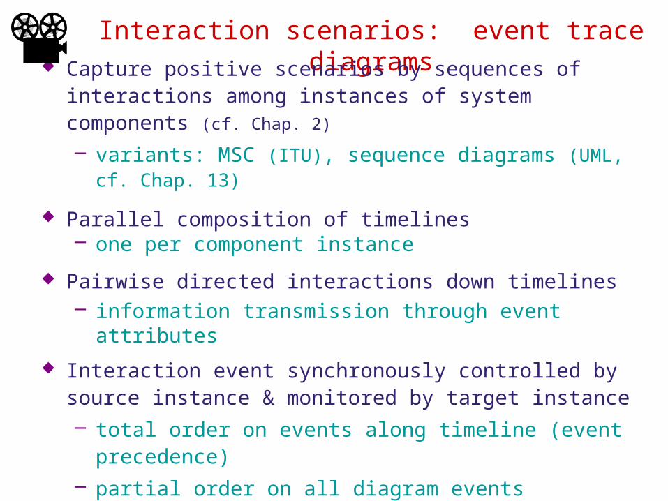
Interaction scenarios: event trace diagrams
Capture positive scenarios by sequences of interactions among instances of system components (cf. Chap. 2)
– variants: MSC (ITU), sequence diagrams (UML, cf. Chap. 13)
Parallel composition of timelines – one per component instance
Pairwise directed interactions down timelines– information transmission through event attributes
Interaction event synchronously controlled by source instance & monitored by target instance– total order on events along timeline (event
precedence)– partial order on all diagram events
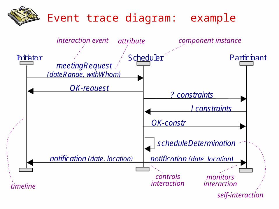
Event trace diagram: example
SchedulerInitiator ParticipantmeetingRequest
(dateRange, withWhom)
OK-request? constraints(dateRange)! constraints
OK-constr
scheduleDetermination
notification (date, location)notification (date, location)
interaction event attribute
component instance
controlsinteraction
monitorsinteraction
self-interactiontimeline
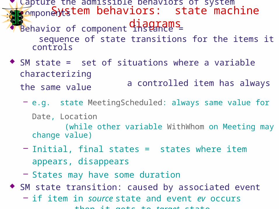
System behaviors: state machine diagrams
Capture the admissible behaviors of system components
Behavior of component instance = sequence of state transitions for the items it controls
SM state = set of situations where a variable characterizing
a controlled item has always the same value
– e.g. state MeetingScheduled: always same value for Date,
Location (while other variable WithWhom on Meeting may
change value)
– Initial, final states = states where item appears, disappears
– States may have some duration SM state transition: caused by associated event
– if item in source state and event ev occurs then it gets to target state– Events are instantaneous phenomena
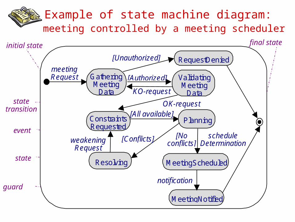
Example of state machine diagram: meeting controlled by a meeting scheduler
meetingRequest
OK-request
notification
[Noconflicts]
GatheringMeeting
Data
ConstraintsRequested
Planning
Resolving
MeetingNotified
[All available]
[Unauthorized]
[Conflicts]
RequestDenied
MeetingScheduled
weakeningRequest
scheduleDetermination
KO-request
ValidatingMeeting
Data
[Authorized]
initial state
final state
state
event
guard
statetransition
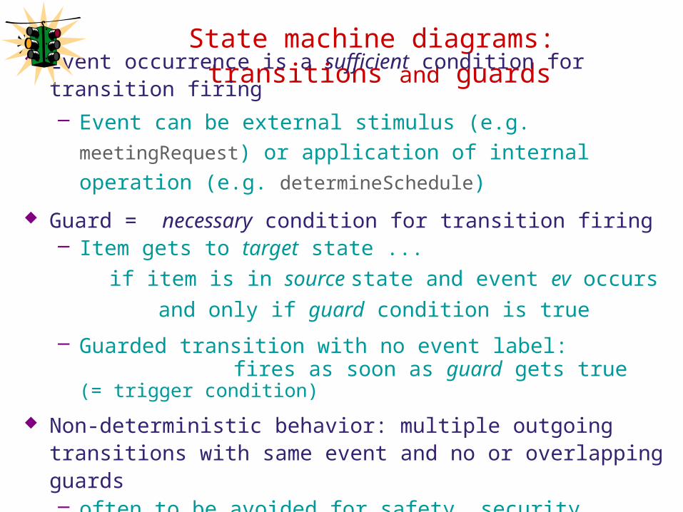
State machine diagrams: transitions and guards
Event occurrence is a sufficient condition for transition firing– Event can be external stimulus (e.g. meetingRequest) or
application of internal operation (e.g. determineSchedule)
Guard = necessary condition for transition firing– Item gets to target state ...
if item is in source state and event ev occurs
and only if guard condition is true
– Guarded transition with no event label: fires as soon as guard gets true (= trigger
condition)
Non-deterministic behavior: multiple outgoing transitions with same event and no or overlapping guards– often to be avoided for safety, security reasons
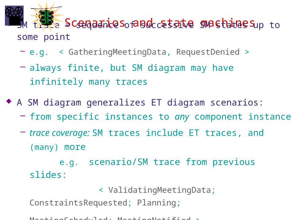
Scenarios and state machines SM trace = sequence of successive SM states up to some
point
– e.g. < GatheringMeetingData, RequestDenied >
– always finite, but SM diagram may have infinitely many
traces
A SM diagram generalizes ET diagram scenarios:– from specific instances to any component instance
– trace coverage: SM traces include ET traces, and (many)
more
e.g. scenario/SM trace from previous slides:
< ValidatingMeetingData; ConstraintsRequested;
Planning; MeetingScheduled; MeetingNotified
>
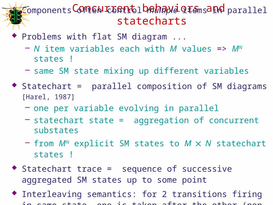
Concurrent behaviors and statecharts Components often control multiple items in parallel
Problems with flat SM diagram ...– N item variables each with M values => MN states !– same SM state mixing up different variables
Statechart = parallel composition of SM diagrams [Harel,
1987]
– one per variable evolving in parallel– statechart state = aggregation of concurrent substates– from MN explicit SM states to M ´ N statechart states !
Statechart trace = sequence of successive aggregated SM states up to some point
Interleaving semantics: for 2 transitions firing in same state, one is taken after the other (non-deterministic choice)
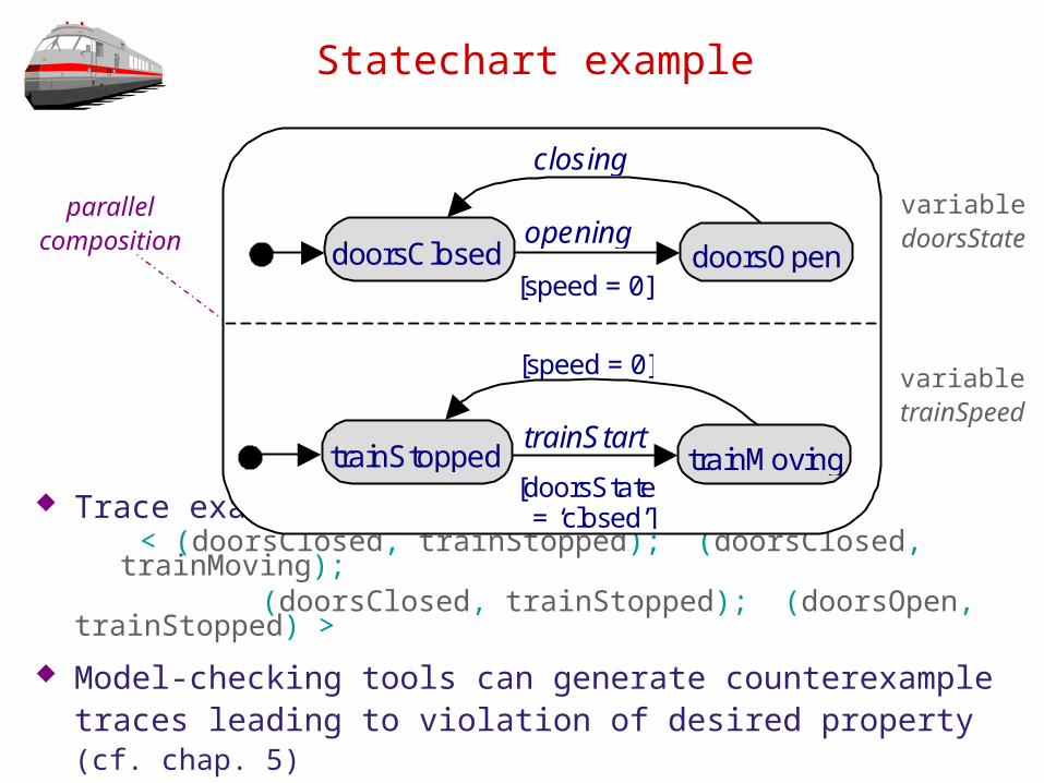
Statechart example
Trace example: < (doorsClosed, trainStopped); (doorsClosed, trainMoving);
(doorsClosed, trainStopped); (doorsOpen, trainStopped) >
Model-checking tools can generate counterexample traces leading to violation of desired property (cf. chap. 5)
doorsClosed doorsOpenopening
closing
[speed = 0]
trainStopped trainMovingtrainStart
[speed = 0]
[doorsState = ‘closed’]
parallelcompositio
n
variabledoorsState
variabletrainSpeed
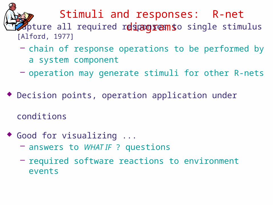
Stimuli and responses: R-net diagrams
Capture all required responses to single stimulus [Alford, 1977]
– chain of response operations to be performed by a system component
– operation may generate stimuli for other R-nets
Decision points, operation application under conditions
Good for visualizing ...– answers to WHAT IF ? questions
– required software reactions to environment events
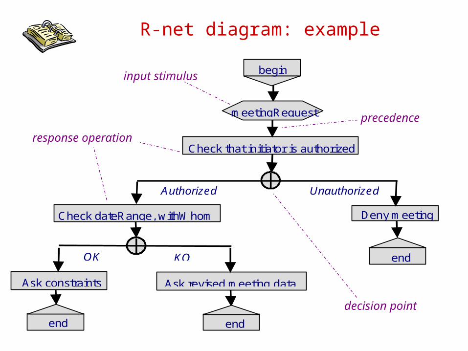
R-net diagram: example
Check that initiator is authorized
meetingRequest
begin
end
Check dateRange, withWhom
Ask revised meeting dataAsk constraints
Deny meeting
OK KO
end
end
Authorized Unauthorized
input stimulus
precedenceresponse operation
decision point
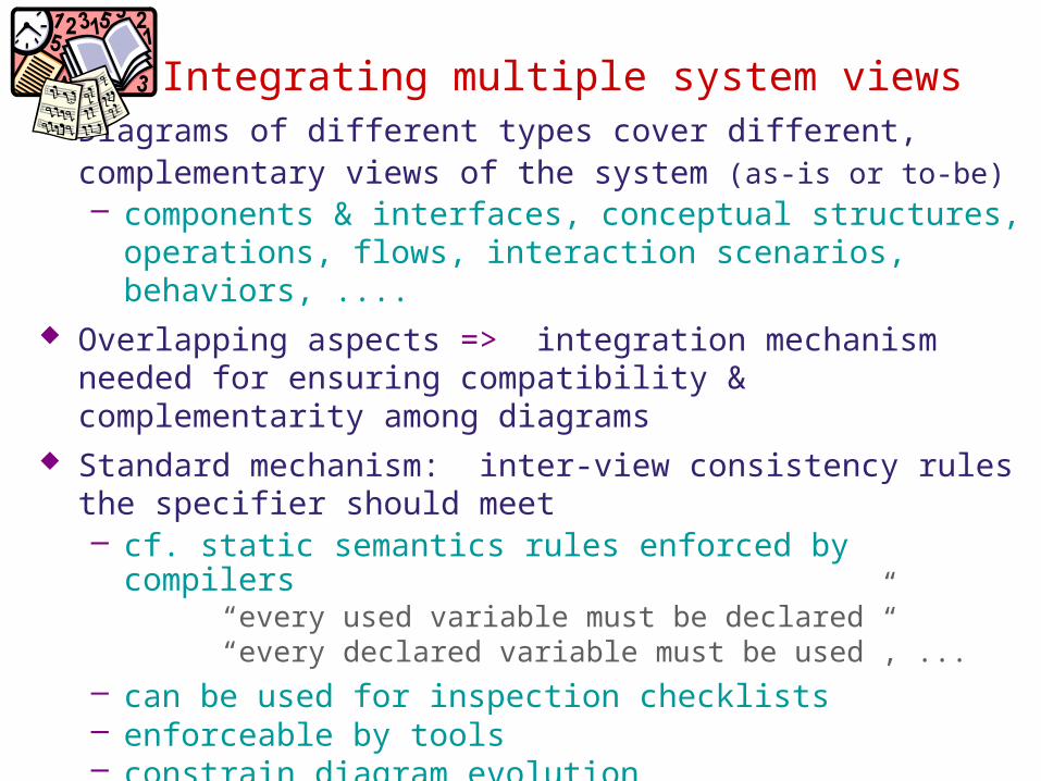
Integrating multiple system views
Diagrams of different types cover different, complementary views of the system (as-is or to-be)– components & interfaces, conceptual structures,
operations, flows, interaction scenarios, behaviors, .... Overlapping aspects => integration mechanism needed
for ensuring compatibility & complementarity among diagrams
Standard mechanism: inter-view consistency rules the specifier should meet– cf. static semantics rules enforced by compilers
“every used variable must be declared”“every declared variable must be used”, ...
– can be used for inspection checklists– enforceable by tools– constrain diagram evolution

Inter-view consistency rules: examples
Every component & interconnection in a problem diagram must be further specified in an ET diagram
Every shared phenomenon in a problem diagram must appear as event in an ET diagram or as entity, attribute, or relationship in an ER diagram
Every data in a flow or repository of a DFD diagram must be declared as entity, attribute, or relationship in an ER diagram
Every state in a SM diagram must correspond to some value for some attribute or relationship in an ER diagram
Every interaction event in an ET scenario must appear in a corresponding SM diagram
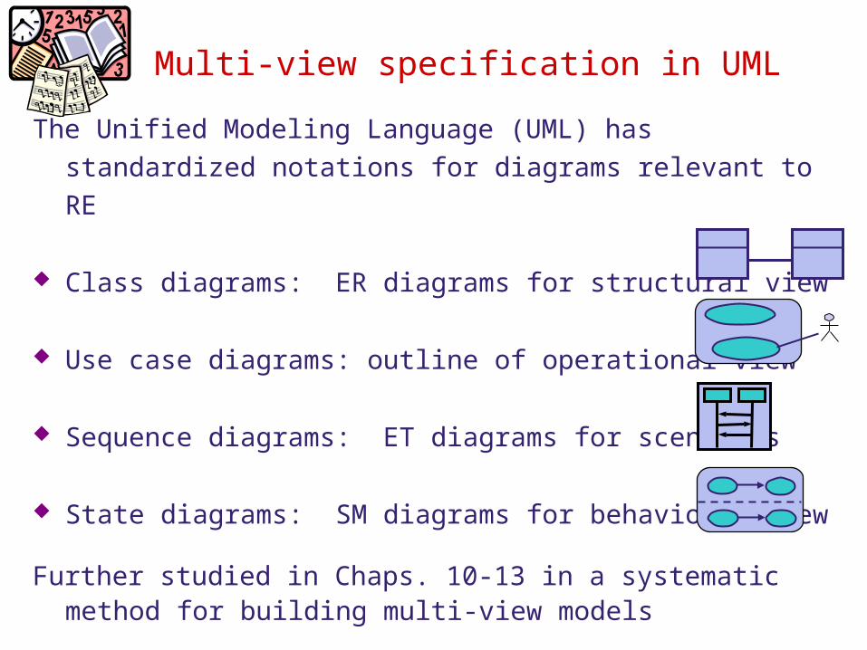
Multi-view specification in UML
The Unified Modeling Language (UML) has standardized notations for diagrams relevant to RE
Class diagrams: ER diagrams for structural view
Use case diagrams: outline of operational view
Sequence diagrams: ET diagrams for scenarios
State diagrams: SM diagrams for behavioral view
Further studied in Chaps. 10-13 in a systematic method for building multi-view models
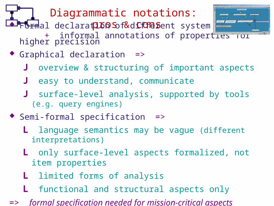
Diagrammatic notations: pros & cons Formal declaration of different system facets
+ informal annotations of properties for higher precision Graphical declaration =>
J overview & structuring of important aspects
J easy to understand, communicate
J surface-level analysis, supported by tools (e.g. query engines)
Semi-formal specification =>
L language semantics may be vague (different interpretations)
L only surface-level aspects formalized, not item properties
L limited forms of analysis
L functional and structural aspects only
=> formal specification needed for mission-critical aspects
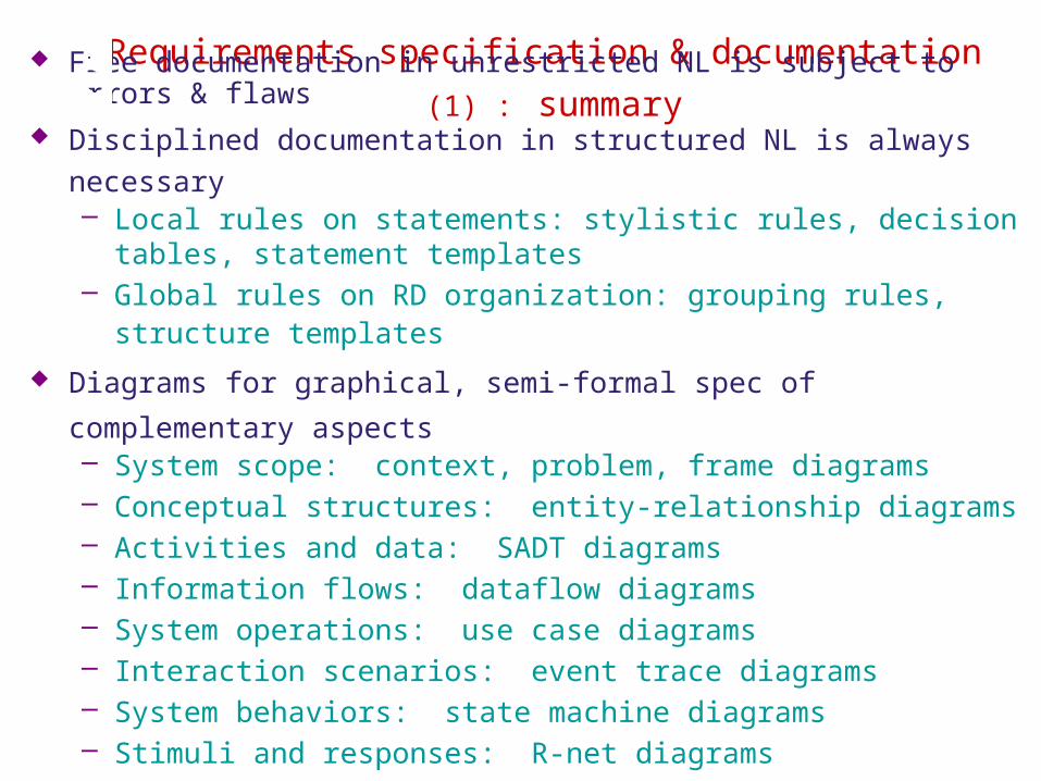
Requirements specification & documentation (1) : summary Free documentation in unrestricted NL is subject to errors & flaws
Disciplined documentation in structured NL is always necessary– Local rules on statements: stylistic rules, decision tables,
statement templates– Global rules on RD organization: grouping rules, structure
templates
Diagrams for graphical, semi-formal spec of complementary
aspects– System scope: context, problem, frame diagrams– Conceptual structures: entity-relationship diagrams– Activities and data: SADT diagrams– Information flows: dataflow diagrams– System operations: use case diagrams– Interaction scenarios: event trace diagrams– System behaviors: state machine diagrams– Stimuli and responses: R-net diagrams– Integrating multiple views, multi-view spec in UML


![Microsoft€¦ · Web view[MS-ASTASK]: ActiveSync Tasks Class Protocol Specification. Intellectual Property Rights Notice for Open Specifications Documentation. Technical Documentation](https://img.pdfslide.us/doc/110x75/60aad38b56a62905452957b6/microsoft-web-view-ms-astask-activesync-tasks-class-protocol-specification-intellectual.jpg)