Embed Size (px)
Citation preview
4/25/2019
1
Fundamentals of Produced Water Treatment in the Oil and
Gas Industry
Upstream O&G Subcommittee of Industrial Wastewater Committee (IWWC), WEF with
Produced Water Society (PWS)
1
2

4/25/2019
2
How to Participate Today
• Audio Modes
• Listen using Mic & Speakers
• Or, select “Use Telephone” and dial the conference (please remember long distance phone charges apply).
• Submit your questions using the Questions pane.
• A recording will be availablefor replay shortly after thiswebcast.
Today’s Moderator
Hossain Azam, Ph.D.Assistant Professor, Manhattan College
Email: [email protected]@gmail.com
Phone: 919-271-5347, 718-862-7854
3
4
4/25/2019
3
Presentation Outline with Speakers
Introduction to Produced Water Management
F. Morris Hoagland, P.E.
Jade Dragon, LLC
& Produced Water Society
Phone: 337-552-4215
Email: [email protected]
5
6
4/25/2019
4
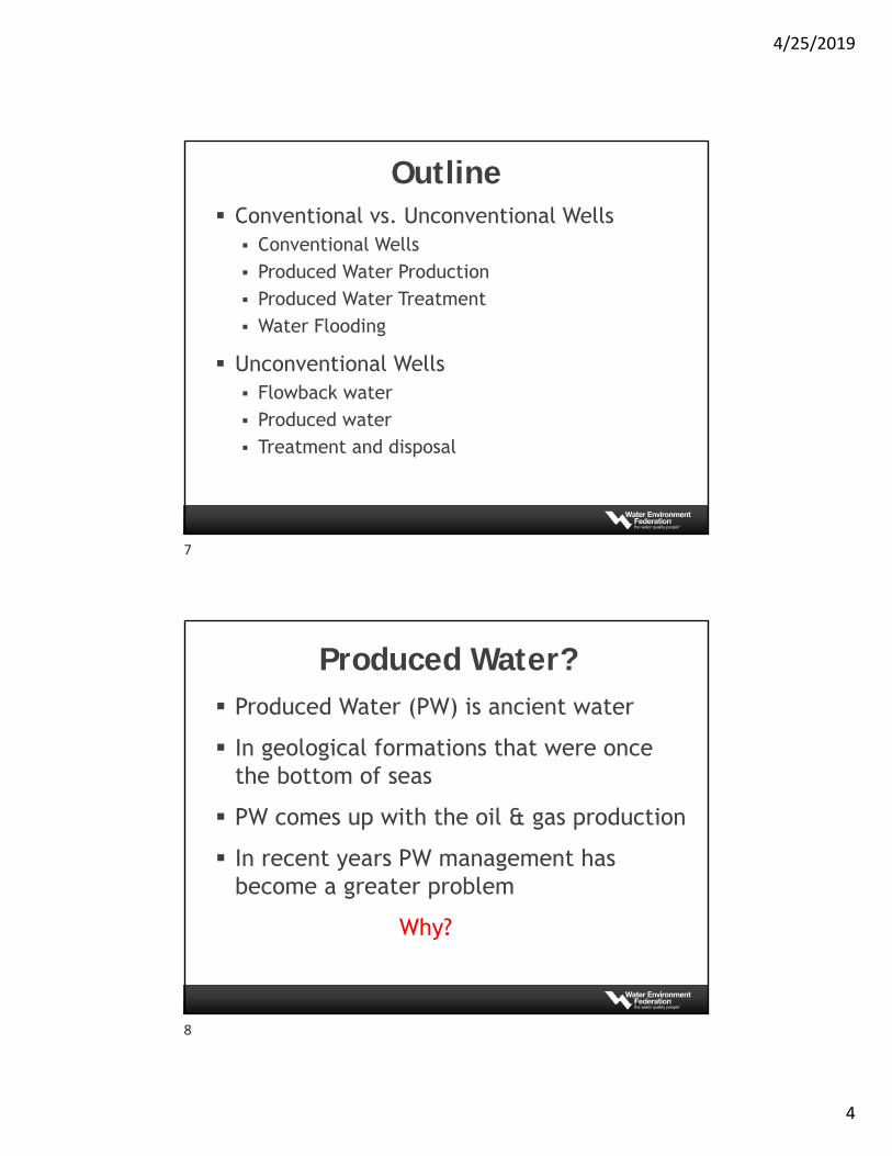
Outline Conventional vs. Unconventional Wells Conventional Wells Produced Water Production Produced Water Treatment Water Flooding
Unconventional Wells Flowback water Produced water Treatment and disposal
Produced Water? Produced Water (PW) is ancient water
In geological formations that were once the bottom of seas
PW comes up with the oil & gas production
In recent years PW management has become a greater problem
Why?
7
8
4/25/2019
5
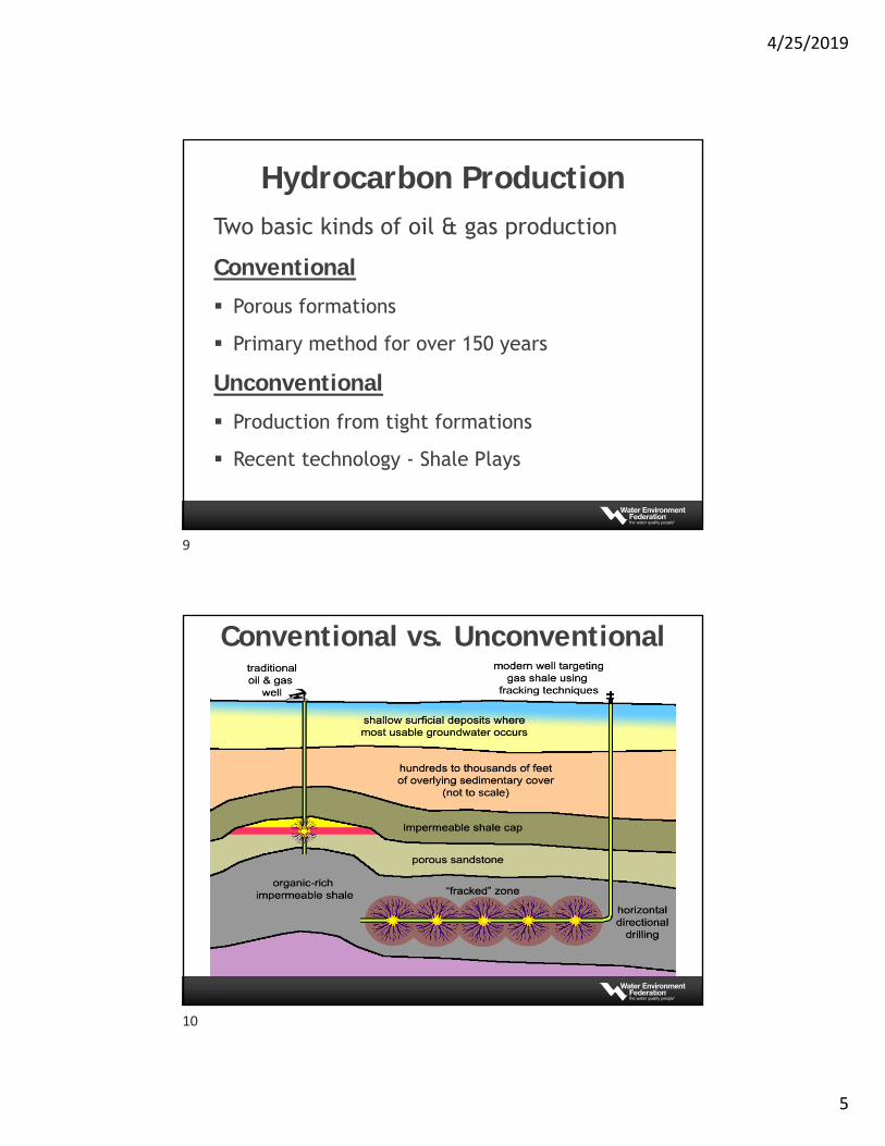
Hydrocarbon ProductionTwo basic kinds of oil & gas production
Conventional
Porous formations
Primary method for over 150 years
Unconventional
Production from tight formations
Recent technology - Shale Plays
Conventional vs. Unconventional
9
10
4/25/2019
6
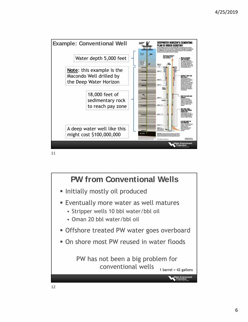
Example: Conventional Well
Water depth 5,000 feet
18,000 feet of sedimentary rock to reach pay zone
A deep water well like this might cost $100,000,000
Note: this example is the Macondo Well drilled by the Deep Water Horizon
PW from Conventional Wells Initially mostly oil produced
Eventually more water as well matures Stripper wells 10 bbl water/bbl oil Oman 20 bbl water/bbl oil
Offshore treated PW water goes overboard
On shore most PW reused in water floods
PW has not been a big problem for conventional wells
1 barrel = 42 gallons
11
12
4/25/2019
7
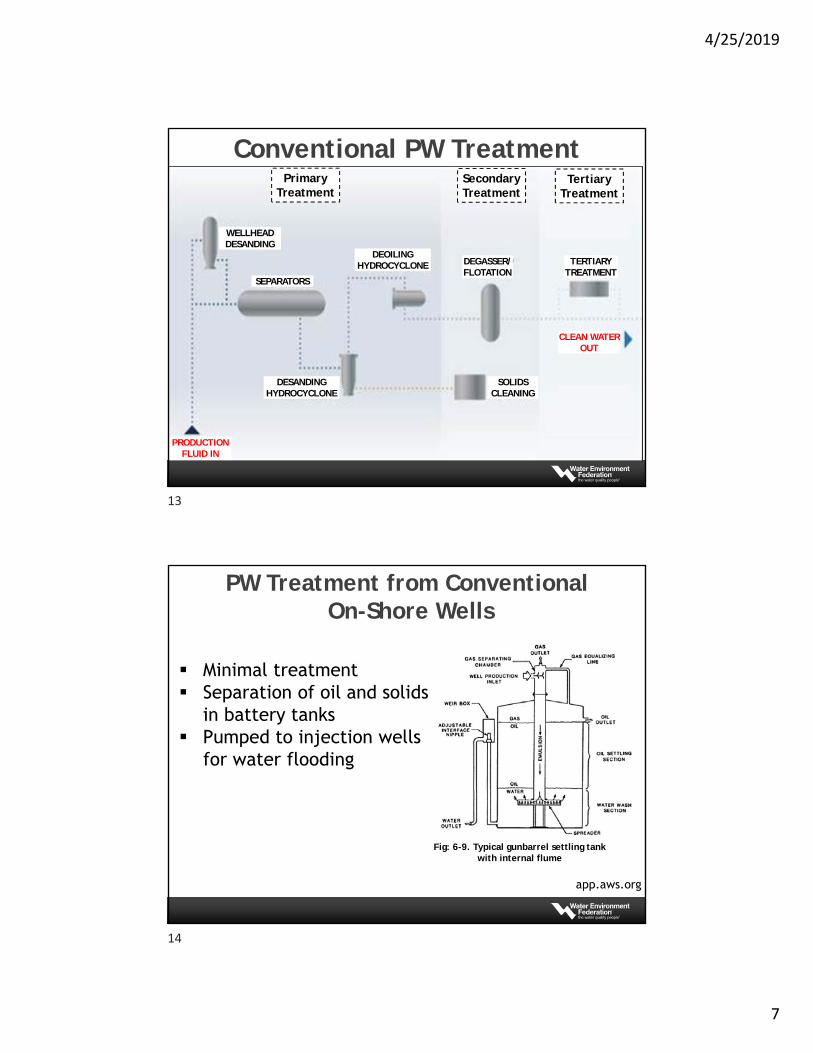
Conventional PW TreatmentPrimary
TreatmentSecondary Treatment
Tertiary Treatment
PRODUCTION FLUID IN
WELLHEAD DESANDING
SEPARATORS
DESANDING HYDROCYCLONE
DEOILING HYDROCYCLONE
SOLIDS CLEANING
DEGASSER/FLOTATION
TERTIARY TREATMENT
CLEAN WATEROUT
PW Treatment from ConventionalOn-Shore Wells
app.aws.org
Minimal treatment Separation of oil and solids
in battery tanks Pumped to injection wells
for water flooding
Fig: 6-9. Typical gunbarrel settling tank with internal flume
13
14
4/25/2019
8
Conventional Wells PW Water Flood
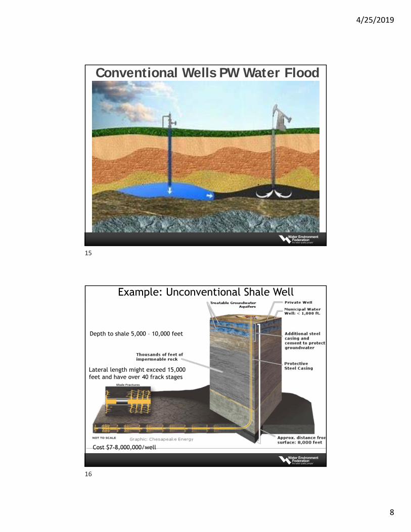
Example: Unconventional Shale Well
Depth to shale 5,000 – 10,000 feet
Lateral length might exceed 15,000 feet and have over 40 frack stages
Cost $7-8,000,000/well
15
16
4/25/2019
9
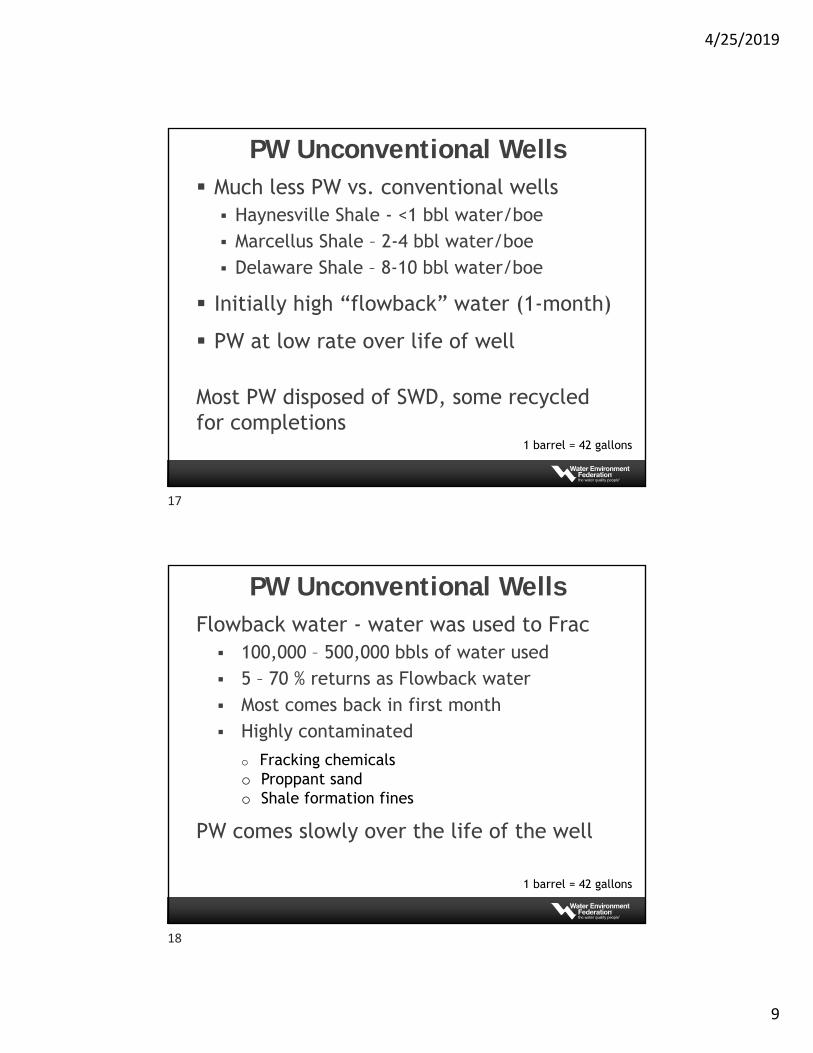
PW Unconventional Wells Much less PW vs. conventional wells Haynesville Shale - <1 bbl water/boe Marcellus Shale – 2-4 bbl water/boe Delaware Shale – 8-10 bbl water/boe
Initially high “flowback” water (1-month)
PW at low rate over life of well
Most PW disposed of SWD, some recycled for completions
1 barrel = 42 gallons
PW Unconventional WellsFlowback water - water was used to Frac 100,000 – 500,000 bbls of water used 5 – 70 % returns as Flowback water Most comes back in first month Highly contaminated
PW comes slowly over the life of the well
o Fracking chemicalso Proppant sando Shale formation fines
1 barrel = 42 gallons
17
18
4/25/2019
10
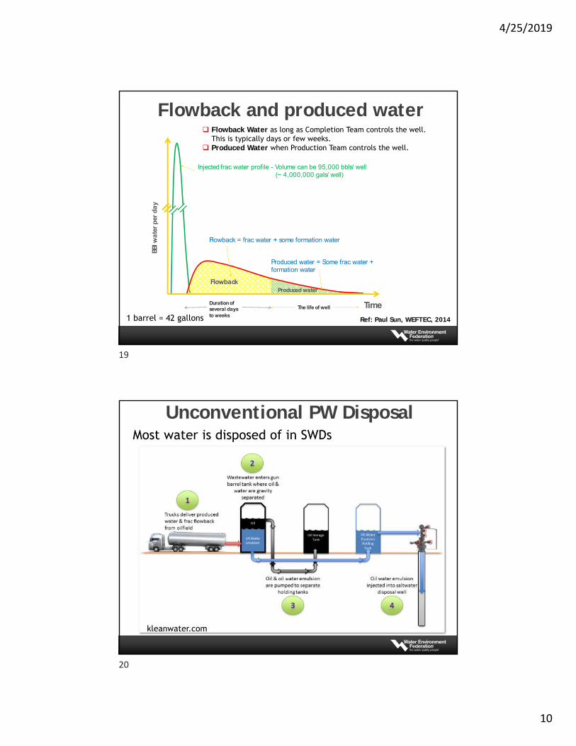
Flowback and produced water
Injected frac water profile - Volume can be 95,000 bbls/ well (~ 4,000,000 gals/ well)
FlowbackProduced water
Flowback = frac water + some formation water
BBlw
ate
r p
er d
ay
TimeDuration of several days to weeks
The life of well
Produced water = Some frac water + formation water
Flowback Water as long as Completion Team controls the well.This is typically days or few weeks.
Produced Water when Production Team controls the well.
Ref: Paul Sun, WEFTEC, 20141 barrel = 42 gallons
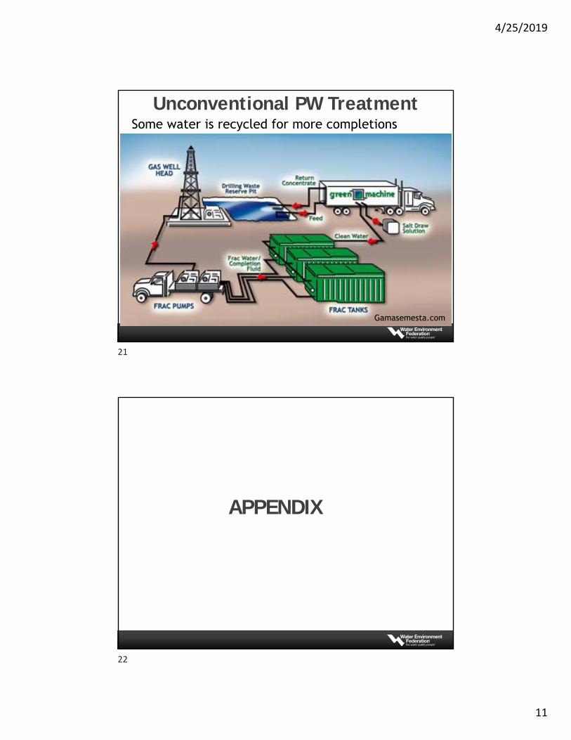
Unconventional PW Disposal
kleanwater.com
Most water is disposed of in SWDs
19
20
4/25/2019
11
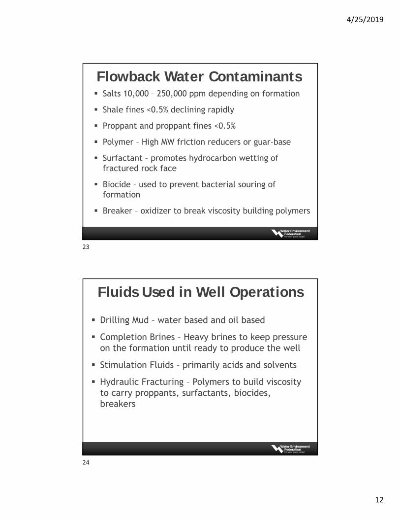
Unconventional PW TreatmentSome water is recycled for more completions
Gamasemesta.com
APPENDIX
21
22
4/25/2019
12
Flowback Water Contaminants Salts 10,000 – 250,000 ppm depending on formation
Shale fines <0.5% declining rapidly
Proppant and proppant fines <0.5%
Polymer – High MW friction reducers or guar-base
Surfactant – promotes hydrocarbon wetting of fractured rock face
Biocide – used to prevent bacterial souring of formation
Breaker – oxidizer to break viscosity building polymers
Fluids Used in Well Operations
Drilling Mud – water based and oil based
Completion Brines – Heavy brines to keep pressure on the formation until ready to produce the well
Stimulation Fluids – primarily acids and solvents
Hydraulic Fracturing – Polymers to build viscosity to carry proppants, surfactants, biocides, breakers
23
24
4/25/2019
13
Life Cycle of Produced Water with Regulatory Issues
Jill E. Cooper, JD
Senior Principal
Geosyntec Consultants
25
Overview
Water in Upstream
Water as a Product
Regulatory Issues
Collaboration and Research
Life Cycle of Produced Water with Regulatory Issues
26
25
26
4/25/2019
14
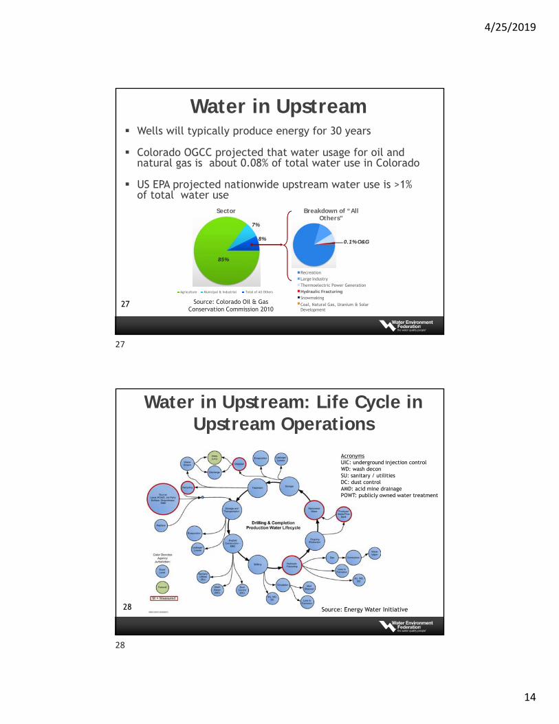
Sector
Agriculture Municipal & Industrial Total of All Others
Source: Colorado Oil & Gas Conservation Commission 2010
Breakdown of “All Others”
Recreation
Large Industry
Thermoelectric Power Generation
Hydraulic Fracturing
Snowmaking
Coal, Natural Gas, Uranium & SolarDevelopment
85%
7%
8% 0.1% O&G
Water in Upstream Wells will typically produce energy for 30 years
Colorado OGCC projected that water usage for oil and natural gas is about 0.08% of total water use in Colorado
US EPA projected nationwide upstream water use is >1% of total water use
27
Water in Upstream: Life Cycle in Upstream Operations
28 Source: Energy Water Initiative
AcronymsUIC: underground injection controlWD: wash deconSU: sanitary / utilitiesDC: dust controlAMD: acid mine drainagePOWT: publicly owned water treatment
27
28
4/25/2019
15
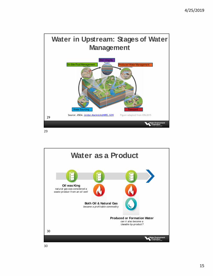
Water in Upstream: Stages of Water Management
Water Sourcing
On-Site Fluid Management
Well Integrity
Produced Water Management
Transport
Figure adapted from EPA2015Source: JISEA: [email protected] 29
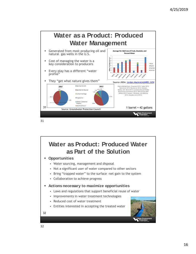
Water as a Product
302
Oil was Kingnatural gas was considered a
waste product from an oil well
Both Oil & Natural Gasbecame a profitable commodity
Produced or Formation Watercan it also become aUseable by-product?
29
30
4/25/2019
16
Water as a Product: Produced Water Management
Generated from most producing oil and natural gas wells in the U.S.
Cost of managing the water is a key consideration to producers
Every play has a different “water profile”
They “get what nature gives them”
31
Source: Ground Water Protection Council (April 2015)
Data collected from: (Freyman 2014; Taylor 2012; Nicot et al. 2014; Nicot et al. 2012; Scanlon,
Reedy, and Nicot 2014; Louisiana Ground Water Resources Commission 2012; EPA 2015a; BHP Billiton 2014; Hansen, Mulvaney, and Betcher
2013; Goodwin et al. 2014)
Source JISEA: [email protected]
Source: Groundwater Protection Council1 barrel = 42 gallons
Water as Product: Produced Water as Part of the Solution
Opportunities Water sourcing, management and disposal
Not a significant user of water compared to other sectors
Bring “trapped water” to the surface –net gain to the system
Collaboration to achieve progress
Actions necessary to maximize opportunities Laws and regulations that support beneficial reuse of water
Improvements in water treatment technologies
Reduced cost of water treatment
Entities interested in accepting the treated water
32
31
32
4/25/2019
17
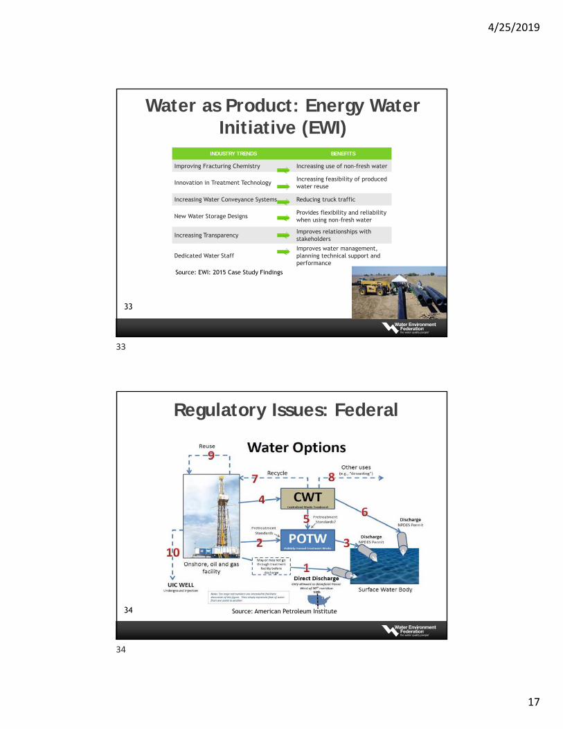
Water as Product: Energy Water Initiative (EWI)
INDUSTRY TRENDS BENEFITS
Improving Fracturing Chemistry Increasing use of non-fresh water
Innovation in Treatment TechnologyIncreasing feasibility of produced water reuse
Increasing Water Conveyance Systems Reducing truck traffic
New Water Storage DesignsProvides flexibility and reliability when using non-fresh water
Increasing TransparencyImproves relationships with stakeholders
Dedicated Water StaffImproves water management, planning technical support and performance
33
Source: EWI: 2015 Case Study Findings
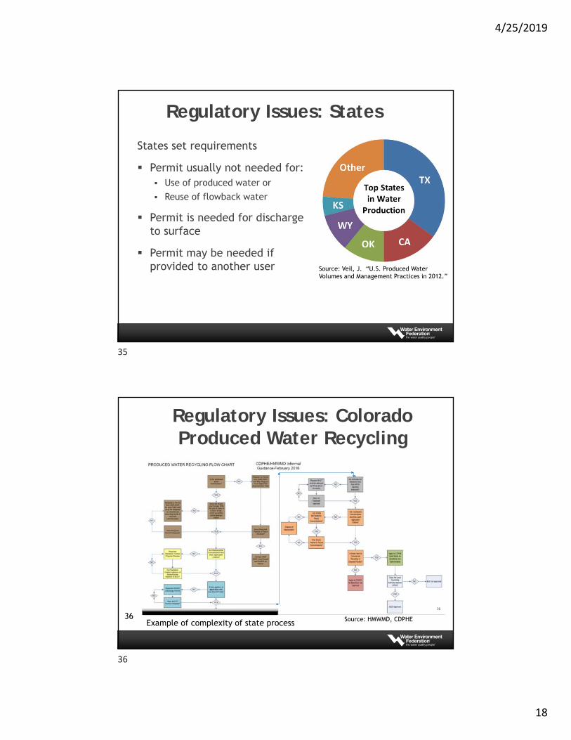
Regulatory Issues: Federal
34 Source: American Petroleum Institute
33
34
4/25/2019
18
Regulatory Issues: States
States set requirements
Permit usually not needed for: Use of produced water or
Reuse of flowback water
Permit is needed for discharge to surface
Permit may be needed if provided to another user Source: Veil, J. “U.S. Produced Water
Volumes and Management Practices in 2012.”
Regulatory Issues: Colorado Produced Water Recycling
36
36 Source: HMWMD, CDPHEExample of complexity of state process
35
36
4/25/2019
19
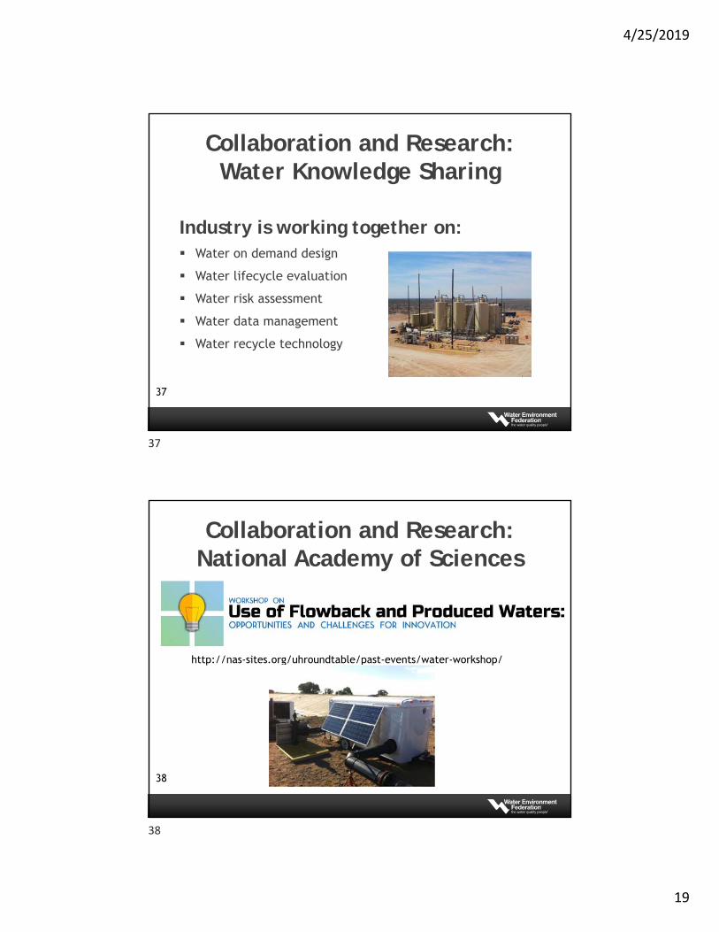
Collaboration and Research: Water Knowledge Sharing
Industry is working together on: Water on demand design
Water lifecycle evaluation
Water risk assessment
Water data management
Water recycle technology
37
Collaboration and Research: National Academy of Sciences
http://nas-sites.org/uhroundtable/past-events/water-workshop/
38
37
38
4/25/2019
20
Jill CooperSenior Principal
Geosyntec Consultants(303) 880-2915
Thank You!
39
F. Morris Hoagland, P.E.
Jade Dragon, LLC
& Produced Water Society
PW Management: Market & Treatment
Hossain M Azam, Ph.D.
Assistant Professor, Manhattan College
Chair, Upstream Oil & Gas Sub-Committee, IWWC, WEF
39
40
4/25/2019
21
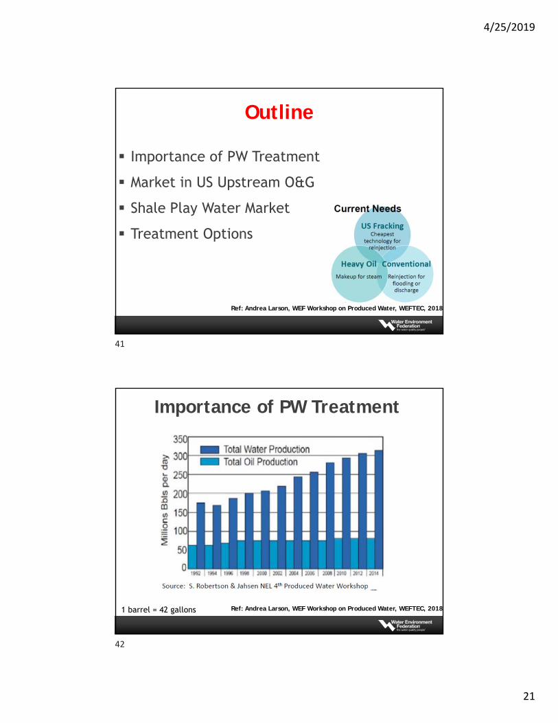
Outline
Importance of PW Treatment
Market in US Upstream O&G
Shale Play Water Market
Treatment Options
Ref: Andrea Larson, WEF Workshop on Produced Water, WEFTEC, 2018
Importance of PW Treatment
Ref: Andrea Larson, WEF Workshop on Produced Water, WEFTEC, 20181 barrel = 42 gallons
41
42
4/25/2019
22
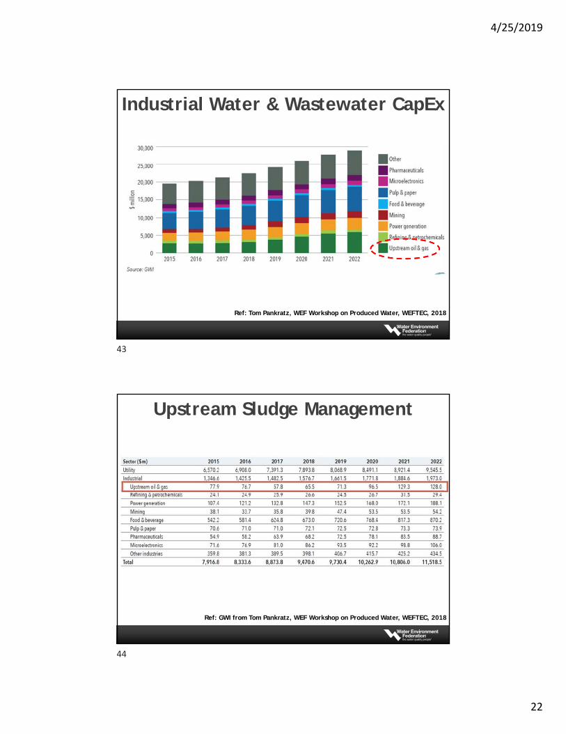
Ref: Tom Pankratz, WEF Workshop on Produced Water, WEFTEC, 2018
Industrial Water & Wastewater CapEx
Ref: GWI from Tom Pankratz, WEF Workshop on Produced Water, WEFTEC, 2018
Upstream Sludge Management
43
44
4/25/2019
23
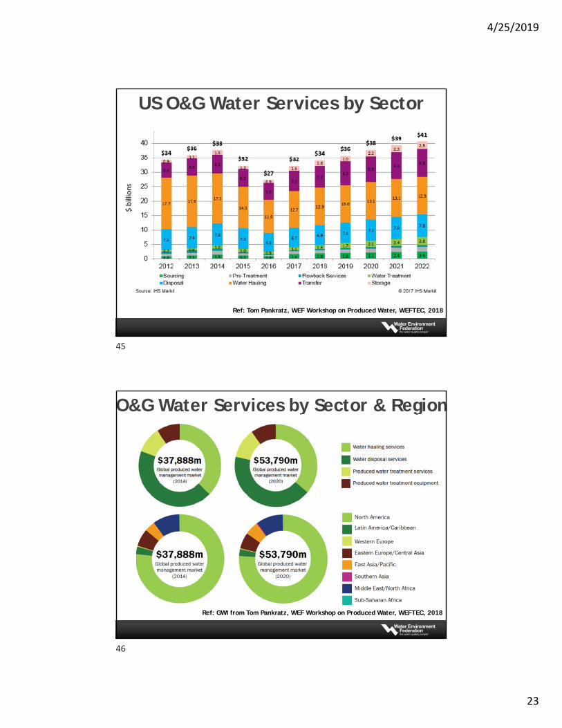
Ref: Tom Pankratz, WEF Workshop on Produced Water, WEFTEC, 2018
US O&G Water Services by Sector
Ref: GWI from Tom Pankratz, WEF Workshop on Produced Water, WEFTEC, 2018
O&G Water Services by Sector & Region
45
46
4/25/2019
24
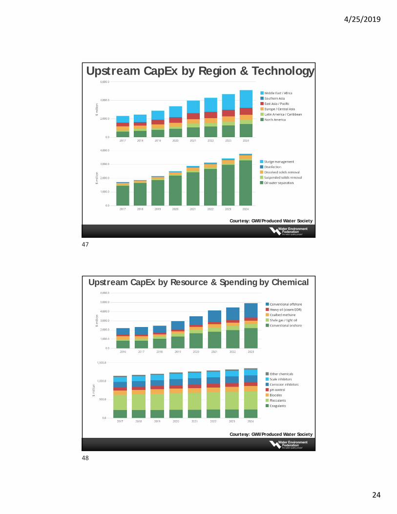
Courtesy: GWI/Produced Water Society
Upstream CapEx by Region & Technology
Courtesy: GWI/Produced Water Society
Upstream CapEx by Resource & Spending by Chemical
47
48
4/25/2019
25
Courtesy: GWI/Produced Water Society
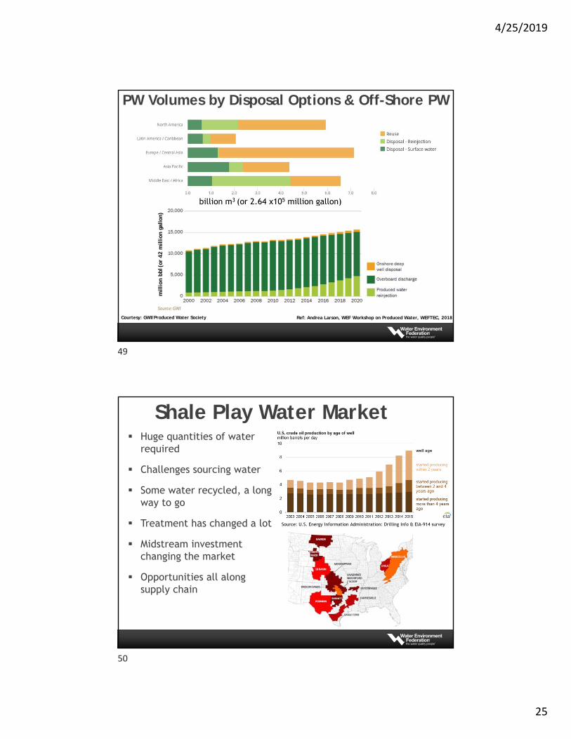
PW Volumes by Disposal Options & Off-Shore PW
billion m3 (or 2.64 x10⁵ million gallon)
Ref: Andrea Larson, WEF Workshop on Produced Water, WEFTEC, 2018
million
bbl
(or
42 m
illion
gal
lon)
Shale Play Water Market Huge quantities of water
required
Challenges sourcing water
Some water recycled, a long way to go
Treatment has changed a lot
Midstream investment changing the market
Opportunities all along supply chain
Source: U.S. Energy Information Administration: Drilling Info & EIA-914 survey
49
50
4/25/2019
26
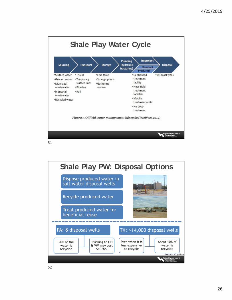
Shale Play Water Cycle
Shale Play PW: Disposal Options
Dispose produced water in salt water disposal wells
Recycle produced water
Treat produced water for beneficial reuse
PA: 8 disposal wells
Trucking to OH & WV may cost
$10/bbl
90% of the water is recycled
TX: >14,000 disposal wells
About 10% of water is recycled
Even when it is less expensive
to recycle
1 barrel = 42 gallons
51
52
4/25/2019
27
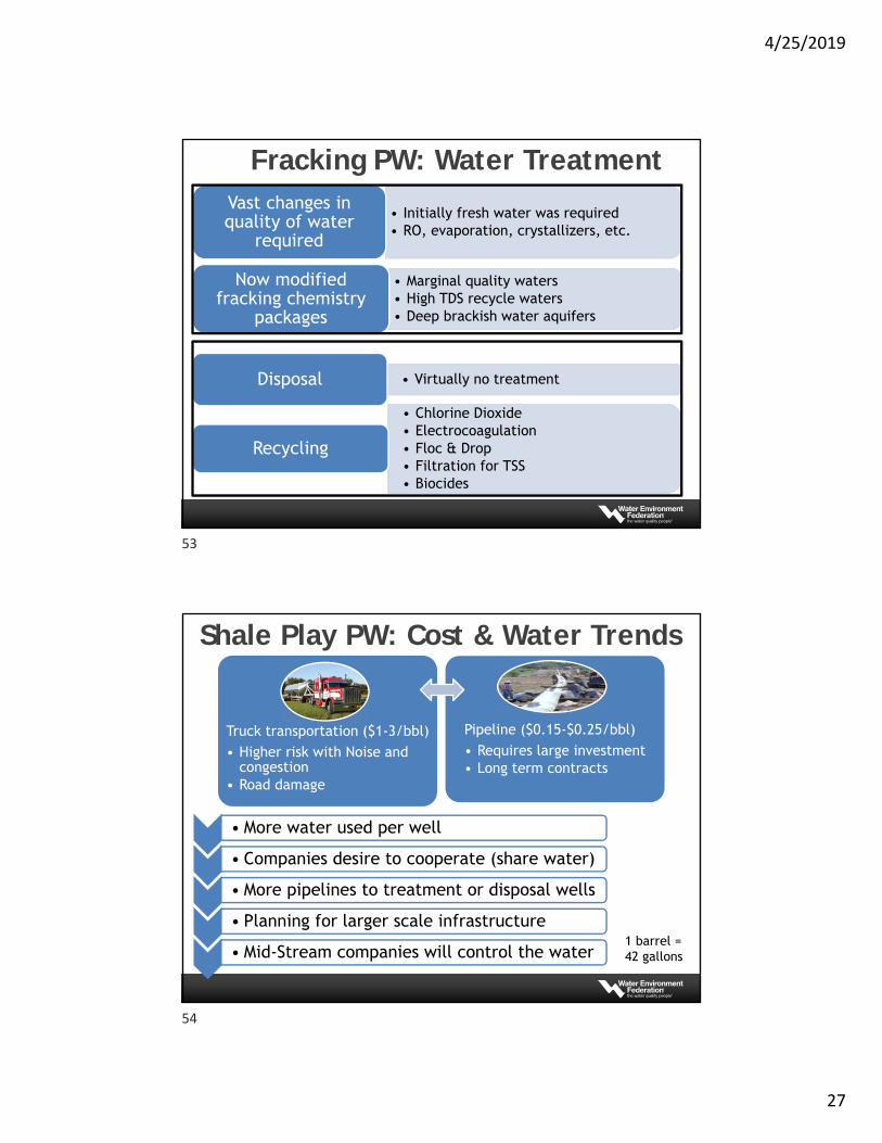
Fracking PW: Water Treatment
• Initially fresh water was required• RO, evaporation, crystallizers, etc.
Vast changes in quality of water
required
• Marginal quality waters• High TDS recycle waters• Deep brackish water aquifers
Now modified fracking chemistry
packages
• Virtually no treatmentDisposal
• Chlorine Dioxide • Electrocoagulation• Floc & Drop• Filtration for TSS• Biocides
Recycling
Shale Play PW: Cost & Water Trends
• More water used per well
• Companies desire to cooperate (share water)
• More pipelines to treatment or disposal wells
• Planning for larger scale infrastructure
• Mid-Stream companies will control the water
Truck transportation ($1-3/bbl)• Higher risk with Noise and
congestion• Road damage
Pipeline ($0.15-$0.25/bbl)• Requires large investment• Long term contracts
1 barrel = 42 gallons
53
54
4/25/2019
28
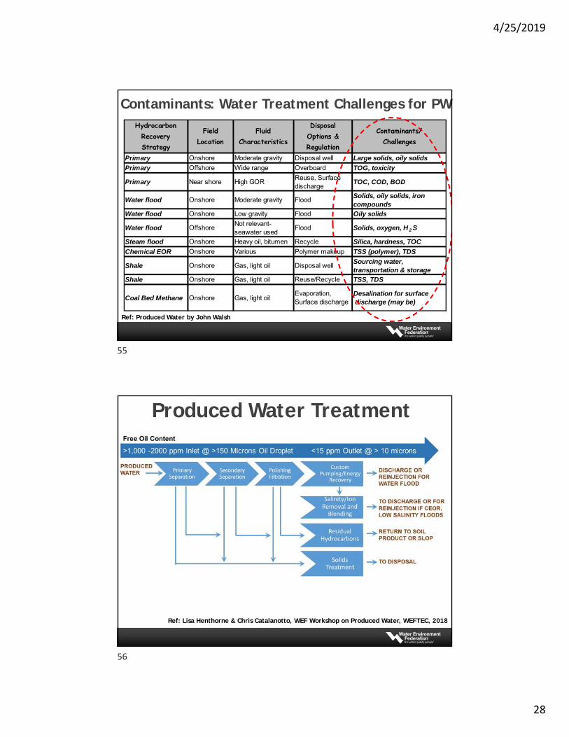
Contaminants: Water Treatment Challenges for PW
Ref: Produced Water by John Walsh
Hydrocarbon Recovery Strategy
Field Location
Fluid Characteristics
Disposal Options & Regulation
Contaminants/Challenges
Primary Onshore Moderate gravity Disposal well Large solids, oily solids
Primary Offshore Wide range Overboard TOG, toxicity
Primary Near shore High GORReuse, Surface discharge
TOC, COD, BOD
Water flood Onshore Moderate gravity FloodSolids, oily solids, iron compounds
Water flood Onshore Low gravity Flood Oily solids
Water flood OffshoreNot relevant-seawater used
Flood Solids, oxygen, H 2 S
Steam flood Onshore Heavy oil, bitumen Recycle Silica, hardness, TOC
Chemical EOR Onshore Various Polymer makeup TSS (polymer), TDS
Shale Onshore Gas, light oil Disposal wellSourcing water, transportation & storage
Shale Onshore Gas, light oil Reuse/Recycle TSS, TDS
Coal Bed Methane Onshore Gas, light oilEvaporation, Surface discharge
Desalination for surface discharge (may be)
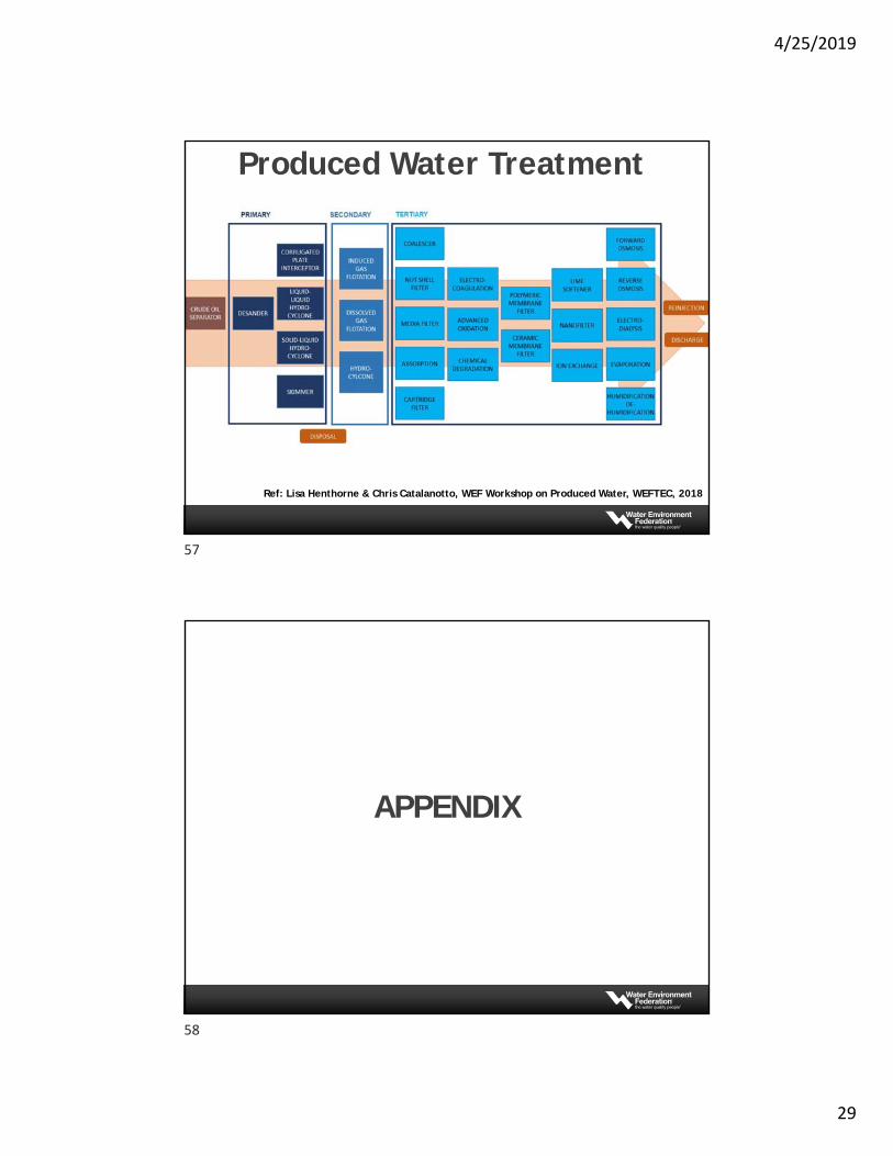
Produced Water Treatment
Ref: Lisa Henthorne & Chris Catalanotto, WEF Workshop on Produced Water, WEFTEC, 2018
55
56
4/25/2019
29
Produced Water Treatment
Ref: Lisa Henthorne & Chris Catalanotto, WEF Workshop on Produced Water, WEFTEC, 2018
APPENDIX
57
58
4/25/2019
30
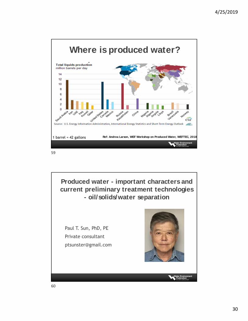
Where is produced water?
Ref: Andrea Larson, WEF Workshop on Produced Water, WEFTEC, 20181 barrel = 42 gallons
Paul T. Sun, PhD, PE
Private consultant
Produced water - important characters and current preliminary treatment technologies
- oil/solids/water separation
59
60
4/25/2019
31
1. INTRODUCTION2. IMPORTANT PARAMETERS - oil3. IMPORTANT PARAMETERS - suspended solids4. APPLICATIONS - conventional vs unconventional5. BASIC THEORY6. IMPORTANCE OF PARTICLE SIZE 7. COAGULATION & FLOCCULATION8. GRAVITY SEPARATION9. CENTRIFUGAL SEPARATION10.FLOTATION PROCESSES11.FILTRATION PROCESS12.SUMMARY
APPENDIX
OUTLINE
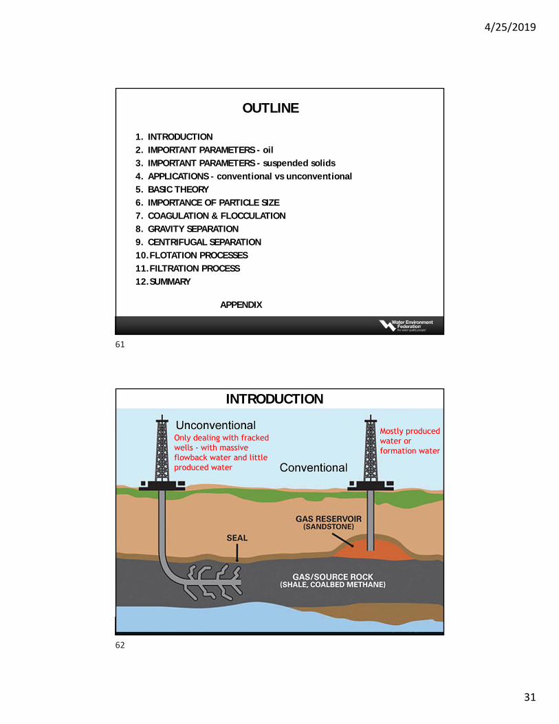
INTRODUCTION
Only dealing with fracked wells - with massive flowback water and little produced water
Mostly produced water or formation water
61
62
4/25/2019
32
The most important parameters for produced water oil/solids/water separation
1. Conventional produced water: Highly salty formation water - TDS (50,000 to 250,000 mg/L) Oil in water after Free Water Knock Out (FWKO) - usually not heavily
emulsified, Low TSS concentration - mostly formed at the surface (scaling particles,
precipitated sulfur or FeS, asphaltenes formed sticky deposits). They should be dealt with by chemical means in front of treatment,
Oil in water dominating wastewater - flotation based treatment
2. Unconventional produced water (flowback and produced water from frac) Highly salty formation water but flowback water can be different, Oil in water heavily emulsified with fracturing debris and chemicals (gum),
although the produced oil itself is lighter, Lots of suspended solids mixed with oily material. Requiring chemical
coagulation to separate the heavier flocs for cleanup, Stabilized solids/oil mixture dominating wastewater - Coagulation and
solids liquid separation, either settling or DAF
INTRODUCTION
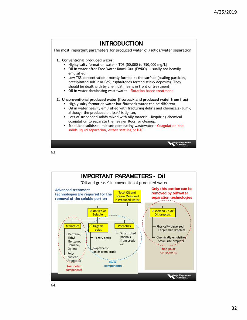
Total Oil and Grease Measured in Produced water
Dissolved or Soluble
Dispersed Crude Oil droplets
Aromatics Organic acids
Phenolics
Benzene, Ethyl Benzene, Toluene, Xylene
Poly-nuclear Aromatics
Fatty acids
Naphthenic acids from crude
Substituted phenols from crude oil
Physically dispersedLarger size droplets
Chemically emulsifiedSmall size droplets
Polar components
Non-polar components
Non-polar components
Only this portion can be removed by oil/water separation technologies
Advanced treatment technologies are required for the removal of the soluble portion
"Oil and grease" in conventional produced water
IMPORTANT PARAMETERS - Oil
63
64
4/25/2019
33
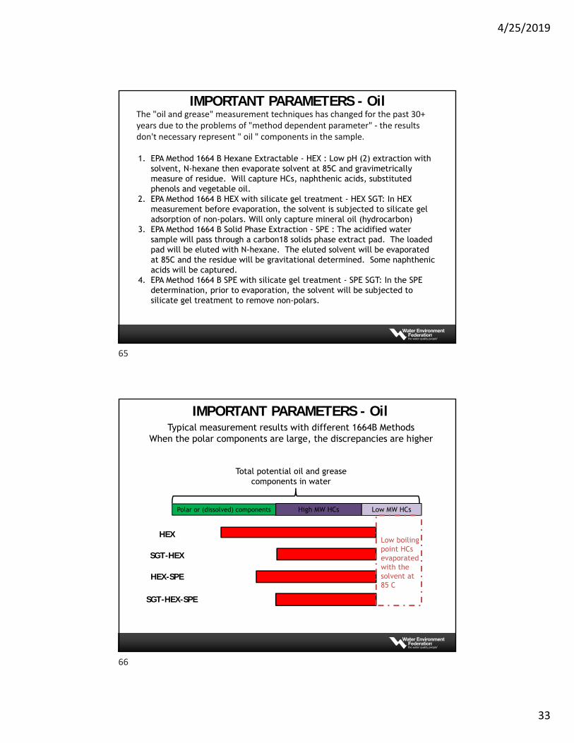
The "oil and grease" measurement techniques has changed for the past 30+ years due to the problems of "method dependent parameter" ‐ the results don't necessary represent " oil " components in the sample.
1. EPA Method 1664 B Hexane Extractable - HEX : Low pH (2) extraction with solvent, N-hexane then evaporate solvent at 85C and gravimetrically measure of residue. Will capture HCs, naphthenic acids, substituted phenols and vegetable oil.
2. EPA Method 1664 B HEX with silicate gel treatment - HEX SGT: In HEX measurement before evaporation, the solvent is subjected to silicate gel adsorption of non-polars. Will only capture mineral oil (hydrocarbon)
3. EPA Method 1664 B Solid Phase Extraction - SPE : The acidified water sample will pass through a carbon18 solids phase extract pad. The loaded pad will be eluted with N-hexane. The eluted solvent will be evaporated at 85C and the residue will be gravitational determined. Some naphthenic acids will be captured.
4. EPA Method 1664 B SPE with silicate gel treatment - SPE SGT: In the SPE determination, prior to evaporation, the solvent will be subjected to silicate gel treatment to remove non-polars.
IMPORTANT PARAMETERS - Oil
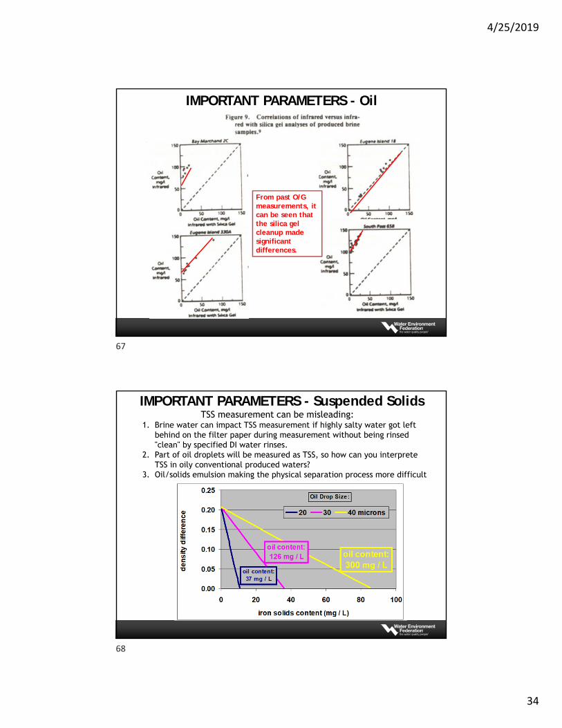
Polar or (dissolved) components High MW HCs Low MW HCs
HEX
SGT-HEX
HEX-SPE
SGT-HEX-SPE
Typical measurement results with different 1664B MethodsWhen the polar components are large, the discrepancies are higher
Total potential oil and grease components in water
Low boiling point HCs evaporated with the solvent at 85 C
IMPORTANT PARAMETERS - Oil
65
66
4/25/2019
34
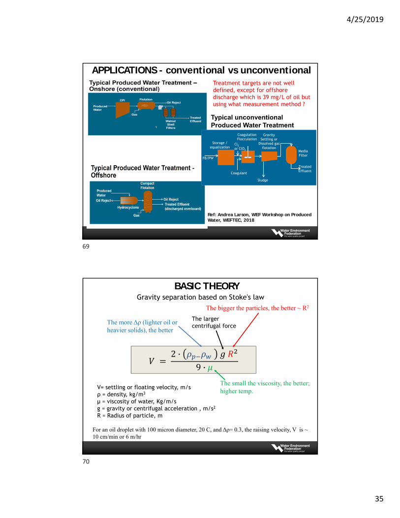
From past O/G measurements, it can be seen that the silica gel cleanup made significant differences.
IMPORTANT PARAMETERS - Oil
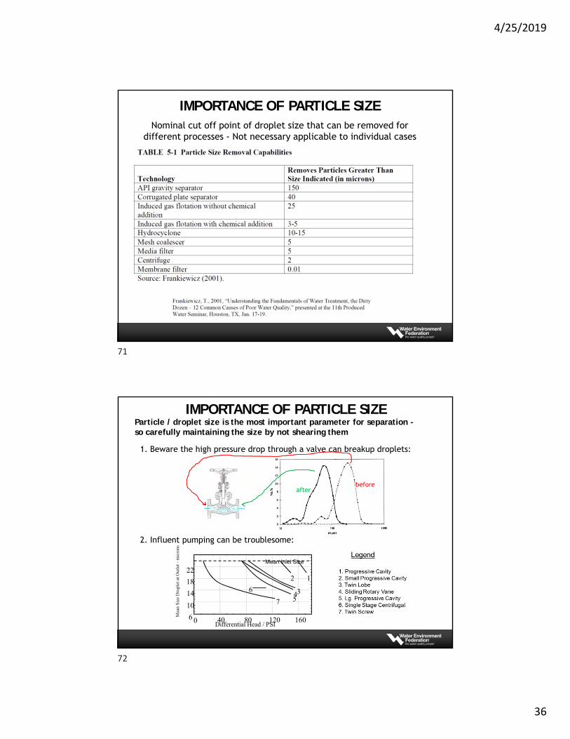
TSS measurement can be misleading:1. Brine water can impact TSS measurement if highly salty water got left
behind on the filter paper during measurement without being rinsed "clean" by specified DI water rinses.
2. Part of oil droplets will be measured as TSS, so how can you interpreteTSS in oily conventional produced waters?
3. Oil/solids emulsion making the physical separation process more difficult
IMPORTANT PARAMETERS - Suspended Solids
67
68
4/25/2019
35
Storage / equalization
CoagulationFlocculation
Gravity Settling or
Dissolved gas flotation
MediaFilter
FB/PW
TreatedEffluentCoagulant
Typical unconventional Produced Water Treatment
Cl2or ClO2
Sludge
APPLICATIONS - conventional vs unconventionalTreatment targets are not well defined, except for offshore discharge which is 39 mg/L of oil but using what measurement method ?
Ref: Andrea Larson, WEF Workshop on Produced Water, WEFTEC, 2018
For an oil droplet with 100 micron diameter, 20 C, and Δρ= 0.3, the raising velocity, V is ~ 10 cm/min or 6 m/hr
Gravity separation based on Stoke's law
The small the viscosity, the better; higher temp.
The more Δρ (lighter oil or heavier solids), the better
The bigger the particles, the better ⁓ R2
𝑉 2 · 𝜌 𝜌 𝑔 𝑅
9 · 𝜇
The larger centrifugal force
V= settling or floating velocity, m/sρ = density, kg/m3
µ = viscosity of water, Kg/m/sg = gravity or centrifugal acceleration , m/s2
R = Radius of particle, m
BASIC THEORY
69
70
4/25/2019
36
Nominal cut off point of droplet size that can be removed for different processes - Not necessary applicable to individual cases
IMPORTANCE OF PARTICLE SIZE
Particle / droplet size is the most important parameter for separation -so carefully maintaining the size by not shearing them
1. Beware the high pressure drop through a valve can breakup droplets:
2. Influent pumping can be troublesome:
beforeafter
Mean Inlet Size
2 1
7 5436
0 40 80 120 160Differential Head / PSI
10
14
18
22
6Mea
n S
ize
Dro
plet
at O
utle
t -m
icro
ns
IMPORTANCE OF PARTICLE SIZE
71
72
4/25/2019
37
73
+
++ +++ +
+++
+
+
+
++
+
+
+
+
+
+
+
+
+
+
+
+ +
++
+
+
++
+
+
+
++
++
+
+
+
+
+
+
+
+
+
+++
+
+
+
+
+
+
+
+
+
+ +
++
+
+
++
+
+
+
++
++
+
+
+
+
+
+
+
+
+
+++
+
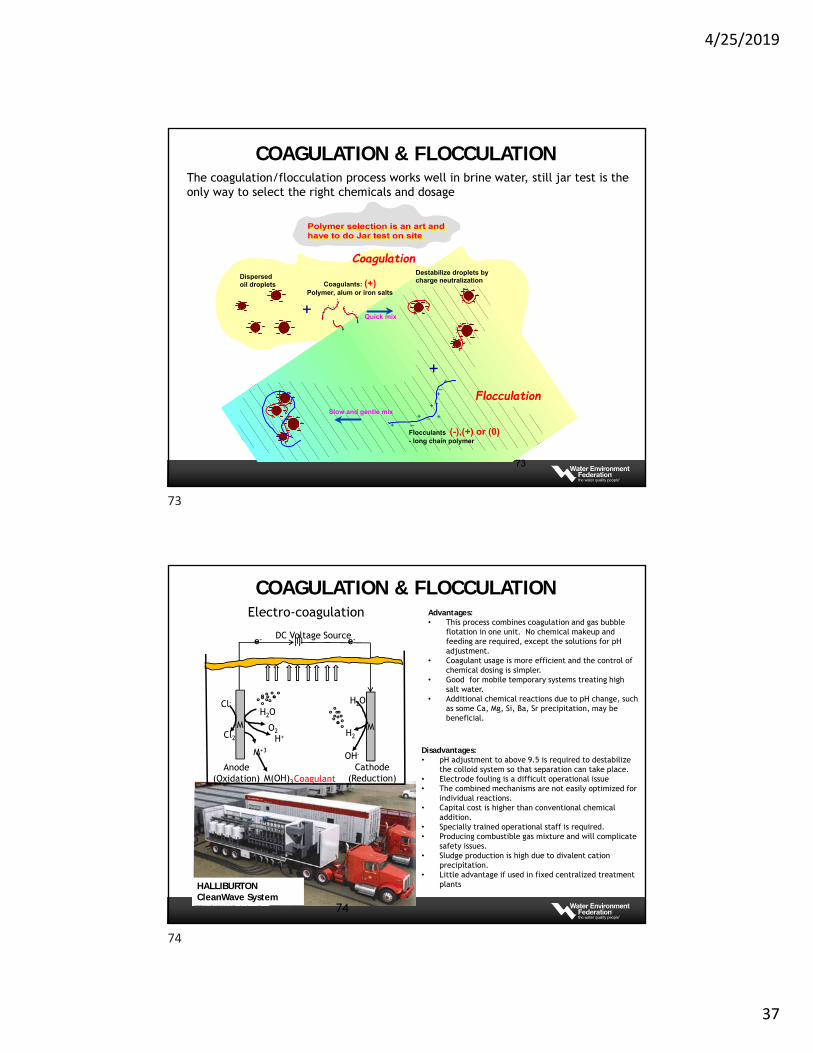
Dispersedoil droplets Coagulants: (+)
Polymer, alum or iron salts
Destabilize droplets bycharge neutralization
Quick mix
++
+
+
+
__
_
_
Slow and gentle mix
Flocculants (-),(+) or (0)- long chain polymer
Coagulation
Flocculation
The coagulation/flocculation process works well in brine water, still jar test is the only way to select the right chemicals and dosage
COAGULATION & FLOCCULATION
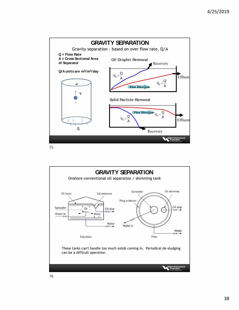
Electro-coagulation
M
e- e-
M
M+3
M(OH)3
Anode(Oxidation)
Cathode(Reduction)
H2O
H2
OH-
H2O
O2H+
Cl-
Cl2
DC Voltage Source
Coagulant
Advantages:• This process combines coagulation and gas bubble
flotation in one unit. No chemical makeup and feeding are required, except the solutions for pH adjustment.
• Coagulant usage is more efficient and the control of chemical dosing is simpler.
• Good for mobile temporary systems treating high salt water.
• Additional chemical reactions due to pH change, such as some Ca, Mg, Si, Ba, Sr precipitation, may be beneficial.
Disadvantages:• pH adjustment to above 9.5 is required to destabilize
the colloid system so that separation can take place.• Electrode fouling is a difficult operational issue• The combined mechanisms are not easily optimized for
individual reactions.• Capital cost is higher than conventional chemical
addition.• Specially trained operational staff is required.• Producing combustible gas mixture and will complicate
safety issues.• Sludge production is high due to divalent cation
precipitation.• Little advantage if used in fixed centralized treatment
plantsHALLIBURTON CleanWave System
74
COAGULATION & FLOCCULATION
73
74
4/25/2019
38
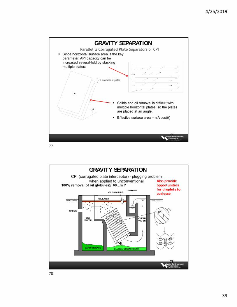
Oil Droplet RemovalQ = Flow RateA = Cross Sectional Area of Separator
Q/A units are m3/m2/day
A
QVR
A
QVR Effluent
Recovery
Flow Direction
Solid Particle Removal
A
QVR
A
QVR Effluent
Recovery
Flow Direction
Gravity separation - based on over flow rate, Q/A
Q
V
GRAVITY SEPARATION
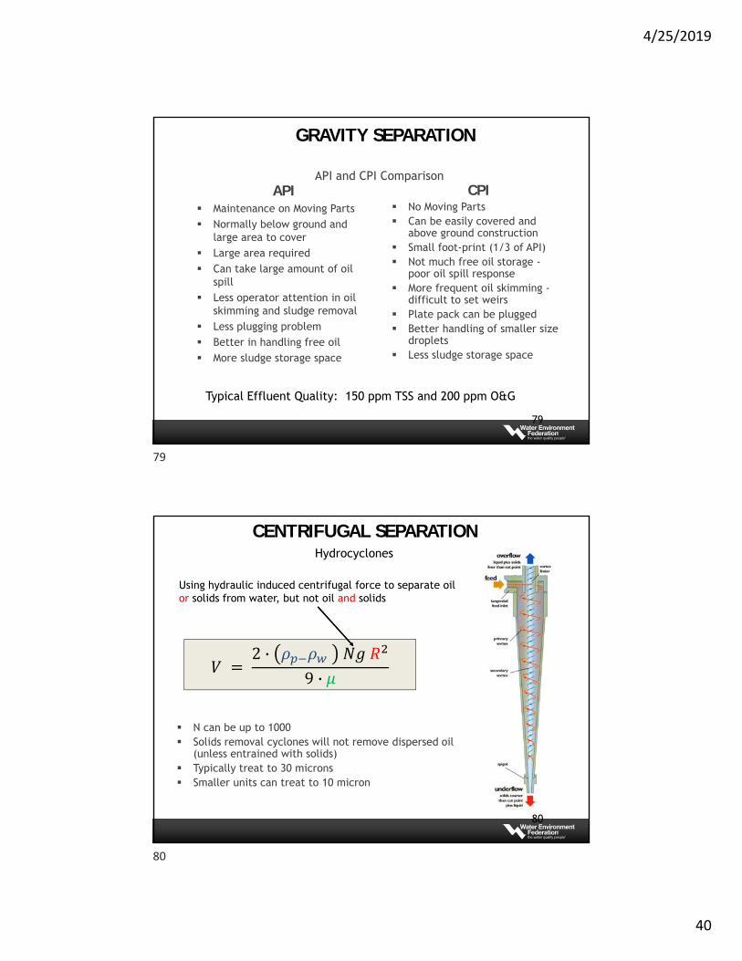
Onshore conventional oil separation / skimming tank
These tanks can't handle too much solids coming in. Periodical de-sludgingcan be a difficult operation.
GRAVITY SEPARATION
75
76
4/25/2019
39
77
Parallel & Corrugated Plate Separators or CPI
} = number of plates
A
n
Since horizontal surface area is the key parameter, API capacity can be increased several-fold by stacking multiple plates:
Solids and oil removal is difficult with multiple horizontal plates, so the plates are placed at an angle.
Effective surface area = n A cos()
GRAVITY SEPARATION
78
CPI (corrugated plate interceptor) - plugging problem when applied to unconventional
100% removal of oil globules 60 m ?
OILLAYER
INFLOW
OILY WATER
CLEAN WATER
OUTFLOW
SAND STORAGE SLUDGE COMPARTMENT
OILSKIM PIPE
D
silt oil
silt
silt oil
silt
Also provide opportunities for droplets to coalesce
GRAVITY SEPARATION
77
78
4/25/2019
40
API and CPI ComparisonAPI
Maintenance on Moving Parts Normally below ground and
large area to cover Large area required Can take large amount of oil
spill Less operator attention in oil
skimming and sludge removal Less plugging problem Better in handling free oil More sludge storage space
CPI No Moving Parts Can be easily covered and
above ground construction Small foot-print (1/3 of API) Not much free oil storage -
poor oil spill response More frequent oil skimming -
difficult to set weirs Plate pack can be plugged Better handling of smaller size
droplets Less sludge storage space
Typical Effluent Quality: 150 ppm TSS and 200 ppm O&G
79
GRAVITY SEPARATION
N can be up to 1000 Solids removal cyclones will not remove dispersed oil
(unless entrained with solids) Typically treat to 30 microns Smaller units can treat to 10 micron
𝑉 2 · 𝜌 𝜌 𝑁𝑔 𝑅
9 · 𝜇
Using hydraulic induced centrifugal force to separate oil or solids from water, but not oil and solids
80
Hydrocyclones
CENTRIFUGAL SEPARATION
79
80
4/25/2019
41
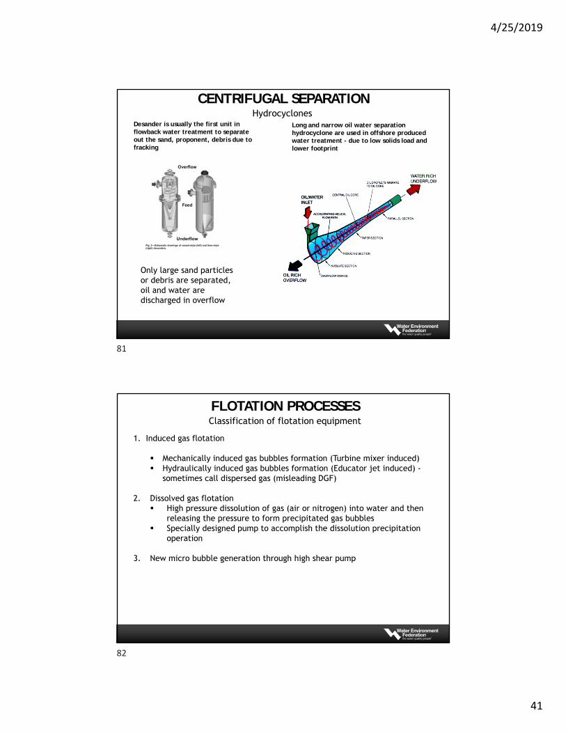
Desander is usually the first unit in flowback water treatment to separate out the sand, proponent, debris due to fracking
Only large sand particles or debris are separated, oil and water are discharged in overflow
Long and narrow oil water separation hydrocyclone are used in offshore produced water treatment - due to low solids load and lower footprint
HydrocyclonesCENTRIFUGAL SEPARATION
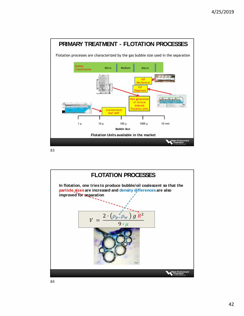
Classification of flotation equipment
1. Induced gas flotation
Mechanically induced gas bubbles formation (Turbine mixer induced) Hydraulically induced gas bubbles formation (Educator jet induced) -
sometimes call dispersed gas (misleading DGF)
2. Dissolved gas flotation High pressure dissolution of gas (air or nitrogen) into water and then
releasing the pressure to form precipitated gas bubbles Specially designed pump to accomplish the dissolution precipitation
operation
3. New micro bubble generation through high shear pump
FLOTATION PROCESSES
81
82
4/25/2019
42
1 µ 10 µ 100 µ 1000 µ 10 mm
IGFMechanical
ConventionalDAF, DNF
New generation of vertical Induced
Flotation units
Micro MacroMediumBubbleClassification
Bubble Size
IGF Dispersed
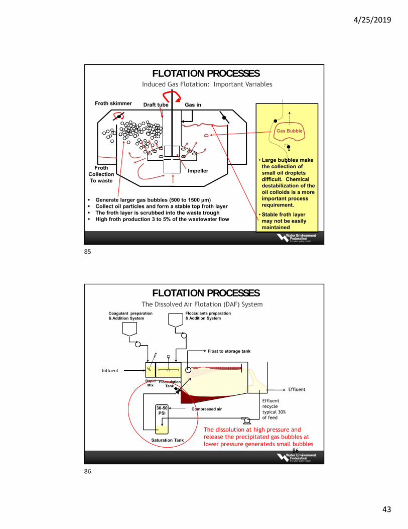
Flotation processes are characterized by the gas bubble size used in the separation
Flotation Units available in the market
PRIMARY TREATMENT - FLOTATION PROCESSES
𝑉 2 · 𝜌 𝜌 𝑔 𝑅
9 · 𝜇
In flotation, one tries to produce bubble/oil coalescent so that the particle sizes are increased and density differences are also improved for separation
FLOTATION PROCESSES
83
84
4/25/2019
43
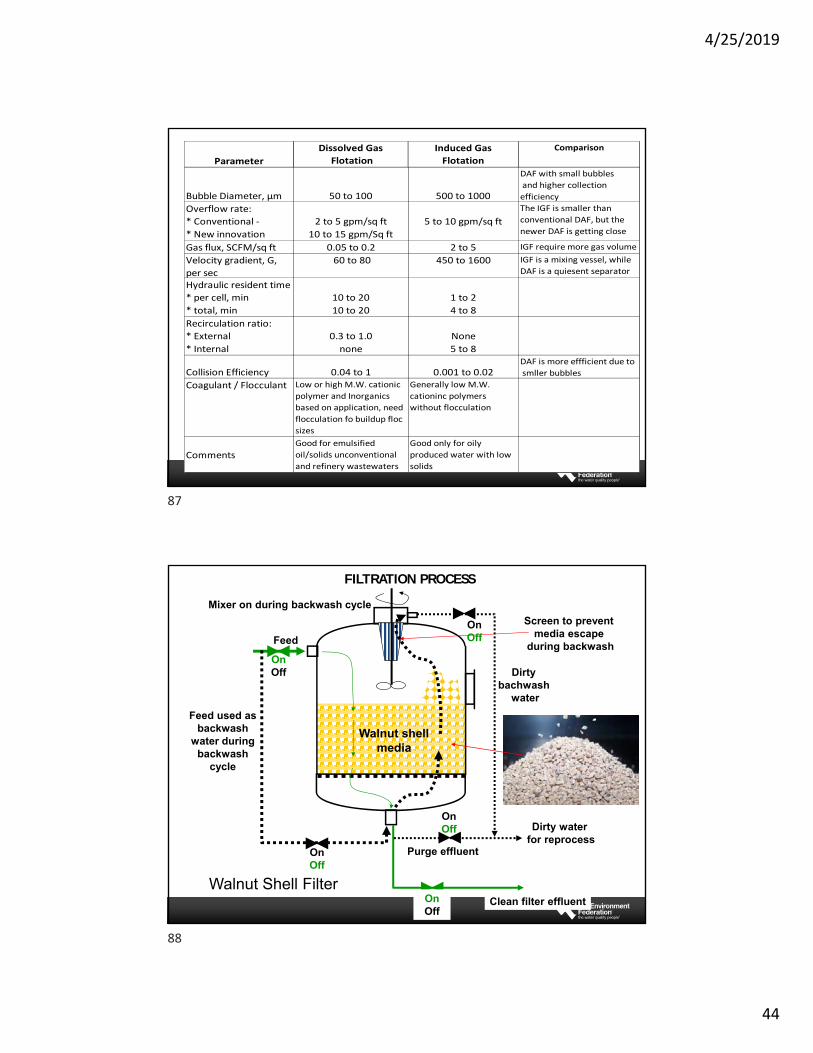
Generate larger gas bubbles (500 to 1500 µm) Collect oil particles and form a stable top froth layer The froth layer is scrubbed into the waste trough High froth production 3 to 5% of the wastewater flow
Gas inDraft tubeFroth skimmer
FrothCollectionTo waste
Impeller
Gas Bubble
• Large bubbles make the collection of small oil droplets difficult. Chemical destabilization of the oil colloids is a more important process requirement.
• Stable froth layer may not be easily maintained
Induced Gas Flotation: Important Variables
FLOTATION PROCESSES
86
Coagulant preparation & Addition System
RapidMix
FlocculationTank
Compressed air
Float to storage tank
Saturation Tank
30-50PSI
Flocculants preparation & Addition System
The Dissolved Air Flotation (DAF) System
The dissolution at high pressure and release the precipitated gas bubbles at lower pressure generateds small bubbles
FLOTATION PROCESSES
Influent
Effluent
Effluent recycle typical 30% of feed
85
86
4/25/2019
44
Parameter
Dissolved Gas
Flotation
Induced Gas
Flotation
Comparison
Bubble Diameter, µm 50 to 100 500 to 1000
DAF with small bubbles
and higher collection
efficiency
Overflow rate:
* Conventional ‐
* New innovation
2 to 5 gpm/sq ft
10 to 15 gpm/Sq ft
5 to 10 gpm/sq ft
The IGF is smaller than
conventional DAF, but the
newer DAF is getting close
Gas flux, SCFM/sq ft 0.05 to 0.2 2 to 5 IGF require more gas volume
Velocity gradient, G,
per sec
60 to 80 450 to 1600 IGF is a mixing vessel, while
DAF is a quiesent separator
Hydraulic resident time
* per cell, min
* total, min
10 to 20
10 to 20
1 to 2
4 to 8
Recirculation ratio:
* External
* Internal
0.3 to 1.0
none
None
5 to 8
Collision Efficiency 0.04 to 1 0.001 to 0.02DAF is more effficient due to
smller bubbles
Coagulant / Flocculant Low or high M.W. cationic
polymer and Inorganics
based on application, need
flocculation fo buildup floc
sizes
Generally low M.W.
cationinc polymers
without flocculation
CommentsGood for emulsified
oil/solids unconventional
and refinery wastewaters
Good only for oily
produced water with low
solids
Purge effluent
Feed
Feed used as backwash
water during backwash
cycle
Dirty bachwash
water
Dirty water for reprocess
Clean filter effluent
Mixer on during backwash cycle
Screen to prevent media escape
during backwash
Walnut shellmedia
OnOff
OnOff
On Off
On Off
On Off
Walnut Shell Filter
FILTRATION PROCESS
87
88
4/25/2019
45
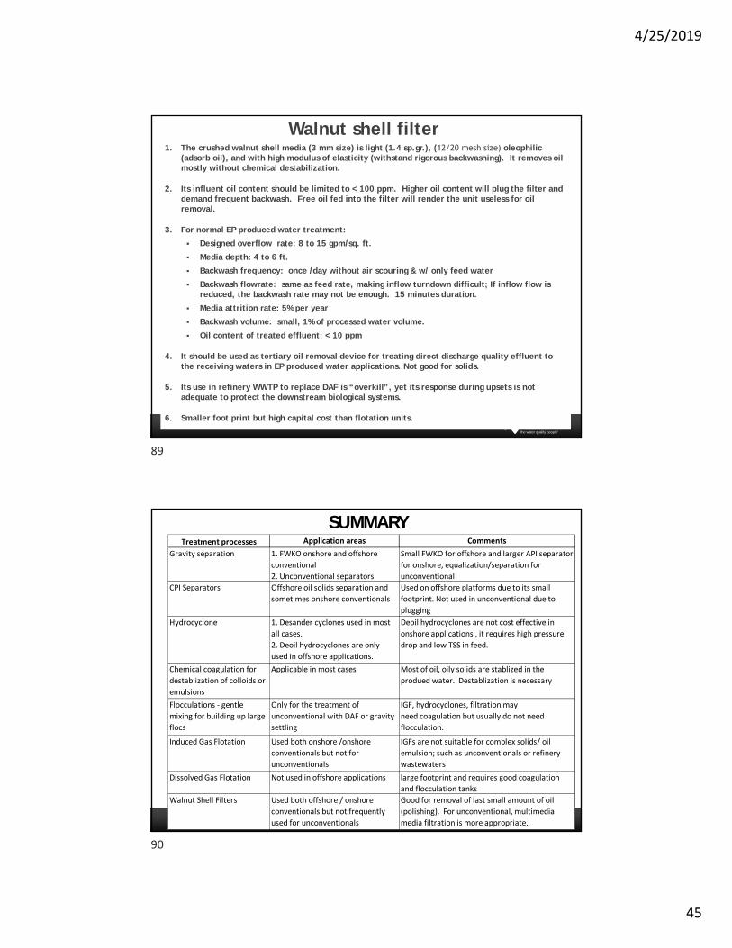
Walnut shell filter1. The crushed walnut shell media (3 mm size) is light (1.4 sp.gr.), (12/20 mesh size) oleophilic
(adsorb oil), and with high modulus of elasticity (withstand rigorous backwashing). It removes oil mostly without chemical destabilization.
2. Its influent oil content should be limited to < 100 ppm. Higher oil content will plug the filter and demand frequent backwash. Free oil fed into the filter will render the unit useless for oil removal.
3. For normal EP produced water treatment:
Designed overflow rate: 8 to 15 gpm/sq. ft.
Media depth: 4 to 6 ft.
Backwash frequency: once /day without air scouring & w/ only feed water
Backwash flowrate: same as feed rate, making inflow turndown difficult; If inflow flow is reduced, the backwash rate may not be enough. 15 minutes duration.
Media attrition rate: 5% per year
Backwash volume: small, 1% of processed water volume.
Oil content of treated effluent: < 10 ppm
4. It should be used as tertiary oil removal device for treating direct discharge quality effluent to the receiving waters in EP produced water applications. Not good for solids.
5. Its use in refinery WWTP to replace DAF is “overkill”, yet its response during upsets is not adequate to protect the downstream biological systems.
6. Smaller foot print but high capital cost than flotation units.
SUMMARYTreatment processes Application areas Comments
Gravity separation 1. FWKO onshore and offshore
conventional
2. Unconventional separators
Small FWKO for offshore and larger API separator
for onshore, equalization/separation for
unconventional
CPI Separators Offshore oil solids separation and
sometimes onshore conventionals
Used on offshore platforms due to its small
footprint. Not used in unconventional due to
plugging
Hydrocyclone 1. Desander cyclones used in most
all cases,
2. Deoil hydrocyclones are only
used in offshore applications.
Deoil hydrocyclones are not cost effective in
onshore applications , it requires high pressure
drop and low TSS in feed.
Chemical coagulation for
destablization of colloids or
emulsions
Applicable in most cases Most of oil, oily solids are stablized in the
produed water. Destablization is necessary
Flocculations ‐ gentle
mixing for building up large
flocs
Only for the treatment of
unconventional with DAF or gravity
settling
IGF, hydrocyclones, filtration may
need coagulation but usually do not need
flocculation.
Induced Gas Flotation Used both onshore /onshore
conventionals but not for
unconventionals
IGFs are not suitable for complex solids/ oil
emulsion; such as unconventionals or refinery
wastewaters
Dissolved Gas Flotation Not used in offshore applications large footprint and requires good coagulation
and flocculation tanks
Walnut Shell Filters Used both offshore / onshore
conventionals but not frequently
used for unconventionals
Good for removal of last small amount of oil
(polishing). For unconventional, multimedia
media filtration is more appropriate.
89
90
4/25/2019
46
Appendix
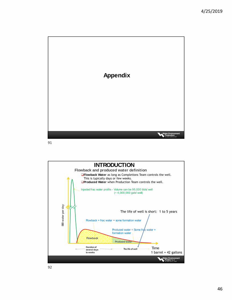
Flowback and produced water definition
92
Flowback Water as long as Completions Team controls the well.This is typically days or few weeks.
Produced Water when Production Team controls the well.
Injected frac water profile - Volume can be 95,000 bbls/ well (~ 4,000,000 gals/ well)
FlowbackProduced water
Flowback = frac water + some formation water
BBlw
ate
r p
er d
ay
TimeDuration of several days to weeks
The life of well
Produced water = Some frac water + formation water
The life of well is short: 1 to 5 years
INTRODUCTION
1 barrel = 42 gallons
91
92
4/25/2019
47
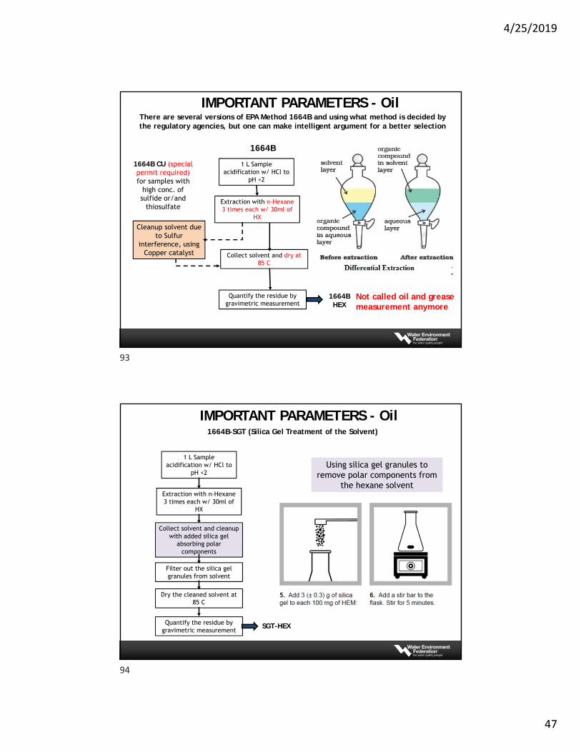
There are several versions of EPA Method 1664B and using what method is decided by the regulatory agencies, but one can make intelligent argument for a better selection
1664B
1664B CU (special permit required) for samples with
high conc. of sulfide or/and
thiosulfate
1 L Sample acidification w/ HCl to
pH <2
Extraction with n-Hexane3 times each w/ 30ml of
HX
Collect solvent and dry at 85 C
Quantify the residue by gravimetric measurement
Cleanup solvent due to Sulfur
interference, using Copper catalyst
1664BHEX
Not called oil and grease measurement anymore
IMPORTANT PARAMETERS - Oil
1664B-SGT (Silica Gel Treatment of the Solvent)
1 L Sample acidification w/ HCl to
pH <2
Extraction with n-Hexane3 times each w/ 30ml of
HX
Dry the cleaned solvent at 85 C
Quantify the residue by gravimetric measurement
Collect solvent and cleanup with added silica gel
absorbing polar components
Using silica gel granules to remove polar components from
the hexane solvent
Filter out the silica gel granules from solvent
SGT-HEX
IMPORTANT PARAMETERS - Oil
93
94
4/25/2019
48
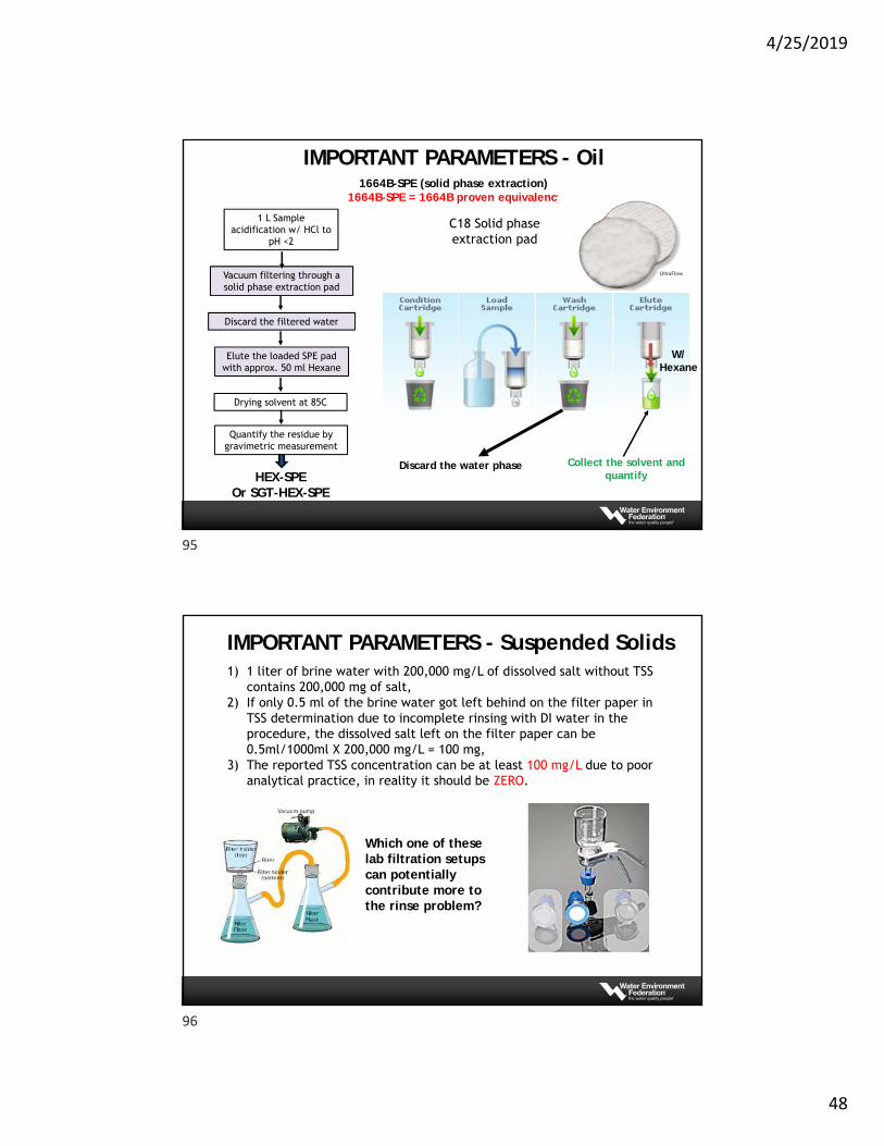
1664B-SPE (solid phase extraction) 1664B-SPE = 1664B proven equivalency
1 L Sample acidification w/ HCl to
pH <2
Vacuum filtering through a solid phase extraction pad
Drying solvent at 85C
Quantify the residue by gravimetric measurement
Discard the filtered water
C18 Solid phase extraction pad
Elute the loaded SPE pad with approx. 50 ml Hexane
HEX-SPEOr SGT-HEX-SPE
Collect the solvent and quantify
Discard the water phase
W/ Hexane
IMPORTANT PARAMETERS - Oil
IMPORTANT PARAMETERS - Suspended Solids1) 1 liter of brine water with 200,000 mg/L of dissolved salt without TSS
contains 200,000 mg of salt,2) If only 0.5 ml of the brine water got left behind on the filter paper in
TSS determination due to incomplete rinsing with DI water in the procedure, the dissolved salt left on the filter paper can be 0.5ml/1000ml X 200,000 mg/L = 100 mg,
3) The reported TSS concentration can be at least 100 mg/L due to poor analytical practice, in reality it should be ZERO.
Which one of these lab filtration setups can potentially contribute more to the rinse problem?
95
96
4/25/2019
49
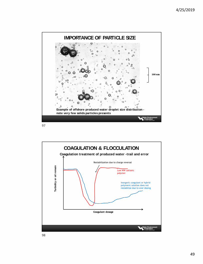
Example of offshore produced water droplet size distribution -note very few solids particles presents
IMPORTANCE OF PARTICLE SIZE
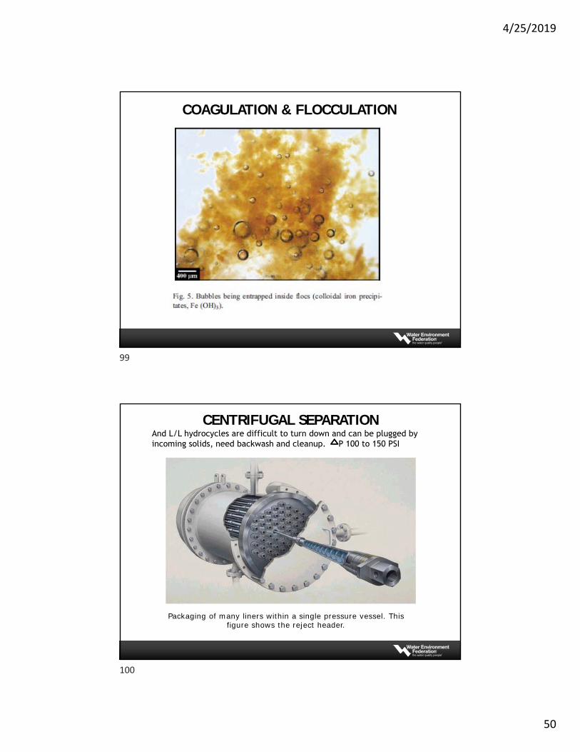
Turb
idit
y or
oil r
emai
n
Coagulant dosage
Low MW cationic polymer
Inorganic coagulant or hybrid polymeric solution does not restabilize due to over dosing
Restabilization due to charge reversal
Coagulation treatment of produced water -trail and error
COAGULATION & FLOCCULATION
97
98
4/25/2019
50
COAGULATION & FLOCCULATION
Hydrocyclones
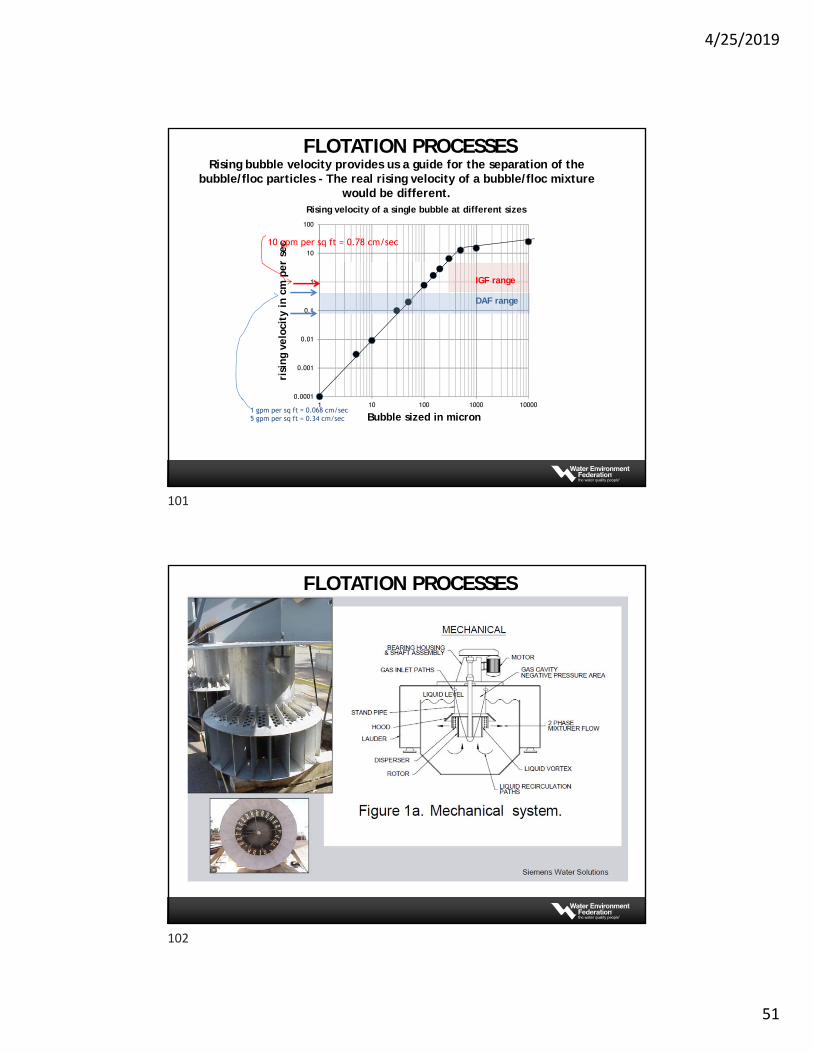
Packaging of many liners within a single pressure vessel. This figure shows the reject header.
And L/L hydrocycles are difficult to turn down and can be plugged by incoming solids, need backwash and cleanup. P 100 to 150 PSI
CENTRIFUGAL SEPARATION
99
100
4/25/2019
51
0.0001
0.001
0.01
0.1
1
10
100
1 10 100 1000 10000
risi
ng
velo
city
in c
m p
er s
ec
Bubble sized in micron
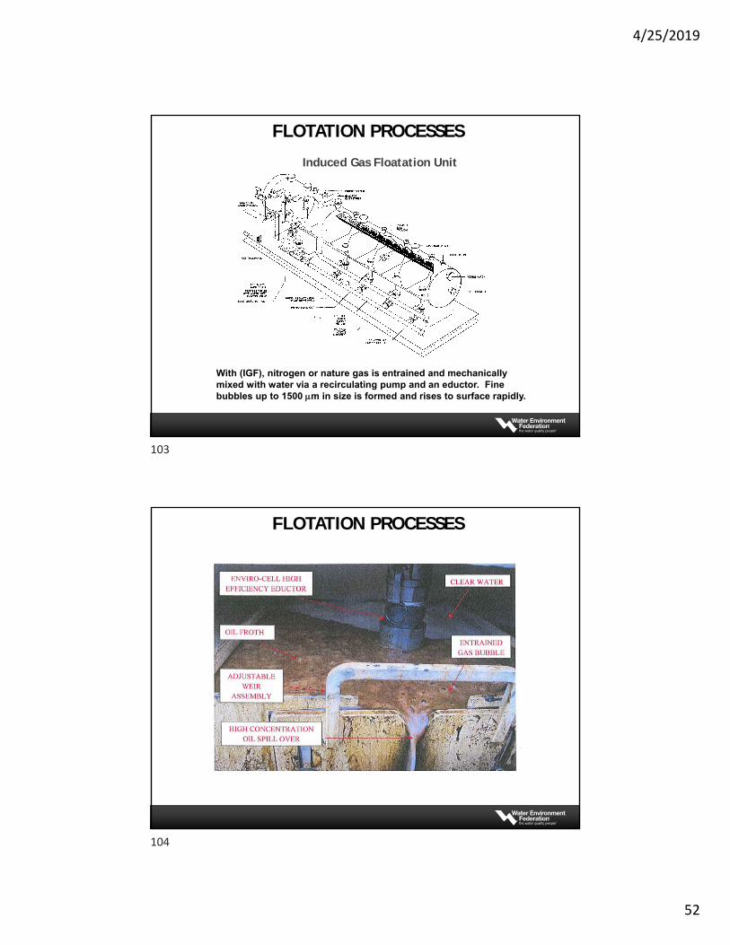
Rising velocity of a single bubble at different sizes
10 gpm per sq ft = 0.78 cm/sec
1 gpm per sq ft = 0.068 cm/sec5 gpm per sq ft = 0.34 cm/sec
DAF range
IGF range
Rising bubble velocity provides us a guide for the separation of the bubble/floc particles - The real rising velocity of a bubble/floc mixture
would be different.
FLOTATION PROCESSES
FLOTATION PROCESSES
101
102
4/25/2019
52
Induced Gas Floatation Unit
With (IGF), nitrogen or nature gas is entrained and mechanically mixed with water via a recirculating pump and an eductor. Fine bubbles up to 1500 m in size is formed and rises to surface rapidly.
FLOTATION PROCESSES
FLOTATION PROCESSES
103
104
4/25/2019
53
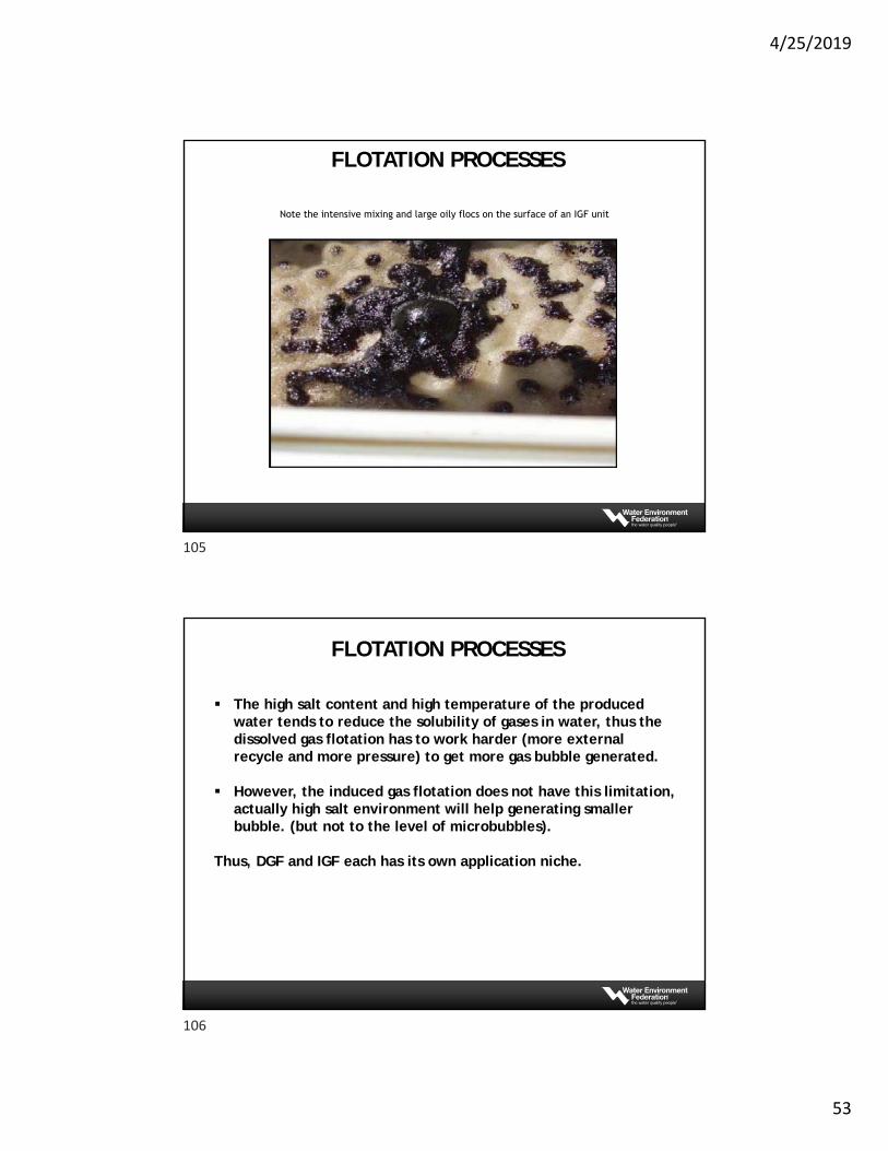
Note the intensive mixing and large oily flocs on the surface of an IGF unit
FLOTATION PROCESSES
The high salt content and high temperature of the produced water tends to reduce the solubility of gases in water, thus the dissolved gas flotation has to work harder (more external recycle and more pressure) to get more gas bubble generated.
However, the induced gas flotation does not have this limitation, actually high salt environment will help generating smaller bubble. (but not to the level of microbubbles).
Thus, DGF and IGF each has its own application niche.
FLOTATION PROCESSES
105
106
4/25/2019
54
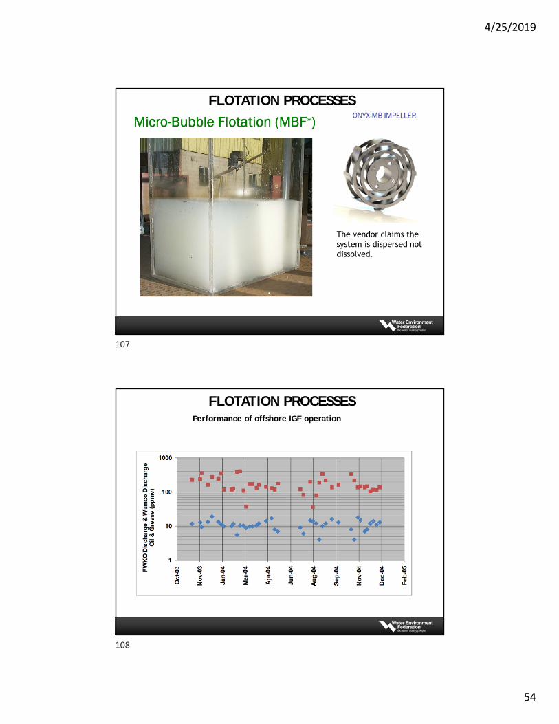
The vendor claims the system is dispersed not dissolved.
FLOTATION PROCESSES
Performance of offshore IGF operation
FLOTATION PROCESSES
107
108
4/25/2019
55
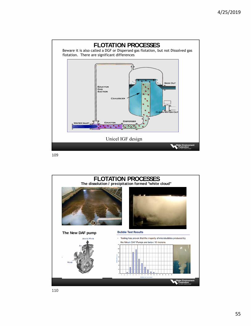
Unicel IGF design
Compact Vertical Flotation - Unicel:
Beware it is also called a DGF or Dispersed gas flotation, but not Dissolved gas flotation. There are significant differences
FLOTATION PROCESSES
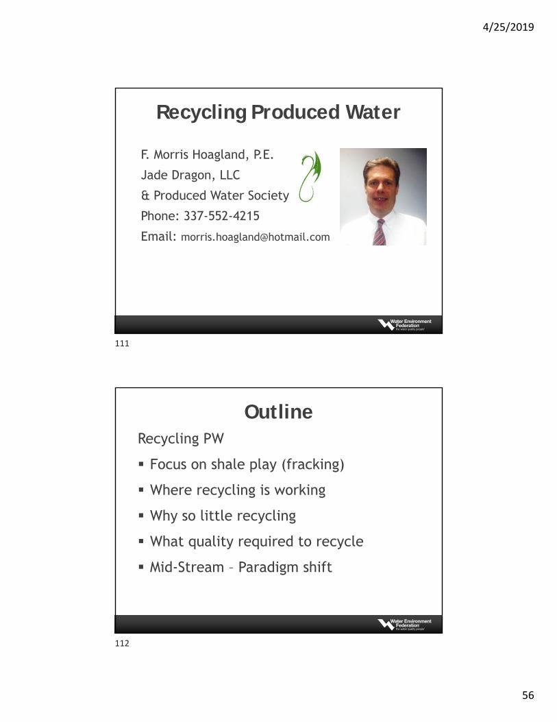
The dissolution / precipitation formed "white cloud"
The New DAF pump
FLOTATION PROCESSES
109
110
4/25/2019
56
F. Morris Hoagland, P.E.
Jade Dragon, LLC
& Produced Water Society
Phone: 337-552-4215
Email: [email protected]
Recycling Produced Water
OutlineRecycling PW
Focus on shale play (fracking)
Where recycling is working
Why so little recycling
What quality required to recycle
Mid-Stream – Paradigm shift
111
112
4/25/2019
57
Recycling Produced Water
Conventional wells water flood or overboard discharge
Primarily a shale play issue (unconventional wells) Some recycle Mostly disposal in SWD
Produced Water?Water produced in upstream – Produced Water?
Initially Flowback Water
First 3-4 weeks after completion (fracking)
• High flow rate drops quickly
• Highly contaminated
Longer term – Produced Water
• Natural formation water
• Primary contaminant is TDS
• Lower flow rates
113
114
4/25/2019
58
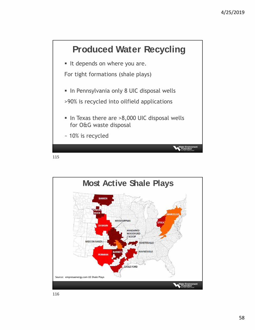
Produced Water Recycling It depends on where you are.
For tight formations (shale plays)
In Pennsylvania only 8 UIC disposal wells
>90% is recycled into oilfield applications
In Texas there are >8,000 UIC disposal wells for O&G waste disposal
~ 10% is recycled
Most Active Shale Plays
Source: empresaenergy.com US Shale Plays
115
116
4/25/2019
59
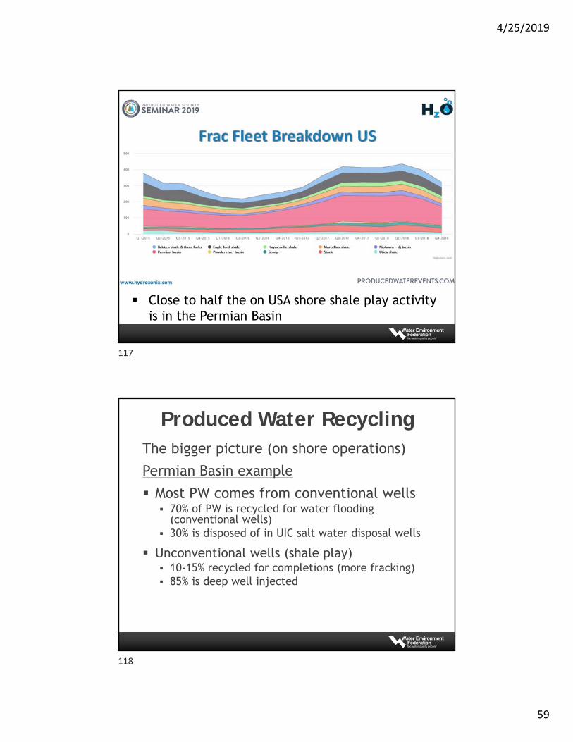
Close to half the on USA shore shale play activity is in the Permian Basin
Produced Water RecyclingThe bigger picture (on shore operations)
Permian Basin example
Most PW comes from conventional wells 70% of PW is recycled for water flooding
(conventional wells) 30% is disposed of in UIC salt water disposal wells
Unconventional wells (shale play) 10-15% recycled for completions (more fracking) 85% is deep well injected
117
118
4/25/2019
60
Produced Water RecyclingEarly fracking operations required fresh water
Innovative completion chemistry allows use of high TDS waters
Now often recycle is lower cost
Why not recycle more?
Easier to dispose of water in UIC (SWD) wells
Recycle requires more infrastructure and planning
Property owners want to sell their water to the operator
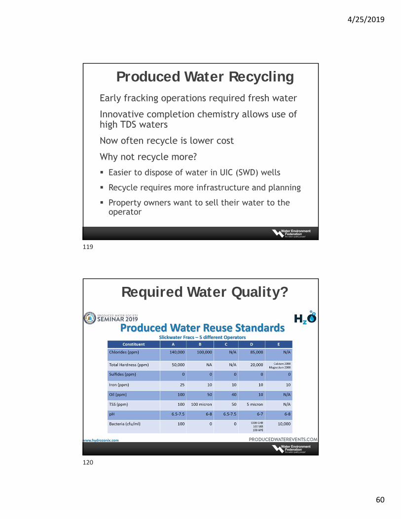
Required Water Quality?
119
120
4/25/2019
61
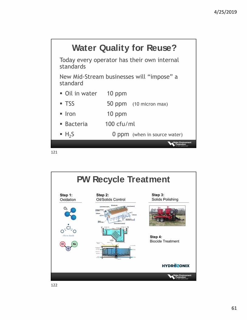
Water Quality for Reuse?Today every operator has their own internal standards
New Mid-Stream businesses will “impose” a standard
Oil in water 10 ppm
TSS 50 ppm (10 micron max)
Iron 10 ppm
Bacteria 100 cfu/ml
H2S 0 ppm (when in source water)
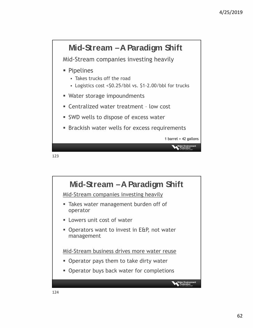
PW Recycle Treatment
Step 4:Biocide Treatment
121
122
4/25/2019
62
Mid-Stream – A Paradigm ShiftMid-Stream companies investing heavily
Pipelines Takes trucks off the road
Logistics cost <$0.25/bbl vs. $1-2.00/bbl for trucks
Water storage impoundments
Centralized water treatment – low cost
SWD wells to dispose of excess water
Brackish water wells for excess requirements
1 barrel = 42 gallons
Mid-Stream – A Paradigm ShiftMid-Stream companies investing heavily
Takes water management burden off of operator
Lowers unit cost of water
Operators want to invest in E&P, not water management
Mid-Stream business drives more water reuse
Operator pays them to take dirty water
Operator buys back water for completions
123
124
4/25/2019
63
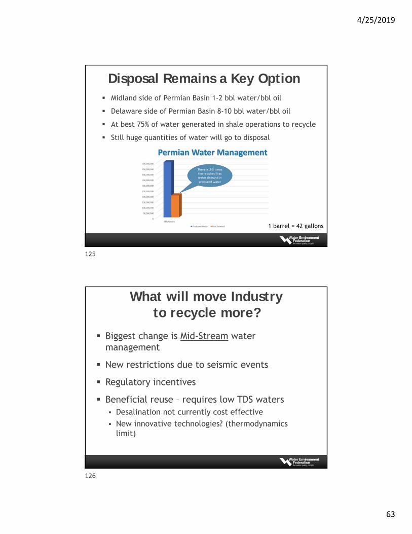
Disposal Remains a Key Option Midland side of Permian Basin 1-2 bbl water/bbl oil
Delaware side of Permian Basin 8-10 bbl water/bbl oil
At best 75% of water generated in shale operations to recycle
Still huge quantities of water will go to disposal
1 barrel = 42 gallons
What will move Industry to recycle more?
Biggest change is Mid-Stream water management
New restrictions due to seismic events
Regulatory incentives
Beneficial reuse – requires low TDS waters Desalination not currently cost effective
New innovative technologies? (thermodynamics limit)
125
126
4/25/2019
64
Appendix
Flowback Water Variable TDS (salts)
Polymers (raise viscosity)
Surfactants
Breakers (breaks up polymers)
Biocides
Proppant (sand and fines)
Shale fines
127
128
4/25/2019
65
Fluids used for Unconventional Wells Drilling Mud (water based and oil based)
Completion Brine (maintain pressure)
Stimulation Fluids (acids and solvents)
Hydraulic fracturing fluids Friction reducer Surfactants Biocides Breakers
Advanced Produced Water Treatment
F. Morris Hoagland, P.E.
Jade Dragon, LLC
& Produced Water Society
Phone: 337-552-4215
Email: [email protected]
129
130
4/25/2019
66
Outline
Advanced Treatment of Produced Water
Why use Advanced Treatment
Advanced Treatment Technologies
Conclusion
Treating Produced Water for Beneficial Reuse
Already reviewed conventional water treating Clean water for reuse/recycle in the oilfield Remaining TDS (salts) - water unsuitable outside
oilfield
Lots of technologies to remove TDS – all expensive Energy cost is primary barrier Exotic materials required - corrosion
Emerging technologies - closing the cost gap
131
132
4/25/2019
67
Treating Produced Water for Beneficial Reuse
Why is important to close this cost gap?
SWD (deep well injection) getting more expensive
Induced seismicity (i.e. Arbuckle – Oklahoma)
Over pressured disposal formations (i.e. San Andres – Permian)
Turn negative public perception into a positive perception
What is Goal of Advanced Treatment
Removal of dissolved salts required for reuse or discharge
Produce freshwater from the high saline FB/PW -residual concentrated brine water to disposal or further drying
Selection of desalination technology dependent on the salt concentration of the influent water
Courtesy: Paul Sun
133
134
4/25/2019
68
Four technologies making progress
Forward Osmosis
Membrane Distillation
Capacitance Deionization
Humidification Dehumidification
Treating Produced Water for Beneficial Reuse
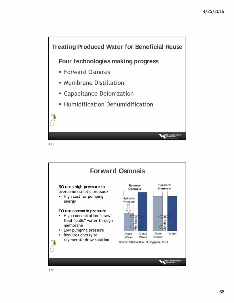
Forward Osmosis
RO uses high pressure to overcome osmotic pressure High cost for pumping
energy
FO uses osmotic pressure High concentration “draw”
fluid “pulls” water through membrane
Low pumping pressure Requires energy to
regenerate draw solution
135
136
4/25/2019
69
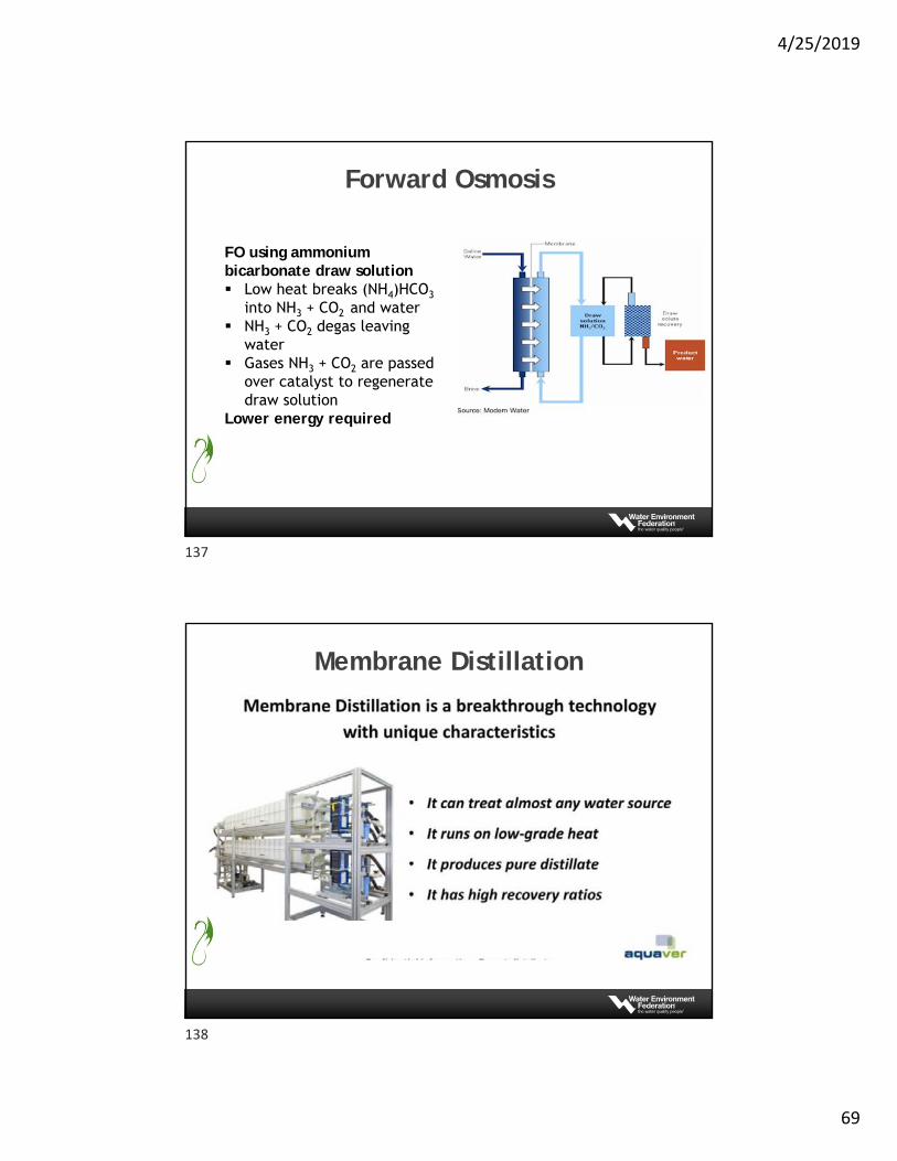
Forward Osmosis
FO using ammonium bicarbonate draw solution Low heat breaks (NH4)HCO3
into NH3 + CO2 and water NH3 + CO2 degas leaving
water Gases NH3 + CO2 are passed
over catalyst to regenerate draw solution
Lower energy required
Membrane Distillation
137
138
4/25/2019
70
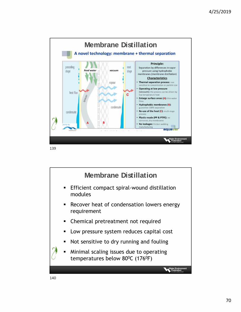
Membrane Distillation
Membrane Distillation
Efficient compact spiral-wound distillation modules
Recover heat of condensation lowers energy requirement
Chemical pretreatment not required
Low pressure system reduces capital cost
Not sensitive to dry running and fouling
Minimal scaling issues due to operating temperatures below 800C (1760F)
139
140
4/25/2019
71
Capacitive Deionization (CDI)
141
142
4/25/2019
72
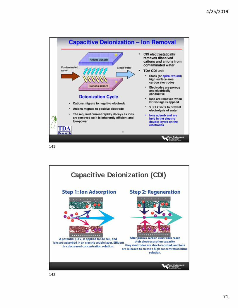
Capacitive Deionization (CDI)
Uses DC current to remove charged dissolved ions from water
Delivers deionized water suitable for surface discharge or other beneficial uses
Lower energy than thermal or vapor recompression processes
Requires pre-treatment to remove organics
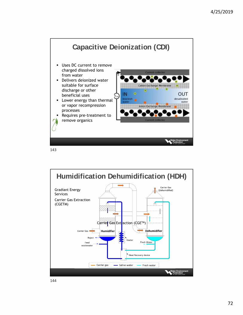
Humidification Dehumidification (HDH)
Gradiant Energy Services
Carrier Gas Extraction (CGETM)
Carrier Gas Extraction (CGETM)
143
144
4/25/2019
73
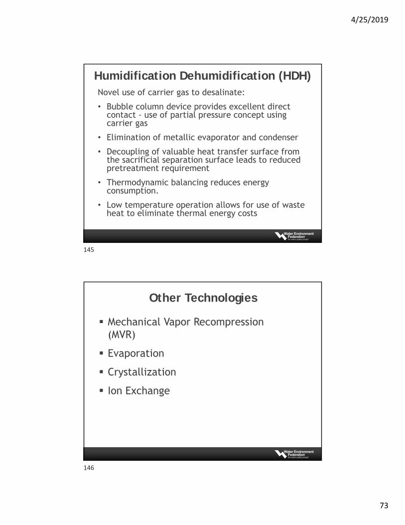
Novel use of carrier gas to desalinate:
• Bubble column device provides excellent direct contact - use of partial pressure concept using carrier gas
• Elimination of metallic evaporator and condenser
• Decoupling of valuable heat transfer surface from the sacrificial separation surface leads to reduced pretreatment requirement
• Thermodynamic balancing reduces energy consumption.
• Low temperature operation allows for use of waste heat to eliminate thermal energy costs
Humidification Dehumidification (HDH)
Other Technologies
Mechanical Vapor Recompression (MVR)
Evaporation
Crystallization
Ion Exchange
145
146
4/25/2019
74
Questions?
147
148
4/25/2019
75
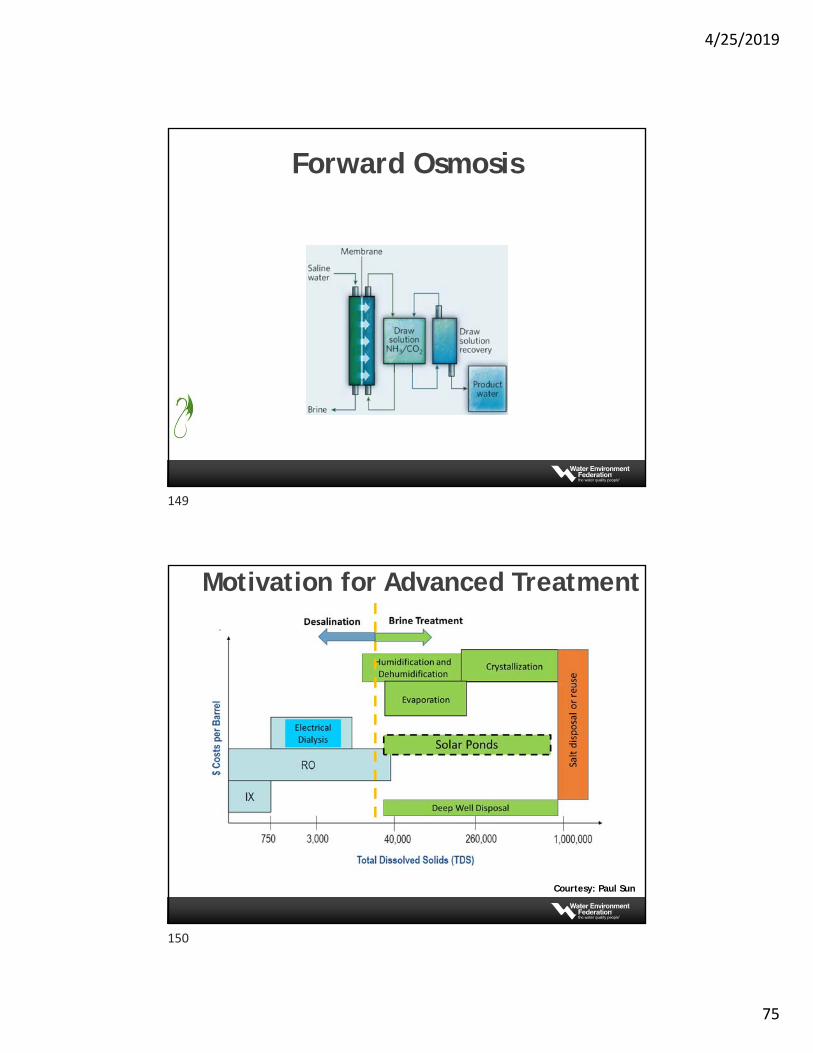
Forward Osmosis
Motivation for Advanced Treatment
Courtesy: Paul Sun
149
150
4/25/2019
76
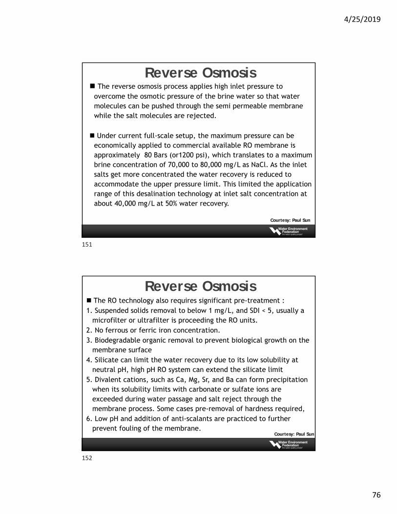
Reverse Osmosis
Courtesy: Paul Sun
The reverse osmosis process applies high inlet pressure to overcome the osmotic pressure of the brine water so that water molecules can be pushed through the semi permeable membrane while the salt molecules are rejected.
Under current full-scale setup, the maximum pressure can be economically applied to commercial available RO membrane is approximately 80 Bars (or1200 psi), which translates to a maximum brine concentration of 70,000 to 80,000 mg/L as NaCl. As the inlet salts get more concentrated the water recovery is reduced to accommodate the upper pressure limit. This limited the application range of this desalination technology at inlet salt concentration at about 40,000 mg/L at 50% water recovery.
Reverse Osmosis
Courtesy: Paul Sun
The RO technology also requires significant pre-treatment :1. Suspended solids removal to below 1 mg/L, and SDI < 5, usually a
microfilter or ultrafilter is proceeding the RO units.2. No ferrous or ferric iron concentration.3. Biodegradable organic removal to prevent biological growth on the
membrane surface4. Silicate can limit the water recovery due to its low solubility at
neutral pH, high pH RO system can extend the silicate limit5. Divalent cations, such as Ca, Mg, Sr, and Ba can form precipitation
when its solubility limits with carbonate or sulfate ions are exceeded during water passage and salt reject through the membrane process. Some cases pre-removal of hardness required,
6. Low pH and addition of anti-scalants are practiced to further prevent fouling of the membrane.
Courtesy: Paul Sun
151
152
4/25/2019
77
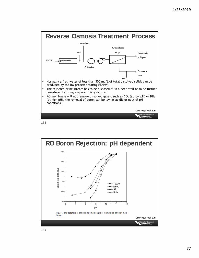
Reverse Osmosis Treatment Process
Courtesy: Paul Sun
Normally a freshwater of less than 500 mg/L of total dissolved solids can be produced by the RO process treating FB/PW,
The rejected brine stream has to be disposed of in a deep well or to be further dewatered by using evaporator/crystallizer.
RO membrane will not remove dissolved gases, such as CO2 (at low pH) or NH3(at high pH), the removal of boron can be low at acidic or neutral pH conditions.
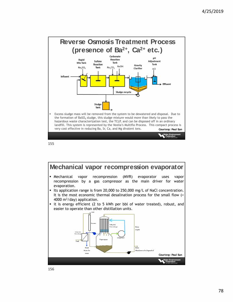
RO Boron Rejection: pH dependent
Courtesy: Paul Sun
153
154
4/25/2019
78
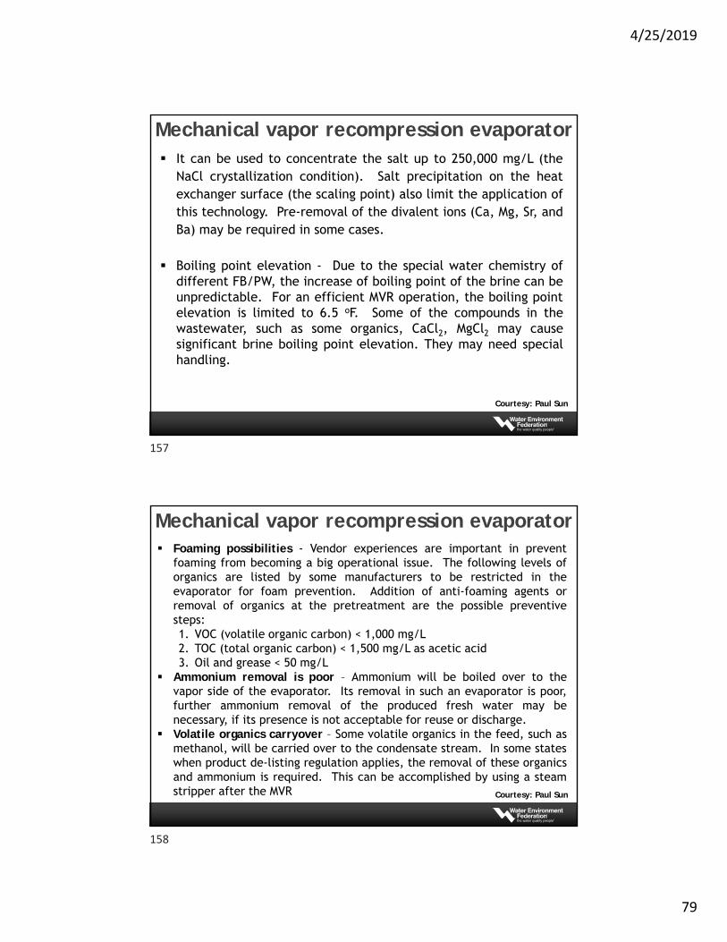
Reverse Osmosis Treatment Process (presence of Ba2+, Ca2+ etc.)
Courtesy: Paul Sun
Excess sludge mass will be removed from the system to be dewatered and disposal. Due to the formation of BaSO4 sludge, this sludge mixture would more than likely to pass the hazardous waste characterization test, the TCLP, and can be disposed off in an ordinary landfill. This system is represented by the Veolia’s Multiflo Process. This compact process is very cost effective in reducing Ba, Sr, Ca, and Mg divalent ions.
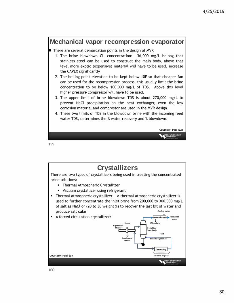
Mechanical vapor recompression evaporator
Courtesy: Paul Sun
Mechanical vapor recompression (MVR) evaporator uses vaporrecompression by a gas compressor as the main driver for waterevaporation.
Its application range is from 20,000 to 250,000 mg/L of NaCl concentration.It is the most economic thermal desalination process for the small flow (<4000 m3/day) application.
it is energy efficient (2 to 5 kWh per bbl of water treated), robust, andeasier to operate than other distillation units.
155
156
4/25/2019
79
Mechanical vapor recompression evaporator
Courtesy: Paul Sun
It can be used to concentrate the salt up to 250,000 mg/L (theNaCl crystallization condition). Salt precipitation on the heatexchanger surface (the scaling point) also limit the application ofthis technology. Pre-removal of the divalent ions (Ca, Mg, Sr, andBa) may be required in some cases.
Boiling point elevation - Due to the special water chemistry ofdifferent FB/PW, the increase of boiling point of the brine can beunpredictable. For an efficient MVR operation, the boiling pointelevation is limited to 6.5 oF. Some of the compounds in thewastewater, such as some organics, CaCl2, MgCl2 may causesignificant brine boiling point elevation. They may need specialhandling.
Mechanical vapor recompression evaporator
Courtesy: Paul Sun
Foaming possibilities - Vendor experiences are important in preventfoaming from becoming a big operational issue. The following levels oforganics are listed by some manufacturers to be restricted in theevaporator for foam prevention. Addition of anti-foaming agents orremoval of organics at the pretreatment are the possible preventivesteps:1. VOC (volatile organic carbon) < 1,000 mg/L2. TOC (total organic carbon) < 1,500 mg/L as acetic acid3. Oil and grease < 50 mg/L
Ammonium removal is poor – Ammonium will be boiled over to thevapor side of the evaporator. Its removal in such an evaporator is poor,further ammonium removal of the produced fresh water may benecessary, if its presence is not acceptable for reuse or discharge.
Volatile organics carryover – Some volatile organics in the feed, such asmethanol, will be carried over to the condensate stream. In some stateswhen product de-listing regulation applies, the removal of these organicsand ammonium is required. This can be accomplished by using a steamstripper after the MVR
157
158
4/25/2019
80
Mechanical vapor recompression evaporator
Courtesy: Paul Sun
There are several demarcation points in the design of MVR1. The brine blowdown Cl- concentration: 36,000 mg/L belong that
stainless steel can be used to construct the main body, above thatlevel more exotic (expensive) material will have to be used, increasethe CAPEX significantly
2. The boiling point elevation to be kept below 10F so that cheaper fancan be used for the recompression process, this usually limit the brineconcentration to be below 100,000 mg/L of TDS. Above this levelhigher pressure compressor will have to be used.
3. The upper limit of brine blowdown TDS is about 270,000 mg/L toprevent NaCl precipitation on the heat exchanger, even the lowcorrosion material and compressor are used in the MVR design.
4. These two limits of TDS in the blowdown brine with the incoming feedwater TDS, determines the % water recovery and % blowdown.
Crystallizers
Courtesy: Paul Sun
There are two types of crystallizers being used in treating the concentrated brine solutions:
Thermal Atmospheric Crystallizer Vacuum crystallizer using refrigerant
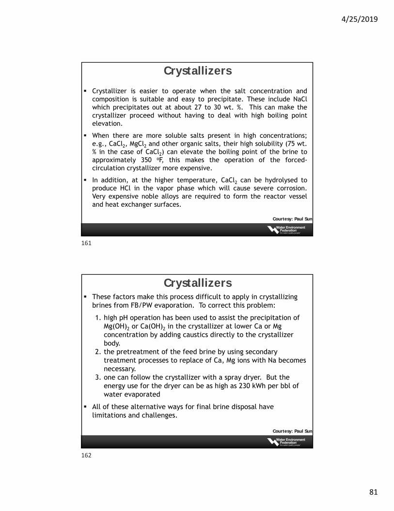
Thermal atmospheric crystallizer - a thermal atmospheric crystallizer is used to further concentrate the inlet brine from 200,000 to 300,000 mg/L of salt as NaCl or (20 to 30 weight %) to recover the last bit of water and produce salt cake
A forced circulation crystallizer:
159
160
4/25/2019
81
Crystallizers
Courtesy: Paul Sun
Crystallizer is easier to operate when the salt concentration andcomposition is suitable and easy to precipitate. These include NaClwhich precipitates out at about 27 to 30 wt. %. This can make thecrystallizer proceed without having to deal with high boiling pointelevation.
When there are more soluble salts present in high concentrations;e.g., CaCl2, MgCl2 and other organic salts, their high solubility (75 wt.% in the case of CaCl2) can elevate the boiling point of the brine toapproximately 350 oF, this makes the operation of the forced-circulation crystallizer more expensive.
In addition, at the higher temperature, CaCl2 can be hydrolysed toproduce HCl in the vapor phase which will cause severe corrosion.Very expensive noble alloys are required to form the reactor vesseland heat exchanger surfaces.
Crystallizers
Courtesy: Paul Sun
These factors make this process difficult to apply in crystallizing brines from FB/PW evaporation. To correct this problem:
1. high pH operation has been used to assist the precipitation of Mg(OH)2 or Ca(OH)2 in the crystallizer at lower Ca or Mg concentration by adding caustics directly to the crystallizer body.
2. the pretreatment of the feed brine by using secondary treatment processes to replace of Ca, Mg ions with Na becomes necessary.
3. one can follow the crystallizer with a spray dryer. But the energy use for the dryer can be as high as 230 kWh per bbl of water evaporated
All of these alternative ways for final brine disposal have limitations and challenges.
161
162
4/25/2019
82
Crystallizers
Courtesy: Paul Sun
Vacuum Crystallizers A newly developed low pressure and low temperature evaporator
by HPD of Veolia Water is targeting the highly soluble Ca or Mg chloride brine.
At low temperature, these chloride salts can precipitate out of solution at lower concentration. For example, CaCl2 solubility is 75 wt. % at 350 oF vs. 56 wt. % at 115 oF. At the lower concentration, the boiling point elevation is reduced from 135 to 56 oF. This makes the evaporation more economical if a deep vacuum can be applied to the crystallizer (0.5 psi).
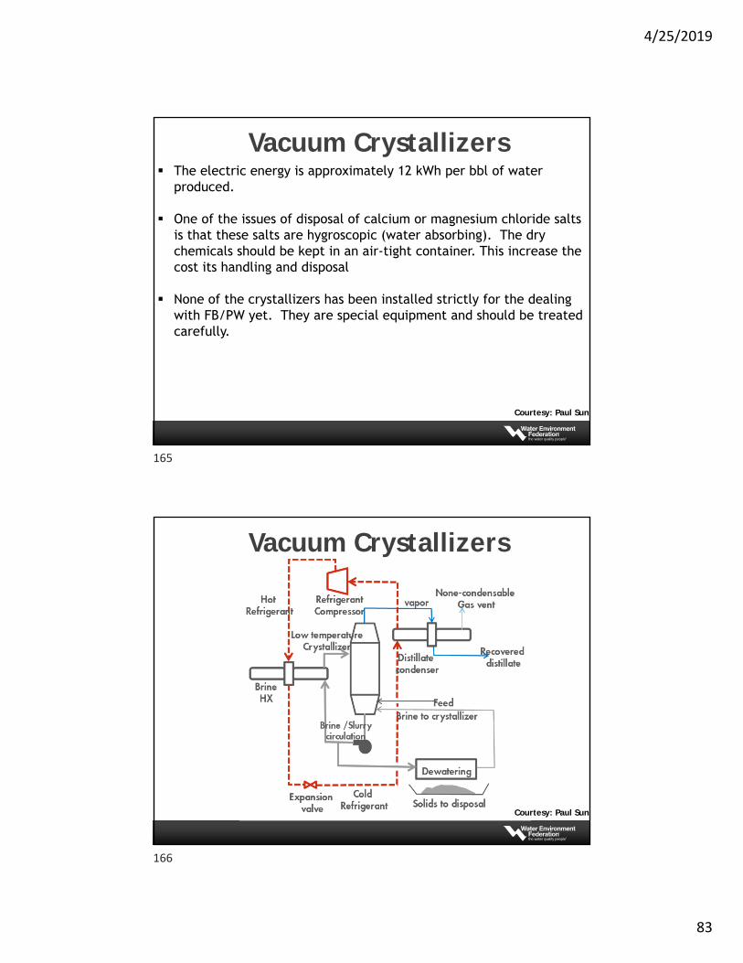
Next figure shows the schematics of a low temperature crystallizer. A closed loop heat pump employing a liquid refrigerant provides the cooling of the system and heating for evaporation at this low temperature, 130oF.
Courtesy: Paul Sun
163
164
4/25/2019
83
Vacuum Crystallizers The electric energy is approximately 12 kWh per bbl of water
produced.
One of the issues of disposal of calcium or magnesium chloride salts is that these salts are hygroscopic (water absorbing). The dry chemicals should be kept in an air-tight container. This increase the cost its handling and disposal
None of the crystallizers has been installed strictly for the dealing with FB/PW yet. They are special equipment and should be treated carefully.
Courtesy: Paul Sun
Vacuum Crystallizers
Courtesy: Paul Sun
165
166
4/25/2019
84
Deep Well Disposal
Courtesy: Paul Sun
Deep well disposal is usually the most cost-effective way for brine disposal. If it can be located safely and nearby.
Deep well location evaluation:1. Injection zone depth, confining geological structure, porosity,2. Injection zone geochemistry and groundwater chemistry, 3. Long term water storage capacity.4. Risk of inducing seismicity
Deep well injection is tightly regulated in the USA by EPA’s Underground Injection Control (UIC) Program to protect underground source of drinking water (TDS < 10,000 mg/L). One can inject brine into Class I or Class II wells.
Deep Well Disposal
Courtesy: Paul Sun
Class I well has injection zone below the lowermost formation containing a underground source of drinking water (USDW) within ¼ miles of the well bore.
Class II wells can receive oil and gas industry produced waters
The deep well construction is strictly regulated
The deep well is closely monitored for leakage or fracturing of receiving zone
However, once the restrictions are met, deep well can remove the brine permanently, and is economic to operate
167
168
4/25/2019
85
Deep Well Disposal
Courtesy: Paul Sun
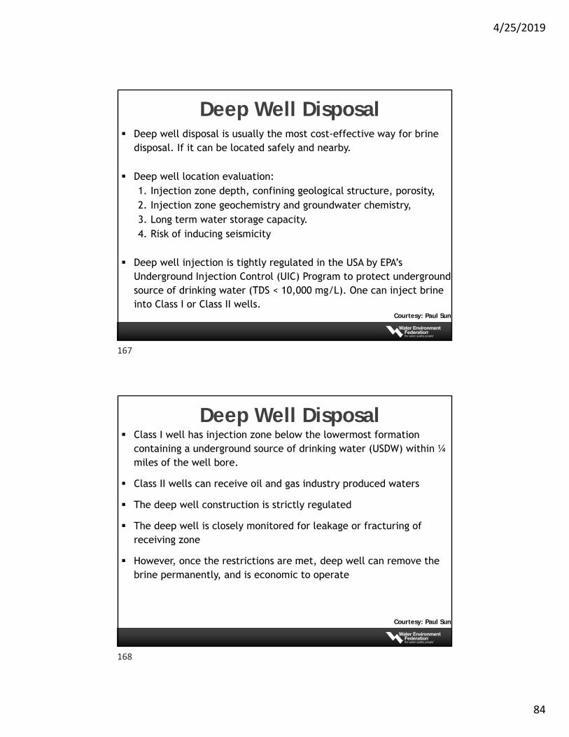
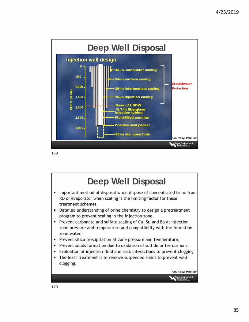
Groundwater Protection
Deep Well Disposal
Courtesy: Paul Sun
Important method of disposal when dispose of concentrated brine from RO or evaporator when scaling is the limiting factor for these treatment schemes,
Detailed understanding of brine chemistry to design a pretreatment program to prevent scaling in the injection zone,
Prevent carbonate and sulfate scaling of Ca, Sr, and Ba at injection zone pressure and temperature and compatibility with the formation zone water.
Prevent silica precipitation at zone pressure and temperature, Prevent solids formation due to oxidation of sulfide or ferrous ions, Evaluation of injection fluid and rock interactions to prevent clogging The least treatment is to remove suspended solids to prevent well
clogging.
169
170

4/25/2019
86
Questions?
171