Embed Size (px)
Citation preview

Fundamentals of Power Electronics Robert W Erickson University of Colorado Boulder, CO
SPRINGER-SCIENCE+BUSINESS MEDIA, B.V.

Cover design: Carolyn Walaitis
Copyright © 1997 by Springer Science+Business Media Dordrecht Originally published by Chapman & Hall in 1997
All rights reserved. l'io part of this book covered by the copyright hereon may be reproduced or used in any form or by any means-graphic, electronic, or mechanical, including photocopying, recording, taping, or information storage and retrieval systemswithout the written permssion of the publisher.
1 2 3 4 5 6 7 8 9 10 XXX 01 00 99 98 97
Library of Congress Cataloging-in-Publication Data
Erickson, Robert W (Robert Warren), Fundamentals of power electronics/Robert W Erickson. p. em. Includes Bibliographical references and index. ISBN 978-1-4615-7648-8 ISBN 978-1-4615-7646-4 (eBook) DOI 10.1007/978-1-4615-7646-4 !.Power electronics. I. Title TK7881. 15. E75 1997 62131'7--dc20 96-38347
CIP
British Library Cataloguing in Publication Data available
"Fudamentals of Power Electronics" is intended to present technically accurate and authoritative information from highly regared sources. The publisher, editors, advisers, and contributors have made every reasonable effort to ensure the accuracy of the information, but cannot assume responsibility for the accuracy of all information, or for the consequences of its use.

Fundamentals of Power Electronics

JOIN US ON THE INTERNET WWW: http://www.thomson.com
EMAIL: fmdit@kiosk. thomson. com thomson.com is the on-line portal for the products, services and resources available from
International Thomson Publishing (ITP). This Internet kiosk gives users immediate access to more than 34 ITP publishers and over 20,000 products. Through thomson. com
Internet users can search catalogs, examine subject-specific resource centers and subscribe to electronic discussions lists. You can purchase ITP products from your local
bookseller, or directly through thomson.com.
Visit Chapman & Hall's lnter.net Resource Center for information on our new publications, links to J useful sites on the World Wide Web and the opportunity to join our e-mail mailing list.
Point your browser to: http://www.chaphall.com or http://www.chaphall.com/chaphalllelecteng.html for Electrical Engineering
A service of I(f)P

Dedicated to
Linda and William
Robert Sr., Pearlie, and Karen

Contents
Dedication
Preface
v
XV
1.
I.
2.
3.
Introduction
1.1. Introduction to Power Processing 1.2. Several Applications of Power Electronics 1.3. Elements of Power Electronics References
Converters in Equilibrium
Principles of Steady-State Converter Analysis
1
1 8
10 11
13
15
2.1. Introduction 15 2.2. Inductor Volt-Second Balance, Capacitor Charge Balance, and the Small-Ripple
Approximation 17 2.3. Boost Converter Example 24 2.4. Cuk Converter Example 29 2.5. Estimating the Output Voltage Ripple in Converters Containing Two-Pole
Low-Pass Filters 34 2.6. Summary of Key Points 36 References 36 Problems 37
Steady-State Equivalent Circuit Modeling, Losses, and Efficiency
3.1. The de Transformer Model
vii
40
40

viii Contents
3.2. Inclusion of Inductor Copper Loss 3.3. Construction of Equivalent Circuit Model
3.3.1. Inductor Voltage Equation 3.3.2. Capacitor Current Equation 3.3.3. Complete Circuit Model 3.3.4. Efficiency
3.4. How to Obtain the Input Port of the Model 3.5. Example: Inclusion of Semiconductor Conduction Losses in the Boost
Converter Model 3.6. Summary of Key Points References Problems
43 46 47 47 48 49 51
53 57 58 58
4. Switch Realization 62
4.1. Switch Applications 64 4.1.1. Single-Quadrant Switches 64 4.1.2. Current-Bidirectional Two-Quadrant Switches 67 4.1.3. Voltage-Bidirectional Two-Quadrant Switch 70 4.1.4. Four-Quadrant Switches 71 4.1.5. Synchronous Rectifiers 73
4.2. A Brief Survey of Power Semiconductor Devices 74 4.2.1. Power Diodes 75 4.2.2. Metal-Oxide-Semiconductor Field-Effect Transistor (MOSFET) 78 4.2.3. Bipolar Junction Transistor (BJT) 82 4.2.4. Insulated Gate Bipolar Transistor (IGBT) 87 4.2.5. Thyristors (SCR, GTO, MCT) 89
4.3. Switching Loss 94 4.3.1. Transistor Switching with Clamped Inductive Load 94 4.3.2. Diode Recovered Charge 97 4.3.3. Device Capacitances, and Leakage, Package, and Stray Inductances 100 4.3.4. Efficiency vs. Switching Frequency 103
4.4. Summary of Key Points 104 References 105 Problems 106
5. The Discontinuous Conduction Mode 110
6.
5.1. Origin of the Discontinuous Conduction Mode, and Mode Boundary 5.2. Analysis of the Conversion Ratio M (D, K) 5.3. Boost Converter Example 5.4. Summary of Results and Key Points Problems
Converter Circuits
6.1. Circuit Manipulations 6.1.1. Inversion of Source and Load 6.1.2. Cascade Connection of Converters 6.1.3. Rotation of Three-Terminal Cell 6.1.4. Differential Connection of the Load
6.2. A Short List of Converters 6.3. Transformer Isolation
6.3.1. Full-Bridge and Half-Bridge Isolated Buck Converters 6.3.2. Forward Converter
Ill 115 121 127 129
135
136 136 138 141 142 146 150 154 159
Contents ix
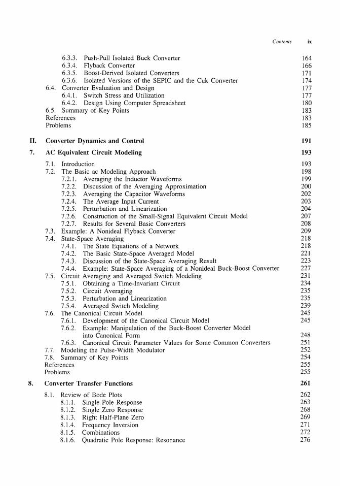
6.3.3. Push-Pull Isolated Buck Converter 164 6.3.4. Flyback Converter 166 6.3.5. Boost-Derived Isolated Converters 171 6.3 .6. Isolated Versions of the SEPIC and the Cuk Converter 17 4
6.4. Converter Evaluation and Design 177 6.4.1. Switch Stress and Utilization 177 6.4.2. Design Using Computer Spreadsheet 180
6.5. Summary of Key Points 183 References 183 Problems 185
II. Converter Dynamics and Control 191
193 7. AC Equivalent Circuit Modeling
8.
7 .1. Introduction 193 7.2. The Basic ac Modeling Approach 198
7 .2.1. Averaging the Inductor Waveforms 199 7.2.2. Discussion of the Averaging Approximation 200 7.2.3. Averaging the Capacitor Waveforms 202 7.2.4. The Average Input Current 203 7.2.5. Perturbation and Linearization 204 7.2.6. Construction of the Small-Signal Equivalent Circuit Model 207 7.2.7. Results for Several Basic Converters 208
7.3. Example: A Nonideal Flyback Converter 209 7.4. State-Space Averaging 218
7.4.1. The State Equations of a Network 218 7.4.2. The Basic State-Space Averaged Model 221 7.4.3. Discussion of the State-Space Averaging Result 223 7.4.4. Example: State-Space Averaging of a Nonideal Buck-Boost Converter 227
7.5. Circuit Averaging and Averaged Switch Modeling 231 7.5.1. Obtaining a Time-Invariant Circuit 234 7.5.2. Circuit Averaging 235 7.5.3. Perturbation and Linearization 235 7.5.4. Averaged Switch Modeling 239
7.6. The Canonical Circuit Model 245 7 .6.1. Development of the Canonical Circuit Model 245 7.6.2. Example: Manipulation of the Buck-Boost Converter Model
into Canonical Form 248 7.6.3. Canonical Circuit Parameter Values for Some Common Converters 251
7.7. Modeling the Pulse-Width Modulator 252 7.8. Summary of Key Points 254 References 255 Probkms ~5
Converter Transfer Functions
8.1. Review of Bode Plots 8.1.1. Single Pole Response 8.1.2. Single Zero Response 8.1.3. Right Half-Plane Zero 8.1.4. Frequency Inversion 8.1.5. Combinations 8.1.6. Quadratic Pole Response: Resonance
261
262 263 268 269 271 272 276

x Contents
8.1.7. The Low-Q Approximation 8.1.8. Approximate Roots of an Arbitrary-Degree Polynomial
8.2. Analysis of Converter Transfer Functions 8.2.1. Example: Transfer Functions of the Buck-Boost Converter 8.2.2. Transfer Functions of Some Basic CCM Converters 8.2.3. Physical Origins of the RHP Zero in Converters
8.3. Graphical Construction of Converter Transfer Functions 8.3.1. Series Impedances: Addition of Asymptotes 8.3.2. Parallel Impedances: Inverse Addition of Asymptotes 8.3.3. Another Example 8.3.4. Voltage Divider Transfer Functions: Division of Asymptotes
8.4. Measurement of AC Transfer Functions and Impedances 8.5. Summary of Key Points References Problems
9. Controller Design
282 285 289 289 292 294 296 296 296 303 307 309 314 315 315
323
9 .1. Introduction 323 9.2. Effect of Negative Feedback on the Network Transfer Functons 326
9.2.1. Feedback Reduces the Transfer Functions from Disturbances to the Output 327 9.2.2. Feedback Causes the Transfer Function from the Reference Input to the
Output to be Insensitive to Variations in the Gains in the Forward Path of the Loop 329
9.3. Construction of the Important Quantities 1 /(1 + D and T /(1 + D and the Closed-Loop Transfer Functions 329
9.4. Stability 332 9.4.1. The Phase Margin Test 333 9.4.2. The Relation Between Phase Margin and Closed-Loop Damping Factor 334 9.4.3. Transient Response vs. Damping Factor 338
9.5. Regulator Design 339 9.5.1. Lead (PD) Compensator 340 9.5.2. Lag (PI) Compensator 343 9.5.3. Combined (PID) Compensator 345 9.5.4. Design Example 346
9.6. Measurement of Loop Gains 355 9.6.1. Voltage Injection 357 9.6.2. Current Injection 359 9.6.3. Measurement of Unstable Systems 360
9.7. Summary of Key Points 361 References 361 Problems 362
10. Ac and de Equivalent Circuit Modeling of the Discontinuous Conduction Mode 369
10.1. DCM Averaged Switch Model 10.2. Small-Signal AC Modeling of the DCM Switch Network 10.3. Generalized Switch Averaging
10.3.1. DCM Buck Converter Example 10.3.2. Proof of Generalized Averaged Switch Modeling
10.4. Summary of Key Points References Problems
370 382 390 393 399 403 404 405

11. Current Programmed Control
11.1. Oscillation for D > 0.5 11.2. A Simple First-Order Model
11.2.1. Simple Model via Algebraic Approach: Buck-Boost Example 11.2.2. Averaged Switch Modeling
11.3. A More Accurate Model 11.3.1. Current Programmed Controller Model 11.3.2. Example: Analysis of CPM Buck Converter
11.4. Discontinuous Conduction Mode 11.5. Summary of Key Points References Problems
III. Magnetics
12. Basic Magnetics Theory
Contents xi
408
411 418 419 423 428 428 431 438 447 448 449
453
455
12.1. Review of Basic Magnetics 455 12.1.1. Basic Relationships 455 12.1.2. Magnetic Circuits 463
12.2. Transformer Modeling 466 12.2.1. The Ideal Transformer 467 12.2.2. The Magnetizing Inductance 468 12.2.3. Leakage Inductances 469
12.3. Loss Mechanisms in Magnetic Devices 471 12.3.1. Core Loss 471 12.3.2. Low-Frequency Copper Loss 474
12.4. Eddy Currents in Winding Conductors 474 12.4.1. The Skin Effect 475 12.4.2. The Proximity Effect 476 12.4.3. Magnetic Fields in the Vicinity of Winding Conductors: MMF Diagrams 479 12.4.4. Power Loss in a Layer 482 12.4.5. Example: Power Loss in a Transformer Winding 483 12.4.6. PWM Waveform Harmonics 487
12.5. Summary of Key Points 490 References 491 Problems 492
13. Filter Inductor Design 497
13.1. Several Types of Magnetic Devices, Their B-H Loops, and Core vs. Copper Loss 497 13.1.1. Filter Inductor 497 13.1.2. Ac Inductor 499 13.1.3. Transformer 500 13.1.4. Coupled Inductor 501 13.1.5. F1yback Transformer 502
13.2. Filter Inductor Design Constraints 503 13.2.1. Maximum Flux Density 506 13.2.2. Inductance 506 13.2.3. Winding Area 506 13.2.4. Winding Resistance 507
13.3. The Core Geometrical Constant K~ 507

xii Contents
13.4. A Step-by-Step Procedure 13.4.1. Procedure
13.5. Summary of Key Points References Problems
14. Transformer Design
14.1. Winding Area Optimization 14.2. Transformer Design: Basic Constraints
14.2.1. Core Loss 14.2.2. F1ux Density 14.2.3. Copper Loss 14.2.4. Total Power Loss vs Bmax
14.2.5. Optimum Flux Density 14.3. A Step-by-Step Transformer Design Procedure
14.3.1 Procedure 14.4. Examples
14.4.1. Example 1: Single-Output Isolated Cuk Converter 14.4.2. Example 2: Multiple-Output Full-Bridge Buck Converter
14.5. Ac Inductor Design 14.5.1. Outline of Derivation 14.5.2. Step-by-Step AC Inductor Design Procedure
14.6. Summary References Problems
IV. Modern Rectifiers and Power System Harmonics
15. Power and Harmonics in Nonsinusoidal Systems
15.1. Average Power 15.2. Root-Mean-Square (RMS) Value of a Waveform 15.3. Power Factor
15.3.1. Linear Resistive Load, Nonsinusoidal Voltage 15.3.2. Nonlinear Dynamical Load, Sinusoidal Voltage
15.4. Power Phasors in Sinusoidal Systems 15.5. Harmonic Currents in Three-Phase Systems
15.5.1. Harmonic Currents in Three-Phase Four-Wire Networks 15.5.2. Harmonic Currents in Three-Phase Three-Wire Networks 15.5.3. Harmonic Current F1ow in Power Factor Correction Capacitors
15.6. AC Line Current Harmonic Standards 15.6.1. US MIL-STD-461B 15.6.2. International Electrotechnical Commission Standard 555 15.6.3. IEEE/ANSI Standard 519
References Problems
16. Line-Commutated Rectifiers
16.1. The Single-Phase Full-Wave Rectifier 16.1.1. Continuous Conduction Mode 16.1.2. Discontinuous Conduction Mode
508 509 509 510 510
512
513 517 518 518 519 520 520 521 522 524 524 528 531 532 533 534 535 535
539
541
542 543 546 546 547 550 551 552 553 554 555 556 556 557 559 559
562
562 563 564

16.1.3. Behavior When Cis Large 16.1.4. Minimizing THD When Cis Small
16.2. The Three-Phase Bridge Rectifier 16.2.1. Continuous Conduction Mode 16.2.2. Discontinuous Conduction Mode
16.3. Phase Control 16.3.1. Inverter Mode 16.3.2. Harmonics and Power Factor 16.3.3. Commutation
16.4. Harmonic Trap Filters 16.5. Transformer Connections 16.6. Summary References Problems
17. The Ideal Rectifier
17 .1. Properties of the Ideal Rectifier 17 .2. Realization of a Near-Ideal Rectifier 17.3. Single-Phase Converter Systems Incorporating Ideal Rectifiers 17.4. RMS Values of Rectifier Waveforms
17 .4.1. Boost Rectifier Example 17.4.2. Comparison of Single-Phase Rectifier Topologies
17.5. Ideal Three-Phase Rectifiers 17.5.1. Three-Phase Rectifiers Operating in CCM 17.5.2. Some Other Approaches to Three-Phase Rectification
17.6. Summary of Key Points References Problems
Contents xiii
565 566 568 569 569 570 572 573 573 575 582 583 585 586
590
590 593 599 604 605 608 608 611 615 622 622 624
18. Low Harmonic Rectifier Modeling and Control 627
18.1. Modeling Losses and Efficiency in CCM High-Quality Rectifiers 627 18.1.1. Expression for Controller Duty Cycle d (t) 628 18.1.2. Expression for the de Load Current 629 18.1.3. Solution for Converter Efficiency 7J 632 18.1.4. Design Example 634
18.2. Controller Schemes 634 18.2.1. Average Current Control 634 18.2.2. Feedforward 635 18.2.3. Current Programmed Control 636 18.2.4. Hysteretic Control 639 18.2.5. Nonlinear Carrier Control 641
18.3. Control System Modeling 645 18.3.1. Modeling the Outer Low-Bandwidth Control System 645 18.3.2. Modeling the Inner Wide-Bandwidth Average Current Controller 650
18.4. Summary of Key Points 652 References 652 Problems 653
V. Resonant Converters 657
19. Resonant Conversion 659
19.1. Sinusoidal Analysis of Resonant Converters 664

xiv Contents
19.1.1. Controlled Switch Network Model 664 19.1.2. Modeling the Rectifier and Capacitive Filter Networks 666 19.1.3. Resonant Tank Network 668 19.1.4. Solution of Converter Voltage Conversion Ratio M = V /Vg 670
19.2. Examples 670 19.2.1. Series Resonant de-de Converter Example 670 19.2.2. Subharmonic Modes of the Series Resonant Converter 673 19.2.3. Parallel Resonant de-de Converter Example 674
19.3. Exact Characteristics of the Series and Parallel Resonant Converters 678 19.3.1. Series Resonant Converter 679 19.3.2. Parallel Resonant Converter 686
19.4. Soft Switching 689 19.4.1. Operation of the Full Bridge Below Resonance: Zero Current Switching 690 19.4.2. Operation of the Full Bridge Above Resonance: Zero Voltage Switching 692 19.4.3. The Zero Voltage Transition Converter 695
19.5. Load-Dependent Properties of Resonant Converters 697 19.5.1. Inverter Output Characteristics 699 19.5.2. Dependence of Transistor Current on Load 699 19.5.3. Dependence of the ZVS{ZCS Boundary on Load Resistance 702
19.6. Summary of Key Points 705 References 705 Problems 707
20. Quasi-Resonant Converters
20.1. . The Zero-Current-Switching Quasi-Resonant Switch Cell 20.1.1. Waveforms of the Half-Wave ZCS Quasi-Resonant Switch Cell 20.1.2. The Average Terminal Waveforms 20.1.3. The Full-Wave ZCS Quasi-Resonant Switch Cell
20.2. Resonant Switch Topologies 20.2.1. The Zero-Voltage-Switching Quasi-Resonant Switch 20.2.2. The Zero-Voltage-Switching Multi-Resonant Switch 20.2.3. Quasi-Square-Wave Resonant Switches
20.3. AC Modeling of Quasi-Resonant Converters 20.4. Summary of Key Points References Problems
Appendices
Appendix 1. RMS Values of Commonly-Observed Converter Waveforms
A 1.1. Some Common Waveforms Al.2. General Piecewise Waveform
Appendix 2. Magnetics design tables
A2.1. Pot core data A2.2. EE core data A2.3. EC core data A2.4. ETD core data A2.5. PQ core data A2.6. American wire gauge data References
Appendix 3. Averaged Switch Modeling of a CCM SEPIC
Index
711
712 714 718 723 724 726 729 730 732 737 737 738
741 743 743 747
751 752 753 754 754 755 755 756
757 763
Preface
In many university curricula, the power electronics field has evolved beyond the status of comprising one or two special-topics courses. Often there are several courses dealing with the power electronics field, covering the topics of converters, motor drives, and power devices, with possibly additional advanced courses in these areas as well. There may also be more traditional power-area courses in energy conversion, machines, and power systems. In the breadth vs. depth tradeoff, it no longer makes sense for one textbook to attempt to cover all of these courses; indeed, each course should ideally employ a dedicated textbook.
This text is intended for use in introductory power electronics courses on converters, taught at the senior or first-year graduate level. There is sufficient material for a one year course or, at a faster pace with some material omitted, for two quarters or one semester.
The first class on converters has been called a way of enticing control and electronics students into the power area via the "back door". The power electronics field is quite broad, and includes fundamentals in the areas of
• Converter circuits and electronics
• Control systems
• Magnetics
• Power applications
• Design-oriented analysis
This wide variety of areas is one of the things which makes the field so interesting and appealing to newcomers. This breadth also makes teaching the field a challenging undertaking, because one cannot assume that all students enrolled in the class have solid prerequisite knowledge in so many areas. Indeed, incoming students may have individual backgrounds in the power, control, or electronics
XV
xvi Preface
areas, but rarely in all three. Yet it is usually desired to offer the class to upper-division undergraduate and entering graduate students.
Hence, in teaching a class on converters (and in writing a textbook), there are two choices:
1. Avoid the problem of prerequisites, by either (a) assuming that the students have all of the prerequisites and discussing the material at a high level (suitable for an advanced graduate class), or (b) leaving out detailed discussions of the various contributing fields.
2. Attack the problem directly, by teaching or reviewing material from prerequisite areas as it is needed. This material can then be directly applied to power electronics examples. This approach is suitable for a course in the fourth or fifth year, in which fundamentals are stressed.
Approach (2) is employed here. Thus, the book is not intended for survey courses, but rather, it treats fundamental concepts and design problems in sufficient depth that students can actually build converters. An attempt is made to deliver specific results. Completion of core circuits and electronics courses is the only prerequisite assumed; prior knowledge in the areas of magnetics, power, and control systems is helpful but not required.
In the power electronics literature, much has been made of the incorporation of other disciplines such as circuits, electronic devices, control systems, magnetics, and power applications, into the power electronics field. Yet the field has evolved, and now is more than a mere collection of circuits and applications linked to the fundamentals of other disciplines. There is a set of fundamentals that are unique to the field of power electronics. It is important to identify these fundamentals, and to explicitly organize our curricula, academic conferences, and other affairs around these fundamentals. This book is organized around the fundamental principles, while the applications and circuits are introduced along the way as examples.
A concerted effort is made to teach converter modeling. Fundamental topics covered include:
Fundamentals of PWM converter analysis, including the principles of inductor volt-second balance and capacitor charge balance, and the small-ripple approximation (Chapter 2).
Converter modeling, including the use of the de transformer model, to predict efficiency and losses (Chapter 3).
Realization of switching elements using semiconductor devices. One-, two-. and four-quadrant switches. A brief survey of power semiconductor devices (Chapter 4).
An up-to-date treatment of switching losses and their origins. Diode stored charge, device capacitances, and ringing waveforms (Chapter 4).
Origin and steady-state analysis of the discontinuous conduction mode (Chapter 5).
Converter topologies (Chapter 6).
The use of averaging to model converter small-signal ac behavior. Averaged switch modeling (Chapter 7).
Converter small-signal ac transfer functions, including the origins of resonances and right half-plane zeroes. Control-to-output and line-to-output transfer functions, and output impedance (Chapter 8).
A basic discussion of converter control systems, including objectives, the system block diagram. and the effect of feedback on converter behavior (Chapter 9).
Ac modeling of the discontinuous conduction mode. Quantitative behavior of DCM small-signal transfer functions (Chapter 10).
Current-programmed control. Oscillation for D > 0.5. Equivalent circuit modeling (Chapter II).
Basic magnetics. including inductor and transformer modeling, and loss mechanisms in high-frequency power magnetics (Chapter 12).
An understanding of what determines the size of power inductors and transformers. Power inductor and transformer design issues (Chapters 13 and 14 ).
Harmonics in power systems (Chapter 15).

Preface xvii
A modem viewpoint of rectifiers, including harmonics, power factor, and mitigation techniques in conventional rectifiers, and operation of sophisticated low-harmonic rectifiers (Chapters 16-18).
Analysis and modeling of low-harmonic rectifiers (Chapters 17-18).
Resonant inverters and de-de converters: approximate analysis techniques, characteristics of basic converters, and load-dependent properties (Chapter 19).
Zero voltage switching, zero current switching, and the zero-voltage-transition converter (Chapter 19).
Resonant switch converters, including basic operation, efficiency and losses, and ac modeling (Chapter 20).
On teaching averaged converter modeling: I think that this is one of the important fundamentals of the field, and hence we should put serious effort into teaching it. Although we in the academic community may debate how to rigorously justify averaging, nonetheless it is easy to teach the students to average: Just average all of the waveforms over one switching period. In particular, for the continuous conduction mode, average the inductor voltages and capacitor currents over one switching period, ignoring the ripple. That's all that is required, and I have found that students quickly and easily learn to average waveforms. The results are completely general, they aren't limited to SPDT switches, and they can easily be used to refine the model by inclusion of losses, dynamics, and control variations. To model dynamics, it is also necessary to linearize the resulting equations. But derivation of small-signal models is nothing new to the students -they have already seen this in their core electronics classes, as well as in numerous math courses and perhaps also in energy conversion. It isn't necessary to teach full-blown state-space averaging, but I have included an optional (with asterisk) section on this for the graduate students. I personally prefer to initially skip Sections 7.4 and 7.5. After covering Chapters 8 and 9, I return to cover Sections 7.4 and 7.5 before teaching Chapters 10 and 11.
Averaging aside, it is also important to teach modeling in a pedagogically sound way. The object is to describe the important properties of the converter, in a simple and clear way. The de transformer represents the basic function of a de-de converter, and so the modeling process should begin with a de transformer having a turns ratio equal to the conversion ratio of the converter. For example, the model of the buck-boost converter ought to contain a buck transformer cascaded by a boost transformer, or perhaps the two transformers combined into a single D: D' transformer. This first-order model can later be refined if desired, by addition of loss elements, dynamic elements, etc.
The design-oriented analysis methods of R. D. Middlebrook have been well accepted by a significant portion of the power electronics community. While the objective of this text is the introduction of power electronics rather than design-oriented analysis, the converter analyses and examples are nonetheless done in a design-oriented way. Approximations are often encouraged, and several of the techniques of design-oriented analysis are explicitly taught in parts of Chapters 8 and 9. We need to teach our students how to apply our academic theory to real-world, and hence complicated, problems. Design-oriented analysis is the missing linlc
Chapter 8 contains a "review" of Bode diagrams, including resonant responses and right half-plane zeroes. Also included is material on design-oriented analysis, in the context of converter transfer functions. The Bode diagram material is covered in more depth than in prerequisite classes. I have found that the material of Chapter 8 is especially popular with continuing education students who are practicing engineers. I recommend at least quickly covering this chapter in lecture. Those instructors who choose to skip some or all of Chapter 8 can assign it as reading, and hold students responsible for the material. In a similar manner, Chapter 9 contains a "review" of classical control systems, in the context of switching regulators. This chapter explicitly makes the connection between the smallsignal converter models derived in other chapters, and their intended application. Many power area students are unfamiliar with this material, and even control-area students comment that they learned something from the design-oriented approach.
xviii Preface
Parts III, IV, and V can be covered in any order. Part III includes a review of basic magnetics, a discussion of proximity loss, and an introduction to the issues governing design of magnetic devices. The inclusion of step-by-step design procedures may be somewhat controversial; however, these procedures explicitly illustrate the issues inherent in magnetics design. Student tendencies towards cookbook mentality are mitigated by the inclusion of homework problems which cannot be solved using the given step-by-step procedures. Part IV, entitled "Modern rectifiers," covers the issues of power system harmonics, generation of harmonics by conventional rectifiers, and low-harmonic rectifiers. Chapters 17 and 18 cover low-harmonic rectifiers in depth, including converter analysis and modeling, and rectifier control systems. Resonant converters are treated in Part V. There have been a tremendous number of papers written on resonant converters, most of which are very detailed and complicated. Indeed, the complexity of resonant converter behavior makes it challenging to teach this subject in depth. Two somewhat introductory chapters are included here. State-plane analysis is omitted, and is left for an advanced graduate class. In Chapter 19, resonant inverters and de-de converters are introduced and are analyzed via the sinusoidal approximation. Soft switching is described, in the context of both resonant converters and the zero-voltage transition converter. Some resonant network theorems are also presented, which yield insight into the design of resonant inverters with reduced circulating currents, with zero-voltage switching over a wide range of load currents, and with desired output characteristics. Resonant switch converters are introduced and modeled in Chapter 20.
Most chapters include both short analysis problems, and longer analysis and/or design problems. References are given at the end of each chapter; these are not intended to be exhaustive bibliographies, but rather are a starting place for additional reading.
This text has evolved from course notes developed over thirteen years of teaching power electronics at the University of Colorado, Boulder. These notes, in turn, were heavily influenced by my previous experience as a graduate student at the California Institute of Technology, under the direction of Profs. Slobodan Cuk and R. D. Middlebrook, to whom I am grateful. In addition, I appreciate the numerous helpful technical discussions and suggestions of my colleague at the University of Colorado, Prof. Dragan Maksimovic. I would also like to thank the following individuals for their suggestions: Prof. Arthur Witulski (University of Arizona, Tucson), Prof. Sigmund Singer (Tel-Aviv University, Israel), Dr. Michael Madigan, and Carlos Oliveira.
ROBERT W. ERICKSON
Boulder, Colorado