Embed Size (px)
Citation preview
4/11/2007 ١
Fundamentals of Object-
Oriented Analysis and Design
Advanced Software Engineering
Ali Kamandi
Sharif University of Technology
March 2007
4/11/2007 ٢
Introduction
� Object-Oriented analysis is based upon
concepts that we first learned in kindergarten:
objects and attributes, classes and members,
wholes and parts.
[Coad & Yourdon 1991]
4/11/2007 ٣
Introduction
� To define all classes, the operations, the attributes, the relationships and the behavior the following tasks must be
done:
� Basic user requirements must be communicated
between the customer and the software engineer.
� Classes must be identified.
� A class hierarchy must be specified.
� Object to object relationships should be represented.
� Object behavior must be modeled.
� Above Tasks must be reapplied iteratively until the
model is complete.
4/11/2007 �
OO analysis and design methods
� Coad and Yourdon
� Booch method OOSE
� OMT
� RDD
� The Wirfs-Brock method (do not make
clear distinction between design and
analysis tasks)
4/11/2007 �
Coad and Yourdon
� Analysis process: five layers (1989)� Finding classes
� Identifying structures (Gen-Spec, Whole-Part)
� Identifying subjects (subsystems)
� Defining attributes
� Defining services (operations)
� Design process: four components (1991)� Problem domain Component
� Human Interaction Component� Task Management Component
� Data Management Component
� Simplcity of notation
4/11/2007 �
Booch method
� Design method (1991) , analysis method
(1994)
� Design process: Incremental design
� Macro Process & Micro Peocess
� Notation: rich in symbols.
� Discussion: complicated notation
4/11/2007 ٧
OOSE
� Jacobson 1992 (Objectory 1987)
� Full lifecycle
� Analysis
� requirement analysis, robustness analysis
� Use Case Model, Domain Object Model, Interface Description
� Construction: design & implementation
� Testing
4/11/2007 ٨
OMT (Rumbaugh 1991)
� The process: three phase (analysis, system design and object design)
� Object Model (Object classes & their relationships)
� Dynamic Model: Event-Trace diagram & state-chart diagram)
� Functional Model: Data Flow Diagram (DFD)
� Pragmatic: OMTool. Published text.
� Discussion: place more emphasis on specifying what an object is rather than how it is used.
4/11/2007 ٩
OOA- A Generic View
• define use cases
• extract candidate classes
• establish basic class relationships
• define a class hierarchy
• identify attributes for each class
• specify methods that service the attributes
• indicate how classes/objects are related
• build a behavioral model
• iterate on the first five steps
4/11/2007 ١٠
4/11/2007 ١١
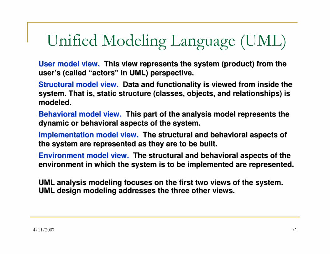
Unified Modeling Language (UML)
User model view.User model view. This view represents the system (product) from the This view represents the system (product) from the
useruser’’s (called s (called ““actorsactors”” in UML) perspective.in UML) perspective.
Structural model view.Structural model view. Data and functionality is viewed from inside the Data and functionality is viewed from inside the
system. That is, static structure (classes, objects, and relatiosystem. That is, static structure (classes, objects, and relationships) is nships) is
modeled.modeled.
Behavioral model view.Behavioral model view. This part of the analysis model represents the This part of the analysis model represents the
dynamic or behavioral aspects of the system. dynamic or behavioral aspects of the system.
Implementation model view.Implementation model view. The structural and behavioral aspects of The structural and behavioral aspects of
the system are represented as they are to be built.the system are represented as they are to be built.
Environment model view.Environment model view. The structural and behavioral aspects of the The structural and behavioral aspects of the
environment in which the system is to be implemented are represeenvironment in which the system is to be implemented are represented.nted.
UML analysis modeling focuses on the first two views of the systUML analysis modeling focuses on the first two views of the system.em.UML design modeling addresses the three other views.UML design modeling addresses the three other views.
4/11/2007 ١٢
Domain Analysis� OOA at the business area level called Domain Analysis.
� Domain Analysis is performed to create a library of reusable classes applicable to an entire category of applications.
� Using a robust class library produces the system faster, cheaper and more reliable.
� But where did such a library come from? By applying domain analysis.
4/11/2007 ١٣
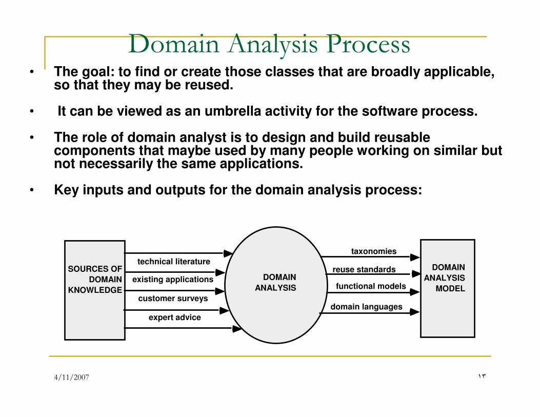
Domain Analysis Process
DOMAIN
ANALYSIS
SOURCES OF
DOMAIN
KNOWLEDGE
DOMAIN
ANALYSIS
MODEL
technical literature
existing applications
customer surveys
expert advice
current/future requirements
class taxonomies
reuse standards
functional models
domain languages
• The goal: to find or create those classes that are broadly applicable, so that they may be reused.
• It can be viewed as an umbrella activity for the software process.
• The role of domain analyst is to design and build reusable components that maybe used by many people working on similar butnot necessarily the same applications.
• Key inputs and outputs for the domain analysis process:
4/11/2007 ١�
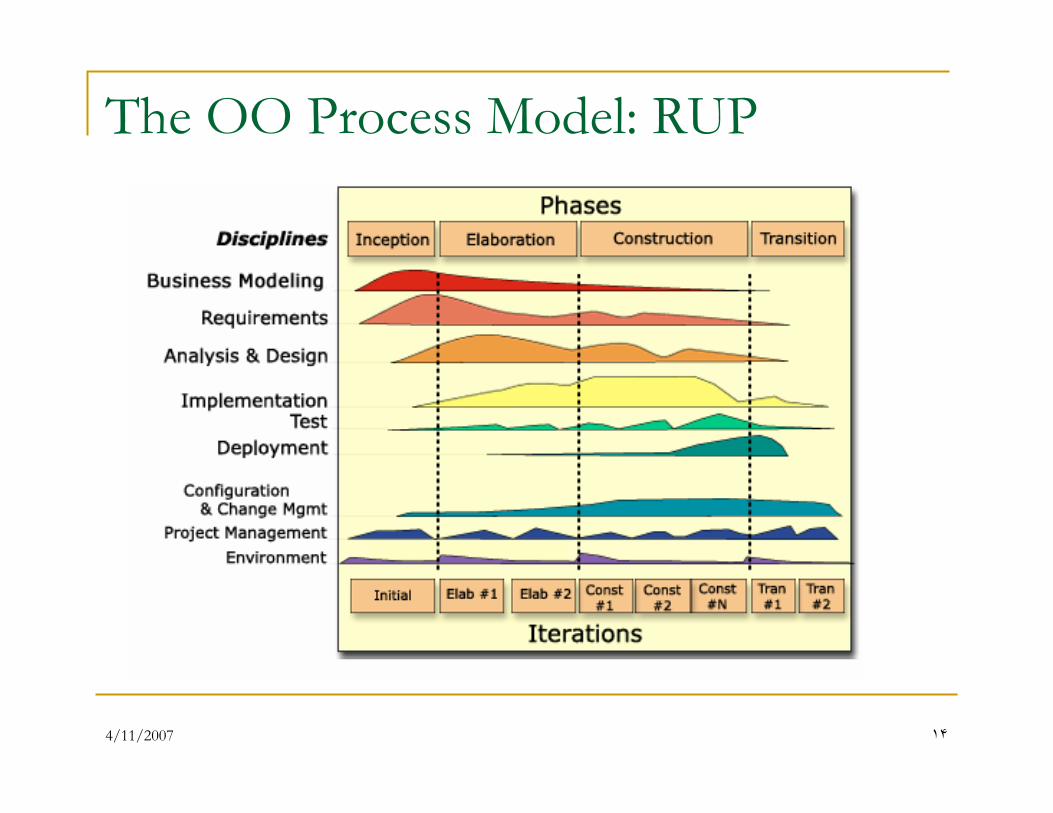
The OO Process Model: RUP
4/11/2007 ١�
The purposes of business modeling
� To understand the structure and the dynamics of the organization in which a system is to be deployed (the target organization).
� To understand current problems in the target organization and identify improvement potentials.
� To ensure that customers, end users, and developers have a common understanding of the
target organization.
� To derive the system requirements needed to
support the target organization.
4/11/2007 ١�
Artifacts of Business Modeling
� Business Use Case Model
� Business Object Model
� Business Glossary
� Business Rules
� Business Vision
� Target Organization Assessment
� …
4/11/2007 ١٧
Scope of Business Modeling
� Organization Chart
� Domain Modeling
� One Business Many Systems
� Generic Business Model
� New Business
� Revamp Business
4/11/2007 ١٨
Organization Chart
� Build a simple map of the organization and its
processes to get a better understanding of
requirements.
� Business modeling is part of software
engineering project (Inception phase)
� No change in organization (no BPI/BPR)
4/11/2007 ١٩
Domain Modeling
� Build a model of information at a business
level (without considering workflows)
� As part of software engineering project
� Inception and Elaboration
4/11/2007 ٢٠
One business- Many systems
� Building a large system or a family of
applications
� One business model will serve as input to
several SE projects.
� Help to Find functional requirements and
architecture of the application family
4/11/2007 ٢١
Generic Business Model
� One application- several organizations
� Avoid complex requirements
� BPI
4/11/2007 ٢٢
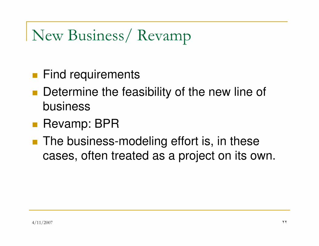
New Business/ Revamp
� Find requirements
� Determine the feasibility of the new line of
business
� Revamp: BPR
� The business-modeling effort is, in these
cases, often treated as a project on its own.
4/11/2007 ٢٣
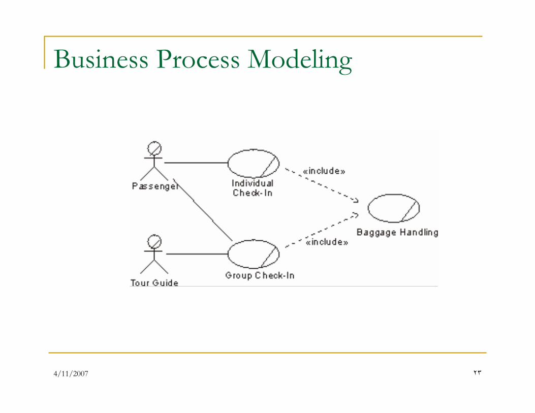
Business Process Modeling
4/11/2007 ٢�
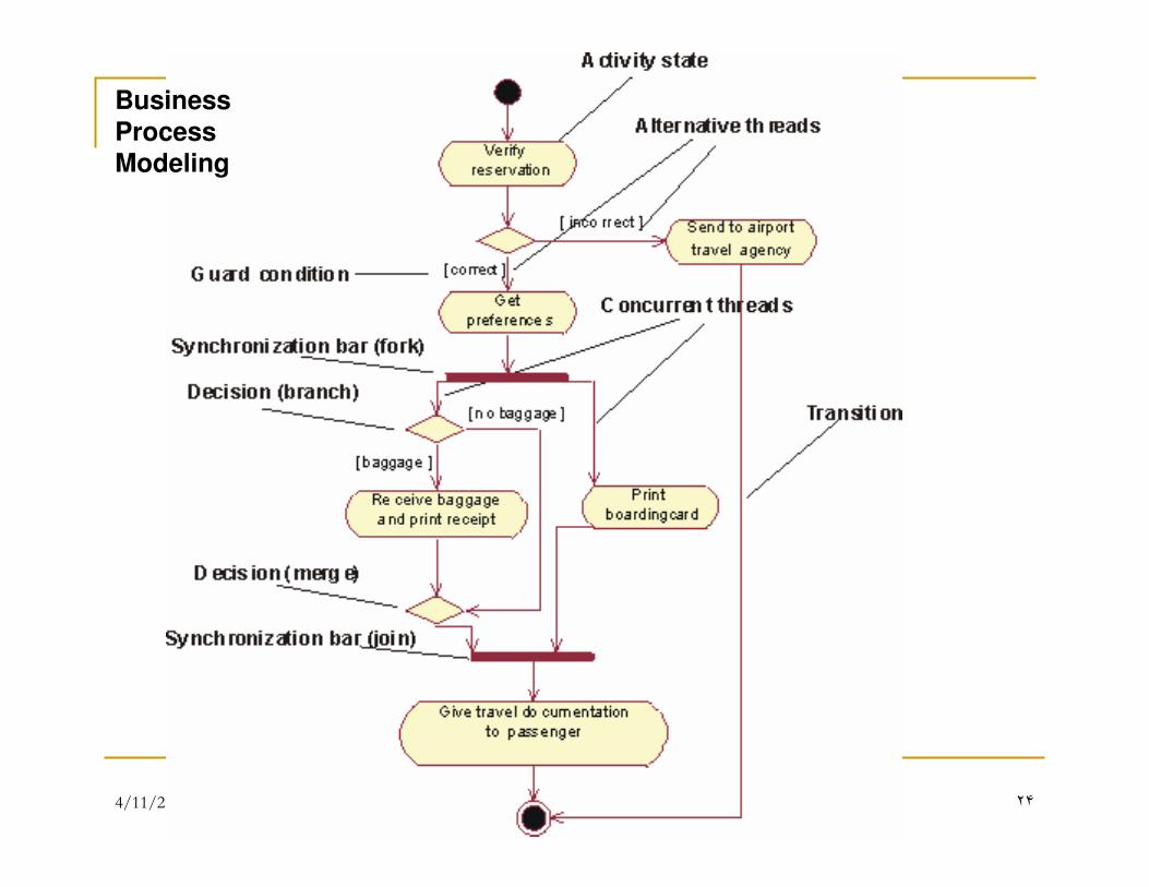
Business
Process Modeling
4/11/2007 ٢�
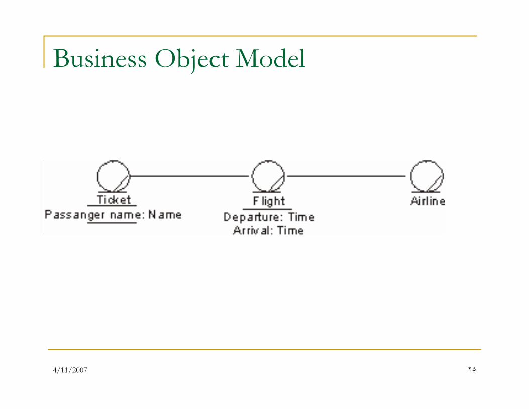
Business Object Model
4/11/2007 ٢�
Requirement Management
� To establish and maintain agreement with the customers and other stakeholders on what the system should do.
� To provide system developers with a better understanding of the system requirements.
� To define the boundaries of the system.
� To provide a basis for planning iterations.
� To provide a basis for estimating cost and time to develop the system.
� To define a user-interface for the system, focusing on the needs and goals of the users.
4/11/2007 ٢٧
Requirements: Artifacts
� Use Case Model
� SRS
� Vision
� Supplementary Specification
� Glossary
� …
4/11/2007 ٢٨
Analysis: Purpose
� To transform the requirements into a design
of the system.
� To evolve a robust architecture for the
system.
4/11/2007 ٢٩
Analysis: Artifacts
� Analysis Model
� Software Architecture Document
A First Look
4/11/2007 ٣١
Analysis: Finding Classes
� CRC Card
� Responsibility Driven Method
� Use Case Driven Method
4/11/2007 ٣٢
Analysis Phase: What’s Next?
� Find the objects needed for the use cases
� Determine the responsibility for each object
� Determine what objects work together to
complete a use case
� Verify all use cases are covered
4/11/2007 ٣٣
Identifying Objects
� Work use case by use case
� Extract noun phrases and build a list
� Identify candidate objects� Physical objects
� Conceptual entities
� Categories of objects
� External interfaces
4/11/2007 ٣�
CRC Cards (1)
Class, Responsibility, Collaborator
� Helps to find object interactions
� Gives a physical entity (the card) to work with
� 4” x 6” note cards recommended
� 3 pieces of data:
� Class – name and purpose of the class
� Responsibility – what the class knows and the behaviors it performs
� Collaborator – Other classes that need to help with a responsibility
4/11/2007 ٣�
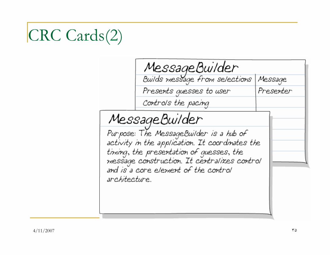
CRC Cards(2)
4/11/2007 ٣�
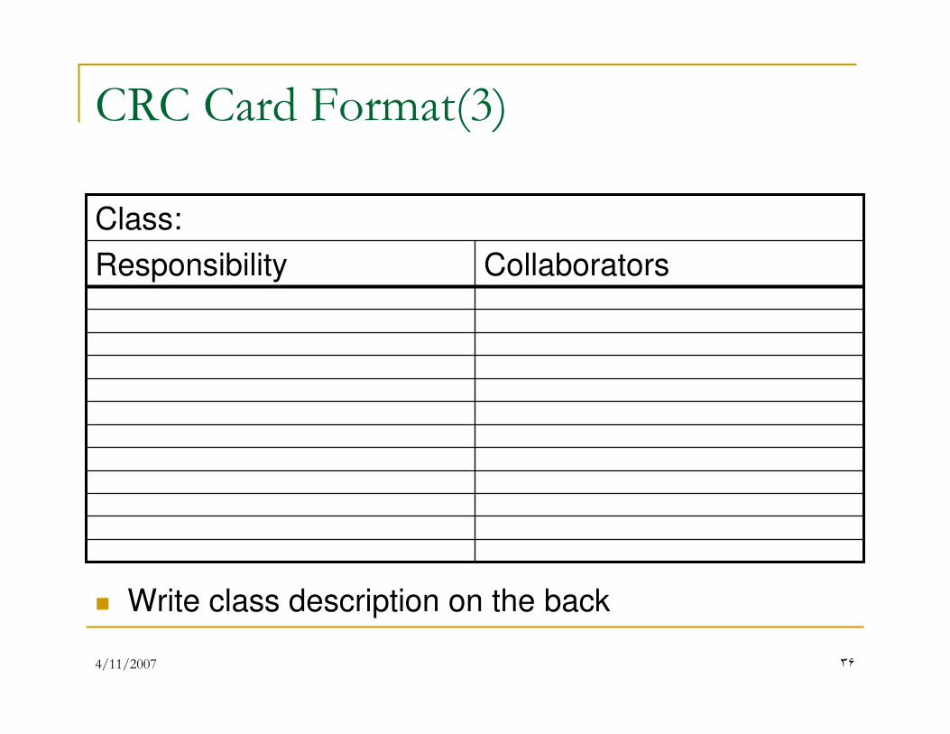
CRC Card Format(3)
CollaboratorsResponsibility
Class:
� Write class description on the back
4/11/2007 ٣٧
CRC Cards (4)
� Make 1 CRC card for each object in your list
� Fill in the class name
� Naming is important – try to name classes so their role
in the problem domain is obvious
� Use standard terminology where possible (i.e. from domain glossary or dictionary)
� Write description on the back of the card
� Helps clarify why the card exists
� Documents your thinking at this point in time
� Leave other sections blank for now
4/11/2007 ٣٨
Analysis Phase: What’s Next?
� Find the objects needed for the use cases
� Determine the responsibility for each object
� Determine what objects work together to
complete a use case
� Verify all use cases are covered
4/11/2007 ٣٩
Responsibilities
� The knowledge an object maintains
� Actions an object can perform
� Only the publicly available services at this
stage
� Still only what gets done, not how
4/11/2007 �٠
Identifying Responsibilities
� Work use case by use case
� Identify verbs that represent an action an
object must perform
� What does the class have to be able to do?
� Identify information that some object must
maintain
� What does the class need to know?
4/11/2007 �١
CRC Cards (5)
� Add responsibilities to CRC card as a phrase
� E.g. “Know machine name of master controller”
� If card fills up:
� May have gone into too much detail
� May be good indication to split class into several
classes
� Leads to more flexible design
4/11/2007 �٢
Analysis Phase: What’s Next?
� Find the objects needed for the use cases
� Determine the responsibility for each object
� Determine what objects work together to
complete a use case
� Verify all use cases are covered
4/11/2007 �٣
Identifying Collaborators
� For each responsibility ask:
� Is the class capable of handling this responsibility itself?
� If not, what does it need (that it can’t do by itself)?
� From what other class can it acquire what it
needs?
4/11/2007 ��
Identifying Collaborations to Offer
� For each class ask:
� What does this class do or know?
� What other classes need the information I have?
� If a class has no interactions, discard it
� Write the name of the class providing the
collaboration to the right of the responsibility
it helps fulfill
4/11/2007 ��
Analysis Phase: What’s Next?
� Find the objects needed for the use cases
� Determine the responsibility for each object
� Determine what objects work together to
complete a use case
� Verify all use cases are covered
4/11/2007 ��
Use Case Verification
� Walk through all flows of all use cases
� When an unmet responsibility is discovered
� Add it to an existing class; or
� Create a new class
� When a missing class is discovered, make a
CRC card for it
� Keep repeating until you can walk through
each flow without discovering a new class,
responsibility or collaborator
4/11/2007 �٧
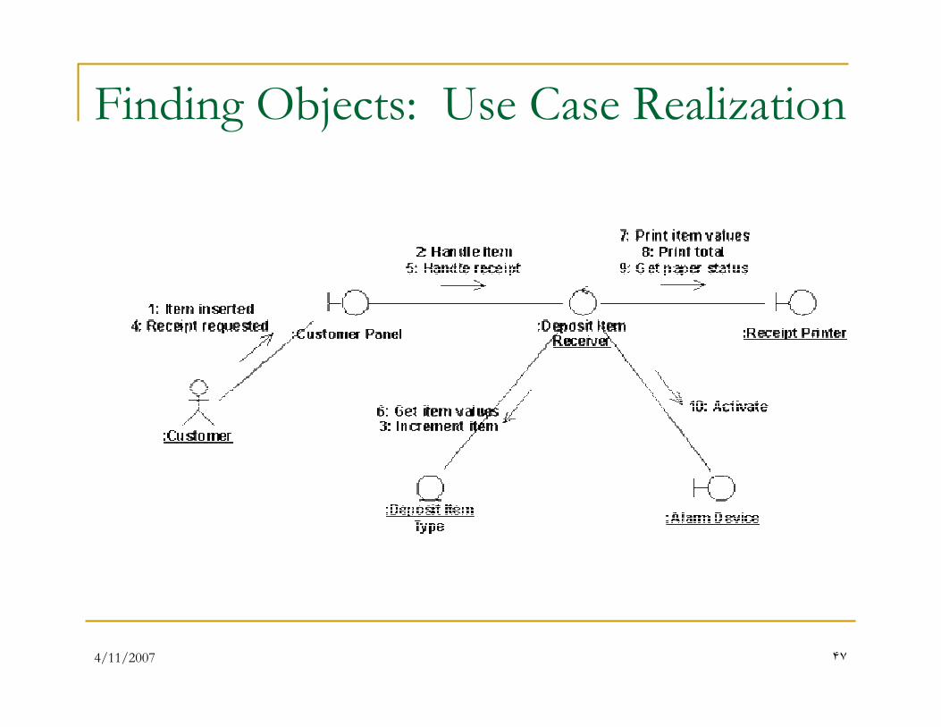
Finding Objects: Use Case Realization
4/11/2007 �٨
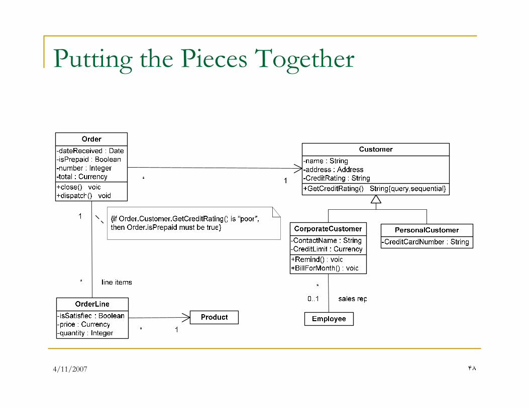
Putting the Pieces Together
4/11/2007 �٩
4/11/2007 �٠
Analysis and Design: Artifacts
� Analysis Model
� Software Architecture
4/11/2007 �١
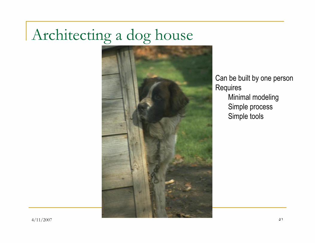
Architecting a dog house
Can be built by one person
Requires
Minimal modeling
Simple process
Simple tools
4/11/2007 �٢
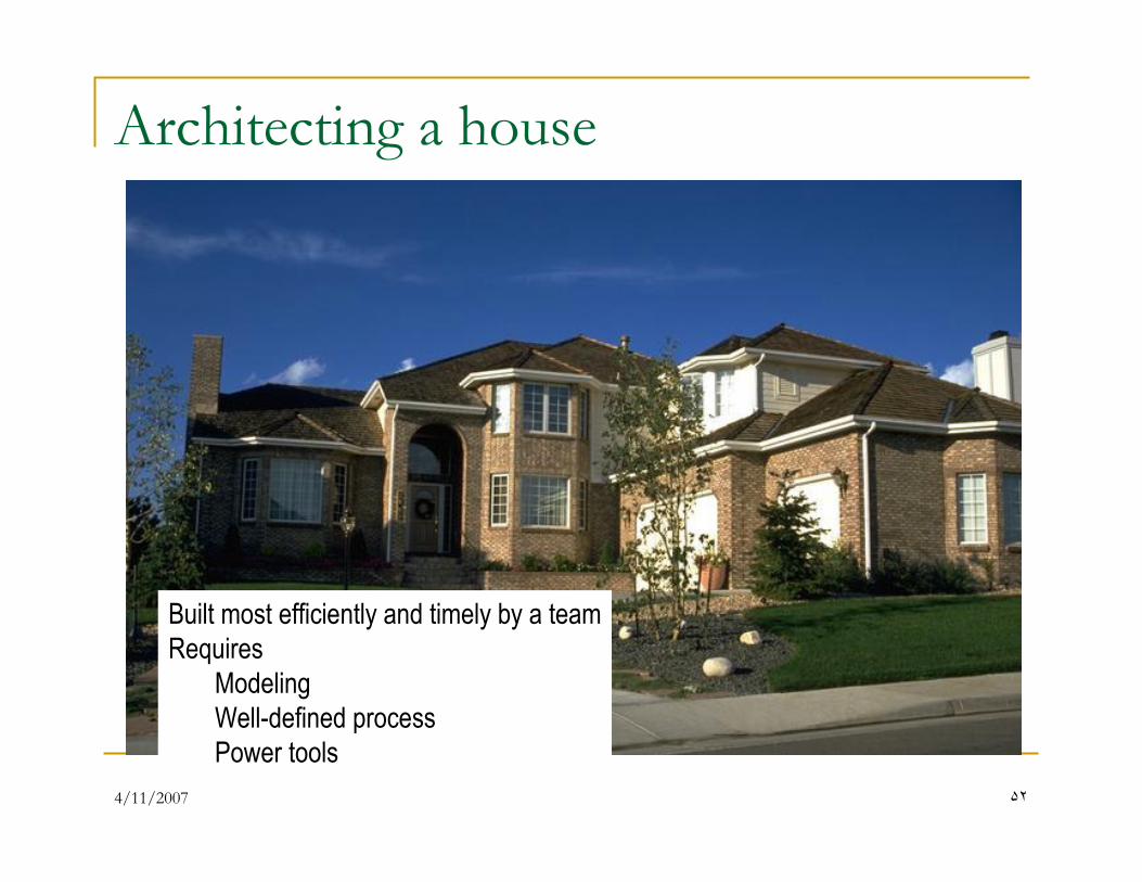
Architecting a house
Built most efficiently and timely by a team
Requires
Modeling
Well-defined process
Power tools

4/11/2007 �٣
Architecting a high rise
4/11/2007 ��
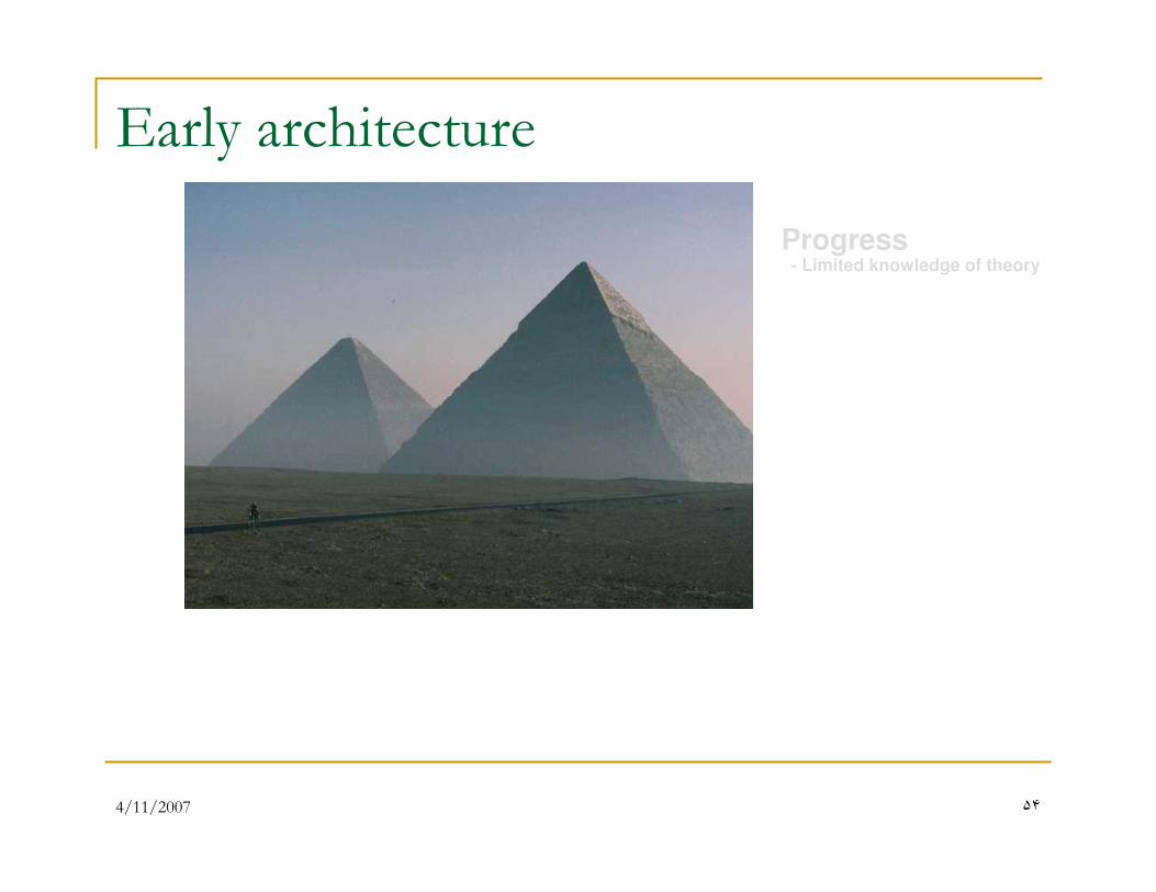
Early architecture
Progress- Limited knowledge of theory
4/11/2007 ��
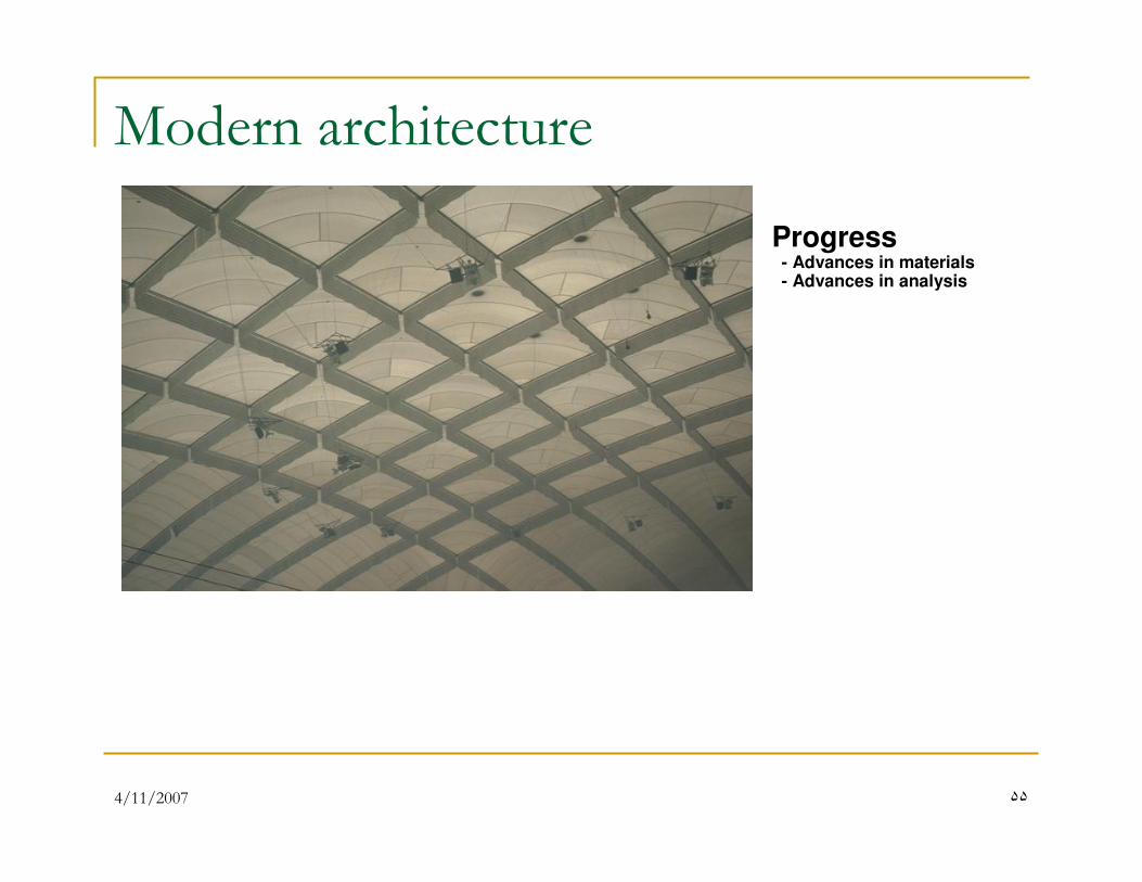
Modern architecture
Progress- Advances in materials- Advances in analysis
4/11/2007 ��
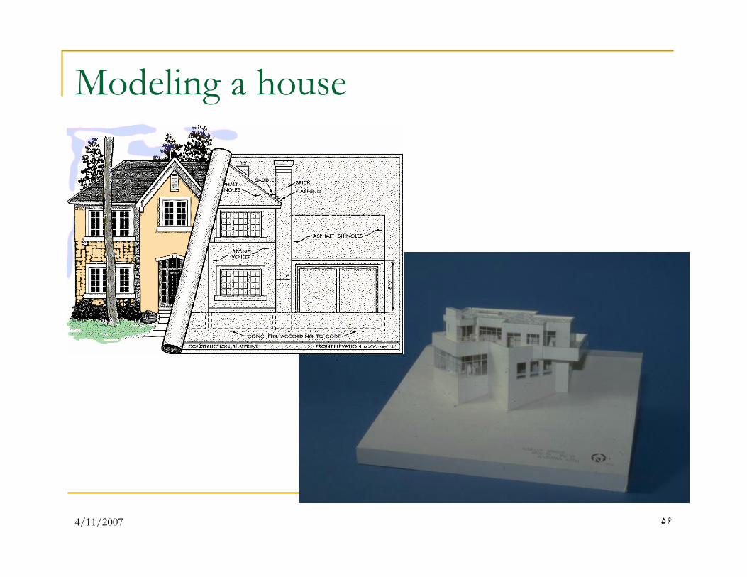
Modeling a house
4/11/2007 �٧
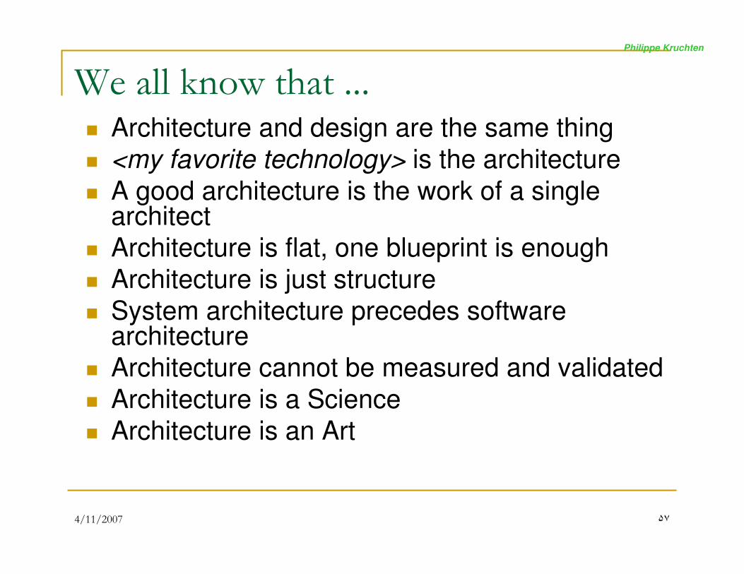
We all know that ...� Architecture and design are the same thing
� <my favorite technology> is the architecture
� A good architecture is the work of a single architect
� Architecture is flat, one blueprint is enough
� Architecture is just structure
� System architecture precedes software architecture
� Architecture cannot be measured and validated
� Architecture is a Science
� Architecture is an Art
Philippe Kruchten
4/11/2007 �٨
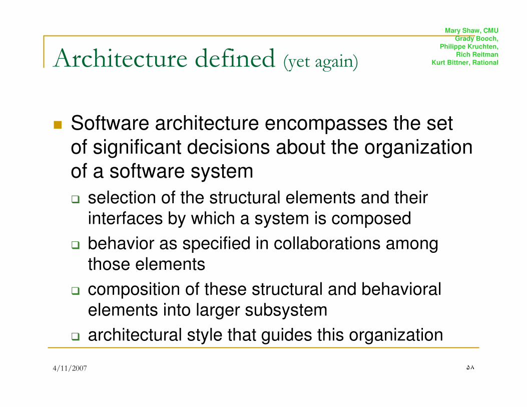
Architecture defined (yet again)
� Software architecture encompasses the set
of significant decisions about the organization
of a software system
� selection of the structural elements and their interfaces by which a system is composed
� behavior as specified in collaborations among those elements
� composition of these structural and behavioral elements into larger subsystem
� architectural style that guides this organization
Mary Shaw, CMU
Grady Booch,
Philippe Kruchten,
Rich Reitman
Kurt Bittner, Rational
4/11/2007 �٩
Architectural style
� An architecture style defines a family of
systems in terms of a pattern of structural
organization.
� An architectural style defines
� a vocabulary of components and connector types
� a set of constraints on how they can be combined
� one or more semantic models that specify how a
system’s overall properties can be determined from the properties of its parts
Mary Shaw, CMU
4/11/2007 �٠
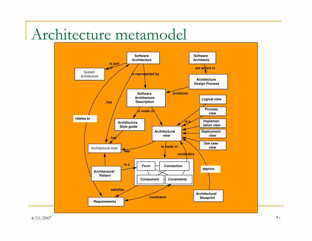
Architecture metamodelSoftware
Architecture
Software
Architecture
Description
Architectural
view
is made of
is represented by
Architecture
Design Process
produces
Form
Component
Connection
Architectural
Pattern
is a
is made of
Software
Architects
are actors in
Logical view
Process
view
Implemen-
tation view
Deployment
view
Requirements
satisfies
Architectural style
has
has
has
is a
System
architecture
is part
of
Architecture
Style guide
Constraints
constrains
constrains
Use case
view
relates to
Architectural
Blueprint
depicts
4/11/2007 �١
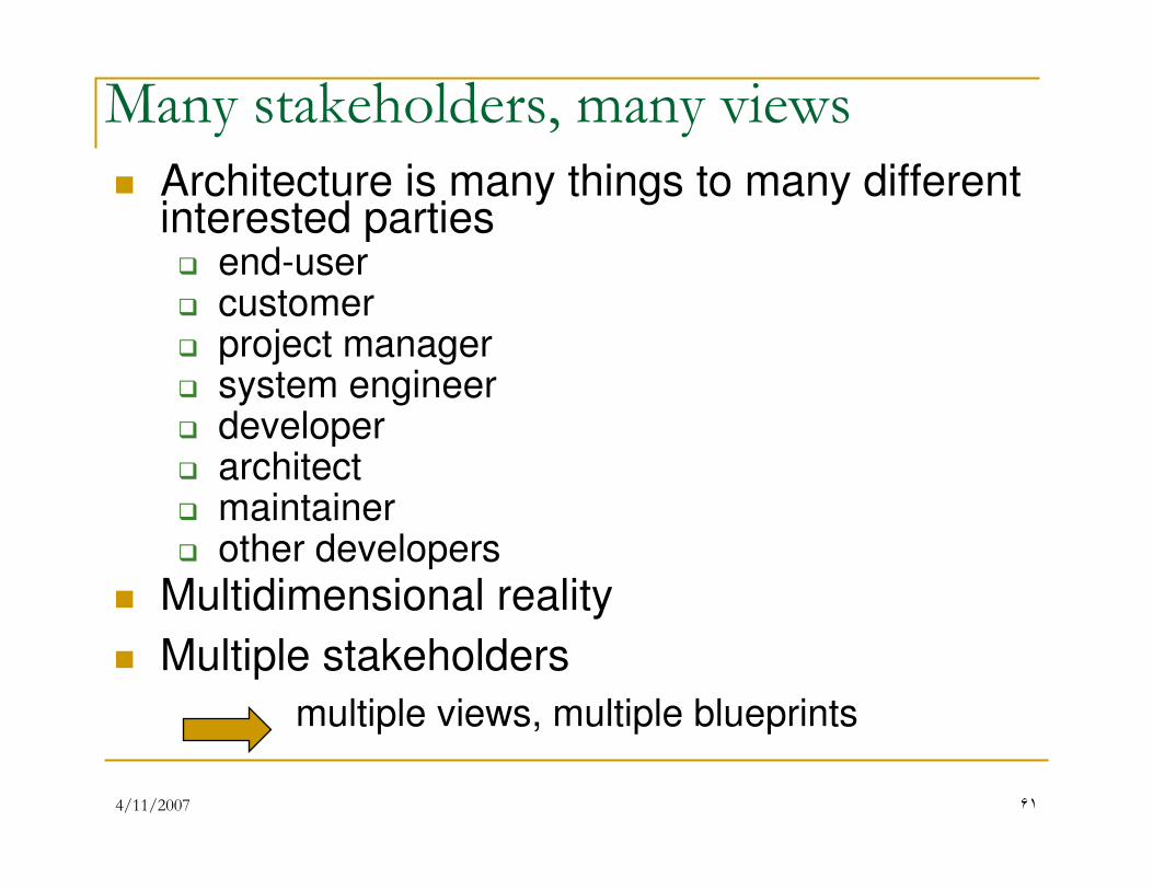
Many stakeholders, many views
� Architecture is many things to many different interested parties� end-user� customer� project manager� system engineer� developer� architect� maintainer� other developers
� Multidimensional reality
� Multiple stakeholders
multiple views, multiple blueprints
4/11/2007 �٢
Architectural view
� An architectural view is a simplified
description (an abstraction) of a system from
a particular perspective or vantage point,
covering particular concerns, and omitting
entities that are not relevant to this
perspective
4/11/2007 �٣
Architecturally significant elements
� Not all design is architecture
� Main “business” classes
� Important mechanisms
� Processors and processes
� Layers and subsystems
� Architectural views = slices through models
4/11/2007 ��
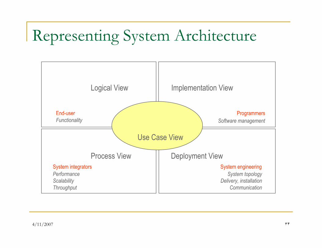
Representing System Architecture
Logical View
End-user
Functionality
Implementation View
Programmers
Software management
Process View
Performance
Scalability
Throughput
System integrators
Deployment View
System topology
Delivery, installation
Communication
System engineering
Conceptual Physical
Use Case View
4/11/2007 ��
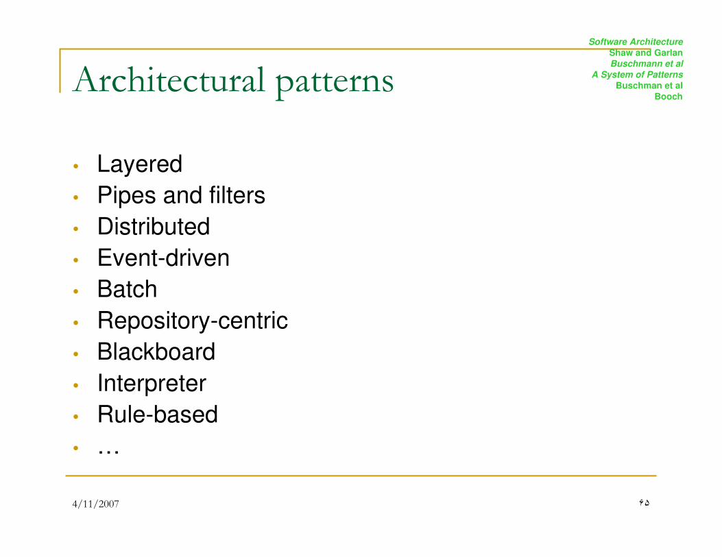
Architectural patterns
� Layered
� Pipes and filters
� Distributed
� Event-driven
� Batch
� Repository-centric
� Blackboard
� Interpreter
� Rule-based
� …
Software Architecture
Shaw and Garlan
Buschmann et al
A System of Patterns
Buschman et al
Booch
4/11/2007 ��
The Design Process
� Design is a messy, iterative process
� Early descriptions tend to be less precise
� Later descriptions add
more precision and formality
4/11/2007 �٧
Object Oriented Design
� OOD transforms the analysis model created using OOA into a design model that serves as a blueprint for software construction.
� OOD results in a design that achieves a number of different levels of modularity.
� Subsystems: Major system components.
� Objects: Data and the operations.
…then get more precise
4/11/2007 �٩
Object-Oriented Design
responsibilitiesdesign
messagedesign
class and objectdesign
subsystemdesign
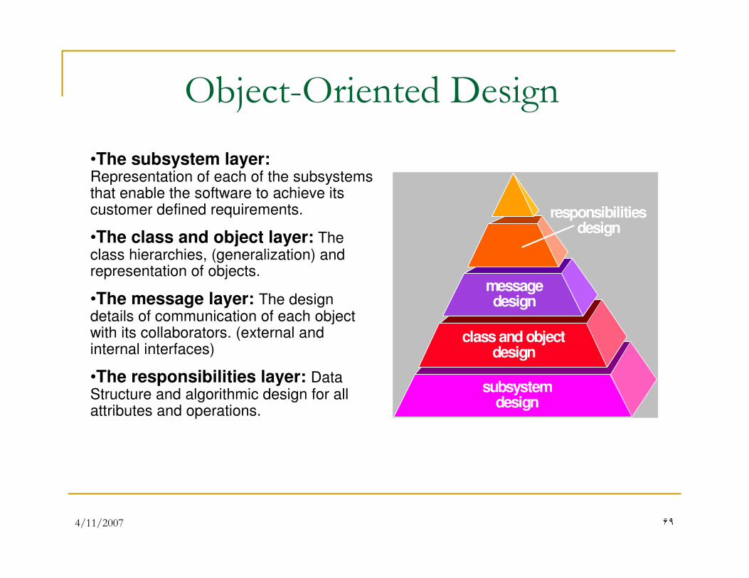
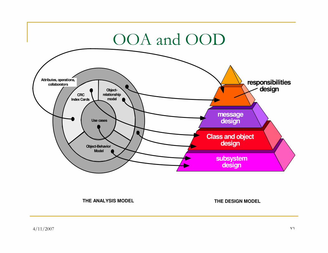
•The subsystem layer: Representation of each of the subsystems that enable the software to achieve its customer defined requirements.
•The class and object layer: The class hierarchies, (generalization) and representation of objects.
•The message layer: The design details of communication of each object with its collaborators. (external and internal interfaces)
•The responsibilities layer: Data Structure and algorithmic design for all attributes and operations.
4/11/2007 ٧٠
Object-Oriented Design� The design pyramid focuses exclusively on the design of
a specific product or system.
� Another layer of design which forms the foundation on
which the pyramid rests, exists.
� The foundation layer focuses on the design of domain
objects.
� Domain objects play a key role in building the
infrastructure for the OO system by providing support for:
� Human/computer interface activities,
� Task management,
� Data management.
4/11/2007 ٧١
OOA and OOD
Object-
relationshipmodel
Object-Behavior
Model
CRC
Index Cards
Attributes, operations,
collaborators
THE ANALYSIS MODEL
responsibilitiesdesign
messagedesign
Class and objectdesign
subsystemdesign
THE DESIGN MODEL
Use cases
4/11/2007 ٧٢
Generic Components for OOD
� Problem domain component—the subsystems that are
responsible for implementing customer requirements
directly;
� Human interaction component —the subsystems that
implement the user interface (this included reusable
GUI subsystems);
� Task Management Component—the subsystems that
are responsible for controlling and coordinating
concurrent tasks that may be packaged within a
subsystem or among different subsystems;
� Data management component—the subsystem that is
responsible for the storage and retrieval of objects.
4/11/2007 ٧٣
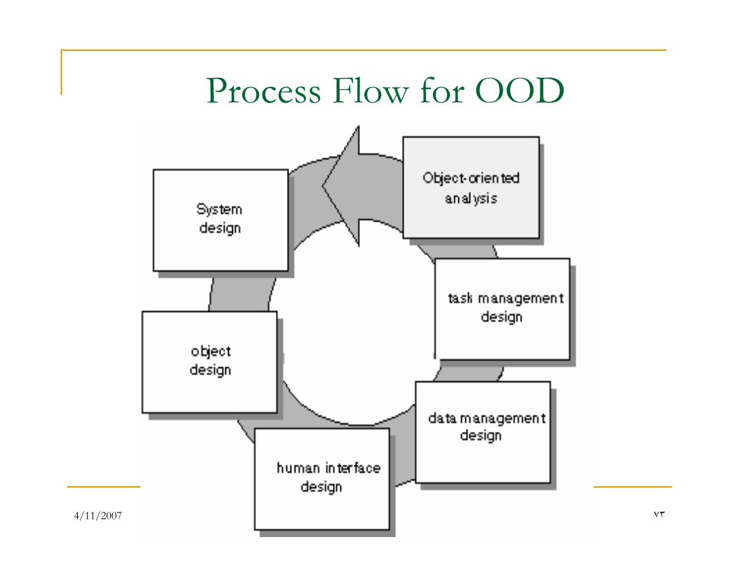
Process Flow for OOD
4/11/2007 ٧�
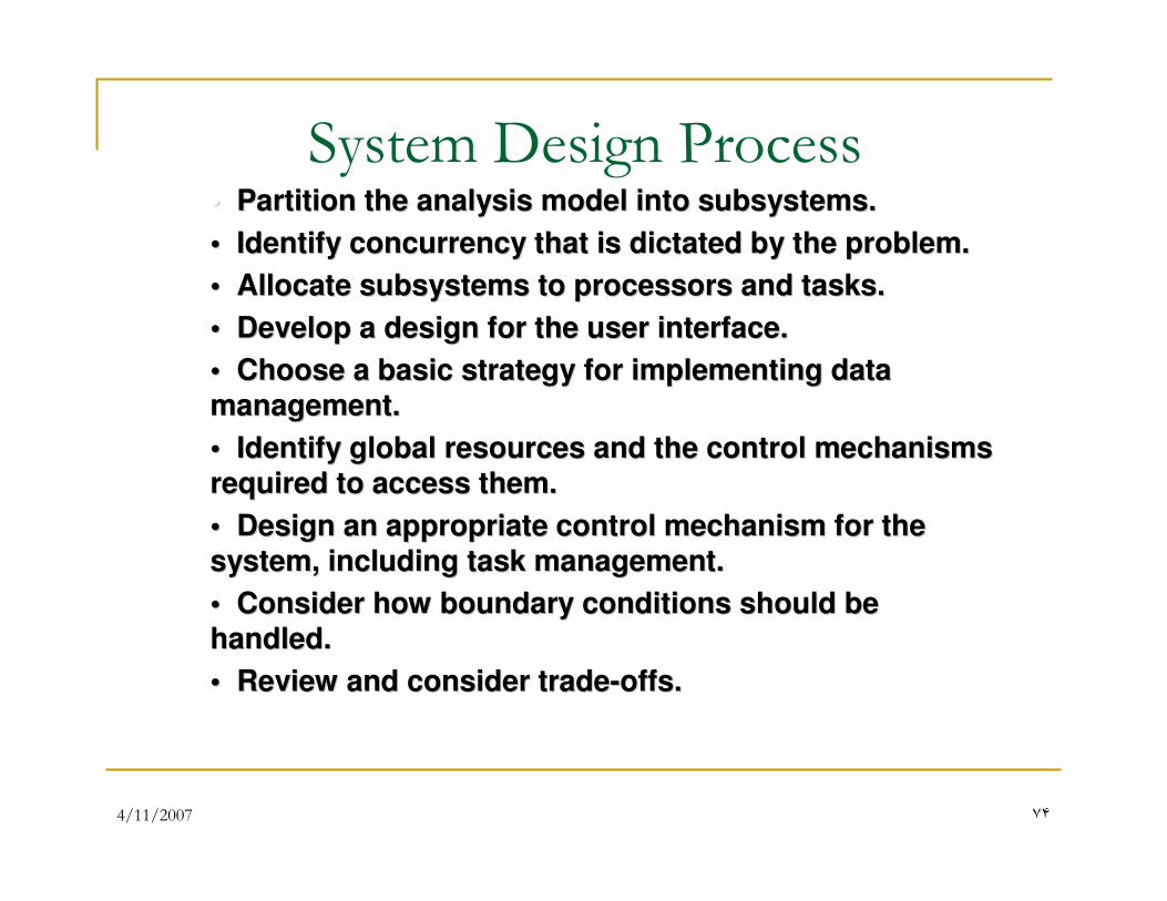
System Design Process•• Partition the analysis model into subsystems.Partition the analysis model into subsystems.
•• Identify concurrency that is dictated by the problem.Identify concurrency that is dictated by the problem.
•• Allocate subsystems to processors and tasks.Allocate subsystems to processors and tasks.
•• Develop a design for the user interface.Develop a design for the user interface.
•• Choose a basic strategy for implementing data Choose a basic strategy for implementing data
management.management.
•• Identify global resources and the control mechanisms Identify global resources and the control mechanisms
required to access them.required to access them.
•• Design an appropriate control mechanism for the Design an appropriate control mechanism for the
system, including task management.system, including task management.
•• Consider how boundary conditions should be Consider how boundary conditions should be
handled.handled.
•• Review and consider tradeReview and consider trade--offs.offs.
4/11/2007 ٧�
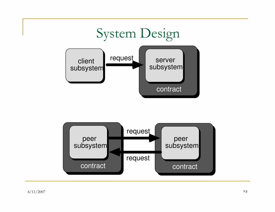
System Design
requestclientsubsystem
contract
contract contract
request
request
serversubsystem
peersubsystem
peersubsystem
4/11/2007 ٧�
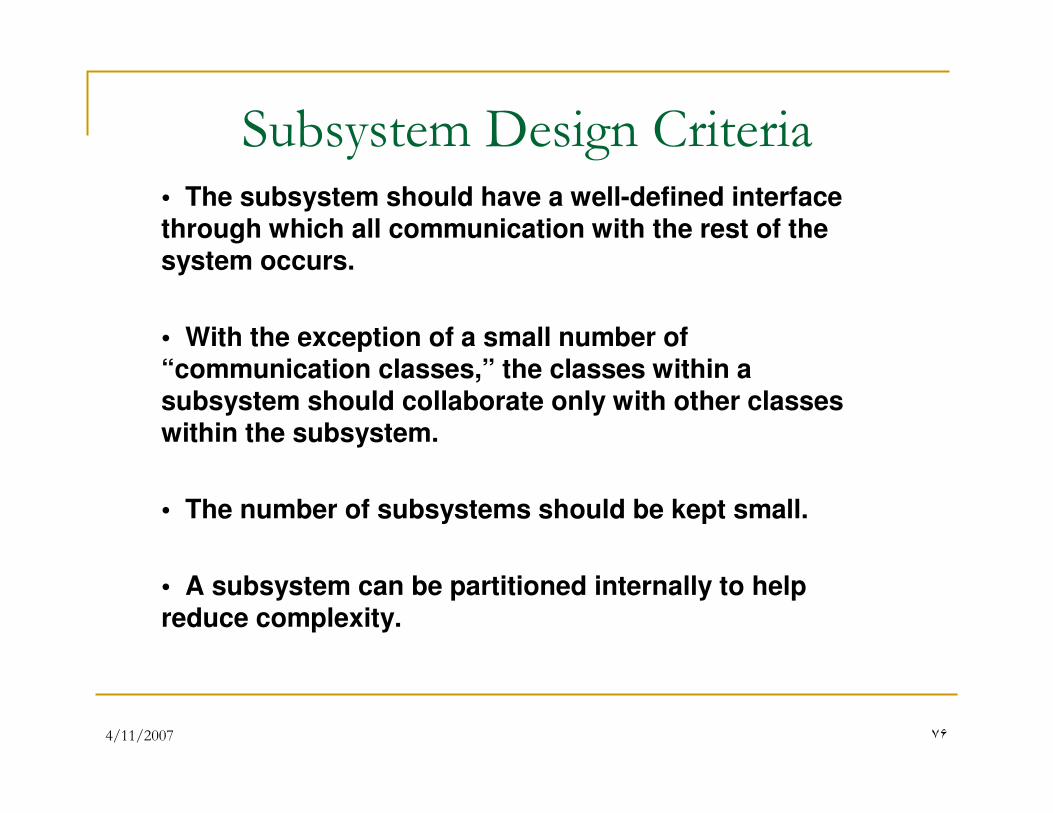
Subsystem Design Criteria• The subsystem should have a well-defined interface through which all communication with the rest of the system occurs.
• With the exception of a small number of “communication classes,” the classes within a subsystem should collaborate only with other classes within the subsystem.
• The number of subsystems should be kept small.
• A subsystem can be partitioned internally to help reduce complexity.
4/11/2007 ٧٧
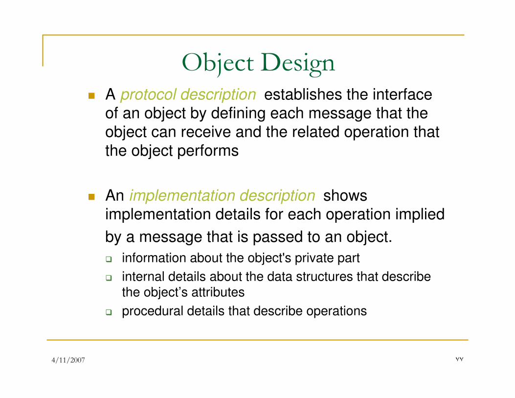
Object Design� A protocol description establishes the interface
of an object by defining each message that the
object can receive and the related operation that
the object performs
� An implementation description shows implementation details for each operation implied
by a message that is passed to an object.
� information about the object's private part
� internal details about the data structures that describe the object’s attributes
� procedural details that describe operations
4/11/2007 ٧٨
4/11/2007 ٧٩
4/11/2007 ٨٠
Case Study
� Weather Station
4/11/2007 ٨١
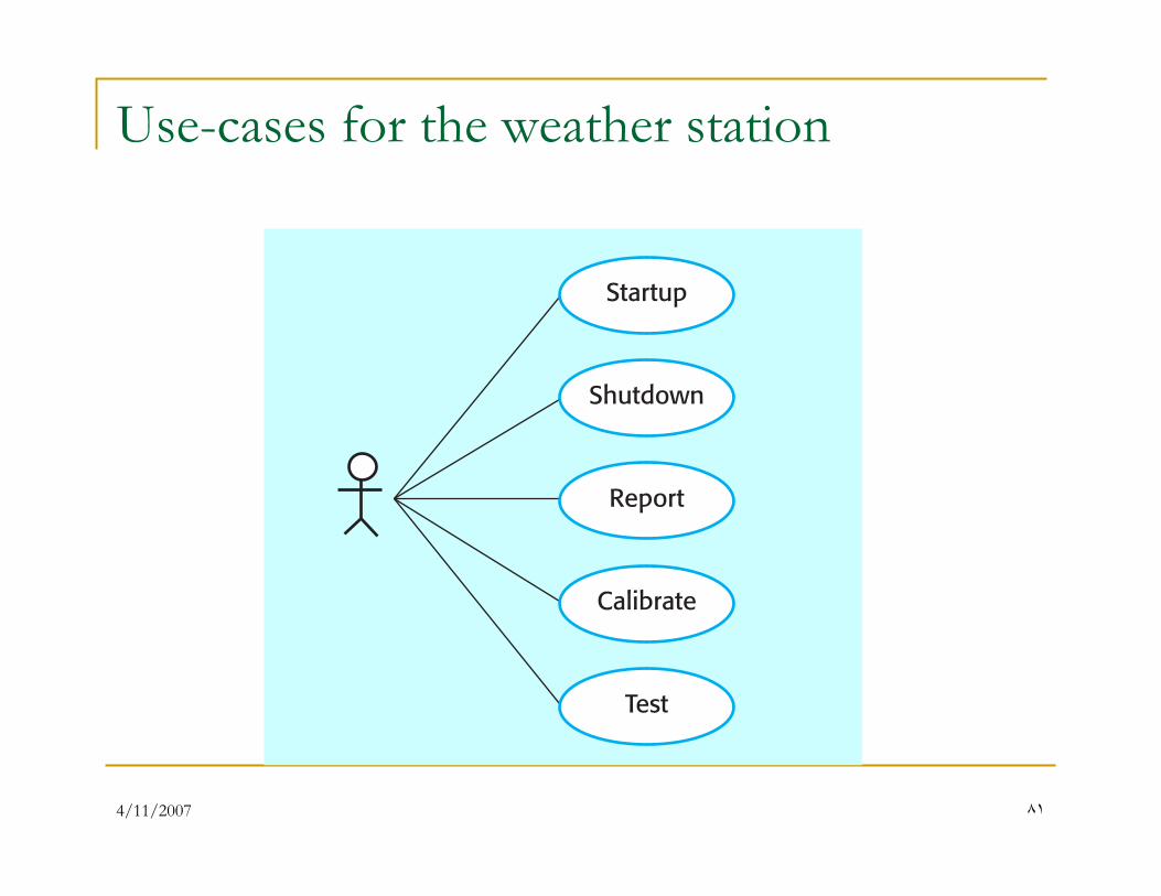
Use-cases for the weather station
4/11/2007 ٨٢
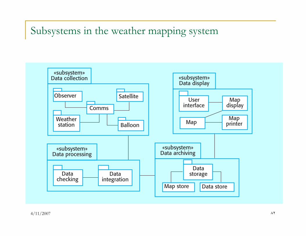
Subsystems in the weather mapping system
4/11/2007 ٨٣
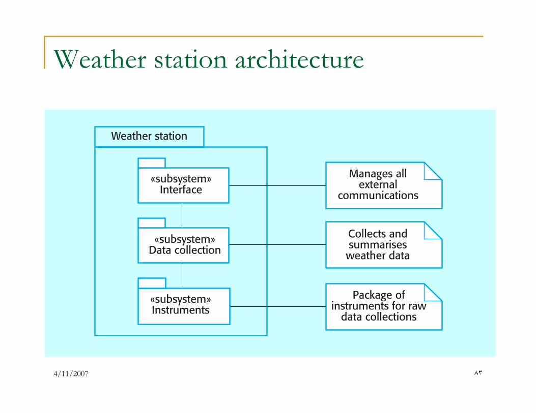
Weather station architecture
4/11/2007 ٨�
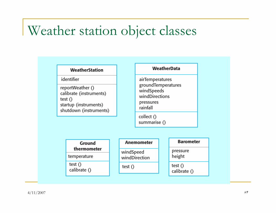
Weather station object classes
4/11/2007 ٨�
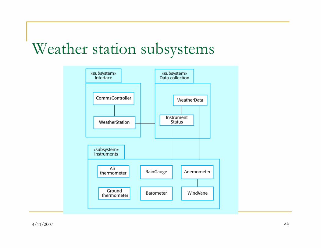
Weather station subsystems
4/11/2007 ٨�
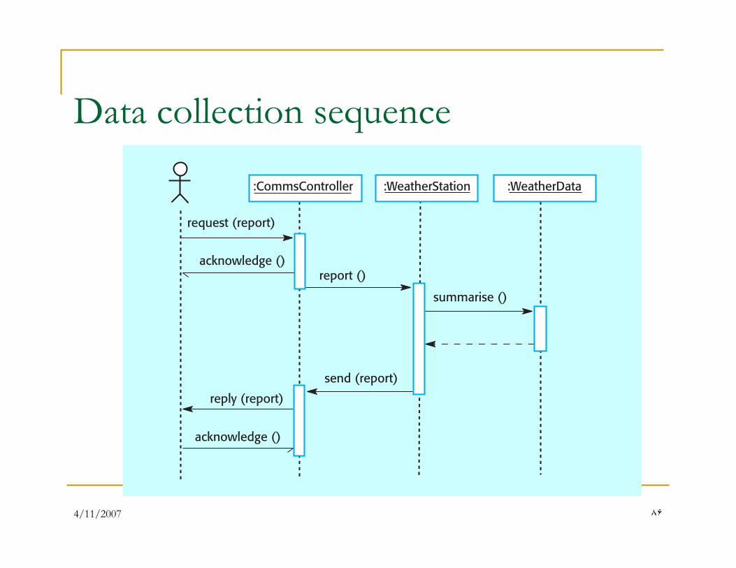
Data collection sequence
4/11/2007 ٨٧
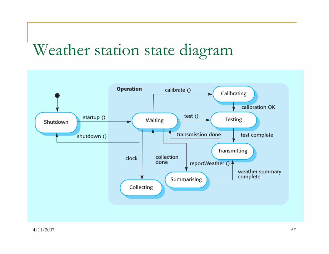
Weather station state diagram
4/11/2007 ٨٨
Design Patterns
... you’ll find recurring patterns of classes and communicating objects in many object-oriented systems. These patterns solve specific design problems and make object-oriented design more flexible, elegant, and ultimately reusable. They help designers reuse successful designs by basing new designs on prior experience. A designer who is familiar with such patterns can apply them immediately to design problems without having to rediscover them.
Gamma and his colleagues [GAM95]
4/11/2007 ٨٩
Design Pattern Attributes
� The design pattern name is an abstraction that conveys
significant meaning about it applicability and intent.
� The problem description indicates the environment and
conditions that must exist to make the design pattern
applicable.
� The pattern characteristics indicate the attributes of the
design that may be adjusted to enable the pattern to
accommodate into a variety of problems.
� The consequences associated with the use of a design
pattern provide an indication of the ramifications of
design decisions.
4/11/2007 ٩٠
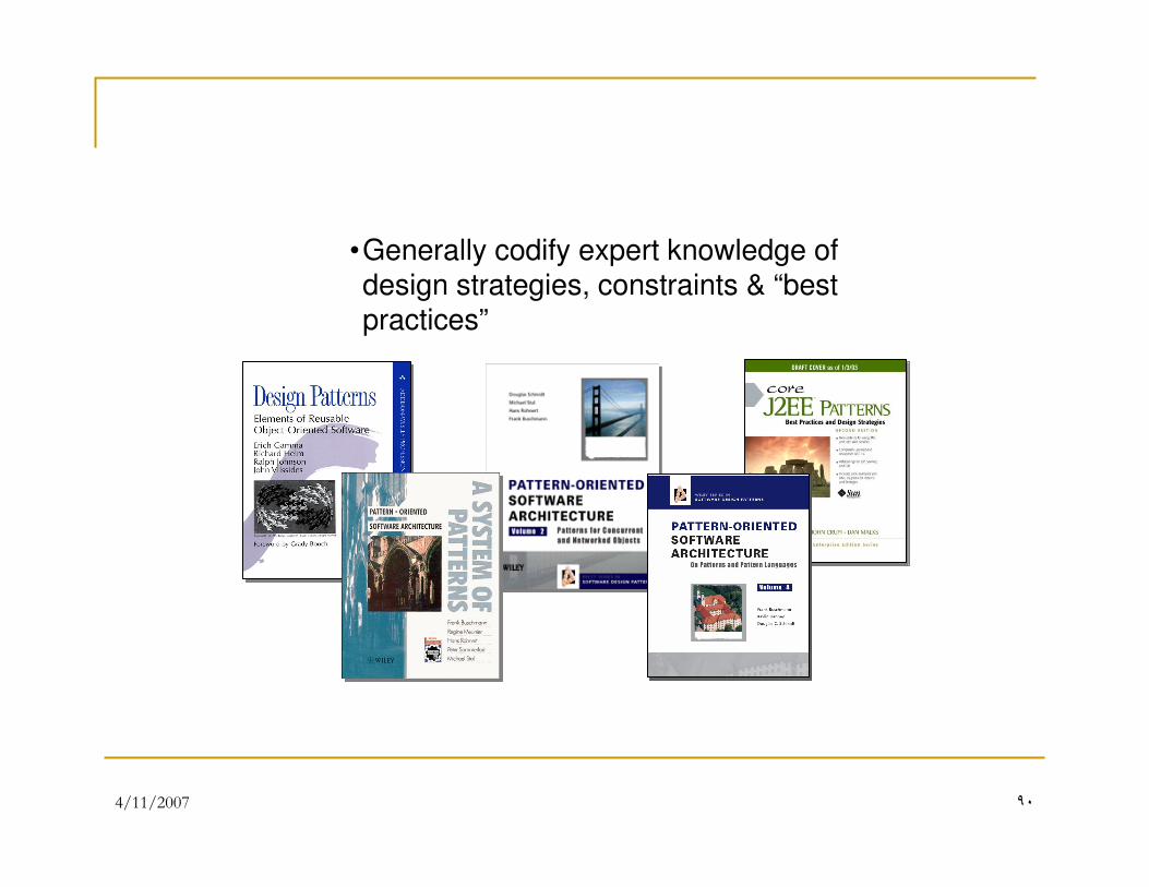
•Generally codify expert knowledge of design strategies, constraints & “best practices”
4/11/2007 ٩١
End.