Embed Size (px)
Citation preview
Chapter 5
Fundamentals of Frequency Modulation
Topics Covered
● 5-1: Basic Principles of Frequency Modulation
● 5-2: Principles of Phase Modulation● 5-3: Modulation Index and Sidebands● 5-4: Noise-Suppression Effects of FM● 5-5: Frequency Modulation Versus Amplitude
Modulation
5-1: Basic Principles of Frequency Modulation
● A sine wave carrier can be modified for the purpose of transmitting information from one place to another by varying its frequency. This is known as frequency modulation (FM).
● In FM, the carrier amplitude remains constant and the carrier frequency is changed by the modulating signal.
5-1: Basic Principles of Frequency Modulation
● As the amplitude of the information signal varies, the carrier frequency shifts proportionately.
● As the modulating signal amplitude increases, the carrier frequency increases.
● With no modulation the carrier is at its normal center or resting frequency.
5-1: Basic Principles of Frequency Modulation
● Frequency deviation (fd) is the amount of change in carrier frequency produced by the modulating signal.
● The frequency deviation rate is how many times per second the carrier frequency deviates above or below its center frequency.
● e.g: if the modulating signal is a 500 Hz sine wave, the carrier shifts above and below the center frequency 500 times per second.
● The frequency of the modulating signal determines the frequency deviation rate.
5-1: Basic Principles of Frequency Modulation
● Example ● A transmitter operates on a frequency of 915 MHz.
The maximum FM deviation is ± 12.5 kHz. What are the maximum and minimum frequencies that occur during modulation.
● Solution ● 915 MHz = 915,000 kHz● Maximum deviation = 915,000 + 12.5 = 915,012.5
kHz● Minimum deviation = 915,000 - 12.5 = 914,987.5 kHz
5-1: Basic Principles of Frequency Modulation
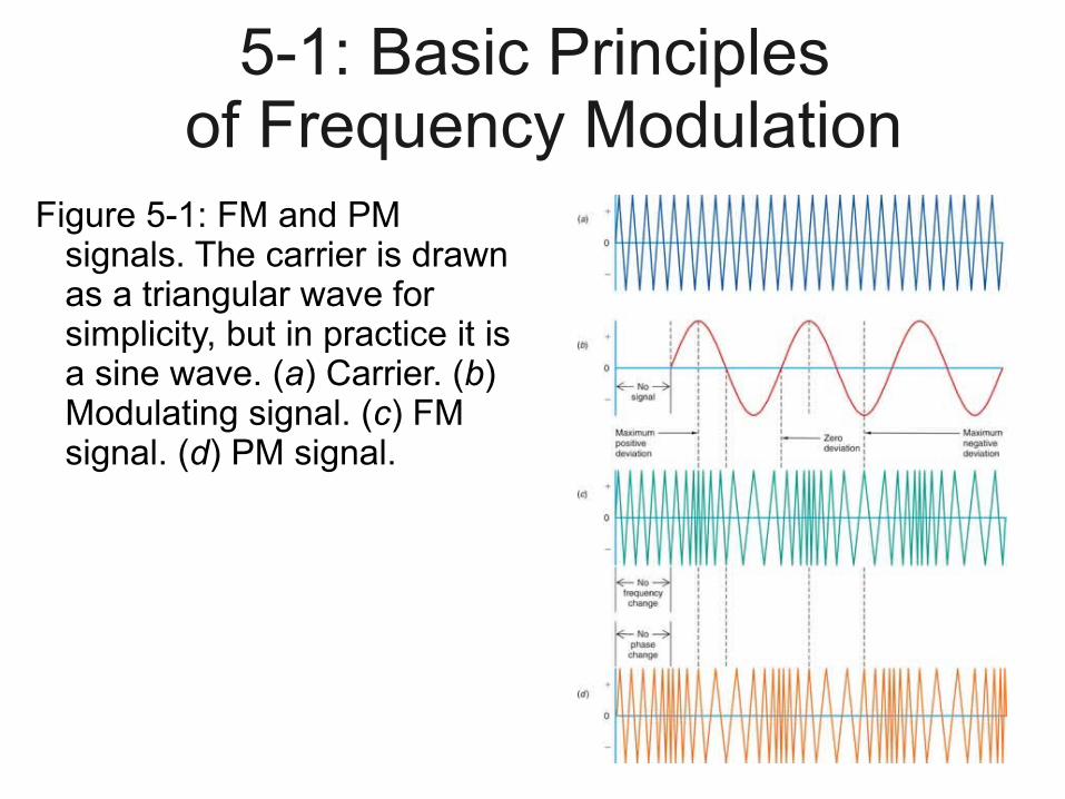
Figure 5-1: FM and PM signals. The carrier is drawn as a triangular wave for simplicity, but in practice it is a sine wave. (a) Carrier. (b) Modulating signal. (c) FM signal. (d) PM signal.
5-3: Modulation Index and Sidebands
● Any modulation process produces sidebands.
● When a constant-frequency sine wave modulates a carrier, two side frequencies are produced.
● Side frequencies are the sum and difference of the carrier and modulating frequency.
● The bandwidth of an FM signal is usually much wider than that of an AM signal with the same modulating signal.
5-3: Modulation Index and Sidebands
Modulation Index● The ratio of the frequency deviation to the
modulating frequency is known as the modulation index (mf).
● In most communication systems using FM, maximum limits are put on both the frequency deviation and the modulating frequency.
● In standard FM broadcasting, the maximum permitted frequency deviation is 75 kHz and the maximum permitted modulating frequency is 15 kHz.
● The modulation index for standard FM broadcasting is therefore 5.
5-3: Modulation Index and Sidebands
Bessel Functions ● The equation that expresses the phase angle in
terms of the sine wave modulating signal is solved with a complex mathematical process known as Bessel functions.
● Bessel coefficients are widely available and it is not necessary to memorize or calculate them.
5-3: Modulation Index and Sidebands
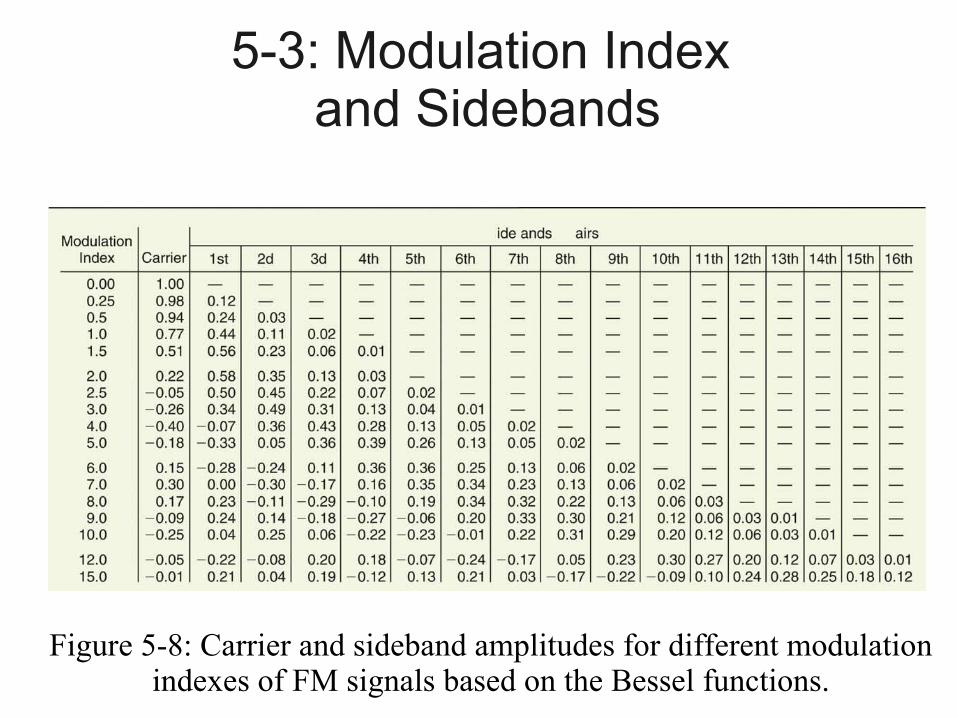
Figure 5-8: Carrier and sideband amplitudes for different modulation indexes of FM signals based on the Bessel functions.
5-3: Modulation Index and Sidebands
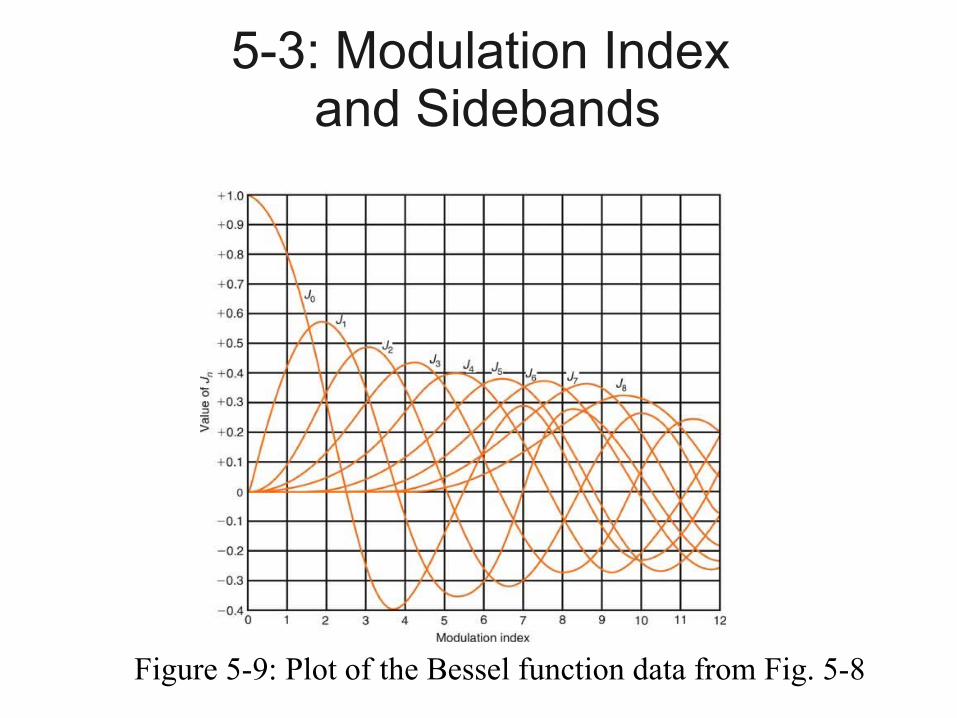
Figure 5-9: Plot of the Bessel function data from Fig. 5-8.
5-3: Modulation Index and Sidebands
Bessel Functions ● The symbol ! means factorial. This tells you to
multiply all integers from 1 through the number to which the symbol is attached. (e.g. 5! Means 1 × 2 × 3 × 4 × 5 = 120)
● Narrowband FM (NBFM) is any FM system in which the modulation index is less than π/2 = 1.57, or
mf < π /2.● NBFM is widely used in communication. It conserves
spectrum space at the expense of the signal-to-noise ratio.
5-3: Modulation Index and Sidebands
FM Signal Bandwidth● The higher the modulation index in FM, the
greater the number of significant sidebands and the wider the bandwidth of the signal.
● When spectrum conservation is necessary, the bandwidth of an FM signal can be restricted by putting an upper limit on the modulation index.
5-3: Modulation Index and Sidebands
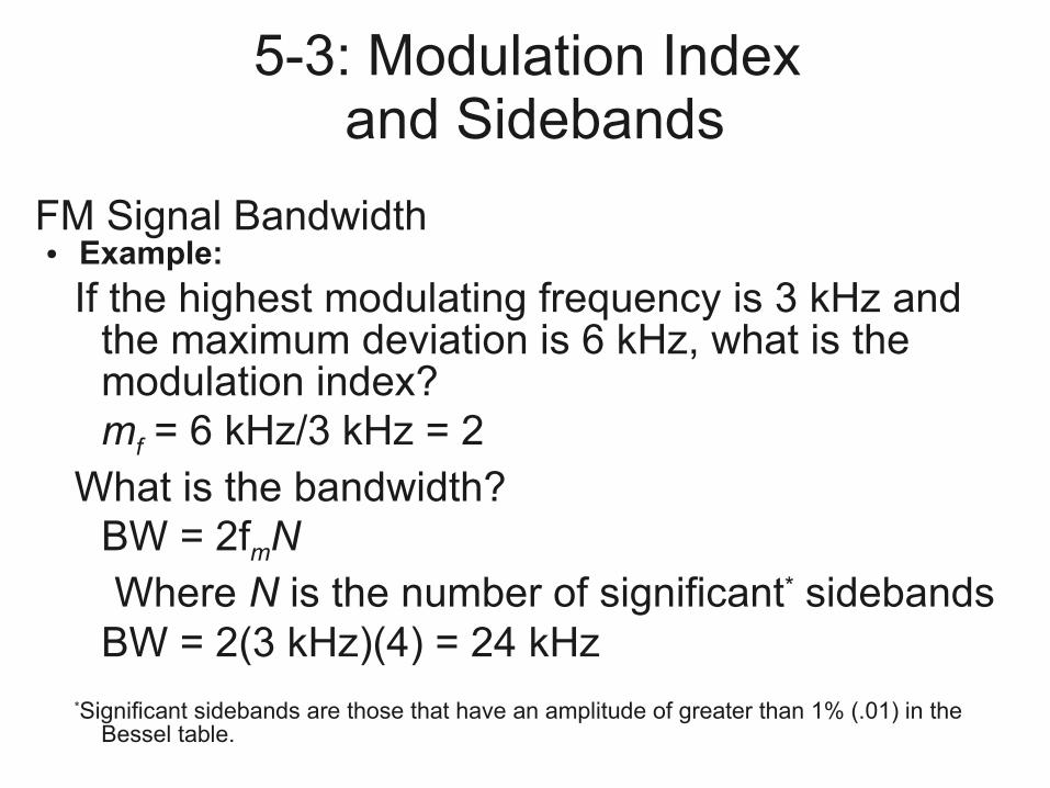
FM Signal Bandwidth● Example:
If the highest modulating frequency is 3 kHz and the maximum deviation is 6 kHz, what is the modulation index?mf = 6 kHz/3 kHz = 2
What is the bandwidth?BW = 2fmNWhere N is the number of significant* sidebands
BW = 2(3 kHz)(4) = 24 kHz*Significant sidebands are those that have an amplitude of greater than 1% (.01) in the
Bessel table.
5-4: Noise-Suppression Effects of FM
● Noise is interference generated by lightning, motors, automotive ignition systems, and power line switching that produces transient signals.
● Noise is typically narrow spikes of voltage with high frequencies.
● Noise (voltage spikes) add to a signal and interfere with it.
● Some noise completely obliterates signal information.
5-4: Noise-Suppression Effects of FM
● FM signals have a constant modulated carrier amplitude.
● FM receivers contain limiter circuits that deliberately restrict the amplitude of the received signal.
● Any amplitude variations occurring on the FM signal are effectively clipped by limiter circuits.
● This amplitude clipping does not affect the information content of the FM signal, since it is contained solely within the frequency variations of the carrier.
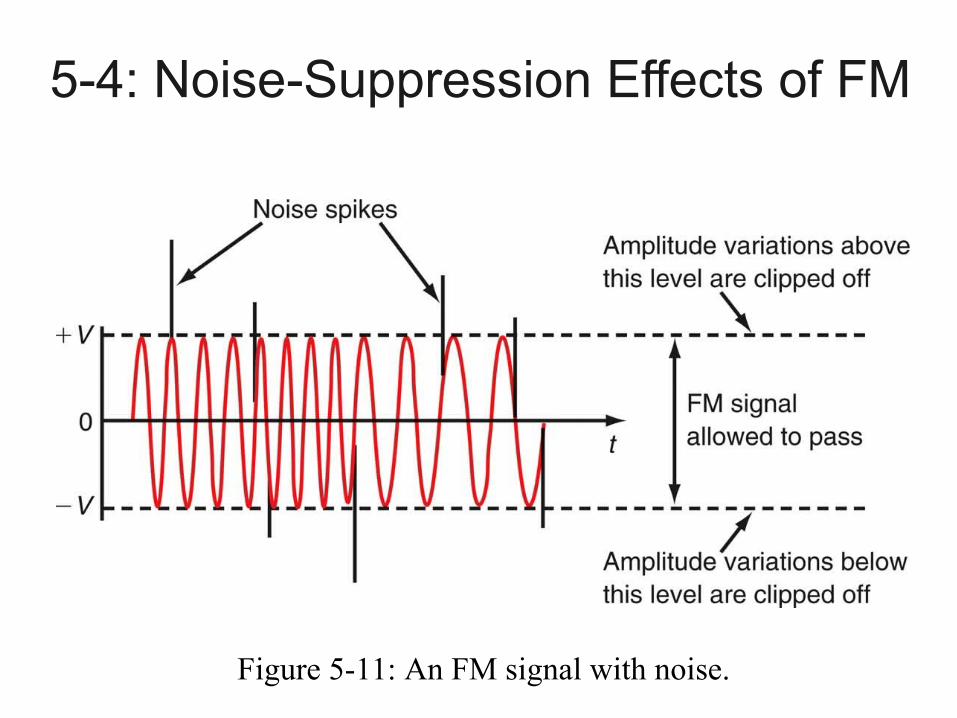
5-4: Noise-Suppression Effects of FM
Figure 5-11: An FM signal with noise.
5-4: Noise-Suppression Effects of FM
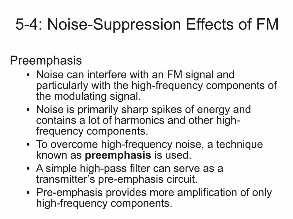
Preemphasis ● Noise can interfere with an FM signal and
particularly with the high-frequency components of the modulating signal.
● Noise is primarily sharp spikes of energy and contains a lot of harmonics and other high-frequency components.
● To overcome high-frequency noise, a technique known as preemphasis is used.
● A simple high-pass filter can serve as a transmitter’s pre-emphasis circuit.
● Pre-emphasis provides more amplification of only high-frequency components.
5-4: Noise-Suppression Effects of FM
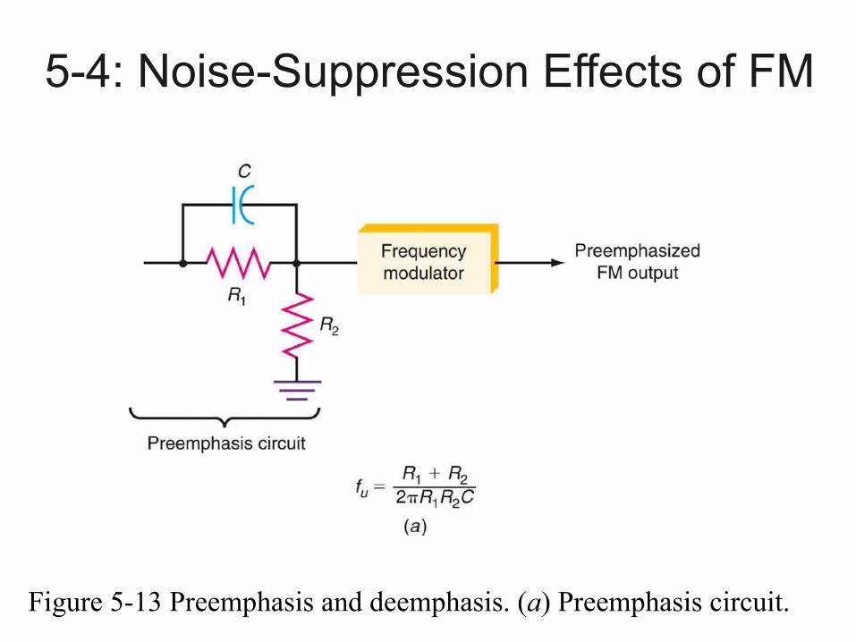
Figure 5-13 Preemphasis and deemphasis. (a) Preemphasis circuit.
5-4: Noise-Suppression Effects of FM
Preemphasis● A simple low-pass filter can operate as a
deemphasis circuit in a receiver.● A deemphasis circuit returns the frequency
response to its normal flat level.● The combined effect of preemphasis and
deemphasis is to increase the signal-to-noise ratio for the high-frequency components during transmission so that they will be stronger and not masked by noise.
5-4: Noise-Suppression Effects of FM
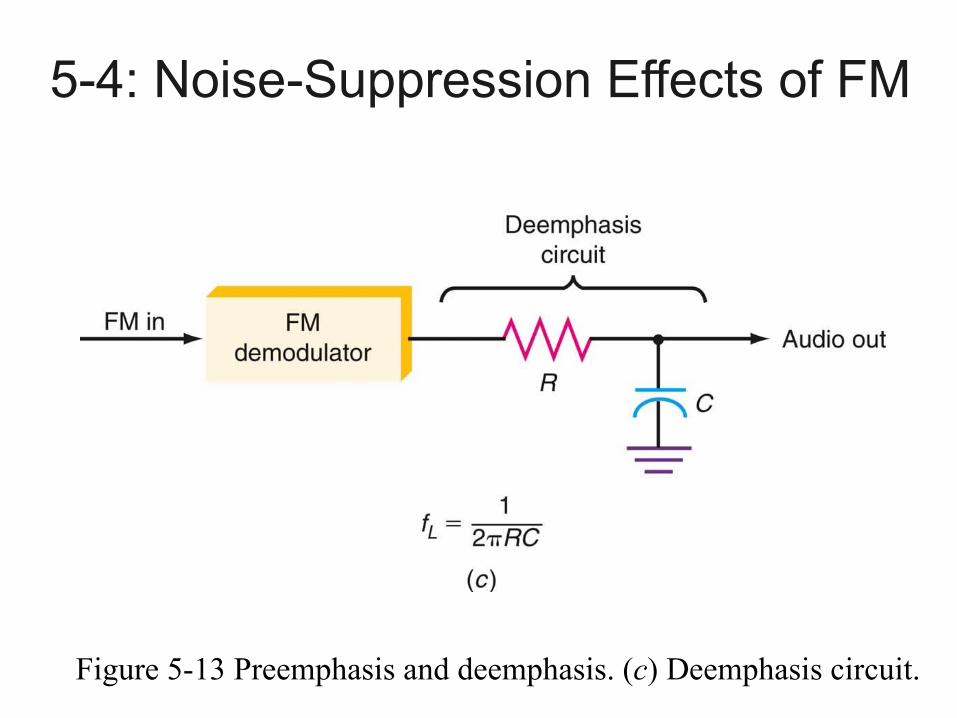
Figure 5-13 Preemphasis and deemphasis. (c) Deemphasis circuit.
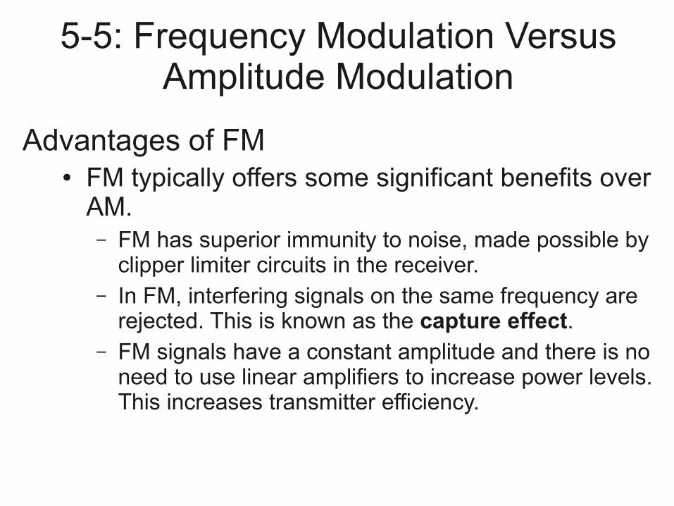
5-5: Frequency Modulation Versus Amplitude Modulation
Advantages of FM● FM typically offers some significant benefits over
AM.– FM has superior immunity to noise, made possible by
clipper limiter circuits in the receiver.– In FM, interfering signals on the same frequency are
rejected. This is known as the capture effect.– FM signals have a constant amplitude and there is no
need to use linear amplifiers to increase power levels. This increases transmitter efficiency.
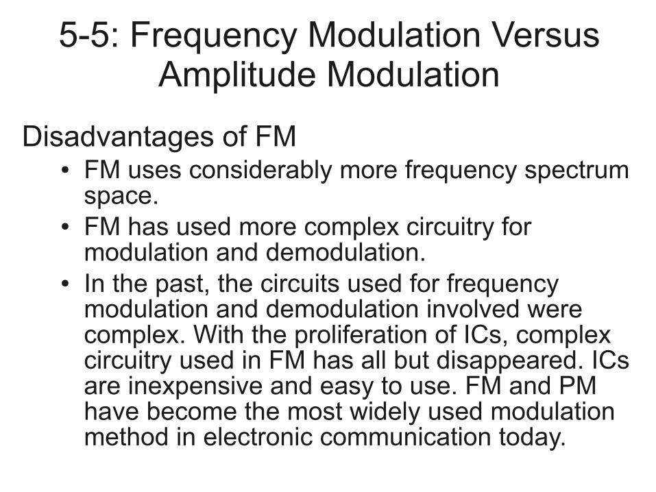
5-5: Frequency Modulation Versus Amplitude Modulation
Disadvantages of FM● FM uses considerably more frequency spectrum
space.● FM has used more complex circuitry for
modulation and demodulation.● In the past, the circuits used for frequency
modulation and demodulation involved were complex. With the proliferation of ICs, complex circuitry used in FM has all but disappeared. ICs are inexpensive and easy to use. FM and PM have become the most widely used modulation method in electronic communication today.
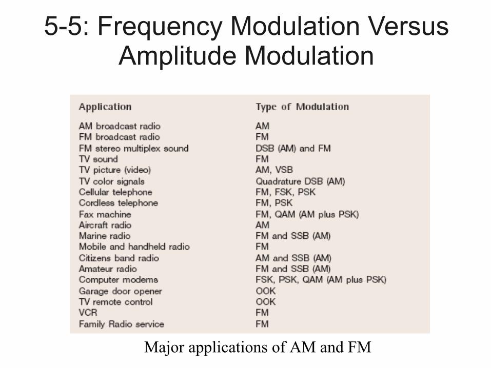
5-5: Frequency Modulation Versus Amplitude Modulation
Major applications of AM and FM
Example SOEC4.1PP117
● A 107.6 MHz carrier is frequency modulated by a 7 kHz sine wave. The resultant FM signal has a frequency deviation of 50 kHz.● a) Find the carrier swing of the FM signal.● b) Determine the highest and lowest frequencies
attained by the modulated signal.● c) What is the modulation index of FM wave.
Example SOEC4.2PP118
● Determine the frequency deviation and carrier swing for a frequency-modulated signal which has a resting frequency of 105.000 MHz and whose upper frequency is 105.007 MHz when modulated by a particular wave. Find the lowest frequency reached by the FM wave.
Example SOEC4.4PP120
● A frequency-modulated signal which is modulated by a 3 kHz sine wave reaches a maximum frequency of 100.02 MHz and minimum frequency of 99.98 MHz.● a) Determine the carrier swing.● b) Find the carrier frequency.● c) Calculate the frequency deviation of the
signal.● d) What is the modulation index of the signal?
Example
For an FM modulator with a modulation index m = 0.5, a modulating signal m(t)=Vmsin(24e3*pi*t) and unmodulated carrier c(t)=15sin(176.2e6*pi*t), determine:
Number of pairs of significant side frequencies. The relative amplitudes for the modulated
carrier and its side frequencies.
Example cont’d
● Draw and label appropriately the frequency spectrum.
● The actual minimum bandwidth using Bessel functions.
● The approximate minimum bandwidth using Carson’s rule.
● The unmodulated carrier power and total power in the angle-modulated wave assuming that the load resistance is 100 Ohm .
● Comment on the results of part (vi).