Embed Size (px)
Citation preview
Fundamentals of Electrical EngineeringProf. Debapriya Das
Department of Electrical EngineeringIndian Institute of Technology, Kharagpur
Lecture – 58Three phase Induction Motors
So next we will be you know in another example other 3 or 4 examples and with that we
will close the single phase transformer right.
(Refer Slide Time: 00:27)
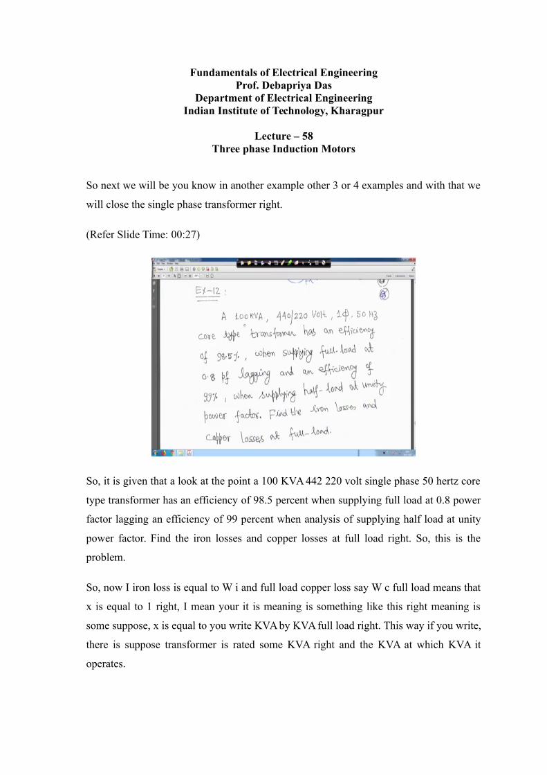
So, it is given that a look at the point a 100 KVA 442 220 volt single phase 50 hertz core
type transformer has an efficiency of 98.5 percent when supplying full load at 0.8 power
factor lagging an efficiency of 99 percent when analysis of supplying half load at unity
power factor. Find the iron losses and copper losses at full load right. So, this is the
problem.
So, now I iron loss is equal to W i and full load copper loss say W c full load means that
x is equal to 1 right, I mean your it is meaning is something like this right meaning is
some suppose, x is equal to you write KVA by KVA full load right. This way if you write,
there is suppose transformer is rated some KVA right and the KVA at which KVA it
operates.
So, ratio of these thing will give you the your x right the loading factor say. So, if it is
KVA is equal to KVA fl then x is equal to 1. So, that is why it is written here x is equal to
1 right.
(Refer Slide Time: 01:42)
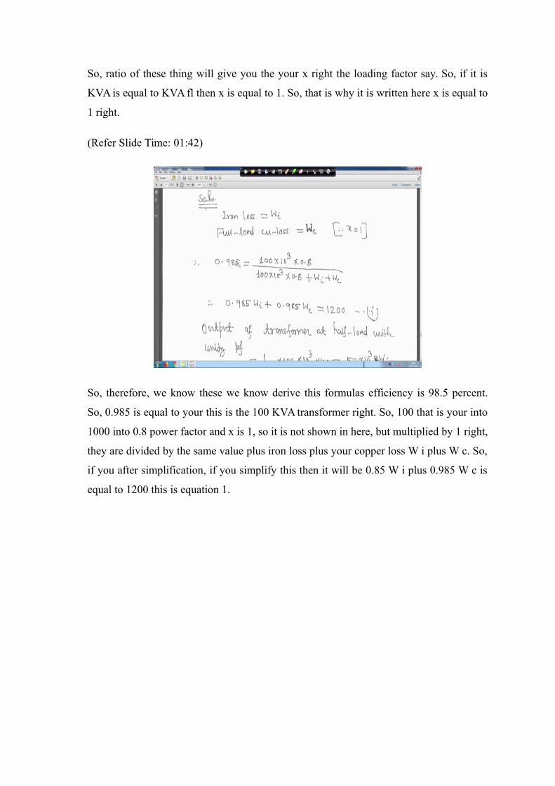
So, therefore, we know these we know derive this formulas efficiency is 98.5 percent.
So, 0.985 is equal to your this is the 100 KVA transformer right. So, 100 that is your into
1000 into 0.8 power factor and x is 1, so it is not shown in here, but multiplied by 1 right,
they are divided by the same value plus iron loss plus your copper loss W i plus W c. So,
if you after simplification, if you simplify this then it will be 0.85 W i plus 0.985 W c is
equal to 1200 this is equation 1.
(Refer Slide Time: 02:18)
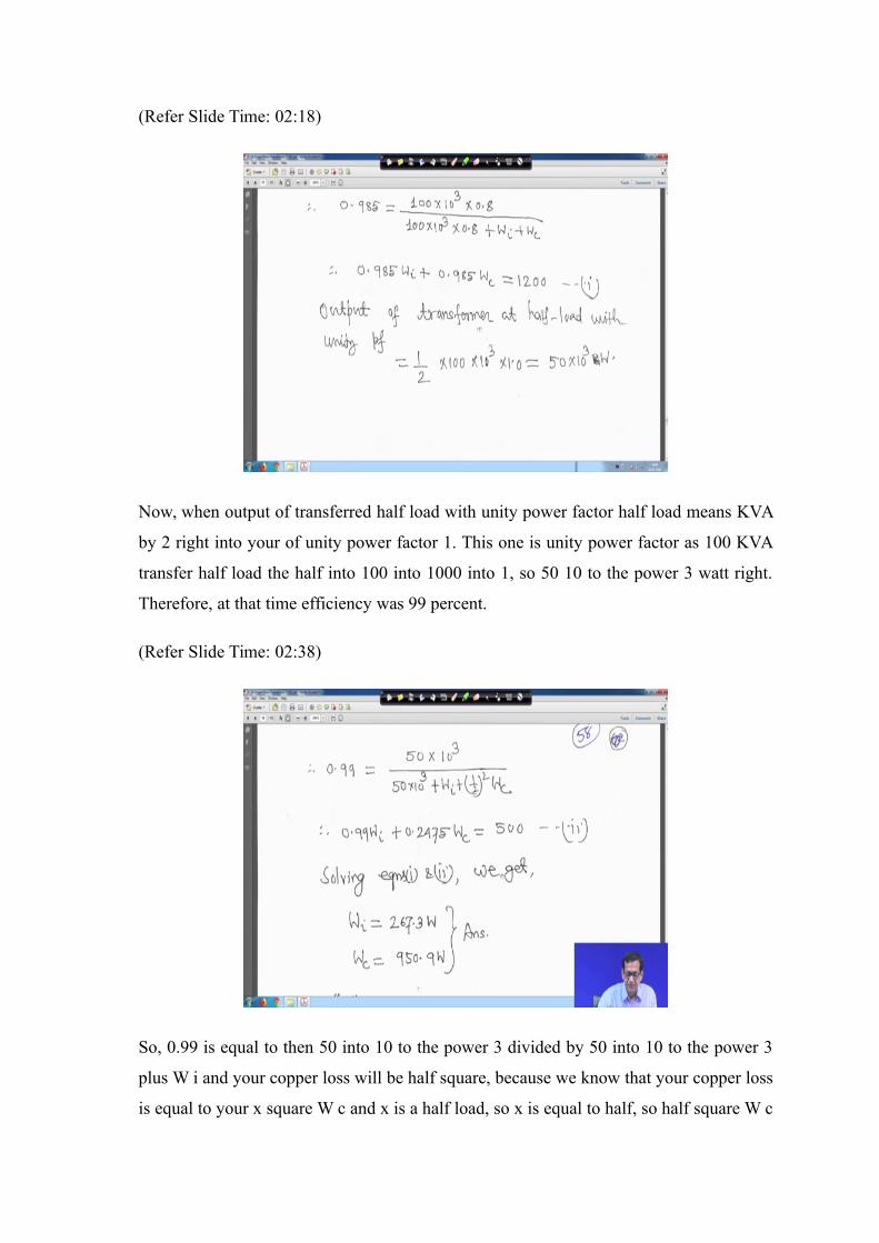
Now, when output of transferred half load with unity power factor half load means KVA
by 2 right into your of unity power factor 1. This one is unity power factor as 100 KVA
transfer half load the half into 100 into 1000 into 1, so 50 10 to the power 3 watt right.
Therefore, at that time efficiency was 99 percent.
(Refer Slide Time: 02:38)
So, 0.99 is equal to then 50 into 10 to the power 3 divided by 50 into 10 to the power 3
plus W i and your copper loss will be half square, because we know that your copper loss
is equal to your x square W c and x is a half load, so x is equal to half, so half square W c
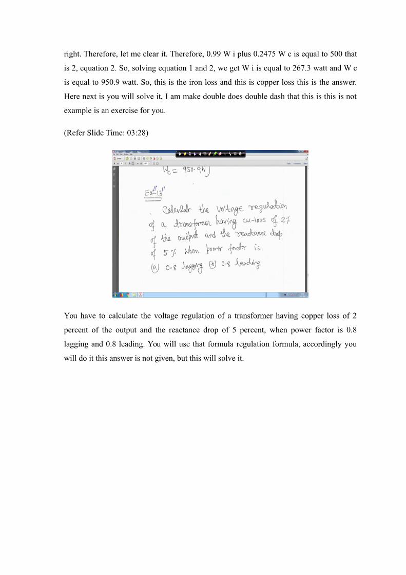
right. Therefore, let me clear it. Therefore, 0.99 W i plus 0.2475 W c is equal to 500 that
is 2, equation 2. So, solving equation 1 and 2, we get W i is equal to 267.3 watt and W c
is equal to 950.9 watt. So, this is the iron loss and this is copper loss this is the answer.
Here next is you will solve it, I am make double does double dash that this is this is not
example is an exercise for you.
(Refer Slide Time: 03:28)
You have to calculate the voltage regulation of a transformer having copper loss of 2
percent of the output and the reactance drop of 5 percent, when power factor is 0.8
lagging and 0.8 leading. You will use that formula regulation formula, accordingly you
will do it this answer is not given, but this will solve it.
(Refer Slide Time: 03:48)
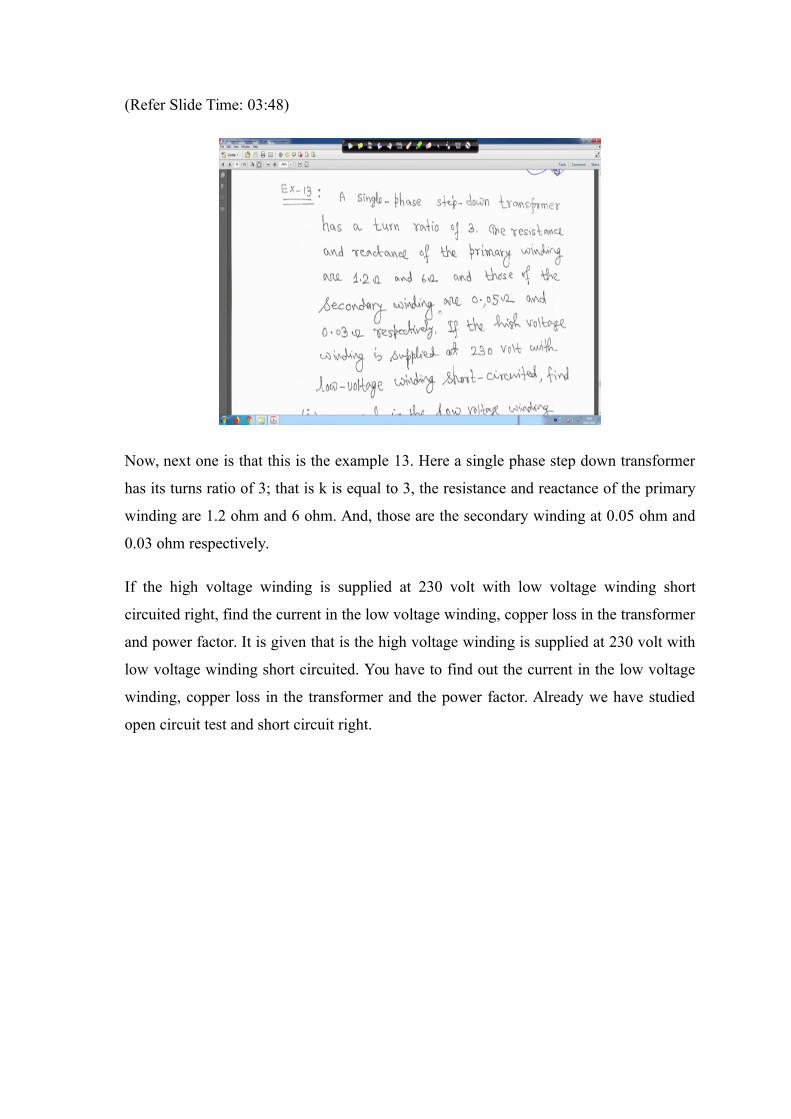
Now, next one is that this is the example 13. Here a single phase step down transformer
has its turns ratio of 3; that is k is equal to 3, the resistance and reactance of the primary
winding are 1.2 ohm and 6 ohm. And, those are the secondary winding at 0.05 ohm and
0.03 ohm respectively.
If the high voltage winding is supplied at 230 volt with low voltage winding short
circuited right, find the current in the low voltage winding, copper loss in the transformer
and power factor. It is given that is the high voltage winding is supplied at 230 volt with
low voltage winding short circuited. You have to find out the current in the low voltage
winding, copper loss in the transformer and the power factor. Already we have studied
open circuit test and short circuit right.
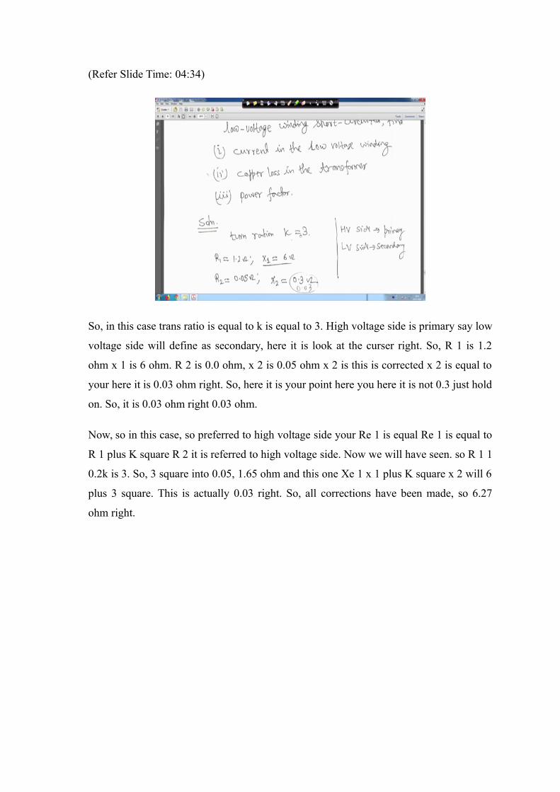
(Refer Slide Time: 04:34)
So, in this case trans ratio is equal to k is equal to 3. High voltage side is primary say low
voltage side will define as secondary, here it is look at the curser right. So, R 1 is 1.2
ohm x 1 is 6 ohm. R 2 is 0.0 ohm, x 2 is 0.05 ohm x 2 is this is corrected x 2 is equal to
your here it is 0.03 ohm right. So, here it is your point here you here it is not 0.3 just hold
on. So, it is 0.03 ohm right 0.03 ohm.
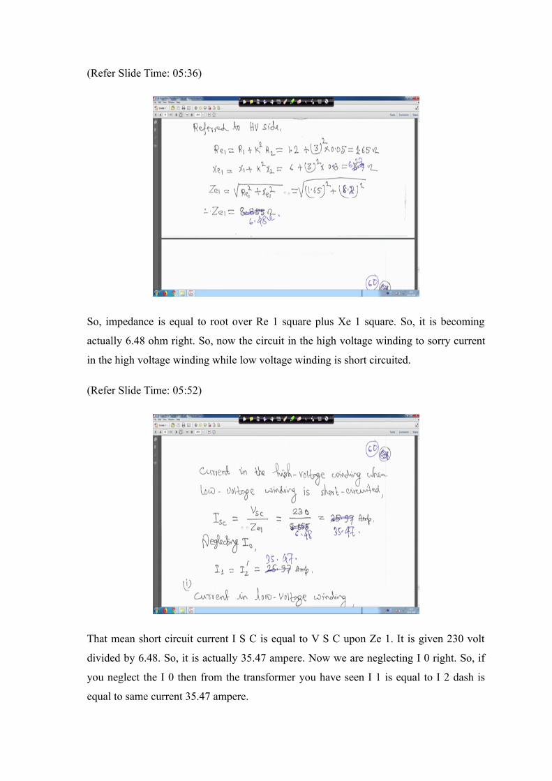
Now, so in this case, so preferred to high voltage side your Re 1 is equal Re 1 is equal to
R 1 plus K square R 2 it is referred to high voltage side. Now we will have seen. so R 1 1
0.2k is 3. So, 3 square into 0.05, 1.65 ohm and this one Xe 1 x 1 plus K square x 2 will 6
plus 3 square. This is actually 0.03 right. So, all corrections have been made, so 6.27
ohm right.
(Refer Slide Time: 05:36)
So, impedance is equal to root over Re 1 square plus Xe 1 square. So, it is becoming
actually 6.48 ohm right. So, now the circuit in the high voltage winding to sorry current
in the high voltage winding while low voltage winding is short circuited.
(Refer Slide Time: 05:52)
That mean short circuit current I S C is equal to V S C upon Ze 1. It is given 230 volt
divided by 6.48. So, it is actually 35.47 ampere. Now we are neglecting I 0 right. So, if
you neglect the I 0 then from the transformer you have seen I 1 is equal to I 2 dash is
equal to same current 35.47 ampere.
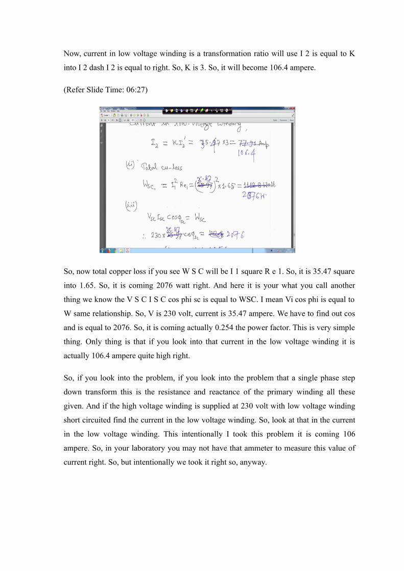
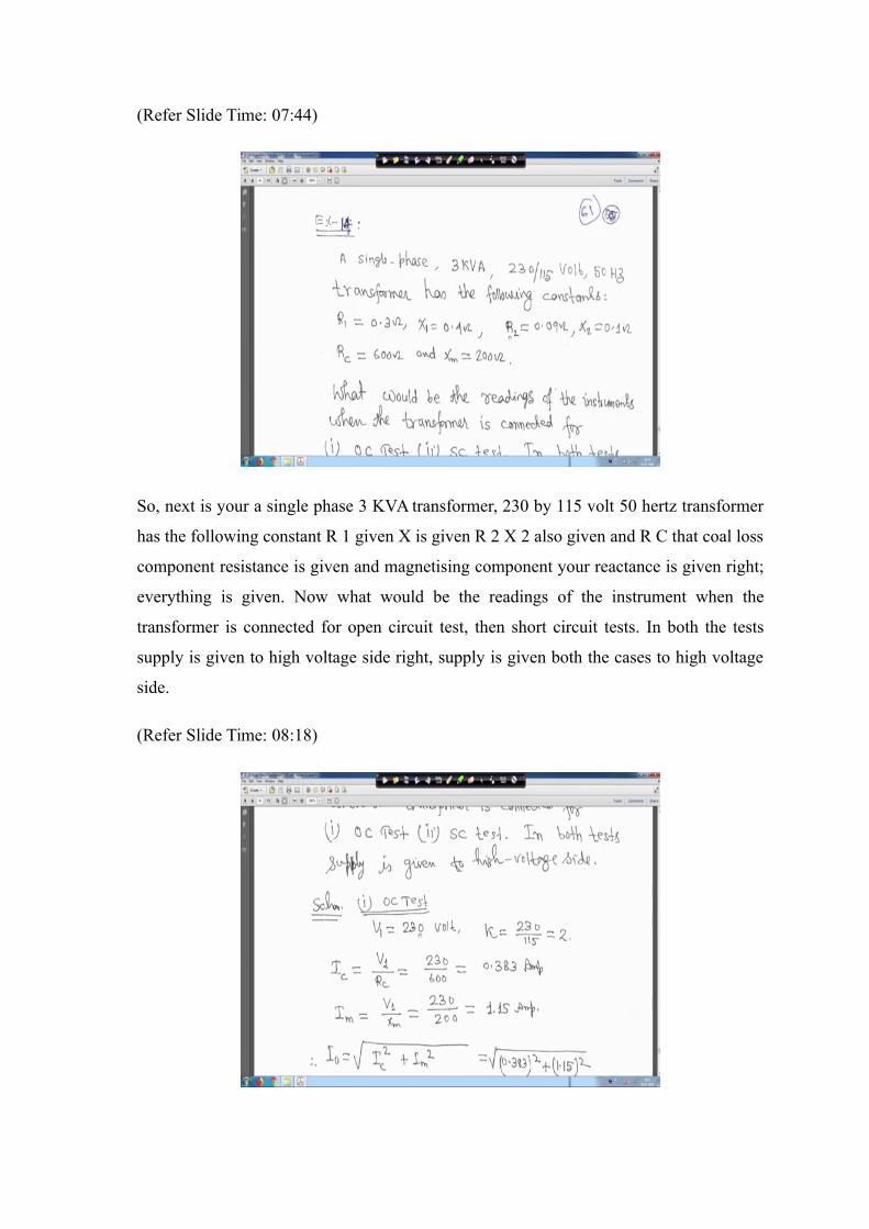
Now, current in low voltage winding is a transformation ratio will use I 2 is equal to K
into I 2 dash I 2 is equal to right. So, K is 3. So, it will become 106.4 ampere.
(Refer Slide Time: 06:27)
So, now total copper loss if you see W S C will be I 1 square R e 1. So, it is 35.47 square
into 1.65. So, it is coming 2076 watt right. And here it is your what you call another
thing we know the V S C I S C cos phi sc is equal to WSC. I mean Vi cos phi is equal to
W same relationship. So, V is 230 volt, current is 35.47 ampere. We have to find out cos
and is equal to 2076. So, it is coming actually 0.254 the power factor. This is very simple
thing. Only thing is that if you look into that current in the low voltage winding it is
actually 106.4 ampere quite high right.
So, if you look into the problem, if you look into the problem that a single phase step
down transform this is the resistance and reactance of the primary winding all these
given. And if the high voltage winding is supplied at 230 volt with low voltage winding
short circuited find the current in the low voltage winding. So, look at that in the current
in the low voltage winding. This intentionally I took this problem it is coming 106
ampere. So, in your laboratory you may not have that ammeter to measure this value of
current right. So, but intentionally we took it right so, anyway.
(Refer Slide Time: 07:44)
So, next is your a single phase 3 KVA transformer, 230 by 115 volt 50 hertz transformer
has the following constant R 1 given X is given R 2 X 2 also given and R C that coal loss
component resistance is given and magnetising component your reactance is given right;
everything is given. Now what would be the readings of the instrument when the
transformer is connected for open circuit test, then short circuit tests. In both the tests
supply is given to high voltage side right, supply is given both the cases to high voltage
side.
(Refer Slide Time: 08:18)
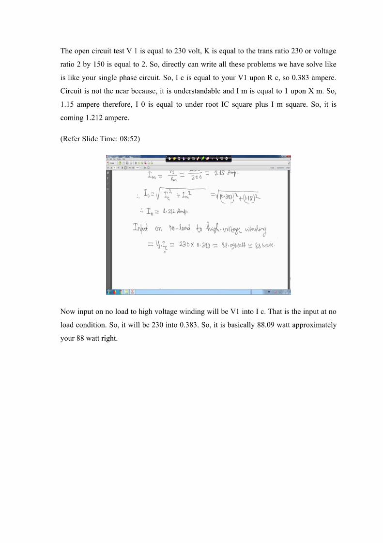
The open circuit test V 1 is equal to 230 volt, K is equal to the trans ratio 230 or voltage
ratio 2 by 150 is equal to 2. So, directly can write all these problems we have solve like
is like your single phase circuit. So, I c is equal to your V1 upon R c, so 0.383 ampere.
Circuit is not the near because, it is understandable and I m is equal to 1 upon X m. So,
1.15 ampere therefore, I 0 is equal to under root IC square plus I m square. So, it is
coming 1.212 ampere.
(Refer Slide Time: 08:52)
Now input on no load to high voltage winding will be V1 into I c. That is the input at no
load condition. So, it will be 230 into 0.383. So, it is basically 88.09 watt approximately
your 88 watt right.
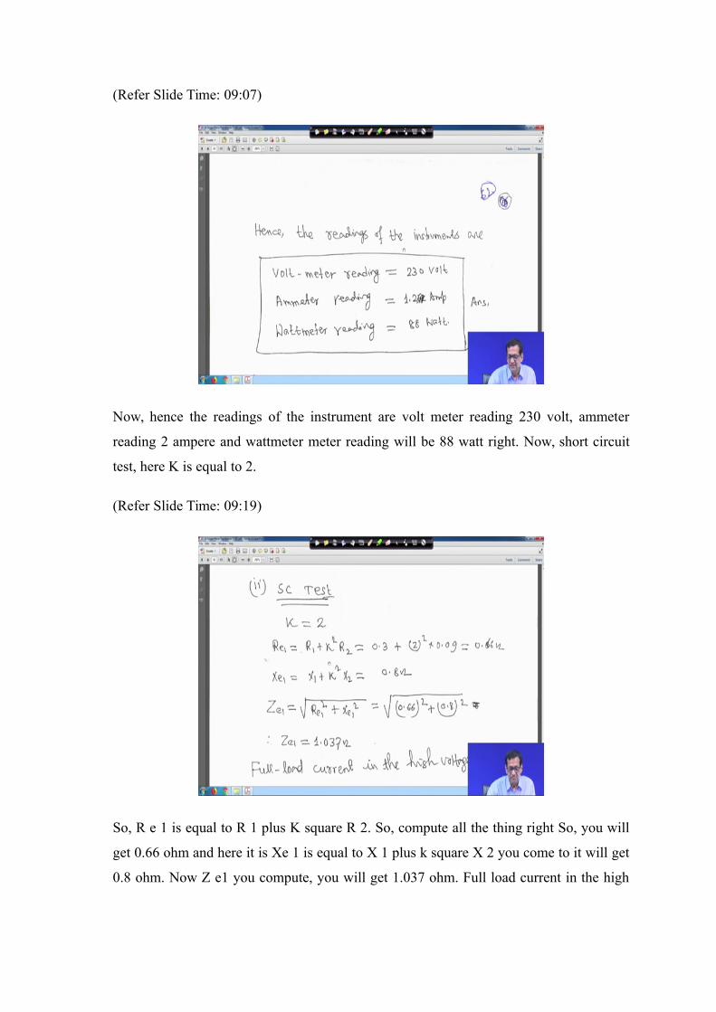
(Refer Slide Time: 09:07)
Now, hence the readings of the instrument are volt meter reading 230 volt, ammeter
reading 2 ampere and wattmeter meter reading will be 88 watt right. Now, short circuit
test, here K is equal to 2.
(Refer Slide Time: 09:19)
So, R e 1 is equal to R 1 plus K square R 2. So, compute all the thing right So, you will
get 0.66 ohm and here it is Xe 1 is equal to X 1 plus k square X 2 you come to it will get
0.8 ohm. Now Z e1 you compute, you will get 1.037 ohm. Full load current in the high
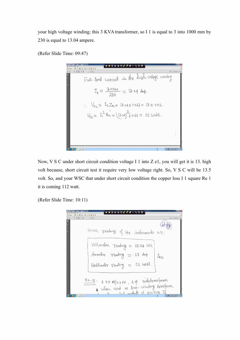
your high voltage winding; this 3 KVA transformer, so I 1 is equal to 3 into 1000 mm by
230 is equal to 13.04 ampere.
(Refer Slide Time: 09:47)
Now, V S C under short circuit condition voltage I 1 into Z e1, you will get it is 13. high
volt because, short circuit test it require very low voltage right. So, V S C will be 13.5
volt. So, and your WSC that under short circuit condition the copper loss I 1 square Re 1
it is coming 112 watt.
(Refer Slide Time: 10:11)
So, therefore, the reading of the instrumental are voltmeter reading will be 13.5 volt,
ammeter reading will be 13 ampere and watt metre reading will be 112 watt right. So,
your the this is the last problem I think for the transformer. It is an auto transformer now
these are very simple thing.
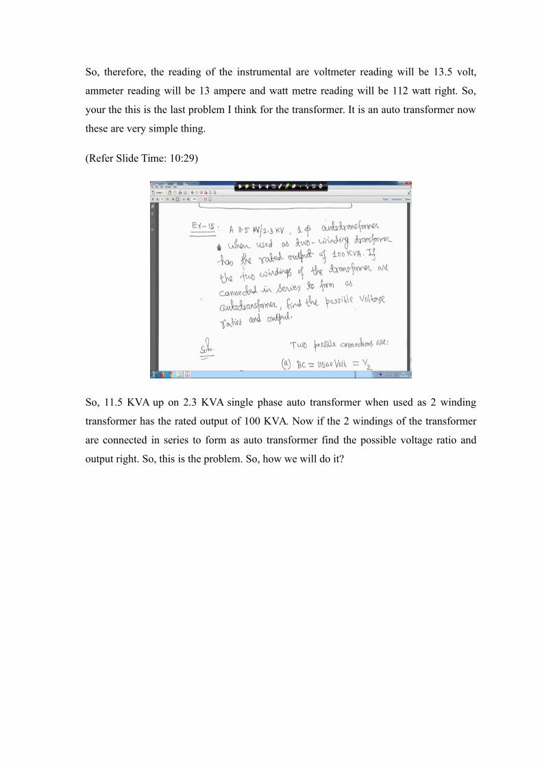
(Refer Slide Time: 10:29)
So, 11.5 KVA up on 2.3 KVA single phase auto transformer when used as 2 winding
transformer has the rated output of 100 KVA. Now if the 2 windings of the transformer
are connected in series to form as auto transformer find the possible voltage ratio and
output right. So, this is the problem. So, how we will do it?
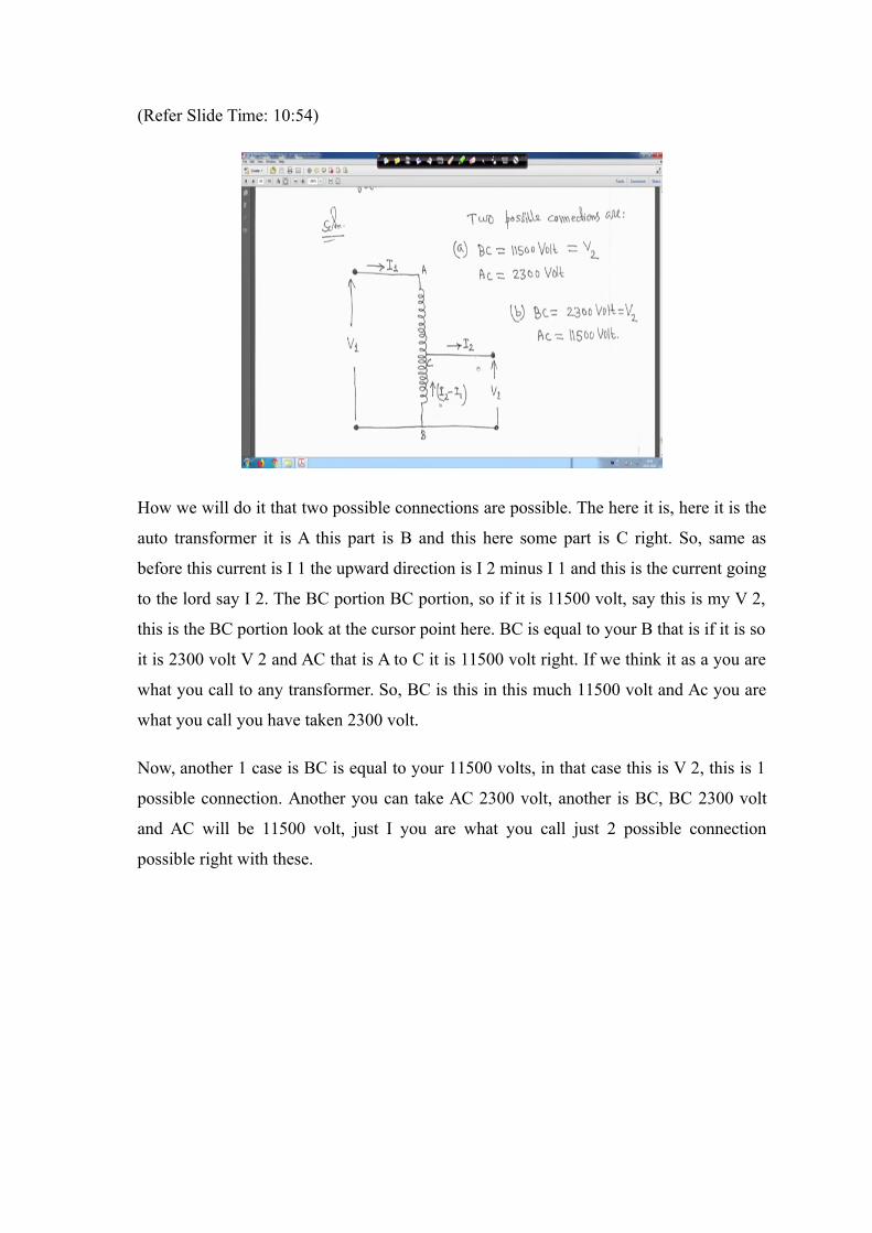
(Refer Slide Time: 10:54)
How we will do it that two possible connections are possible. The here it is, here it is the
auto transformer it is A this part is B and this here some part is C right. So, same as
before this current is I 1 the upward direction is I 2 minus I 1 and this is the current going
to the lord say I 2. The BC portion BC portion, so if it is 11500 volt, say this is my V 2,
this is the BC portion look at the cursor point here. BC is equal to your B that is if it is so
it is 2300 volt V 2 and AC that is A to C it is 11500 volt right. If we think it as a you are
what you call to any transformer. So, BC is this in this much 11500 volt and Ac you are
what you call you have taken 2300 volt.
Now, another 1 case is BC is equal to your 11500 volts, in that case this is V 2, this is 1
possible connection. Another you can take AC 2300 volt, another is BC, BC 2300 volt
and AC will be 11500 volt, just I you are what you call just 2 possible connection
possible right with these.
(Refer Slide Time: 12:03)
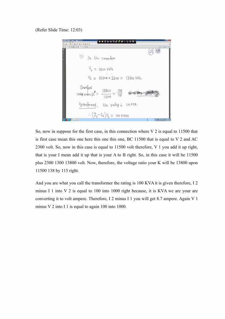
So, now in suppose for the first case, in this connection where V 2 is equal to 11500 that
is first case mean this one here this one this one, BC 11500 that is equal to V 2 and AC
2300 volt. So, now in this case is equal to 11500 volt therefore, V 1 you add it up right,
that is your I mean add it up that is your A to B right. So, in this case it will be 11500
plus 2300 1300 13800 volt. Now, therefore, the voltage ratio your K will be 13800 upon
11500 138 by 115 right.
And you are what you call the transformer the rating is 100 KVA it is given therefore, I 2
minus I 1 into V 2 is equal to 100 into 1000 right because, it is KVA we are your are
converting it to volt ampere. Therefore, I 2 minus I 1 you will get 8.7 ampere. Again V 1
minus V 2 into I 1 is equal to again 100 into 1000.
(Refer Slide Time: 13:02)
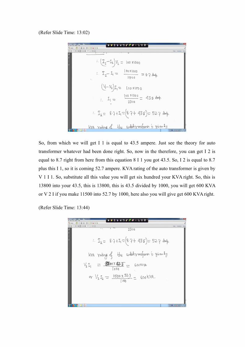
So, from which we will get I 1 is equal to 43.5 ampere. Just see the theory for auto
transformer whatever had been done right. So, now in the therefore, you can get I 2 is
equal to 8.7 right from here from this equation 8 I 1 you got 43.5. So, I 2 is equal to 8.7
plus this I 1, so it is coming 52.7 ampere. KVA rating of the auto transformer is given by
V 1 I 1. So, substitute all this value you will get six hundred your KVA right. So, this is
13800 into your 43.5, this is 13800, this is 43.5 divided by 1000, you will get 600 KVA
or V 2 I if you make 11500 into 52.7 by 1000, here also you will give get 600 KVA right.
(Refer Slide Time: 13:44)
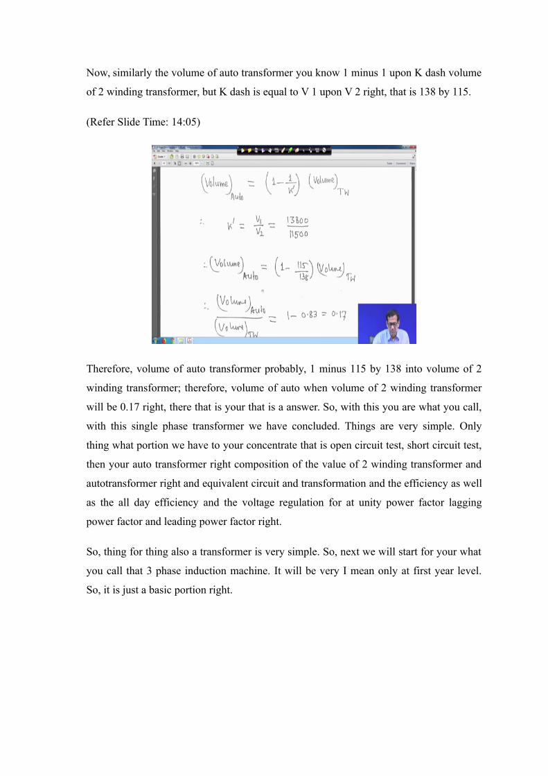
Now, similarly the volume of auto transformer you know 1 minus 1 upon K dash volume
of 2 winding transformer, but K dash is equal to V 1 upon V 2 right, that is 138 by 115.
(Refer Slide Time: 14:05)
Therefore, volume of auto transformer probably, 1 minus 115 by 138 into volume of 2
winding transformer; therefore, volume of auto when volume of 2 winding transformer
will be 0.17 right, there that is your that is a answer. So, with this you are what you call,
with this single phase transformer we have concluded. Things are very simple. Only
thing what portion we have to your concentrate that is open circuit test, short circuit test,
then your auto transformer right composition of the value of 2 winding transformer and
autotransformer right and equivalent circuit and transformation and the efficiency as well
as the all day efficiency and the voltage regulation for at unity power factor lagging
power factor and leading power factor right.
So, thing for thing also a transformer is very simple. So, next we will start for your what
you call that 3 phase induction machine. It will be very I mean only at first year level.
So, it is just a basic portion right.
(Refer Slide Time: 15:07)
So, so 3 phase induction motor will start. So, it is actually what particularly as at the
basic level only little bit will be covered right. And just see how is it and before making
this you are what you call 3 phase induction motor, I will tell at the beginning that
whenever you will study this in your college, see the your laboratory that an open
induction machine wound rotor induction machine as well as squirrel cage induction
motor both wound rotor as well as squirrel cage induction motor it is open things see that
stator part see the you are what you call the rotor part because, from here with diagram
you may perhaps visualization will be slightly you know based on your imagination. But,
in the laboratory definitely you have that your stator open starter open rotor separately
such that, you can see on your eyes that exactly what it is right.
So, this is the thing, we will go for single phase transformer. So, hopefully that basic
principle of that your induction machine a hope it will not create any problem for you.
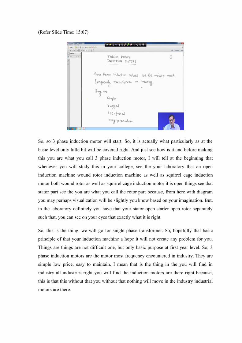
Things are things are not difficult one, but only basic purpose at first year level. So, 3
phase induction motors are the motor most frequency encountered in industry. They are
simple low price, easy to maintain. I mean that is the thing in the you will find in
industry all industries right you will find the induction motors are there right because,
this is that this without that you without that nothing will move in the industry industrial
motors are there.
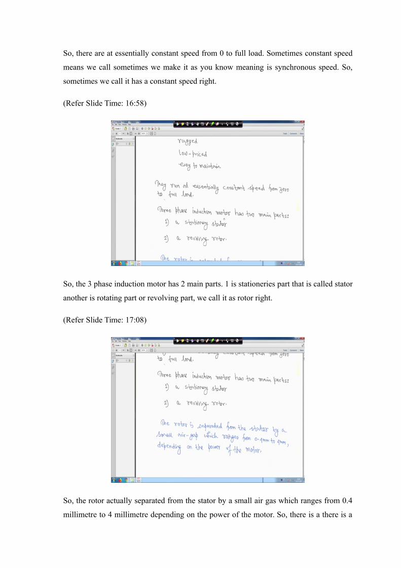
So, there are at essentially constant speed from 0 to full load. Sometimes constant speed
means we call sometimes we make it as you know meaning is synchronous speed. So,
sometimes we call it has a constant speed right.
(Refer Slide Time: 16:58)
So, the 3 phase induction motor has 2 main parts. 1 is stationeries part that is called stator
another is rotating part or revolving part, we call it as rotor right.
(Refer Slide Time: 17:08)
So, the rotor actually separated from the stator by a small air gas which ranges from 0.4
millimetre to 4 millimetre depending on the power of the motor. So, there is a there is a
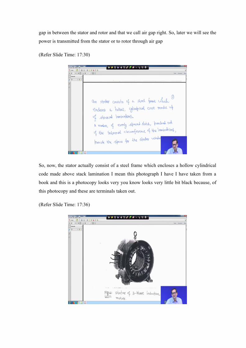
gap in between the stator and rotor and that we call air gap right. So, later we will see the
power is transmitted from the stator or to rotor through air gap
(Refer Slide Time: 17:30)
So, now, the stator actually consist of a steel frame which encloses a hollow cylindrical
code made above stack lamination I mean this photograph I have I have taken from a
book and this is a photocopy looks very you know looks very little bit black because, of
this photocopy and these are terminals taken out.
(Refer Slide Time: 17:36)
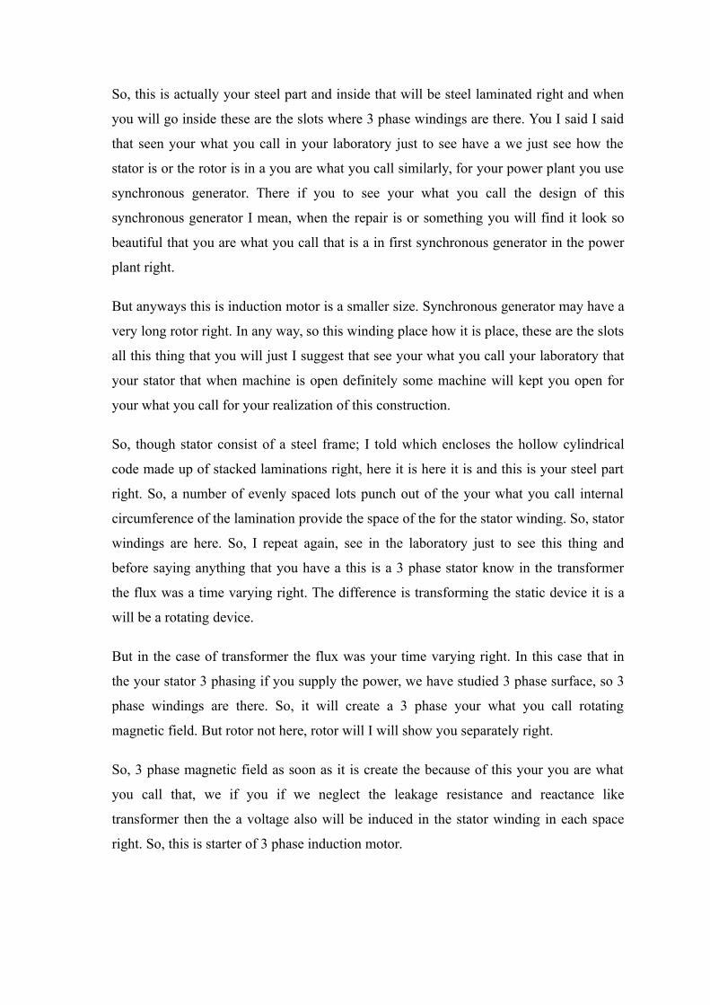
So, this is actually your steel part and inside that will be steel laminated right and when
you will go inside these are the slots where 3 phase windings are there. You I said I said
that seen your what you call in your laboratory just to see have a we just see how the
stator is or the rotor is in a you are what you call similarly, for your power plant you use
synchronous generator. There if you to see your what you call the design of this
synchronous generator I mean, when the repair is or something you will find it look so
beautiful that you are what you call that is a in first synchronous generator in the power
plant right.
But anyways this is induction motor is a smaller size. Synchronous generator may have a
very long rotor right. In any way, so this winding place how it is place, these are the slots
all this thing that you will just I suggest that see your what you call your laboratory that
your stator that when machine is open definitely some machine will kept you open for
your what you call for your realization of this construction.
So, though stator consist of a steel frame; I told which encloses the hollow cylindrical
code made up of stacked laminations right, here it is here it is and this is your steel part
right. So, a number of evenly spaced lots punch out of the your what you call internal
circumference of the lamination provide the space of the for the stator winding. So, stator
windings are here. So, I repeat again, see in the laboratory just to see this thing and
before saying anything that you have a this is a 3 phase stator know in the transformer
the flux was a time varying right. The difference is transforming the static device it is a
will be a rotating device.
But in the case of transformer the flux was your time varying right. In this case that in
the your stator 3 phasing if you supply the power, we have studied 3 phase surface, so 3
phase windings are there. So, it will create a 3 phase your what you call rotating
magnetic field. But rotor not here, rotor will I will show you separately right.
So, 3 phase magnetic field as soon as it is create the because of this your you are what
you call that, we if you if we neglect the leakage resistance and reactance like
transformer then the a voltage also will be induced in the stator winding in each space
right. So, this is starter of 3 phase induction motor.
(Refer Slide Time: 20:09)
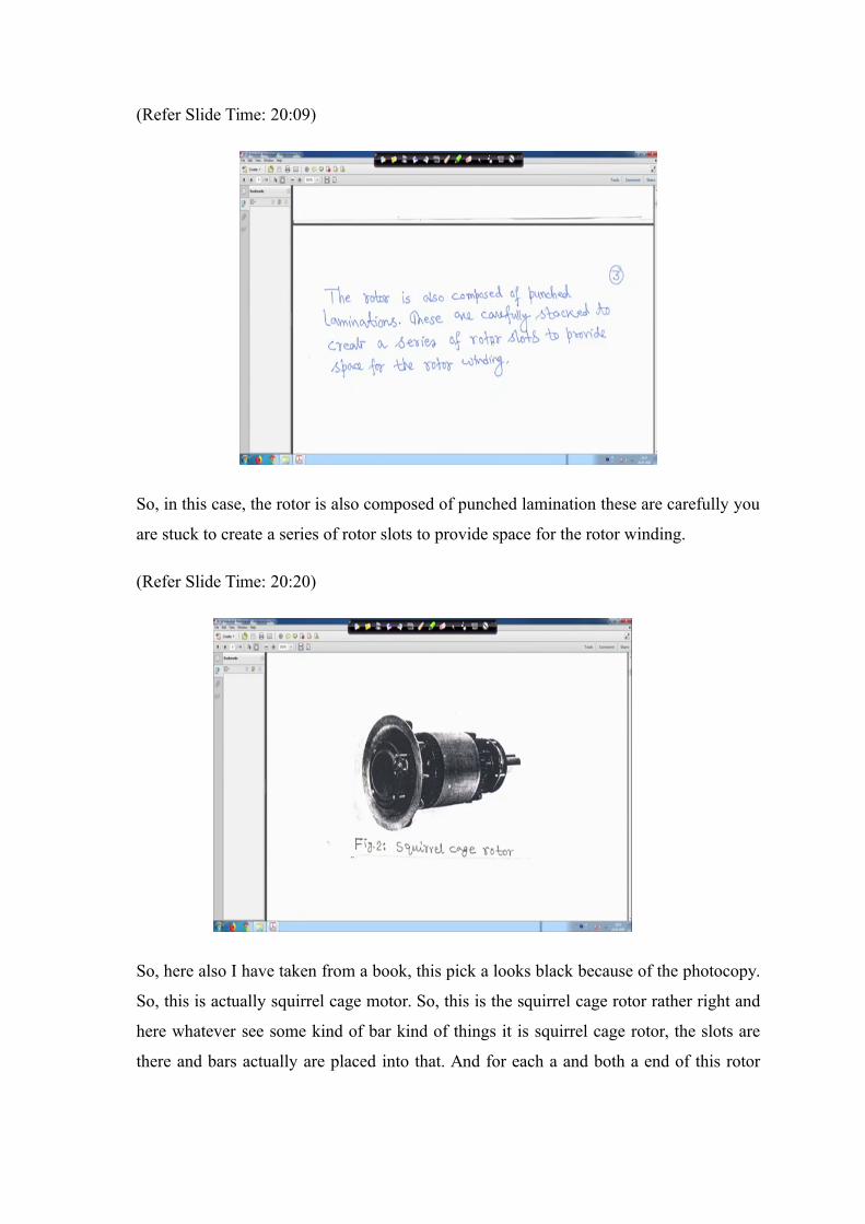
So, in this case, the rotor is also composed of punched lamination these are carefully you
are stuck to create a series of rotor slots to provide space for the rotor winding.
(Refer Slide Time: 20:20)
So, here also I have taken from a book, this pick a looks black because of the photocopy.
So, this is actually squirrel cage motor. So, this is the squirrel cage rotor rather right and
here whatever see some kind of bar kind of things it is squirrel cage rotor, the slots are
there and bars actually are placed into that. And for each a and both a end of this rotor
actually you are what you call it is welded by at copper this because, this is made of your
what you call cropper.
So, both sides are you are you are what you call you punch together and welded such
that, it is short circuit is itself. So, why we will see later, so this is squirrel cage rotor. I
suggest in your laboratory see the open induction machine, definitely it will be there
right. There thus that you can have a better visualisation.
(Refer Slide Time: 21:10)
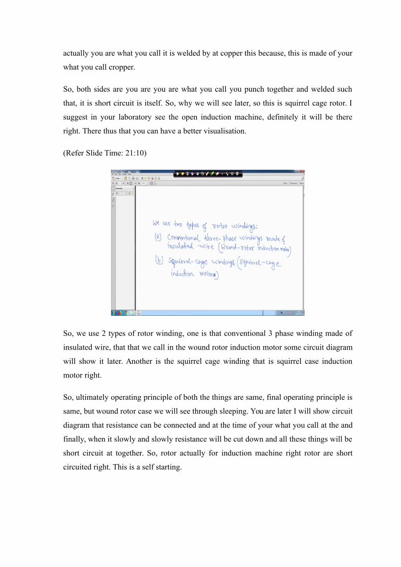
So, we use 2 types of rotor winding, one is that conventional 3 phase winding made of
insulated wire, that that we call in the wound rotor induction motor some circuit diagram
will show it later. Another is the squirrel cage winding that is squirrel case induction
motor right.
So, ultimately operating principle of both the things are same, final operating principle is
same, but wound rotor case we will see through sleeping. You are later I will show circuit
diagram that resistance can be connected and at the time of your what you call at the and
finally, when it slowly and slowly resistance will be cut down and all these things will be
short circuit at together. So, rotor actually for induction machine right rotor are short
circuited right. This is a self starting.
(Refer Slide Time: 22:00)
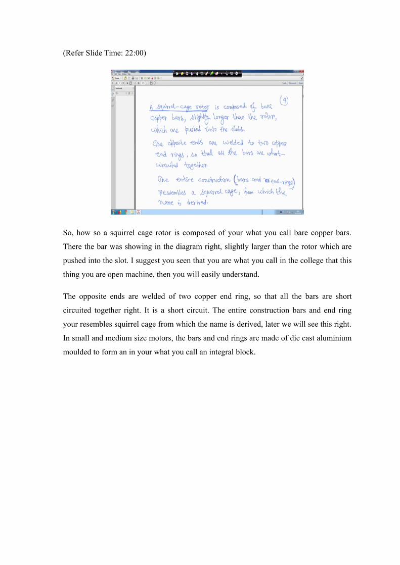
So, how so a squirrel cage rotor is composed of your what you call bare copper bars.
There the bar was showing in the diagram right, slightly larger than the rotor which are
pushed into the slot. I suggest you seen that you are what you call in the college that this
thing you are open machine, then you will easily understand.
The opposite ends are welded of two copper end ring, so that all the bars are short
circuited together right. It is a short circuit. The entire construction bars and end ring
your resembles squirrel cage from which the name is derived, later we will see this right.
In small and medium size motors, the bars and end rings are made of die cast aluminium
moulded to form an in your what you call an integral block.
(Refer Slide Time: 22:43)
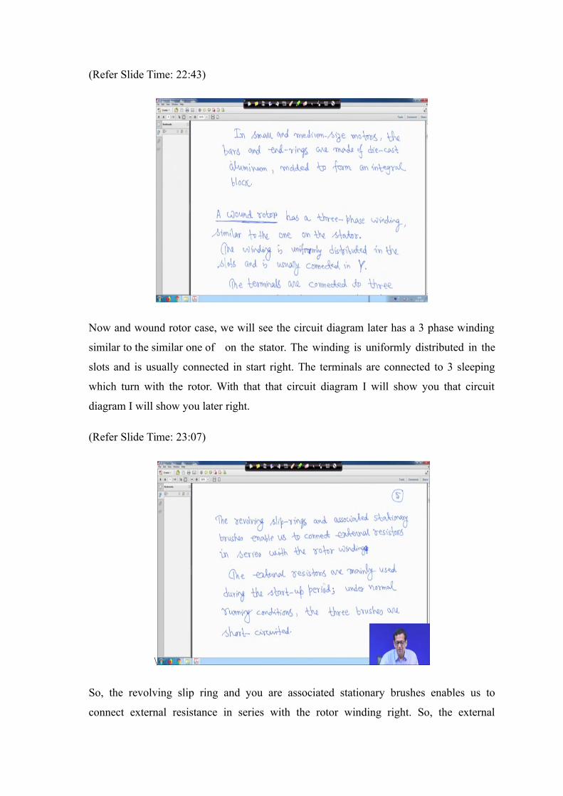
Now and wound rotor case, we will see the circuit diagram later has a 3 phase winding
similar to the similar one of on the stator. The winding is uniformly distributed in the
slots and is usually connected in start right. The terminals are connected to 3 sleeping
which turn with the rotor. With that that circuit diagram I will show you that circuit
diagram I will show you later right.
(Refer Slide Time: 23:07)
\
So, the revolving slip ring and you are associated stationary brushes enables us to
connect external resistance in series with the rotor winding right. So, the external
resistors are actually mainly used during the start up period under normal running
condition the three brushes are short circuited right. Under normal running condition the
3 brushes are short circuited.
So, when you do experiment particularly in your second or third year induction machine
experiment, at that time wound rotor machine definitely we will see. So, when we will
do the laboratory experiment at that time you can see this, but I am not sure whether you
will do the same experiment of first year or not right. So, but these are the thing, but if
your pure electrical engineer, then you will definitely see it in your second year or third
year electrical machine laboratory.
(Refer Slide Time: 23:53)
Right with this; thank you very much, we will be back again.