Embed Size (px)
Citation preview

Problems 499
11.74 A 120-V rms 60-Hz source supplies two loads connected in parallel, as shown in Fig. 11.89.
(a) Find the power factor of the parallel combination.
(b) Calculate the value of the capacitance connected in parallel that will raise the power factor to unity.
Figure 11.89For Prob. 11.74.
11.77 What is the reading of the wattmeter in the networkof Fig. 11.92?
Figure 11.92For Prob. 11.77.
11.78 Find the wattmeter reading of the circuit shown in Fig. 11.93.
11.75 Consider the power system shown in Fig. 11.90. Calculate:
(a) the total complex power
(b) the power factor Figure 11.93For Prob. 11.78.
Figure 11.90For Prob. 11.75.
11.79 Determine the wattmeter reading of the circuit in Fig. 11.94.
20 Q
Figure 11.94For Prob. 11.79.
Section 11.9 Applications
11.76 Obtain the w attmeter reading of the circuit in Fig. 11.91.
11.80 The circuit of Fig. 11.95 portrays a wattmeter connected into an ac network.
(a) Find the load current.
(b) Calculate the wattmeter readins.
3° A
Figure 11.91For Prob. 11.76. For Prob. 11.80.
500 Chapter 11 AC Power Analysis
11.81 Design a problem to help other students better understand e C d how to correct power factor to values other than unity.
11.82 A 240-V rms 60-Hz source supplies a parallel combination of a 5-kW heater and a 30-kVA induction motor whose power factor is 0.82. Determine:
(a) the system apparent power
(b) the system reactive power
(c) the kVA rating of a capacitor required to adjust the system power factor to 0.9 lagging
(d) the value of the capacitor required
11.83 Oscilloscope measurements indicate that the peak voltage across a load and the peak current through it are, respectively, 2 10 /6 0 ° V and 8/2 5 ° A. Determine:
(a) the real power
(b) the apparent power
(c) the reactive power
(d) the power factor
11.84 A consumer has an annual consumption of 1200 e£d MWh with a maximum demand of 2.4 MVA. The
maximum demand charge is $30 per kVA per annum, and the energy charge per kWh is 4 cents.
fa) Determine the annual cost of energy.
(b) Calculate the charge per kWh with a flai-ratc tariff if the revenue to the utility company is to remain the same as for the two-part tariff
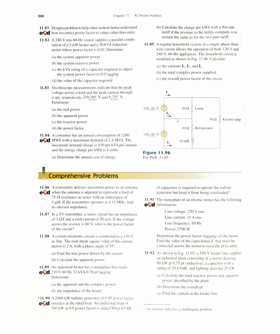
11.85 A regular household system of a single-phase three- wire circuit allows the operation of both 120-V and 240-V, 60-Hz appliances. The household circuit is modeled as shown in Fig. 11.96. Calculate:
(a) the currents I ,. I2, and I„
(b) the total complex power supplied
(c) the overall power factor of the circuit
120/ ( T V ( t ) 10 £2 f Lamp
120 / 0 ° V ( ? )
Figure 11.96For Prob. 11 .85.
3 0 12 > Kitchen ramp
Comprehensive Problems11.86 A transmitter delivers maximum power to an antenna e€d when the antenna is adjusted to represent a load of
7 5 -0 resistance in series with an inductance of 4 /uH. If the transmitter operates at 4.12 MHz, find its internal impedance.
11.87 In a TV transmitter, a series circuit has an impedance of 3 kO and a total current of 50 mA. If the voltage across the resistor is 80 V, what is the pow er factor of the circuit?
11.88 A certain electronic circuit is connected to a 110-V ac line. The root-mean-square value of the current drawn is 2 A, with a phase angle of 55°.
(a) Find the true power drawn by the circuit.
(b) Calculate the apparent power.
11.89 An industrial heater has a nameplate that reads: e € d 2 10 V 60 Hz 12 kVA 0.78 pf lagging
Determine:
(a) the apparent and the complex power
(b) the impedance of the heater
* 11.90 A 2000-kW turbine-generator of 0.85 power factor operates at the rated load. An additional load of 300 kW at 0.8 power factor is added.W hat kVAR
of capacitors is required to operate the turbine- generator but keep it from being overloaded1
11.91 The nameplate of an electric motor has the following e O d information:
Line voltage: 220 V rms
Line current: 15 A rm s
Line frequency: 60 Hz Power: 2700 W
Determine the power factor (lagging) of the motor. Find the value of the capacitance C that must be connected across the motor to raise the pf to unit)
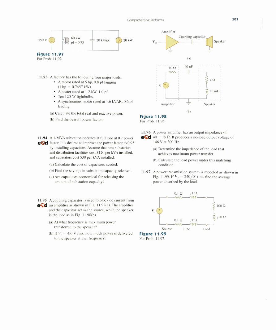
11.92 As shown in Fig. 11.97, a 550-V feeder line supplies an industrial plant consisting of a motor drawing 60 kW at 0.75 pf (inductive), a capacitor with a rating of 20 kVAR, and lighting drawing 20 k ^
(a) Calculate the total reactive power and apparent pow er absorbed by the plant.
(b) Determine the overall pf.
(ci Find the current in the feeder line.
An asterisk indicates a challenging problem
Comprehensive Problems 501
Amplifier
550 V ( i ) =|= 20kVAR ( ■ 20 kW
Figure 11.97For Prob. 11.92.
Coupling capacitor
(a)
Speaker
11.93 A factory has the following four major loads:• A motor rated at 5 hp, 0.8 pf lagging
(I hp = 0.7457 kW).• A heater rated at 1.2 kW, 1.0 pf.• Ten 120-W lightbulbs.• A synchronous motor rated at 1.6 kVAR, 0.6 pf
leading.
(a) Calculate the total real and reactive power.
(b) Find the overall power factor.Figure 11.98For Prob. 11 .95.
(b)
11.94 A 1-MVA substation operates at full load at 0.7 power e€d factor. It is desired to improve the power factor to 0.95
by installing capacitors. Assume that new substation and distribution facilities cost $120 per kVA installed, and capacitors cost $30 per kVA installed.
(a) Calculate the cost of capacitors needed.
(b) Find the savings in substation capacity released.
(c) Are capacitors economical for releasing the amount of substation capacity?
11.96 A power amplifier has an output impedance of eOd 40 + j 8 fl. It produces a no-load output voltage of
146 V at 300 Hz.
(a) Determine the impedance of the load that achieves maximum power transfer.
(b) Calculate the load power under this matching condition.
11.97 A power transmission system is modeled as shown in Fig. 11.99 If V,. = 240/0 ° rms. find the average power absorbed by the load.
11.95 A coupling capacitor is used to block dc current from e€ti an amplifier as shown in Fig. 11.98(a). The amplifier
and the capacitor act as the source, while the speaker is the load as in Fig. 11 98(b).
(a) At what frequency is maximum power transferred to the speaker?
(b) If Vx = 4.6 V rms, how much power is delivered to the speaker at that frequency ?
0.1 Q j I £2
Figure 1 1 .9 9For Prob. 11.97.

Three-Phase CircuitsHe who cannot forgive others breaks the bridge over which he must pass himself
— G. Herbert
Enhancing Your Skills and Your CareerABET EC 2000 criteria (3.e), "an a b i l i t y t o id e n t i f y , fo rm u la te , a n d s o l v e e n g in e e r in g p r o b l e m s . "Developing and enhancing your “ability to identify, formulate, and solve engineering problems" is a primary focus of textbook. Following our six step problem-solving process is the best way to practice this skill. Our recommendation is that you use this process whenever possible. You may be pleased to learn that this process works well for
ABET EC 2000 criteria (f), "an u n d e r s ta n d in g o f p r o f e s s io n a l a n d e th i c a l r e s p o n s i b i l i t y . "“An understanding of professional and ethical responsibility” is required of every engineer. To some extent, this understanding is very personal for each of us. Let us identify some pointers to help you develop this understanding. One of my favorite examples is that an engineer has the responsibility to answer what I call the “unasked question.” For instance, assume that you own a car that has a problem with the transmission. In the process of selling that car, the prospective buyer asks you if there is a problem in the right-front wheel bearing. You answer no. However, as an engineer, you are required to inform the buyer that there is a problem with the transmission without being asked.
Your responsibility both professionally and ethically is to perform in a manner that does not harm those around you and to whom you are responsible. Clearly, developing this capability will take time and maturity on your part. I recommend practicing this by looking for professional and ethical components in your day-to-day activities.
Photo by Charles Alexander
503
504 Chapter 12 Three-Phase Circuits
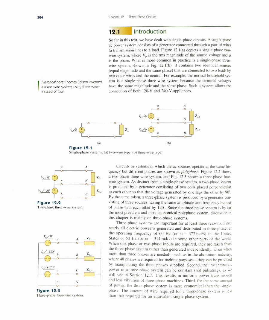
12.1 IntroductionSo far in this text, we have dealt with single-phase circuits. A single-phase ac power system consists of a generator connected through a pair of wires (a transmission line) to a load. Figure 12.1(a) depicts a single-phase two- wire system, where Vp is the rms magnitude of the source voltage and <f> is the phase. What is more common in practice is a single-phase three- wire system, shown in Fig. 12.1(b). It contains two identical sources (equal magnitude and the same phase) that are connected to two loads by two outer wires and the neutral. For example, the normal household sys-
I Historical note- Thomas Edison invented tem *s a single-phase three-wire system because the terminal \oltages a three-wire system, usins three wires have the same magnitude and the same phase. Such a system allows the instead of four. connection of both 120-V and 240-V appliances.
a A
(a) (b)Figure 12.1Single-phase systems: (a) two-wire type, (b) three-wire type.
K / t ( t
a-O-
K/-90°
n- o -
V 2!
b - 0 -
A-o-
H-o-
Vn/+ \2 0 °
— Q — o~
A-O-
N- O C
B-o-
Figure 12.2Two-phase three-wire system.
C Z /.3 -O----1
Figure 1 2 .3Three-phase four-wire system.
Circuits or systems in which the ac sources operate at the same frequency but different phases are known as polyphase. Figure 12.2 shows a two-phase three-wire system, and Fig. 12.3 shows a three-phase four- wire system. As distinct from a single-phase system, a two-phase system is produced by a generator consisting of two coils placed perpendicular to each other so that the voltage generated by one lags the other by 90°. By the same token, a three-phase system is produced by a generator consisting of three sources having the same amplitude and frequency but out of phase with each other by 120°. Since the three-phase system is by far the most prevalent and most economical polyphase system, discassion in this chapter is mainly on three-phase systems.
Three-phase systems are important for at least three reasons. First, nearly all electric power is generated and distributed in three-phase, at the operating frequency of 60 Hz (or a» = 377 rad/s) in the United States or 50 Hz (or m = 314 rad/s) in some other parts of the world. When one-phase or two-phase inputs are required, they are taken from the three-phase system rather than generated independently. E\en when more than three phases are needed— such as in the aluminum industry where 48 phases are required for melting purposes—they can be provided by manipulating the three phases supplied. Second, the instantaneous power in a three-phase system can be constant (not pulsating i. as we will see in Section 12.7. This results in uniform power transmission and less vibration of three-phase machines. Third, for the same amount ot power, the three-phase system is more economical than the single- phase. The amount of wire required for a three-phase system is less than that required for an equivalent single-phase system.

12.2 Balanced Three-Phase Voltages 505
HistoricalNikola Tesla (1856-1943) was a Croatian-American engineer whose inventions— among them the induction motor and the first polyphase ac power system—greatly influenced the settlement of the ac versus dc debate in favor of ac. He was also responsible for the adoption of 60 Hz as the standard for ac power systems in the United States.
Bom in Austria-Hungary (now Croatia), to a clergyman, Tesla had an incredible memory and a keen affinity for mathematics. He moved to the United States in 1884 and first worked for Thomas Edison. At that time, the country was in the “battle of the currents” with George Westinghouse (1846-1914) promoting ac and Thomas Edison rigidly leading the dc forces. Tesla left Edison and joined Westinghouse because of his interest in ac. Through Westinghouse, Tesla gained the reputation and acceptance of his polyphase ac generation, transmission, and distribution system. He held 700 patents in his lifetime. His other inventions include high-voltage apparatus (the tesla coil) and a wireless transmission system. The unit of magnetic flux density, the tesla, was named in honor of him.
We begin with a discussion of balanced three-phase voltages. Then we analyze each of the four possible configurations of balanced three- phase systems. We also discuss the analysis of unbalanced three-phase systems. We learn how to use PSpice fo r Windows to analyze a balanced or unbalanced three-phase system. Finally, we apply the concepts developed in this chapter to three-phase power measurement and residential electrical wiring.
12.2 Balanced Three-Phase VoltagesThree-phase voltages are often produced with a three-phase ac generator (or alternator) whose cross-sectional view is shown in Fig. 12.4. The generator basically consists of a rotating magnet (called the rotor) surrounded by a stationary- winding (called the stator). Three separate
Figure 12 .4A three-phase generator.
Courtesy Smithsonian Institution
506 Chapter 12 Three-Phase Circuits
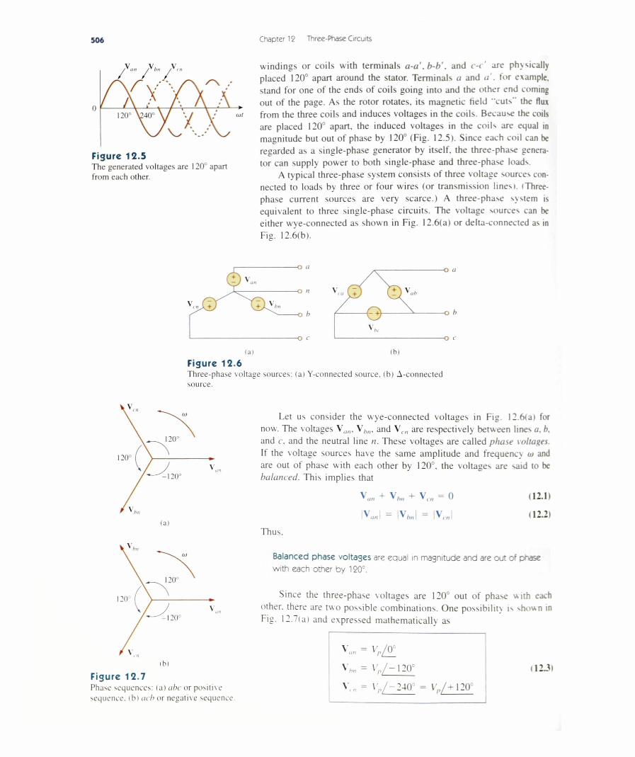
Figure 12.5The generated voltages are 120° apart from each other.
windings or coils with terminals a-a , b-b'. and c-c' are physically placed 120° apart around the stator. Terminals a and a', tor example, stand for one of the ends of coils going into and the other end coming out of the page. As the rotor rotates, its magnetic field "cuts'' the flux from the three coils and induces voltages in the coils Because the coils are placed 120° apart, the induced voltages in the coils are equal in magnitude but out of phase by 120° (Fig. 12.5). Since each coil can be regarded as a single-phase generator by itself, the three-phase generator can supply power to both single-phase and three-phase loads.
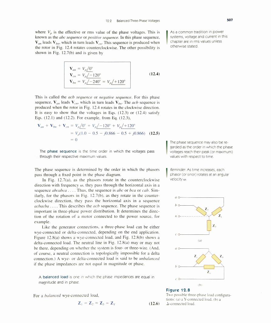
A typical three-phase system consists of three voltage sources connected to loads by three or four wires (or transmission lines). (Three- phase current sources are very scarce.) A three-phase system is equivalent to three single-phase circuits. The voltage sources can be either wye-connected as shown in Fig. 12.6(a) or delta-connected as in Fig. 12.6(b).
Figure 12.6Three-phase voltage sources: (a) Y-connected source, (b) A-connected source.
Let us consider the wye-connected voltages in Fig. 12.6(a) for now. The voltages Vu„, V/,,,, and \ cn are respectively between lines a. b. and c, and the neutral line n. These voltages are called phase voltages. If the voltage sources have the same amplitude and frequency w and
v „ are out of phase with each other by 120°, the voltages are said to bebalanced. This implies that
v u„ + V„„ + V,„ = 0 (12.1)
(b)Figure 12.7Phase sequences: (a) abc or positive sequence, (b) acb or negative sequence
Thus.
Balanced phase voltases are equal in magnitude and are out of phase with each other by 120°.
Since the three-phase voltages are 120° out of phase with each other, there are two possible combinations. One possibility is shown in Fig. 12.7(a) and expressed mathematically as
V„» = Vp/ ( f
v„„ = Vp/ — 120°
v,„ = \ ; / - 2 4 0 ° = vy,/ + 120
(12J)
12 2 Balanced Three-Phase Voltages 507
where Vp is the effective or rms value of the phase voltages. This is known as the abc sequence or positive sequence. In this phase sequence, \ an leads Vhn, which in turn leads Vc„. This sequence is produced when the rotor in Fig. 12.4 rotates counterclockwise. The other possibility is shown in Fig. 12.7(b) and is given by
As a common tradition in power systems, voltage and current in this chapter are in rms values unless otherwise stated.
Va„ = vp/ v
Vcn = Vp/ — 120°
V hn = Vp/-2 A 0 ° = Vp/+ 120°
(12.4)
This is called the acb sequence or negative sequence. For this phase sequence, Va„ leads Vcn, which in turn leads \ bn. The acb sequence is produced when the rotor in Fig. 12.4 rotates in the clockwise direction. It is easy to show that the voltages in Eqs. (12.3) or (12.4) satisfy Eqs. (12.1) and (12.2). For example, from Eq. (12.3),
Vp/ 0° + Vp/ —120° + Vp/ + 120°Vp( 1.0 - 0.5 - y0.866 - 0.5 + ;0.866) (12.5)
0
V,„, + V,„ + V
The phase sequence is the time order in which the voltages pass through their respective maximum values.
The phase sequence may also be regarded as the order in which the phase voltages reach their peak (or maximum) values with respect to time.
The phase sequence is determined by the order in which the phasors pass through a fixed point in the phase diagram.
In Fig. 12.7(a), as the phasors rotate in the counterclockwise direction with frequency a>, they pass through the horizontal axis in a sequence abcabca . . . . Thus, the sequence is abc or bca or cab. Similarly, for the phasors in Fig. 12.7(b), as they rotate in the counterclockwise direction, they pass the horizontal axis in a sequence acbacba . . . . This describes the acb sequence. The phase sequence is important in three-phase power distribution. It determines the direction of the rotation of a motor connected to the power source, for example.
Like the generator connections, a three-phase load can be either wye-connected or delta-connected, depending on the end application. Figure 12.8(a) shows a wye-connected load, and Fig. 12.8(b) shows a delta-connected load. The neutral line in Fig. 12.8(a) may or may not be there, depending on whether the system is four- or three-wire. (And. of course, a neutral connection is topologically impossible for a delta connection.) A wye- or delta-connected load is said to be unbalanced if the phase impedances are not equal in magnitude or phase.
A balanced load is one in which the phase impedances are equal in magnitude and in phase.
For a balanced wye-connected load,
Reminder. As time increases, each phasor (or sinor) rotates at an angular velocity w
lal
Z, = Z: = Z, = Zy (12.6)
(biFigure 12.8Two possible three-phase load configurations: (a) a Y-connected load, (b) a A-connected load.
510 Chapter 12 Three-Phase Circuits
(b)
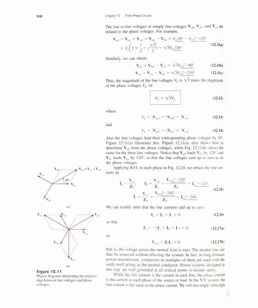
Figure 12.11Phaser diagrams illustrating the relation ship between line voltages and phase voltages.
The line-to-line voltages or simply line voltages \ ah. VN. and Vta are related to the phase voltages. For example,
v u„ = v u„ + V,,, - Vun - \ hn = Vp/W - Vr/ - \ 2 ( V( I V 3 / - . „ ( 12.11a)
= V ^ l + z + j — ) = V 3V ./30°
Similarly, we can obtain
V * - V„„ - V,„ = V3V„/ - 9 0 ° 112.11b)
Vru = V,„ - V„„ = V3V„/ - 2 1 0 ° (12.11c)
Thus, the magnitude of the line voltages V, is V 3 times the magnitude of the phase voltages Vp. or
( 12.12)
wherev „ = I V J = |V J = |V,.„| (12.13)
and VL = |V J = IV ,,| = |V,.J (12.14)
Also the line voltages lead their corresponding phase voltages by 30°. Figure 12.11(a) illustrates this. Figure 12.11(a) also shows how to determine \ ah from the phase voltages, while Fig. 12.11(b) shows the same for the three line voltages. Notice that \ ah leads V^. b> 120'. and \ hc leads Vra by 120°, so that the line voltages sum up to zero as do the phase voltages.
Applying KVL to each phase in Fig. 12.10, we obtain the line currents as
V V, V ,,,,/— 120°I = — I - — - L - I /-i"> n
Zy' h ~ Z y ~ Zy
v V „„/-240°
Z>> Ly
(12.15)
We can readily infer that the line currents add up to zero.
Iu + 1„ + I( . = 0 (12.161
so that
I». = + I/. + Ir) “ 0 (12.17a)
or
Vn„ = Z,,I(1 = 0 (12.17b)
that is. the voltage across the neutral wire is zero. The neutral line can thus be removed w ithout affecting the system. In fact, in long distance power transmission, conductors in multiples of three are used with the earth itself acting as the neutral conductor. Power systems designed in this wa\ are well grounded at all critical points to ensure safety
While the line current is the current in each line, the phase current is the current in each phase of the source or load. In the Y-Y system. the line current is the same as the phase current. We will use single subscripts