Embed Size (px)
Citation preview

FUNDAMENTALS of EEG TECHNOLOGY
All you need to know about electricity and electronics as they
relate to EEGMr. John R. Ives, B.Sc.
University of Western OntarioLondon, Ontario, Canada

LEARNING OBJECTIVES
•Basic and applied physics as they relate to EEG
•Practical issues related to the acquisition of EEG
•Basic features of digital EEG

Disclosures: Conflict of Interest
•Ives EEG Solutions, Inc•Patent: Ambulatory EEG:
DigiTrace/SleepMed•Patent: fMRI/EEG:
NeuroScan/Compumedics•Stellate, Ad-Tech, MVAP, Grass•Jordan Neuroscience

Source of the EEG• Neurons
– post synaptic junction of the pyramidal cell• Cerebral cortex
– 2mm thick by 1.6 m2 (16,000 cm2 or 17.2 sq ft)• Spike in the EEG
– at least 6 cm2 of synchronous cortex (0.04%)• Problem
– human cortex is a super origami figure surrounded by bone and skin
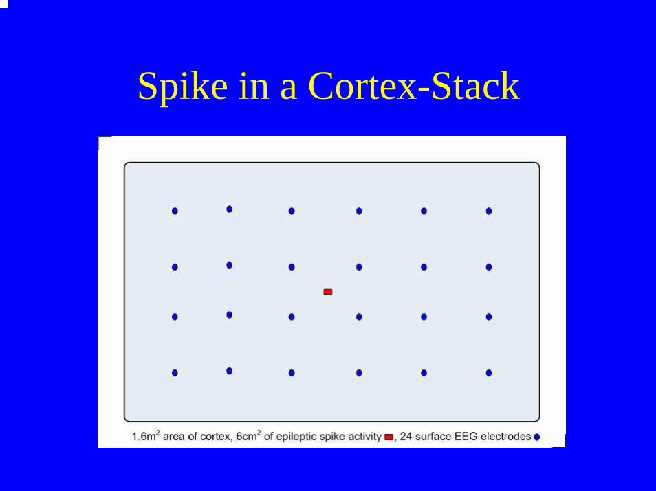
Spike in a Cortex-Stack

References• Elul, R. The Genesis of the EEG. International Review of Neurobiology, 15:227-
272 (1972).• Speckmann, E-J. and Elger, C.E. Neurophysiological Basis of the EEG and of
DC Potentials. In: E. Niedermeyer and F. Lopes daSilva, eds. Electroencephalography: Basic Principles, Clinical Applications and Related Fields. Urban and Schwarzenberg, Baltimore-Munich, pp. 1-13 (1982).
• Lopes daSilva, F. and Van Rotterdam, A. Biophysical Aspects of EEG and MEG Generation. In: E. Niedermeyer and F. Lopes daSilva, eds. Electroencephalography: Basic Principles, Clinical Applications and Related Fields. Urban and Schwarzenberg, Baltimore-Munich, pp. 15-26 (1982).
• Gloor, P. Neuronal Generators and the Problem of Localization inElectroencephalography: Application of Volume Conductor Theory to Electroencephalography. Journal of Clinical Neurophysiology, 2(4):327-354 (1985).
• Plonsey, R. Volume-conductor Fields. Chapter 5 in Bioelectric Phenomena. McGraw Hill, New York, pp. 202-275 (1969).
• Tyner, F., Knott, J., and Mayer, W. Fundamentals of EEG Technology. Lippincott Williams & Wilkins, 1983
• Ebersole, J. Defining epileptogenic foci: past, present, future. J. of Clin. Neurophysio., 14(6), 470-483, 1997.
• http:www.ccs.fau.edu/~bressler/EDU/NSP/Modules/IV.pdf

Pyramidal Neurons
• Perpendicular to cortex • Elongated neurons• Parallel with apical dendrites

Electromagnetic Field
• EEG measure electrical potential
• MEG measures magnetic activity
• EEG and MEG 90 degrees• EEG “sees” gyri activity• MEG “sees” sulcus activity
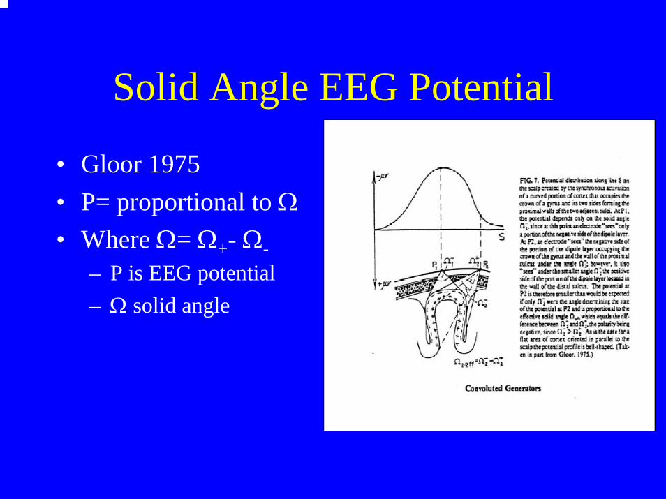
Solid Angle EEG Potential
• Gloor 1975• P= proportional to Ω• Where Ω= Ω+- Ω-
– P is EEG potential– Ω solid angle

How to Record EEG
• Transducer: electrode• Amplifier: increase signal amplitude• Display: was paper now CPU screen• Storage: was paper now digital media• # of channels: 2, 4, 8, 16, 24, 32, 64, 128, 256
surface invasive• Montage: sequenced bipolar, now referential
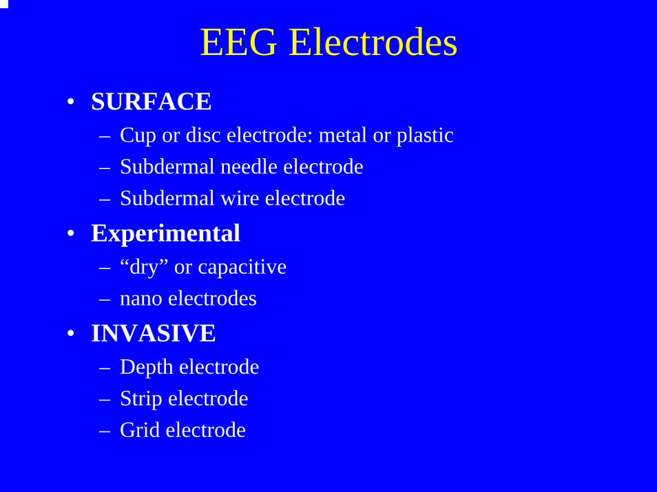
EEG Electrodes• SURFACE
– Cup or disc electrode: metal or plastic– Subdermal needle electrode– Subdermal wire electrode
• Experimental– “dry” or capacitive– nano electrodes
• INVASIVE– Depth electrode– Strip electrode– Grid electrode

EEG Electrodes: Ideal• Low Resistance
– large surface area– rough surface
• Low DC Offset– Silver-Silver/Chloride (Ag-Ag/Cl)– Similar material, do not mix electrode types– Pure silver, no contaminants
• Imaging Compatible– convenient; particularly, in the ICU during cEEG
• Ideal is pure silver with a Ag-Ag/Cl coat– Ok for scalp and subdermal– not OK for invasive neuronal contact, best with SS, Au, Pt

EEG Electrodes

Some Basic: Resistor
• Resistor, R, ohm, Ω• Voltage drops across a resistor• Resistance: DC current• Impedance: AC current
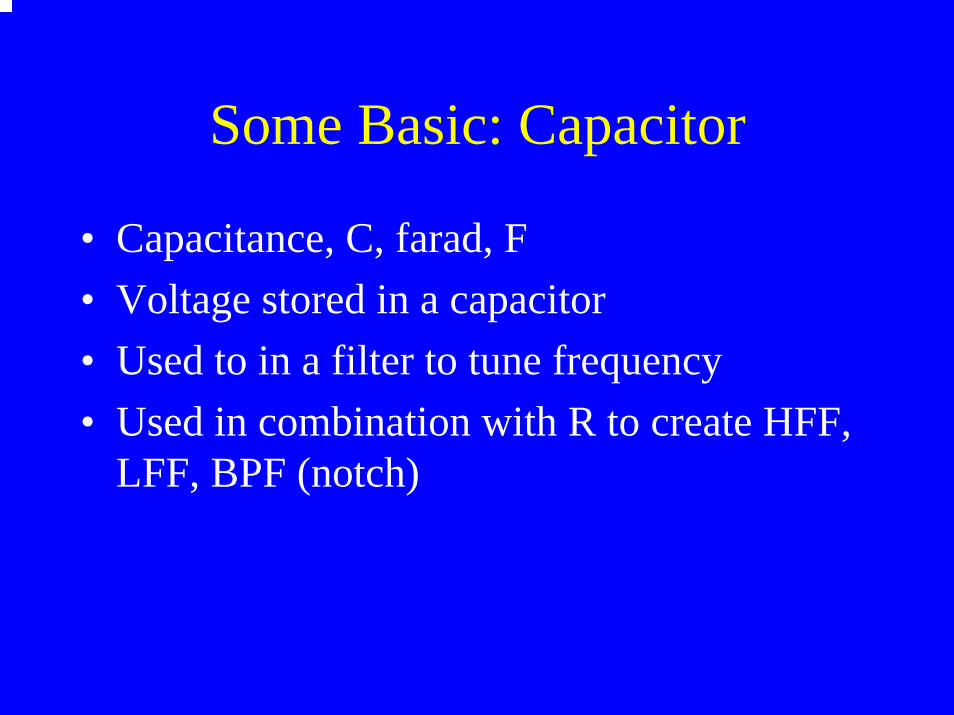
Some Basic: Capacitor
• Capacitance, C, farad, F• Voltage stored in a capacitor• Used to in a filter to tune frequency• Used in combination with R to create HFF,
LFF, BPF (notch)

Preamp vs Amp
• Amplifier is usually designed in stages• Preamp, front-end, high impedance, buffer,
usually low gain, LFF, decoupling• Amp, high gain, HFF• Using modern operational amplifiers, all
functionality can be achieved with a single stage
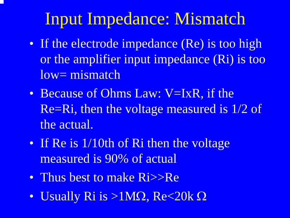
Input Impedance: Mismatch• If the electrode impedance (Re) is too high
or the amplifier input impedance (Ri) is too low= mismatch
• Because of Ohms Law: V=IxR, if the Re=Ri, then the voltage measured is 1/2 of the actual.
• If Re is 1/10th of Ri then the voltage measured is 90% of actual
• Thus best to make Ri>>Re• Usually Ri is >1MΩ, Re<20k Ω

Ground and Leakage Current
• Best to ground the patient at one point• If not possible, make sure that leakage
current is low (<3µA)• Leakage current is generated by long AC
cable and power supply• Best to have current limiting in all patient
leads (std in modern EEG)

Impedance Simplified
EEG Characteristics
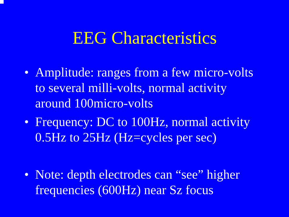
• Amplitude: ranges from a few micro-volts to several milli-volts, normal activity around 100micro-volts
• Frequency: DC to 100Hz, normal activity 0.5Hz to 25Hz (Hz=cycles per sec)
• Note: depth electrodes can “see” higher frequencies (600Hz) near Sz focus

EEG Machine (analog): paper/ink
From: Tyner et al.From: Tyner et al.

Digital: not much analog left• Input box• Amplifier• A/D converter• everything else is software
– montage– gain– high frequency filter (HFF)– low frequency filter (LFF)– notch filter (BPF)
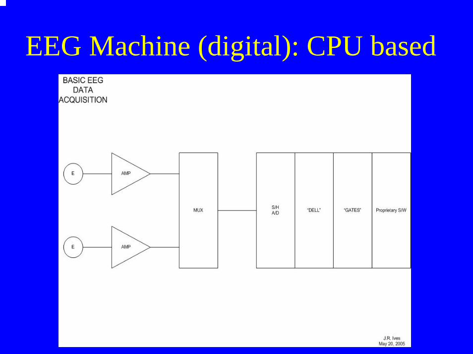
EEG Machine (digital): CPU based

Digital Front-End
• Low-frequency filter (LFF), decoupling• High-frequency filter (HFF), anti-aliasing• Wide-band, open filter• All selective filtering performed by software• Referential based amplifiers• remontaging performed by software• Sample/hold, A/D converter

Sensitivity & Gain
• Sensitivity is microvolts (µ) of input to produce 1mm of “pen” deflection (CPU screen), 1µV/mm, 10µV/mm, 100 µV/mm
• Gain is the amplification factor of the preamp. A gain of 1,000 means that an EEG signal of 10µV becomes 10mV

Analog Front-End Filter
• F=1/2πRC, where RC is the time constant (TC)• Resistor and Capacitor define 3db down point• Wide-band recording• Low frequency is usually 0.5Hz• High frequency is usually 100Hz• Digital sample rate >200Samples/Sec/Chan

Filter Characteristics• Filters attenuate they do not eliminate• Filters will attenuate high frequencies, but may
reveal low frequency components within• Filters attenuate spikes, but will not eliminate
them, just changes the degree of “sharpness”• Filters should be used selectively not generally• Filters will not generate frequencies, unless
there is aliasing• Aliasing is the fold back of frequencies

High Frequency Filtering

HFF Example

Effects of HFF and LFF on DC Pulse
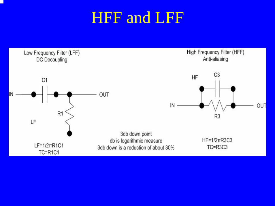
HFF and LFF

Diff/Ref EEG Amplifier

Real Differential EEG Amplifier

A/D Converter• At least 2x (best 5x) any frequency of interest• >200S/S/Chan, surface• >700S/S/Chan, invasive• bit resolution: amplitude • 8bit 256 levels 1µV to 256µV range• 12bit 4,096 levels 1µV to 4mV • 16bit 65,536 levels 1µV to 0.65V

EEG Clinical Applications
• Clinical• Prolonged (or Day LTM)• LTM in the EMU
– LTM with invasive electrodes• Ambulatory LTM• cEEG in the NICU• EEG in the ED

cEEG in the NeuroICU
• Same as LTM in the EMU• BUT
– the NICU is not under the control of EEG– EEG conflicts with imaging– lots of external artifact– EEG not the priority– on/off of electrodes for imaging

Skin Prep, Electrode Glue, GelsSurface Electrodes
• Skin is a good insulator and must be prepared to allow some conduction
• Electrodes need to be fixed to the head with a paste or glue such as collodion
• Conductive gel needs to “wet” the scalp and electrode
• Electrode impedance is always deteriorating
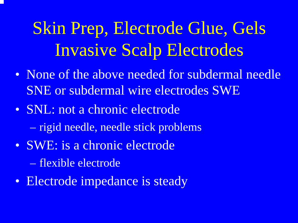
Skin Prep, Electrode Glue, GelsInvasive Scalp Electrodes
• None of the above needed for subdermal needle SNE or subdermal wire electrodes SWE
• SNL: not a chronic electrode– rigid needle, needle stick problems
• SWE: is a chronic electrode– flexible electrode
• Electrode impedance is steady


Subdermal Wire Electrode (SWE): 0.25x3mm Ag-Ag/Cl tip

SWE: 3-Stages of Insertion
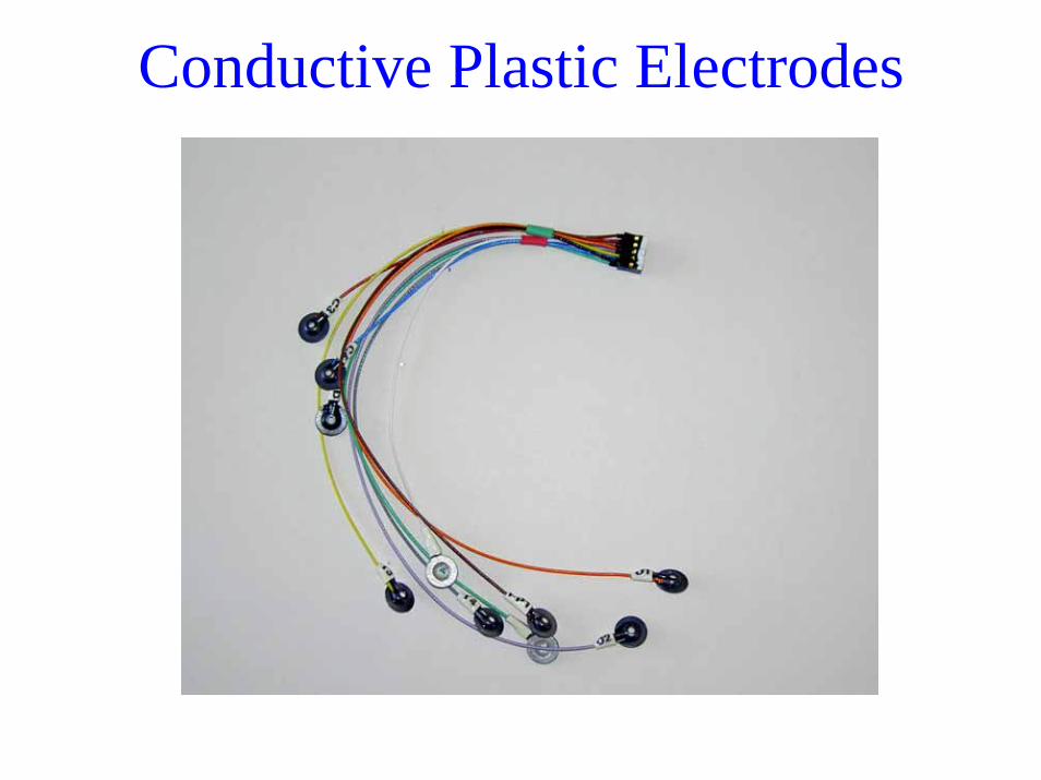
Conductive Plastic Electrodes
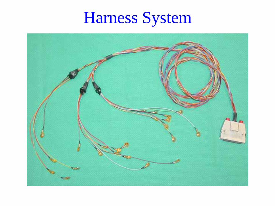
Harness System

Electrodes Ready for Imaging