Embed Size (px)
DESCRIPTION
fund
Citation preview
METALLURGY TRAINING MODULE 4 REV. A01
BY
JDD
DATE
11/24/12 Fundamentals of Corrosion
Page 1 of 46 APPROVED
DATE
Introduction
Corrosion is the degradation of a metal due to chemical or electrochemical interaction with its environment. It may or may not involve actual loss of material. In the Oil Patch we deal with some of the most hostile environments in the world. It is vital that the engineers who design and specify materials for ARGUS Subsea equipment have a good understanding of the fundamentals of corrosion. Corrosion can shorten the lifetime of our equipment. It may interfere with the functioning of the equipment. It may be very slow and insidious, or sudden and catastrophic. Once equipment is installed, it’s too late: corrosion must be accounted for in the design stages. There are many mechanisms for corrosion. It is important that you become familiar with each in order to be able to mitigate or prevent their occurrence through proper design and material selection. In this training module we’ll introduce the basics of corrosion. We’ll build upon this in the next module by examining wellhead and trim selection.
The Chemistry of Corrosion
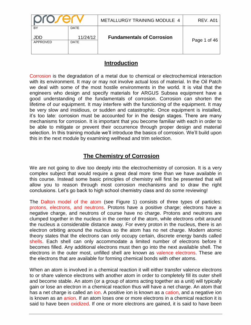
We are not going to dive too deeply into the electrochemistry of corrosion. It is a very complex subject that would require a great deal more time than we have available in this course. Instead some basic principles of chemistry will first be presented that will allow you to reason through most corrosion mechanisms and to draw the right conclusions. Let’s go back to high school chemistry class and do some reviewing! The Dalton model of the atom (see Figure 1) consists of three types of particles: protons, electrons, and neutrons. Protons have a positive charge; electrons have a negative charge, and neutrons of course have no charge. Protons and neutrons are clumped together in the nucleus in the center of the atom, while electrons orbit around the nucleus a considerable distance away. For every proton in the nucleus, there is an electron orbiting around the nucleus so the atom has no net charge. Modern atomic theory states that the electrons can only occupy certain, discrete energy bands called shells. Each shell can only accommodate a limited number of electrons before it becomes filled. Any additional electrons must then go into the next available shell. The electrons in the outer most, unfilled shell are known as valence electrons. These are the electrons that are available for forming chemical bonds with other atoms. When an atom is involved in a chemical reaction it will either transfer valence electrons to or share valence electrons with another atom in order to completely fill its outer shell and become stable. An atom (or a group of atoms acting together as a unit) will typically gain or lose an electron in a chemical reaction thus will have a net charge. An atom that has a net charge is called an ion. A positive ion is known as a cation, and a negative ion is known as an anion. If an atom loses one or more electrons in a chemical reaction it is said to have been oxidized. If one or more electrons are gained, it is said to have been
METALLURGY TRAINING MODULE 4 REV. A01
BY
JDD
DATE
11/24/12 Fundamentals of Corrosion
Page 2 of 46 APPROVED
DATE
reduced. An easy way to remember the difference is the Spanish word Ole! (Oxidation Loses Electrons). Note that oxidation may or may not involve oxygen.
Figure 1: The Dalton Model of the Atom
Now we are going to shift gears and talk about a French chemist named Henry Louise Le Chatelier (1850-1936). Le Chatelier studied chemical equilibrium and developed a fundamental principle that describes how a system in equilibrium reacts to an external stimulus. Le Chatelier’s principle states that a system in chemical equilibrium always acts to oppose changes in equilibrium. To restore equilibrium; the system will favor a chemical reaction to reduce or eliminate the disturbance in order to restabilize at thermodynamic equilibrium. In other words, if a system in equilibrium is subjected to a change in concentration, temperature, or total pressure, the equilibrium will shift in order to minimize that change. A good grasp of Le Chatelier’s principle will stand you in good stead when it comes to working through some of the corrosion processes that we’ll be talking about without having to tread the dangerous waters of thermodynamics, electrochemistry, or the Nernst equation! Let’s start out be defining what we mean by equilibrium. We’ll use a hypothetical example of a solution of A and B reacting to form C and D. When we first pour the solution of A into a beaker with a solution of B in it, the A will immediately start to react with B to form C and D. The amount of A and B will decrease as the amount of C and D increases, but only until a certain concentration of C and D is reached. At this point, the
METALLURGY TRAINING MODULE 4 REV. A01
BY
JDD
DATE
11/24/12 Fundamentals of Corrosion
Page 3 of 46 APPROVED
DATE
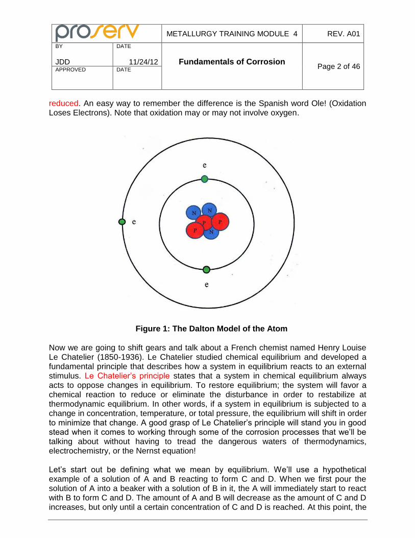
equilibrium point, some of the C and D dissociate to A and B at the same rate that A and B are reacting to form C and D. At equilibrium, the amounts of reactants and products remain the same. Note that there are still lots of reactions occurring, but there is no net gain or loss of the reactants or products. In chemical shorthand we can write our chemical equation at equilibrium as A + B ↔ C + D. We’ll use Le Chatelier’s principle to find out what happens to the equilibrium point in the reaction A + B ↔ C + D when we change the concentration of one of the substances. I call Le Chatelier’s principle the teeter totter principle (or see saw principle depending on what part of the country you’re from) for reasons that will become self evident. Figure 2 illustrates our hypothetical chemical reaction in equilibrium.
+ ↔ +
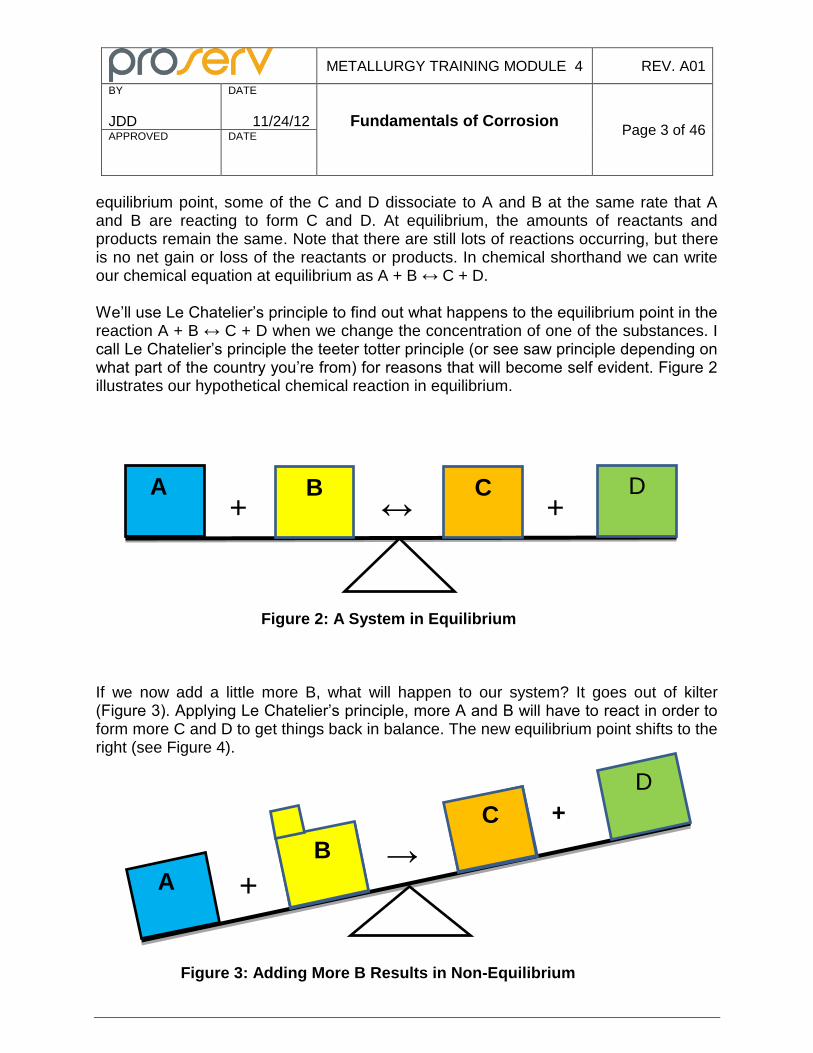
Figure 2: A System in Equilibrium If we now add a little more B, what will happen to our system? It goes out of kilter (Figure 3). Applying Le Chatelier’s principle, more A and B will have to react in order to form more C and D to get things back in balance. The new equilibrium point shifts to the right (see Figure 4).
Figure 3: Adding More B Results in Non-Equilibrium
A B D C
A
B
D
C
B
C
+ →
+
METALLURGY TRAINING MODULE 4 REV. A01
BY
JDD
DATE
11/24/12 Fundamentals of Corrosion
Page 4 of 46 APPROVED
DATE
+ ↔ +
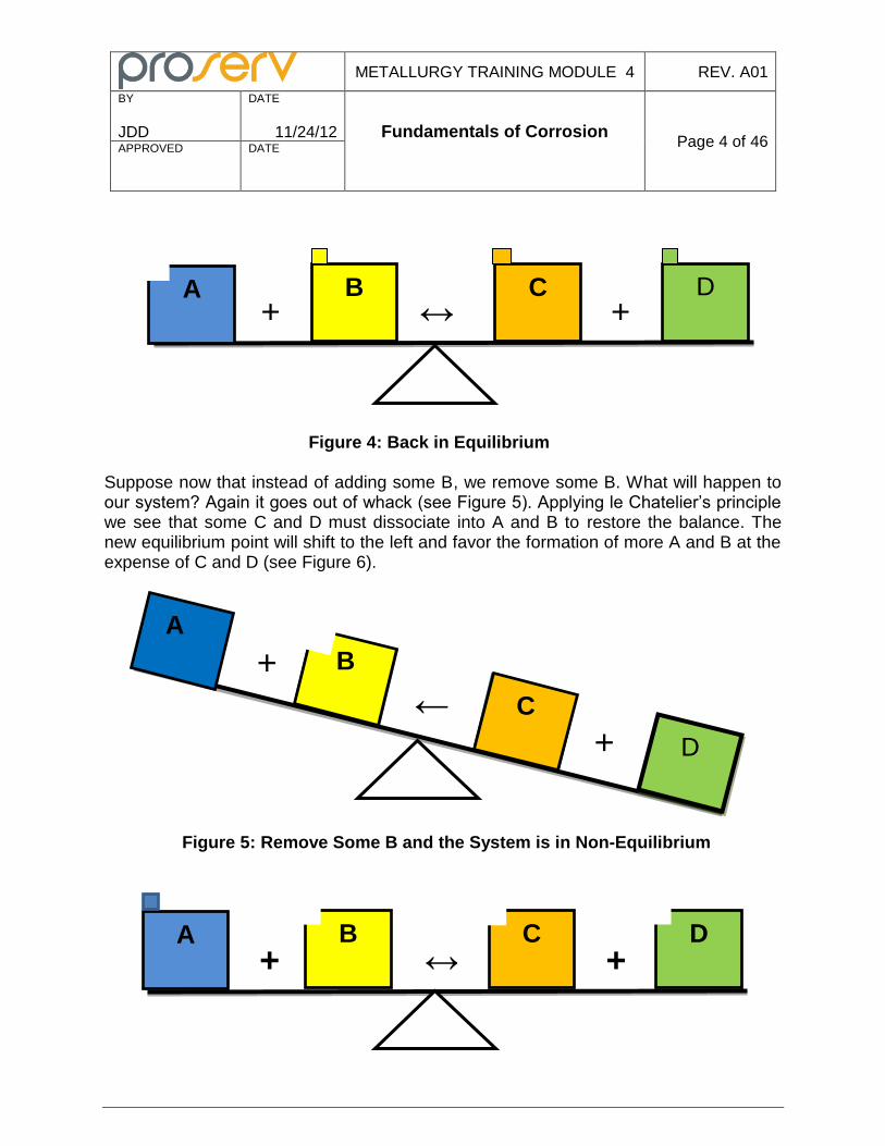
Figure 4: Back in Equilibrium Suppose now that instead of adding some B, we remove some B. What will happen to our system? Again it goes out of whack (see Figure 5). Applying le Chatelier’s principle we see that some C and D must dissociate into A and B to restore the balance. The new equilibrium point will shift to the left and favor the formation of more A and B at the expense of C and D (see Figure 6).
Figure 5: Remove Some B and the System is in Non-Equilibrium
A B D C
B
C
+
←
← +
A
D
B
C
C A B D + ↔ +
METALLURGY TRAINING MODULE 4 REV. A01
BY
JDD
DATE
11/24/12 Fundamentals of Corrosion
Page 5 of 46 APPROVED
DATE
Figure 6: Back in Equilibrium From our time well spent on the playground with the teeter totters, we can see that if we add reactants to one side of a chemical reaction in equilibrium, the equilibrium point will shift in favor of the formation of additional products on the other side. If we remove some products from one side of a chemical reaction in equilibrium, more of the products on the other side will react to make up the loss and establish a new equilibrium point. So much for Le Chatelier and his teeter totters. Now we need to discuss water – the liquid phase of H2O. There can be no corrosion of our equipment unless there is water present. An understanding of the chemistry water is essential to understanding Oil Patch corrosion. If we look at a glass full of water there doesn’t appear to be much going on, but looks can be deceiving! At any given moment of time there are water molecules dissociating into H
+ (hydrogen) and OH
- (hydroxyl) ions; and an equal
number of both H+ and OH
- ions recombining to form water molecules. We can show
this using chemical shorthand as:
H2OLiquid ↔ H+ + OH- The amount of H+ ions in solution at room temperature is approximately 10
-7 mole/liter
of water. A “mole” as you may recall from your high school chemistry class is the number of atoms in 12 grams of carbon 12 which is equal to Avagadro’s number of 6.023 X 10
23.
The amount of H+ ions although relatively small in comparison to the amount of water molecules present in our glass of water, plays a very important role in the corrosion of metals. It gets rather awkward talking about the concentration of H
+ ions in terms of 10
to some negative exponent so we’ll refer to the concentration in terms of pH. The pH of an aqueous solution is defined as follows:
pH = log 1/ [H+] = - log [H+]
Where [H+] is the concentration of the H+ in moles/liter.
The pH of the water in our glass at room temperature will be – log [10
-7] which equals 7.
By definition, a solution with a pH of 7 is said to be neutral. Note from our formula that the more H
+ ions we have, the lower the value of pH will be. A solution with a pH below
7 (thus with more H+ ions than water at room temperature) is by definition an acid
solution. A solution with a pH over 7 (thus with fewer H+ ions than water at room
temperature) is by definition a base (or alkaline) solution. If we immerse a carbon steel part into water it will corrode. We can summarize the overall reaction as:
4Fe + 3O2 + 6H2O → 4Fe(OH)3 or rust
METALLURGY TRAINING MODULE 4 REV. A01
BY
JDD
DATE
11/24/12 Fundamentals of Corrosion
Page 6 of 46 APPROVED
DATE
Note that I said “summarize” because there are a lot of different reactions going on at various times as the iron is corroded. These individual reactions are important because often they are the rate controlling step for the overall reaction. Rust is actually a hydrated form of iron hydroxide, but the rust formula of Fe(OH)3 is detailed enough for our purposes. Looking at the above reaction shows that the corrosion of iron requires that both water and oxygen must be present in order for rust to form. Let’s start by first looking at what happens when pure iron is immersed in water that has been deaerated (all the oxygen removed). Some iron atoms will be oxidized and go into solution as either a ferrous or ferric ion as shown by the following reactions:
Fe → Fe+2 + 2e- (Ferrous ion) .
Fe → Fe+3 + 3e- (Ferric ion)
As the iron atoms are oxidized and form positive ions (cations), negative electrons are released. The iron will continue to into solution until the surrounding water becomes saturated. We’re almost done with the high school chemistry refresher course. We still need to review the concept of ideal gases and partial pressures before we move on to the college level stuff! Gases play a very important role in many corrosion processes common to the Oil Patch. An ideal gas is defined as one in which all collisions between atoms or molecules are perfectly elastic and in which there are no attractive forces between atoms or molecules. Obviously there is no such thing as an ideal gas, but it serves as a useful model for explaining how gases behave. It is often referred to as the billiard ball model because the gas atoms or molecules interact with each just as billiard balls do. Consider a box with ideal gas molecules in it. The pressure in the box is a result of the molecules colliding with the walls of the box. If we put more molecules in the box, the number of collisions at any point in time will go up and so will the pressure. If we expand the volume of the box, but keep the number of molecules the same, the number of collisions occurring at any point in time will decrease and so will the pressure. This is quantified by the ideal gas law which can be stated as follows:
PV = nRT Where P = absolute pressure V = volume n = number of gas molecules in moles R = universal gas constant
METALLURGY TRAINING MODULE 4 REV. A01
BY
JDD
DATE
11/24/12 Fundamentals of Corrosion
Page 7 of 46 APPROVED
DATE
T = absolute temperature Looking at the ideal gas law shows that for a given volume and temperature, there is a direct correlation between the pressure and the number of molecules. Double the number of molecules and pressure is then doubled. All other things being constant, there is also a direct correlation between pressure and temperature, pressure and the number of molecules, volume and temperature, and volume and the number of molecules. This is fortuitous as it will make our gas calculations easy! Partial pressure may be defined as that portion of the total pressure of a system made up of two or more different ideal gases that is contributed by any one of the gases by itself. Let’s assume we have a box containing nothing but molecules of gas #1. The pressure gage on our box reads 100psi absolute. If we replace half of the gas #1 molecules in our box with an equal number of gas #2 molecules, the overall pressure in our box will remain the same because the total number of gas molecules hasn’t changed. Now the gas #1 molecules are only contributing half of the collisions and so are responsible for just half of the total pressure. If the total pressure in the box is 100 psi, then the partial pressure of either gas#1 or gas #2 would be 50 psi. With an ideal gas, the partial pressure of a specific gas in a mixed gas system can be found by multiplying either the volume percent or mole percent of that specific gas (the values are the same for an ideal gas) times the total system pressure.
Corrosion Electrochemistry
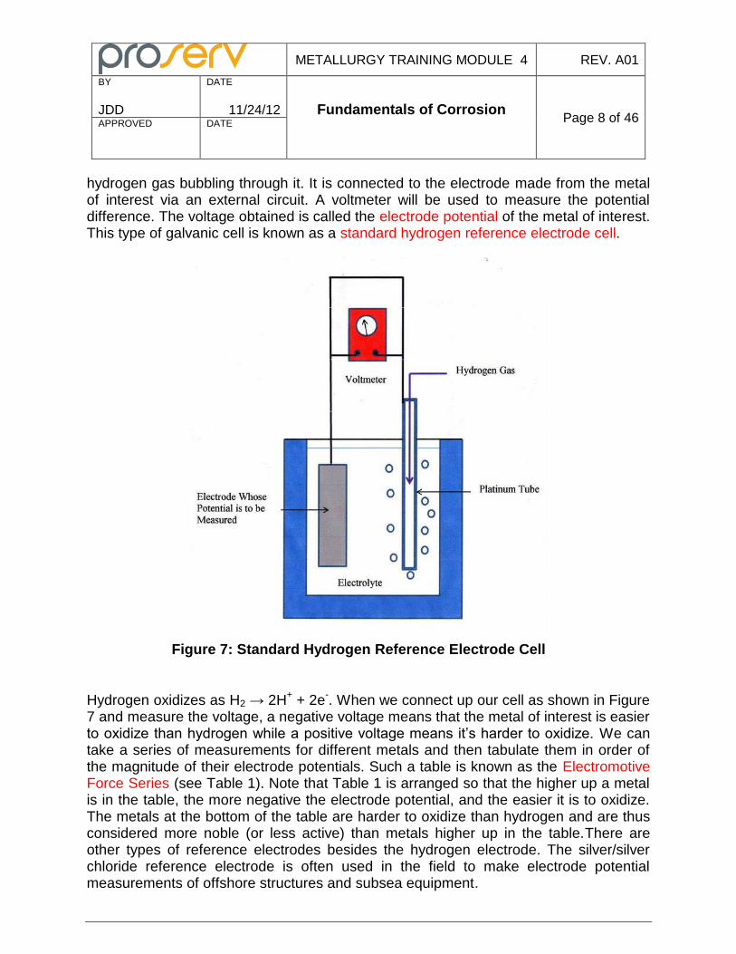
The weight loss type of corrosion that steel experiences in Oil Patch environments is electrochemical in nature. Electrochemistry deals with the chemical changes produced by electricity and the production of electricity by chemical changes. Most of our study of electrochemistry will focus on the various types of galvanic cells that can form in metals. Galvanic cells are named in honor of the Italian scientist Luigi Aloisio Galvani (1737-1798) who was among the first studied them. We’ll define a galvanic cell for the moment as two dissimilar electrodes connected via an external circuit that are immersed in an electrolyte. An electrolyte is an aqueous solution of ions that are capable of carrying a current. The potential difference between the electrodes will create a current until equilibrium is reached in the system. The iron that went into solution in our deaerated water produced positive ions and negative electrons. This creates an electrical potential whose magnitude is proportional to the number of atoms going into solution. If we could measure this potential we could quantify the tendency of the iron to go into solution or corrode. Potential; however, cannot be measured directly: voltage, or the difference between two potentials, can. We will measure the potential difference between an electrode made out of a metal of interest and a reference electrode in a galvanic cell using an arrangement as shown in Figure 7. The reference electrode is often a platinum tube (essentially inert) with
METALLURGY TRAINING MODULE 4 REV. A01
BY
JDD
DATE
11/24/12 Fundamentals of Corrosion
Page 8 of 46 APPROVED
DATE
hydrogen gas bubbling through it. It is connected to the electrode made from the metal of interest via an external circuit. A voltmeter will be used to measure the potential difference. The voltage obtained is called the electrode potential of the metal of interest. This type of galvanic cell is known as a standard hydrogen reference electrode cell.
Figure 7: Standard Hydrogen Reference Electrode Cell
Hydrogen oxidizes as H2 → 2H
+ + 2e
-. When we connect up our cell as shown in Figure
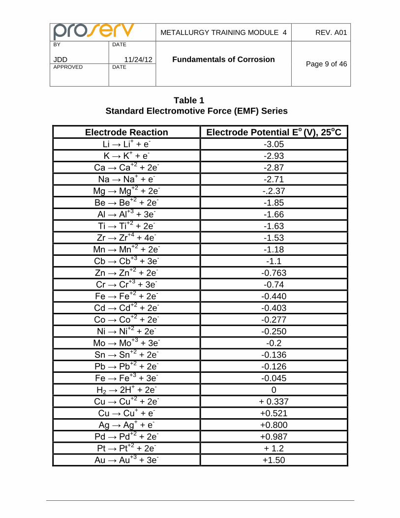
7 and measure the voltage, a negative voltage means that the metal of interest is easier to oxidize than hydrogen while a positive voltage means it’s harder to oxidize. We can take a series of measurements for different metals and then tabulate them in order of the magnitude of their electrode potentials. Such a table is known as the Electromotive Force Series (see Table 1). Note that Table 1 is arranged so that the higher up a metal is in the table, the more negative the electrode potential, and the easier it is to oxidize. The metals at the bottom of the table are harder to oxidize than hydrogen and are thus considered more noble (or less active) than metals higher up in the table.There are other types of reference electrodes besides the hydrogen electrode. The silver/silver chloride reference electrode is often used in the field to make electrode potential measurements of offshore structures and subsea equipment.
METALLURGY TRAINING MODULE 4 REV. A01
BY
JDD
DATE
11/24/12 Fundamentals of Corrosion
Page 9 of 46 APPROVED
DATE
Table 1
Standard Electromotive Force (EMF) Series
Electrode Reaction Electrode Potential Eo (V), 25oC
Li → Li+ + e
- -3.05
K → K+ + e
- -2.93
Ca → Ca+2
+ 2e- -2.87
Na → Na+ + e
- -2.71
Mg → Mg+2
+ 2e- -.2.37
Be → Be+2
+ 2e- -1.85
Al → Al+3
+ 3e- -1.66
Ti → Ti+2
+ 2e- -1.63
Zr → Zr+4
+ 4e- -1.53
Mn → Mn+2
+ 2e- -1.18
Cb → Cb+3
+ 3e- -1.1
Zn → Zn+2
+ 2e- -0.763
Cr → Cr+3
+ 3e- -0.74
Fe → Fe+2
+ 2e- -0.440
Cd → Cd+2
+ 2e- -0.403
Co → Co+2
+ 2e- -0.277
Ni → Ni+2
+ 2e- -0.250
Mo → Mo+3
+ 3e- -0.2
Sn → Sn+2
+ 2e- -0.136
Pb → Pb+2
+ 2e- -0.126
Fe → Fe+3
+ 3e- -0.045
H2 → 2H+ + 2e
- 0
Cu → Cu+2
+ 2e- + 0.337
Cu → Cu+ + e
- +0.521
Ag → Ag+ + e
- +0.800
Pd → Pd+2
+ 2e- +0.987
Pt → Pt+2
+ 2e- + 1.2
Au → Au+3
+ 3e- +1.50
METALLURGY TRAINING MODULE 4 REV. A01
BY
JDD
DATE
11/24/12 Fundamentals of Corrosion
Page 10 of 46 APPROVED
DATE
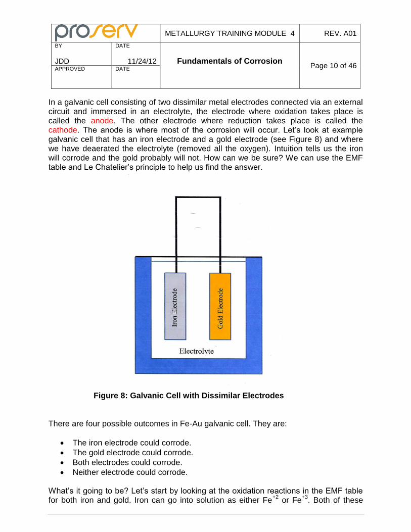
In a galvanic cell consisting of two dissimilar metal electrodes connected via an external circuit and immersed in an electrolyte, the electrode where oxidation takes place is called the anode. The other electrode where reduction takes place is called the cathode. The anode is where most of the corrosion will occur. Let’s look at example galvanic cell that has an iron electrode and a gold electrode (see Figure 8) and where we have deaerated the electrolyte (removed all the oxygen). Intuition tells us the iron will corrode and the gold probably will not. How can we be sure? We can use the EMF table and Le Chatelier’s principle to help us find the answer.
Figure 8: Galvanic Cell with Dissimilar Electrodes
There are four possible outcomes in Fe-Au galvanic cell. They are:
The iron electrode could corrode.
The gold electrode could corrode.
Both electrodes could corrode.
Neither electrode could corrode. What’s it going to be? Let’s start by looking at the oxidation reactions in the EMF table for both iron and gold. Iron can go into solution as either Fe
+2 or Fe
+3. Both of these
METALLURGY TRAINING MODULE 4 REV. A01
BY
JDD
DATE
11/24/12 Fundamentals of Corrosion
Page 11 of 46 APPROVED
DATE
reactions Fe → Fe+2
+ 2e- and Fe → Fe
+3 + 3e
- have more negative electrode potentials
than Au → Au+3
+ 3e- and thus oxidize easier. The iron will go into solution as the
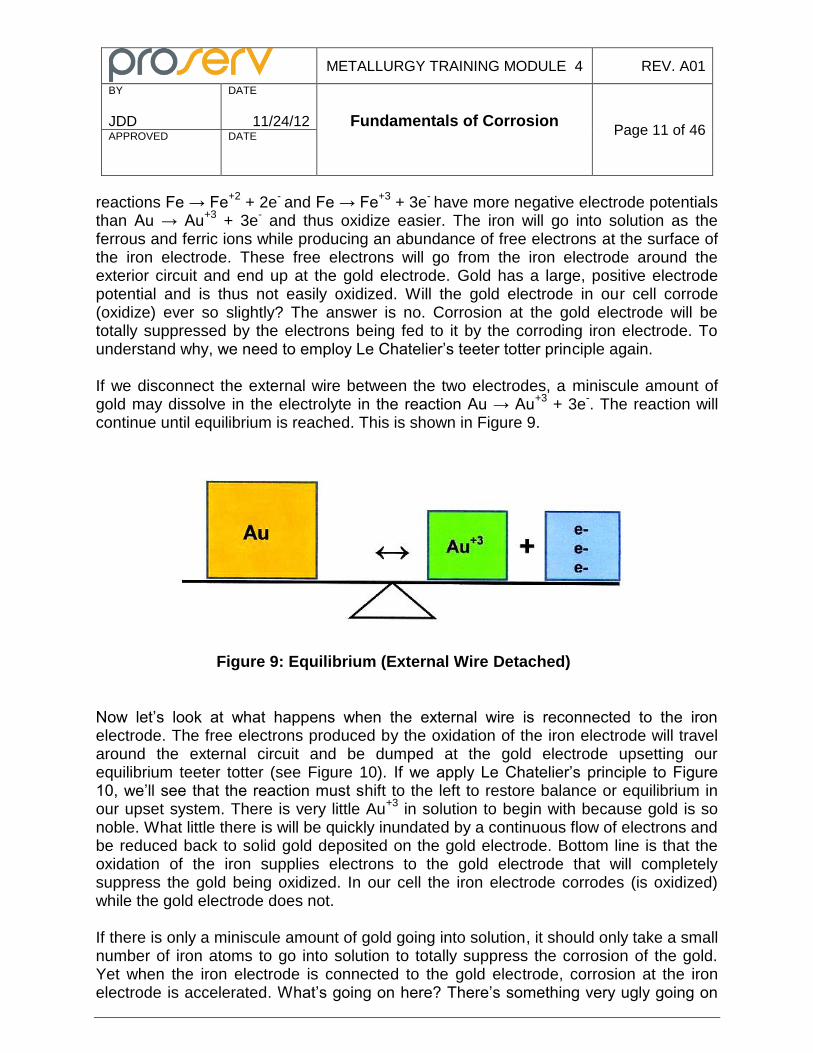
ferrous and ferric ions while producing an abundance of free electrons at the surface of the iron electrode. These free electrons will go from the iron electrode around the exterior circuit and end up at the gold electrode. Gold has a large, positive electrode potential and is thus not easily oxidized. Will the gold electrode in our cell corrode (oxidize) ever so slightly? The answer is no. Corrosion at the gold electrode will be totally suppressed by the electrons being fed to it by the corroding iron electrode. To understand why, we need to employ Le Chatelier’s teeter totter principle again. If we disconnect the external wire between the two electrodes, a miniscule amount of gold may dissolve in the electrolyte in the reaction Au → Au
+3 + 3e
-. The reaction will
continue until equilibrium is reached. This is shown in Figure 9.
Figure 9: Equilibrium (External Wire Detached)
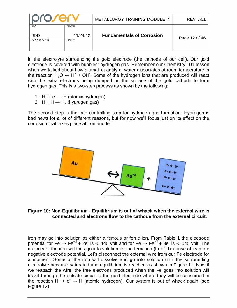
Now let’s look at what happens when the external wire is reconnected to the iron electrode. The free electrons produced by the oxidation of the iron electrode will travel around the external circuit and be dumped at the gold electrode upsetting our equilibrium teeter totter (see Figure 10). If we apply Le Chatelier’s principle to Figure 10, we’ll see that the reaction must shift to the left to restore balance or equilibrium in our upset system. There is very little Au
+3 in solution to begin with because gold is so
noble. What little there is will be quickly inundated by a continuous flow of electrons and be reduced back to solid gold deposited on the gold electrode. Bottom line is that the oxidation of the iron supplies electrons to the gold electrode that will completely suppress the gold being oxidized. In our cell the iron electrode corrodes (is oxidized) while the gold electrode does not. If there is only a miniscule amount of gold going into solution, it should only take a small number of iron atoms to go into solution to totally suppress the corrosion of the gold. Yet when the iron electrode is connected to the gold electrode, corrosion at the iron electrode is accelerated. What’s going on here? There’s something very ugly going on
METALLURGY TRAINING MODULE 4 REV. A01
BY
JDD
DATE
11/24/12 Fundamentals of Corrosion
Page 12 of 46 APPROVED
DATE
in the electrolyte surrounding the gold electrode (the cathode of our cell). Our gold electrode is covered with bubbles: hydrogen gas. Remember our Chemistry 101 lesson when we talked about how a small quantity of water dissociates at room temperature in the reaction H2O ↔ H
+ + OH
-. Some of the hydrogen ions that are produced will react
with the extra electrons being dumped on the surface of the gold cathode to form hydrogen gas. This is a two-step process as shown by the following:
1. H+ + e
- → H (atomic hydrogen)
2. H + H → H2 (hydrogen gas) The second step is the rate controlling step for hydrogen gas formation. Hydrogen is bad news for a lot of different reasons, but for now we’ll focus just on its effect on the corrosion that takes place at iron anode.
Figure 10: Non-Equilibrium - Equilibrium is out of whack when the external wire is
connected and electrons flow to the cathode from the external circuit.
Iron may go into solution as either a ferrous or ferric ion. From Table 1 the electrode potential for Fe → Fe
+2 + 2e
- is -0.440 volt and for Fe → Fe
+3 + 3e
- is -0.045 volt. The
majority of the iron will thus go into solution as the ferric ion (Fe+3) because of its more
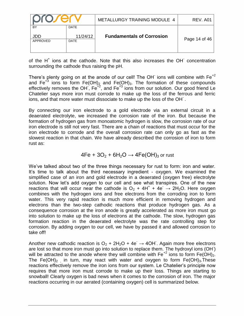
negative electrode potential. Let’s disconnect the external wire from our Fe electrode for a moment. Some of the iron will dissolve and go into solution until the surrounding electrolyte because saturated and equilibrium is reached as shown in Figure 11. Now if we reattach the wire, the free electrons produced when the Fe goes into solution will travel through the outside circuit to the gold electrode where they will be consumed in the reaction H
+ + e
- → H (atomic hydrogen). Our system is out of whack again (see
Figure 12).
METALLURGY TRAINING MODULE 4 REV. A01
BY
JDD
DATE
11/24/12 Fundamentals of Corrosion
Page 13 of 46 APPROVED
DATE
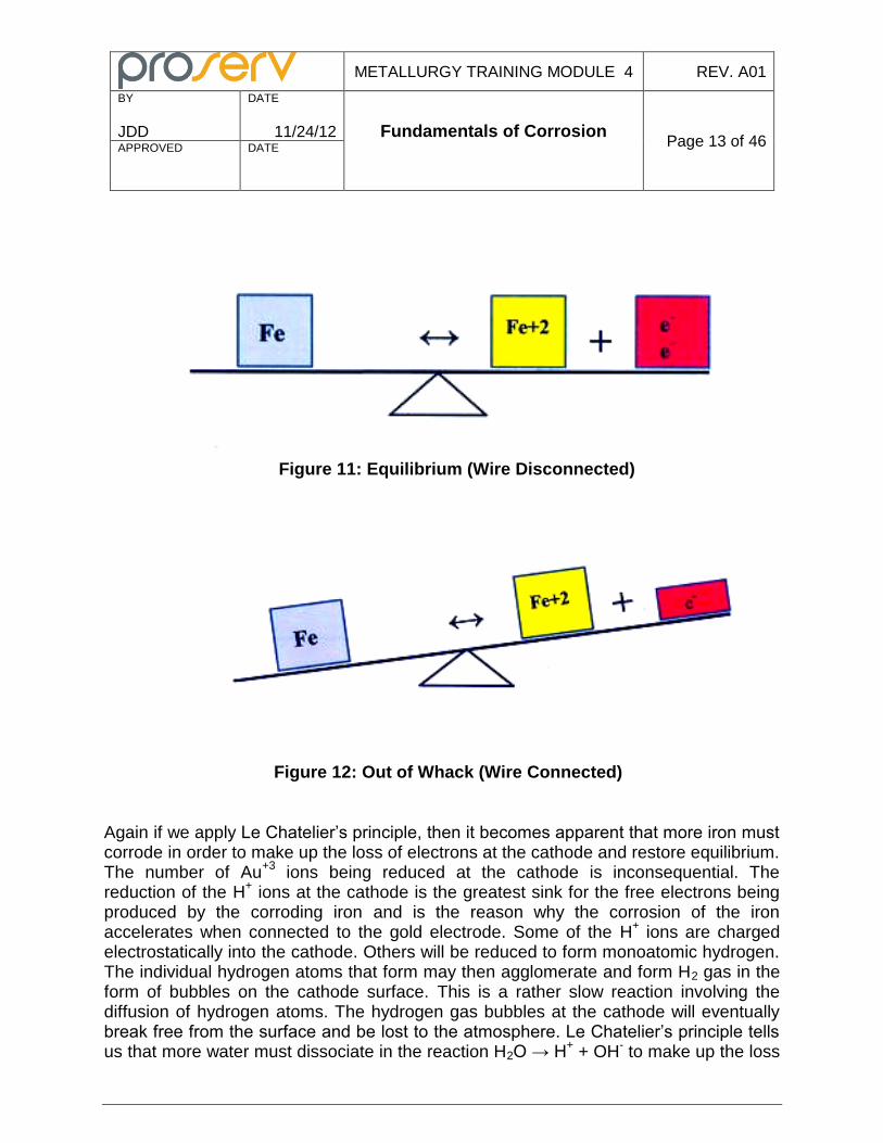
Figure 11: Equilibrium (Wire Disconnected)
Figure 12: Out of Whack (Wire Connected)
Again if we apply Le Chatelier’s principle, then it becomes apparent that more iron must corrode in order to make up the loss of electrons at the cathode and restore equilibrium. The number of Au
+3 ions being reduced at the cathode is inconsequential. The
reduction of the H+ ions at the cathode is the greatest sink for the free electrons being
produced by the corroding iron and is the reason why the corrosion of the iron accelerates when connected to the gold electrode. Some of the H
+ ions are charged
electrostatically into the cathode. Others will be reduced to form monoatomic hydrogen. The individual hydrogen atoms that form may then agglomerate and form H2 gas in the form of bubbles on the cathode surface. This is a rather slow reaction involving the diffusion of hydrogen atoms. The hydrogen gas bubbles at the cathode will eventually break free from the surface and be lost to the atmosphere. Le Chatelier’s principle tells us that more water must dissociate in the reaction H2O → H
+ + OH
- to make up the loss
METALLURGY TRAINING MODULE 4 REV. A01
BY
JDD
DATE
11/24/12 Fundamentals of Corrosion
Page 14 of 46 APPROVED
DATE
of the H+ ions at the cathode. Note that this also increases the OH
- concentration
surrounding the cathode thus raising the pH. There’s plenty going on at the anode of our cell! The OH
- ions will combine with Fe
+2
and Fe+3
ions to form Fe(OH)2 and Fe(OH)3. The formation of these compounds effectively removes the OH
-, Fe
+2, and Fe
+3 ions from our solution. Our good friend Le
Chatelier says more iron must corrode to make up the loss of the ferrous and ferric ions, and that more water must dissociate to make up the loss of the OH
- .
By connecting our iron electrode to a gold electrode via an external circuit in a deaerated electrolyte, we increased the corrosion rate of the iron. But because the formation of hydrogen gas from monoatomic hydrogen is slow, the corrosion rate of our iron electrode is still not very fast. There are a chain of reactions that must occur for the iron electrode to corrode and the overall corrosion rate can only go as fast as the slowest reaction in that chain. We have already described the corrosion of iron to form rust as:
4Fe + 3O2 + 6H2O → 4Fe(OH)3 or rust
We’ve talked about two of the three things necessary for rust to form: iron and water. It’s time to talk about the third necessary ingredient - oxygen. We examined the simplified case of an iron and gold electrode in a deaerated (oxygen free) electrolyte solution. Now let’s add oxygen to our cell and see what transpires. One of the new reactions that will occur near the cathode is O2 + 4H
+ + 4e
- → 2H2O. Here oxygen
combines with the hydrogen ions and free electrons from the corroding iron to form water. This very rapid reaction is much more efficient in removing hydrogen and electrons than the two-step cathodic reactions that produce hydrogen gas. As a consequence corrosion at the iron anode is greatly accelerated as more iron must go into solution to make up the loss of electrons at the cathode. The slow, hydrogen gas formation reaction in the deaerated electrolyte was the rate controlling step for corrosion. By adding oxygen to our cell, we have by passed it and allowed corrosion to take off! Another new cathodic reaction is O2 + 2H2O + 4e
- → 4OH
-. Again more free electrons
are lost so that more iron must go into solution to replace them. The hydroxyl ions (OH-)
will be attracted to the anode where they will combine with Fe+2
ions to form Fe(OH)2. The Fe(OH)2 , in turn, may react with water and oxygen to form Fe(OH)3.These reactions effectively remove the iron ions from our system. Le Chatelier’s principle now requires that more iron must corrode to make up their loss. Things are starting to snowball! Clearly oxygen is bad news when it comes to the corrosion of iron. The major reactions occurring in our aerated (containing oxygen) cell is summarized below.
METALLURGY TRAINING MODULE 4 REV. A01
BY
JDD
DATE
11/24/12 Fundamentals of Corrosion
Page 15 of 46 APPROVED
DATE
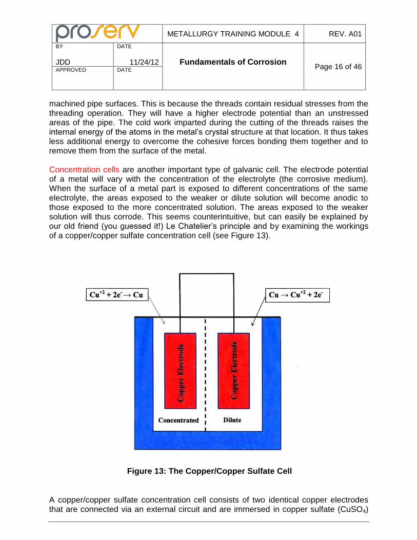
Anodic Reactions Occurring at the Iron Electrode:
Fe → Fe+2 + 2e- Fe+2 + 2(0H-) ↔ Fe(OH)2 4Fe(OH)2 + 2H2O + O2 → 4Fe(OH)3 Cathodic Reactions Occurring at the Gold Electrode
2H+ +2e- → H2 4H+ +O2 +4e- →2H20 O2 + 2H2O + 4e- → 4OH-
Well we have beat Le Chatelier’s principle to a pulp in this section, but you can see how useful it is in explaining what’s going on in a galvanic cell. It’s relatively easy to apply the teeter totter principle to the above reactions and explain why corrosion of the iron sky rockets when oxygen is introduced into our cell. We examined a cell with iron and gold electrodes, but the principles are the same for other combinations of metals. The metal with the more negative potential in the EMF table is more easily oxidized and will become the anode. Oxidation (corrosion) takes place at the anode. The metal with the more positive potential in the EMF table is more noble (less easily oxidized) and will become the cathode of our galvanic cell. Reduction takes place at the cathode. The greater the difference in electrode potentials between the anode and cathode, the greater the driving force for corrosion at the anode. Conversely, the smaller the difference, the lower the driving force. If the driving force is insignificant in a given environment, then that combination of metals is said to be “compatible” in that environment.
Other Types of Galvanic Cells
The Fe-Au dissimilar metal cell we just talked about is an example of composition galvanic cell. A composition galvanic cell consists of two different types of metals in electrical contact and immersed in an electrolyte. Composition galvanic cells may become established on the surface of a metal part if there is enough variation in the local composition. For example duplex stainless steels have a microstructure consisting of roughly equal amount of ferrite and austenite. The austenite and ferrite phases have significantly different compositions. In some environments, the ferrite phase will become the anode of a galvanic cell and preferentially corrode. Another type of galvanic cell is called the stress cell. If you have ever visited a pipe yard you may have noticed that the pipe threads tend to corrode faster than the non-
METALLURGY TRAINING MODULE 4 REV. A01
BY
JDD
DATE
11/24/12 Fundamentals of Corrosion
Page 16 of 46 APPROVED
DATE
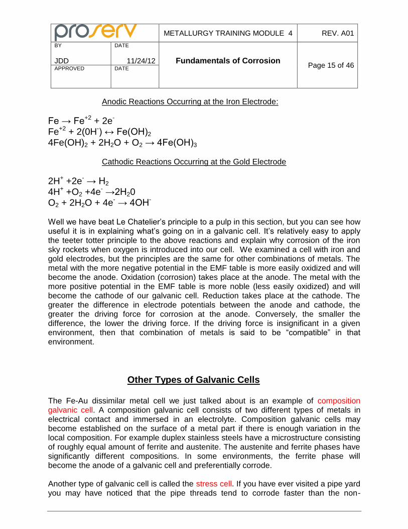
machined pipe surfaces. This is because the threads contain residual stresses from the threading operation. They will have a higher electrode potential than an unstressed areas of the pipe. The cold work imparted during the cutting of the threads raises the internal energy of the atoms in the metal’s crystal structure at that location. It thus takes less additional energy to overcome the cohesive forces bonding them together and to remove them from the surface of the metal. Concentration cells are another important type of galvanic cell. The electrode potential of a metal will vary with the concentration of the electrolyte (the corrosive medium). When the surface of a metal part is exposed to different concentrations of the same electrolyte, the areas exposed to the weaker or dilute solution will become anodic to those exposed to the more concentrated solution. The areas exposed to the weaker solution will thus corrode. This seems counterintuitive, but can easily be explained by our old friend (you guessed it!) Le Chatelier’s principle and by examining the workings of a copper/copper sulfate concentration cell (see Figure 13).
Figure 13: The Copper/Copper Sulfate Cell
A copper/copper sulfate concentration cell consists of two identical copper electrodes that are connected via an external circuit and are immersed in copper sulfate (CuSO4)
METALLURGY TRAINING MODULE 4 REV. A01
BY
JDD
DATE
11/24/12 Fundamentals of Corrosion
Page 17 of 46 APPROVED
DATE
solutions of different strengths. The copper sulfate salt dissociates into Cu+2
and SO4-2
ions forming the electrolyte. The cell itself is divided in two by a semi-permeable membrane that allows the flow of current. One side of the cell has a dilute solution of copper sulfate while the other is concentrated. The copper will corrode or go into solution until equilibrium is reached according to Cu ↔ Cu
+2 + 2e
-. The dearth of copper
ions in the dilute side will shift the equilibrium point of this reaction to the right. The abundance of copper ions in the concentrated side will shift it to the left. The copper electrode in the dilute solution will have to corrode to provide more Cu
+2 ions and thus
become the anode. The electrons freed up by oxidation taking place at the anode travel via the external circuit to the copper electrode in the concentrated solution. Here they combine (reduce) some of the Cu
+2 ions which then plate out on the electrode as
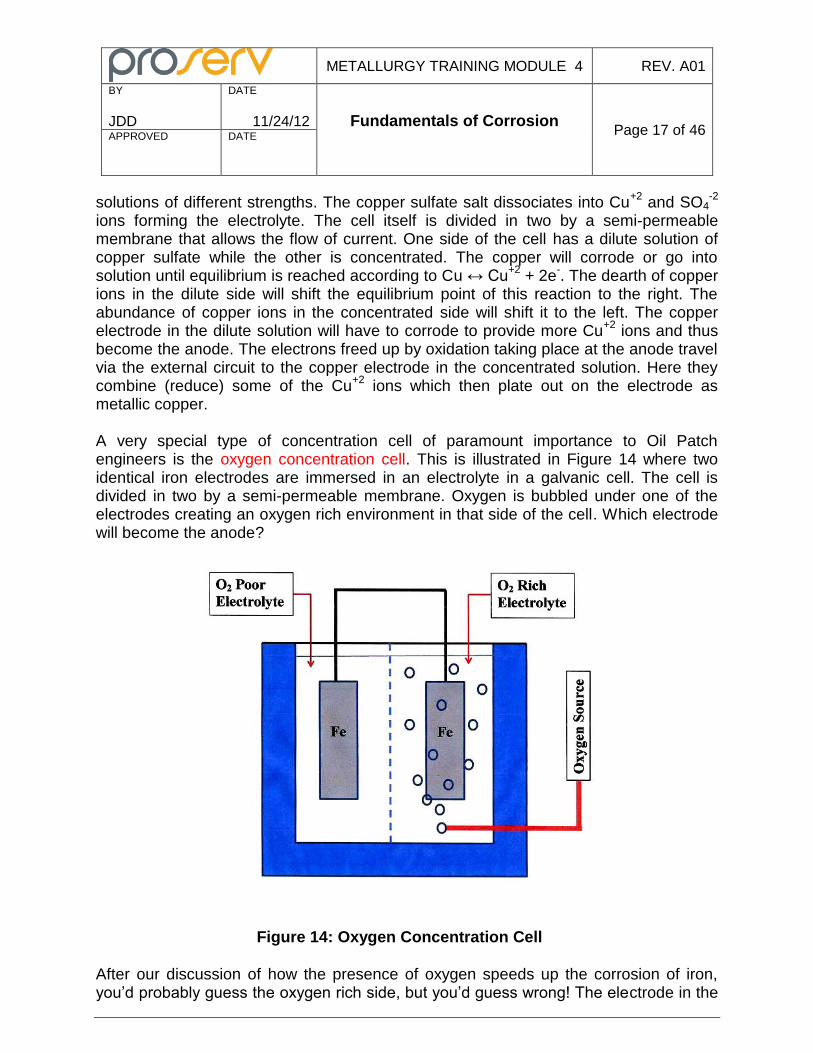
metallic copper. A very special type of concentration cell of paramount importance to Oil Patch engineers is the oxygen concentration cell. This is illustrated in Figure 14 where two identical iron electrodes are immersed in an electrolyte in a galvanic cell. The cell is divided in two by a semi-permeable membrane. Oxygen is bubbled under one of the electrodes creating an oxygen rich environment in that side of the cell. Which electrode will become the anode?
Figure 14: Oxygen Concentration Cell
After our discussion of how the presence of oxygen speeds up the corrosion of iron, you’d probably guess the oxygen rich side, but you’d guess wrong! The electrode in the
METALLURGY TRAINING MODULE 4 REV. A01
BY
JDD
DATE
11/24/12 Fundamentals of Corrosion
Page 18 of 46 APPROVED
DATE
oxygen poor side will become the anode. This seems counterintuitive, but Le Chatelier’s principle will once again come to our rescue and help us solve this conundrum. One of the cathodic reactions that we examined was O2 + 2H2O + 4e
- → 4OH
-. By adding more
oxygen to the electrode where this reaction is occurring (the cathode), we move the equilibrium point in favor of the OH
-. As we produce more hydroxyl ions, we use up
some of the free electrons supplied by the anode. The anode must make up this loss by corroding faster and producing more electrons. The electrode in the high oxygen electrolyte is thus the cathode and the electrode in the low oxygen electrolyte is the anode. Oxygen concentration cells are responsible for a great deal of corrosion damage on our type of equipment. They can form wherever there is a crevice, a pit, overlapping surfaces, etc. where oxygen can be depleted through corrosion reactions, but cannot easily be replenished. Let’s look at some examples. Consider a threaded steel pipe connection subsea. Water will seep in between the threads and cause some corrosion. This depletes the water of oxygen. Seawater cannot easily flow into the joint and replenish the oxygen. The pipe surfaces just outside the joint will constantly be swept by seawater that is well oxygenated. The threaded area will become the anode of an oxygen concentration cell while the surrounding surfaces of the pipe will be the cathode. Because the exposed surface of the pipe is so much greater than the threaded area, corrosion of the threads will be very rapid. An open storage tank partially filled with water will corrode just below the water line. The area immediately adjacent to the water line will be rich in oxygen while the area just below will be poor in oxygen. Corrosion will result in a ring of lost metal just below the surface. Mill scale or any type of partial surface deposit on a steel pipe may result in the creation of an oxygen concentration cell. The bare surface of the pipe will be well oxygenated while the area underneath the scale or deposit will be oxygen poor and become the anode. If the scale or deposit is relatively isolated, then the cathode-to-anode surface area ratio may be quite large. This may result in the formation of a pit underneath the scale or deposit that may rapidly perforate the pipe. The final type of galvanic cell is known as a differential temperature cell. Here the anode and cathode consist of the same type of metal, but are exposed to different temperatures. They may be on the same part or on different parts that are immersed in the same electrolyte. Not all metals behave the same way in a differential temperature cell. Copper and lead, for example, will corrode at the lower temperature while the area at the higher temperature will be the cathode. The copper or lead will dissolve at the low temperature and then deposit on the surfaces at the higher temperature. For silver, the situation is reversed: the area exposed to the high temperature is the anode and to the low temperature the cathode. Steels in dilute, oxygenated chloride solutions will generally have the anode in the warmer temperature electrolyte and the cathode at the
METALLURGY TRAINING MODULE 4 REV. A01
BY
JDD
DATE
11/24/12 Fundamentals of Corrosion
Page 19 of 46 APPROVED
DATE
lower, but the polarity may reverse as the reaction progresses depending on a number of other factors including the amount of oxygen available, the velocity of the electrolyte, etc. Differential temperature cells are generally not a problem for our type of equipment because a substantial difference in temperature must exist between the inlet and outlet surfaces of the equipment exposed to the same electrolyte for differential temperature cell corrosion to be significant. It is most often encountered in heat exchangers, boilers, etc. This completes our survey of galvanic cells. The corrosion that actually takes place on a part is often the result of a combination of different types of galvanic cells. For example, suppose a stainless steel part is set on a pallet and a carbon steel shaving gets embedded in its surface. When the part is placed in service and is exposed to sea- water, the carbon steel will become the anode of a dissimilar metal (composition) cell. It will rapidly corrode leaving a pit at the surface. This in turn may create the conditions ripe for an oxygen concentration cell. As the pit grows, the composition of the electrolyte within the pit may change from the surrounding seawater and create additional concentration cells within the pit. Corrosion is a complex business!
Corrosion Kinetics
The information presented in the EMF table was very useful in determining the ease with which a metal can be oxidized. It allowed us to predict which metal in a dissimilar metal cell would become the anode. Looking at gold, platinum, palladium, and silver in the table we see they’re all at the bottom (have the highest positive electrode potential) and therefore are very noble (not likely to corrode). This fits well with our common experience with these metals. Now look at aluminum. At -1.66 volt for its standard electrode potential it’s relatively high up the table so it’s easily oxidized, yet we use aluminum for pots and pans for cooking, for boats, etc. because of its good corrosion resistance! What’s going on here? Well it turns out that easily oxidized doesn’t necessarily equate to a high corrosion rate. Kinetics is the study of the rate of chemical reactions. In the case of aluminum, the surface of the aluminum is very easily oxidized by reacting with oxygen, but the oxide forms a tenacious, continuous, impervious film on the surface of the part. This is aluminum’s armor: it isolates the rest of the aluminum for the corrosive environment. Yes, the aluminum was easily oxidized as predicted by the EMF table, but the EMF table couldn’t predict that the rate of corrosion would be very low because of the protective oxide layer that formed. The EMF table has limited use in predicting the actual amount of corrosion that will occur in a given environment because it doesn’t consider the kinetics of corrosion. In this section we’ll examine some of the important factors that do determine the nature of the corrosion and how fast it may occur.
METALLURGY TRAINING MODULE 4 REV. A01
BY
JDD
DATE
11/24/12 Fundamentals of Corrosion
Page 20 of 46 APPROVED
DATE
Consider the copper/copper sulfate concentration cell that we talked about earlier (refer back to Figure 13). This consisted of two identical copper electrodes immersed in electrolytes of different concentrations of copper sulfate. We used Le Chatelier’s rule to show that the electrode in the weak solution became the anode and corroded, while the electrode in the concentrated solution became the cathode and had additional copper plate out on it. The initial driving force for this reaction may be quite strong, but what happens over a period of time? In our closed system, the weak solution is becoming richer and richer in Cu
+2 ions as the anode corrodes. The concentrated solution, on the
other hand, is getting weaker and weaker as copper ions are reduced and plate out on the cathode. You can see where this is going. The difference in electrode potential (voltage) between the two copper electrodes becomes less and less as the concentration of the copper ions in the electrolytes begin to approach each other. Eventually the corrosion will stop and equilibrium will be reached. The cell has become polarized. Polarization is the voltage drop in an electrochemical cell caused by the continuous operation of the cell. It is a measure of how the rates of reactions at the anode and cathode are slowed down by various environmental factors such as changes in metal ion concentration, oxygen content, etc. or by surface process factors such as absorption, film formation, etc. Concentration polarization typically occurs at the cathode because of a lack of reactants immediately adjacent to the surface where there is a gradient in the ion concentration in the electrolyte. As the ions are used up in chemical reactions at the cathode, they must be made up by additional ions diffusing through the depleted layer. This diffusion becomes the rate controlling step for corrosion. Activation polarization typically occurs when a surface film is formed on the anode or cathode. This makes it more difficult for ions in the electrolyte to reach the electrode’s surface effectively isolating it from the environment. The film formation may involve a series of reactions; the slowest of which will be the rate controlling step. Hydrogen formation at the cathode of our Fe-Au dissimilar metal cell is an example of activation polarization. As previously mentioned it is a two-step process with hydrogen ions first being reduced and then combining to form hydrogen gas. As the hydrogen atoms are formed they blanket the surface of the cathode making it more difficult for ions to reach the surface. The rate controlling step is the formation of H2 gas. This is a relatively slow process: If it were rapid the adsorbed hydrogen atoms on the surface would quickly form hydrogen gas bubbles and be lost to the atmosphere. They would not accumulate and form a protective shield. Another important example of activation polarization is the calcareous deposit that forms when we cathodically protect a steel structure in seawater. We’ll discuss this in detail in the training module on Marine Corrosion. We introduced this section by describing how a protective oxide layer forms on aluminum in many environments. Aluminum has a strong tendency to oxidize as
METALLURGY TRAINING MODULE 4 REV. A01
BY
JDD
DATE
11/24/12 Fundamentals of Corrosion
Page 21 of 46 APPROVED
DATE
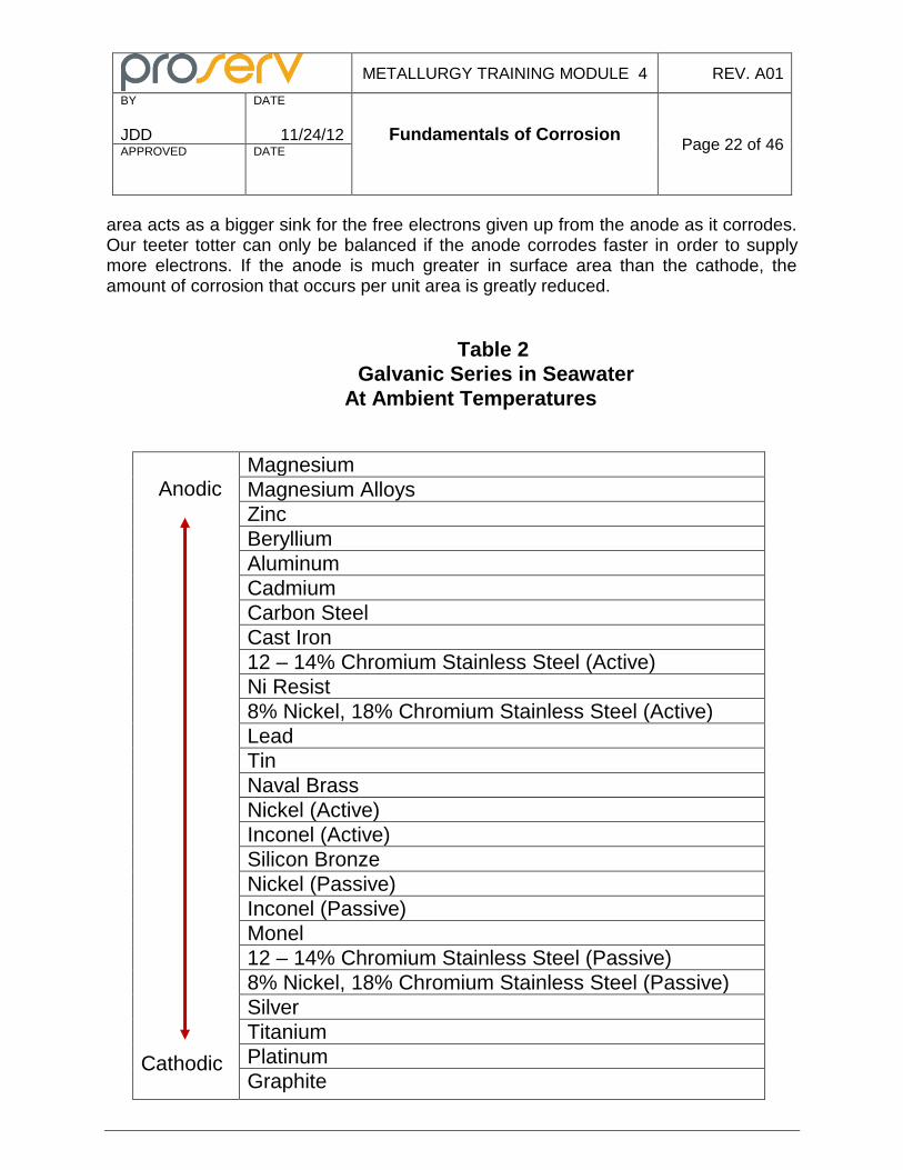
evidence by its position in the EMF table, but this does not necessarily equate to a high corrosion rate. Metals that have the ability to form corrosion products that tightly adhere to their surface and form a permanent, impervious barrier to the surrounding environment are said to have been passivated. While this protective layer may not entirely prevent further corrosion, it will greatly retard its rate. We use many “corrosion resistant alloys” or CRA’s in the Oil Patch the majority of which are in the passive condition because of a protective surface layer of corrosion products (typically an oxide). These include stainless steels, titanium alloys, aluminum alloys, and nickel base alloys. In environments where the protective surface layer cannot form, the metal may be in the active state or condition and freely corrode. Clearly there are some shortcomings in trying to use the EMF table to predict if significant corrosion will occur. It does not take into account passivity. Depending on the environment (the corrosive media), electrode potentials will change and the relative positions of the metals within the table may change. The galvanic series was developed to overcome these shortcomings. A galvanic series is a list of metals in order of their tendency to oxidize in comparison to a standard calomel electrode (SCE) in a specific environment at a given set of conditions (temperature, etc.). Table 2 shows the galvanic series for seawater at ambient temperatures. Metals high in the table are anodic to those below them. If a metal A is coupled to a different metal B that is lower in the table and immersed in seawater, metal A will become the anode and may corrode. The farther apart the metals are in the table, the greater the driving force for corrosion. If the difference is in hundreds of millivolts, galvanic corrosion may be severe. If the difference is in tens of millivolts, corrosion will probably not be an issue and the metals are compatible. You will note in Table 2 that some metals are listed twice: once in the active condition and then again in the passive. It can make a big difference! The metal may switch from active to passive or passive to active depending on changing environmental conditions. It is important to know what types of environments are conducive to promoting the passive condition and which environments may attack and breach the protective surface layer and lead to active corrosion. Many of the alloys we use depend upon a protective oxide surface film. The film is attacked by halide ions with chlorides being the worst offenders because they are so common in Oil Patch environments. Many CRA’s are carefully alloyed to strengthen this film and make it more resistant to halide attack. Increased chromium, nitrogen, and especially molybdenum are often used for this purpose. Just because a metal is high up in Table 2 does not mean it will corrode rapidly in seawater. It must be coupled to another metal lower in the table for a galvanic corrosion to occur. Aluminum, for example is used in making Navy ship boat hulls that are quite resistant to corrosion in seawater. The relative sizes (surface areas) of the anode and cathode play a significant role in the anode’s corrosion rate. The greater the cathode-to-anode size ratio, the more accelerated anode corrosion becomes. The larger cathode
METALLURGY TRAINING MODULE 4 REV. A01
BY
JDD
DATE
11/24/12 Fundamentals of Corrosion
Page 22 of 46 APPROVED
DATE
area acts as a bigger sink for the free electrons given up from the anode as it corrodes. Our teeter totter can only be balanced if the anode corrodes faster in order to supply more electrons. If the anode is much greater in surface area than the cathode, the amount of corrosion that occurs per unit area is greatly reduced.
Table 2
Galvanic Series in Seawater
At Ambient Temperatures
Anodic Cathodic
Magnesium
Magnesium Alloys
Zinc
Beryllium
Aluminum
Cadmium
Carbon Steel
Cast Iron
12 – 14% Chromium Stainless Steel (Active)
Ni Resist
8% Nickel, 18% Chromium Stainless Steel (Active)
Lead
Tin
Naval Brass
Nickel (Active)
Inconel (Active)
Silicon Bronze
Nickel (Passive)
Inconel (Passive)
Monel
12 – 14% Chromium Stainless Steel (Passive)
8% Nickel, 18% Chromium Stainless Steel (Passive)
Silver
Titanium
Platinum
Graphite
METALLURGY TRAINING MODULE 4 REV. A01
BY
JDD
DATE
11/24/12 Fundamentals of Corrosion
Page 23 of 46 APPROVED
DATE
In an electrochemical cell, current flows from the anode to the cathode via the external circuit and then back to the anode through the electrolyte. There is a voltage drop associated with the current flow through the electrolyte. Ohm’s law states that the current through a conductor between two points is directly proportional to the potential difference across the two points or V=IR where V is volts, I is the current in amperes, and R is the resistance in ohms. The resistance of the electrolyte to our corrosion current is dependent on several factors. It is of course strongly dependent on the concentration of the ions that make it conductive. The resistance of the electrolyte is also a function of the distance between the anode and the cathode – the farther apart they are, the greater the resistance. The larger the subsequent voltage drop, or IR drop as it is typically called, between the anode and cathode, the lower driving force for corrosion. The bottom line for all this is that an anode/cathode combination in a given electrolyte will undergo less corrosion if they are farther apart than if they are closer together. Temperature plays a critical role in establishing corrosion rates. For most corrosive processes that affect our equipment, the higher the temperature, the greater the rate of corrosion, but there are some exceptions. You may remember the old rule of thumb from Chemistry 101 that the rate of a chemical reaction approximately doubles for every 10
oC rise in temperature. This certainly will speed up corrosion reactions at the anode
and cathode, but there are some mitigating effects that may occur. The solubility of gases that impact corrosion (such as oxygen) becomes less in water as temperature increases. Protective scales may form on a metal’s surface as the temperature is raised that will greatly reduce the rate of corrosion. In the electrochemical cells we’ve examined so far the electrolyte is stationary. In real life the electrolyte can flow relative to a metal’s surface. Does this impact the corrosion rate? You bet it does! But its effect is a mixed bag. Sometimes it will increase corrosion; sometimes it will reduce corrosion depending on circumstances and the metals involved. Concentration cells that form pits on steel in seawater, for example, will grow more rapidly in stagnant water than in flowing seawater. Flowing seawater tends to flush out the pits and prevent a concentration gradient from getting established thus reducing the rate of corrosion. On the other hand, a flowing electrolyte may increase corrosion through several different mechanisms. It may erode off protective scale or adherent corrosion products thus exposing fresh metal to corrode. It will reduce concentration polarization by reducing the thickness of the depleted boundary layer through which ions must diffuse to reach the surface of the metal. And finally a flowing electrolyte with a low concentration of a corrodent (a corrosive substance) may actually deliver more of that corrodent to the surface of a metal than a stagnant electrolyte rich in that corrodent. There are other important velocity effects as well that we’ll discuss in the training module on Wellhead Corrosion.
METALLURGY TRAINING MODULE 4 REV. A01
BY
JDD
DATE
11/24/12 Fundamentals of Corrosion
Page 24 of 46 APPROVED
DATE
Types of Corrosion Damage
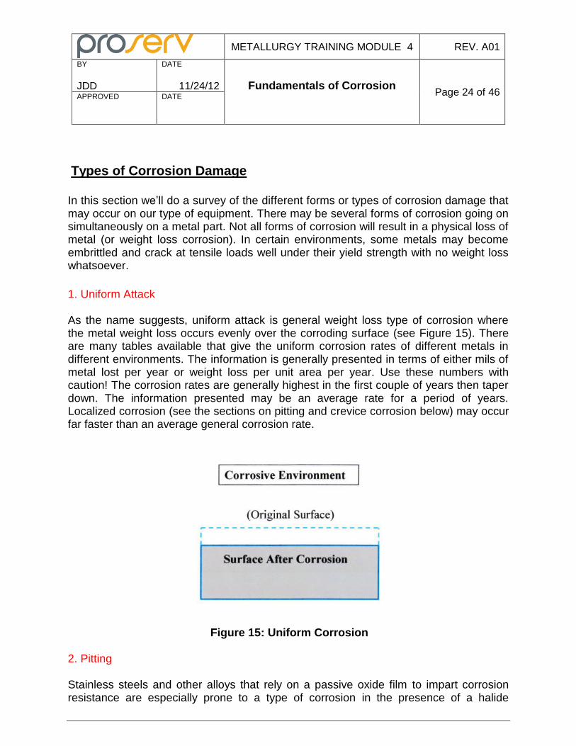
In this section we’ll do a survey of the different forms or types of corrosion damage that may occur on our type of equipment. There may be several forms of corrosion going on simultaneously on a metal part. Not all forms of corrosion will result in a physical loss of metal (or weight loss corrosion). In certain environments, some metals may become embrittled and crack at tensile loads well under their yield strength with no weight loss whatsoever. 1. Uniform Attack As the name suggests, uniform attack is general weight loss type of corrosion where the metal weight loss occurs evenly over the corroding surface (see Figure 15). There are many tables available that give the uniform corrosion rates of different metals in different environments. The information is generally presented in terms of either mils of metal lost per year or weight loss per unit area per year. Use these numbers with caution! The corrosion rates are generally highest in the first couple of years then taper down. The information presented may be an average rate for a period of years. Localized corrosion (see the sections on pitting and crevice corrosion below) may occur far faster than an average general corrosion rate.
Figure 15: Uniform Corrosion 2. Pitting Stainless steels and other alloys that rely on a passive oxide film to impart corrosion resistance are especially prone to a type of corrosion in the presence of a halide
METALLURGY TRAINING MODULE 4 REV. A01
BY
JDD
DATE
11/24/12 Fundamentals of Corrosion
Page 25 of 46 APPROVED
DATE
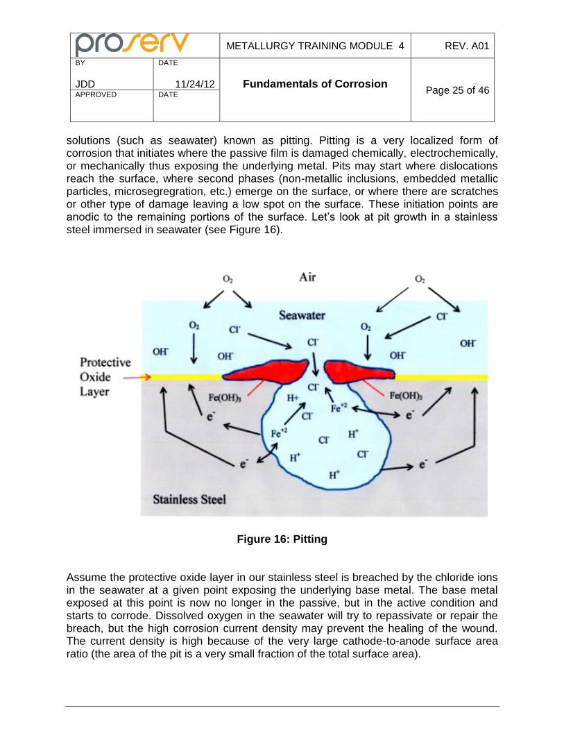
solutions (such as seawater) known as pitting. Pitting is a very localized form of corrosion that initiates where the passive film is damaged chemically, electrochemically, or mechanically thus exposing the underlying metal. Pits may start where dislocations reach the surface, where second phases (non-metallic inclusions, embedded metallic particles, microsegregration, etc.) emerge on the surface, or where there are scratches or other type of damage leaving a low spot on the surface. These initiation points are anodic to the remaining portions of the surface. Let’s look at pit growth in a stainless steel immersed in seawater (see Figure 16).
Figure 16: Pitting Assume the protective oxide layer in our stainless steel is breached by the chloride ions in the seawater at a given point exposing the underlying base metal. The base metal exposed at this point is now no longer in the passive, but in the active condition and starts to corrode. Dissolved oxygen in the seawater will try to repassivate or repair the breach, but the high corrosion current density may prevent the healing of the wound. The current density is high because of the very large cathode-to-anode surface area ratio (the area of the pit is a very small fraction of the total surface area).
METALLURGY TRAINING MODULE 4 REV. A01
BY
JDD
DATE
11/24/12 Fundamentals of Corrosion
Page 26 of 46 APPROVED
DATE
Inside the pit the iron will go into solution as Fe → Fe+2
+ 2e-. The free electrons that
are produced travel to the passivated surface of the part where they react with oxygen and water in the cathodic reaction O2 + 2H2O + 4e
- → 4OH
-. The surface of the part
will become increasing more negative. The environment within the pit becomes increasingly more positive as positive ferrous ions are produced as iron atoms go into solution. Negatively charged chloride ions in the seawater are attracted to the positively charged iron ions in the pit. The two ions will meet and react with water in the reaction FeCl2 + 2H2O → Fe(OH)2 + 2HCl. The Fe(OH)2 deposits on the surface of the passive area surrounding the mouth of the pit and begins to cap it off. It will eventually be oxidized to Fe(OH)3. This deposit restricts the flow of the external seawater into the pit. Note that HCl, a strong acid, is produced by this reaction. This accumulates in the pit lowering the pH. The now acidified environment in the pit greatly increases the corrosion rate. Oxygen is depleted in the pit during the corrosion process and the restricted opening at the mouth of the pit prevents seawater from replenishing it so an oxygen concentration cell is set up. Now we have the perfect storm! Pitting is very insidious form of corrosion. A pit grows very rapidly. Most metal loss will occur at the bottom of the pit. The rate of corrosion in a pit cannot be predicted from a table giving general corrosion rates. A pit may initiate and grow and eventually perforate a part long before any significant general corrosion occurs. Whether or not a given alloy with a passivated surface will pit in a chloride solution is very dependent on the concentration of the chlorides and the temperature. In a given environment, these alloys may have a critical pitting temperature (or CPT) below which the passivated layer will remain intact and pitting will not occur. ASTM G48 prescribes standardized test methods for determining the CPT of alloys in a ferric chloride solution. 3. Crevice Corrosion Crevice corrosion is corrosion that occurs in a confined space (or crevice) in a single part or between two parts that is exposed to an electrolyte, but with restricted access. Faying surfaces, inside cracks or seams, underneath gaskets or seals, between bolt and nut threads, under the heads of rivets; areas where the gap is broad enough to allow corrodent in, but narrow enough to make it stagnant are all prone to crevice corrosion. The mechanism for crevice corrosion is very similar to that of pitting. The stagnant electrolyte within the crevice becomes more positive as metal ions corrode. In seawater this attracts and concentrates negative ions (such as Cl
- in seawater) from the
surrounding electrolyte. This allows the formation of hydrochloric acid within the crevice lowering the pH to as low as 1-3. Oxygen is depleted within the crevice and not easily replaced so an oxygen concentration is established. The inside of the crevice is anodic to the much larger surface are outside the crevice so corrosion becomes very rapid. Dissimilar metal galvanic corrosion may play a role in crevice corrosion when the crevice is between two different types of metal. Crevice corrosion may occur between a metal and a non-metal part (for example, between a pump shaft and a plastic packing).
METALLURGY TRAINING MODULE 4 REV. A01
BY
JDD
DATE
11/24/12 Fundamentals of Corrosion
Page 27 of 46 APPROVED
DATE
Like pitting, crevice corrosion is very insidious. There may be severe crevice corrosion occurring on a part or assembly with little evidence of general weight loss (uniform) corrosion. The rate of corrosion in a crevice cannot be predicted from a table giving general corrosion rates. Whether or not crevice corrosion will occur on a part or in between parts in an assembly is very much dependent on geometric factors. A small gap of only a few microns is ideal to initiate crevice corrosion, but wider gaps can also be problematic if the starting crevice is deep thus restricting the flow of electrolyte into the gap. Flowing electrolyte can reduce the tendency for both pitting and crevice corrosion by constantly sweeping out the electrolyte in these confined spaces so concentration gradients cannot form. Metals in a particular environment may have a critical crevice temperature (or CCT) below which crevice corrosion will not occur. ASTM G48 also prescribes standardized test methods for determining the CCT (in addition to the CPT) of alloys in a ferric chloride solution. Designers can do much to prevent crevice corrosion from occurring. Eliminate gaps altogether between mating parts by welding rather than bolting together. Seal weld gaps to prevent the electrolyte from entering. Go to higher alloyed metals that have a more stable film (a higher CCT) in a given environment. Coat the parts so that the coating material fills or seals off the gaps and blocks the entry of the electrolyte altogether. Cathodic protection (C/P) can effectively prevent both pitting and crevice corrosion of parts subsea, but careful attention to the C/P design parameters is required. It requires a higher current density to prevent pitting and crevice corrosion in a CRA than it does to prevent general weight loss corrosion. 4. Intergranular Attack (IGA) Intergranular attack is corrosion that preferentially occurs at a metal’s grain boundaries (see Figure 17). It may severely decrease a metal’s strength and ductility. Grain boundaries are anodic to the surrounding metal and preferentially corrode for several possible reasons. First is that grain boundaries have inherently higher internal energy associated with them. This may allow a stress cell to become established. Another possible reason is the metal immediately adjacent to a grain boundary may have a different composition than the bulk of the metal thus allowing a composition cell to become established. The volume of grain boundaries is very small in comparison to the bulk of the metal. The cathode-to-anode ratio is thus very large and rapid corrosion may take place. Many corrosion resistant alloys (CRA’s) rely on a passive chromium oxide layer to isolate them from the corrosive environment. Chromium has a strong affinity for carbon within a certain temperature range (about 800-1600F) where it will combine with the carbon and form a chromium carbide (often a M23C6 type carbide). Thus a single carbon atom can tie up almost four chromium atoms. These carbides typically
METALLURGY TRAINING MODULE 4 REV. A01
BY
JDD
DATE
11/24/12 Fundamentals of Corrosion
Page 28 of 46 APPROVED
DATE
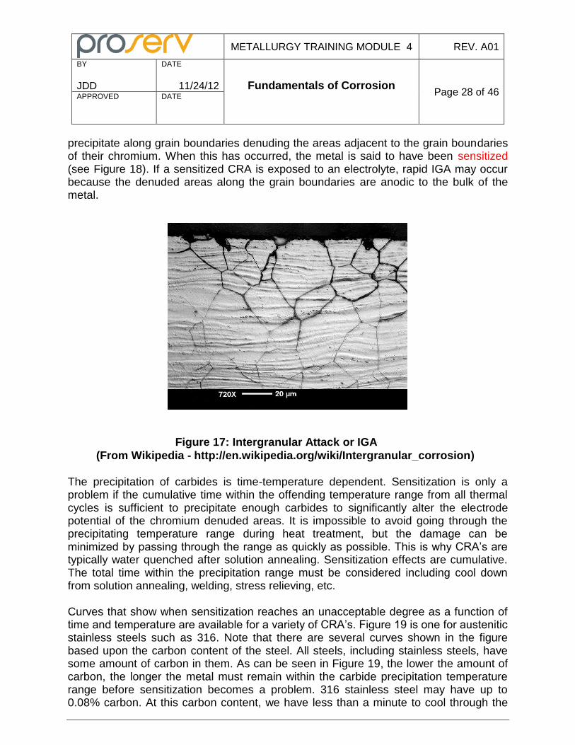
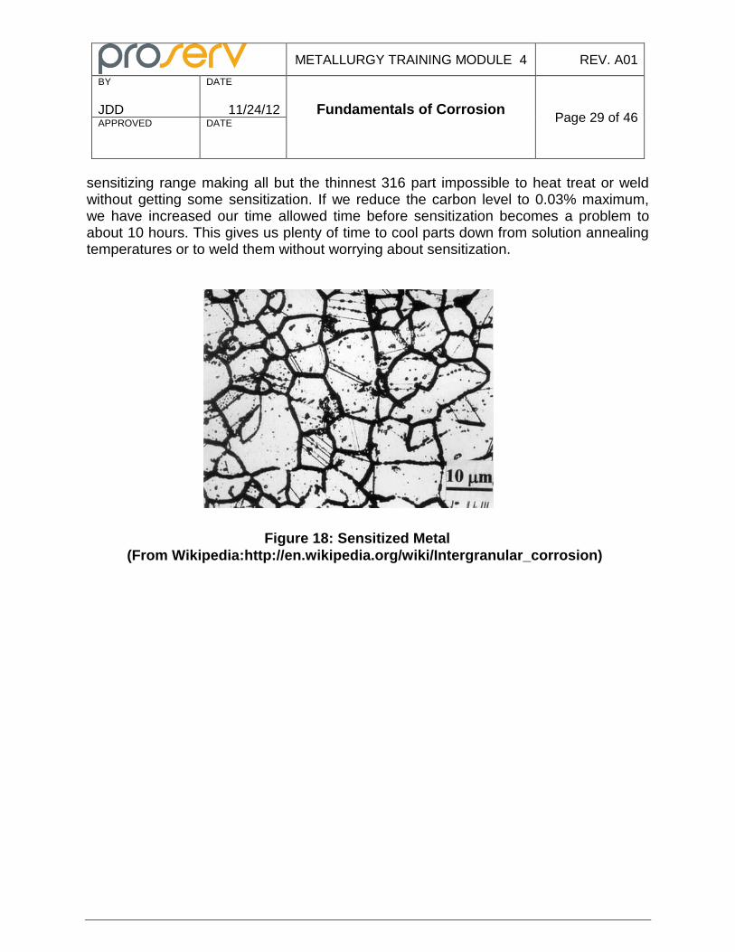
precipitate along grain boundaries denuding the areas adjacent to the grain boundaries of their chromium. When this has occurred, the metal is said to have been sensitized (see Figure 18). If a sensitized CRA is exposed to an electrolyte, rapid IGA may occur because the denuded areas along the grain boundaries are anodic to the bulk of the metal.
Figure 17: Intergranular Attack or IGA
(From Wikipedia - http://en.wikipedia.org/wiki/Intergranular_corrosion)
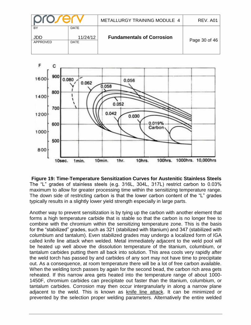
The precipitation of carbides is time-temperature dependent. Sensitization is only a problem if the cumulative time within the offending temperature range from all thermal cycles is sufficient to precipitate enough carbides to significantly alter the electrode potential of the chromium denuded areas. It is impossible to avoid going through the precipitating temperature range during heat treatment, but the damage can be minimized by passing through the range as quickly as possible. This is why CRA’s are typically water quenched after solution annealing. Sensitization effects are cumulative. The total time within the precipitation range must be considered including cool down from solution annealing, welding, stress relieving, etc. Curves that show when sensitization reaches an unacceptable degree as a function of time and temperature are available for a variety of CRA’s. Figure 19 is one for austenitic stainless steels such as 316. Note that there are several curves shown in the figure based upon the carbon content of the steel. All steels, including stainless steels, have some amount of carbon in them. As can be seen in Figure 19, the lower the amount of carbon, the longer the metal must remain within the carbide precipitation temperature range before sensitization becomes a problem. 316 stainless steel may have up to 0.08% carbon. At this carbon content, we have less than a minute to cool through the
METALLURGY TRAINING MODULE 4 REV. A01
BY
JDD
DATE
11/24/12 Fundamentals of Corrosion
Page 29 of 46 APPROVED
DATE
sensitizing range making all but the thinnest 316 part impossible to heat treat or weld without getting some sensitization. If we reduce the carbon level to 0.03% maximum, we have increased our time allowed time before sensitization becomes a problem to about 10 hours. This gives us plenty of time to cool parts down from solution annealing temperatures or to weld them without worrying about sensitization.
Figure 18: Sensitized Metal
(From Wikipedia:http://en.wikipedia.org/wiki/Intergranular_corrosion)
METALLURGY TRAINING MODULE 4 REV. A01
BY
JDD
DATE
11/24/12 Fundamentals of Corrosion
Page 30 of 46 APPROVED
DATE
Figure 19: Time-Temperature Sensitization Curves for Austenitic Stainless Steels The “L” grades of stainless steels (e.g. 316L, 304L, 317L) restrict carbon to 0.03% maximum to allow for greater processing time within the sensitizing temperature range. The down side of restricting carbon is that the lower carbon content of the “L” grades typically results in a slightly lower yield strength especially in large parts. Another way to prevent sensitization is by tying up the carbon with another element that forms a high temperature carbide that is stable so that the carbon is no longer free to combine with the chromium within the sensitizing temperature zone. This is the basis for the “stabilized” grades, such as 321 (stabilized with titanium) and 347 (stabilized with columbium and tantalum). Even stabilized grades may undergo a localized form of IGA called knife line attack when welded. Metal immediately adjacent to the weld pool will be heated up well above the dissolution temperature of the titanium, columbium, or tantalum carbides putting them all back into solution. This area cools very rapidly after the weld torch has passed by and carbides of any sort may not have time to precipitate out. As a consequence, at room temperature there will be a lot of free carbon available. When the welding torch passes by again for the second bead, the carbon rich area gets reheated. If this narrow area gets heated into the temperature range of about 1000-1450F, chromium carbides can precipitate out faster than the titanium, columbium, or tantalum carbides. Corrosion may then occur intergranularly in along a narrow plane adjacent to the weld. This is known as knife line attack. It can be minimized or prevented by the selection proper welding parameters. Alternatively the entire welded
METALLURGY TRAINING MODULE 4 REV. A01
BY
JDD
DATE
11/24/12 Fundamentals of Corrosion
Page 31 of 46 APPROVED
DATE
structure can be resolution annealed to put any chromium carbides back into solution and allow the stabilized carbides to form during subsequent cooling.
5. Selective Leaching (Dealloying)
Selective leaching, or dealloying as it is sometimes called, is the preferential removal of one or more of the alloying elements in a metal alloy through corrosion. The dezincification of brass (a copper-zinc alloy) in seawater is the most widely known example. Apparently the mechanism causing it is not just dissimilar metal galvanic corrosion on a microscale because both the copper and zinc corrode and go into solution. The zinc stays in solution, but the copper, the more noble metal, precipitates out at the surface. This results in a spongy, porous mass of copper with some copper oxides that may maintain the original shape of the part (which may appear to be undamaged), but has greatly reduced strength and ductility. Don’t be fooled by the name “naval brass”. This copper-zinc alloy, used for centuries for top side equipment on ships will rapidly undergo dealloying if immersed in seawater. Selective leaching may occur uniformly on the surface of a part, or in a localized area. The latter is often called “plug” selective leaching. Certain bronze alloys are notorious for dealloying in seawater. There are many types of bronzes and some are relatively immune to dealloying, while others dealloy rapidly. Know which ones you’re dealing with! Sometimes certain bronze alloys can be made much less susceptible to dealloying through stabilizing heat treatments. Here are some families of bronzes that may be subject to selective leaching:
Aluminum bronzes – loss of aluminum (dealuminification)
Tin bronzes – loss of tin (destannification)
Silicon bronzes – loss of silicon (desiliconification) Nickel aluminum bronzes have good resistance to dealloying if properly heat treated. The element that is preferentially removed in dealloying may change depending on the environment. The Monels™ for example, are alloys of about 60% nickel, 30%, and a few other elements depending on the specific alloy. In some acid solutions the copper will be selectively removed; and in other it’s the nickel that is removed.
6. Corrosion-Erosion
Corrosion-erosion (or erosion-corrosion if you prefer) is the removal of material through the combined effects of erosion and corrosion. The removal rate is much higher than would be expected from the simple addition of the effects of corrosion or erosion acting
METALLURGY TRAINING MODULE 4 REV. A01
BY
JDD
DATE
11/24/12 Fundamentals of Corrosion
Page 32 of 46 APPROVED
DATE
in isolation. Erosion is the loss of metal due to abrasion or impingement of a moving fluid. The fluid may or may not have entrained particulate matter in it. It can greatly accelerate corrosion by stripping away or otherwise damaging protective adhesive films (scale deposits for instance) or passive films (the oxide layer on stainless steel for example) and thus continuously expose fresh metal to the electrolyte. Sand is the biggest trouble maker in fluids coming out of wells. Sharp sand is very effective in exposing fresh meat for the grinder as it strips away protective films and removes the underlying metal through a cutting action. Alloys normally totally corrosion resistant in a given environment may suffer severe weight loss corrosion in a short period of time when their surfaces are scoured by sand moving in a high velocity fluid. Corrosion-erosion may be fairly uniform along straight runs, but is typically much more severe when the fluid is impinging directly onto a metal’s surface (at a tee or an elbow, for instance). Particulate matter need not be present in the fluid, although it certainly will make matters worse: high velocity liquids or gases by themselves can be very abrasive.
7. Corrosion Fatigue
Fatigue is the failure of a metal part under a cyclic load. The nominal load is lower than the material’s ultimate tensile strength and may be lower than its yield strength. Corrosion fatigue is failure of a metal part through a combined action of fatigue and corrosion in a specific environment. Metals that fail because of corrosion fatigue do so at a lower number of cycles or at a lower stress per cycle than the same metal failing by strictly mechanical fatigue in a benign environment such as air. Many metals are subject to corrosion fatigue in seawater. Unprotected steel parts, for example, may have a 50% or more reduction in fatigue life at a given load in seawater. Cyclic loading in service may be due to vortex induced vibration, thermal cycles, pressure pulses, etc. The number of cycles that a given part can withstand before fracture is dependent on the amplitude of the applied stress (the difference between the maximum and minimum stresses for each cycle) and the average stress. Higher amplitude requires fewer cycles to failure. As the average or mean stress becomes increasingly tensile, the smaller the amplitude has to be to maintain the same number of cycles to failure. Fatigue is a three stage process: 1. Crack Initiation - Localized strain in a metal is not completely reversible when a load is reversed or removed. The stress around a microscopic imperfection may be
METALLURGY TRAINING MODULE 4 REV. A01
BY
JDD
DATE
11/24/12 Fundamentals of Corrosion
Page 33 of 46 APPROVED
DATE
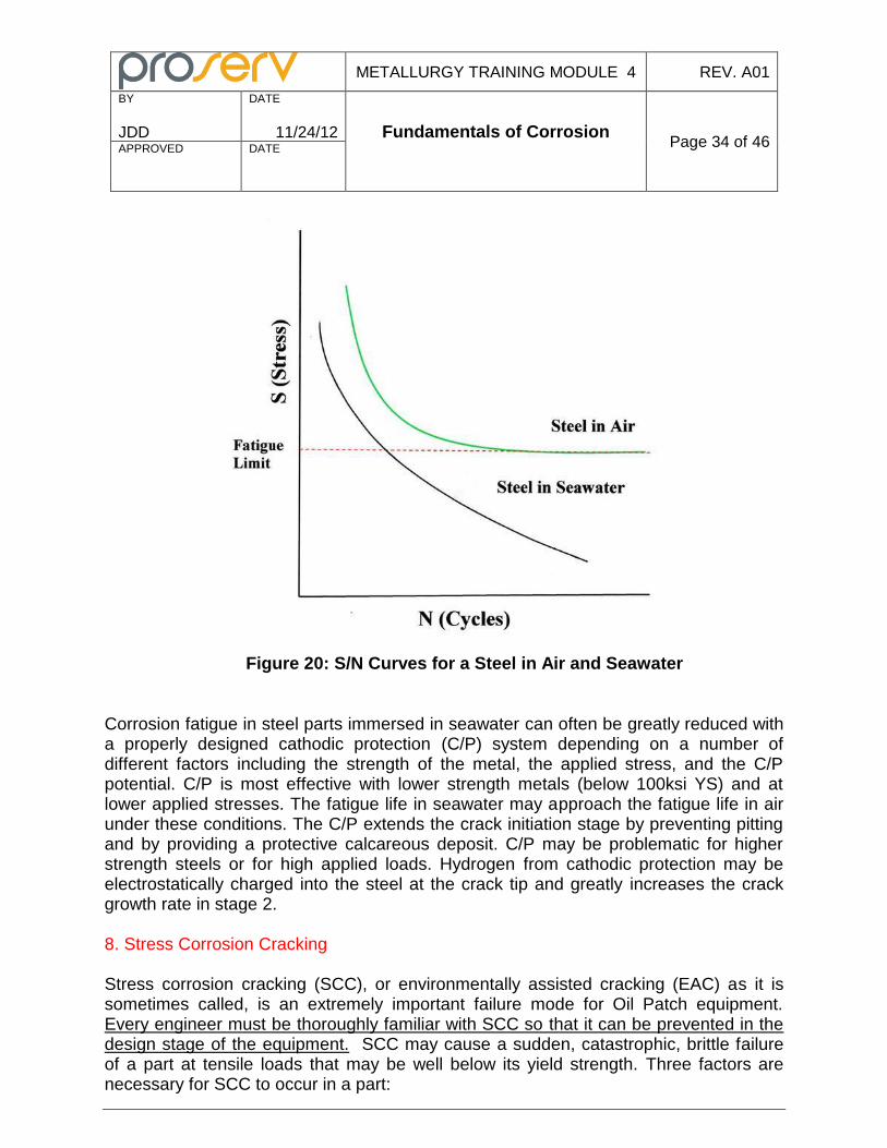
considerably higher than the overall stress that the part sees and results in permanent strain adjacent to the imperfection. As the part is repeatedly loaded, localized strains around the imperfection will accumulate until a crack forms. Typically the crack initiation stage takes up about 90% of a part’s fatigue life. This is short circuited in corrosion fatigue where pitting or other forms of corrosion facilitate crack initiation so that this stage is only about 10% of the total fatigue life. 2. Crack Propagation – The newly formed cracks grow larger in a direction normal to the maximum tensile stress as the cyclic loading causes the material adjacent to the crack tip to work harden. In corrosion fatigue, the corrosive media interacts with the material at the crack tip allowing greater growth per cycle at a given load and hence fewer cycles to failure. Similarly, the allowable load for a given fatigue life in a specific environment is reduced in corrosion fatigue. Unlike fatigue in air, stage 2 (crack propagation) in corrosion fatigue takes up about 90% of the fatigue life. This makes fracture mechanics a powerful tool in evaluating fatigue life in corrosive environments. 3. Rapid Fracture – The third stage begins when a crack has reached a critical size and the effective cross section of the part can no longer support the applied load. The behavior of a metal under a cyclic load is often represented in the form of a S/N curves (see Figure 20). This is a plot of applied stress (S) versus the number of cycles to failure (N). Ferrous materials fatigue tested in air or other benign environment have a threshold stress below which failure will not occur regardless of the number of cycles. This stress is known as the endurance or fatigue limit. Nonferrous alloys have no fatigue limit and can only be subjected to a finite number of cycles however small the applied stress. In a corrosive environment such as seawater, ferrous alloys (steels) have no fatigue limit: they will eventually fail regardless of the applied stress once a sufficient number of cycles has been reached. Great care must be exercised when utilizing published S/N curves in determining the fatigue life of equipment - make sure the curves are appropriate for your environment.
METALLURGY TRAINING MODULE 4 REV. A01
BY
JDD
DATE
11/24/12 Fundamentals of Corrosion
Page 34 of 46 APPROVED
DATE
Figure 20: S/N Curves for a Steel in Air and Seawater
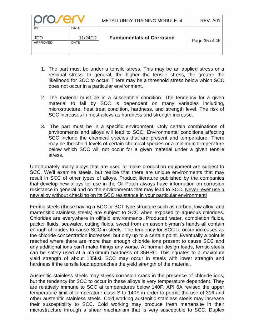
Corrosion fatigue in steel parts immersed in seawater can often be greatly reduced with a properly designed cathodic protection (C/P) system depending on a number of different factors including the strength of the metal, the applied stress, and the C/P potential. C/P is most effective with lower strength metals (below 100ksi YS) and at lower applied stresses. The fatigue life in seawater may approach the fatigue life in air under these conditions. The C/P extends the crack initiation stage by preventing pitting and by providing a protective calcareous deposit. C/P may be problematic for higher strength steels or for high applied loads. Hydrogen from cathodic protection may be electrostatically charged into the steel at the crack tip and greatly increases the crack growth rate in stage 2. 8. Stress Corrosion Cracking Stress corrosion cracking (SCC), or environmentally assisted cracking (EAC) as it is sometimes called, is an extremely important failure mode for Oil Patch equipment. Every engineer must be thoroughly familiar with SCC so that it can be prevented in the design stage of the equipment. SCC may cause a sudden, catastrophic, brittle failure of a part at tensile loads that may be well below its yield strength. Three factors are necessary for SCC to occur in a part:
METALLURGY TRAINING MODULE 4 REV. A01
BY
JDD
DATE
11/24/12 Fundamentals of Corrosion
Page 35 of 46 APPROVED
DATE
1. The part must be under a tensile stress. This may be an applied stress or a
residual stress. In general, the higher the tensile stress, the greater the likelihood for SCC to occur. There may be a threshold stress below which SCC does not occur in a particular environment.
2. The material must be in a susceptible condition. The tendency for a given
material to fail by SCC is dependent on many variables including, microstructure, heat treat condition, hardness, and strength level. The risk of SCC increases in most alloys as hardness and strength increase.
3. The part must be in a specific environment. Only certain combinations of
environments and alloys will lead to SCC. Environmental conditions affecting SCC include the chemical species that are present and temperature. There may be threshold levels of certain chemical species or a minimum temperature below which SCC will not occur for a given material under a given tensile stress.
Unfortunately many alloys that are used to make production equipment are subject to SCC. We’ll examine steels, but realize that there are unique environments that may result in SCC of other types of alloys. Product literature published by the companies that develop new alloys for use in the Oil Patch always have information on corrosion resistance in general and on the environments that may lead to SCC. Never, ever use a new alloy without checking on its SCC resistance in your particular environment! Ferritic steels (those having a BCC or BCT type structure such as carbon, low alloy, and martensitic stainless steels) are subject to SCC when exposed to aqueous chlorides. Chlorides are everywhere in oilfield environments. Produced water, completion fluids, packer fluids, seawater, cutting fluids, sweat from an assemblyman’s hands all contain enough chlorides to cause SCC in steels. The tendency for SCC to occur increases as the chloride concentration increases, but only up to a certain point. Eventually a point is reached where there are more than enough chloride ions present to cause SCC and any additional ions can’t make things any worse. At normal design loads, ferritic steels can be safely used at a maximum hardness of 35HRC. This equates to a maximum yield strength of about 135ksi. SCC may occur in steels with lower strength and hardness if the tensile load approaches the yield strength of the material. Austenitic stainless steels may stress corrosion crack in the presence of chloride ions, but the tendency for SCC to occur in these alloys is very temperature dependent. They are relatively immune to SCC at temperatures below 140F. API 6A revised the upper temperature limit of temperature class S to 140F in order to permit the use of 316 and other austenitic stainless steels. Cold working austenitic stainless steels may increase their susceptibility to SCC. Cold working may produce fresh martensite in their microstructure through a shear mechanism that is very susceptible to SCC. Duplex
METALLURGY TRAINING MODULE 4 REV. A01
BY
JDD
DATE
11/24/12 Fundamentals of Corrosion
Page 36 of 46 APPROVED
DATE
stainless steels because of their continuous ferrite matrix have better SCC resistance than the austenitics. Safe usage of these alloys is dependent on the particular alloy, the chloride concentration, and the temperature. Parts that fail by SCC often show no signs of weight loss corrosion. Depending on the alloy and environment, cracking may be Intergranular or transgranular. Failure is always brittle in nature with little associated plastic deformation except for the areas that failed in ductile overload after the SCC cracks reduced the cross section of the part beyond what could support the load. Cracks are typically branched (see Figure 21).
Figure 21: Branched Cracks Typical of SCC in an Austenitic Stainless Steel Unlike a mechanical overload or fatigue cracking, SCC may occur at multiple initiation points on the surface of a part as can be seen in Figure 21. They often begin at stress risers such as scratches or corrosion pits. Time to failure is notoriously difficult to predict. It may be measured in minutes to years depending on circumstances. Just because a susceptible alloy has lasted a few years in the field does not mean it won’t fail the next day. The time dependency for an SCC is often predicated on the time it takes for a different corrosion mechanism to create a stress riser such as a pit of a certain depth. There are three possible mechanisms for crack growth in SCC:
METALLURGY TRAINING MODULE 4 REV. A01
BY
JDD
DATE
11/24/12 Fundamentals of Corrosion
Page 37 of 46 APPROVED
DATE
Anodic Path (or Crack Tip) Dissolution - This mechanism involves accelerated corrosion along a path of higher than normal corrosion susceptibility, such as a grain boundary. The bulk of the metal surrounding the grain boundaries is passive. Stresses tend to open up the crack tip disrupting any protective film and allowing corrosion products to diffuse out and corrodents to move in to freshly exposed metal. The crack tip becomes the anode of a electrochemical cell having a very large cathode-to-anode surface area ratio.
Hydrogen Embrittlement – Hydrogen is the smallest atom and can easily diffuse into metal. It is attracted to areas under triaxial tension such as crack tips where it will collect and cause a great deal of mischief. Through a mechanism not clearly understood, it facilitates cleavage (brittle) fracture in the metal surrounding the crack tip. The crack progresses into new ductile material, becomes arrested, and then process repeats itself. Cracking may be very rapid. We will discuss hydrogen embrittlement more when we look at Hydrogen Damage.
Film Induced Cleavage – A ductile material may be protected by a passive film that is relatively brittle. A crack may easily propagate through this brittle layer then become arrested as it enters the ductile material underneath. If the brittle film forms through corrosion, then the area inside the crack will repassivate forming a new brittle layer and the process repeat itself. This particular mechanism of SCC is most often associated with the deposits that form on alloys that have undergone selective leaching.
Depending upon the particular mechanism that is involved, cathodic protection may mitigate or aggravate SCC. If the anodic path dissolution mechanism is the one in play, C/P may prevent the SCC from occurring. If; however; hydrogen embrittlement is the mechanism, then C/P may contribute to SCC failure. Hydrogen ions are electrostactically charged into the metal at the cathode of an electrochemical cell. Hydrogen will then collect at the crack tip. Many engineers have succumbed to the siren’s song that high strength is better. It may allow you to minimize the size and weight of part. In the case of fasteners it may allow you reduce the size or number of fasteners. It may allow for increased load capacity or pressure rating. Designing a part using yield strength as the only criteria is fraught with danger. The higher the yield strength, the lower the toughness and ductility, the harder it will be to process the metal, the harder it will be to weld, but most importantly the more susceptible it will become to SCC. Always use the lowest strength material you can get away with because it will be the most forgiving material. Better a big, robust part at low strength, than a compact, high strength part prone to cracking!
METALLURGY TRAINING MODULE 4 REV. A01
BY
JDD
DATE
11/24/12 Fundamentals of Corrosion
Page 38 of 46 APPROVED
DATE
Fasteners are especially prone to SCC because they are highly loaded and have built-in stress risers in the form of thread roots. Cap screws are among the worst. Not only are they threaded, but the juncture where the head joins the shank is very highly stressed. Both are excellent stress risers for initiating SCC. Cap screws are often a commercial part in an oil field equipment assembly. ASTM A574 is one of the most common standards used for ordering steel cap screws. Never ever use them on ARGUS Subsea equipment! I’ll repeat that. Never, ever use them on ARGUS Subsea equipment! They have a yield strength well over 150ksi and are guaranteed to eventually fail by SCC in oil field environments. People use them because they are commercially available. It’s a big mistake. They can be used if they are tempered back to 35HRC. Wellhead equipment can be exposed to a myriad of fluids: environmental (such as seawater), produced fluids, completion and packer fluids, and injected fluids. There are hundreds of different chemicals that are routinely injected into wells for various reasons. All must be carefully scrutinized for compatibility with the materials of construction to insure that SCC does not occur. 9. Liquid and Solid Metal Embrittlement Liquid metal embrittlement (LME) and solid metal embrittlement (SME) occur when a normally ductile metal is exposed to a low melting temperature metal at an elevated temperature for a period of time and becomes embrittled when the atoms of the low melting temperature metal diffuse into the other metal’s grain boundaries thus lowering the cohesive force between the grains. LME occurs at temperatures above the melting point of the embrittling metal, while SME occurs below. A tensile stress is necessary for cracking to occur. There are many combinations of metal couples that may undergo LME and SME. The ones of most concern to us involve cadmium, zinc, and mercury as the embrittling metals Mercury is occasionally found in some gas wells. It can embrittle steels, nickel base alloys, and aluminum alloys. It is generally not a problem for wellhead equipment because the amount of mercury is typically very low and it is entrained in a production fluid so not much contacts the surface of the wellhead equipment. It is a serious problem for downstream heat exchangers that frequently use aluminum tubes. Here the mercury may become concentrated and cause extensive cracking of the aluminum tubes. Cadmium and zinc may cause SME of steels exposed to temperatures above 350F (API 6A temperature rating X). Both cadmium and zinc are often electroplated on steel fasteners in order to provide corrosion resistance. They form a sacrificial coating that cathodically protects the substrate. Zinc is also used in the form of galvanizing on many other steel parts. Never use zinc or cadmium plated parts or galvanized parts at service
METALLURGY TRAINING MODULE 4 REV. A01
BY
JDD
DATE
11/24/12 Fundamentals of Corrosion
Page 39 of 46 APPROVED
DATE
temperatures over 350F! At higher temperatures use black bolts (uncoated) or phosphate coated fasteners. Do not allow galvanized chains to come into contact with steel parts! The zinc that makes up the galvanized coating is relatively soft that can easily be abraded onto the surface of a harder, steel part. This may lead to LME or SME if the part later undergoes a high temperature thermal cycle (heat treatment, welding, induction bending, stress relieving, etc. Galvanized chains may not be found in your shop, but be careful of truckers who use chains to secure their loads – this is particularly a problem with pipes! 10. Hydrogen Damage Hydrogen damage is an umbrella term used for a group of processes by which hydrogen can degrade a metal. We’ll look only at those that may be encountered in the Oil Patch where there is an external source of hydrogen. These include hydrogen blistering, hydrogen attack, hydride formation, and hydrogen embrittlement. There are many sources of hydrogen or hydrogen ions in the Oil Patch. Hydrogen is a byproduct of the corrosion processes in aqueous solutions. It is present in acids used to acidize wells. It is a byproduct of cathodic protection. Parts may be exposed to hydrogen during manufacture if they are pickled, welded, or electroplated. Hydrogen blistering may occur in low strength steels when hydrogen ions are reduced and adsorbed onto the steels surface as monatomic hydrogen. These hydrogen atoms then may diffuse into the steel where they will collect at microscopic voids or other “traps” like the interface with nonmetallic inclusions. Here they will combine to hydrogen gas. The gas molecule H2 is too big to diffuse out of a void so pressure begins to rise as the amount of gas increases. If the void is just below the surface, the internal hydrogen gas pressure in a void may cause a bulge or a blister in the surface. Hydrogen attack of susceptible steels is most often seen in refineries and chemical plants that use high pressure hydrogen in their processing. It occurs at temperatures over 400F and is the result of hydrogen atoms diffusing into the steel and combining with carbon to form methane gas in the reaction 4H + Fe3C → CH4 + 3Fe This typically occurs at voids, laminations, or other discontinuities Methane forming at the very surface will be lost to the surrounding environment leaving a decarburized zone on the surface of the part. Methane produced subsurface is too large to diffuse through the steel and the pressure will build up as more and more methane forms. If this occurs near the surface a blister may form. Cracking may occur in deeper locations. Carbon steels are most susceptible to hydrogen attack. Alloying elements such as chromium and molybdenum in low alloy steels form stable carbides that tie-up the carbon making the carbon unavailable to react with hydrogen. As a consequence low alloy steels will perform better than carbon steels. Nelson curves show the safe operating limits in terms of temperature and hydrogen partial pressure for different steel alloys.
METALLURGY TRAINING MODULE 4 REV. A01
BY
JDD
DATE
11/24/12 Fundamentals of Corrosion
Page 40 of 46 APPROVED
DATE
Titanium, magnesium, tantalum, columbium, vanadium, and zirconium and some of their alloys are subject to hydride embrittlement. These can combine with hydrogen to form brittle hydrides. At low hydrogen concentrations (below the solubility limit) stress assisted hydride formation causes embrittlement. Here hydrides form a brittle layer along the length of the crack and at the crack tip. Local stresses at the crack tip fracture this brittle layer exposing fresh metal and the process repeats itself. The process is enhanced under conditions of slow strain. At hydrogen concentrations above the solubility limit, severe embrittlement may occur as brittle hydrides precipitate out on slip planes or other discontinuities. Increased strain rates, lower temperatures, and the presence of stress risers in the material all lead to more severe embrittlement. We’ll focus on titanium because the other metals are not often used in the Oil Patch. Titanium is sometimes used especially for downhole applications because of its excellent general weight loss corrosion resistance, its low modulus, and especially for its light weight. Cases of hydride formation in titanium are rare in the Oil Patch, but they can occur. The solubility of hydrogen in commercially pure titanium (alpha alloys) and in alpha-beta alloys is low (50-300ppm). In beta alloys the solubility is about 4,000ppm. Thus beta alloys can much tolerate more hydrogen before becoming embrittled: hydrides will precipitate out once the hydrogen content exceeds the solubility limit. The passive oxide layer that makes titanium corrosion resistant is an effective barrier to hydrogen diffusion. It is important therefore to use titanium only where passivity is maintained and to prevent mechanical damage to the protective film. Temperatures above 80
oC are generally necessary to cause significant hydrogen entry into the metal.
Diffusion is very sluggish at lower temperatures. Hydride embrittlement of titanium may occur in seawater may occur under unusual circumstances and is dependent on the specific alloy involved. Problems may occur if:
Titanium is coupled to a less noble metal
Cathodic protection system potential is < 0.85v SCE
Parts are actively strained
The pH is less than < 3 or > 12
The temperature is above 80oC
In general it is good practice to electrically isolate the titanium from less noble metals and from the cathodic protection system when using it subsea. Hydrogen embrittlement is the loss of ductility and toughness that occurs in a susceptible metal when it interacts with hydrogen. Under a tensile load, it may lead to a rapid and catastrophic failure. It may be considered a specialized case of stress corrosion cracking where the cracking occurs in an environment containing hydrogen. There are many theories about what causes hydrogen embrittlement and there may be several different mechanisms involved. A few of the leading candidates are:
METALLURGY TRAINING MODULE 4 REV. A01
BY
JDD
DATE
11/24/12 Fundamentals of Corrosion
Page 41 of 46 APPROVED
DATE
Monatomic hydrogen diffuses into the metal and collects at discontinuities such as voids, inclusions, porosity, etc. where the atoms combine to make hydrogen gas. The hydrogen gas molecule is too big to diffuse out. Pressure then builds up and leads to cracking.
Hydrogen entry into the metal at the crack tip is facilitated by triaxial tension. Here it reduces the interatomic cohesive forces of the base metal.
Hydrogen at the crack tip interferes with the redistribution of stresses by plastic deformation.
Regardless of what actually is going on at an atomic level, the effects of hydrogen embrittlement are easily seen when a part fractures in two! Hydrogen is prevalent in Oil Patch environments. It is a byproduct of corrosion processes; it is generated at the surface of subsea equipment under cathodic protection, it is a byproduct of electroplating processes and pickling operations. Hydrogen sulfide (H2S) is gas often found in oil and gas wells that can be a source of hydrogen. Recall that monatomic hydrogen combines to form hydrogen gas on the surface of a cathode and that this gas is then lost to the atmosphere. This reduces the amount of hydrogen diffusing into the metal. Certain impurities present on the surface of the metal such as sulfur, arsenic, phosphorous, or the cyanide ion (CN
-), may interfere with the formation of the hydrogen
gas molecule thus permitting much more monatomic hydrogen to diffuse into the metal. The presence of H2S increases the corrosion rate of steel thus increasing the amount of hydrogen being generated. Like the sulfur, arsenic, and the other impurities just mentioned, H2S poisons the formation of hydrogen gas thus allowing more hydrogen atoms to diffuse into the metal and wreak havoc. Many alloys commonly used in the Oil Patch are susceptible to hydrogen embrittlement depending primarily on their heat treat condition, strength level, magnitude of tensile stress, and the specific environment. The internal discontinuities, defects, strain fields, precipitates, etc. that strengthen a metal provide the sites for hydrogen to interact with. Thus the higher the strength of a metal, the more susceptible it becomes. A heat treatment that provides a microstructure with rounded constituents is less susceptible than one with sharp, angular constituents like martensite. Environmental factors are important. Obviously the amount of hydrogen available is important, but other factors such as the presence of chlorides, temperature, pH can also influence the tendency for hydrogen embrittlement to occur. In general the higher the tensile load a susceptible metal part is under, the more likely it will fail. Temperature has a mixed effect. In the case of most steels, the worst case is at room temperature. The diffusion rate of hydrogen is too slow at lower temperatures to allow much hydrogen to enter the steel. At higher temperatures hydrogen will outgas from the part.
METALLURGY TRAINING MODULE 4 REV. A01
BY
JDD
DATE
11/24/12 Fundamentals of Corrosion
Page 42 of 46 APPROVED
DATE
The permeability of hydrogen in metals with a ferritic microstructure (body centered cubic) is high, but these materials have a low capacity for absorbing hydrogen. Conversely, hydrogen has poor diffusivity in austenitic materials (face centered cubic), but these materials can absorb much more hydrogen in their microstructures than BCC. Austenitic materials as a consequence tend to have better hydrogen embrittlement resistance than those with BCC structures. Hydrogen induced stress cracking or HISC is a very important type of hydrogen embrittlement. It occurs on susceptible metal parts that are subsea and under cathodic protection. The principle of cathodic protection is that the part to be protected is made the cathode of an electrochemical cell. As the anode (typically aluminum) corrodes, it provides free electrons that totally suppress corrosion at the cathode. The cathode becomes negatively charged as a result of the influx of free electrons. Hydrogen ions in the electrolyte (the seawater) are positively charged and thus are attracted to the cathode. The cathode is thus electrostatically charged with hydrogen atoms – it’s not just a diffusion process. Hydrogen embrittlement may then occur. High strength carbon, low, allow, and martensitic stainless steels are all subject to HISC if over 35HRC. Duplex stainless steels are especially prone to HISC and require careful processing and special design criteria when used under cathodic protection. Guidelines can be found in DNV RP F112 Design of Duplex Stainless Steel Subsea Equipment Exposed to Cathodic Protection. A thorough understanding of HISC is vitally important to every subsea engineer. Material selection is an important aspect of HISC prevention, but equally important is the design of the equipment. HISC is important enough that there will be a separate training module just on this topic. H2S embrittlement, also called sulfide stress cracking or SSC, is another very important type of hydrogen embrittlement. As previously mentioned, H2S is very common in both oil and gas wells. It acts as a poison that keeps monatomic hydrogen from combining to form hydrogen gas thus frees up more atomic hydrogen for diffusion into the base metal. The criteria for safe usage of materials are going to be more stringent or restrictive than in other hydrogen environments because of this. For example 35HRC maximum renders low alloy steels relatively immune to HISC, but 22HRC maximum is required in H2S. Hydrogen sulfide is a very deadly gas to both people and metals. NACE MR0175/ISO 15156 is the international standard most often imposed upon metals used in production equipment for fields containing enough H2S to be a problem in terms of embrittlement. This threshold limit of H2S is set by NACE at a partial pressure of 0.05psi – it doesn’t take much H2S to cause problems. Oil and gas field having 0.05 psi or more partial of H2S are said to be sour. We’ll look at this important standard in detail in its own training module and in the training module on Wellhead Corrosion. In addition to the classical SSC already described, NACE MR 0175 recognizes several other distinct forms of SSC based largely on the crack morphology or the location of cracking. These include:
METALLURGY TRAINING MODULE 4 REV. A01
BY
JDD
DATE
11/24/12 Fundamentals of Corrosion
Page 43 of 46 APPROVED
DATE
Hydrogen Induced Cracking (HIC) – This mode consists of cracks that occur along certain planes in the microstructure in carbon and low alloy steels as monatomic hydrogen diffuses into the metal and collects at discontinuities. Here they combine to form hydrogen gas which is too large to diffuse out. Pressure builds and eventually results in cracks. HIC is most often associated with rolled products that have banded microstructures or laminations. No external stress is necessary for HIC to occur.
Soft Zone Cracking (SZC) – The heat affected zone (HAZ) of a weld has been heated to a high temperature during welding and this may lower its yield strength. It becomes a weak link in the load path in the part that may plastically deform at loads under the specified minimum yield. This plasticity makes it more susceptible to SSC than the parent metal away from the HAZ.
Stress Oriented Hydrogen Induced Cracking (SOHIC) – This occurs mainly in low strength ferritic pipe and pressure vessel materials. Staggered, small cracks form perpendicular to the principle stress and link up with pre-existing HIC cracks to form a ladder-like array of cracks.
Stepwise Cracking (SWC) – This involves the linking of HIC cracks by cracks growing perpendicular from one end of a HIC crack to the beginning of another on a different plane producing a staircase-like appearance. It is most often associated with low strength, rolled products such as plate.
Microbiologically Induced Corrosion (MIC)
The corrosion of ferrous alloys in water or soils that are poor in oxygen can be accelerated by the presence of certain types of bacteria. Metal parts such as oil well casings, water well pipe, buried pipelines, heat exchangers, cooling towers, etc. often create the perfect environment for these types of bacteria to flourish. Anaerobic bacteria are the most problematic. Anaerobic means that this group of bacteria can only live in an environment with little or no oxygen present. Anaerobic bacteria that may cause corrosion problems for steel components include sulfate reducing bacteria (SRB), sulfur/sulfide-oxidizing bacteria, iron/manganese oxidizing bacteria, and methane producing bacteria. SRB cause the most damage. The bacteria of course don’t attack the metal directly (they don’t consume the metal as part of their diet!), but the byproducts of their metabolism may accelerate corrosion of the underlying metal through several different mechanisms. SRB, under some circumstances, can cause an oil field with no H2S present initially to become sour later on its life through the following proposed reactions:
METALLURGY TRAINING MODULE 4 REV. A01
BY
JDD
DATE
11/24/12 Fundamentals of Corrosion
Page 44 of 46 APPROVED
DATE
Anode: 4Fe → 4Fe
+2 + 8e
-
Cathode: 8H2O + 8e
- → 8H + 8OH
-
8H + Na2SO4 → 4H2O + Na2S Na2S + 2H2CO3 →2NaHCO3 + H2S Overall Reaction: 4Fe + 2H2O +Na2SO4 + 2H2CO3 → 3Fe (OH)2 + FeS + 2NaHCO3 SRB thus reduce inorganic sulfates to sulfides and in doing so consume large amounts of hydrogen (depolarizing cathode areas). A large number of electrons are consumed at the cathode so the anode must corrode more quickly to make up the difference. Note that H2S is a by-product of one of the cathode reactions. SRB may cause a formation with no H2S to become sour over a period of time particularly if water injection is used to enhance production. Most customers always order equipment meeting NACE requirements even if there is no starting H2S in the formation if water injection is employed to maintain formation pressure. Injected water is a likely source for introducing SRB into the formation, along with the nutrients they thrive on. Other types of anaerobic bacteria can cause corrosion because the byproducts of their metabolism are acidic. Aerobic bacteria (those that live in oxygen rich environments) can indirectly cause corrosion by forming mats of slime that adhere to the surface of the metal. This excludes the underlying metal from oxygen so an oxygen concentration cell is set up.
Corrosion by Acid Gases Acid gases, as the name suggests, are those gases that form acids when they are dissolved in water. The two of most concern to the Oil Patch are carbon dioxide and hydrogen sulfide. We’ve already discussed how H2S can embrittle steel, but its presence can also accelerate general weight loss corrosion and pitting. The acid gases tend to form relatively weak acids. Any lowering of the pH, however, tends to depolarize the cathode and increase the corrosion rate at the anode. The additional H
+ ions
provided by even a weak acid will consume electrons at the cathode that must be
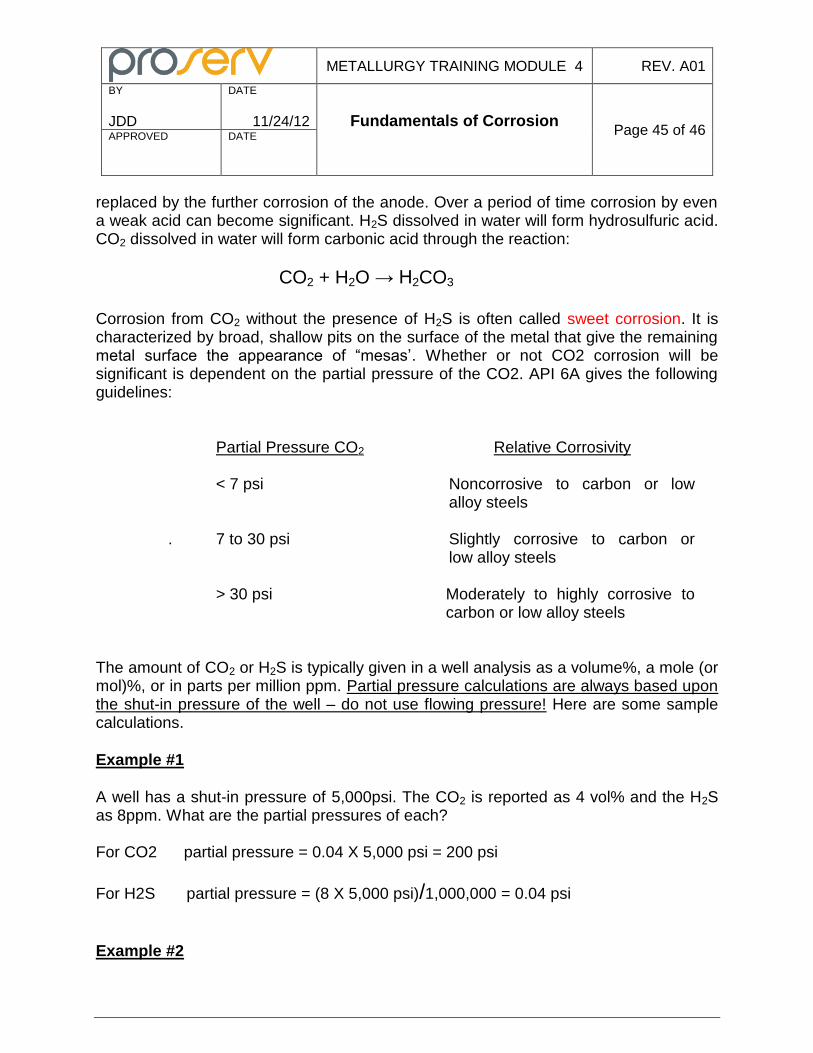
METALLURGY TRAINING MODULE 4 REV. A01
BY
JDD
DATE
11/24/12 Fundamentals of Corrosion
Page 45 of 46 APPROVED
DATE
replaced by the further corrosion of the anode. Over a period of time corrosion by even a weak acid can become significant. H2S dissolved in water will form hydrosulfuric acid. CO2 dissolved in water will form carbonic acid through the reaction:
CO2 + H2O → H2CO3
Corrosion from CO2 without the presence of H2S is often called sweet corrosion. It is characterized by broad, shallow pits on the surface of the metal that give the remaining metal surface the appearance of “mesas’. Whether or not CO2 corrosion will be significant is dependent on the partial pressure of the CO2. API 6A gives the following guidelines:
Partial Pressure CO2 Relative Corrosivity < 7 psi Noncorrosive to carbon or low
alloy steels . 7 to 30 psi Slightly corrosive to carbon or
low alloy steels > 30 psi Moderately to highly corrosive to
carbon or low alloy steels The amount of CO2 or H2S is typically given in a well analysis as a volume%, a mole (or mol)%, or in parts per million ppm. Partial pressure calculations are always based upon the shut-in pressure of the well – do not use flowing pressure! Here are some sample calculations.
Example #1
A well has a shut-in pressure of 5,000psi. The CO2 is reported as 4 vol% and the H2S as 8ppm. What are the partial pressures of each? For CO2 partial pressure = 0.04 X 5,000 psi = 200 psi
For H2S partial pressure = (8 X 5,000 psi)/1,000,000 = 0.04 psi
Example #2
METALLURGY TRAINING MODULE 4 REV. A01
BY
JDD
DATE
11/24/12 Fundamentals of Corrosion
Page 46 of 46 APPROVED
DATE
A well has a shut-in pressure of 10,000 psi. The CO2 is reported as 1.5 mol% and the H2S as 5ppm. What is the partial pressure of each? For CO2 partial pressure = 0.015 X 10,000 psi = 150 psi For H2S partial pressure = (5 X 10,000 psi)/1,000,000 = 0.05 psi The API guidelines for CO2 corrosion are just that: guidelines and not gospel. There are many other factors that mitigate or aggravate CO2 corrosion besides partial pressure. We’ll examine the influence of these other factors in the training module on Wellhead Corrosion. Dry CO2 and dry H2S won’t cause corrosion or embrittlement: water must be present for carrion to occur.