Embed Size (px)
Citation preview
N A T u R A L RESOURCE
FUNDAMENTALS OF BLASTING AND RECLAMATION BLASTING WORKSHOP
June 28, 29, and 30, 1994

DISCLAIMER
This report has not been edited or reviewed for conformity with Division of Geology and Earth Resources standards and nomenclature and should not be cited.
CONTENTS
i PREFACE
1 Chapter 1: GLOSSARY OF TERMS
7 Chapter 2: PROPERTIES OF EXPLOSIVES
11 Chapter 3: TYPES OF EXPLOSIVES
23 Chapter 4: THEORY OF EXPLOSIVES
27 Chapter 5: UNIFORM ROCK CLASSIFICATION SYSTEM
31 Chapter 6: BLASTING CALCULATIONS
35 Chapter 7: RULES OF THUMB FOR BLASTING
39 Chapter 8: DELAY SYSTEM
45 Chapter 9: INITIATION SYSTEMS
53 Chapter 10: VIBRATIONS FROM BLASTING
57 Chapter 11: BLASTING PLANS AND LOGS
Appendix "A" RECLAMATION ARTICLES

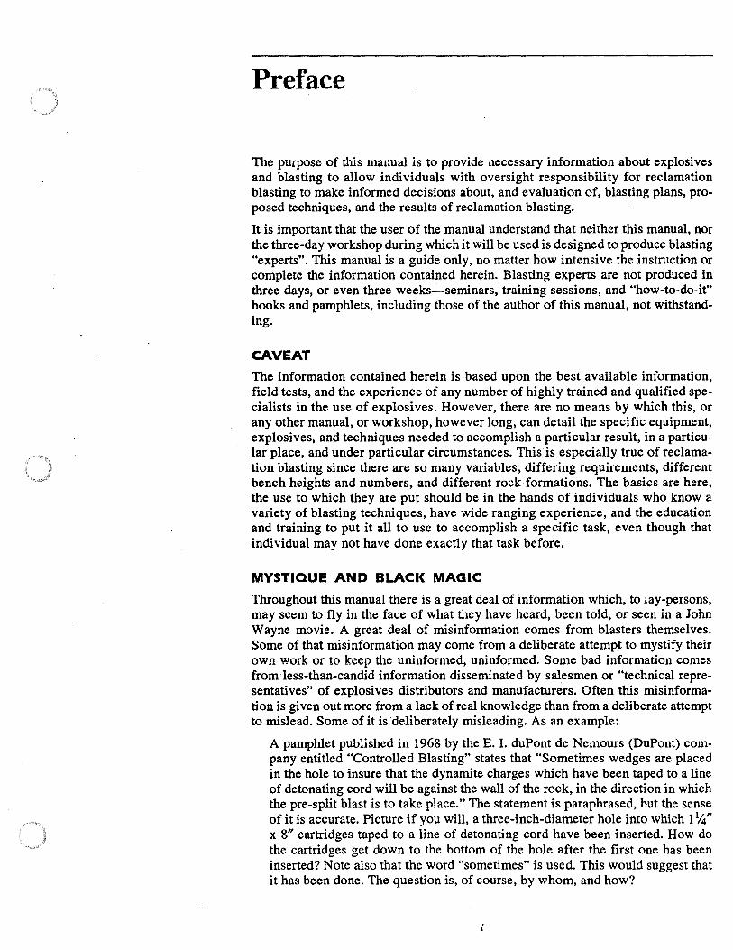
Preface
The purpose of this manual is to provide necessary information about explosives and blasting to allow individuals with oversight responsibility for reclamation blasting to make informed decisions about, and evaluation of, blasting plans, proposed techniques, and the results of reclamation blasting.
It is important that the user of the manual understand that neither this manual, nor the three-day workshop during which it will be used is designed to produce blasting "experts". This manual is a guide only, no matter how intensive the instruction or complete the information contained herein. Blasting experts are not produced in three days, or even three weeks-seminars, training sessions, and "how-to-do-it" books and pamphlets, including those of the author of this manual, not withstanding.
CAVEAT
The information contained herein is based upon the best available information, field tests, and the experience of any number of highly trained and qualified specialists in the use of explosives. However, there are no means by which this, or any other manual, or workshop, however long, can detail the specific equipment, explosives, and techniques needed to accomplish a particular result, in a particular place, and under particular circumstances. This is especially true of reclamation blasting since there are so many variables, differing requirements, different bench heights and numbers, and different rock formations. The basics are here, the use to which they are put should be in the hands of individuals who know a variety of blasting techniques, have wide ranging experience, and the education and training to put it all to use to accomplish a specific task, even though that individual may not have done exactly that task before.
MYSTIQUE AND BLACK MAGIC
Throughout this manual there is a great deal of information which, to lay-persons, may seem to fly in the face of what they have heard, been told, or seen in a John Wayne movie. A great deal of misinformation comes from blasters themselves. Some of that misinformation may come from a deliberate attempt to mystify their own work or to keep the uninformed, uninformed. Some bad information comes from less-than-candid information disseminated by salesmen or "technical representatives" of explosives distributors and manufacturers. Often this misinformation is given out more from a lack of real knowledge than from a deliberate attempt to mislead. Some of it is deliberately misleading. As an example:
A pamphlet published in 1968 by the E. I. duPont de Nemours (DuPont) company entitled "Controlled Blasting" states that "Sometimes wedges are placed in the hole to insure that the dynamite charges which have been taped to a line of detonating cord will be against the wall of the rock, in the direction in which the pre-split blast is to take place." The statement is paraphrased, but the sense of it is accurate. Picture if you will, a three-inch-diameter hole into which 11/4" x 8" cartridges taped to a line of detonating cord have been inserted. How do the cartridges get down to the bottom of the hole after the first one has been inserted? Note also that the word "sometimes'' is used. This would suggest that it has been done. The question is, of course, by whom, and how?
Another example is from an older ( circa 1968) version of the ubiquitous 0 Blaster' s Handbook". also from DuPont. This states that when. breaking boulders with what is called a 0 mud cap". dynamite is placed on the rock, and then covered with about 6H to 8H of mud so that there will be 25 percent more effect going down. It take no genius to figure out that where there is a product that will generate abou~ 675,000 foot pounds of pressure at about 14,000 feet per second, the addition of 6H to 8" of mud will not apply 25 percent more pressure downward. Fortunately, that edition of the handbook is now out of date, but unfortunately, it is to be found on a great many bookshelves and is immediately taken down for reference any time blasting is the subject of discussion.
Examples of 0 black magic" abound in the blasting world. Let us dispel some of that magic now.
• Detonating cord will not cut down trees, cut reinforcing rod, or break the locks on prison cell doors.
• There is no known instance where a hand-held radio has caused premature detonation of an electric blasting cap.
• The odds against an electric blasting cap misfiring from an inherent failure are about 1,000,000: 1.
• There is no relationship between the diameter of a borehole and the size of the stemming that should be used.
• Stemming does not hold gases in a borehole.
• The percentage rating of commercial explosives has no real relationship to how much work the explosive will do-it's detonation pressure, or how much nitroglycerine is in the material. In fact, it really doesn't mean anything.
• There is nothing safe about "safety fuse".
• It is not 0 gases" that break rock. Nor is the rock "pulled" from the face.
• Sub-drill is not a function of the burden. It is, in fact, a function of the largest dimension in the blast geometry, which in most cases is, or should be, the spacing.
The black magic and mystique surrounding the whole field of explosives use is gradually being eroded. Blasting is now, finally, being looked at more and more as a science. Not a hard science, but a science none-the-less.
BLASTING AS SCIENCE
There is much yet to be learned about explosives and reactions to explosions. There are dozens of questions that can be asked, and indeed, should be asked. What is the role of stemming? How much more breakage occurs as powder factors are increased? How much delay timing per foot of burden is required for optimum fragmentation, and minimal displacement? Is there a means of mathematically determining optimum spacings and burdens based upon some relationship between the characteristics of a specific explosive and the characteristics of a specific rock formation?
The questions will go on and on. Unfortunately, there is an almost unbridgeable gap between those who do research into blast effects and those who need to know and understand that research because they use explosives in their daily work. Some laws of physics-immutable, fixed, unquestioned by anyone with some knowledge of science-are not even considered by blasters in the field. "Back break" i~ <I
perfect example. Back break can be, and often is, a rather serious problem. ~ J often it is accepted, cursed, damned, and lived with. Yet the root cause is often f matter of 0 opposite and equal reaction". The mass of rock forward of the final row of holes does not move sufficiently to allow complete movement of the rock in the
ii
final row of holes. If the rock cannot go forward, much of the energy will go to the rear and up, causing back break and fly rock. Solution? Reduce the number of rows, increase the timing between the next to last and the last row, and reduce the burden by a foot or so.
Reduction of vibration is another example of "opposite and equal reaction". The greater the sub-drill, the greater the vibration that will result. Obviously! Sub-drill has, to all intents and purposes, no relief. The burden is infinite. The vibration is omnidirectional with no path of relief, the result of which is added particle displacement, which is of course, vibration. Another example that should be part of the knowledge of every blaster is that in delayed blasts, square patterns produce greater vibration, pound for pound, than do rectangular patterns, provided that there is hole for hole and row for row delay.
OPINIONS
What follows in this manual is NOT a matter of opinion, this author's or anyone else's. Everything here has been checked and double checked so that no one can point at any specific statement and say with any accuracy, "That is a matter of opinion", or worse yet, "That's your opinion". Wherever and whenever an opinion is required, or stated, there will be a preface such as, "It is .......... ' s opinion that ..... " Or, "It is my opinion that ..... " In these cases, take the opinion for exactly what it is-an opinion, not to be confused with fact, or even, necessarily, rational thought.
It is this author's opinion that opinions should be relegated to horse racing, poker, politics, and religion. In these instances, opinions are all that really matter, and the facts are what we want them to be.
iii

iv
Chapter 1: Glossary of Terms
All disciplines have their own terminology. Some terminology, in some disciplines, is so esoteric that it becomes almost unintelligible. And in some instances, not just almost, either. Blasting is no exception, though there are few terms which are not self-explanatory. It is also well to note that in some parts of the U.S. a term means one thing, and in other parts, the same term means something rather different. In the eastern part of the U.S. and in Hawaii, where I started into blasting, "rip-rap" meant, and probably still means, big boulders, three, to four feet in one or more dimensions. Here in the Northwest "rip-rap" means somewhere around 18" to 24", or thereabouts, depending upon the requirements. A '1ack-hammer" meant to me a hammer that breaks up pavement. In other places it means a hand held rock drill. Sometimes it can mean either. This glossary then is to insure that we all speak the same language, the same "lingo". Besides, some of the terms are great to throw out just to let others know that we know.
air blast (over pressure) - That portion of the shock wave generated from an explosion that is directly transmitted through the air.
air gap (air deck) - A method of blasting utilizing "decoupling", where a charge is placed in a borehole, but the entire hole is not loaded. The top portion of the hole is tightly stemmed, leaving a gap of air between the top of the charge and the bottom of the plug .used to hold the stemming in the borehole. It can be used in boulder breaking; to avoid throw from the top, or to reduce explosives where there is a relieved burden.
AN-FO - A chemical compound consisting of ammonium-nitrate prills (prills being small roundish beads, usually white, unless dyed to insure proper mix) and fuel oil (generally diesel fuel, though any carbonaceous material can be, and sometimes is, used). The mix is 94 percent AN to 6 percent fuel oil. The resultant mix is classified as a blasting agent. ·
axial priming - A technique of priming and initiating AN-FO charges in a borehole along the long axis of the column of AN-FO, as opposed to end priming, where the initiating charge is placed at the bottom of the borehole. Used primarily to increase detonation velocity of AN-FO in small diameter holes (4" or less). The priming column need not be centered, but should be sufficient to make up about 25 percent of the total volume of expl,osives in the borehole, for example, loading 2" x 16"-sticks of high explosive into a 3.5"-diameter hole and filling the annular space with AN-FO. Velocity of detonation (VOD) of AN-FO in a 3.5" hole is about 10,000-11,000 feet per second. If the hole is axially primed as noted, the VOD will increase to the VOD of the priming explosive.
back break - Rock broken beyond the limits of the last row of holes in a blast pattern. Often the cause of oversize material in subsequent blasts. There is an old blasting axiom that applies here, "What you see is what you get". If there is back break, the boulders visible in the back wall will probably wind up in the muck pile of the next blast.
bench - The horizontal ledge in a quarry or mine face, along which holes are drilled vertically and parallel to the face.
blasting agent - Any material or mixture consisting of a combustible and an oxidizer, which is intended for blasting use, and not otherwise classified as an explosive; provided that the finished product, as mixed and packaged, cannot be detonated by a #8 test blasting cap. (#8 test cap not to be confused with a #8 delay blasting cap. Most commercial blasting caps are rated as #6 caps.)
boot-leg (rifling, shotgunning, sometimes "blow out") - Where the blast fails to cause rock breakage, and stemming is blown out of the borehole. Caused by insufficient explosives for the amount of burden or incomplete detonation of the explosive charge.
borehole - A hole drilled into rock, or other hard material, for the placement of explosives.
1
2 BLASTING MANUAL
bridging - Where a column of explosives in a borehole is broken either by improper placement, or, as in the case of poured explosives such as a slurry or emulsion, some foreign matter has blocked the borehole. Literally, a bridge across the borehole.
burden - The distance from a row of holes to the nearest free face, or the next adjace. row of holes.
cap sensitive - The ability of an explosive to be detonated by a #8 test blasting cap. Cap sensitive explosives are often referred to as high explosives though some non-cap sensitive explosives, when properly initiated, will detonate at high velocity.
characteristic impedance - A characteristic of rock having to do with its resistance to breakage and movement from its in situ position. Henceforth the .. Z'' of the rock.
C.D. blasting machine (condenser discharge) - A blasting machine that uses batteries to energize one or more capacitors, the stored energy of which is released into an electric blasting circuit in a single pulse when the release switch is thrown or the release button is pushed.
connecting wire - Wire used in an electrical blasting circuit to extend the length of leg wires or lead wires.
connector - Often called a .. surface connector", it is a device used to initiate a delay in a non-electric delay blasting circuit. Often used to delay from row to row. It is, in effect, a delay blasting cap laying on the surface of the blast area.
coupling - (1) Direct contact between explosives and the rock or other material that is to be blasted. (2) A metal sleeve with interior threads, used to join two lengths of drill steel together.
cushion blasting - The detonation of a single row of holes drilled along a neat line, to shear the web between the boreholes, to produce a clean final wall. Detonation takes place after detonation of production holes. Also used as a term to describe an old pre-split method where, after placement of the string charges in the boreholes, the holes were back"'.. filled with sand or gravel, thereby literally "cushioning" the blast. The effect was to ; quire holes closer together and therefore a great deal more explosives, detonating con., etc., since the sand or gravel absorbed explosives energy. Widely encouraged by manufacturers during the late 1960s and early 1970s, for obvious reasons.
cut-off - Where all or a portion of a column. of explosives has failed to detonate due to bridging, or where one or more holes has failed to detonate due to a shift in the rock formation from earlier detonations, which causes detalines or reactive shock tubes to part and the caps in the lower portion of the hole to fail to detonate.
deflagration - Fast burning of any substance. Where an explosive has failed to properly detonate, but burns very rapidly. May appear as an explosion under some circumstances. (VOD 6,000-7,000 fps)
delay blasting - The use of delay blasting caps to initiate a blasting circuit. Should include delay from hole to hole, and row to row.
delay element - That portion of a delay blasting cap, either electric or non-electric, which causes a delay between the instant of impressment of electric or explosive energy on the cap, and when the base portion of the blasting cap detonates.
detonating cord - A plastic and/or fabric covered core of high explosive used to initiate other charges of explosives. Most common name is .. Prima-Cord", which was, and i,. a registered trademark of the Ensign-Bickford Company, which first manufactured the product. Sometimes erroneously referred to as "primer cord".
detonation pressure - A mathematically derived expression of the amount of "work" an explosive will do. A function of the density and detonation velocity of the material. Referred to herein as the "K" of the explosive.
K = .418 x Dex (VOD/1000)2
(.8De + 1)
CHAPTER 1: A GLOSSARY OF TERMS 3
down-the-hole drill - A pneumatic (sometimes hydraulic) rotary-percussion drill where the hammer is mounted behind the bit, and tubes rather than drill steels are coupled behind the hammer. All rock-breaking impact takes place in the hole while a rotation motor on the feed (mast), rotates the tubes, hammer, and bit. In the U.S., most D-T-H drills use bits in excess of S" in diameter.
drifter drill - The most commonly used rotary-percussion drill in the U.S. on which the hammer (drifter) is mounted on a mast, or feed, and the impact energy is transmitted to the bit through a striking bar, coupling, and one or more drill steels, in that order.
face - That portion of a rock mass that has been previously blasted or that is open and will provide relief for a subsequent blast.
fly rock - Rock thrown from a blast area, sometimes at very high velocity and for great distances. The single most common cause of death, injury, and property damage due to blasting. Often caused by too little stemming, excessive powder factors, improper use of delay patterns or incorrect drill alignment. Though it has been known for years that flyrock is the prime cause of death and injury, few blasters are held accountable for the results there-from. There is usually little or no excuse for rocks flying out of the blast area.
galvanometer (blaster's) - An instrument used to measure resistance in an electric circuit. Under no circumstances should any galvanometer that was not specifically designed for blasting circuits be used to test an electric blasting circuit.
gap sensitivity - The distance, usually in inches, sometimes in feet, at which a primed explosive charge when detonated will initiate another unprimed charge of the same weight of the same explosive.
lead wire - Wire used between a blasting circuit and a blasting machine. Usually relatively thick (12 ga.), always two single strands.
LEDC - Low-energy detonating cord. Detonating cord with less than 10 grains of explosive per foot. Sometimes used as initiator of non-electric blasting caps.
leg wires - Wires leading from the top end of an electric blasting cap. Used to connect caps in series.
millisecond delay caps - Delay electric blasting caps having a built-in delay element, usually in increments of 25 milliseconds from cap to cap in the lower periods, and 50 or 100 milliseconds in the higher periods. Most caps now made are 25 milliseconds apart, cap to cap for 20 periods or more.
misfire - Any explosive charge or portion thereofthat, for any reason, has failed to detonate as planned. Where there are cut-offs of non-els, entire boreholes or even whole sections of the blast may misfire.
muck or muck pile - The pile of broken rock that has resulted from a blast.
multimeter (blaster's) - An instrument used for accurately measuring resistance, amperes, and voltage (AC and DC) much more accurately than can be accomplished with a blaster's galvanometer. Again, only a multimeter specifically designed for blasting circuits should be used for testing such circuits.
nitroglycerine (NG) - A powerful liquid explosive that is very sensitive to impact, heat, and friction. It is almost never used in its pure form, except in movies where the "pete" man blows the bank vault. It is still used in the manufacture of dynamites though the percentage is now much less than in the days of straight dynamites. It is from straight dynamite that we get our "percentage" ratings, which by now are meaningless. A stick of 60 percent gelatin dynamite does not contain 60 percent nitroglycerine and hasn't for about half a century or more.
nitroglycerine headache (dynamite headache) - An extremely severe headache caused by inhaling fumes from, or handling of, NG-based explosives (dynamites of all kinds). Severity varies from person to person and can become incapacitating. Medical studies have shown that ingestion of vitamin C, as found in orange juice or grapefruit juice, will mitigate the severity, if not eliminate, the headache. Juice should be taken before, during, and after handling of NG-based explosives, particularly in hot, dry weather.
4 BLASTING MANUAL
non-el initiation systems - A non-electric initiation system in which the impulse to initiate the detonators is provided by the ignition of a reactive powder contained in a plastic tube. Trade names include E-Z Dets, Detaline, Detaprime, etc. Delay time where the tubes connect on the surface is generally set at 25 milliseconds. Delay time of the blasting CD'
is generally set at 350 milliseconds. Extreme care must be exercised when using non-et. since they are susceptible to cut-offs, regardless of manufacturers' insistence to the contrary.
overburden - Material lying on top of rock to be blasted; usually refers to dirt, but can mean another softer type of rock, such as shale over-lying hard limestone.
plaster shot (mud cap) - An explosive charge placed on.a material to be blasted, usually a boulder, and covered with clay or dirt, the purpose of which is not to increase breakage, since the clay or dirt will not do so, but merely to hold the charge on the boulder.
powder factor - The amount of explosives used to blast a given amount of material, expressed in pounds per cubic yard.
pre-splitting - Stress relief involving a single row of holes, closely spaced, drilled along a neat excavation line, where detonation of the explosives in the boreholes causes shearing of the web of rock between the holes. Pre-split holes are fired in advance of the. production blasts.
primer - A cartridge of explosives incorporating a blasting cap, used to initiate the rest of a column of explosives or other explosive charge. Not to be confused with CAST primers, which are special primers generally made of cylindrically cast, hardened PETN, RDX, Pentolite, etc., and used in conjunction with a blasting cap as a primer for blasting agents or other non-cap sensitive explosives, such as slurries, emulsions and water gels.
propagation - The detonation of one particle of an explosive that is in direct contact with another, by the detonation of the first particle (one after the other).
seismic velocity (V se) - The speed at which an acoustical or sonic wave will travel through a mass of rock, including discontinuities, planes of separation, etc.
sequential timer - A capacitor discharge blasting machine, which through electro:i.. means can initiate as many as 10 separate circuits through a circuit board. Timing between circuits can be set at the machine, and each circuit will initiate sequentially.
shunt - A piece of metal connecting together the leg wires of an electric blasting cap to prevent stray currents from prematurely initiating the cap.
sinker drill - A hand-held pneumatic rotary-percu&sion drill used to drill shallow, smalldiameter holes.
sonic velocity (V 50) - The speed at which an acoustical or sonic wave will travel through an homogenous mass of rock. Used in determining hardness and impedance (Z) of rock
. through the Uniform Rock Classification System.
spacing - The distance between holes in a row, measured center to center.
stemming -· Material placed in a borehole after the borehole has been loaded with explosives, ostensibly to seal in explosives gases and to reduce noise created by the detonation of explosives. There is little to suggest that stemming holds in gases, since breakage almost always starts at the bottom of the borehole, and rock breakage has occurred long before stemming is reached by the explosion, consequently gases generated are already being released through the broken rock. Recent research indicates that there is little value to stemming, and the use of special gravel, etc., is an exercise in futility, particularly when drill fines are immediately available.
strength ..... In the very dim past, the strength of an explosive could be matched to an explosive that contained a given percentage, by weight, of nitroglycerine. Though the percentage system is still more or less used by manufacturers, the system has, and should have, fallen into some disrepute. That an explosive is advertised as having a given perceotage rating means little or nothing other than as an advertisement. ,
sub-drill - That portion of the borehole that is drilled below expected grade so tlia/ breakage will occur at or below grade.
toe - A high spot left at the base or grade of a blast.

CHAPTER 1: A GLOSSARY OF TERMS 5
toe holes - Holes drilled horizontally into the bottom of an open face.
velocity (VOD) - The speed, in feet per second or meters per second, at which an explosive detonates.
water gel (slurry, emulsion, etc.) - An explosive compound generally consisting of powdered aluminum, ammonium nitrate, gelling agents, and other chemicals, sometimes including mono-amino-nitrate (MAN). May or may not be cap sensitive. Generally packaged in plastic tubes to form sausages. Contains no nitroglycerine or other well-known high explosive.

6 BLASTING MANUAL
Chapter 2: Properties of Explosives
INTRODUCTION
Good, well-controlled blasts are the results of a great many factors, such as:
charge geometry powder factor delay pattern drill pattern rock characteristics delay timing
Perhaps the most important of all is the type of explosive used. Unfortunately, too many blasters use one type of explosive from job to job, from year to year. If the characteristics of the rock formation include high specific gravity (2.6+) and high V80 (15,000 fps+), an explosive with properties such as high VOD and high density should properly be used. Its use will result in a high detonation pressure or "K", and a much higher shattering effect than from explosives with a low VOD and density.
PROPERTIES COMMON TO ALL EXPLOSIVES
Though explosives vary from manufacturer to manufacturer, all explosives, to one degree or another, have properties in common. As a case in point, temperature has little or no effect on dynamites, AN-FO, blasting caps, cast primers, etc. It has a distinct and definitive effect on water gels, emulsions, and slurries. So much so, in fact, that extremely low temperatures will cause most water gels to completely fail to detonate, or even worse, some might and some might not. Temperature stability, therefore, is one property common to some explosives and not to others. Below are listed the significant properties of all commercial explosives:
velocity of detonation density detonation pressure sensitivity energy output water resistance safety characteristics temperature stability shelf life classification
VELOCITY OF DETONATION
Velocity of detonation, known as VOD, is the speed, in feet per second or meters per second, at which an explosive detonates. Typical commercial explosives have V0Ds ranging from 8000 fps to 25,000 fps (2450 mps-7925 mps). This velocity is referred to as the steady-state velocity (SSV). VOD remains, for the most part, constant throughout the column, but varies greatly from explosive to explosive. The velocity is the result of specific chemical action, particle size, density, and of course, chemical composition. VOD can also be affected by the degree of confinement and explosive diameter. All explosives have what is known as "critical diameter". Critical diameter is defined as the diameter below which the explosive will either fail to completely detonate or detonate or deflagrate below its normal steady-state velocity.
EXPLOSIVE DENSITY
The density of an explosive is its specific weight in grams per cubic centimeter (gr/cc). Distilled water at 62°F has a density of 1.00 gr/cc. If the explosive has a density less than one, as AN-FO at .85 gr/cc, the material will float in water. If the density is greater than 1.00 gr/cc, the material will sink through water, as with gelatin-ammonia dynamite at about 1.3 gr/cc.
7
8 BLASTING MANUAL
As a rule, but only as a rule and not to be assumed to be an ."always", the higher the density of an explosive, the more energy output that can be expected. However, particularly with water gels, there are instances where density and energy output are not related. There is a difference between bulk density and cartridge densit: Bulk density may be as high as 1.25 gr/cc, while each cartridge in a case, because it is contained in a plastic wrapper, may have air spaces, which will lower the density to a low as 1.1 gr/cc.
DETONATION PRESSURE
Detonation pressure (DP), is usually measured in kilobars. One bar is equal to 14.504 psi, which is slightly lower than atmospheric pressure at sea level where a bar is equal to 14.7 psi. A kilobar then is equal to 14,504 psi. High DP, or the "K" of an explosive, is a good indicator that an explosive will produce fragmentation in a hard consolidated material, while an explosive with a lower K will produce a "heaving" effect and is usually used in softer materials or where there are threedimensional planes of separation in the rock structure.
One formula, developed by the U.S. Bureau of Mines Twin Cities Research Center, is found in the glossary under detonation pressure. Another, used by several manufacturers, is: ·
K = .2325 X Dex (VOD / 1000)2
The latter formula produces a higher K factor than does the Bureau of Mines formula, though the difference is only a matter of about 10 percent.
SENSITIVITY
There are three types of sensitivity that effect explosive use and performance: (~ gap sensitivity, (2) initiation sensitivity, and (3) critical diameter.
Gap sensitivity denotes the ability of an explosive of a given type, when detonated, to cause detonation of the same quantity of that explosive across a gap of air. This gap is often determined by using 1 Y4" x 8" cartridges, both confined and unconfined. Explosives less sensitive than NG-based dynamites are tested in much larger diameters. It should be noted that some explosives, particularly water gels, emulsions, and slurries, have little or no gap sensitivity. Unless cartridges of these explosives are in absolute contact with each other, propagation up the borehole will not occur. Wherever there is the slightest gap between cartridges, detonation will stop, and gases produced by those cartridges that did detonate will probably cause a blow-out of the borehole and scattering of undetonated cartridges around the blast area.
Initiation sensitivity is the ease with which the explosive will detonate under impact from a #6 or #8 test blasting cap. Most cap-sensitive, or "Class A" high explosives are easily detonated by a #6 test blasting cap. All blasting agents will not detonate when initiated with a #8 test blasting cap.
Critical diameter (CD) is that diameter below which the explosive will fail to detonate or will deflagrate. Most NG-based explosives will reliably detonate in as little as 7/s" diameter though, as a rule, the VOD will be substantially lower than larger diameter cartridges of the same explosive. High explosive water gels are generally marginal at about 1" diameter. Class "B", or propellant, explosives have a critical diameter as high as 2-3", and some blasting agent emulsions and slurries have a much higher CD.
CHAPTER 2: PROPERTIES OF EXPLOSIVES 9
ENERGY OUTPUT
Explosive energy, when rele~sed into the surrounding medium, takes two different forms--detonation pressure and borehole pressure. Detonation pressure, or shock pressure, exerts a pressure that causes fragmentation. Borehole pressure is built up due to gases released by the detonation and is much slower acting than detonation pressure. Borehole pressure may be responsible for some fragmentation, but is the primary cause of rock displacement.
The measurement of energy release is a matter of considerable debate. Manufacturers of explosives use differing methods of measurement The "energy" each refers to is illustrated or explained according to that manufacturer's own agenda. One manufacturer uses a simple bar graph to compare one explosive to another. Another uses calculated explosive energy divided into four sections. Absolute weight strength (A WS), absolute bulk strength (ABS), relative weight strength (RWS), and relative bulk strength (RBS) are measured in calories per cubic centimeter (cal/cc). A WS measures the absolute amount of energy in calories available in every gram of explosive, while ABS measures the absolute energy in each cubic centimeter of explosive. Relative strength, on the other hand, measures the energy available per weight of the explosive compared to an equal weight of AN-FO, and the same comparison for the bulk of each.
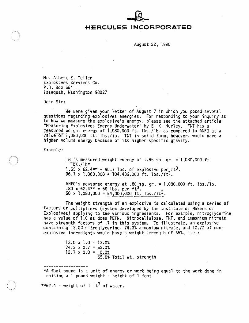
The Institute of Makers of Explosives (IME) uses a system of percentage ratings. An explanation of this rating, ostensibly adopted by the members of the IME, is contained in a letter addressed to me in response to my question, in writing, as to just what the rating system means and how it applies to use by blasters in the field. A copy of that letter is found at the end of this chapter.
It must be kept in mind that there are no regulations of any kind that require manufacturers to give any information or even tell the truth in their advertising. Energy output information can be misleading and can be, and often is, misunderstood. But one thing it is not, and that is-necessary for the blaster in the field. What the blaster in the field needs to know relative to energy is the VOD, density, and critical diameter if applicable.
WATER RESISTANCE
Depending upon their chemical make-up, some explosives will fail to detonate or fail to sustain detonation when exposed to water for periods of time. AN-FO, for instance, is extremely hygroscopic and will dissolve in or absorb water, thereby changing its chemical structure and causing the explosive to fail to detonate. Explosives such as "gelatin" dynamite are impregnated with nitrocellulose (NC) to enhance their tolerance to water (as well as explosive energy) through the waterproofing capability of the NC. Technical data sheets about explosives nearly always indicate tolerance to water as "excellent", "good", "fair", or "poor". As a rule of thumb, an explosive rated excellent will withstand water degradation for an indefinite period, those rated good will withstand submergence for about 24 hours or more, those rated fair last for about 1-3 hours, and those rated poor should not be used in the presence of water.
It should be noted that the so-called "WR" AN-FOs are water resistant, not waterproof. This blasting agent should not be poured into water-filled holes, though it
· can be used where there is some minor seepage or where there has been water and the water has been evacuated through pumping.
SAFETY CHARACTERISTICS
All commercial explosives are subjected·to various tests to determine their safety characteristics. All of the following tests are conducted by the manufacturers, and
10 BLASTING MANUAL
by government agencies as well, including the U.S. Bureau of Mines and the U.S. Army Picatinney Arsenal Testing Facility. The tests and how they are conducted are described below:
drop impact - Weights are dropped from various heights onto the explosiv, which has been placed on a steel plate, to determine sensitivity to impact caused by falling objects. The usual test is a 5-Kg (11 lb) weight (usually a steel ball) dropped from various heights up to 100 cm or 1 meter (39 inches).
sliding rod - This tests the effect of a glancing blow from a steel object to determine if the blow creates smoke, burning, or detonation.
projectile tests - The explosive is tested under impact from rifle, pistol, and shotgun fire. ·
friction pendulum - Explosives are subjected to the friction created by two pieces of steel sliding across the explosive.
burning - The explosive is burned in both small and large quantities, spread out, and piled up, using wood and diesel fuel as the igniting medium, to test the ability to withstand heat.
static electricity - Samples of the explosive are subjected to charges of static electricity in the range of 20,000 volts. Blasting agents must withstand 25,000 volts.
temperature stability-Most dynamites contain enough ethylene glycol, (antifreeze agent) to prevent freezing except under the most rigid circumstances. Dynamite has been left in the Antarctic for 6 months and later successfully used. However, as with most substances, dynamite gets stiff and hard to handle when it is cold. Water gels, on the other hand, since they contain a great deal of. water, will freeze at the freezing point of water and will get stiff and hard · tamp when it is cold. Most will fail to propagate below freezing temperature~. / (See Chapter 3: Types of Explosives.)
shelf life - NG-based explosives undergo changes after periods of time and temperature cycling from hot to cold. These changes do not appreciably effect the energy output of the explosive. Stocks should be rotated periodically so that the oldest explosive will be used first. The shelf life of water gels, emulsions, and slurries, on the other hand, is limited by chemical cross-linking, etc. If the technical bulletin for the particular explosive or blasting agent does not indicate its shelf life in specific terms, the user should request the information, in writing, from the manufacturer's representative. Every case of explosive of any kind has a code date stamped on it. This should be checked before the explosive is used. Most water gels have a shelf life of about 9 months. Any explosive of this type that has a code date older than 9 months should be considered 11.· .~oect.
classification - Explosives are classified by the U.S. Department of Transportation in the following manner:
Class A-Explosives composed of detonatable material such as nitroglycerine, lead azide, etc. All detona~ors, cast primers, detonating cord, cap-sensitive emulsions, water gels, and slurries are Class A.
Class B - Explosives that possess flammable hazard such as propellants, propellant explosives, flash powder, pyrotechnics, etc.
Class C-Explosives that contain Class A or Class B explosives or both, ""t in very small quantities.
blasting agents- these compounds have been defined in the Glossary.
HERCULES IN~ORPORATED
August 22, 1980
Mr. Albert E. Teller Explosives Services Co. P.O. Box 664 Issaquah, Washington 98027
Dear Sir:
We were given your letter of A~gust 7 in which you posed several questions regarding explosives energies. For responding to your inquiry as to how we measure the exp1osive's energy, please see the attached article "Measuring Explosives Energy Underwater" by E. K. Hurley. TNT has a measured weight energy of 1,080,000 ft. lbs./lb. as compared to ANFO at a value of 1,080,000 ft. lbs./lb. TNT in solid form, however, would have a higher volume energy because of its higher specific gravity.
Example:
TNT's measured weight energy at 1.55 sp. gr.= 1,080,000 ft. lbs./lb* .
1 .55 x 62.4** = 96.7 lbs. of explosive per ft3. 96.7 X 1,080,000 = 104,436,000 ft. lbs./ft3.
ANFO's measured energy at .80 sp. gr.= 1,080,000 ft. lbs./1b . • 80 x 62.4** = 50 lbs. per ft3. 50 X 1,080,000 = 54,000,000 ft. lbs./ft3.
The weight strength of an explosive is calculated using a series of factors or multipliers {system developed by the Institute of Makers of Explosives) applying to the various ingredients. For example, nitroglycerine has a value of 1.0 as does PETN. Nitrocellulose, TNT, and anmonium nitrate have strength factors of .7 in this system. To illustrate, an explosive containing 13.0% nitroglycerine, 74.3% ammonium nitrate, and 12.7% of nonexplosive ingredients would have a weight strength of 65%, i.e.:
13.0 X 1.0 = 13.0% 74.3 X 0.7 = 52.0% 12.7 X 0.0 = 0.0%
65.0% Total wt. strength
*A foot pound is a unit of energy or work being equal to the work done in raising a 1 pound weight a height of l foot.
**62.4 = weight of 1 ft3 of water.
HERCULES
Mr. Albert E~ Teller Explosives Services Co.
-2- August 22, 1980
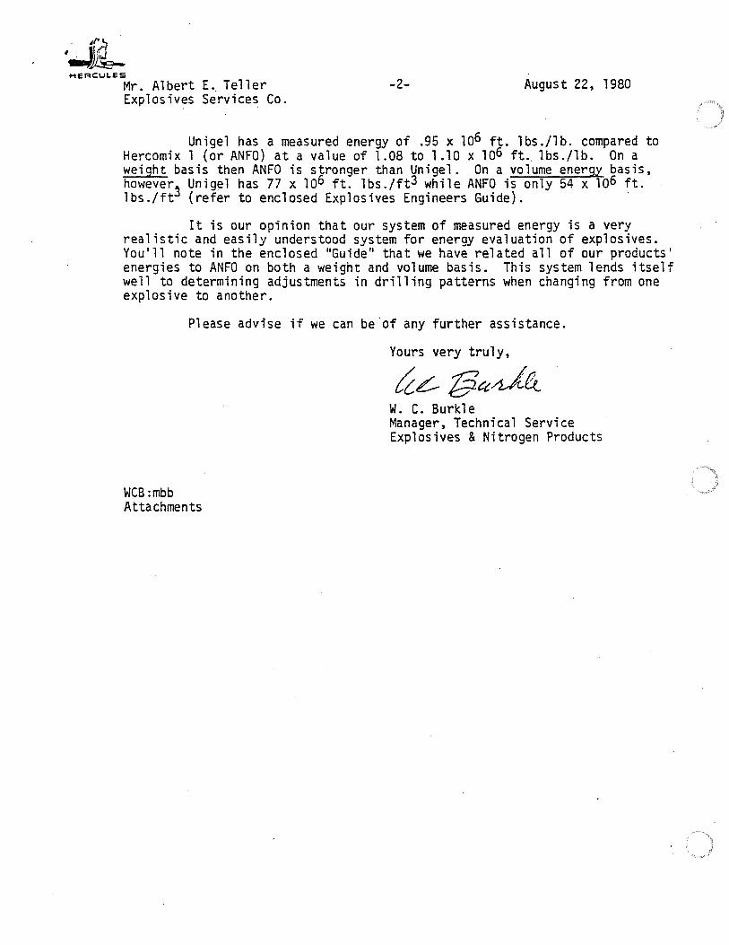
Unigel has a measured energy of .95 x 106 ft. lbs./lb. compared to Hercomix 1 (or ANFO) at a value of 1.08 to 1.10 x 106 ft .. lbs./lb. On a weight basis then ANFO is stronger than Unigel. On a volume energy basis, howeverS Unigel has 77 x 106 ft. lbs./ft3 while ANFO is only 54 x 106 ft. lbs./ft (refer to enclosed Explosives Engineers Guide). ·
It is our opinion that our system of measured energy is a very realistic and easily understood system for energy evaluation of explosives. You 1 ll note in the enclosed "Guide" that we have related all of our products' energies to ANFO on both a weight and volume basis. This system lends itself well to determining adjustments in drilling patterns when changing from one explosive to another.
Please advise if we can be.of any further assistance.
\.JCB :mbb At ta ch men ts
Yours very truly,
(ce::-l3ccd6-w. C. Burkle Manager, Technical Service Explosives & Nitrogen Products
Chapter 3: Types of Explosives
INTRODUCTION
There are three classes of commercial explosives. In the previous chapter, these were noted as Class A, Class B, and Class C. Blasting agents are used as explosives but not directly classified as such. While the "Class .. ifications are instituted by the U.S. Department of Transportation as a means to regulate interstate transportation of explosives, they also denote types of explosives.
CLASS A EXPLOSIVES
There are two types of Class A explosives. All can be initiated with a #6 test blasting cap. NG-based explosives are always referred to as dynamites, while those that have other explosive ingredients are usually referred to as water gels.
Dynamites Dynamites can be made water resistant and even waterproof by the addition of nitrocellulose. Figure 3-1 is a schematic of how the addition of nitrocellulose changes the explosive from one that cannot be used in water to one that will withstand water pressures almost permanently:
I
Blasting gelatin. At the top right hand side of the chart is blasting gelatin. Blasting gelatin is NG with NC added. Blasting gelatin is rarely used except under very special circumstances and need not be considered further.
Nitroglycerine. At the top left hand side of the chart is nitroglycerine. It is never used in construction or mining.
Straight gelatin. The second item on the right is straight gelatin, which has a reduced amount of NG and NC with additives included but without the addition of AN. In general it is NG, NC, and some chalk (yes! chalk) and sodium nitrate. It is seldom used in commercial blasting.
I Nitrocellulose I NITROGLYCERIN I - I BLASTING GELATIN
Oxidizer Fuel Oxidizer Fuel
' ' I STRAIGHT DYNAMITE:
Nitrocellulose _ : STRAIGHT GELATIN I
Ammonium Ammonium Nitrate , , Nitrate
I AMMONIA DYNAMITE : Nitrocellulose I I
i -, AMMONIA GELATIN
Salt Salt
SEMI GELATIN DYNAMITE
1 I , I PERMISSIBLE I Nitrocellulose - I PERMISSIBLE I AMMONIA DYNAMITE I - I AMMONIA GELATIN
Figure 3-1. Nitroglycerin explosives family. (Reprinted from Atlas Powder Company, 1987, Explosives and Rock Blasting, figure 1.3.)
11

12 BLASTING MANUAL
Straight dynamite. The second item on the left is straight dynamite, which is non-waterproof and rarely used except in the 30 percent to 50 percent grades. These are often used in ditching through damp soil, swamps, etc. It does not have good water resistance, and if used in very wet ground, must be initiated a: soon as possible.
Ammonia gelatin dynamite. The third item on the right hand side is ammonia gelatin dynamite (AGD), which is an NG dynamite with the addition of ammonium nitrate. The VOD is lower than either straight dynamite or straight gelatin, and it has a lower density and is less expensive than either of the others.
Ammonia dynamite. The third item on the left hand side is ammonia dynamite, which is the same as AGD but does not contain nitrocellulose for waterproofing. It should not be used in wet conditions.
Semi-gelatin dynamite. In between ammonia dynamite and ammonia gelatin dynamite is found semi-gelatin dynamite. This is a low-velocity, medium-tolow-density explosive, which while it does not have the waterproof capabilities of AGD, is somewhat better than AD, in that there is some NC included in the formulation. Again, it has a lower VOD and density than either AD or AGD.
The De and VOD of all NG-based explosives can be increased or decreased according to the requirements of the project. Actually, both are set by chemical formula, and the individual user must select that which best fits the work at hand.
What's in a name? In the case of explosives, not much, really. Many of the same, or nearly the same, products will carry different names at different prices, ·depending upon the use to which the manufacturer: thinks they should be put, and what the market will pay. Explosives should be selected only on the .basis of what is needed for a specifi application-VOD, density, packaging, water resistance, and/or last but not least, delivery service and price.
Figure 3-2 lists the properties of Atlas NG dynamites:
In the chart, there are trade names. It is well to note that the name of the explosive does not always indicate its real properties. A good example is "Extra Dynamite". It is not extra at all. It is a low-velocity, low-density ammonia dyna-
Absolute Delonoflon bulk Relawe Confined
DeNlly pf8SSUfe sltenglh bulk strength velocity Waler Fume
(g,/cc) (kbof) (cot/cc) (ANFO = 100) (ff/sec) resistance class
Petrogel 1.5 140 1,600 217 20,000 Excellent N/A
Sels-Prlme 1.5 140 1,600 217 20,000 Excellent N/A Power Pllmer 1.36 135 1,460 198 18.000 Excellent 1 Power Dltch 1000 1.36 135 1,450 195 18,000 Excellent 1 Hi-Prime 1AO 130 1.410 191 20.000 Excellent N/A
Gian! Gelalln 1A8 75 1.320 180 15,000 Excellent 1
Power Oltch 750 1AO 83 1.400 190 16.000 Goad. 1
Aa11ge1330 1.55 44 1,100 149 11,000 Excellent N/A
Gelmax 1.28 67 1,175 159 15.000 Goad·
Power Oltch 500 1.28 67 1,180 160 15,000 Good
Exira Dynamite 1.29 45 1,005 136 12,000 Fair 1
CoalileSP 0.88 17 665 90 8,700 Poor p
CaallleSMR 0.94 25 660 09 10.500 Poor p
CoalileSU 1.07 27 845 115 10.500 Fair p
CoalileSUl 1.07 30 815 110 11,000 Fair p
Coalile BS 1.18 34 960 130 11,000 Goad p
Caallle8R 1.18 34 930 126 11,000 Goad p
Gel-Caallle 3 1.19 40 1.105 150 12.ClOO Good p
Gel-Caallle Z 1.33 89 1,215 165 17,000 Excellent p
Kleen-Kut C 1.28 58 1,185 160 14,000 Good N/A
Kleen-Kut E 0.88 17 690 93 9,200 Poor N/A
Kleen-Ku!U 0.88 17 765 104 9,200 Poor
Nate. P = explosive meals "pennlsslble fume standards"; N/ A = not applicable.
Figure 3-2. Properties of Atlas nitroglycerin explosives. (Modified from Atlas Powder Company, 1987, Explosives and Rock Blasting, table 3.3 .)
CHAPTER 3: TYPES OF EXPLOSIVES 13
mite with a bit more AN added than is found in the higher-velocity, higher-density AN dynamites. It is from that extra AN that it probably gets its name.
The chart shows an explosive called Petro-Gel. This is an explosive used for oil exploration as well as a process called "fracking". into which we need not go in this manual. It is basically a straight gelatin. ·
Seis-Prime is not all that different from Petro-Gel, and it is used pretty much for the same purposes. The difference may be that the Seis-Prime has cartridges that screw into each other so that the charges can be lowered down a borehole one at a time.
Packaging Dynamite packaging is generally in "sticks" (Fig. 3-3). The sticks range in si~e from 7/s" x 12" for pre-split explosives, which weigh about .25 lbs. (There is a mystique, untrue of course, that pre-split charges should be .25 lbs of explosive per foot of borehole.) The 1.25" x 8" sticks weigh about .5 lbs each. The 2" x 16", a ubiquitous size used as a primer for AN-FO among other things, weigh about 2.2 lbs each. The 3" x 16" sticks weigh about 5 lbs each. In very large diameter holes, such as those used by the Mesabi Range and other open pit mines, some dynamite charges come as large as 8-1 O" in diameter and weigh 200 and even 300 lbs. All are "sticks". In the future, if anyone asks how much damage can be done by a stick of dynamite, ask first, "What size stick are you talking about?"
Advantages of dynamites
• Easily initiated with a #6 commercial cap.
• Relatively impervious to weather conditions, hot or cold.
• Generally high VOD and De,
• Generally good water resistance (gelatins, and semi-gelatins only).
• Excellent propagating capabilities.
• High gap sensitivity.
• Will sympathetically detonate in water in case sticks "float" in water-filled holes.
Figure 3-3. Dynamite products. (Reprinted from Atlas Powder Company, 1987, Explosives and Rock Blasting, figure 3.4.)
14 BLASTING MANUAL
• Can be obtained in varying types of packaging and varying sizes.
• Needs no priming.
Disadvantages of Dynamites • Requires special magazines for storage.
• Generally higher in cost than water gels.
• Nitroglycerine headaches.
• Use, storage, handling, and transportation closely regulated by a variety of agen-cies.
• Post-blast fumes are somewhat toxic.
• Non-gelatin dynamites are not compatible with water.
Water gels Water gels, slurries, emulsions have been on the market since the late 1960s. In the early 1970s, DuPont Explosives (now ETI) announced that it would no longer produce d)'.namites, but would concentrate only on water gels, slurries, and emulsions. DuPont marketed its water gel as TOVEX™. DuPont also predicted, through articles in trade magazines written by their tech reps and distributors, that in 10 years there would be no dynamite manufactured.
There can be no doubt that water gels, etc., have made extremely heavy in-roads into the dynamite market.
Water gels, slurries, and emulsions consist of a solution of oxidizers suspended in microscopically fine drops that are surrounded by a fuel. The mixture, an emulsion, is stabilized by addition of an emulsifying or gelling agent. This agent determines and controls the density of the compound, which can run from .85 gr/cc to as higlas 1.35 gr/cc with a detonation velocity from 19,000 fps to as low as 14,000 fp, In small diameters, (1 Y4") the VOD may well go below 14,000 fps.
Figure 3-4 shows the advertised technical data for Atlas Emulsions (now ICI, USA) found in an excellent book about about explosives entitled "Explosives and Rock Blasting .. , which was published by Atlas and can now be obtained from ICI, USA, 15301 Dallas Parkway, Dallas, TX 75248, or any distributor of Atlas or ICI products).
Water gels are relatively rigidly packaged and are fairly granular when the packages are slit. Emulsions, on the other hand, tend to be more oily and will ooze rather rapidly when the packaging is cut or slit. It must also be stated that ICI produces an emulsion that is cap-sensitive, packaged in cardboard containers or in parafined paper wrappers, and is grainy and not the least bit oily. The cartridges can be, and often are, slit or cut in half.
Water resistance of water gels is generally excellent, even when the cartridges are cut or slit for tamping in the hole. Water found in a borehole will rarely have a temperature below about 45°F, so cold water will have little effect on performance.
Temperature is a distinct and important concern when using cap-sensitive, as well as non-cap-sensitive water gels. It is a subject that manufacturers would rather not discuss too openly. Too often, however, blasters who are not familiar with the temperature limitations of water gels, slurries, and emulsions, find themselves with unbroken rock, cartridges scattered across the landscape, and if a sub-contractor, confronted by a red faced, angry, cursing individual with an 18" crescent wrench in his hand. Too often at this point, the distributor of the explosive or the techni, representative is seen only as a distant figure in a car, heading to his next blast. Much as the Ensign-Bickford Company, which manufactures detonating cord under the trade name "Prima-Cord', never admitted or even mentioned the problems of "dead-press" or· stemming ejection when detonating cord is used as a "down-
CHAPTER 3: TYPES OF EXPLOSIVES 15
line", so too, there are few caveats (Latin for beware) warning of temperature problems from manufacturers of water gels.
Water gels are relatively easy to use in temperatures above 35°F. As temperatures drop below that point, heavy priming is required. Even though the explosive is ostensibly cap-sensitive, most require that special primers be placed over the cap before it is used to prime the cartridge. Below about 20°F, the user should get some assurance (in writing or on a published tech sheet) that the suggested priming will cause detonation and propagation of that detonation up the borehole. Water gels also become rather stiff and difficult to slit or prime in temperatures of 35°F and below.
Advantages of water gels
• Less expensive than dynamites, but not much.
• No dynamite headache (which is an advantage for some people).
• Less sensitive to detonation from impact by a bullet.
o Almost always water-proof, even when cartridges are slit.
Disadvantages of water gels • Temperature sensitive (product temperature, not ambient temperature).
• Often has low density.
• Gap sensitivity is so small as to be non-existent.
• Some water gels tend to ooze when slit.
• The material will stick to borehole walls.
• Shelf life is limited to about 9 months.
Absolute Relative Detonator bulk bulk
Density Velocity pressure strength strength Water DOT (g/cc) (ft/sec) (kbor) (col/cc) (ANF0=100) resistance clossficotlon
Powermox 120 1.15 16,000 100 775 105 Excellent Explosive A Powermox 140 1.16 15,000 100 1,095 · 148 Excellent Explosive A Powermox 420 1.19 19.000 100 820 111 Excellent Explosive A Powermox 440 1.19 18.500 100 1.140 154 E.xcellent Explosive A Powermox 460 1.21 17,500 90 1,310 177 Excellent Explosive A Powermox 840 1.35 19,000 _a 1,275 172 Excellent Explosive A PowerSels 1.45 16,000 93 1,255 170 Excellent Explosive A Atlas 7/D 1.18 16,500 _a 890 120 Excellent Explosive A Apex 220/320 1.25 19,000 105 850 115 Excellent Blasting Agent Apex 240/340 1.25 18,500 100 960 130 Excellent Blasting Agent Apex 260/360 1.25 18,000 _a 1,070 145 Excellent Blasting Agent Apex Plus 1.30 14,000 _a 985 135 Excellent Blasting Agent Apex 1220/1320 1.25 19,000 _a 850 115 Excellent Blasting Agent Apex 1240/1340 1.25 18.500 _a 960 130 Excellent Blasting Agent Apex 1260/1360 1.25 18,000 _a 1,070 145 Excellent Blasting Agent PowerAn 300 1.18 13,000 _a 1,035 140 _b Blasting Agent PowerAn 2500 1.15 12.000 _a 1,035 140 Poor Blasting Agent PowerAn 5000 1.30 16.000 _a 1,035 140 Good Blasting Agent PowerAn 7500 1.26 18.000 _a 902 122 Excellent Blasting Agent
0 Not used as a primer.
b Dependent upon package integrity.
Figure 3-4. Atlas Emulsion Explosive System technical data. (Reprinted from Atlas Pow-der Company, 1987, Explosives and Rock Blasting, table 4.4.)
16 BLASTING MANUAL
CAST PRIMERS AND DETONATING CORD
Cast primers and detonating cord are both now considered as Class A explosives. Detonating cord was, at one time, considered Class C and even Class D. In thr 1960s, it was not unusual to ship rolls of detonating cord on common carrier~. including and especially the Greyhound Bus.
Detonating cord
Detonating cord has a VOD.of approximately 22,500 feet per second. The explosive used in the cord is either PETN (£.enta~rythra!etra,!!itrate) or RDX or a mixture of both. The core of explosives is contained in a plastic tube, which is wrapped in a fiber wrapping, which is wrapped in a distinctive plastic cloth, which usually has a black tread running through it. Detonating cord is available in low-energy cord, at about 2.5 grains per foot, through 10 grain, which is sometimes called quarry cord, through 25 grain, 50 grain, I 00 grain, 200 grain, and 400 grain. Each has a distinct color-coded wrapping on the outside (Fig. 3-5).
Detonating cord has often been used as a "down-line" to initiate explosives in boreholes. In the case where a cap-sensitive explosive is in the borehole, wherever the detonating cord touches the explosive, initiation will most assuredly begin. Obviously, if this occurs, top initiation, rather than bottom initiation will take place.
If detonating cord is used in a borehole filled with AN-FO, there will be a loss of the energy normally expected of the AN-FO. The flash of flame caused by detonation of the cord burns off the FO on the surrounding AN. In addition, the shock waves produced by the detonation will crush or "dead-press" the AN to the point where it will not detonate.
The uses to which detonating cord can properly be put are:
• Connecting widely separated charges for instantaneous detonation.
• Initiating some types of non-electric delay blasting cap systems.
• Connecting underwater charges.
Figure 3-5. Detonating cord with the Atlas G booster. (Reprinted from Atlas Powder Company, 1987, Explosives and Rock Blasting, figure 8.19.)
CHAPTER 3: TYPES OF EXPLOSIVES 17
Cast primers
Cast Primers are cy tinders of :varying diameters and lengths, made of PETN, Penolite, RDX, and other high velocity explosive material. On one end there are two holes, large enough for a blasting cap or 25-grain detonating cord to be pushed through. The other end has one opening. The blasting cap is threaded through the single hole, then looped and threaded through the second hole. As shown in Figure 3-5, detonating cord is simply threaded through one hole and knotted at the other end. Primers are sold in weights ranging from half a pound up to several pounds. The primer shown in the figure is one pound in weight and about 2.sn in diameter.
Cast primers are used to initiate non-cap sensitive explosives, and blasting agents. While the high VOD produced by these primers aids in obtaining good detonation of the non-cap sensitive explosives, care should be exercised to be certain the the diameter of the primer is at least half the diameter of the borehole, to insure complete high velocity detonation of the donor charge.
BLASTING AGENTS
There are two types of blasting agents (BA): (1) wet blasting agents and (2) dry blasting agents.
Wet blasting agents
Wet blasting agents are emulsions or slurries. They are packaged in sausage-like plastic. For the most part, the sausages can be slit along their long axis, dropped into the borehole, and tamped using "powder poles", so that the material will fill the entire hole, or they can be used without slitting and simply dropped into the boreholes.
Critical Diameter
Many of the BA slurries and emulsions require a mass of material to reach steadystate velocity. Most will not detonate properly below 3n in diameter. Some require even larger diameters. In any event, it is necessary that either the technical representative of the manufacturer be contacted to determine critical diameter or it can be ascertained by carefully reading the technical sheet for the particular agent that is to be used. If the technical data sheet starts out with VODs at 3n or 4n, do not use the material in boreholes of smaller diameter, even if poured.
Priming wet blasting agents
All wet blasting agents must be heavily primed to insure proper detonation. When making decisions regarding wet, as well as dry, blasting agents, care should be exercised to insure that the initiating charge has a VOD at least a high as the blasting agent and preferably 25 percent greater. For wet blasting agents follow the following principles. The primer should:
• Have a detonation pressure greater than the blasting agent.
• Match as closely as possible the column diameter of the agent.
• Have adequate length (mass) to insure proper detonation.
Acceptable primers include: high-velocity ammonia gelatin dynamite, high-velocity ammonia dynamite, cast primer.
Primers that should not be used to prime wet blasting agents are: semi-gelatin dynamite, low-VOD ammonia dynamite, cast primer with diameter less than half that of the borehole.
Advantages of wet blasting agents
• Lower cost than dynamites or Class A water gels and emulsions.
• High VOD and/or density.

18 BLASTING MANUAL
• Can be made to fill the entire borehole.
• Class A magazines are not required for storage.
• Can be used at the bottom of boreholes to insure breakage at and above grade.
• Will sink through water and is waterproof.
Disadvantages of wet blasting agents • Requires heavy priming.
• Must have absolute contact between cartridges.
• When cartridges are slit or material is poured, may "slump" or hang up in the borehole.
• Highly temperature sensitive.
• Shelf life is short (9 months?).
Dry blastlng agents Dry blasting agents come in a variety of mixes. The most common of these is ANFO. AN-FO lias been defined as a combination of ammonium nitrate prills and fuel oil (diesel oil). Some, however, have aluminum filings or aluminum powder added to increase detonation velocity (slightly) and the heat of the explosion. Some ANFO mixes contain a gelling agent to add a slight degree of water resistance. These are often referred to as WR AN-FO. As noted previously, this blasting agent should not be poured into water-filled holes or used where there is water in the bottom of the hole.
voe of AN-FO mixes
One of the least understood properties of AN-FO is the effect that charge diametel" has on VOD. There are any number of things that will change the detonation n of AN-FO. These include:
• Prill size (the smaller, the better).
·• Solidity of the prills (the fewer air spaces, the better).
• The degree of or lack of coating to reduce hygroscopicity.
• Charge diameter.
• Temperature cycling.
• Ambient humidity (related to hygroscopicity).
Prill size, solidity, and coating are carefully controlled by the manufacturers. Temperature cycling refers to continual change from cold to hot, from dry to damp weather, and is only marginally controllable by the user. If the AN-FO shows any sign of "clumping", or prills sticking together, it should be discarded. This clumping is caused by constant changes in temperature or in humidity. As noted, AN-FO will absorb water very readily, and that includes humidity as well.
Charge diameter Charge diameter on the other hand, is controllable by the user. Since AN-FO is poured into boreholes to fill the entire annular space, the dependence upon borehole diameter for VOD is critical.
Below are approximate VODs for various-size boreholes. These may vary a bit, depending upon the mix, size of prill, etc. They are accurate for most mixes:
1 Yz" diameter 2" diameter 3" diameter 4" diameter 5 "+ diameter
7 ,000-8,0000 fps 9,000-10,000 fps 10,000-12,000 fps 13,000-14,000 fps 15,000 fps
CHAPTER 3: TYPES OF EXPLOSIVES 19
Color The color of the AN-FO in no way adds to, or detracts from, the VOD of the mix. We are all familiar with advertising that says, "Our product is now New and Improved". That may or may not be true with laundry detergents, but it is not true witl. AN-FO. At least not because color has been added. The color is added for visual assurance that the compounds have been properly mixed.
Packaging
AN-FO packaging is simple and effective. Most AN-FO is packaged in SO lb, (25 Kg in Canada and Overseas) bags, which have a thin polyethylene liner to keep moisture out. To load the mix into boreholes, the top is slit and the prills simply poured into the borehole (Fig~ 3-6).
Additional priming
Additional priming is often recommended by manufacturers. This means that additional sticks of dynamite or primers are dropped into the borehole, along with the AN-FO, to "keep it going", whatever that means. Some manufacturers recommend additional priming every IO feet if the column is over 30 feet long. There is no evidence to show that this is really necessary. If the column will detonate 20 feet or 25 feet, it will certainly detonate 30 feet, SO feet, or even 100 feet. Steady-state velocity of AN-FO is determined in large part by the borehole diameter. All primers are normally placed at the bottom of the borehole. In fact, it is well to remember that priming should be at the point of maximum confinement. If the bottom of the borehole is at or close to a soft formation, dirt seams, or cinders, etc., priming should be higher than the bottom of the hole to insure that all the blast effect does not travel down instead of up. This is not a usual circumstance by any means. The steady-state velocity of AN-FO will not vary much regardless of the primer used. The SSV will be reached within 1-3 borehole 9iameters. The VOD a
,,.
-~
~~-~ "'. ,,..,. .. ·-·· C?~
Figure 3-6. AN-FO mix packaged in 50-lb bags. (Reprinted from Atlas Powder Company, 1987, Explosives and Rock Blasting, figure 5.3.)
20 BLASTING MANUAL
the point of initiation will be roughly the same as that of the primer. The VOD will drop to the steady state noted above very rapidly. If the AN-FO is underprimed, the initial velocity will be low, and steady state will not be attained quite as readily as if it were properly primed. The same requirements that apply to wet blasting agents apply to AN-FO.
Heavy priming
Heavy priming of AN-FO loaded holes is required, as it is with any blasting agent. The three controlling features of a primer are its VOD, diameter, and length. Figure 3-7 indicates the effect of the type of primer used. The higher the .. K" of the explosive, the higher the initial VOD. As the K decreases, the initial velocity decreases, to the point where an explosive with a low K (9 bars) requires an increase to steady state and may very well cause a low-order detonation. Figure 3-8 shows the effect of the diameter of the primer. In this instance, a 1"-diameterprimer, even though it has 240 Kbars of DP, starts at a low VOD and drives the column up to steady state. Here again, it is possible that SSV may not be attained.
Using a small-diameter, low-velocity explosive as a primer for any blasting agent, especially AN-FO, is false economy at its best. Nonetheless, it is a common practice. There are those who feel that AN-FO is the only explosive to use because it is the one most commonly used. What must be remembered is that 75 percent of all boreholes used in the U.S. are in excess of 5" in diameter, which is where the VOD will reach 15,000 fps. In smaller-diameter holes, the VOD of AN-FO rarely reaches 14,000 fps, and therefore is not high enough to match the V so of hard rock. In addition;the De of most high explosives is well above that of AN-FO, therefore attaining more pounds per lineal foot of borehole, which allows for greater spacings and burdens and a definite reduction of the drilling required. In most cases where hard rock is encountered, matching VOD and V so allows for lower powder factors, reducing drilling costs even more through extended spacing and burden. Drilling is the most expensive part of blasting small-diameter holes.
24,000 A
Detonation
9!!Y! Primer Pressure of Prim•r - A Cast Pentolite 240 kbar u (I) 20,000 B Ammonia Gelatin Dynamite 135 kbar (II = C Extra Dynamite 40 kbar -C D Permissible Dynamite 9 kbar
E :::)
16,000 0 (.)
0 u. z <( 12,000 0 ~ u 0 'a; 8,000 > D
4,000 +----.---.....----,---.,.----,----.-----r--...---, 0 4 8 12 16 20 24 28 32 36
Inches from Primer
Figure 3-7. Effect of detonation pressure on the initial velocity of AN-FO in a 3-inch diameter test column. (Reprinted from Atlas Powder Company. 1987. Explosives and Rock Blasting, figure 8.1.)
CHAPTER 3: TYPES OF EXPLOSIVES 21
Advantages of AN-FO
• Low cost.
• Fills the entire borehole, thereby attaining coupling.
• Requires no special storage magazines.
• Has high VOD in large-diameter boreholes.
• Easily poured into borehole
Disadvantages of AN-FO
• Hygroscopic; will absorb moisture readily and become desensitized.
• Low density, requiring close spacing of boreholes.
• Low VOD in small diameter holes.
• Requires additional priming.
16,000
14,000
-(.) ~ Cl)
12,000 = -0 LI. z
10,000 < -0 ~ ·u 8,000 0 'ai >
6,000
4,000 0 4 8
Diameter of Detonation Pressure of Primer (In.) Primer (kbar)
12
3 240 2-1/2 2
16 20
240 240 240
24
Normal Velocity
28
Distance From Point Of Initiation (In)
Figure 3-8. Effect of diameter on the initial velocity of a 3-inch column of AN-FO using cast Pentolite as a primer. (Reprinted from Atlas Powder Company, 1987, Explosives and Rock Blasting, figure 8.2.)

22 BLASTING MANUAL
Tovex 700 and Tavex BOD are cap-sens1t1ve cartndged water gels. These products are for applications in boreholes with diameters ranging from 2" (50mm) to 6112'' (165mm).
Both products are of the same density, but they have basic differences in that "Tovex" 800 has the higher energy and it is sensitive to cap initiation at a lower temperature (to 20°F).
properties and specifications Performance .. Tovex·· 700-Medium density.
velocity and energy ''Tovex" BOO- Medium ce~s1ty. medium velocity. high energy.
Density "Tovex" 700-1.20 "T ovex .. BOO - 1 .20
Energy
Tovex .. 700
II II i U ~ 0 b O II I U I ., I ~
ENERGY tCAL cc • IU I
Velocity (Confined in 2· Pipe at S0°F} -·· ·--·· .. -
(M/sec)
"Tovex" 700 4.800
··Tovex .. BOO 4.800
Fume Class 1 available on request. Classification Explosives Class" A".
Shelf Life One year stored at ambient temperatures.
(ft/sec)
15.750
15.750
I I I I
~--_,,,,,,X ..... ___ ~X~--"Tovex" 700 and "Tovex" 800 have both shown good suitability for blasting hard rock and ore in mines. quarries and construction.
Through the use of "Tovex" 800, an enviable standard of performance has been set. and this grade remains the most popular of the Du Pont "Tovex" water gel products for the 2" to 61/2" diameter hole size range.
Cartridge Count Cartridges are of plastic tubing 16" (400mm) long. packaged 50 lb. per case in
high strength boxes.
Diameters "Tovex" 700 "Tovex" 800
P,,· (45mm) 29 2" (50mm) 22 2v,· (55mm) 18 2112· (65mm) 15 2:v,· (70mm) 12 3· (75mm) 11 31/.a" (85mm) 9 3h" (90mm) B 3=¥," (95mm) 7
These products are available in 4·· and s· bag pack on request.
Priming Requirements "Tovex" 700 - One standard cap (#8) to SCl°F or Detaprime" UA or UF to 3Cl°F. "Tovex"' BOO - One standard cap (#8) to 2Cl°F.
NOTE. Not compatible with Primalinet. Therefore, may not be used with Pnmadetst or Nonel HD Primadetst except for top priming with "Tovex" column and when no knots contact the "Tovex". •Tr&aem&ras or 1n1 Ens"ln Bocaloro Comp&ny
Water Resistance Maintains performance after exposure to a 100-foot water head for 24 hours. If the package is removed. the water resistance 1s decreased.
advantages Cap Sensitive No supplemental primers are required tor product used in most applications.
Product Selection The range of strengths. velocities and densities provided by Tovex M
700 ano 800 water gels permits desiraole matching of explosives and rock properties.
Loading The wide choice of cartridge diameters allows llex1011tty in blast design and hole 1oad1ng.
.Non-Headache ··Tovex" 700 and 800 contain no headache-causing ingredients.
Fumes ··Tovex·· 700 and 800 offer an aopreciaole reduction 1n· noxious gases and smoke associated with nitroglycerin dynamites.
Increased Safety .. Tovex" 700 and 800 provide increased safety to the consuming industry due
to lower sensitivity to impact. shock. and fire when compared to nitroglycerin dynamite. Water Resistance "Tovex" 700 and 800 offer superior water resistance to standard gelatin and semi-gelatin dynamites.
Non-NG "Tovex" 700 and 800, when initiated with caps or Detaprime • -provide a totally nonnitroglycerin blasting system which offers increased safety.
Freezing Alternate freezing and thawing does not impair the pertormance of "Tovex .. 700 and 800. nor reduce their safety characteristics.
Hole to Hole Propagation "Tovex" grades are designed to minimize propagation between holes in normal drill patterns ... provided no nitroglycerin explosives are included 1n the load. Therefore. any delay method designed to improve fragmentation and reduce vit.ration should function properly.
,, : .,,,f'''"' : ••.•·••·•·· ,1•·:.,•1•1Ji ••. ,,1 t:1 0 ,-,, tif,.,,,, .. 1,., .• 1,,,: H•• .. 1,,, ... ,1 ;r,1·,.,..,,;:i.,rt .. fCwf"'-.111l~c•..,11 .. ..:!1.•,· ,n~\IO'ct')
•••• , ' ;,. :•, !t • t If' !• t,,:1 •!•,,I••'·•· I•·, t t'I ,11,:, lt,t• 11 t 't, '·I" I• .•,.: t! •r • ,: ,,#•I h ,, H: 1,,,11,tfh!to'," [h, i',,fd ,f ,t••, t,,,f
• • 1. • ti••• t• •• •. u•·t 1•. "!t,t . I • l•,e, • 1 • • • •tfHt•, ':,, t .-,,:t •t,,· ,,•,, ,,Iii°" ••••f•,• ,l.1•t1 • (f P ,tf1•1,,,l ,t1!o•f •h 11.1• tlu 1·C,..,1•h1
.• • I • ! t i •' ;t ff • t •· J,tl ,. • . ! • I.•.• 11 1 •• t I ,:.t f ~ ,af• I ,I ,
E.1. du Pont de Nemours and Co. (Inc.} Explosives Products Division WIimington, DE 19898 district sales offices
CHARLESTON DISTRICT 1123 Charleston National Plaza Charleston. West Virginia 25301 (304) 343.7549
CHICAGO DISTRICT 1250 Execultve Park-Suite 301 Geneva. lthnq,s 60134 (312) 232-2757
DALLAS DISTRICT 4141 Blue Lake Circle-Suite 168 Dallas. Texas 75234 (214) 258·1636
DENVER DISTRICT 445 Union Boulevard-Suite 304 Denver. Colorado 80228 (303) 988-2744
KENTUCKY DISTRICT 2265 Harrodsburg Road Lexington. Kentucky 40504 (606) 276-4302
NORTHEAST DISTRICT 9800 McKnight Road-Suite 301 Pittsburgh. Pennsylvania 15237 (412) 367 ·2003
SEATILE DISTRICT 400-108thAve .. N.E.-Su1te 601 Bellevue. Washington 98004 (206) 455-4500 .
SOUTHEAST DISTRICT # 15 Ottice Park. Mountain Brook Birmingham, Alabama 35253 (205) 879-0465
EXPORT SECTION Wilmington. Delaware 19898 Telex. 83-5429 (302) 774.4951
J
Ears 75.2 I Cv n I 'j l '-' r\L ..
ONE ®
NONEL R
The Explosives Industry hos long· scught a nonelectrical delay detonot0< which would possess the advantages but none of the disodVantages ot electric blasting caps. The preblem hos been the means to reliably transmit a signal to a cap without affecting the explosives commonly used. Nonel. a revolutionary new product meeting this need. hos been introduced by Nitro Nebel AB of Sweden. Nitro Nebel AB. the first of many companies fcunded by Alfred Nobel. has one of the World's foremost commercial explosives research laboratories. Nonel. a completely nonelectric. non-disruptive signal transmission system provides· the basis for a major advance in delay blast initiation ted"lnology. Ensign Bickford. under a license agreement with Nitro Nobel. will manufacture and mcrket Nonel.
None! is a thin. tough plastic tube mode from Surtyn-!> with a thin coating (one pound per 70.000 feet) of reactive material on the inside surface. When initiated. this tube will reliooly transmit a low energy signal from one point to another by means of a shock wove phenomena much akin to a dust ex· plosion. It will reliably propagate this detonation around sharp bends and through kinks. Because the detonation is sustained by such a small quantity of reactive material. the outer surface of the tube remains intact during and otter functioning.
ADVANTAGES 1 . Completely safe from electrical and
radio frequency hazards.
2. Insensitive to impact. shock. and friction
normally encountered in mining operations.
3. High functional reliability.
4. No noise disturbance.
5. Compatible with (will not detonate) oil available commercial explosive products including the most sensitive dynamites.
6. Insensitive to initiation by fire. either unconfined or confined in any quantity.
USE None! can be initiated by detonating cord or a blasting cap. Nonel is a signal transmission system that will reliably initiate instant°' delay blasting cops. Nonel is ideally suited for precision nonelectric delay initiation products. Ensign Bickf0<d will market several Nonel based nonelectric delay detonators to meet blasting needs. None! is available only in toctOl"y assembled products. not on reels. This technical bulletin hos been prepared to inform you about the new and unique features of None!. Technical bulletins concerning None! products ore available from Ensign BickfO<d. Post Office Box 7. Simsbury. Connecticut ~70.
TECHNICAL DESCRIPTION Appearance:
Dimensions:
Powder Weight: Detonation Velocity:
Transparent plastic lube 0.12 inehes O.D. x 0.08 inches I.D. 0.1 groins per toot
6.000 feet per second
Ensign Bickford @@[ITru[9)®rmW BLASTING PRODUCTS DIVISION 660 Hopmeadow St. Simslj>ury, Conn. 06070
t:C C rrm -t -z
... ctmmonia-gelatins-the standard of the industry-that combine high den·sity with high velocity.
• High detonation pressure results in good fragmentation.• High density and high velocity under confinement result in high effective borehole pressure. • Excellent water resistance.• Fume Class 1.
USE Giant gelatins are widely used as an efficient and economical bottom charge in quarrying, mining, construction, river crossings and underwater ditching applications where the high detonation pressure and high effective borehole pressure overcome hard rock blasting problems; They are also used extensively in underground mining and tunneling where high performance and good fume properties are required.
PROPERTIES AND SPECIFICATIONS
"'• "f. Velocity. los ve1oc,1v. tos Oe1ona11on G,a,1e Cartridge WetQIII (tonhneo ,n (unconhned} or~ssure.
Stren91n Strenc;tll o,oe I 'It• x 8"1 1 "• ,, I 8'' ~,looars
60°0 60 50 18000 16000 120 40°0 40 32.7 15000 12000 75 30°0 30 24.5 10500 7000 30
Cartridge Size Length {inches)
2Yz" x 16" (12 ctgs./50 lbs.) 16 2V:" x 24" {8 ctgs./SOlbs.) 24 3" X 10 lbs. 26 3 112"x101bs. 20 4" X 16~ lbs. 26 5" X 25 lbs. 25 5 V2" x 25 tbs. 22 6" X 331/3 lbs. 24 6V2" x 331/3 lbs. 22 7" X 50 lbs. 28 8" X 50 lbs. 22
NOTE: Lengths given are for 40% strength. For 60% add 1 to 2 inches. For 30% subtract 1 to 2 inches. Sizes given are for Style 26, 2V2"-3V2" diameter, and Style 23G. 4" diameter and up.
PACKAGING
...
~;:~:
,-· ,--·· =-i : :;·; ~------
•····· i ' '
Giant gelatins are available in three strengths-30%. 40°0 and 60%-and in a complete range of sizes. Packaged in sprayed shells. with or without the Redi-Slit"' feature. Redi·
M,n,mum numDer or r eartrulges per 50 IDs. Oens,ty 1ma11mum IO"f. morel
t• 1 ~'•" t'I, ... 1Y1"• '"·"· 2··
1.43 149 123 99 66 50 381 1.53 138 114 92 62 47
35 I 1.7 131 106 85 58 44 33
• Also available in 16" lengtns.
Slit cartridges when tamped fill the borehole more completely and make more efficient use of the power inherent in the explosive. Also supplied in large-diameter cartridges.
REGIONAL OFFICES------------.
EASTERN P.O. Sox 2354. Wilmington. Del. 19899 (302) 478-6200
SOUTHEASTERN P.O. Sox 319, Knoxville. Tenn. 37901 (615) 546-6070
CENTRAL P.O. Sox 87, Joplin, Mo. 64801 (417) 624-0212
WESTERN P.O. Box 5045. San Mateo, Cal. 94402 (415) 341-5891
INTERNATIONAL 16201 SW 95th St., Miami. Fla. 33157 (305) 238-6632 Cable: ATPOWCO Telex: 51-8946
Neitner the manufacturer or seller of the products descnt:>ed herein makes any warranty of any kind. express or imphed. otner tnan tnat the products shall be of mercnantable quality. The properties and characteristics stated and the methods discussed are based on researcn and experience and are believed to t>e accurate. but purchasers should make their own tests to determ,ne the suitability of such products and applicability of such methods for their particular purpose.
Statements concerning the use of the products described here,n are not to be construed as recommending the Infringement of any patent, and no liability for infringement arising out of any sucn use is assumed.
In no event shall either manufacturer or seller be llabte for con· sequential damages or expenses.
~ Gulf Explosives ~ Technical Data
Gulf Slurran* 815 High Strength Water/Gel Blasting Agent
Description Gull "Slurran" · 815 is a high
energy water gel that. due to its non- cap sens1t1vity. is classified as an NCN product Slurran 815 contains aluminum 1n ,ts formulation. producing a grear amount of h~a, and energy. wn1ch 1s a prerequisite tor excellent fragmenta· t,on and broken rock d1splace
. ment Slurran 815 is impervious to
water. either 1n or out of !he polyethylene tube. Total hole coupling can be obtained by splitting the tube prior to loading or it can be removed from the tube and loaoed in the drill hole.
Slurran 815 requires priming with a high velocity explosive. such as Gulf's Oetagel" or cast primers.
Properties Density ______ 1.27 gm/cc Velocity _______ 15.000 fps in
4-lnch Diameter Confined
Weight Strength __ 52% M,n,mum Hole
Diameter ___ Four Inches Water Res1stance_Excellent
Advantages Non-headache - Slurran 815
does not contain any ingredient that will cause headaches. either from handling or from muck pile fumes. 2 Non-cap sens1tive-Slurran 815 1s c1ass1f1ed as an NCN. therefore. ,r can be shipped and stored unaer NCN regulations. 3. Satery-Slurran 815 is a very safe explosive. It will not accept · detonation from the scuff. rifle. or drop test.
Packaging Polyethylene tubes in fiber
cases. polywoven tubes. or bulletnosed fiberboard tubes
Approximate Diameter Weight Length
4" 16.5# 34"' 4 1/2" 25# 38" 5" 30# 34" 5V2" 35# 38" 6" 40# 30" 7" 50# 28" 8" 50# 21"
Priming Slurr;,in 815 should be primed
w1rh a high density and high vt!loc,ty primer. sucn as Gulf's D0rage1 or cast primers. The o,gger the primer. the more area ,it ,;ontdct there will be with the w.-1,~'r QP.i Tn,s assures a more r.ip,a drnval of the explosive column at steady state velocity.
Classification Ox1d1z1ng Material .. N,tro-Caroo-N,rrate
Storage and Safety Recommendations -
Gulf Slur ran 8 t 5 water gel is a r0,t·u-..;aro0-nitra!e anr.1 snould ::, .. srorec ,n a well-constructed. ·,\/1:1!-·.;!:nt:1.:s:ed. or, structure to-
Gulf blasting agents and explosives are a,.,a,1ac1e at strategic 1oca-11or15 tnrou0nout !he Ur.ired Stares ancr C.inad::i. Tt1ese 1ocar1ons otter you fast. ··on-site· de1rvery of our co111p1e1t? 11no ot blas11ng materials.
J...1sper. Alabama Fidgstaff. Arizona Brool\sv,11e Floriaa Arnt1oy. llhno,s (),11<1.11111 Crty. lnch;in;i Culumtlu~. Kansas M,1r1ary. Kansas Iron Mounra,n. Michigan 8,w;1t;1k M,nnf'-.;nta (:.,w.11ar1 N,..,,, M0.J(1co M1:L11,u1o;v,llt!. North C,HOhna CJ<.JrL. 0111()
cated to conform with local and state laws and regulations.
Since Slurran 815 1s a nitrocarbo-n,rrare. 1t ,s non-cap sens1-11ve and c.innot be detonated by the impact of a rifle bullet. It need not be stored in a high explosives magazine except where required by local regulations. as long as 1t ,s completely separated from any high explosives. For further storage and handling information. refer to the National Fire Protection Associat1on·s Bulletin No. 495 wh1cn can be obtained from either the N.FPA. 60 Batterymarch Street. Boston. Massachusetts. 02110. or from Gulf Explosives
In Case ·of Spillage. clean up the water ge· 3.nd dispose of it immed1are,y 7~ere is no substitute
Ph11rpsburg. Pennsylvania Tamassee. South Carolina Tracy C,ty. Tennessee Gt?orgerown. Texas Br1s101. V1rg1n1a Morgantown. West V1rg1n1a Casper. Wyoming lnlormauon ana suggestions here
in are basea upon Gulf's extensive experience and are ottered only as a helpful guide for the customer ot tllas11ng materials. Because these products are used under varying concl1llons over which Gulf has no control. Gulf does not guarantee the rezun::: ot tti~rr u~age nor assume any hab1hly connecrea therewrlh.
ror add1t1011;.1I 1nforma11on call col· ·
for good housekeeping. Do not attempt to use a contaminated water gel. It may not only give poor blast results but may atso produce toxic fumes.
iect or write Gulf Explosives. Gulf 011 Chemicals Company. P.O. Box 2900. Shawnee Mission. Kansas 66201
Gulf EsP'oSlvn Gulf Oil Chemicals Company

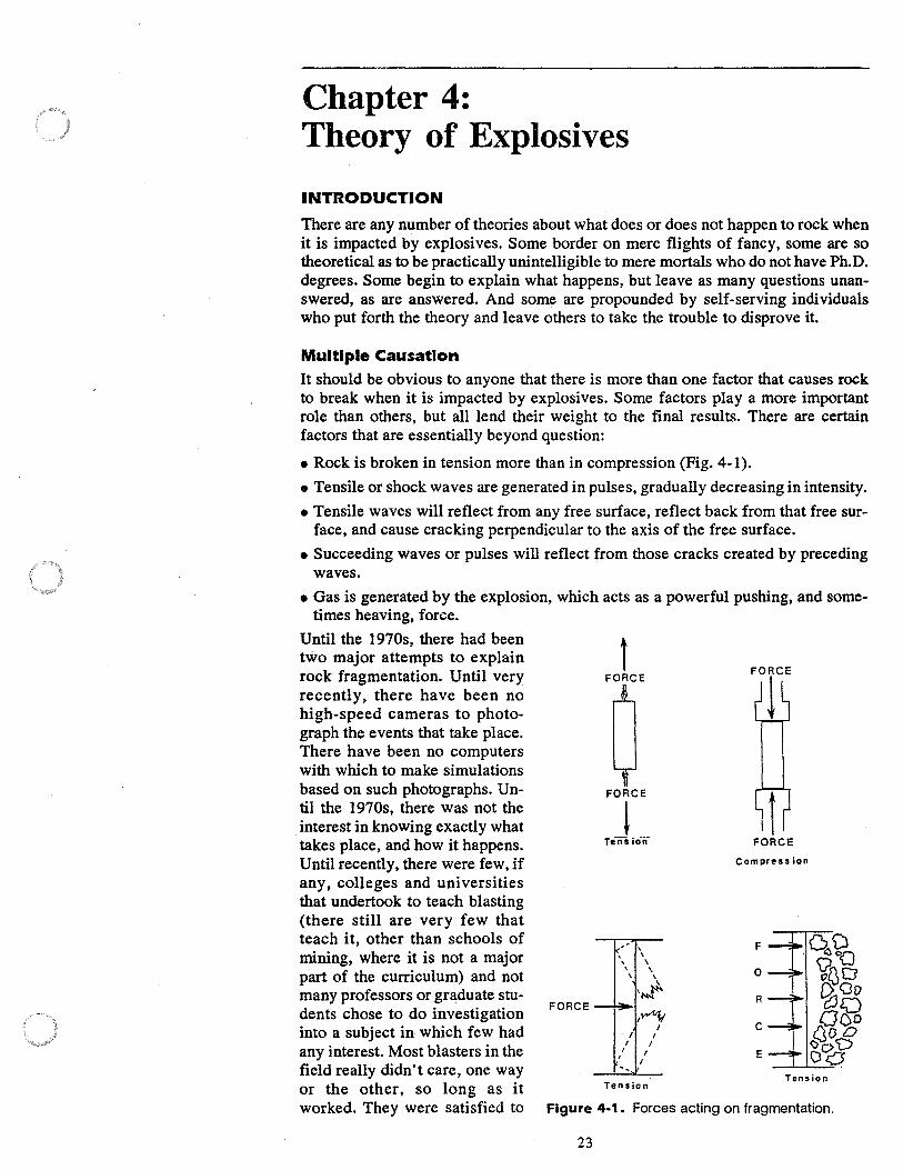
Chapter 4: Theory of Explosives
INTRODUCTION
There are any number of theories about what does or does not happen to rock when it is impacted by explosives. Some border on mere flights of fancy, some are so theoretical as to be practically unintelligible to mere mortals who do not have Ph.D. degrees. Some begin to explain what happens, but leave as many questions unanswered, as are answered. And some are propounded by self-serving individuals who put forth the theory and leave others to take the trouble to disprove it.
Multiple Causation It should be obvious to anyone that there is more than one factor that causes rock to break when it is impacted by explosives. Some factors play a more important role than others, but all lend their weight to the final results. There are certain factors that are essentially beyond question:
• Rock is broken in tension more than in compression (Fig. 4-1).
• Tensile or shock waves are generated in pulses, gradually decreasing in intensity.
• Tensile waves will reflect from any free surface, reflect back from that free surface, and cause cracking perpendicular to the axis of the free surface.
• Succeeding waves or pulses will reflect from those cracks created by preceding waves.
• Gas is generated by the explosion, which acts as a powerful pushing, and some-times heaving, force.
Until the 1970s, there had been two major attempts to explain rock fragmentation. Until very recently, there have been no high-speed cameras to photograph the events that take place. There have been no computers with which to make simulations based on such photographs. Until the 1970s, there was not the interest in knowing exactly what takes place, and how it happens. Until recently, there were few, if any, colleges and universities that undertook to teach blasting (there still are very few that teach it, other than schools of mining, where it is not a major part of the curriculum) and not many professors or graduate stu-
F ORc E dents chose to do investigation into a subject in which few had any interest. Most blasters in the field really didn't care, one way or the other, so long as it
t FORCE
FORCE
i Tens io-n·
- \ \ \
\ \ \ \
\
'~ I~
I I
Tension
I I
I
FORCE
·compress ion
F
0
R
C
E
Tension
worked. They were satisfied to Figure 4-1. Forces acting on fragmentation.
23
24 BLASTING MANUAL
accept what they were told by those whom they thought should know. It is well, however, to review the old theories, happily briefly, to get the feeling of how far we have progressed.
The hydrodynamic theory has been with us almost from the beginning. It remaiu with us still. When things go wrong, fly rock occurs, rock does not break well, boulders are created, or the bottom of the shot can't be excavated short of blasting again. The most typical excuse is "All the gas went out the seams." This one is only just a little less prevalent than,"The rock is no good." The hydrodynamic theory placed gas production at the head of the list of causes for good or bad breakage.
The theory is simplicity itself. The explosives detonate. Gases are produced. The gases push against the rock. The rock breaks from the pressure of all that gas. Simple, direct, and not much thought need be given to anything else.
If the hydrodynamic theory were in fact true and all other mechanisms played only · a small part in rock breakage, all would be well. There would also be a great deal of crushed rock around. Pressure from gases would put the rock in compression. Compressing any material is the act of trying, with force, to make that material smaller. When rock fails in compression at the stress point, the rock is pulverized. What's wrong with the theory? Watch any blast and you can immediately tell that the rock is in tension, being forced out of its position and made larger. Not the individual pieces, but the formation. It bulges, does it not?
The tensile theory of rock breakage came out of some of the first academic attempts to explain what happens. In the laboratories and classrooms of schools of mining, particularly the Rolla School of Mines of the University of Missouri, work on the theory of rock breakage began. Eventually, through several doctoral dissertations, the theory gained acceptance and was even vaguely understood by blasters in the field. What was propounded was basically this: ·
The explosive detonates. Shock ·waves are generated and proceed out to the ./ nearest free face. The waves are then reflected back into the face, putting the rock in tension, causing spalling at the face. Succeeding waves continue the process, traveling out to a less dense material, air, and as one academic put it, "The rock is literally pulled from the face." Nice try. However, if this were true, the finest fragmentation would occur farthest from the borehole at the free face, and the coarsest material would come from the point closest to the borehole. This theory should not be dismissed out of hand. Not yet, and probably not ever.
In fact, there is more than ample scientific proof that reflection at free faces has a great deal to do with overall rock fragmentation. What is wrong is the rock is not pulled from the face, it is pushed, as those who went with, and still go with, the hydrodynamic theory always said it was. But before it is pushed, it must first be broken. Two of the pieces of the puzzle are in place.
The flexural bending or rupture theory came into being in the late 1970s. It proposes that 90 percent of all breakage comes from gas pressure. The rock in front of the borehole acts as a vertical beam and bends because the floor is deeper than the top, and so forth. It is difficult to explain the theory in a short few paragraphs, and there is little need to do so since few people in the field accept this theory as anything approaching what really happens.
The stress wave and gas expansion theory is generally accepted as a relatively simple explanation of very complex mechanisms that are only now being understood. What this theory states is, essentially this:
'>* fi
The detonation produces a series of shock fronts, which rapidly decay. Th..,/ cause cracking from reflection at any free surface, even those that are latent or invisible to the eye. The cracking is perpendicular to (not parallel as stated in the flexural bending theory) the direction of the plane of separation. At the same
CHAPTER 4: THEORY OF EXPLOSIVES 25
time, gases begin to vent through the broken rock,· which, now that it is broken, begins to move from its in situ position. According to "Explosives and Rock Blasting" cited previously, the theory was formulated by Kutter and Fairhurst in 1971 and expanded periodically since.
The main points of interest of the stress wave and gas expansion theory are:
• Neither strain waves nor gas pressure alone is responsible for rock fragmentation.
• Radial cracks originate at the borehole wall.
• Pre-existing cracks would reinitiate under stress, but no new cracks would form in any area occupied by an old crack.
• Presence of a free face favors extension of gas pressurized cracks in that direction.
• In situ stresses affect the direction in which radial cracks travel.
•Fora given borehole size, increase of explosive charge beyond the optimum does not increase fragmentation, but merely throws the material farther.
A very simplified explanation of all of the above is this:
Picture a borehole with a single extremely powerful piston inside. The pointed end of the piston is against one side of the borehole wall, the side toward an open face. The piston is then activated with great force (detonation). The rock is in tension. (See Fig. 4-1.) The piston is trying to make the rock larger by pushing at one point, outward. Some ·breakage occurs at that point.
Now picture an infinite number of those pistons, starting from the bottom, up the borehole, slamming into the rock. If there is a free face, the rock will try to move forward. It will certainly crack. Now the hydraulic oil (gas pressure) that actuated those pistons is rapidly and forcefully pushed into the broken rock, moving the rock away from its original position. At the same time, the shock waves generated by the slamming of this infinite number of pistons causes cracking wherever there is weakness (planes of separation, actual or latent) causing further breakage, along with the primary breakage.
Does It Make Any Difference?
How much of a difference it makes depends upon the individual orientation. For the purposes of blasting, it makes this difference-anyone dealing with blasting should understand what takes place during the blast, just as an aircraft pilot must understand the principles of flight. "When thrust overcomes drag, and lift over-
. comes gravity, flight can take place and be maintained." Do you really wish to fly in an aircraft piloted by someone who doesn't understand that?

26 BLASTING MANUAL
Chapter 5: Uniform Rock Classification System
INTRODUCTION
The medium in which reclamation blasting will be performed is rock. While it is not necessary for a blaster or someone with oversight responsibility for blasting to be a geologist, it is necessary that both be familiar with rock formations and characteristics. The Uniform Rock Classification System is a method of categorizing rock so that informed and realistic decisions about how to best blast that rock can be made.
Douglas Williamson, now-retired engineering geologist for the Willamette National Forest, U.S. Forest Service, designed the system. Using the URCS, it is not really necessary to know the type or name of the rock. As Williamson has said, "You can call it Mabel, Fred, or even Gertrude. The rock doesn't care, and neither should you." The system was developed over many years to define the major strength and behavior parameters of rock without going into the fine details of type classification. What is important are rock characteristics. This author, with considerable help from Mr. Williamson, adapted the system to meet the special requirements of blasters.
The URCS is, in effect, engineering shorthand that can readily define the relevant characteristics of a rock formation. It defines four basic elements of rock mass strength: weathering, mineral grain bonding, planar and linear elements, and unit weight
WEATHERING ELEMENT
The degree of weathering is restricted to chemical weathering. The effect of weathering can be defined by determining its relative loss of cohesion and reduction in unit weight. As with the other three elements, weathering is divided into five categories:
E. Completely decomposed state (CDS) - When the rock material is all remoldable to sand, silt, or clay, or mixtures of two or more sizes. It is what most of us would call "dirt". No blasting is required.
D. Partly decomposed state (PDS) - When the rock material is remoldablc to gravel-size and larger-size rock fragments with or without sand, silt, or clay mixtures. Most PDS rock can be ripped or bladed and needs no blasting.
C. Stained state (STS) - When the rock material shows partial or complete discoloration due to oxidation, but cannot be remolded. The rock samples arc generally shades of yellow or brown and have reduced weight and higher than normal water absorption. The samples appear to be rusted. In fact, they arc rusted in the sense that rust is oxidation.
Since STS rock has lost weight and strength, it can often be ripped or bladed. If it must be blasted, it will normally respond very well to low-velocity, low-density, less-expensive explosives, such as AN-FO, semi-gelatin dynamites, etc.
B. Visually fresh state (VFS) - When the rock is representative of standard quality and not expected to change during excavation. The rock is evaluated with the naked eye. The rock has a uniform color, usually gray, blue, black, etc. Slight discoloration may be found where there are planes of separation in the rock mass.
27
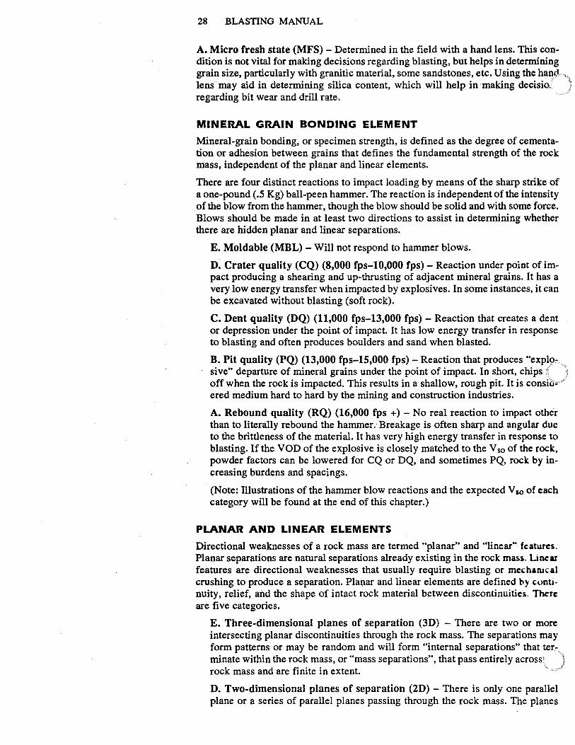
28 BLASTING MANUAL
A. Micro fresh state (MFS) - Determined in the field with a hand lens. This condition is not vital for making decisions regarding blasting, but helps in determining grain size, particularly with granitic material, some sandstones, etc. Using the ha°'ci lens may aid in determining silica content, which will help in ·making decisio. regarding bit wear and drill rate.
MINERAL GRAIN BONDING ELEMENT
Mineral-grain bonding, or specimen strength, is defined as the degree of cementation or adhesion between grains that defines the fundamental strength of the rock mass, independent of the planar and linear elements.
There are four distinct reactions to impact loading by means of the sharp strike of a one-pound ( .5 Kg) ball-peen hammer. The reaction is independent of the intensity of the blow from the hammer, though the blow should be solid and with some force. Blows should be made in at least two directions to assist in determining whether there are hidden planar and linear separations.
E. Moldable (MBL) - Will not respond to hammer blows.
D. Crater quality (CQ) (8,000 fps-10,000 fps) - Reaction under point of impact producing a shearing and up-thrusting of adjacent mineral grains. It has a very low energy transfer when impacted by explosives. In some instances, it can be excavated without blasting (soft rock).
C. Dent quality (DQ) (11,000 fps-13,000 fps) - Reaction that creates a dent or depression under the point of impact. It has low energy transfer in response to blasting and often produces boulders and sand when blasted.
B. Pit quality (PQ) (13,000 fps-15,000 fps) - Reaction that produces 0 explo:::. sive" departure of mineral grains under the point of impact. In short, chips : j off when the rock is impacted. This results in a shallow, rough pit. It is consfo- Y
ered medium hard to hard by the mining and construction industries.
A. Rebound quality (RQ) (16,000 fps +) - No real reaction to impact other than to literally rebound the hammer.· Breakage is often sharp and angular due to the brittleness of the material. It has very high energy transfer in response to blasting. If the VOD of the explosive is closely matched to the V so of the rock, powder factors can be lowered for CQ or DQ, and sometimes PQ, rock by increasing burdens and spacings.
(Note: Illustrations of the hammer blow reactions and the expected V so of each category will be found at the end of this chapter.)
PLANAR AND LINEAR ELEMENTS
Directional weaknesses of a rock mass are termed 0 planar" and 0 linear"' feature,. Planar separations are natural separations already existing in the rock mass. Linear features are directional weaknesses that usually require blasting or mecharucal crushing to produce a separation. Planar and linear elements are defined by continuity, relief, and the shape of intact rock material between discontinuities. There are five categories.
E. Three-dimensional planes of separation (3D) - There are two or more intersecting planar discontinuities through the rock mass. The separations may form patterns or may be random and will form "internal separations" that terminate within the rock mass, or "mass separations", that pass entirely across rock mass and are finite in extent.
D. Two-dimensional planes of separation (2D) - There is only one parallel plane or a series of parallel planes passing through the rock mass. The planes
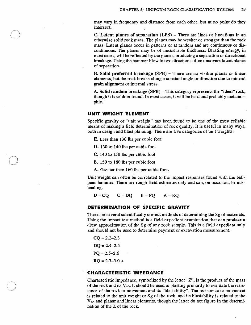
CHAPTER 5.: UNIFORM ROCK CLASSIFICATION SYSTEM 29
may vary in frequency and distance from each other, but at no point do they intersect.
C. Latent planes of separation (LPS) - There are lines or lineations in an otherwise solid rock mass. The planes may be weaker or stronger than the rock mass. Latent planes occur in patterns or at random and are continuous or discontinuous. The planes may be of measurable thickness. Blasting energy, in most cases, will be reflected by the planes, producing a separation or directional breakage. Using the hammer blow in two directions often uncovers latent planes of separation.
B. Solid preferred breakage (SPB) - There are no visible planar or linear elements, but the rock breaks along a constant angle or direction due to mineral grain alignment or internal stress.
A. Solid random breakage (SPB) -This category represents the "ideal" rock, though it is seldom found. In most cases, it will be hard and probably metamorphic.
UNIT WEIGHT ELEMENT
Specific gravity or "unit weight" has been found to be one of the most reliable means of making a field determination of rock quality. It is useful in many ways, both in design and blast planning. There are five categories of unit weights:
E. Less than 130 lbs per cubic foot
D. 130 to 140 lbs per cubic foot
C. 140 to 150 lbs per cubic foot
B. 150 to 160 lbs per cubic foot
A. Greater than 160 lbs per cubic foot.
Unit weight can often be correlated to the impact responses found with the ballpeen hammer. These are rough field estimates only and can, on occasion, be mis-leading. ·
D=CQ C=DQ B=PQ A=RQ
DETERMINATION OF SPECIFIC GRAVITY
There are several scientifically correct methods of determining the Sg of materials. Using the impact test method is a field-expedient examination that can produce a close approximation of the Sg of any rock sample. This is a field expedient only and should not be used to determine payment or excavation measurement.
CQ = 2.2-2.3
DQ= 2.4-2.5
PQ=2.5-2.6
RQ = 2.7-3.0 +
CHARACTERISTIC IMPEDANCE
Characteristic impedance, symbolized by the letter "Z", is the product of the mass of the rock and its V so, It should be used in blasting primarily to evaluate the resistance of the rock to movement and its "blastability". The resistance to movement is related to the unit weight or Sg of the rock, and its blastability is related to the V so and planar and linear elements, though the latter do not figure in the determination of the Z of the rock.
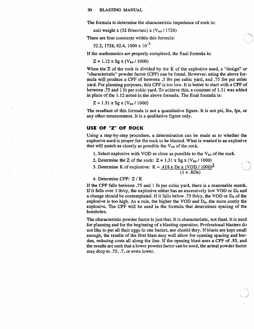
30 BLASTING MANUAL
The formula to determine the characteristic impedance of rock is:
unit weight x (32 ft/sec/sec) x (Vso / 1728)
There are four constants within this formula:
32.2, 1728, 62.4, 1000 X 10"3
If the mathematics are properly completed, the final formula is:
Z = 1.12 X Sg X (Vso / 1000)
When the Z of the rock is divided by the K of the explosive used, a "design .. or "characteristic" powder factor (CPF) can be found. However, using the above formula will produce a CPF of between .5 lbs per cubic yard, and .75 lbs per cubic yard. For planning purposes, this CPF is too low. It is better to start with a CPF of between .75 and l lb per cubic yard. To achieve this, a constant of 1.31 was added in place of the 1.12 noted in the above formula. The final formula is:
Z = 1.31 X Sg X (Vso / 1000)
The resultant of this formula is not a quantitative figure. It is not psi, lbs, fps, or any other measurement. It is a qualitative figure only.
USE OF HZ" OF ROCK
Using a step-by-step procedure, a determination can be made as to whether the explosive used is proper for the rock to be blasted. What is wanted is an explosive that will match as closely as possible the V so of the rock.
1. Select explosive with VOD as close as possible to the V so of the rock.
2. Determine the Z of the rock: Z = 1.31 x Sg x (V so / 1000)
3. Determine K of explosive: K = .418 x Dex (VOD / 1000~ (1 + .8De)
4. Determine CPF: Z / K
If the CPF falls between .75 and 1 lb per cubic yard, there is a reasonable match. If it falls over 1 lb/cy, the explosive either has an excessively low VOD or De and a change should be contemplated. If it falls below . 7 5 lb/cy, the VOD or De of the explosive is too high. As a rule, the higher the VOD and De, the more costly the explosive. The CPF will be used in the formula that determines spacing of the boreholes.
The characteristic powder factor is just that. It is characteristic, not final. It is used for planning and for the beginning of a blasting operation. Professional blasters do not like to put all their eggs in one basket, nor should they. If blasts are kept small enough, the results of the first blast may well allow for opening spacing and burden, reducing costs all along the line. If the opening blast uses a CPF of .85, and the results are such that a lower powder factor can be used, the actual powder factor may drop to .75, .7, or even lower.
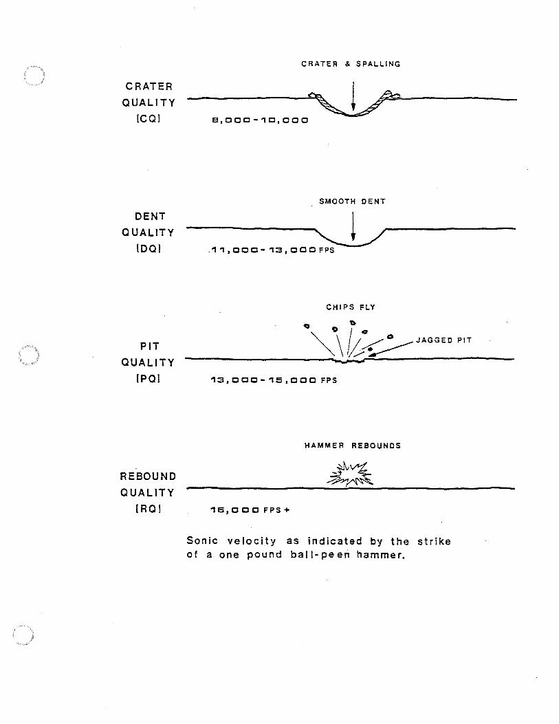
CRATER
QUALITY
!COi
DENT QUALITY
IDOi
PIT
QUALITY
(PO)
REBOUND QUALITY
[RO I
CRATER & SPALLING
--~.___-e,ccc-10,ccc
SMOOTH DENT
----0----.11, CCC - 1::3, CCC FPS
CHIPS FLY
c:a Q /~o "'- -\ / /~
0___..- JAGGED PIT
""\ I/?~
1::3,CCC-15,CCC FPS
HAMMER REBOUNDS
16,000 FPS+
Sonic velocity as indicated by the strike of a one pound ball-peen hammer.
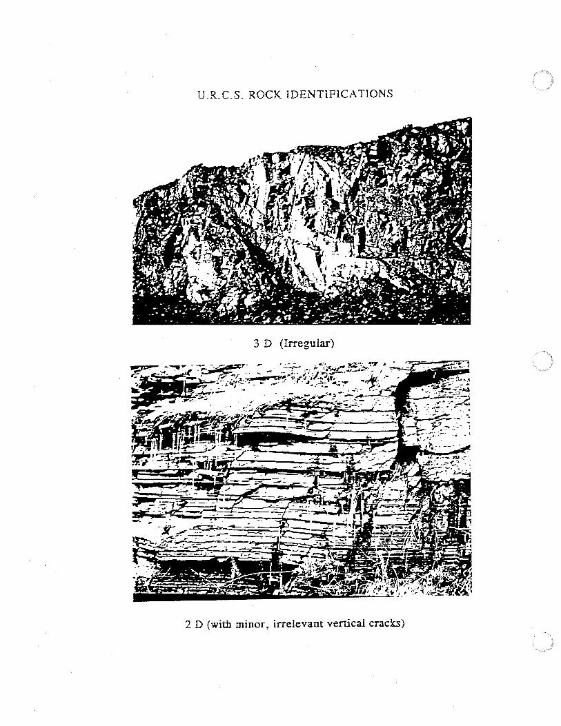
U .R. C.S. ROCK lDENTIFlCA TIO NS
3 D (Irregular)
2 D (with minor, irrelevant vertical cracks)
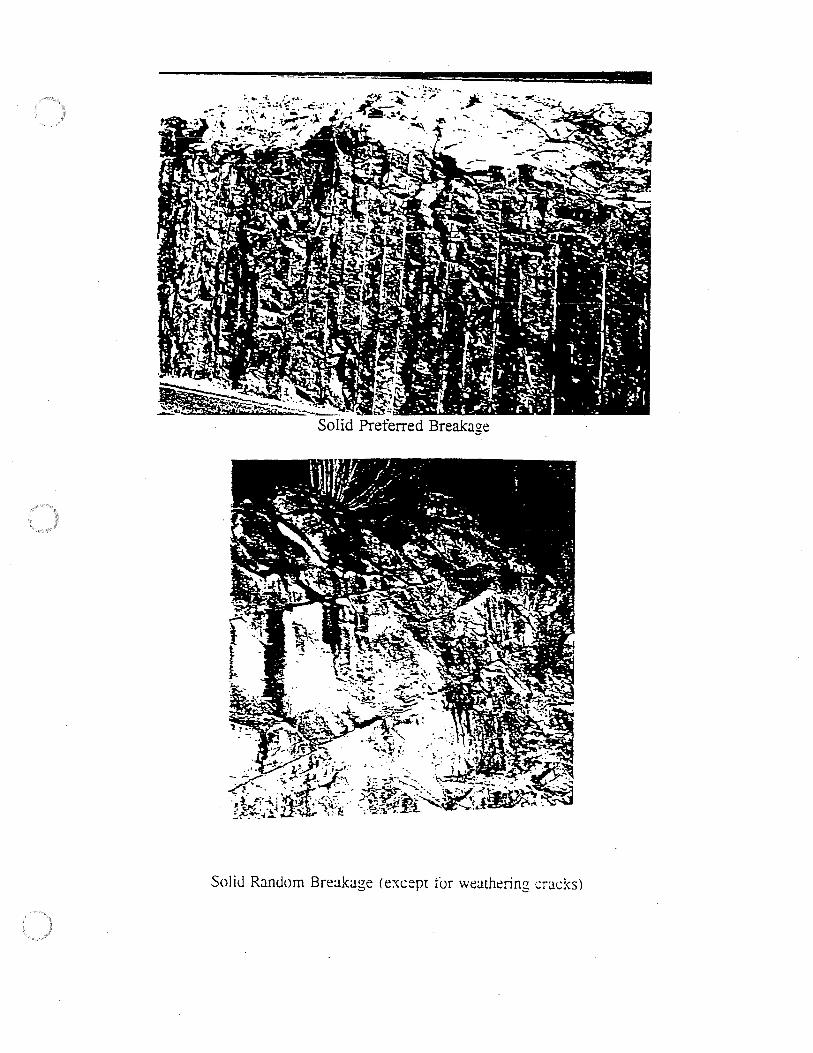
----·--- --- .
Solid Random Breakage (except for weathering crac!<s)

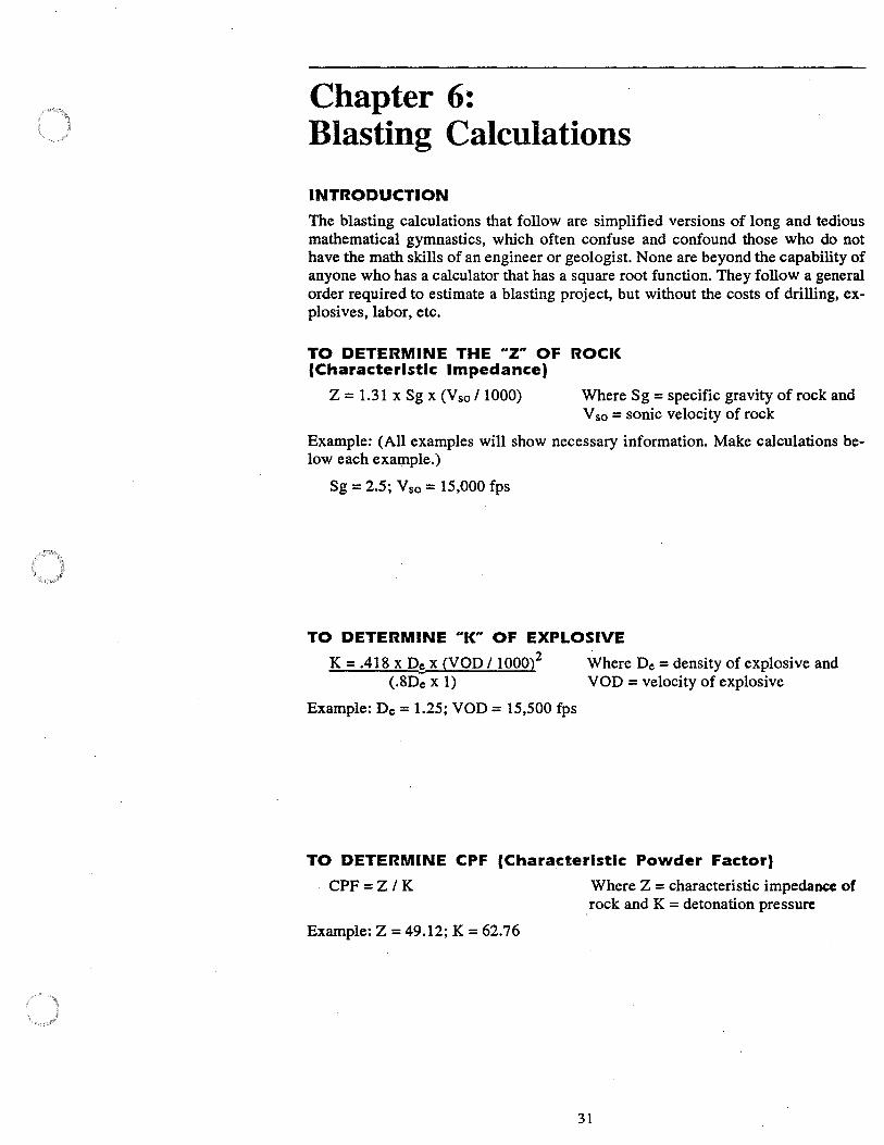
Chapter 6: Blasting Calculations
INTRODUCTION
The blasting calculations that follow are simplified versions of long and tedious mathematical gymnastics, which often confuse and confound those who do not have the math skills of an engineer or geologist. None are beyond the capability of anyone who has a calculator that has a square root function. They follow a general order required to estimate a blasting project, but without the costs of drilling, explosives, labor, etc.
TO DETERMINE THE uz" OF ROCK (Characteristic Impedance)
Z = 1.31 x Sg x (V so/ 1000) Where Sg = specific gravity of rock and V so = sonic velocity of rock
Example: (All examples will show necessary information. Make calculations below each example.)
Sg = 2.5; Vso = 15,000 fps
TO DETERMINE UK" OF EXPLOSIVE
K = .418 x Ds x (VOD 1100022
(.8De X 1)
Example: De = 1.25; VOD = 15,500 fps
Where De = density of explosive and VOD = velocity of explosive
TO DETERMINE CPF (Characteristic Powder Factor)
CPF =Z I K
Example: Z = 49.12; K = 62.76
Where Z = characteristic impedance of . rock and K = detonation pressure
31
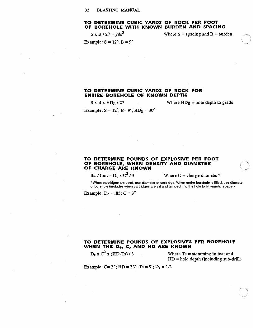
32 BLASTING MANUAL
TO DETE.RMINE CUBIC YARDS OF ROCK PER FOOT OF BOREHOLE WITH KNOWN BURDEN AND SPACING
S x B / 27 = yds3
Example: S = 12'; B = 9'
Where S = spacing and B = burden
TO DETERMINE CUBIC YARDS OF ROCK FOR ENTIRE BOREHOLE OF KNOWN DEPTH
S x Bx HDg /27 Where HDg = hole depth to grade
Example: S = 12'; B= 9'; HDg = 30'
TO DETERMINE POUNDS OF EXPLOSIVE PER FOOT OF BOREHOLE, WHEN DENSITY AND DIAMETER OF CHARGE ARE KNOWN
lbs / foot = De x c2 / 3 Where C = charge diameter*
* When cartridges are used, use diameter of cartridge. When entire borehole is filled, use diameter of borehole (includes when cartridges are slit and tamped into the hole to fill annular space.)
Example: De= .85; C = 3"
TO DETERMINE POUNDS OF EXPLOSIVES PER BOREHOLE WHEN THE De, C, AND HD ARE KNOWN
De x c2 x (HD-Ts) / 3 Where Ts = stemming in feet and HD = hole depth (including sub-drill)
Example: C= 3"; HD= 33'; Ts= 9'; De= 1.2
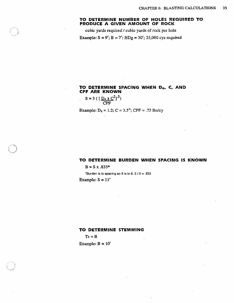
CHAPTER 6: BLASTING CALCULATIONS 33
TO DETERMINE NUMBER OF HOLES REQUIRED TO PRODUCE A GIVEN AMOUNT OF ROCK
cubic yards required / cubic yards of rock per hole
Example: S = 9'; B = 7'; HDg = 30'; 25,000 cys required
TO DETERMINE SPACING WHEN De, C, AND CPF ARE KNOWN
S = 3 ( [ J2c X C2]'
5)
CPF
Example: De= 1.2; C = 3.5"; CPF = .75 lbs/cy
TO DETERMINE BURDEN WHEN SPACING IS KNOWN
B = S x .833*
*Burden is to spacing as 5 is to 6. 5 / 6 = .833
Example: S = 11'
TO DETERMINE STEMMING
Ts=B
Example: B = 10'

34 BLASTING MANUAL
TO DETERMINE SUB-DRILL
SD = .3-.5 of spacing
Example: S = 12'
TO DETERMINE TOTAL FOOTAGE OF DRILLING REQUIRED FOR GIVEN AMOUNT OF ROCK REQUIRED
total cubic yards required / S x B x HDg number of holes x HD including sub-drill
Example: cys required= 12,000; S = 10'; B = 8'; Hdg = 25'; SD= .3
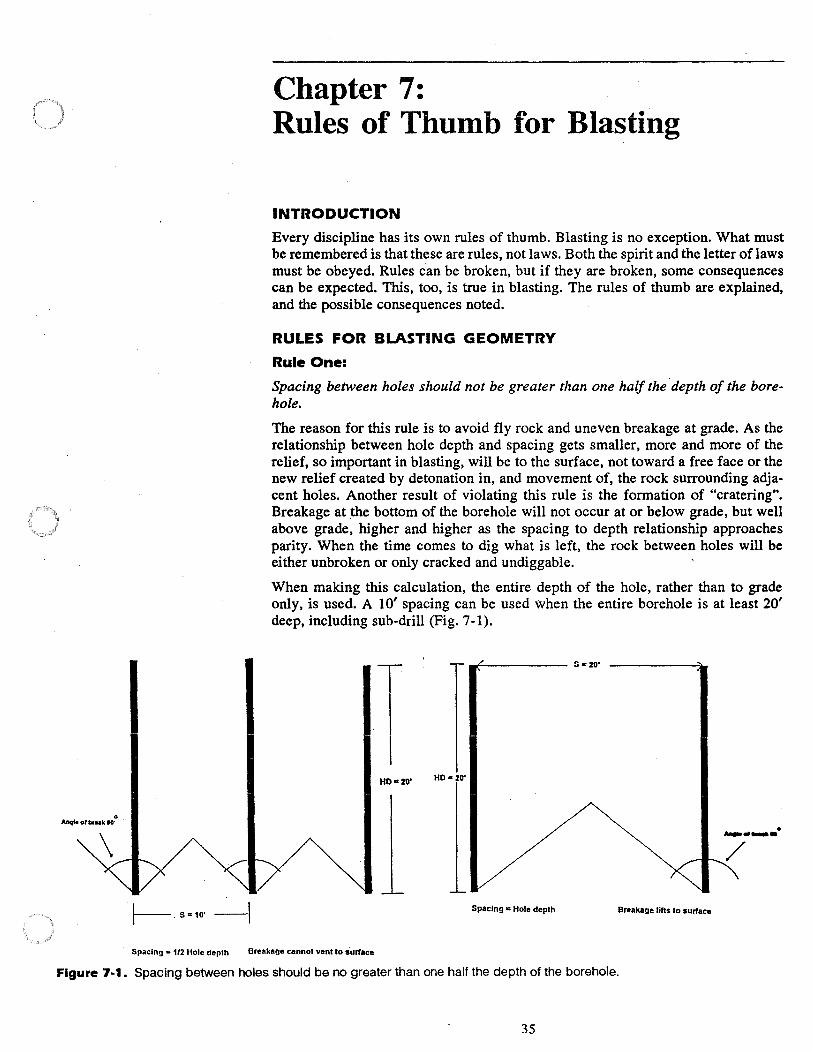
t---. S=10' -I
Chapter 7: Rules of Thumb for Blasting
INTRODUCTION
Every discipline has its own rules of thumb. Blasting is no exception. What must be remembered is that these are rules, not laws. Both the spirit and the letter of laws must be obeyed. Rules can be broken, but if they are broken, some consequences can be expected. This, too, is true in blasting. The rules of thumb are explained, and the possible consequences noted.
RULES FOR BLASTING GEOMETRY
Rule One:
Spacing between holes should not be greater than one half the depth of the borehole.
The reason for this rule is to avoid fly rock and uneven breakage at grade. As the relationship between hole depth and spacing gets smaller, more and more of the relief, so important in blasting, will be to the surf ace, not toward a free face or the new relief created by detonation in, and movement of, the rock surrounding adjacent holes. Another result of violating this rule is the formation of 0 cratering". Breakage at the bottom of the borehole will not occur at or below grade, but well above grade, higher and higher as the spacing to depth relationship approaches parity. When the time comes to dig what is left, the rock between holes will be either unbroken or only cracked and undiggable.
When making this calculation, the entire depth of the hole, rather than to grade only, is used. A 1 O' spacing can be used when the entire borehole is at least 20' deep, including sub-drill (Fig. 7-1).
HO• 20"
Spacing • Hole depth Breakage lifts to surface
• ._.,,_.
Spacing = 1/2 Hole depth Breakage cannot vent to surface
Figure 7-1. Spacing between holes should be no greater than one half the depth of the borehole.
35
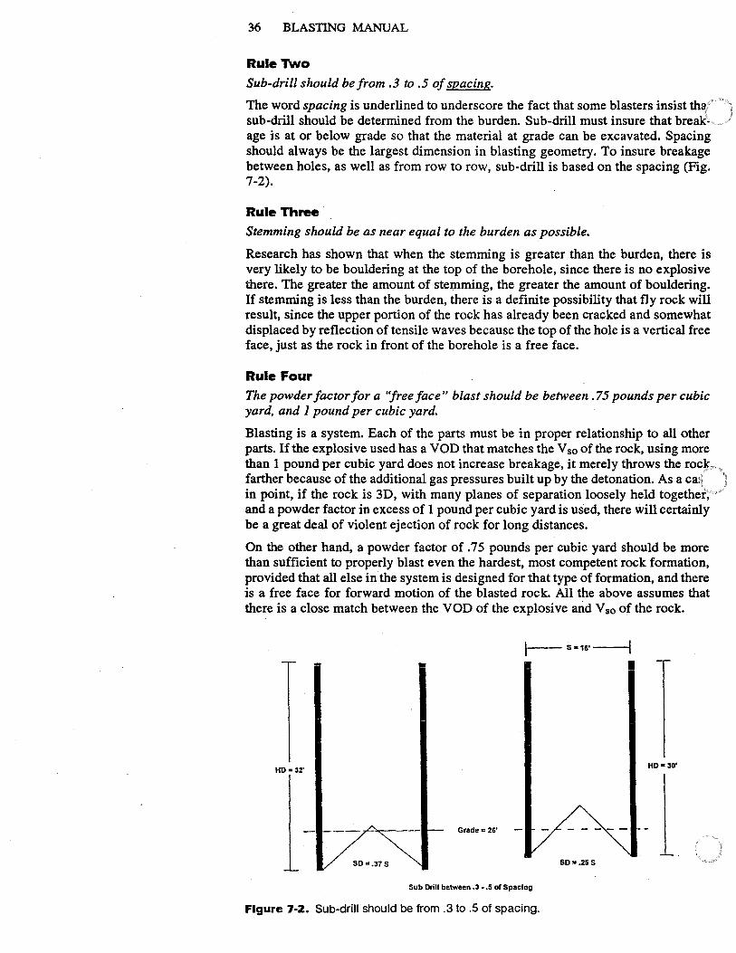
36 BLASTING MANUAL
Rule Two
Sub-drill should be from .3 to .5 of spacing.
The word spacing is underlined to underscore the fact that some blasters insist tha sub-drill should be determined from the burden. Sub-drill must insure that breakage is at or below grade so that the material at grade can be excavated. Spacing should always be the largest dimension in blasting geometry. To insure breakage between holes. as well as from row to row, sub-drill is based on the spacing (Fig. 7-2).
Rule Three Stemming should be as near equal to the burden as possible.
Research has shown that when the stemming is greater than the burden, there is very likely to be bouldering at the top of the borehole, since there is no explosive there. The greater the amount of stemming, the greater the amount of bouldering. If stemming is less than the burden, there is a definite possibility that fly rock will result, since the upper portion of the rock has already been cracked and somewhat displaced by reflection of tensile waves because the top of the hole is a vertical free face, just as the rock in front of the borehole is a free face.
Rule Four The powder factor for a ''free face" blast should be between . 75 pounds per cubic yard, and 1 pound per cubic yard.
Blasting is a system. Each of the parts must be in proper relationship to all other parts. If the explosive used has a VOD that matches the V so of the rock, using more than 1 pound per cubic yard does not increase breakage, it merely throws the rock farther because of the additional gas pressures built up by the detonation. As a ca: in point, if the rock is 30, with many planes of separation loosely held together, and a powder factor in excess of 1 pound per cubic yard is used, there will certainly be a great deal of violent ejection of rock for long distances.
On the other hand, a powder factor of . 7 5 pounds per cubic yard should be more than sufficient to properly blast even the hardest, most competent rock formation, provided that all else in the system is designed for that type of formation, and there is a free face for forward motion of the blasted rock. All the above assumes that there is a close match between the VOD of the explosive and V so of the rock.
I- S •16' ---{
HD• 32' HD• 30'
Grade c 26'
SD =.37 S SD ... 25S
Sub Drill between .3 •• 5 of Spacing
Figure 7-2. Sub-drill should be from .3 to .5 of spacing.

CHAPTER 7: RULES OF THUMB FOR BLASTING 37
In those instances where there is no free face (vertical) available (called a "sink shot" or "sinking cut"), a powder factor of no less than 1 pound per cubic yard in the case of unconsolidated rock and 1.25 pounds per cubic yard for more massive formations is required. Again, all the other parts of the system must be in place for any successful, well-controlled blast.

38 BLASTING MANUAL
Chapter 8: Delay Systems
INTRODUCTION
To attempt to detail and explain the uses of every possible delay system for any given circumstance would be an exercise in futility. To properly use delay systems the blaster must use imagination, understand certain principles, and .. read the rock". To simplify the matter, it is best to work with need-to-know information and to design the delay system according to what delays are available, what is to be accomplished, and what the rock demands.
Rectangular vs. Square Patterns Blasters, like most technicians, tend to find one method of doing something and then stay with that method because it works, because good results have come from using it, and because staying with the tried and true is easy. Many blasters use a square pattern and still use delays. A square pattern is when the drill pattern holds the burden equal to the spacing. With a square pattern, there is equal distribution of explosives in the rock mass. All holes are equidistant from each other. All are loaded very much the same. Not a bad way to do things-at least so far as the equal distribution of explosives is concerned. However, once delays are added into the equation, things change rapidly.
Research has shown that when spacing and burden are equidistant, the detonation . of the first borehole.or boreholes causes cracking systems to develop that actually break from hole to hole. As a rule, detonation of a single hole toward a free face will cause an angle of break of about 100 degrees. Since the adjacent boreholes are planes of separation, tensile waves will also travel in the direction of those adjacent holes, including those behind the first row (Fig. 8-1).
As the spacing is increased in relationship to the burden, the cracking toward adjacent holes is reduced, since the free face is now .. the path of least resistance". At the point when the spacing to burden relationship reaches a ratio of 6 to 5, there is
. little or no cracking toward adjacent holes or to the rear, even though the.hole directly behind the hole that has detonated is the same distance from that hole as is the free face to the first hole. This phenomenon has yet to be fully explained (Fig. 8-2). Increasing the spacing to burden ratio does not change the cracking pattern.
Principle 1 : When ever delays are used, the drill pattern should be rectangular, with a spacing to burden relationship of at least 6:5 or B = S x .833.
Planned Burden vs. Actual Burden Patterns are drilled with a specified burden and spacing. However, assuming that delays are used, once a borehole has detonated and the rock has moved from its in-situ position, another free face or path of least resistance has been created. This is called the "actual" burden.
There is no doubt that the first borehole to detonate will affect the rock directly in front of it (planned burden) and break on the 100 degree angle, depending upon the rock formation. (The angle may vary from 90 degrees to as much as 110 degrees.) Adjacent holes, however, now have a new free face-the actual burden. When the spacing to burden ratio is 6:5, the new free face is found to be just about half that of the planned burden (Fig. 8-2). Tests have shown that when the spacing is twice
39
40 BLASTING MANUAL
Free Face
I
Spacing = Burdeu
- e e Figure 8-1. As a rule, detonation of a single hole toward a free face will cause an angle of break of about 100 degrees.
the burden, or when S = 2 and B = 1, optimum fragmentation is attained. This has been established and often mentioned in technical literature. However, too often some blasters assume that what is meant is the planned burden. A planned spacing and burden ratio of 2: I will often produce a sawtooth effect at the new free face, which creates boulders in between boreholes.
Principle 2: No two holes side by side in any di- . rection should detonate on the same period of delay.
This principle is outlined above. Delays should be used sequentially, with sufficient delay time between them to allow for rock cracking and move
...,?:,,':
• •
Free Face
' . ., -- __ :·_~
• • Figure 8·2. At the point when the spacing to burden relationship reaches a ratio of 6 to 5; there is little or no cracking toward adjacent holes or to the rear, even though the hole directly behind the hole that has detonated is the same distance from that hole as is the free face to the first hole.
ment. When adjacent holes detonate at the same time, there is no delay. If the pattern is rectangular, the angle of breakage changes, and less fine fragmentation can be expected, requiring closer burdens and spacings. Closer burden and spacing increases the powder factor, which may well, and probably will, create fly rock .
.. Scatter" In Delay Cap Timing
From the very beginning, manufacturers of delay blasting caps were aware that the · timing of the caps was not as accurate as blasters were led to believe. It was not until 1978 that Stephen Winzer, Ph.D., of the University of Maryland proved be-
CHAPTER 8: DELAY SYSTEMS 41
yond doubt that there is, indeed, scatter in delay timing. In the higher periods, the scatter may be as much as one or even two delay periods out of order. The problems that arise from cap scatter are many. If there is not sufficient timing between rows of holes, a hole in a back row may detonate before the hole in front of it. In this event, the second hole now has double the planned burden to move. In addition, the detonation of that hole will in all probability cause cracking of rock around the hole in the preceding row. The results are always violent pluming of gases, throw into the air of rock from both holes, and a complete change in the direction of breakage in all adjacent holes. For that early firing hole, there is no free face except the surface. As it breaks to the surface, it will affect all adjacent holes, including those to the rear.
Principle 3:
Timing between rows should be no less than JO millisecond per foot of burden.
There has long been controversy as to how much delay is enough and how much is too much. A two-year study of the effect of delay timing on fragmentation was undertaken on the Coquihalla Highway Project, in British Columbia, Canada. The research proved, to the amazement of those of us who were conducting the work, that a minimum of 10 milliseconds per foot of burden is required for good fragmentation with the lowest powder factor, which means extended spacing and burden, and as much as 15 milliseconds per foot of burden as an optimum. It was also found that by manipulating the timing between rows of holes and limiting the number of rows to no more than three, the actual profile of the muck pile can be adjusted. This has interesting possibilities for reclamation blasting. If a high profile is wanted, a decrease in timing between rows will achieve the desired result. If a low profile is needed, an increase of timing between rows to as much as 25 milliseconds per foot of burden will do the job.
Principle 4:
Just as there should be no less than JO milliseconds between rows of holes, so too there should be no less than JO ms between holes.
Holding sufficient delay time between holes and rows of holes not only provides the best fragmentation, but even more important, will overcome the deleterious effect of cap scatter. Blasting caps are now mostly made in 25 ms increments. If the burden between rows is 10 feet and the delay time is held to 10 ms per foot of burden, there will be a spread of 100 ms between rows, which is four periods of delay. Even the most poorly manufactured blasting caps will not scatter that much.
In defense of the manufacturers of blasting caps, it must be stated that the blasting caps manufactured in the U.S., Canada, and the U.K. are extremely accurate, considering the cost and the fact that they must be accurate within thousandths of a second. (This author has used caps manufactured in four different countries other than those noted, and none come even close in quality control, and all were far more expensive.) The argument regarding scatter is not that it occurs, but that for years, manufacturers either denied the fact or simply ignored it.
Delay Patterns
There are any number of preferred delay-patterns. There is the ubiquitous "V" cut, the echelon, the corner shot, etc. These are shown in Figures 8-3 through 8-5 below:
42 BLASTING MANUAL
Solid
. ,, 10 .,/' 9
/ ./ 8
~"*'W~~'W'W'®'Yitfe1'il($©1'rtttil/Bfitt.:ia~ Free Face
Solid
Figure 8-3. V-cut millisecond delay pattern. Numbers by holes denote firing order. (Reprinted from Atlas Powder Company, 1987, Explosives and Rock Blasting, figure 9.5.)
Solid
Solid
. •---.. ----•---•----•---------.... . 6 .,/ 5 5 5 5 5 5 5 ', 6 .,, '
/ ' • ~---------•----•---•---+----- .... 5 / 4 4 4 4 4 4 4 ', 5 .,, ' ./ ·---------•----.----•----•----- 'e Solid 4 /.,,3 3 3 3 3 3 3', 4
.,,/ ', " ·--------·----•---------•-----, 'e 3 .,,/ 2 2 2 2 2 2 2 ', 3
.,,"" ' •"" •----·--------•----•----•----• 'e 2 1 1 1 1 1 1 1 2
Free Face -
Figure 8-4. Hole delayed row for row. (Reprinted from Atlas Powder Company, 1987, Explosives and Rock Blasting, figure 9.9.)
CHAPTER&: DELAYSYSTEMS 43
300 275 250 225 200 175 150 125
Solid • • • • • • • • 250 225 200 175 150 125 100 75 • • • • • • • • 250 225 200 175 125 100 75 50 • • • • • • • • 225 175 150 125 100 75 50 25 • • • • • • • • Free Face
Figure 8-5. Millisecond pattern as an echelon shooting to a corner. (Reprinted from Atlas Powder Company, 1987, Explosives and Rock Blasting, figure 9.6.)
Free Face
• • • • • • 25 25 25 50 50 50 75 • • • • • • 75 75 75 100 100 100 125 • • • • • • • 125 125 125 150 150 150 175
• • • • • • • 175 175 175 225 225 225 300 Solid • • • • • • • 250 250 250 300 300 300 350
Figure 8-6. Millisecond pattern shooting to a corner. (Reprinted from Atlas Powder Company, 1987, Explosives and Rock Blasting, figure 9.7.) ·
Free Face
• • • • • • • • • • • 325 275 225 200 175 150 125 100 75 50 25
• • • • • • • • • • • 350 300 250 225 200 175 150 125 100 75 10 • • • • • • • • • • • 375 300 275 250 225 200 175 150 125 100 75
• • • • • • • • • • • 400 325 300 275 250 225 200 175 150 125 100
• • • • • • • • • • • Solid 425 375 325 300 275 250 225 200 175 150 125
• • • • • • • • • • • 475 425 400 375 350 325 300 275 250 200 175
Figure 8-7. Millisecond pattern shooting to a corner. (Reprinted from Atlas Powder Company, 1987, Explosives and Rock Blasting, figure 9.8.)

44 BLASTING MANUAL

Chapter 9: Initiation Systems
INTRODUCTION
There are two types of initiation systems: electric and non-electric. By definition, an initiation system is that which initiates or starts the process, whatever it may be. The same is true for blasting.
The electric initiation system consists of leg wires, two single-strand copper wires that are connected to a blasting cap, which may or may not have a delay element inside. There is an electric match, which heats up when electricity is applied to it. This heat sets off a primary explosive, which in turn initiates the base charge, which in tum initiates the explosive charge in the borehole ( or wherever else that charge is).
The non-electric initiator uses either a low-energy detonating cord (sometimes called Detaline, or some such thing) that detonates at high velocity (23,000-25,000 fps) but has few grains per foot of cord or a reactive powder that has been applied to the inside of a thin plas-tic tube to which a blasting cap is crimped. Both have millisecond-delay capabilities.
Electric blasting caps Electric blasting caps have been somewhat described earlier. Figure 9-1 shows how they are made.
The most important feature of the cap is the delay element. It is this part of the cap that actually creates the delay time between when the electricity reaches the cap, and when the cap detonates. It would seem that there could be no misunderstanding about how the delay timing is accomplished. It is hard to believe that there are those among us, far fewer now than in only a. few years past, who think that the length of the wire attached to a cap has some delay in it. There are still those who will not connect a cap with 6 feet of wire to a cap with 40 feet of wire because there will be a dif-
Polyethylene Legwlre
Non-conductive Sleeve
Primer Charge
Crimp & Sealing
Figure 9-1. Masterdet (MS) Electric Detonator. (Reprinted from Atlas Powder Company, 1987, Explosives and Rock Blasting, figure 6.13.)
45
Figure 9-3. Masterdet Twinplex (MS) Electric Detonators. (Reprinted from Atlas Powder Company. 1987, Explosives and Rock Blasting, figure 6.16.)
46 BLASTING MANUAL
Figure 9-2. Masterdet (MS) Electric Detonators. (Reprinted from Atlas Powder Company, 1987, Explosives and Rock Blasting, figure 6.15.)
ference in the delay and the resistance. There will certainly be a difference in the resistance. All of about .7 ohms, or thereabout (Figs. 9-2, 9-3).
Leg wires range in length from 4 feet long to as much as 150 feet. The caps wi long leg wires are usually inserted into a reel, onto which the wires are wouni;.. These are not used very often except for seismic blasting and exceptional projects. Most quarries and open pit mines are limited to face heights of about 45 feet.
The length of the blasting cap has no relationship to the delay period. It is true that the longer-period delays are often longer than the shorter-period delay caps, but not necessarily.
The color of the leg wires has no particular meaning. There is no positive or negative involved. Except for leg wires in excess of about 80 feet (it varies from manufacturer to manufacturer), the leg wires are different colors. ICI cap wires are usually orange and yellow. IRECO cap wires, green and yellow, etc. There is one rule regarding the color of the wires that should be observed:
Always wire caps color-to-color. There is no electrical reason for this rule. However, when wiring caps one to another to complete a series circuit, if the wires are connected color to color it makes the wiring process easy and is a way to insure that all caps are in the circuit. If there are an even number of caps in the circuit, the last two wires remaining after all caps are wired into a series will be the same color. If there are an odd number of caps in the series, the two remaining leg wires will be different colors. It is the number of caps that is important, not the number of holes, since there is always the possibility that there will be more than one cap in a given borehole if the holes are "decked". A decked borehole is one that has a primed charge at the bottom, a "deck" of stemming material, then another primed charge, then stemming material at the top. Some boreholes may have as many as three or four decks, depending up the circumstances.
CHAPTER 9: INITIATION SYSTEMS 47
Blasting Machines There are three types of blasting machines: (1) T-bar, (2) condenser discharge, and (3) sequential timer.
T-bar blasting machines are familiar to most people through movies and pictures . . They work on the magneto principle. A T-bar blasting machine looks like a rectangular box with a ''T" coming out of the top. There are two wing-nuts attached, to which lead lines are connected. It has been referred to, facetiously of course, as the "John Wayne" box. The raised handle is slammed down sharply and quickly, which drives a magneto to produce electric current. These are now more collectors items than working tools of the trade.
Capacitor discharge (condenser) blasting machines are operated using dry cell batteries to active one or more capacitors, which, when the button is pushed or the switch thrown, sends an electric charge through the lead wires. The charge is generally in the range of 440 volts. Amperage depends upon the resistance. All CD blasting machines have a plate or decal permanently affixed that indicates the capacity of the machine. It will state that the machine will detonate a given number of blasting caps, each with a stated resistance, in series, in series-parallel, or parallel. Most CD blasting machines warn against the use of straight parallel circuits since they require a great deal more amperage than most CD machines produce.
Sequential blasting machines are relatively new on the scene. This is a blasting machine that through a circuit board can initiate 10 separate circuits, one after the other (Figs. 9-4, 9-5).
These machines are especially valuable when a great number of caps are involved. The circuitry is complicated, and great care must be exercised to insure that no wires are cut as each circuit detonates and causes rock movement. Improper use of the equipment will very likely cause a rather impressive misfire. Whole series may fail to fire if one wire is cut. To explain the method of calculating the circuits, the wiring thereof, and the means of making all the connections is more than can be done in this manual. To familiarize oneself with the use of the sequential blasting machine, the manufacturers recommendations should be followed. Another source of excellent information is chapter 9, pages 245 through 277 in the aforementioned "Explosives and Rock Blasting" published by ICI, USA, Dallas, Texas. For blasters, the advice is "read the instructions, before all else fails" since failure can be devastating. For those with oversight responsibilities, it is best to leave the whole matter in the hands of those who should know how to use the equipment. Sequential blasting machines are a marvelous advance in delay blasting, but like all tools, they must be used properly.
Electrical Calculations This manual is not meant to fully train blasters in electric theory or mathematics. What follows should suffice for field work and for an understanding of what to look for and how to know if things are proper or not.
Series circuits are the most common connections made in blasting (Fig. 9-6). Connections are made as shown in the figure.
To calculate the total resistance in a series circuit, simply add the resistance in each cap. Most electric blasting caps have a resistance of about 2.5 ohms. In mathematical terms, the total resistance in a series circuit is:
RT= R1 + R2 + R3 ......... etc.
The total resistance in a series with 10 caps, at 2.5 ohms each is 25 ohms.
Since most CD blasting machines will detonate 50 caps of 2 ohms each, no more than 100 ohms should be in any series. This information is on the plate or decal
48 BLASTING MANUAL
mentioned earlier. With that in mind, the full capacity of the blasting machine should not be used. If the series contains 50 caps at 2.5 ohms each, the total resistance is 125 ohms. There is usually about 5 ohms in the lead line, bringing the totaJ. to 130 ohms. If this circuit is fired there is a good possibility that one or more ca1 in the circuit will fail to detonate, resulting in a dangerous, time consuming, ano very, very embarrassing misfire. The solution, of course, is the parallel-series circuit.
Parallel-series circuits are used when series circuits exceed the capacity of the blasting machine for series circuits (Fig. 9-6).
To calculate the total resistance in a parallel circuit use the formula:
c.-,- .... - .. ~-- -- 4111 ... 1 ... 1• ... ...,_ -1 ~ --~-..... --., ..... .c lli-.a....1.-... .:-.......... .
DANGER - HIGH VOLT AGE - SHOCK HAZARD ~ • ..... ...,,....,_Tll,t,f'M,QfQAftll ...... ...._.-..nw.~ J. -- L .. - In- --• ,,_ ,-., ,._ - .. , .. ., ~--• , .. """' ........ _.., --"""·- ....... -•a. ...... ,1 ... _ --· 1 .... ,. .. ..,•"-••Ju•"-"- .,.. ... mam-.n-N.....,,...;.c.aa.Tn. .. --··--- ........................ -·--"- .. ·-···"-). '!::.!: =~ =~1::·· - -- ··-···· "'·-......... - ...... .. I, MU_,,__,,._.,..CUM._-.r.~M"IIUJl~f'Oll.lt'lux.u,r:a
~: ~. ~.:i .. =._-,·;..-;.·::.-:.-:;~~-:-::.:::: :lu~'!.."':.,.~:"~ (mll'.tn_.......,.,..~~,Al.9---~<9:IU""
'· ..,.__, .. ,.._.,_._IEJ • "'"'" ·n, .. •t•on , .. ,. .. ~~--·"••-. .. --:::.."7.=.:.:','-- ,-............... ____ .., ___ .. -.- .. _.. ... ==.-:-::: .!~:-c::::..;·..:.·!~~-~ ::.:=:-. -;.::·:.::::·.:::.~
-·· :;=:~=.·~·:·· -·~ ..... _ ~--·.~-~~\"' [ ~~~~t::.:;~~;:::.::-;::_ :;-~==-=·:.::.:.:..-..:.::;=.;:::=-- ··---
CAUTION / .. :..-=-::~DC•• ... ,....11:J,..c &
•
0
'
... 'I'
Figure 9-4. BM 175-10 Sequential Blasting Machine. (Reprinted from Atlas Powder Company, 1987, Explosives and Rock Blasting, figure 9.38.)
CHAPTER 9: INITIATION SYSTEMS 49
1 Total Resistance = R1 + R2 + R3 + R4
For example, if each series has 40 caps at 2.5 ohms, the total resistance in each series is 40 x 2.5 = 100 ohms. The four series connected in parallel with each other would equal a total of 25 ohms.
The rule to follow is: Divide the resistance of one series by the number of series.
An even more important rule to follow when using parallel-series circuits is:
All series must contain the same number of caps, plus or minus one.
For example, assume there are 149 caps in the circuit. How many series should there be, and how many caps should there be in each series? (Be sure not to reach the capacity of the blasting machine, which allows for 50 caps at 2 ohms each.)
3 series with 2 series of 50 and 1 series of 49 = 149? This obeys the rule, does it not?
No! Two series are at the rated capacity of the machine. Not a good idea.
4 series (149 / 4 = 37 ) 4 x 37 = 148. Three series should have 37 caps. 37 x 3 = 111.. One series should have 38 caps. 111 + 38 = 149. The series are "balanced" plus or minus one.
Figure 9-5. TB11 Circuit Board. (Reprinted from Atlas Powder Company, 1987, Explosives and Rock Blasting, figure 9.41.}
Detonators
Connecting wire
Cable
Series connection
Detonators
Connecting wire
Cable
Parallel series connection
Figure 9-6. Connections for electric fields. (Reprinted from Tamrock Inc. [Denver, Colo.]. 1978, Handbook of Surface Drilling and Blasting, figure 4.10.}
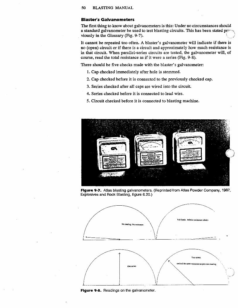
50 BLASTING MANUAL
Blaster's Galvanometers The first thing to know about galvanometers is this: Under no circumstances should a standard galvanometer be used to test blasting circuits. This has been stated prr · viously in the Glossary (Fig. 9-7).
It cannot be repeated too often. A blaster's galvanometer will indicate if there is no (open) circuit or if there is a circuit and approximately how much resistance is in that circuit. When parallel-series circuits are tested, the galvanometer will, of course, read the total resistance as if it were a series (Fig. 9-8).
There should be five checks made with the blaster's galvanometer:
1. Cap checked immediately after hole is stemmed.
2. Cap checked before it is connected to the previously checked cap.
3. Series checked after all caps are wired into the circuit.
4. Series checked before it is connected to lead wire.
5. Circuit checked before it is connected to blasting machine.
Figure 9-7. Atlas blasting galvanometers. (Reprinted from Atlas Powder Company, 1987, Explosives and Rock Blasting, figure 6.20.)
No rcadin~ No resistance
L= ... ======== ===----
One scrteS \/ /
Figure 9-8. Readings on the galvanometer.
Full Scale; Infinite resistance (shoo)
========- -
T\\O series.
each of the same resistance as prcnous read mg
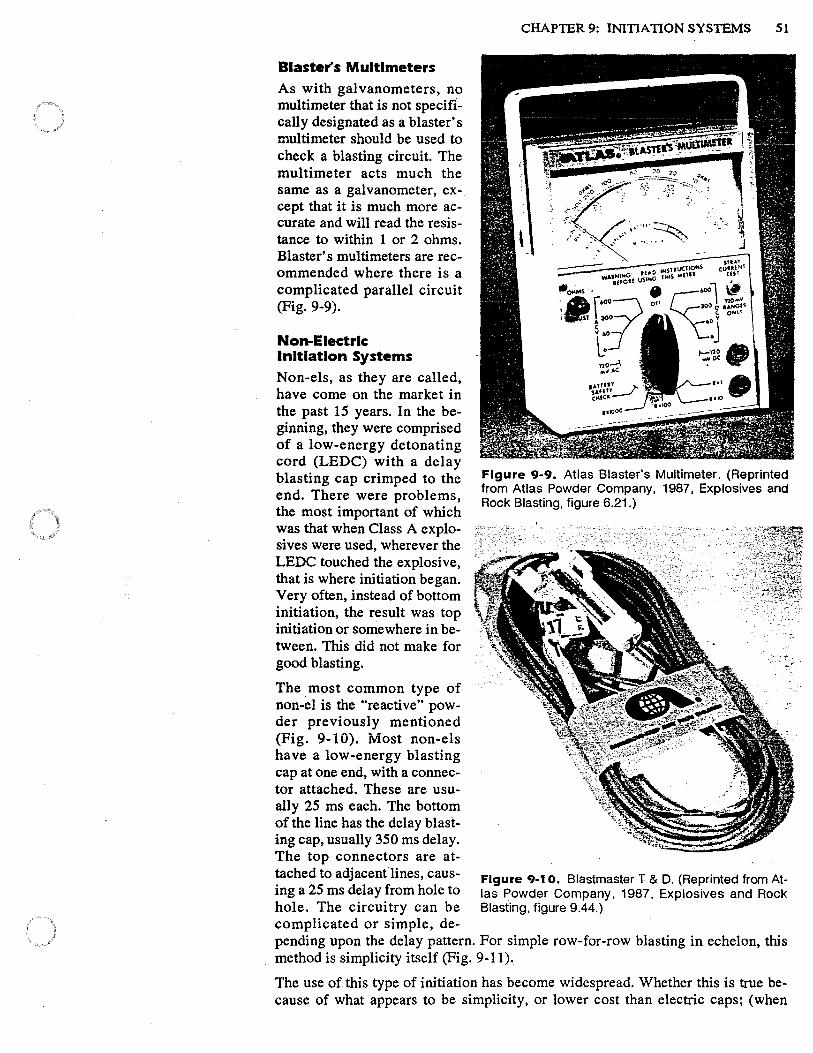
Blaster's Multlmeters As with galvanometers, no multimeter that is not specifically designated as a blaster's multimeter should be used to check a blasting circuit. The multimeter acts much the same as a galvanometer, ex-. cept that it is much more accurate and will read the resistance to within 1 or 2 ohms. Blaster's multimeters are recommended where there is a complicated parallel circuit (Fig. 9-9).
Non-Electrlc Initiation Systems Non-els, as they are called, have come on the market in the past 15 years. In the beginning, they were comprised of a low-energy detonating cord (LEDC) with a delay blasting cap crimped to the end. There were problems, the most important of which was that when Class A explosives were used, wherever the LEDC touched the explosive, that is where initiation began. Very often, instead of bottom initiation, the result was top initiation or somewhere in between. This did not make for good blasting.
The . most common type of non-el is the "reactive" powder previously mentioned (Fig. 9-10). Most non-els have a low-energy blasting cap at one end, with a connector attached. These are usually 25 ms each. The bottom of the line has the delay blasting cap, usually 350 ms delay. The top connectors are attached to adjacent lines, causing a 25 ms delay from hole to hole. The circuitry can be complicated or simple, de
CHAPTER 9: INITIATION SYSTEMS 51
Figure 9-9. Atlas Blaster's Multimeter. (Reprinted from Atlas Powder Company, 1987, Explosives and Rock Blasting, figure 6.21.)
Figure 9-1 o. Blastmaster T & D. (Reprinted from Atlas Powder Company, 1987. Explosives and Rock Blasting, figure 9.44.)
pending upon the delay pattern. For simple row-for-row blasting in echelon, this method is simplicity itself (Fig. 9-11 ).
The use of this type of initiation has become widespread. Whether this is true because of what appears to be simplicity, or lower cost than electric caps; (when
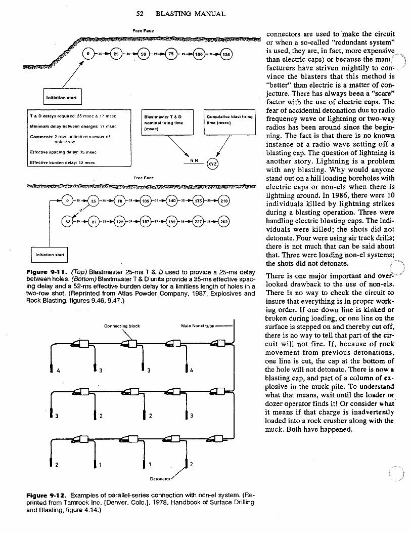
Initiation start
T & 0 delays required: 35 msec & 17 msec
Minimum delay between charges: 17 msec
Comments: 2 row. unlimited number of holes/row
Ellective spacing delay: 35 msec
Effective burden delay: 52 msec
52 BLASTING MANUAL
Free Face
Blast master T & 0
nominal firing lime
(msec)
Free Face
Cumulative blast firing
lime(msec),
NN Q ---,e;
.. ~ .. ---0-.. -9-.. ~ .. ~··---E) ,,
Gf..~ .. --@-··~ .. -9-.. ~ .. -9
Initiation start
Figure 9-11. (Top) Blastmaster 25-ms T & D used to provide a 25-ms delay between holes. (Bottom) Blastmaster T & D units provide a 35-ms effective spacing delay and a 52-ms effective burden delay for a limitless length of holes in a two-row shot. (Reprinted from Atlas Powder. Company. 1987, Explosives and Rock Blasting, figures 9.46, 9.47.)
Connecting block Main Nonel tube--
4 3 3
3 2 2 3
2 2
Detonator
Figure 9-12. Examples of parallel-series connection with non-el system. (Reprinted from Tamrock Inc. [Denver. Colo.], 1978, Handbook of Surface Drilling and Blasting, figure 4.14.)
connectors are used to make the circuit or when a so-called "redundant system" is used, they are, in fact, more expensive than electric caps) or because the manr · facturers have striven mightily to convince the blasters that this method is "better" than electric is a matter of conjecture. There has always been a "scare" factor with the use of electric caps. The fear of accidental detonation due to radio frequency wave or lightning or two-way radios has been around since the beginning. The fact is that there is no known instance of a radio wave setting off a blasting cap. The question of lightning is another story. Lightning is a problem with any blasting. Why would anyone stand out on a hill loading boreholes with electric caps or non-els when there is lightning around. In 1986, there were 10 individuals killed by lightning strikes during a blasting operation. Three were handling electric blasting caps. The individuals were killed; the shots did not detonate. Four were using air track drills; there is not much that can be said about that. Three were loading non-el systems; the shots did not detonate.
There is -one major important and over~ looked drawback to the use of non-els. There is no way to check the circuit to insure that everything is in proper working order. If one down line is kinked or broken during loading, or one line on the surface is stepped on and thereby cut off, there is no way to tell that part of the circuit will not fire. If, because of rock movement from previous detonations, one line is cut, the cap at the bottom of the hole will not detonate. There is now a blasting cap, and part of a column of explosive in the muck pile. To understand what that means, wait until the loader or dozer operator finds it! Or consider v.hat it means if that charge is inadvcncntly loaded into a rock crusher along with the muck. Both have happened.
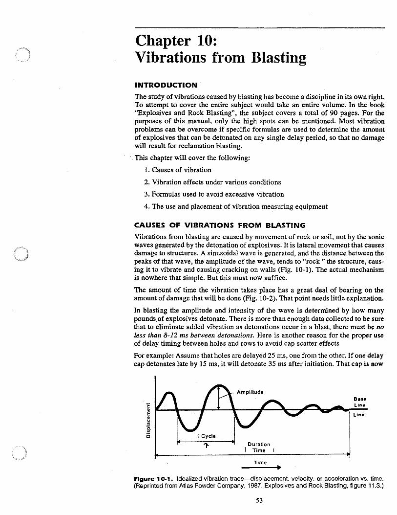
Chapter 10: Vibrations from· Blasting
INTRODUCTION .
The study of vibrations caused by blasting has become a discipline in its own right. To attempt to cover the entire subject would take an entire volume. In the book "Explosives and Rock Blasting", the subject covers a total of 90 pages. For the purposes of this manual, only the high spots can be mentioned. Most vibration problems can be overcome if specific formulas are used to determine the amount of explosives that can be detonated on any single delay period, so that no damage will result for reclamation blasting .
. This chapter will cover the following:
1. Causes of vibration
2. Vibration effects under various conditions
3. Formulas used to avoid excessive vibration
4. The use and placement of vibration measuring equipment
CAUSES OF VIBRATIONS FROM BLASTING
Vibrations from blasting are caused by movement of rock or soil, not by the sonic waves generated by the detonation of explosives. It is lateral movement that causes damage to structures. A sinusoidal wave is generated, and the distance between the peaks of that wave, the amplitude of the wave, tends to "rock " the structure, causing it to vibrate and causing cracking on walls (Fig. 10-1). The actual mechanism is nowhere that simple. But this must now suffice.
The amount of time the vibration takes place has a great deal of bearing on the amount of damage that will be done (Fig. 10-2). That point needs little explanation.
In blasting the amplitude and intensity of the wave is determined by how many pounds.of explosives detonate. There is more than enough data collected to be sure that to eliminate added vibration as detonations occur in a blast, there must be no less than 8-12 ms between detonations. Here is another reason for the proper use of delay timing between holes and rows to avoid cap scatter effects
For example: Assume that holes are delayed 25 ms, one from the other. If one delay cap detonates late by 15 ms, it will detonate 35 ms after initiation. That cap is now
1 Cycle
Duration I Time
Time
B••• Lint>
Figure 10-1. Idealized vibration trace-displacement, velocity, or acceleration vs. time. (Reprinted from Atlas Powder Company, 1987. Explosives and Rock Blasting, figure 11.3.)
53
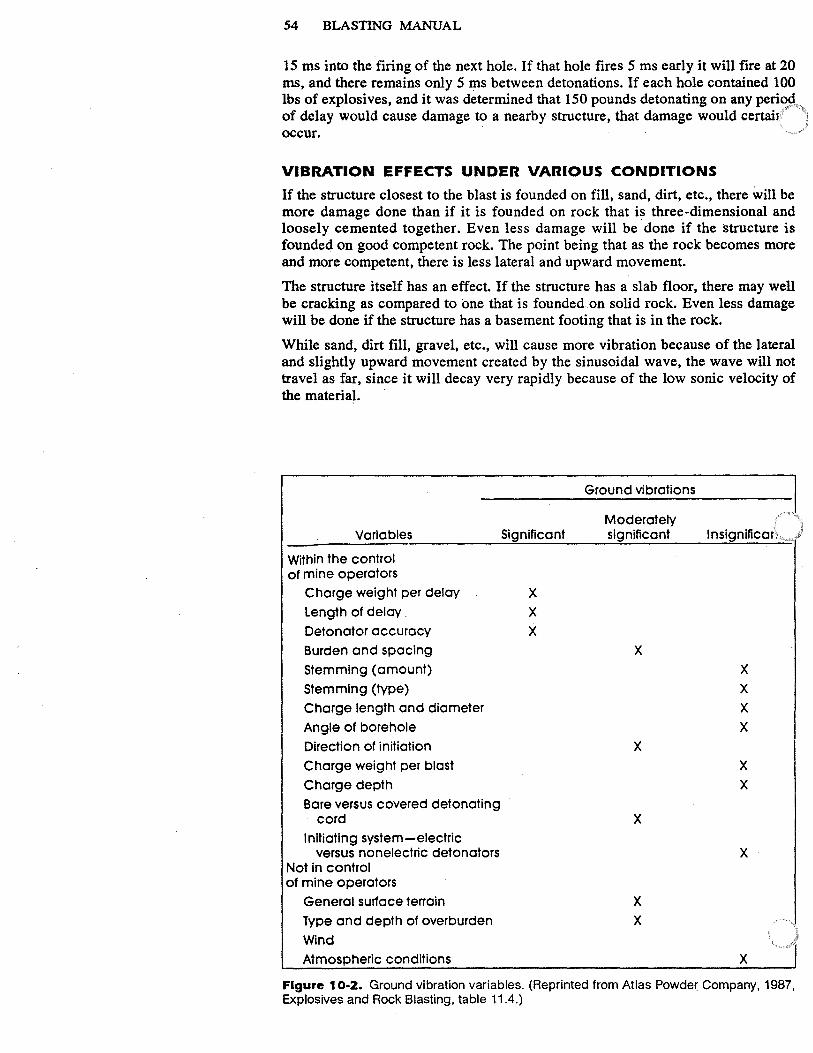
54 BLASTING MANUAL
15 ms into the firing of the next hole. If that hole fires 5 ms early it will fire at 20 ms, and there remains only 5 ms between detonations. If each hole contained 100 lbs of explosives, and it was determined that 150 pounds detonating on any peri~ of delay would cause damage to a nearby structure, that damage would certai1 occur.
VIBRATION EFFECTS UNDER VARIOUS CONDITIONS
If the structure closest to the blast is founded on fill, sand, dirt, etc., there will be more damage done than if it is founded on rock that is three-dimensional and loosely cemented together. Even less damage will be done if the structure is founded on good competent rock. The point being that as the rock becomes more and more competent, there is less lateral and upward movement.
The structure itself has an effect. If the structure has a slab floor, there may well be cracking as compared to one that is founded.on solid rock. Even less damage will be done if the structure has a basement footing that is in the rock.
While sand, dirt fill, gravel, etc., will cause more vibration because of the lateral and slightly upward movement created by the sinusoidal wave, the wave will not travel as far, since it will decay very rapidly because of the low sonic velocity of the material. ·
Ground vibrations
Moderately Variables Significant significant lnsignlficor .....
Within the control of mine operators
Charge weight per delay X Length of delay . X Detonator accuracy X Burden and spacing X Stemming (amount) X Stemming (type) X Charge length and diameter X Angle of borehole X Direction of initiation X Charge weight per blast X Charge depth X Bore versus covered detonating
cord X Initiating system-electric
versus nonelectric detonators X Not in control of mine operators
General surface terrain X Type and depth of overburden X Wind
l Atmospheric conditions X
Figure 10-2. Ground vibration variables. (Reprinted from Atlas Powder Company, 1987, Explosives and Rock Blasting, table 11.4.)
CHAPTER 10: VIBRATIONS FROM BLASTING S5
FORMULAS TO AVOID EXCESSIVE VIBRATIONS
There are two formulas that can be used to avoid possible vibration damage: the New Jersey-"energy ratio" formula and the scaled distance formula.
New Jersey "Energy Ratio" Formula This formula, which has been accepted in most courts, is used where the distance between structure and blast is very small. It states that you will not exceed a peak particle velocity (PPV) of 2 inches per second per second if you hold the explosive weight on any single delay period to .25 lbs per foot of distance to the structure.
For example, a distance of 12 feet.
12 feet x .25 = explosive weight 3 pounds per delay.
The formula is reliable up to about 100 feet.
Scaled Distance Formula
The second and more commonly used formula is known as the "scaled distance formula". It was devised by the U.S. Bureau of Mines for use particularly in open pit coal mines, butis now used by most agencies, mines, and quarries. The formula is:
D / (W).5 Where D = distance and W = weight of the charge on any single delay period.
The "scaled" portion of the formula can be anywhere from 50 to as low as 20, depending on the rock type and structure type.
For example: If the structure is 100 feet away and founded on overburden, the scaled distance should be 50. ·
100 / 50 = 2 2 is the square root of the charge, therefore the total explosive weight should not exceed 4 pounds.
Obviously this figure is very low. In this instance the New Jersey formula may be used. (100 x .25 = 25 lbs)
If, on the other hand, the structure is 1200 feet away and founded on rock, the scaled distance could be 30.
1200 /30 = 40 40 x 40 = 1600 lbs on any delay period.
Both formulas are rules of thumb rather than precise. Neither should be used except as a guide for the first blast. The only way to really determine whether or not damage has·been done is to use vibration measuring equipment.
THE USE AND PLACEMENT OF VIBRATION MEASURING EQUIPMENT
There are several types of measuring equipment specifically designed for measuring vibration created by blasting. All have special features. All work perfectly well,
· provided they are properly calibrated and properly placed. The main points to consider are:
Use
The equipment should be used only by persons thoroughly trained in the use of the particular machine. It is always preferable to have the machine placed and the results read by someone other than the blaster, contractor, mine operator, etc. In short, some who has no vested interest in the outcome.
Monitoring equipment that provides an immediate print-out is better, in most instances, than that which requires developing and interpretation. If the blasting is

56 BLASTING MANUAL
an on-going operation, there is a need to know, from blast to blast, what is going on, how close the results are to acceptable tolerances, etc. Any competent blaster should be able to use this type of equipment, since he has no control over the re:sults.
Placement
If an outside geotechnical firm is using the monitor, their operator will place the machine. If the work is being done in-house, the machine should be placed between the blast and the nearest structure. It is always a good idea to place more than one piece of monitoring equipment around the blast site.
PRE-BLAST SURVEYS
Too much emphasis cannot be placed upon making a pre-blast survey of all surrounding structures. The survey must be made by an outside specialist rather than by any member of the organization that is doing the blasting. All structures within any possible damage range must be thoroughly surveyed. All individuals who are involved in blasting should know that after the blast has taken place, owners of nearby structures will find cracks, settlement, displacement, all of which were preexisting, but never noticed. The lack of a proper survey by a qualified specialist is an open invitation to lawsuits. The damage may be real or imagined, but it will be a problem.
Chapter 11: Blasting Plans and Logs
INTRODUCTION
Blasting Plans
Blasting plans are a normal requirement for any blasting operation. The contractor who is responsible for the blasting is asked to submit to the contracting agency a general outline detailing how the blasting is to proceed. In the private sector, the contractor should require that the blaster, blasting foreman, or whomever else may be responsible for the work, submit a blasting plan as well. The plan, if required by an outside agency, should not be "accepted" by that agency. Note should be made that the plan, if not refused, does not mean that the agency necessarily approves the plan, but accepts it only in that there is no apparent danger to property, people, or the· environment. Under no circumstance should anyone in an oversight capacity tell the person who is directly responsible for the blasting exactly how to do the work. All specific details should be left to those who are directly responsible for the results of the blasting.
Blasting Logs Blasting logs are made on the site, as each hole is primed, loaded, stemmed, wired, and connected to the circuit, be it non-electric or electric. There should not be any what are known in the trade as, "barroom logs". That is, the log must not be made after the fact, but during the operation. Blasting logs should be kept for a period of time after the work is completed so that they can be referred to at a later date if it is required for one or more reasons.
REQUIRED INFORMATION
Blasting Plans
The following information should be required on all blasting plans:
Station at beginning of blast and end of blast (if applicable)
Average depth of holes to grade
Diameter of borehole
Average amount of sub-drill
Spacing of holes
Burden
Stemming
Type of explosive to be used
Manufacturer of explosive (technical data sheet to accompany plan)
VOD and De of explosive
Size of cartridges (if applicable)
Average pounds of explosives per hole
Total amount of explosives in blast
Type, VOD, De, size of primer (if applicable)
57
58 BLASTING MANUAL
Method of initiation (electric or non-electric)
If non-electric, type of initiator (reactive.powder, detaline, etc.)
Placement of initiator (bottom, center, top, double primed, etc.)
Number of delays
Number of pounds of explosive per delay period
-Number of rows of holes
Number of holes per row
If electric initiation, type, size, and capacity of blasting machine
Number of detonators in each series (if applicable)
Number of series in parallel (if applicable)
Estimated date and time of blast
Names of Blaster in Charge, and all helpers
Means of guarding the blast area during blasting
Type and number of audible warning signals
Cubic yards of rock estimated (including calculations)
Blasting Logs
Blasting logs must have the following information:
Depth of hole (measured after plug is removed and before any loading)
Amount of sub-drill
Delay period
Weight or size or name of primer (if applicable)
Pounds of explosives (in feet, if poured explosives are used)
Amount of water in hole (if applicable)
Amount of stemming (in feet)
To be filled out after all loading, wiring, and firing is completed:
Name _of blaster and helpers
Date and time of blast
Weather conditions
A detailed report on misfired holes, and cause thereof (if applicable)
Results of blast
Amount, if any, of fly rock
Any damage or injury reported
Total pounds of explosives used
Total number of each delay period used
Type of initiation ( electric or non-electric)
Total cubic yards of rock (including calculations)
Comments (to include any untoward occurrences)
Signature of Blaster in Charge

CHAPTER 11: BLASTING PLANS AND LOGS 59
A suggested blasting log and method of recording information is found on the following unnumbered page.


EXPLOSIVES SERVICES COR POR ATIO N
BLASTING LOG
PROJECT DATE ___ ~~~~-
LOG NUMBER~--~~~- BLASTER IN CHARGE~~~~~~~~~~~~--
HOLE HOLE WATER DELAY CHARGE CHARGE CHARGE STEM COMMENTS # DEPTH IN HOLE PERIOD
- - -·. - - ~ - - - -· -1 2 --
~-- I -4 5 6 7 8 -9 0
1 1 i--- - -·
12 __ tL .. - I
14 ! 15 16
_17 18 -·--· 19
I . 20 21 I 22 ~
24 25 26 ---27 ~
29 30 31 32
~-3 ~4
35 _3_Q
~.?. 28
39 -_A_O
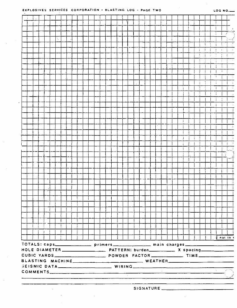
EXPLOSIVES SERVICES CORPORATION • BLASTING LOG • PAGE TWO LOG NO._
r I ' I .
I I ! I i I I I I I
i I I I I I
I I I I i ! I ' I : '
I I I I I I I i I ' I I I I -· I I
' ! ! I i I ! I ·-I i
I i i i I i i i I ! !
I
I I I I ' I I I I I I ! I
I I I I I i I I I ! !
l I i I I I !
I I I I ! I I I I ! I l I i i i
I I I
i i I I I I i i i ; I I
I I I
! ' ' I I I ! !
i I I I I I i i I ' ·-I I I i I i I I I I
I ! I i I ! ! ! I
I I ! I ' i I i i I I
I i I I I I ! I I I
i I I I I i I I I I I
I I I I I I ! I i I I ! ! ! L I ! i ! I l i i ! '
I i I I i I i I ! ! !
i i I I ! I ! I i I i I
~ I
j7' ) 1-- - ~ - .. -- ·--,__ - - ....
I I I ·- ...... I. I -l j I I I I ...
I I I I ! i I ! I I I l I I
I I I I ... - I
!
I I i i I I I I I i
: I I r i l I I I I ' I I I I I ,
I I I I I I I I I I
I I '
, l I I I I I i I ! I I I
I I ! I not to!
TOTALS: caps.._ ______ primers---.....---- main charges ________ _ HOLE DIAMETER ________ PATTERN: burden X spacing _____ _
CUBIC YARDS _________ POWDER FACTOR TIME _____ _
BLASTING MACHINE------------- WEATHER ___________ _ .i EIS MIC DAT A __________ WI RI NG _________________ _ COMMENTS ______________________________ _
SIG NATURE-------------

APPENDIX "A"
Addendum One
Drills and Drilling
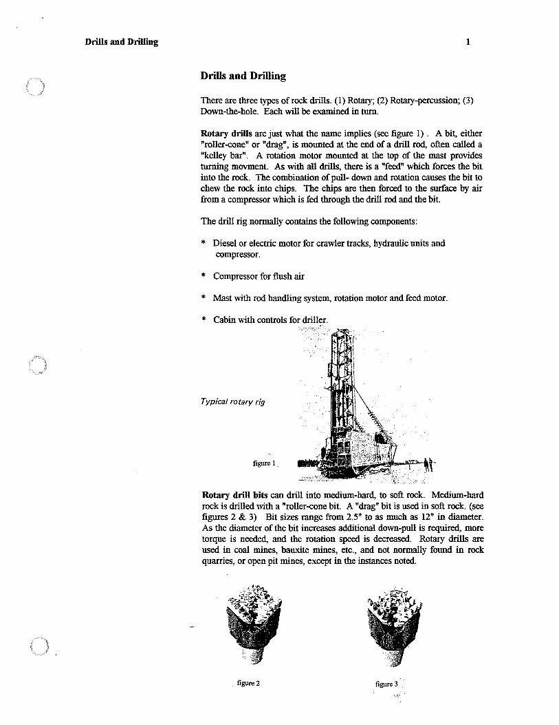
Drills and Drilling 1
Drills and Drilling
There are three types of rock drills. (1) Rotary; (2) Rotary-percussion; (3) Down-the-hole. Each will be examined in turn.
Rotary drills are just what the name implies (see figure 1) . A bit, either "roller-cone" or "drag", is mounted at the end of a drill rod, often called a "kelley bar". A rotation motor mounted at the top of the mast provides turning movment. As with all drills, there is a "feed" which forces the bit into the rock. The combination of pull- down and rotation causes the bit to chew the rock into chips. The chips are then forced to the surface by air from a compressor which is fed through the drill rod and the bit.
The drill rig normally contains the following components:
* Diesel or electric motor for crawler tracks, hydraulic units and compressor.
* Compressor for flush air
* Mast with rod handling system, rotation motor and feed motor.
* Cabin with controls for driller.
Typical rotary rig
figure 1.
Rotary drill bits can drill into medium-hard, to soft rock. Medium-hard rock is drilled with a "roller-cone bit. A "drag" bit is used in soft rock. (see figures 2 & 3) Bit sizes range from 2.5" to as much as 12" in diameter. As the diameter of the bit increases additional down-pull is required, more torque is needed, and the rotation speed is decreased. Rotary drills are used in coal mines, bauxite mines, etc., and not normally found in rock quarries, or open pit mines, except in the instances noted.
figure 2 figure 3 ·
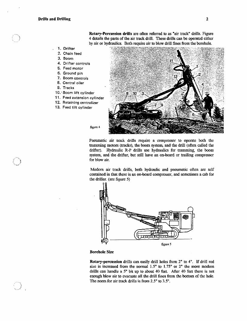
Drills and Drilling
·1. Drifter 2. Chain feed 3. Boom
2
Rotary-Percussion drills are often referred to as "air track" drills. Figure 4 details the parts of the air track drill. These drills can be operated either by air or hydraulics. Both require air to blow drill fines from the borehole.
4. Drifter controls 5. Feed motor 6. Ground pin 7. Boom controls 8. Central oiler 9. Tracks
10. - Boom lift cylinder 11. Feed extension cylinder 12. Retaining centralizer 13. Feed tilt cylinder
figure 4
Pneumatic air track drills require a compressor to operate both the tramming motors (tracks), the boom system, and the drill (often called the drifter). Hydraulic R-P drills use hydraulics for tramming, the boom system, and the drifter, but still have an on..t>oard or trailing compressor for blow air.
Modem air track drills, both hydraulic and pneumatic often are self contained in that there is an on..t>oard compressor, and sometimes a cab for the driller. (see figure 5)
Borehole Size
Rotary-percussion drills can easily drill holes from 2" to 4". If drill rod size is increased from the normal 1.5" to 1.75" or 2" the more modern drills can handle a 5" bit up to about 40 feet. After 40 feet there is not enough blow air to evacuate all the drill fines from the bottom of the hole. The norm for air track drills is from 2.5" to 3.5".
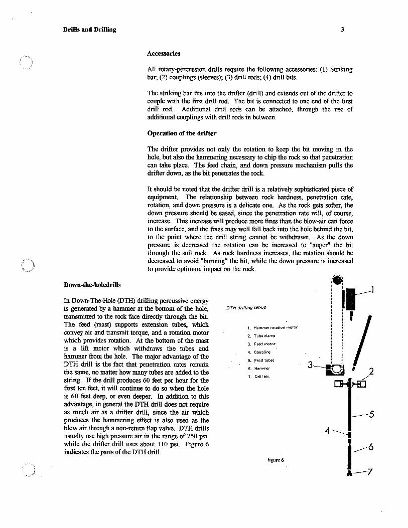
Drills and Drilling
Down-the-holedrills
3
Accessories
All rotary-percussion drills require the following accessories: (1) Striking bar; (2) couplings (sleeves); (3) drill rods; (4) drill bits.
The striking bar fits into the drifter ( drill) and extends out of the drifter to couple with the first drill rod. The bit is connected to one end of the first drill rod. Additional drill rods can be attached, through the use of additional couplings with drill rods in between.
Operation of the drifter
The drifter provides not only the rotation to keep the bit moving in the hole, but also the hammering necessary to chip the rock so that penetration can take place. The feed chain, and down pressure mechanism pulls the drifter down, as the bit penetrates the rock.
It should be noted that the drifter drill is a relatively sophisticated piece of equipment. The relationship between rock hardness, penetration rate, rotation, and down pressure is a delicate one. As the rock gets softer, the down pressure should be eased, since the penetration rate will, of course, increase. This increase will produce more fines than the blow-air can force to the surface, and the fines may well fall back into the hole behind the bit, to the point where the drill string cannot be withdrawn. As the down pressure is decreased the rotation can be increased to "auger" the bit through the soft rock. As rock hardness increases, the rotation should be decreased to avoid "burning" the bit, while the down pressure is increased to provide optimum impact on the rock. .• ,-... ,
I I
In Down-The-Hole (DTH) drilling percussive energy is generated by a hammer at the bottom of the hole, transmitted to the rock face directly through the bit. The feed (mast) supports extension tubes, which convey air and transmit torque, and a rotation motor which provides rotation. At the bottom of the mast is a lift motor which withdraws the tubes and hammer from the hole. The major advantage of the DTII drill is the fact that penetration rates remain the same, no matter how many tubes are added to the string. If the drill produces 60 feet per hour for the first ten feet, it will continue to do so when the hole is 60 feet deep, or even deeper. In addition to this advantage, in general the DTH drill does not require as much air as a drifter drill, since the air which produces the hammering effect is also used as the blow air through a non-return flap valve. DTH drills usually use high pressure air in the range of 250 psi. while the drifter drill uses about 110 psi. Figure 6 indicates the parts of the DTH drill.
0TH drilling set-up
1. Hammer rotation motor
2. Tube clamp
3. Feed motor
4. Coupling
5. Feed tubes
6. Hammer
7. Drill bit.
i ,a----1 I I I : : I I I
' I ' I I I I I I
' ' 3----ig • 2
~Kd
--5
figure 6
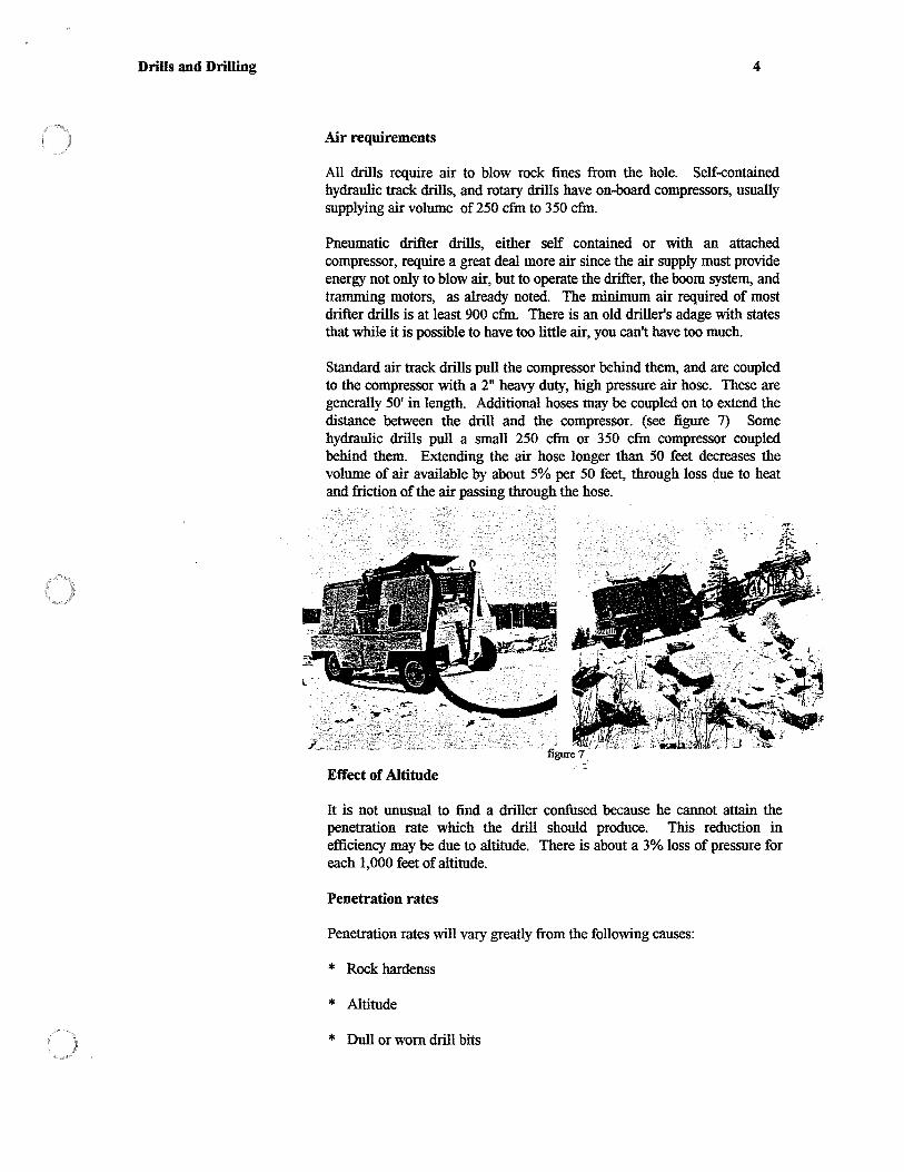
Drills and Drilling 4
Air requirements
All drills require air to blow rock fines from the hole. Self-contained hydraulic track drills, and rotary drills have on-board compressors, usually supplying air volume of 250 cfm to 350 cfm.
Pneumatic drifter drills, either self contained or with an attached compressor, require a great deal more air since the air supply must provide energy not only to blow air, but to operate the drifter, the boom system, and tramming motors, as already noted. The minimum air required of most drifter drills is at least 900 cfm. There is an old driller's adage with states that while it is possible to have too little air, you can't have too much.
Standard air track drills pull the compressor behind them, and are coupled to the compressor with a 2" heavy duty, high pressure air hose. These are generally 50' in length. Additional hoses may be coupled on to extend the distance between the drill and the compressor. (see figure 7) Some hydraulic drills pull a small 250 cfm or 350 cfm compressor coupled behind them. Extending the air hose longer than 50 feet decreases the volume of air available by about 5% per 50 feet, through loss due to heat and friction of the air passing through the hose.
Effect of Altitude
It is not unusual to find a driller confused because he cannot attain the penetration rate which the drill should produce. This reduction in efficiency may be due to altitude. There is about a 3% loss of pressure for each 1,000 feet of altitude.
Penetration rates
Penetration rates will vary greatly from the following causes:
* Rock hardenss
* Altitude
* Dull or worn drill bits
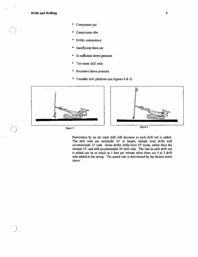
Drills and Drilling
* Compressor psi
* Compressor cfm
* Driller competency
* Insufficient blow-air
* In sufficient down pressure
* Too many drill rods
* Excessive down pressure
* Unstable drill platform (see figures 8 & 9)
figure 8 .
5
Penetration by an air track drill will decrease as each drill rod is added. The drill rods are mormally IO' in length, though most drills will accommodate 12' rods. Some drifter drills have 25' masts, rather than the normal 15', and will accommodate 20' drill rods. The loss as each drill rod is added can be as much as 1 foot per minute when there are 4 to 5 drill rods added to the string. The actual rate is determined by the factors noted above.
Addendum Two
Blasting Operations Check List for Supervisory Personnel
Check List 1
Pre-Blast Check List for Supenisory Personnel
This check list is a guidefor supervisory or over-sight personnel whose function it is to insure that safety procedures are set and complied with. Supervisory or over-sight personnel should NOT make specific recommendations of a technical nature, nor interfere with the performance of the Blaster-in-charge unless there is a clear and obvious violation of safety procedures and/or regulations. In short, do not tell those responsible for the work HOW to do the work, only what is to be accomplished, and what he Can Not do. Under no circumstances should the work be allowed to continue if what is being done is dangerous to persons, property or the environment.
Blaster-in-charge qualifications
(a) Has the BIC submitted a full and accurate resume. Has the resume been checked for accuracy. Is the BIC qualified by both training and experience to do the work required?
(b) Are the licenses of the BIC current, and endorsed for the type of blasting required?
(c) Are all helpers qualified and experienced?
(d) Will the BIC be present during all loading, wiring, and detonating activities?
(e) Has the BIC submitted the blasting plan? Is the plan accurate, readable, and signed by the BIC?
Blasting Plan
(a) Has a blasting plan been submitted? (The plan should be submitted no less than 72 hours before drilling commences)
(b) Is the spacing of holes at or less than 1/2 the depth of the hole?
(c) Is the stemming equal to or greater than .7 of the planned burden? Is the calculated powder factor correct?
( d) Is the blast sufficiently delayed to avoid damage due to vibration? Has the BIC included the maximum pounds of explosive for any single delay period?
(e) Does the blast plan indicate vibration criteria in accordance with the Scaled Distance Formula or other mathematical formulations? (First blast only if blast monitoring equipment is to be used.) If monitoring equipment is not used, each plan should have information regarding distance to nearest structure, pounds of explosive on any single delay period, and sufficient delay from period to period to avoid cap scatter.

Check List
Blasthole Loading Check List
(a) Is there a loading plan?
2
(b) Is the BIC really in charge? (If there is confusion, uncertainty, and a lack of planning and control the operation should be halted immediately, and until some organization is apparent!)
(c) Are explosives off-loaded from vehicles, and neatly stacked away from actual loading?
( d) Are powder poles sufficiently long to reach the bottom of the deepest borehole?
(e) Is the depth of the hole checked before loading?
(f) Is the proper information as required on the shot log recorded as each hole is loaded?
{g) Are individual loading holes qualified, and are they supervised?
{h) Are there too many individuals involved in loading? Have all spectators been removed from the area?
(i) If electric caps are used are they checked with a blaster's galvanometer after stemming is loaded?
(J) If electric caps are used is more than one person wiring any one series?
(k) If electric caps are used is each series checked for proper resistance with a blaster's galvanometer before connection into a parallel-series circuit?
(I) If surface delays are used is the entire area cleared before surface delays are connected into the system?
(m) Is the loading area clear of trash, equipment, etc.?
(n) Are no smoking signs posted? Has a smoking area been designated?
{ o) Are vehicles parked at least 50 feet from loading operations?
(p) Is everyone clear of the area before final connections are made?
2

Check List 3
Pre-blast Inspection
(a) Is the blast area clear of all vehicles, equipment, explosives, trash, and personnel?
(b) Is there a blast site control plan?
(c) Have site guards been properly briefed by the BIC?
( d) Is there a warning signal to be used by gurads in the event the blast must be aborted?
(e) Has the BIC insured that there are no persons exposed to potential fly rock?
(t) Has the BIC insured that the audible signals can be heard by the guard farthest from the blast site?
(g) If (f) above is impossible, has the BIC established radio control for the guard or guards?
(h) Are "Blast Area" signs in place at all approaches to the blast site?
(i) Has the BIC insured that all personnel on the project are familiar with the pre-blast, and post-blast audible signals?
G) Are all personnel wearing hard hats?
(k) Is everyone involved, including spectators, under cover before the blast?
Safety Check for Drills and Drilling
(a) Are all drillers, helpers, and persons near drilling operations properly equipped?
1. Gloves on hands at all time when using drill
2. Hard hats on at all times
3. Safety glasses available and worn
4. Dust equipment inplace and in use, including dust masks for driller and helper
(b) Are all main air feed hoses properly safety chained?
(c) Are compressor wheels blocked at all times when compressor is not moving?
( d) Is the mast laid back to nearly horizontal when drill is tramming (Boom extension in)?
3

Check List 4
(e) If drilling is on a steep slope is the tugger winch properly secured?
(f) Is winch cable sufficient to completely hold the drill? Is it in good condition? Is the winch brake operative and being used?
(g) If drilling is on a steep slope is the driller tied off to something other than the drill?
(h) If the driller to be left alone is there someone who can keep visual contact with him at all times?
(i) Are the tracks of the platform firmly seated on the ground?
Post-Blast Check List
(a) Did the BIC check the entire blast area before allowing anyone else into the blasted area?
(b) Did the BIC insure that all smoke from the blast had dissipated before entering the blast area?
(c) Did the BIC insure that all guards checked in after the blast, and remained on station until the all clear had sounded?
(d) Was the entire area checked for misfires?
(e) If the blast was initiated electrically were all wires which were visible checked for continuity before anyone was allowed into the area?
(f) If the blast was initiated with "non-els" was the area checked for cut-offs or unfired surface connectors?
(g) If any misfires occured did the BIC take proper action to clear the misfire before allowing anyone to return to the area?
(h) Was the blast site checked for possible live charges?
(i) Were all explosives returned to magazines?
4

Addendum Three
Estimating Worksheet

Step 1:
Make evaluation of rock formation
Step 2:
Estimating The Blasting Project
Work Sheet
RQ PQ DQ CQ
3D 2D LPS SPB SRB
Select explosives based on matching VOD to Vso
Step 3:
Determine "Z" of Rock
Step 4:
Determine K of explosive
Step 5:
Determine CPF (Powder Factor)
Step 6:
Z = 1.31 x Sg x (Vso/1000)
.418 x Dex (YOD/1000) (1 + .8De)
i K
Determine hole size. (Use largest diameter bit consistent with type of drill)
Step 7:
Determine Spacing (Be sure that spacing is not greater than l/2 depth of shallowest holes)
S = 3(C2 x De/ CPF)·5
Estimating work sheet 1
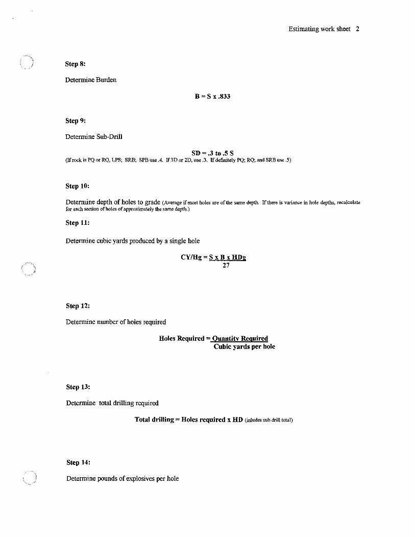
Estimating work sheet 2
Step 8:
Determine Burden
B =S x.833
Step 9:
Determine Sub-Drill
SD=.3 to.5 S (If rock is PQ or RQ, LPS; SRB; SPB use .4. If3D or 2D, use .3. If definitely PQ; RQ; and SRB use .5)
Step 10:
Determine depth of holes to grade (Average if most holes are ofthe same depth. Ifthere is variance in hole depths, recalculate for each section of holes of approximately the same depth.)
Step 11:
Determine cubic yards produced by a single hole
Sfep 12:
CY/Hg= S xB xHDg 27
Determine number of holes required
Step 13:
Holes Required = Quantity Required Cubic yards per hole
Determine total drilling required
Total drilling= Holes required x HD (inludes sub drill total)
Step 14:
Determine pounds of explosives per hole

Step 15:
Pounds per hole= Dex cl. x (HD -Ts) 3
Determine total explosives required
Step 13 x number of holes (Can also divide required yards by CPF)
Step 16:
Determine Cost of drilling
Estimating work sheet 3
1. Determine drill rate (Air track approx l foot per minute. Rotary drill approx 3 feet per minute. Hydraulic drill 1.5 feet per minute. Add 15 % for each drill rod added up to 30 feet. Add 20% for each drill rod over 30 feet, except for rotary or DTH. DTH drill rate stays the same.)
2. Determine number of hours of operation of drill.
Total feet of drilling required / drill rate
3. Determine cost of drill and compressor rental or amortization per hour (Cost per month 1 176 hours)
4. Add cost of Striker bars; drill bits; drill rods; couplings, rock drill oil (.5 gals hr.); compressor fuel (Divide cfm by 100). (Drill rods 4000-5000 feet; Bits 1000-1200 feet; Couplings 1500-2500 feet; Striker bar 2500 feet. Cost will vary greatly depending upon rock type, silica content of rock, competence of driller, terrain, etc.)
Step 17:
Determine cost of explosives
Step 14 x cost per pound
Step 18:
Determine cost of primers, if applicable
Number of holes x number of primers per hole x cost per primer
Step 19:
Determine cost of initiators
Step 20:
Determine cost of labor
Number of hours of drilling required x hourly wage of labor (2 men, driller and helper if applicable)

Step 21:
Determine cost ofloading, wiring, shot-firing
6 minutes per hole for loading and wiring (include cost per hour for Blaster and all helpers involved in wiring, removing explosives ,etc.)
Step 22:
Determine cost of moving drill for hole to hole
Estimating work sheet 4
Cost per hour for labor and drill and compressor x 4 minutes per hole for set up from hole to hole
Step 23:
Add cost of move in and move out of drill and compressor, set up time etc.
Step 24:
Add cost of overhead, taxes, contributions, and profit (depending on greed factor)
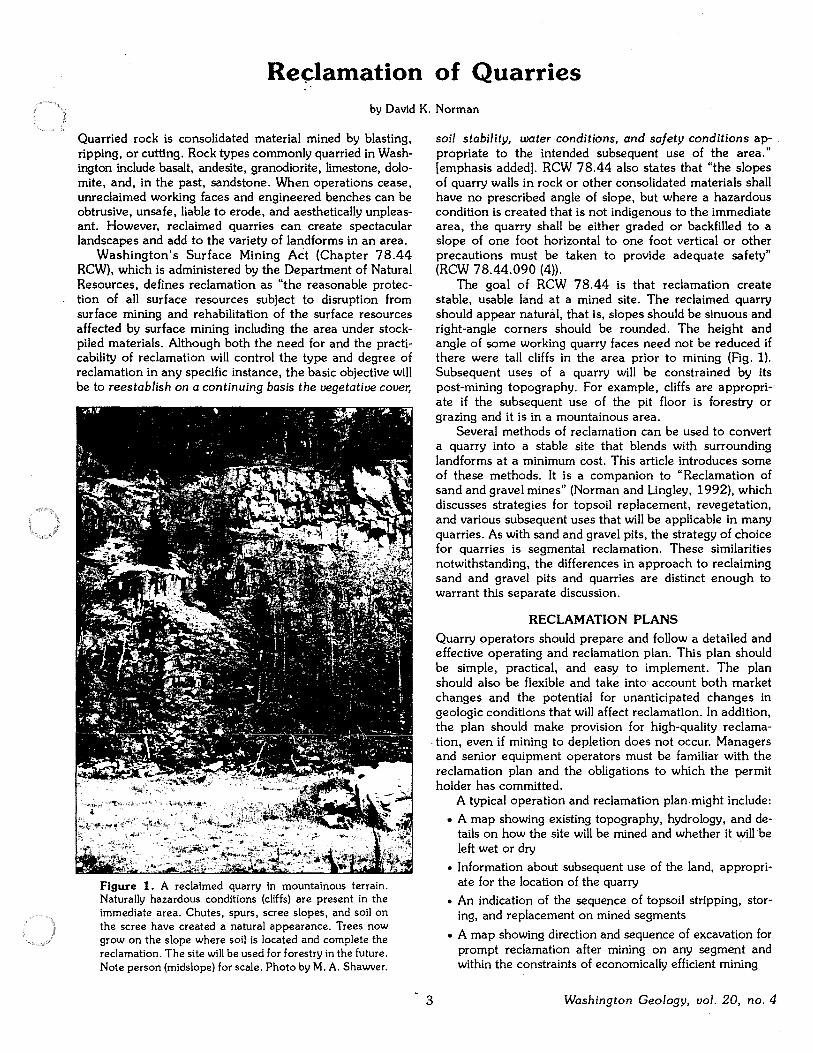
Reclamation of Quarries by David K. Norman
Quarried rock is consolidated material mined by blasting, ripping, or cutting. Rock types commonly quarried in Washington include basalt, andesite, granodiorite, limestone, dolomite, and, in the past, sandstone. When operations cease, unreclaimed working .faces and engineered benches can be obtrusive, unsafe, liable to erode, and aesthetically unpleasant. However, reclaimed quarries can create spectacular landscapes and add to the variety of landforms in an area.
Washington's Surface Mining Act (Chapter 78.44 RCW), which is administered by the Department of Natural Resources, defines reclamation as "the reasonable protection of all surface resources subject to disruption from surface mining and rehabilitation of the surface resources affected by surface mining including the area under stockpiled materials. Although both the need for and the practicability of reclamation will control the type and degree of reclamation in any specific instance, the basic objective will be to reestablish on a continuing basis the vegetative cover,
Figure 1. A reclaimed quarry in mountainous terrain. Naturally hazardous conditions (cliffs) are present in the immediate area. Chutes, spurs, scree slopes, and soil on the scree have created a natural appearance. Trees now grow on the slope where soil is located and complete the reclamation. The site will be used for forestry in the future. Note person (midslope) for scale. Photo by M.A. Shawver.
soil stability, water conditions, and safety conditions appropriate to the intended subsequent use of the area." [emphasis added). RCW 78.44 also states that "the slopes of quarry walls in rock or other consolidated materials shall have no prescribed angle of slope, but where a hazardous condition is created that is not indigenous to the immediate area, the quarry shall be either graded or backfilled to a slope of one foot horizontal to one foot vertical or other precautions must be taken to provide adequate safety" (RCW 78.44.090 (4)).
The goal of RCW 78.44 is that reclamation create stable, usable land at a mined site. The reclaimed quarry should appear natural, that is, slopes should be sinuous and right-angle corners should be rounded. The height and angle of some working quarry faces need not be reduced if there were tall cliffs in the area prior to mining (Fig. 1). Subsequent uses of a quarry will be constrained by its post-mining topography. For example, cliffs are appropriate if the subsequent use of the pit floor is forestry or grazing and it is in a mountainous area.
Several methods of reclamation can be used to convert a quarry into a stable site that blends with surrounding landforms at a minimum cost. This article introduces some of these methods. It is a companion to "Reclamation of sand and gravel mines" (Norman and Lingley, 1992), which discusses strategies for topsoil replacement, revegetation, and various subsequent uses that will be applicable in many quarries. As with sand and gravel pits, the strategy of choice for quarries is segmental reclamation. These similarities notwithstanding, the differences in approach to reclaiming sand and gravel pits and quarries are distinct enough to warrant this separate discussion.
RECLAMATION PLANS
Quarry operators should prepare and follow a detailed and effective operating and reclamation plan. This plan should be simple, practical, and easy to implement. The plan should also be flexible and take into account both market changes and the potential for unanticipated changes in geologic conditions that will affect reclamation. In addition, the plan should make provision for high-quality reclama-
. tion, even if mining to depletion does not occur. Managers and senior equipment operators must be familiar with the reclamation plan and the obligations to which the permit holder has committed.
3
A typical operation and reclamation plan might include:
• A map showing existing topography, hydrology, and details on how the site will be mined and whether it will be left wet or dry
• Information about subsequent use of the land, appropriate for the location of the quarry
• An indication of the sequence of topsoil stripping, storing, and replacement on mined segments
• A map showing direction and sequence of excavation for prompt reclamation after mining on any segment and within the constraints of economically efficient mining
Washington Geology, vol. 20, no. 4
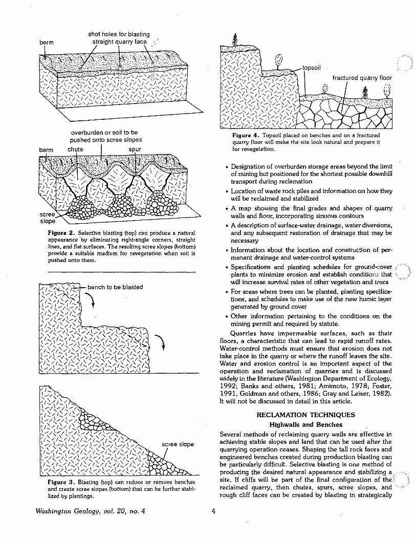
berm shot holes for blasting
straight quarry face
Figure 2. Selective blasting (top) can produce a natural appearance by eliminating right-angle comers, straight
.lines, and flat surfaces. The resulting scree slopes (bottom) provide a suitable medium for revegetation when soil is pushed onto them.
Figure 3. Blasting (top) can reduce or remove benches and create scree slopes (bottom) that can be further stabilized by plantings.
Washington Geology, vol. 20, no. 4 4
Figure 4. Topsoil placed on benches and on a fractured quarry floor will make the site look natural and prepare it for revegetation.
• Designation of overburden storage areas beyond the limit of mining but positioned for the shortest possible downhill transport during reclamation
• Location of waste rock piles and information on how they will be reclaimed and stabilized
• A map showing the final grades and shapes of quarry walls and floor, incorporating sinuous contours
• A description of surface-water drainage, water diversions, and any subsequent restoration of drainage that may be necessary
• Information about the location and construction of permanent drainage and water-control systems
• Specifications and planting schedules for ground-cover plants to minimize erosion and establish conditions, that will increase survival rates of other vegetation and trees
• For areas where trees can be planted, planting specifications, and schedules to make use of the new humic layer generated by ground cover
• Other information pertaining to the conditions on the mining permit and required by statute.
Quarries have impermeable surfaces, such as their floors, a characteristic that can lead to rapid runoff rates. Water-control methods must ensure that erosion does not take place in the quarry or where the runoff leaves the site. Water and erosion control is an important aspect of the operation and reclamation of quarries and is discussed widely in the literature (Washington Department of Ecology, 1992; Banks and others, 1981; Amimoto, 1978; Foster, 1991, Goldman and others, 1986; Gray and Leiser, 1982). It will not be discussed in detail in this article.
RECLAMATION TECHNIQUES Highwalls and Benches
Several methods of reclaiming quarry walls are effective in achieving stable slopes and land that can be used after the quarrying operation ceases. Shaping the tall rock faces and engineered benches created during production blasting can be particularly difficult. Selective blasting Is one method of producing the desired natural appearance and stabilizing a site. If cliffs will be part of the final configuration of the reclaimed quarry, then chutes, spurs, scree slopes, and rough cliff faces can be created by blasting in strategically
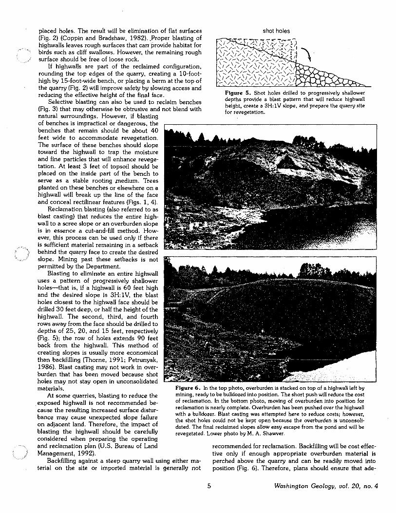
placed holes. The result will be elimination of flat surfaces (Fig. 2) (Coppin and Bradshaw, 1982) .. Proper blasting of highwalls leaves rough surfaces that can provide habitat for birds such as cliff swallows. However, the remaining rough surface should be free of loose rock.
If highwalls are part of the reclaimed configuration, rounding the top edges of the quarry, creating a 10-foothigh by 15-foot-wide bench, or placing a berm at the top of the quarry (Fig. 2) will improve safety by slowing access and reducing the effective height of the final face.
Selective blasting can also be used to reclaim benches (Fig. 3) that may otherwise be obtrusive and not blend with natural surroundings. However, if blasting of benches is impractical or dangerous, the benches that remain should be about 40 feet wide to accommodate revegetation. The surface of these benches should slope toward the highwall to trap the moisture and fine particles that will enhance revegetation. At least 3 feet of topsoil should be placed on the inside part of the bench to serve as a stable rooting .medium. Trees planted on these benches or elsewhere on a highwall will break up the line of the face and conceal rectilinear features (Figs. 1, 4).
Reclamation blasting (also referred to as blast casting) that reduces the entire highwall to a scree slope or an overburden slope is in essence a cut-and-fill method. However, this process can be used only if there is sufficient material remaining in a setback behind the quarry face to create the desired slope. Mining past these setbacks is not permitted by the Department.
shot holes
Figure 5. Shot holes drilled to progressively shallower depths provide a blast pattern that will reduce highwall height, create a 3H: 1 V slope, and prepare the quarry site for r:evegetation.
Blasting to eliminate an entire highwall uses a pattern of progressively shallower holes-that is, if a highwall is 60 feet high and the desired slope is 3H: 1 V, the blast holes closest to the highwall face should be drilled 30 feet deep, or half the height of the highwall. The second, third, and fourth rows away from the face should be drilled to depths of 25, 20, and 15 feet, respectively (Fig. 5); the row of holes extends 90 feet back from the highwall. This method of creating slopes is usually more economical than backfilling (Thorne, 1991; Petrunyak, 1986). Blast casting may not work in overburden that has been moved because shot holes may not stay open in unconsolidated materials.
At some quarries, blasting to reduce the . exposed highwall is not recommended because the resulting increased surface disturbance may cause unexpected slope failure on adjacent land. Therefore, the impact of blasting the highwall should be carefully considered when preparing the operating and reclamation plan (U.S. Bureau of Land
Figure 6. In the top photo, overburden is stacked on top of a highwall left by mining, ready to be bulldozed into position. The short push will reduce the cost of reclamation. In the bottom photo, moving of overburden into position for reclamation is nearly complete. Overburden has been pushed over the highwall with a bulldozer. Blast casting was attempted here to reduce costs; however, the shot holes could not be kept open because the overburden is unconsolidated. The final reclaimed slopes allow easy escape from the pond and will be revegetated. Lower photo by M.A. Shawver.
Management, 1992). Backfilling against a steep quarry wall using either ma
terial on the site or imported material is generally not
5
recommended for reclamation. Backfilling will be cost effective only if enough appropriate overburden material is perched above the quarry and can be readily moved into position (Fig. 6). Therefore, plans should ensure that ade-
Washington Geology, vol. 20, no. 4
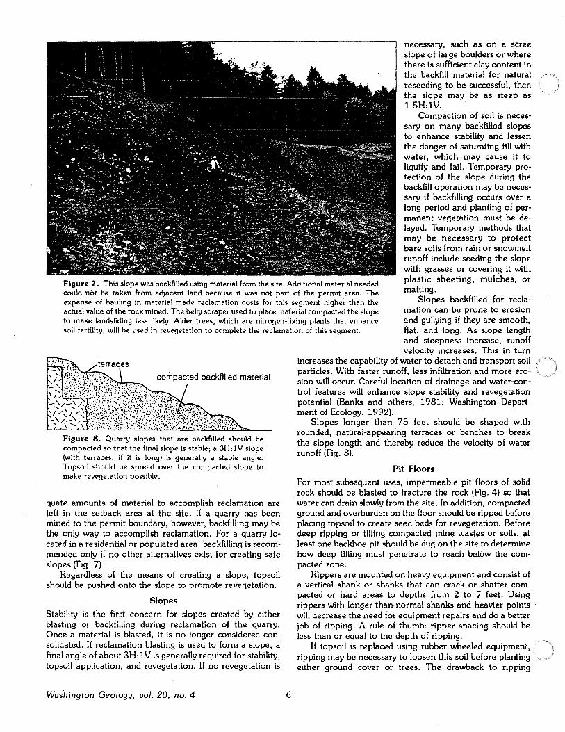
necessary, such as on a scree slope of large boulders or where there is sufficient clay content in the backfill material for natural reseeding to be successful, then the slope may be as steep as l.SH:lV.
Figure 7. This slope was backfilled using material from the site. Additional material needed could not be taken from adjacent land because it was not part of the permit area. The expense of hauling in material made reclamation costs for this segment higher than the actual value of the rock mined. The belly scraper used to place material compacted the slope to make landsliding less likely. Alder trees, which are nitrogen-fixing plants that enhance soil fertility, will be used in revegetation to complete the reclamation of this segment.
Compaction of soil is necessary on many backfilled slopes to enhance stability and Jessen the danger of saturating fill with water, which may cause it to liquify and fail. Temporary protection of the slope during the backfill operation may be necessary if backfilling occurs over a long period and planting of permanent vegetation must be delayed. Temporary methods that may be necessary to protect bare soils from rain or snowmelt rurioff include seeding the slope with grasses or covering it with plastic sheeting, mulches, or matting.
Slopes backfilled for reclamation can be prone to erosion and gullying if they are smooth, flat, and long. As slope length and steepness increase, runoff
··~-·~·-':.\.·, ..•
't ~ :?i.:\frt,::1i)':,,. compacted backfilled material
~~f f J:~~f:~~f t1~?f ~:~~;r;1[~\~1\:;i;;t ,, Figure 8. Quarry slopes that are backfilled should be compacted so that the final slope is stable; a 3H: 1 V slope (with terraces, if it is long) is generally a stable angle. Topsoil should be spread over the compacted slope to make revegetation possible.
quate amounts of material to accomplish reclamation are left in the setback area at the site. If a quarry has been mined to the permit boundary, however, backfilling may be the only way to accomplish reclamation. For a quarry located in a residential or populated area, backfilling is recommended only if no other alternatives exist for creating safe slopes (Fig. 7).
Regardless of the means of creating a slope, topsoil should be pushed onto the slope to promote revegetation.
Slopes Stability is the first concern for slopes created by either blasting or backfilling during reclamation of the quarry. Once a material is blasted, it is no longer considered consolidated. If reclamation blasting is used to form a slope, a final angle of about 3H: 1 Vis generally required for stability, topsoil application, and revegetation. If no revegetation is
Washington Geology, vol. 20, no. 4 6
velocity increases. This in turn increases the capability of water to detach and transport soil particles. With faster runoff, less infiltration and more erosion will occur. Careful location of drainage and water-control features will enhance slope stability and revegetation potential (Banks and others, 1981; Washington Depart-ment of Ecology, 1992). ·
Slopes longer than 75 feet should be shaped with rounded, natural-appearing terraces or benches to break the slope length and thereby reduce the velocity of water runoff (Fig. 8).
Pit Floors For most subsequent uses, impermeable pit floors of solid rock should be blasted to fracture the rock (Fig. 4) so that water can drain slowly from the site. In addition, compacted ground and overburden on the floor should be ripped before placing topsoil to create seed beds for revegetation. Before deep ripping or tilling compacted mine wastes or soils, at least one backhoe pit should be dug on the site to determine how deep tilling must penetrate to reach below the compacted zone.
Rippers are mounted on heavy equipment and consist of a vertical shank or shanks that can crack or shatter compacted or hard areas to depths from 2 to 7 feet. Using rippers with longer-than-normal shanks and heavier points will decrease the need for equipment repairs and do a better job of ripping. A rule of thumb: ripper spacing should be less than or equal to the depth of ripping.
If topsoil is replaced using rubber wheeled equipment, ripping may be necessary to loosen this soil before planting either ground cover or trees. The drawback to ripping
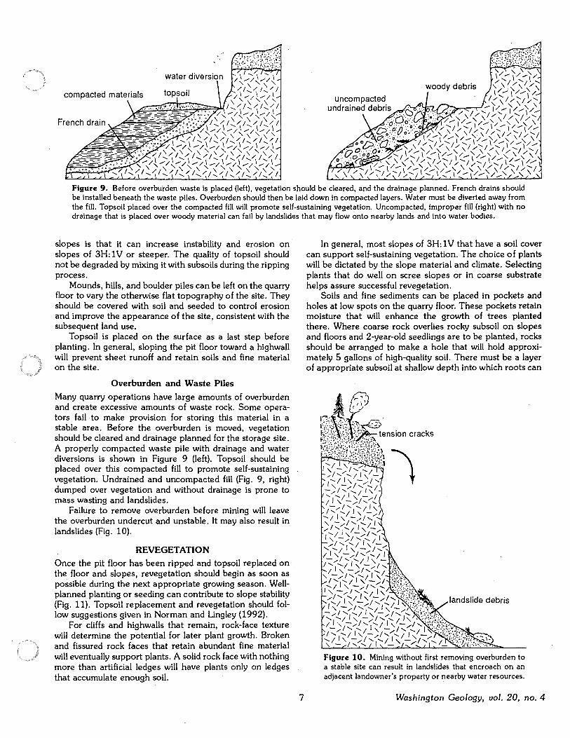
woody debris
Figure 9. Before overburden waste is placed (left), vegetation should be cleared, and the drainage planned. French drains should be installed beneath the waste piles. Overburden should then be laid down in compacted layers. Water must be diverted away from the fill. Topsoil placed over the compacted fill will promote self-sustaining vegetation. Uncompacted, improper fill (right) with no drainage that is placed over woody material can fail by landslides that may flow onto nearby lands and Into water bodies.
slopes is that it can increase instability and erosion on slopes of 3H: 1 V or steeper. The quality of topsoil should not be degraded by mixing it with subsoils during the ripping process.
Mounds, hills, and boulder piles can be left on the quarry floor to vary the otherwise flat topography of the site. They should be covered with soil and seeded to control erosion and improve the appearance of the site, consistent with the subsequent land use.
Top soil is placed on the surface as a last step before planting. In general, sloping the pit floor toward a highwall will prevent sheet runoff and retain soils and fine material on the site.
Overburden and Waste Piles
Many quarry operations have large amounts of overburden and create excessive amounts of waste rock. Some operators fail to make provision for storing this material in a stable area. Before the overburden is moved, vegetation should be cleared and drainage planned for the storage site. A properly compacted waste pile with drainage and water diversions is shown in Figure 9 (left). Topsoil should be placed over this compacted fill to promote self-sustaining vegetation. Undrained and uncompacted fill (Fig. 9, right) dumped over vegetation and without drainage is prone to mass wasting and landslides.
Failure to remove overburden before mining will leave the overburden undercut and unstable. It may also result in landslides (Fig. 10).
REVEGETATION Once the pit floor has been ripped and topsoil replaced on the floor and slopes, revegetation should begin as soon as possible during the next appropriate growing season. Wellplanned planting or seeding can contribute to slope stability (Fig. 11). Topsoil replacement and revegetation should follow suggestions given in Norman and Lingley (1992).
For cliffs and highwalls that remain, rock-face texture will determine the potential for later plant growth. Broken and fissured rock faces that retain abundant fine material will eventually support plants. A solid rock face with nothing more than artificial ledges will have plants only on ledges that accumulate enough soil.
7
In general, most slopes of 3H: 1 V that have a soil cover can support self-sustaining vegetation. The choice of plants will be dictated by the slope material and climate. Selecting plants that do well on scree slopes or in coarse substrate helps assure successful revegetation.
Soils and fine sediments can be placed in pockets and holes at low spots on the quarry floor. These pockets retain moisture that will enhance the growth of trees planted there. Where coarse rock overlies rocky subsoil on slopes and floors and 2-year-old seedlings are to be planted, rocks should be arranged to make a hole that will hold approximately 5 gallons of high-quality soil. There must be a layer of appropriate subsoil at shallow depth into which roots can
Figure 10. Mining without first removing overburden to a stable site can result in landslides that encroach on an adjacent landowner's property or nearby water resources.
Washington Geology, vol. 20, no. 4
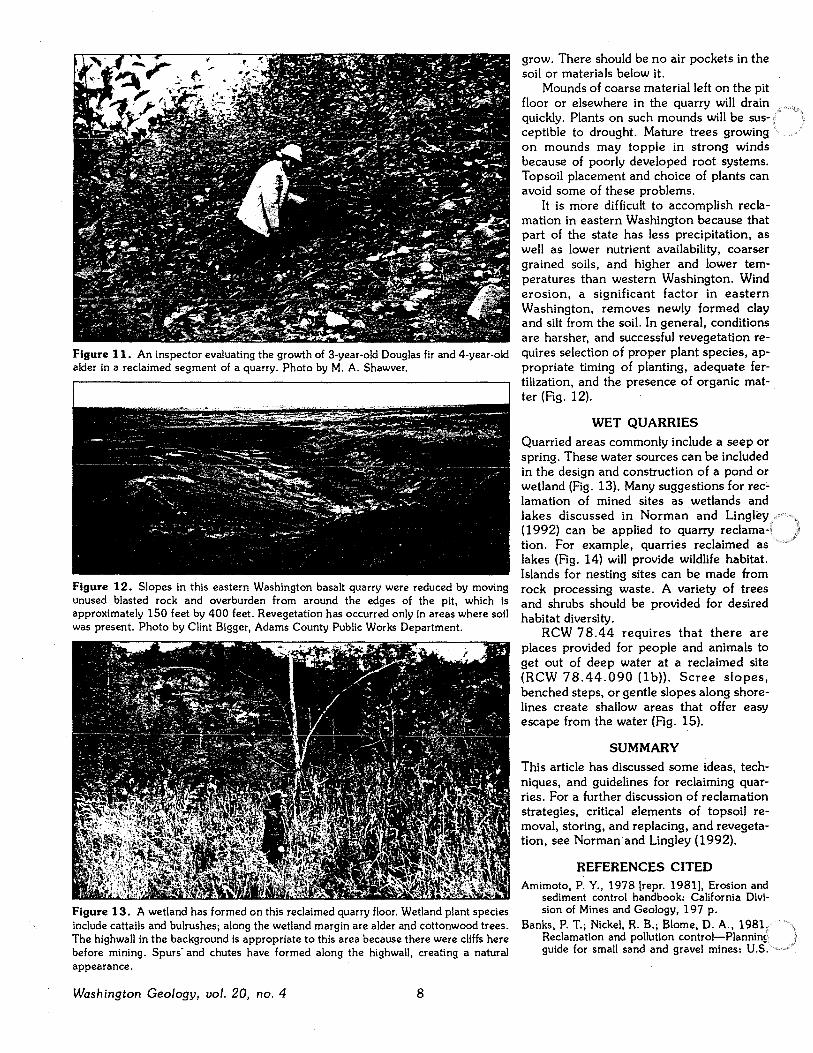
Figure 11. An inspector evaluating the growth of 3-year-old Douglas fir and 4-year-old alder in a reclaimed segment of a quarry. Photo by M.A. Shawver.
Figure 12. Slopes in this eastern Washington basalt quarry were reduced by moving unused blasted rock and overburden from around the edges of the pit, which is approximately 150 feet by 400 feet. Revegetation has occurred only in areas where soil was present. Photo by Clint Bigger, Adams County Public Works Department.
Figure 13. "A wetland has formed on this reclaimed quarry floor. Wetland plant species include cattails and bulrushes; along the wetland margin are alder and cottonwood trees. The highwall in the background is appropriate to this area because there were cliffs here before mining. Spurs· and chutes have formed along the highwall, creating a natural appearance.
Washington Geology, vol. 20, no. 4 8
grow. There should be no air pockets in the soil or materials below it.
Mounds of coarse material left on the pit floor or elsewhere in the quarry will drain quickly. Plants on such mounds will be susceptible to drought. Mature trees growing on mounds may topple in strong winds because of poorly developed root systems. Topsoil placement and choice of plants can avoid some of these problems.
It is more difficult to accomplish reclamation in eastern Washington because that part of the state has less precipitation, as well as lower nutrient availability, coarser grained soils, and higher and lower temperatures than western Washington. Wind erosion, a significant factor in eastern Washington, removes newly formed clay and silt from the soil. In general, conditions are harsher, and successful revegetation requires selection of proper plant species, appropriate timing of planting, adequate fertilization, and the presence of organic matter (Fig. 12).
WET QUARRIES Quarried areas commonly include a seep or spring. These water sources can be included in the design and construction of a pond or wetland (Fig. 13). Many suggestions for reclamation of mined sites as wetlands and lakes discussed in Norman and Lingley ( 1992) can be applied to quarry reclamation. For example, quarries reclaimed as lakes (Fig. 14) will provide wildlife habitat. Islands for nesting sites can be made from rock processing waste. A variety of trees and shrubs should be provided for desired habitat diversity.
RCW 78.44 requires that there are places provided for people and animals to get out of deep water at a reclaimed site {RCW 78.44.090 (lb)). Scree slopes, benched steps, or gentle slopes along shorelines create shallow areas that offer easy escape from the water (Fig. 15).
SUMMARY This article has discussed some ideas, techniques, and guidelines for reclaiming quarries. For a further discussion of reclamation strategies, critical elements of topsoil removal, storing, and replacing, and revegetation, see Norman and Lingley (1992).
REFERENCES CITED Amimoto, P. Y., 1978 [repr. 1981), Erosion and
sediment control handbook: California Division of Mines and Geology, 197 p.
Banks, P. T.; Nickel, R. B.; Blome, D. A., 1981. Reclamation and pollution control-Plannin~ guide for small sand and gravel mines: U.S.
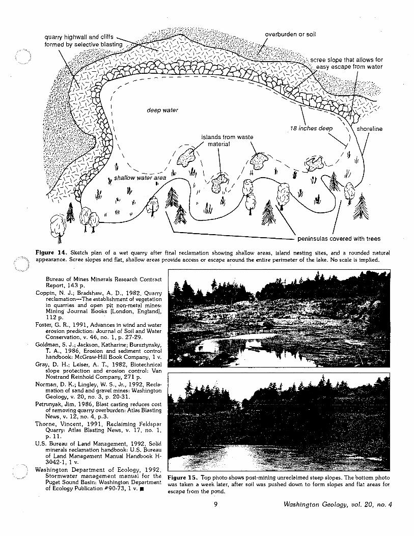
deep water
islands from waste
Figure 14. Sketch plan of a wet quarry after final reclamation showing shallow areas, island nesting sites, and a rounded natural appearance. Scree slopes and flat, shallow areas provide access or escape around the entire perimeter of the lake. No scale is implied.
Bureau of Mines Minerals Research Contract Report, 143 p.
Coppin, N. J.; Bradshaw, A. D., 1982, Quarry reclamation-The establishment of vegetation in quarries and open pit non-metal mines: Mining Journal Books [London, England], 112 p.
Foster, G. R., 1991, Advances in wind and water erosion prediction: Journal of Soil and Water Conservation, v. 46, no. 1, p. 27-29.
Goldman, S. J.; Jackson, Katharine; Bursztynsky, T. A., 1986, Erosion and sediment control handbook: McGraw-Hill Book Company, 1 v.
Gray, D. H.; Leiser, A. T., 1982, Biotechnical slope protection and erosion control: Van Nostrand Reinhold Company, 271 p.
Norman, D. K.; Lingley, W. S., Jr., 1992, Reclamation of sand and gravel mines: Washington Geology, v. 20, no. 3, p. 20-31.
Petrunyak, Jim, 1986, Blast casting reduces cost of removing quarry overburden: Atlas Blasting News, v. 12, no. 4, p.3.
Thorne, Vincent, 1991, Reclaiming Feldspar Quarry: Atlas Blasting News, v. 17, no. 1, p. 11.
U.S. Bureau of Land Management, 1992, Solid minerals reclamation handbook: U.S. Bureau of Land Management Manual Handbook H-3042-1, 1 v.
Washington Department of Ecology, 1992, Stormwater management manual for the Puget Sound Basin: Washington Department of Ecology Publication #90-73, 1 v. •
Figure 15. Top photo shows post-mining unreclaimed steep slopes. The bottom photo was taken a week later, after soil was pushed down to form slopes and flat areas for escape from the pond.
9 Washington Geology, vol. 20, no. 4

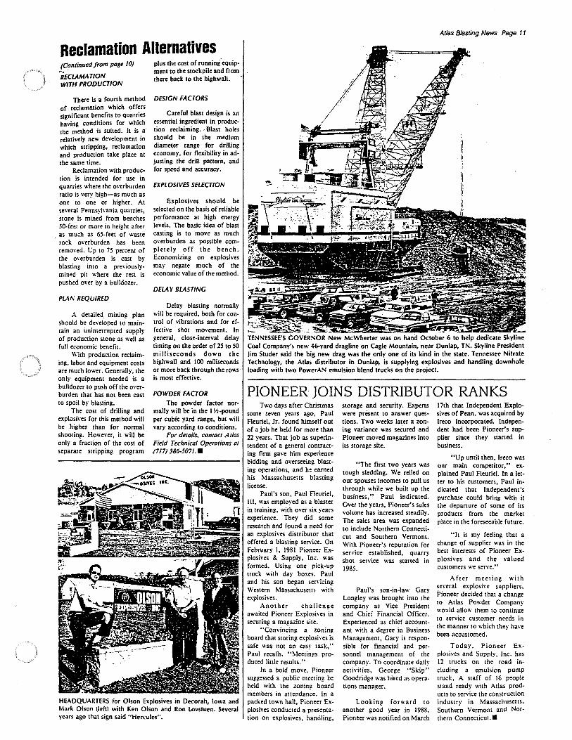
Reclamation Alternatives (Continued from page JO)
RECLAMATION WITH PRODUCTION
There is a fourth method of reclamation which offers significant benefits to quarries having conditions for which the method is suited. It is a relatively new development in which stripping, reclamation and production take place at the same time.
Reclamation with production is intended for use in quarries where the overburden ratio is very high-as much as one 10 one or higher. At several Pennsylvania quarries, stone is mined from benches 50-feet or more in height after as much as 65-feet of waste rock overburden has been remo,·ed. t.:p 10 75 percent of the overburden is cast by blasting into a previouslymined pit where the rest is pushed over by a bulldozer.
PLA/\: REQUIRED
A detailed mining plan should be developed to maintain an uninterrupted supply of production stone as well as full economic benefit.
With production reclaiming. labor and equipment costs are much lower. Generally, the only equipment needed is a bulldozer to push off the overburden that has not been cast to spoil by blasting.
The cost of drilling and explosh·es for this method will be higher than for normal shooting. However, it will be· only a fraction of the cost of separate stripping program
plus the cost of running"equip· ment to the stockpile and from there back to the highwall.
DESIGN FACTORS
careful blast design is an essential ingredient in production reclaiming .. -.Blast holes should be in the medium diame\er range for drilling economy, for flexibility in adjusting the drill pattern, and for speed and accuracy.
EXPLOSIVES SELECTION
Explosives should be selected on the basis of reliable performance at high energy levels. The basic idea of blast casting is to move as much o,·erburden as possible complete I y off the bench. Economizing on explosives may negate much of the economic value of the method.
DELAY BLASTING
Delay blasting normally will be required, both for control of vibrations and for effective shot movement. In general, close-interval delay timing on the order of 25 to 50 milliseconds down the highwall and JOO miliseconds or more back through the rows is most effective.
POWDER FACTOR
The powder factor normally will be in the I \!,-pound per cubic yard range, but will vary according to conditions.
For details, contact Atlas Field Technical Operations at . (717) 386-5071 ••
HEADQUARTERS for Olson Explosives in Decorah, Iowa and Mark Olson (left) with Ken Olson and Ron lovstuen. Several years ago that sign said "Hercules".
Atlas Blasting News Page 11
;!::'~~'7~~---C 'SL ~· TENNESSEE'S GOVERSOR New McWherter was on hand October 6 to help dedicate Skyline Coal Company's new 46-yard dragline on Cagle Mountain, near Dunlap, TN. Skyline President Jim Studer said the big new drag was the only one of its kind in the state. Tennessee Nitrate Technology, the Atlas distributor in Dunlap, is supplying explosives and handling downhole loading with two PowerAS emulsion blend trucks on the project.
PIONEER JOINS DISTRIBUTOR RANKS Two days after Christmas
some seven years ago, Paul Fleuriel, Jr. found himself out of a job he held for more than 22 years. That job as superintendent of a general contracting firm gave him experience bidding and overseeing blast· ing operations, and he earned his Massachusetts blasting license.
Paul's son, Paul Fleuriel, III, was employed as a blaster in training, with over six years experience. They did some research and found a need for an explosives distributor that offered a blasting senice. On February I, 1981 Pioneer Explosives & Supply, Inc. was formed. Using one pick-up truck with day boxes, Paul and his son began sen·icing Western Massachuseus "ith explosives.
Another challenge awaited Pioneer Explosives in securing a magazine site.
"Convincing a zoning board that storing explosh·es is safe was not an easy task," Paul recalls. "'.\leetings produced little results."
In a bold move. Pioneer suggested a public meeting be held with the zoning board members in auendance. In a packed town hall, Pioneer Explosives conducted a presentation on explosives, handling,
storage and security. Experts were present to answer ques· tions. Two weeks later a zon· ing variance was secured and Pioneer moved magazines into its storage site .
"The first two years was tough sledding. We relied on our spouses incomes to pull us through while we built up the business," Paul indicated. Over the years, Pioneer's sales volume has increased steadily. The sales area was expanded to include Northern Connecti· cut and Southern Vermont. With Pioneer's reputation for service established, quarry shot service was started in 1985.
Paul's son-in-law Gary Longley was brought into the company as Vice President and Chief Financial Officer. Experienced as chief account· ant with a degree in Business Management, Gary is responsible for financial and personnel management of the company. To coordinate daily activities, George "Skip" Goodridge was hired as operations manager.
Looking forward to another good year in 1988, Pioneer was notified on March
17th that Independent Explosives of Penn. was acquired by lreco Incorporated. lndepen· dent had been Pioneer's supplier since they started in business.
"Up until then, lreco was our main competitor," explained Paul Fleuriel. In a letter 10 his customers, Paul indicated that lndependent's purchase could bring with it the departure of some of its products from the market place in the foreseeable future.
"It is my feeling that a change of supplier was in the best interests of Pioneer Explosives and the valued customers we serve."
After meeting with several explosive suppliers, Pioneer decided that a change 10 Atlas Powder Company would allow them to continue to service customer needs in the manner to which they have been accustomed.
Today, Pioneer Ex· plosives and Supply, Inc. has 12 trucks on the road including a emulsion pump truck, A staff of 16 people stand ready with Atlas prod· ucts to sen·ice the construction industry in Massachuse11s, Southern Vermont and Northern Connecticut.•
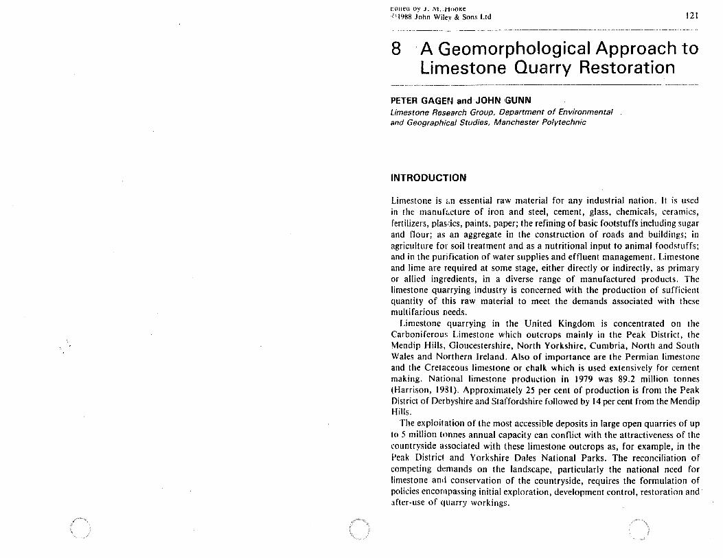
1:011eu ny J. 1\1. HooKe ·r'l988 John Wiley & Sons Ltd 121
8 · A Geomorphological Approach to Limestone Quarry Restoration
PETER GAGEra and JOHN GUNN Limestone Research Group, Department of Environmental and Geographical Studies, Manchester Polytechnic
INTRODUCTION
Limestone is .. n essential raw material for any industrial nation. It is used in the manufc,cture of iron and steel, cement, glass, chemicals, ceramics, rertilizers, plasdcs, paints, paper; the refining of basic footstuffs including sugar and nour; as an aggregate in the construction of roads and buildings; in agriculture for soil treatment and as a nutritional input to animal foodstuffs; and in the purification of water supplies and effluent management. Limestone and lime are required at some stage, either directly or indirectly, as primary or allied ingredients, in a diverse range of manufactured products. The limestone quarrying industry is concerned with the production of sufficient quantity of this raw material to meet the demands associated with these multifarious needs.
Limestone quarrying in the United Kingdom is concentrated on the Carboniferous Limestone which outcrops mainly in the Peak District, the Mendip Hills, Gloucestershire, North Yorkshire, Cumbria, North and South Wales and Northern Ireland. Al!>o of importance are the Permian limestone and the Cretaceous limestone or chalk which is used extensively for cement making. National limestone production in 1979 was 89.2 million tonnes (Harrison, 1981). Approximately 25 per cent of production is from the Peak District of Derbyshire and Staffordshire followed by 14 per cent from the Mendip Hills.
The exploit at ion of the most accessible deposits in large open quarries of up to 5 million tonnes annual capacity can conflict with the attractiveness of the countryside associated with these limestone outcrops as, for example, in the Peak District and Yorkshire Dales National Parks. The reconciliation of competing demands on the landscape, particularly the national need for limestone and conservation of the countryside, requires the formulation of policies encompassing initial exploration, development control, restoration and arter-use of quarry workings.
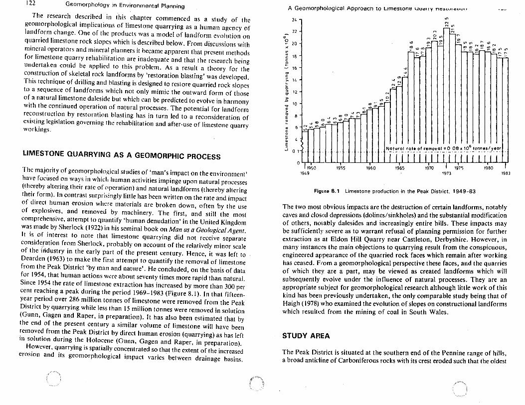
122 Geomorphology in Environmental Planning
The research described in this chapter commenced as a study of the geomorphological implications of limestone quarrying as a human agency of landform change. One of the products was a model of landform evolution on quarried limestone rock slopes which is described below. From discussions with mineral operators and mineral planners it became apparent that present methods for limestone quarry rehabilitation are inadequate and that the research being undertaken could be applied to this problem. As a result a theory for the construction of skeletal rock landforms by 'restoration blasting' was developed. This technique of drilling and blasting is designed to restore quarried rock slopes to a sequence of landforms which not only mimic the outward form of those of a natural limestone daleside but which can be predicted to evolve in harmony with the continued operation of natural processes. The potential for landform reconstruction by restoration blasting has in turn led to a reconsideration of existing legislation governing the rehabilitation and after-use of limestone quarry workings.
LIMESTONE QUARRYING AS A GEOMORPHIC PROCESS
The majority of geomorphological studies of 'man's impact on the environment' have focused on ways in whicli human activities impinge upon natural processes (thereby altering their rate of Pperation) and natural landforms (thereby altering their form). In contrast surprisingly little has been written on the rate and impact of direct human erosion where materials are broken down, often by the use of explosives, and removed by machinery. The first, and still the most comprehensive, attempt to quantify 'human denudation' in the United Kingdom was made by Sherlock ( 1922) in his seminal book on Man as a Geological Agent. It is of interest to note that limestone quarrying did not receive separate consideration from Sherlock, probably on account of the relatively minor scale of the iridustry in the early part of the present century. Hence, it was left to Dearden (1963) to make the first attempt to quantify the removal of limestone from the Peak District 'by man and nature'. He concluded, on the basis of data for 1954, that human actions w~re about seventy times more rapid than natural. Since 1954 the rate of limestone extraction has increased by more than 300 per cent reaching a peak during the period 1969-1983 (Figure 8.1 ). In that fifteenyear period over 286 million tonnes of limestone were removed from the Peak District by quarrying while less than 15 million tonnes were removed in solution (Gunn, Gagen and Raper, in preparation). It has also been estimated that by the end of the present century a similar volume of limestone will have been removed from the Peak District by direct human erosion (quarrying) as has left in solution during the Holocene (Gunn, Gagen and Raper, in preparation).
However, quarrying is spatially concentrated so that the extent of the increased erosion and its geomorphological impact varies between drainage basins.
A Geomorphological Approach to Limestone uuarry nt:::,,v,o"v"
2L
22
"' ~ 20
" ., <II 18 C C
.e - 16 c,, C
> 14 ... ... 0 :, 12 CT
>-D
'O 10 .,
> 0
8 E "' ... ., C
.e ., 4 ., s .J 0 1
0 I 1950 1955 1960
1949
....
.... a, ~
-, N
N~
M
M ~ U,
tD (Tl,--, O'I
t;!. ~(!) ....
"' N N Ill
N r--
No~~~~'. i:_o_t_! _o_f .r!m_o:--_o_t_=.~ _o_e ~ )~~ _!o~n!.s.ty_e_o~
1973
Figl!re 8.1 Limestone production in the Peak District, 1949-83
1983
The two most obvious impacts are the destruction of certain landforms, notably caves and closed depressions (dolines/sinkholes) and the substantial modification of others, nolably dalesides and increasingly entire hills. These impacts may be sufficiently severe as to warrant refusal of planning permission for further extraction as at Eldon Hill Quarry near Castleton, Derbyshire. However, in many instances the main objections to quarrying result from the conspicuous, engineered appearance of the quarried rock faces which remain after working has ceased. Frnm a geomorphological perspective these faces, and the quarries of which they are a part, may be viewed as created landforms which will subsequently evolve under the influence of natural processes. They are an appropriate subject for geomorphological research although little work of this kind has been previously undertaken, the only comparable study being that of Haigh (1978) who examined the evolution of slopes on constructional landforms which resulted from the mining of coal in South Wales.
STUDY AFIEA
The Peak District is situated at the southern end of the Pennine range of hills, a broad anticline of Carboniferous rocks with its crest eroded such that the oldest
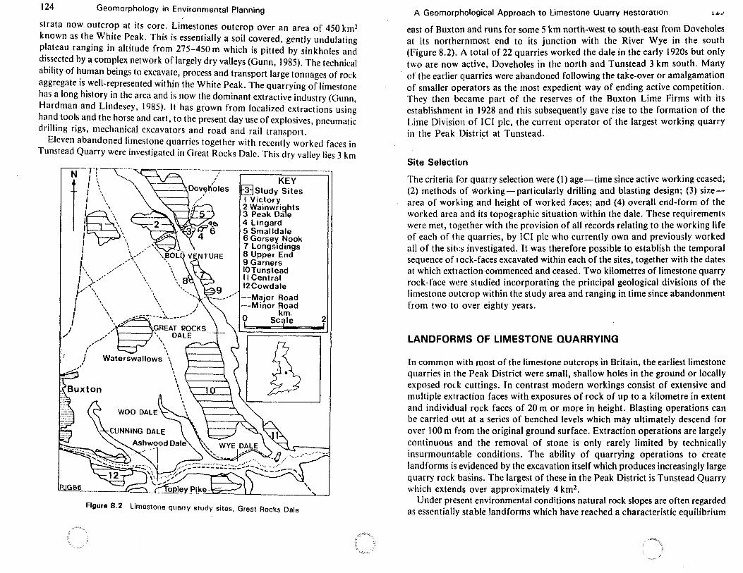
124 Geomorphology in Environmental Planning
' strata now outcrop at its core. Limestones outcrop over an area of 450 km 2
known as the White Peak. This is essentially a soil covered, gently undulating plateau ranging in altitude from 275-450 m which is pitted by sinkholes and dissected by a complex network of largely dry valleys (Gunn, 1985). The technical ability of human beings to excavate, process and transport large tonnages of rock aggregate is well-represented within the White Peak. The quarrying of limestone has a long history in the area and is now the dominant extractive industry (Gunn, Hardman and Lindesey, 1985). It has grown from localized extractions using hand tools and the horse and cart, to the present day use of explosives, pneumatic drilling rigs, mechanical excavators and road and rail transport.
Eleven abandoned limestone quarries together with recently worked faces in Tunstead Quarry were investigated in Great Rocks Dale. This dry valley lies 3 km
N r. I ;
I~ ------~--··7-·--------------------
KEY \-----....J. Dov~t\oles
I \ I \ , I I,, I ,-·\
f ,, ' , ' \ ,., '
I \,, ,.,,,,' \\
\ .... ' -~ ' I ,,,""', \ ,,, \ ' , \ \ / , \" \, ,,/ , \ ,,-.-... .:._ _____ _
I \~/-, GREAT ROCKS I / \ DALE
/ ,," \ ~ -- ' ,,' '\
/ Waterswallows \ I \ ,, I
~ \ ', ' ' ' ' ' I
\
WStudy Sites I Victory 2 Wainwrights 3 Peak Dale 4 Lingard 5 Smalldale 6 Gorsey Nook 7 Longsidings 8 Upper End 9 Garners IOTunstead 11 Central 12Cowdale
--Major Road --Minor Road
km. Scale
I
b
Figure 8.2 Limestone quarry study sites. Great Rocks Dale
2 __,
A Geomorphological Approach to Limestone Uuarry Hestorauon .... ., east of Buxton and runs for some 5 km north-west to south-east from Doveholes at its northernmost end to its junction with the River Wye in the south (Figure 8.2). A total of 22 quarries worked the dale in the early 1920s but only two are now active, Doveholes in the north and Tunstead 3 km south. Many of the earlier quarries were abandoned following the take-over or amalgamation of smaller operators as the most expedient way of ending active competition. They then became part of the reserves of the Buxton Lime Firms with its establishment in 1928 and this subsequently gave rise to the formation of the Lime Division of ICI pie, the current operator of the largest working quarry in the Peak District at Tunstead.
Site Selection
The criteria for quarry selection were (I) age-time since active working ceased; (2) methods of working-particularly drilling and blasting design; (3) sizearea of working and height of worked faces; and (4) overall end-form of the worked area and its topographic situation within the dale. These requirements were met, together with the provision of all records relating to the working life of each of the quarries, by ICI pie who currently own and previously worked all of the siti:s investigated. It was therefore possible to establish the temporal sequence of rock-faces excavated within each of the sites, together with the dates at which extraction commenced and ceased. Two kilometres of limestone quarry rock-face were studied incorporating the principal geological divisions of the limestone outcrop within the study area and ranging in time since abandonment from two to over eighty years.
LANDFORMS OF LIMESTONE QUARRYING
In common with most of the limestone outcrops in Britain, the earliest limestone quarries in the Peak District were small, shallow holes in the ground or locally exposed rock cuttings. In contrast modern workings consist of extensive and multiple extraction faces with exposures of rock of up to a kilometre in extent and individual rock faces of 20 m or more in height. Blasting operations can be carried out at a series of benched levels which may ultimately descend for over I 00 m from the original ground surface. Extraction operations are largely continuous and the removal of stone is only rarely limited by technically insurmountable conditions. The ability of quarrying operations to create landforms is evidenced by the excavation itself which produces increasingly large quarry rock basins. The largest of these in the Peak District is Tunstead Quarry which extends over approximately 4 km2•
Under present environmental conditions natural rock slopes are often regarded as essentially stable landforms which have reached a characteristic equilibrium
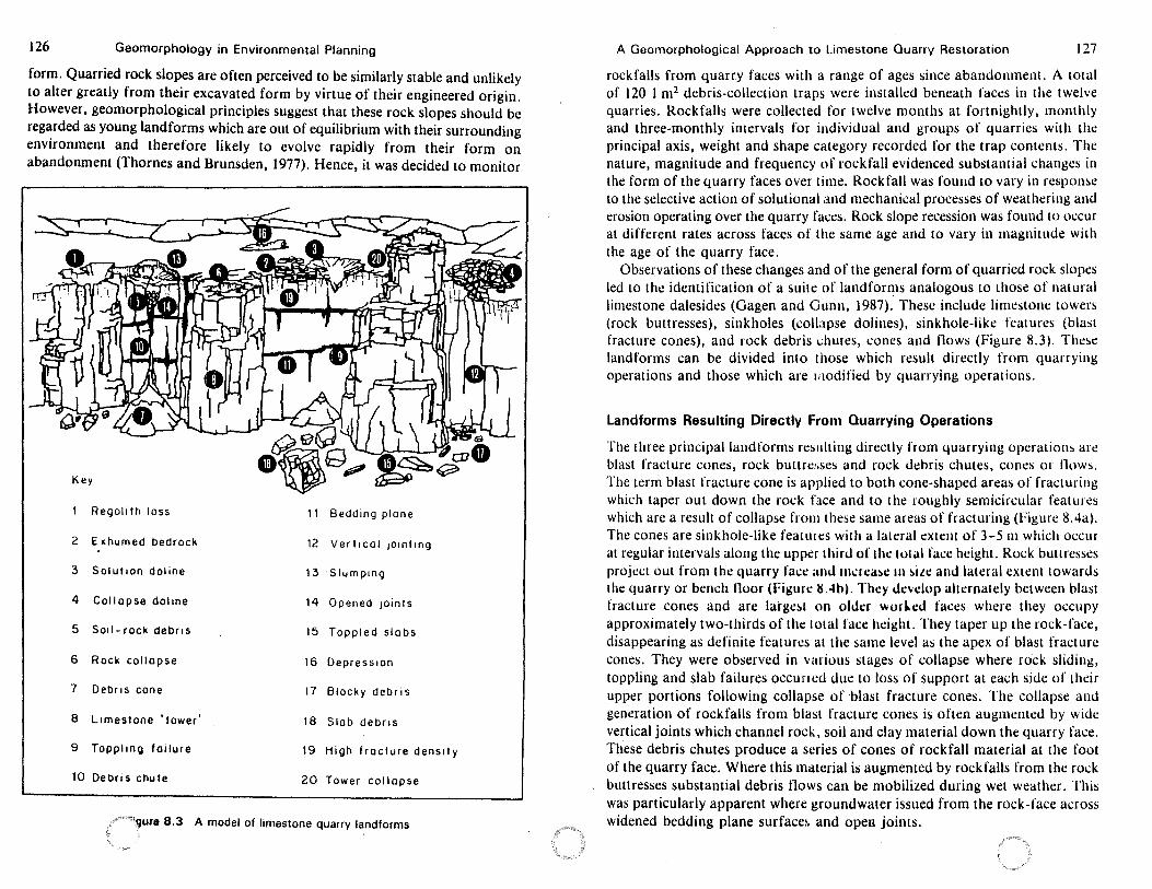
126 Geomorphology in Environmental Planning
form. Quarried rock slopes are often perceived to be similarly stable and unlikely to alter greatly from their excavated form by virtue of their engineered origin. However, geomorphological principles suggest that these rock slopes should be regarded as young landforms which are out of equilibrium with their surrounding environment and therefore likely to evolve rapidly from their form on abandonment (Thornes and Brunsden, 1977). Hence, it was decided to monitor
Key
Rego11th loss 11 Bedding plane
2 Exhumed bedrock 12 Vertical 101nt1ng
3 Solution doline 13 Slumping
4 Collapse doline 14 Opened Joints
5 Soil-rock debris 15 Toppled slabs
6 Rock collapse 16 Depression
7 Debris cone 17 Blocky debris
8 Limestone 'tower' 18 Slob debris
9 Topplino failure 19 High fracture density
10 Debris chute 20 Tower collapse
'"'"'qure 8.3 A model of limestone quarry landforms
A Geomorphological Approach to Limestone Quarry Restoration 127
rockfalls from quarry faces with a range of ages since abandonment. A total of 120 1 m2 debris-collection traps were installed beneath faces in the t we Ive quarries. Rockfalls were collected for twelve months at forrnigluly, monthly and three-monthly intervals for individual and groups of quarries with the principal axis, weight and shape category recorded for the trap contents. The nature, magnitude and frequency of rockfall evidenced substantial changes in the form of the quarry faces over time. Rockfall was found to vary in response to the selective action of solutional and mechanical processes of weathering and erosion operating over the quarry faces. Rock slope recession was found to occur at different rates across faces of the same age and to vary in magnitude with the age of the quarry face.
Observations of these changes and of the general form of quarried rock slopes led to the identification of a suite of landforms analogous to those of natural limestone dalesides (Gagen and Gunn, 1987). These include limestone towers (rock buttresses), sinkholes (collapse dolines), sinkhole-like features (blas1 fracture cones), and rock debris l:hutes, cones and flows (Figure 8.3). These landforms can be divided into those which result directly from quarrying operations and those which are 111odified by quarrying operations.
Landforms Resulting Directly From· Quarrying Operations
The three principal landforms res11lting directly from quarrying opera1ions are blast fracture cones, rock buttresses and rock debris chutes, cones or flows. The term blast fracture cone is applied to both cone-shaped areas of fracturing which taper out down the rock face and to the roughly semidrcular features which are a result of collapse from these same areas of fracturing (Figure 8.4a). The cones are sinkhole-like features with a laleral extem of 3-5 m which occur at regular intervals along the upper third of the total face height. Rock buuresses project out from 1he quarry face and incrca!>c Ill !)iLe and lateral extent towards 1he quarry or bench lloor (Figure 8.4b). They develop aherna1ely between blast fracture cones and are large!)t on older wor~ed fai.;es where they occupy approximately two-thirds of the 101al face height. They taper up the rock-face, disappearing as definite features at the same level as the apex of blast fracture cones. They were observed in various stages of collapse where rock sliding, toppling and slab failures occuned due to loss of support at each side of their upper portions following collapse of blast fracture cones. The collapse and generation of rockfalls from blast fracture cones is oflen augmented by wide vertical joints which channel rock, soil and clay material down the quarry face. These debris chutes produce a series of cones of rockfall material at the foot of the quarry face. Where this material is augmented by rockfalls from the rock buttresses substantial debris tlows can be mobilized during wet weather. This was particularly apparent where groundwater issued from the rock-face across widened bedding plane surface~ and open joints.
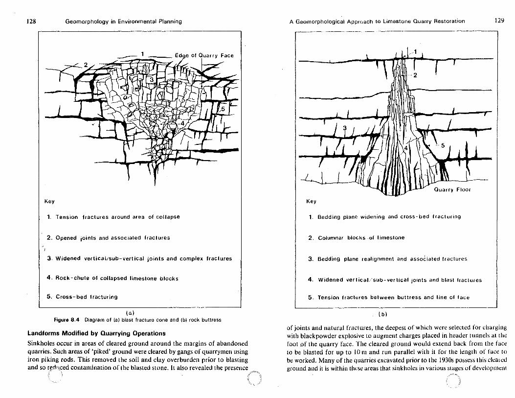
128 Geomorphology in Environmental Planning
Key
1. Tension fractures around area of collapse
2. Opened joints and associated fractures
3. Widened vertical/sub-vertical joints and complex fractures
4. Rock-chute of collapsed limestone blocks
5. Cross-bed fracturing
(al Figure 8.4 Diagram of (a) blast fracture cone and (b) rock buttress
Landforms Modified by Quarrying Operations
Sinkholes occur in areas of cleared ground around the margins of abandoned quarries. Such areas of 'piked' ground were cleared by gangs of quarrymen using iron piking rods. This removed the soil and clay overburden prior to blasting and so r!,!dq~ed contamination of the blasted stone. It also revealed the presence
A Geomorphological Approach to Limestone Quarry Restoration 129
-2
.. ,L,
,_•11 -~ Floor
Key
1. Bedding plane widening and cross-bed fracturing
2. Columnar blocks .of limestone
3. Bedding plane realignment and associated fractures
4. Widened vertical/sub-vertical joints and blast fractures
5. Tension fractures between buttress and line of face
---( b)
of joints and natural fractures, the deepest of which were selected for charging with blackpowder explosive to augment charges placed in header rnnnels at the foot of the quarry face. The cleared ground would extend back from the face to be blasted for up to 10 m and run parallel with it for the leng1h of face to be worked. Many of the quarries excavated prior to the 1930s possess this clea1t:d ground and it is within tlwse areas that sinkholes in various stages of devclopmi::nl
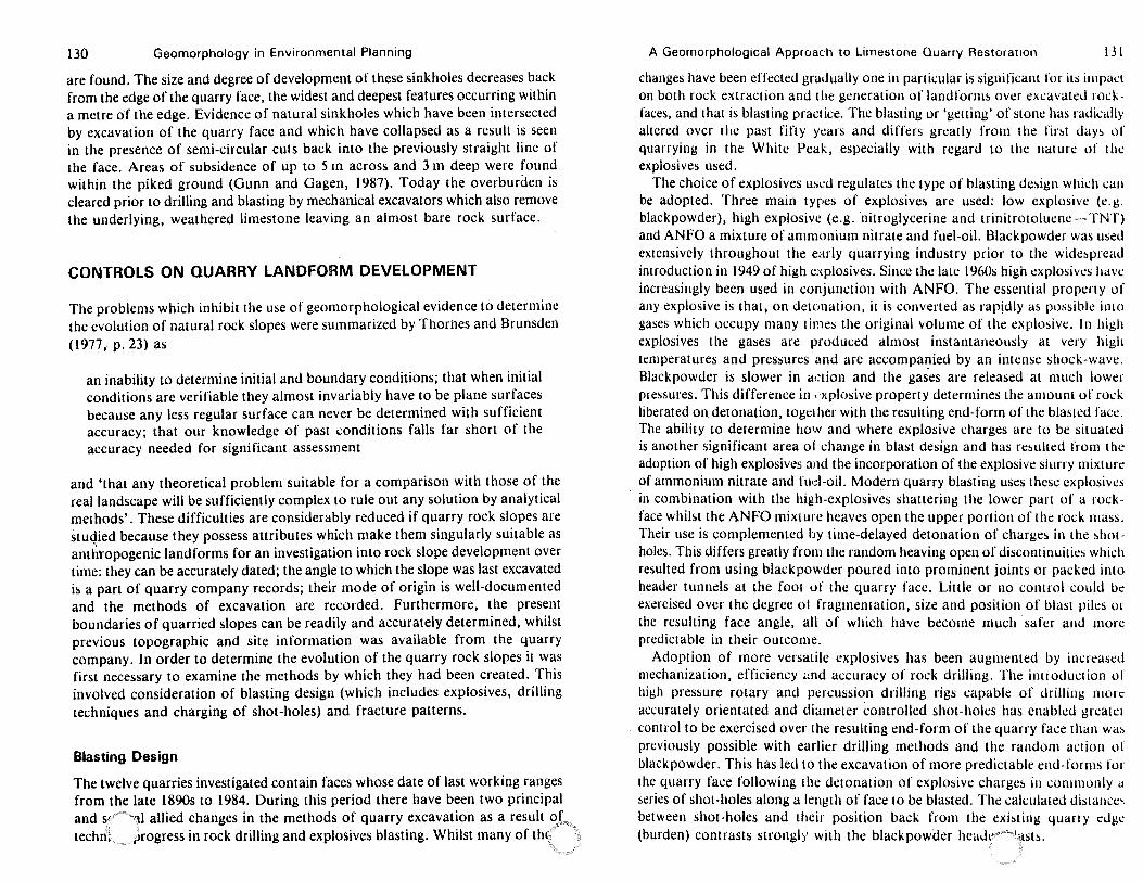
130 Geomorphology in Environmental Planning
are found. The size and degree of development of these sinkholes decreases back from the edge of the quarry face, the widest and deepest features occurring within a metre of the edge. Evidence of natural sinkholes which have been intersected by excavation of the quarry face and which have collapsed as a result is seen in the presence of semi-circular cuts back into the previously straight line of the face. Areas of subsidence of up to 5 m across and 3 m deep were found within the piked ground (Gunn and Gagen, 1987). Today the overburden is cleared prior to drilling and blasting by mechanical excavators which also remove the underlying, weathered limestone leaving an almost bare rock surface.
CONTROLS ON QUARRY LANDFORM DEVELOPMENT
The problems which inhibit the use of geomorphological evidence to determine the evolution of natural rock slopes were summarized by Thornes and Brunsden (1977, p. 23) as
an inability to determine initial and boundary conditions; that when initial conditions are verifiable they almost invariably have to be plane surfaces because any less regular surface can never be determined with sufficient accuracy; that our knowledge of past conditions falls far short of the accuracy needed for significant assessment
and 'that any theoretical problem suitable for a comparison with those of the real landscape will be sufficiently complex to rule out any solution by analytical methods'. These difficulties are considerably reduced if quarry rock slopes are stuqied because they possess attributes which make them singularly suitable as anthropogenic landforms for an investigation into rock slope development over time: they can be accurately dated; the angle to which the slope was last excavated is a part of quarry company records; their mode of origin is well-documented and the methods of excavation are recorded. Furthermore, the present boundaries of quarried slopes can be readily and accurately determined, whilst previous topographic and site information was available from the quarry company. In order to determine the evolution of the quarry rock slopes it was first necessary to examine the methods by which they had been created. This involved consideration of blasting design (which includes explosives, drilling techniques and charging of shot-holes) and fracture patterns.
Blasting Design
The twelve quarries investigated contain faces whose date of last working ranges from the late 1890s to 1984. During this period there have been two principal and S' H"·, 11 allied changes in the methods of quarry excavation as a result °',[*~ techn, .,rogress in rock drilling and explosives blasting. Whilst many of thl ·
A Geomorphological Approach to Limestone Quarry Restoration 131
changes have been effected gradually one in partkular is significant for its i111pact on both rock extraction and tile generation of landforms over excavated rockfaces, and that is blasting practice. The blasting or 'getting' of stone has radically altered over rlie past fifty years and differs greatly from the fir!>t day!> of quarrying in the White Peak, especially with regard to the nature of the explosives used.
The choice of explosives usl:d regulates the type of blasting de!>ign whid1 can be adopted. Three main types of explosives are used: low explosive (e.g. blackpowder), high explosive (e.g. nitroglycerine and trinitrotoluene-TNT) and ANFO a mixture of ammonium nitrate and fuel-oil. Blackpowder was used extensively throughout the early quarrying industry prior to the wide~pread introduction in 1949 of high explosives. Since the late 1960s high explosives have increasingly been used in conjunction with ANFO. The essemial property of any explosive is that, on detonation, il is converted as rapidly as possible into gases which occupy many times the original volume of the explosive. In high explosives the gases are produced almosr instantaneously at very high temperatures and pressures and are accompa1_1ied by an intense shock-wave. Blackpowder is slower in a,:tion and the gases are released at much lower pressures. This difference in , xplosive property determines the amount of rock liberated on detonation, together with the resulting end-form of the blasted face. The ability to determine how and where explosive charges are to be situated is another significant area of change in blast design and has resulted from the adoption of high explosives and the incorporation of the explosive siurry mixture of ammonium nitrate and fud-oil. Modern quarry blasting uses these explosive!> in combination with the high-explosives shattering the lower part of a rockface whilst the ANFO mixture heaves open the upper portion of the rock mass. Their use is complemented by time-delayed detonation of charges in the shotholes. This differs greatly from the random heaving open of discontinuities which resulted from using blackpowder poured into prominent joints or packed into header tunnels at the fool of the quarry face. Little or no control could be exercised over the degree ol fragmentation, size and position of blast piles or the resulting face angle, all of which have become much safer and more predictable in their outcome.
Adoption of more versatile explosives has been augmented by increased mechanization, efficiency .:nd accuracy of rock drilling. The introduction of high pressure rotary and percussion drilling rigs capable of drilling more accurately orientated and diameter controlled shot-holes has enabled greate1 control to be exercised over the resulting end-form of the quarry face than wa~ previously possible with earlier drilling methods and the random action of blackpowder. This has Jed to the excavation of more predictable end-forms for the quarry face following the detonation of explosive charges in commonly a series of shot-holes along a length of face to be blasted. The cakulated dista11ce, between shot-holes and their position back from the existing quarry edge (burden) contrasts strongly with the black powder head1i"" 'asts.
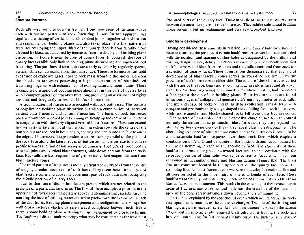
132 Geomorphology in Environmental Planning -fracture Patterns
Rockfalls were found to be most frequent from three areas of the quarry face each with distinct patterns of rock fracturing. It was further apparent that significant widening of vertical and sub-vertical joints, together with distortion and realignment of bedding planes had also taken place. The first pattern of fractures occupying the upper third of the quarry faces is considerably more affected by blast, as evidenced by increased fracture density and bedding plane distortion, particularly near the crest of quarry faces. In contrast, the foot of quarry faces exhibit only limited bedding plane disturbance and much reduced fracturing. The positions of shot-holes are clearly evidence by regularly spaced, venical white scorch marks along the quarry face. These are formed by the rapid expansion of explosive gases into the rock mass from the shot-holes. Between the shot-holes are areas possessing a high concentration of blast-induced fracturing, together with enhancement of existing natural discontinuities. There is complete disruption of bedding plane alignment in this part of qu_arry faces with a complex pattern of cross-bed fracturing producing an assortment of highly unstable and irregularly orientated blocks of limestone.
A second pattern of fractures is associated with rock buttresses. This consists of only limited bedding plane distortion but with a combination of increased vertical blast fractures and tension fracwring. The bases of rock buttresses possess prominent widened joints running vertically up the centre of the buuress in conjunction with similarly aligned vertical blast fractures. These can extend to over half the face height at their maximum extent towards the centre of the buttress but are reduced in both length, spacing and depth into the face towards the edges of buttresses. Large tension fractures occur parallel to the plane of the rock-face along the lateral edges of buttresses. This gives rise to a convex profiie towards the foot of buttresses as columnar-shaped blocks, produced by widened joints and vertical blast fractures, slide down and out from the rockface. Rockfalls are less frequent but of greater individual magnitude than from blast fracture cones.
The third pauern of fractures is radially orientated outwards from the centre of roughly circular scoops out of rock-faces. They occur beneath the apex of blast fracture cones and above the uppermost part of rock buttresses, occupying the middle portion of quarry faces.
Two further sets of discontinuities are present which are not related to the presence of a particular landform. The first of these occupies a position in the upper half of rock-faces immediately above the stemming-line, an arbitrary line marking the base of infilling material used to pack-down the explosives in each of the shot-holes. Bedding plane enlargement and realignment occurs together with cross-fractures which only rarely travel completely between beds. Below there is some bedding plane widening but no realignment or cross-fracturing. The fina·'"p~, of discontinuities occupy what may be considered as the least blast
A Geomorphological Approach to Limestone Quarry Restoration 133
fractured parts of the quarry face. These areas lie at the foot uf quarry faces between the outermost parts of rock buttresses. They exhibit substantial bedding plane widening but no realig11ment and very few cross-bed fractures.
Landform development
Having considered these comrols in relation to the quarry landfonn model it became clear that the position of certain landforms across worked faces accorded with the position and spacing of shot-holes as designated by the drilling and blasting design. Hence, debris collection traps were relocated beneath identified rock buttresses and blast fracture cones and rockfalls monitored from ead1 for a selection of quarry faces. These observations demonstrated that the lakral development of blast fracture cones across the rock-face was limited by l he presence of rock buttresses at either side. The extent of these buttresses varied with the age of the face, beinr more prominent across older faces and also over recently (less than two years) abandoned faces where blasting had excavated a face against the dip of the bedding planes. Blast fracture cones are found in various stages of collapse and generate differing magnitudes of rock falls. The size and shape of rocks t',11111d in the debris collection traps differed with elongate and predominantly wedge-shaped rocks falling from rock bullres~e~. whilst more angular and blocky-shaped rocks fell from blast fracture cones.
The pattern of shot-holes and their explosive charging are seen to ..:ontrol not only the nature of the production blast for which they are prepared bu1 alsu the further developmem of the quarry face if blasting is discon1inucd. The alternating sequence of bias! fracture cones and rock buttresses is found to be a characteristic landform sequence over those rock face~ which employ a combination of ANFO and dynamite in the blasting design, accompanied by the use of stemming in each of the shot-holes fired. The regularity of these landforms across a length of excavated face and their accordance with the recorded position of shot-holes was repeated across faces which had been excavated using similar dniling and blasting designs (Figure 8.5). The blast fracture cones are located in the upper part of the quarry face above the stemming-line. No blast fracture cone was ~cen to develop beneath this line and all were restricted to the upper third of the total height of rock-face. These landforms are highly unstable and generate some of the earliest rockfalls from blasted faces on abandonment. This results in the widening of these cone-shaped areas of fractures across, down and back into the crest-line of the face. The apex of the cone rarely advances down beyond the stemming-liue.
This can be explained by the sequence of events which occurs across the rockface upon the detonation of the explosive charges. The aim of the drilling and blasting design is to excavali: safely the maximum amount of stone of the desired fragmentation into an easily removed blast pile, whilst leaving the rock-face in a condition suitable for further blasts to take place. The shot-holes arc charged
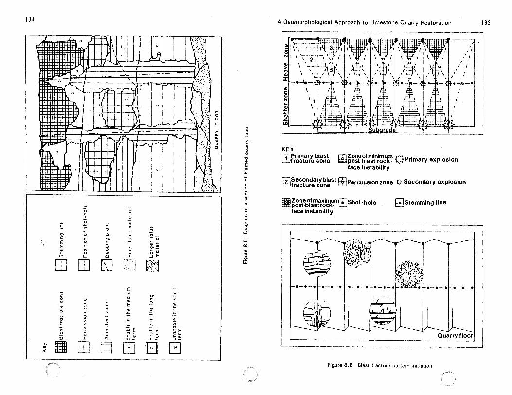
134
~ J
tlm. M r1 I
m-/1~ ~
Ql C =. O> C
E E ! U)
I I
Ql
0 .c.
0 .c. 1/) .... 0 C 0
"' 0 a..
Ql C 0
0.
O> C
-0 -0 Q)
(Il
,1
0 ~
Ql ... 0
E "' ::,
!? ~
Q)
C
IJ..
"' ..? o_ ... 0 ~ -Ql ~ O> Q) ~-0 0 ...J E
[I][IJ ~n~ w LJ ~
Q)
C 0 u
"' :,
u l?
"' 0
iii
Q)
C 0 N
C
9 1/)
"' ::, u ~
QJ
a..
Q)
C 0 ... -0 Q)
.c. u ~
0 u
U)
E ::,
-0 Q)
E Q)
.c.
= Q)
:0 E 0 ~
- Q) U) -
O> C
~ QJ
~
= Q)
:0 E 0 ... - Q) U) ...
... ~
0 .c. 1/)
Q)
.c. ... C
Q)
.D
Ee II) ...
C Q)
=>-,.. "' ::t:. 11 EE g ITJ B G
(
a: 0 0 .J u.
> a: a: <l :::)
0
1 .. i\ /:; .A
QJ
u IO .... ~ iii ::, 0-
"0 ~ II)
IO 1i .... 0 C: 0 ·;; u Ql II)
IO
0 E IO
Cl IO
i5
U'l Q) Q)
:5 C> ir
A Geomorphological Approach to Limestone Quarry Restoration
r---------------- ..
Q), C 0
"' Q) > l'O Q)
::c Q)
~ ... Q) .... ....
/; I
I I I
/ / / I •-le-•
I
I
m I ~LI i.!id·+-l~j++:l<~_I +-:l~f>f-±·btf):±±::l~J~
KEY r.;iPrimary blast ~fracture cone
rnzoneofminimum Y"f...p. 1 · ~post-blast rock- ¥ nmary exp os1on
face instability
i:;;::JSecondaryblast rnPercut..sionzone p Secondary explosion ~fracture cone D'J
8;lj8 Zone of maxilTII.STf;l Shot- hole tffl:l post-blast rock- L.J
face instability
·-·-·~·-·-·~·-·-·
Gstemming-line
•-•-•!-•-•-•
Quarry floor
Figure 8.6 Blast t,acture pattum 1nit1at1011
135
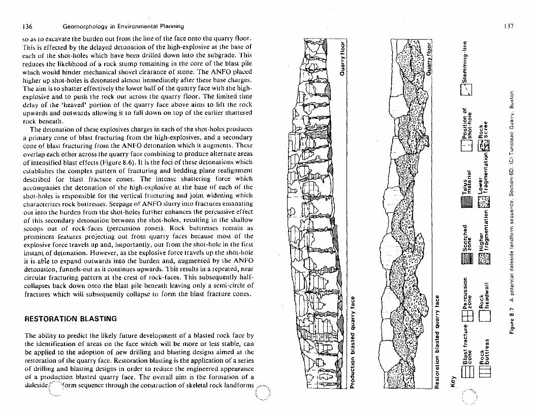
136 Geomorphology in Environmental Planning
~o a~ to excavate the burden out from the line of the face onto the quarry floor. This is effected by the delayed detonation of the high-explosive at the base of each of the shot-holes which have been drilled down into the subgrade. This reduces the likelihood of a rock stump remaining in the core of the blast pile which would hinder mechanical shovel clearance of stone. The ANFO placed higher up shot-holes is detonated almost immediately after these base charges. The aim is to shatter effectively the lower half of the quarry face with the highexplosive and to push the rock out across the quarry lloor. The limited time delay of the 'heaved' portion of the quarry face above aims to lift the rock upwards and outwards allowing it to fall down on top of the earlier shattered rock beneath.
The detonation of these explosives charges in each of the shot-holes produces a primary cone of blast fracturing from the high-explosives, and a secondary cone of bla~t fracturing from the ANFO detonation which it augments. These overlap each other across the quarry face combining to produce alternate areas of intensified blast effects (Figure 8.6). lt is the foci of these detonations which e~tablishes the complex pattern of fracturing and bedding plane realignment described for blast fracture cones. The intense shattering force which accompanies the detonation of the high-explosive at the base of each of the shot-holes is responsible for the vertical frncturing and joint widening which characterizes rock buttresses. Seepage of ANFO slurry into fracrures emanating out into the burden from the shot-holes furl her enhances the percussive effect of this secondary detonation between the shot-holes, resulting in the shallow scoop~ out of rock-faces (percussion zones). Rock buttresses remain as prominent features projecting out from quarry faces because most of the explosive force travels up and, importantly, out from the shot-hole in the first instan~ of detonation. However, as the explosive force travels up the shot-hole it is able to expand outwards into the burden and, augmented by the ANFO detonation, funnels-out as it continues upwards. This results in a repeated, near circular fracruring pattern at the crest of rock-faces. This subsequently halfcollapses back down onto the blast pile beneath leaving only a semi-circle of fractures which will subsequently collapse to form the blast fracture cones.
RESTORATION BLASTING
The ability to predict the likely future development of a blasted rock face by the identification of areas on the face which will be more or less stable, can be applied to the adoption of new drilling and blasting designs aimed at the restoration of the quarry face. Restoration blasting is the application of a series of drilling and blasting designs in order to reduce the engineered appearance of a production blasted quarry face. The ov.erall aim is the formation of a daleside 1
· form sequence through the construction of skeletal rock landforms
Cl) 0 Cl) ->, .... .. CII ::, CT
"O Cl) ... II) CII 1i C 0 ... 0 ::, "O 0 ..
Q.
Cl) 0 Cl) ->, .. .. Cl) ::, CT
"O Ill .... II) Cl)
:a C .2 .... Cl) ... 0 'lii >,
Cl) Q)
a: ~
Cl) C
I
Ol C
·e E Cl)
U)
D -041 c-oO ·-.C -' I ·iiio O.c
Q,.11)
B Cl) ·.:
1114) ::,_. -CII
~E
"O Cl) .c ecu oc 00 (/)N
Im C 0 'iii II) ::, OCI) ... c QIO Q.N
EB Cl) ... ::,
0 CII .. --Cl) Cllc .!!lo coo
[IJ
137
C 0 x :i al
c Cl) :u
..lO:CI) :i
O'- 0 OU "CJ a:(/) ro
~ ~
' "' C :i
a t-
:;:; S2 ,0 ... ci C
.... ~ (0
Cl) Ol c
3: CII 0 ·;;;
O'- 0 ...1- Q)
~ (/')
oi a CJ C:
C Q)
.S! :i c;
ia Q)
"' .... C §
• Cl)
ell E 0
.c CJl u CJl Cl) C ·- .... ~ :c-
~ Q)
:2 II) . Q)
iti 'O
ro ·;;; C:
iu Q)
3: 0 .:.: "O 0.
u Cl) 0 Cl)
<{
a:.£:
D "' (I)
Q)
5 Ol
u:: IJl II) Cl)
.....:'-u-o:i a:..c
§
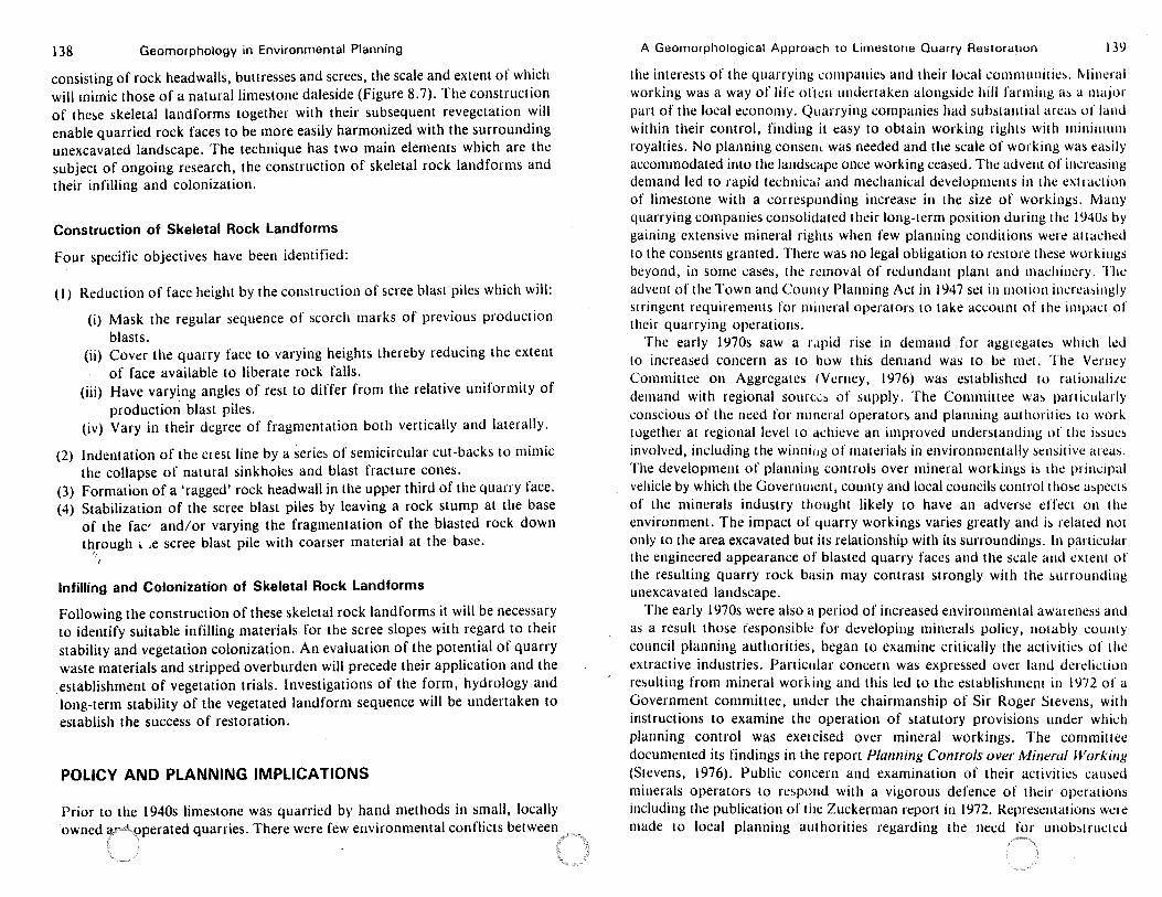
138 Geomorphology in Environmental Planning
consisting of rock headwalls, buttresses and screes, the scale and extent of which will mimic those of a natural limestone daleside (Figure 8. 7). The construction of the!.e skeletal landforms together with their subsequent revegetation will enable quarried rock faces to be more easily harmonized with the surrounding unexcavated landscape. The technique has two main elements which are the subject of ongoing research, the construction of skeletal rock landforms and their infilling and colonization.
Construction of Skeletal Rock Landforms
Four specific objectives have been identified:
(I) Reduction of face height by the construction of scree blast piles which will:
(i) Mask the regular sequence of scorch marks of previous production blasts.
(ii) Cover the quarry face to varying heights thereby reducing the extent of face available to liberate rock falls.
(iii) Have varying angles of rest to differ from the relative uniformity of production blast piles. .
(iv) Vary in their degree of fragmentation both vertically and laterally.
(2) Indentation of the crest line by a series of semicircular cut-backs to mimic the collapse of natural sinkholes and blast fracture cones.
(3) Formation of a 'ragged' rock headwall in the upper third of the quarry face. (4) Stabilization of the scree blast piles by leaving a rock stump at the base
of the fac, and/or varying the fragmentation of the blasted rock down t~rough i. ,e scree blast pile with coarser material at the base.
Infilling and Colonization of Skeletal Rock Landforms
Following the construction of these skeletal rock landforms it will be necessary to identify suitable infilling materials for the scree slopes with regard to their stability and vegetation colonization. An evaluation of the potential of quarry waste materials and stripped overburden will precede their application and the establishment of vegetation trials. Investigations of the form, hydrology and long-term stability of the vegetated landform sequence will be undertaken to establish the success of restoration.
POLICY AND PLANNING IMPLICATIONS
Prior to the 1940s limestone was quarried by hand methods in small, locally owned ""''c&,.operated quarries. There were few environmental conflicts between
A Geomorphological Approach to Limestone Quarry Restoration 139
the interests of the quarrying companies and their local communities. Mineral working was a way of life often undertaken alongside hill farming as a major part of the local economy. Quarrying companies had substantial areas uf land within their control, finding it easy to obtain working rights with minimum royalties. No planning consent was needed and the scale of working was easily accommodated into the landscape once working ceased. The advent of increasing demand led to rapid technkul and mechanical developments in the extradion of limestone with a corresponding increase in the size of workings. Many quarrying companies consolidated 1heir long-term position during the 1940s by gaining extensive mineral rights when few planning conditions were a11ached to the consents granted. There was no legal obligation to restore these workings beyond, in some cases, the removal of redundant plant and mad1incry. The advent of the Town and County Planning Act in 1947 set in mo1ion incrca~ingly stringent requirements for mineral operators 10 take account of the impact of their quarrying operations.
The early 1970s saw a r.1pid rise in demand for aggregate!> which kd to increased concern as 10 how this demand was to be met. The Venu:y Committee on Aggregates {Verney, 1976) was established 10 rationaliLe demand with regional sourc.;:, of supply. The Commiuee wa!) panicularly consciou!> of the need for m111eral operators and planning authorities 10 wort... together at regional level to achieve an improved understanding of the issue!) involved, including the winnii,g of materials in environmentally sensitive areas. The development of planning comrols over mineral workings ill the principal vehicle by which the Govemwent, county and local councils control those aspects of the minerals industry though! likely to have an adverse effect on the environment. The impact of quarry workings varies greatly and is related not only to the area excavated but its relationship with its surroundings. In particular the engineered appearance of blasted quarry faces and the scale and extent of the resulting quarry rock basin may contrast strongly with the surrounding unexcavated landscape.
The early 1970s were also u period of increased environmental awareness and as a result those responsible for developing minerals policy, notably coullly council planning authorities, began to examine critically the activities of the extractive industries. Particular concern was expressed over land dereliction resulting from mineral working and this led to the establishmem in 1972 of a Government committee, under the chairmanship of Sir Roger Stevens, with instructions to examine the operation of statutory provisions under which planning control was exercised over mineral workings. The committee documented its findings in the report Planning Comrols over Mineral Working (Stevens, 1976). Public concern and examination of their activitiel> caused minerals operators to respond with a vigorous defence of their operations including the publication of the Zuckerman report in 1972. Representations w~re made 10 local planning authorities regarding the need for unob!)truc1ed
140 Geomorphology in Environmental Planning
long-lerm planning and certainly of development permissions in order to ensure the economic viability of mineral workings.
The late 1970s saw a recognition of the need to improve minerals planning legislation in order to alleviate the environmental impact of the minerals industry. Minerals policy was largely aimed at containing the detrimental effects of mineral working and included controls on air and water pollution, blast and processing noise, vibration, subsidence and waste utilization. The need for rehabilitation, however, whilst receiving widespread recognition was not as equally wellsupported. Whilst consideralion has been given to sand and gravel and aggregate waste materials less attention has been focused upon crushed rock. Indeed recommendations for the rehabilitation of hard rock quarries have drawn heavily upon practices for sand and gravel and open-cast coal working which are often inappropriate in both scale and detail. The DoE report 'The Environmental lmpacl of Large Stone Quarries and Open-Pit Non-Ferrous Metal Mines' (Down and Stocks, 1976) looked at the nature of hard rock quarries and described a number of environmental impacts associated with the extraction, processing and transportation of quarried aggregates. It .identified wide-ranging research needs including landscaping, revegetation and considerations for after-use.
The minerals industry has traditionally sought to find a compromise between responding to environmentally detrimental aspects of its operations and the economic commitments of the market place. Planning authorities have slriven to become more aware of the nature of extraction methods and to acquaint themselves with the intricacies of the minerals market locally and nationally. This is a process of evolution with attitudes changing, and being changed, by individual circumstances. The minerals industry seeks to improve its response to planners, together with its image to the wider public, and to secure permission to expand and develop its operations with an envirdnmentally aware outlook. Minerals planners aim to alleviate the impact of minerals extraction, processing and wastes disposal during the working life of the sile whilst securing satisfactory arrangements for its immediate and longer term afler-care and use.
Current policy considerations are increasingly being focused upon the need for suitable rehabilitation programmes to be implemented as an on-going process in the development of the mineral working with restoration plans being determined, approved and regularly reviewed belween the mineral operator and lhe planning authority. Since 1981 minerals planning authorities have had much greater control on the development of existing operations and on lhe eslablishment of new workings through the Town and Country Planning (Minerals) Act 1981. However, policies for the practical and economic restoration of hard rock quarry faces have fallen behind restoration guidelines and planning constraints applied to both open-cast coal and sand and gravel workings. This is in part a consequence of the necessily for quarry workings to be ef"m',mically viable for at least fifty years making the development and
A Geomorphological Approach to Limestone Ouarry Restoration 141
implementation of a rehabilitation strategy an extended process often beyond the working lives of those who first define its intentions.
The determination of a model of lime!itone quarry evolution, together with the development of restoration blasting, will provide minerals operators, planners and legislators with an opportunity to incorporate the reconstruction of natural landforms into quarry rehabilitation programmes. The production of visually attractive, safer anu more predictable landforms by the application of restoration blasting will enhance the success of current restoration practices and increase the diversity or possible after-uses for abandoned limestone quarries. This will enable quarry restoration programmes to incorporate worked faces more harmoniously into the surrounding landscape.
CONCLUSION
The research described in this chapter was initiated to gain an under!>tanding of the geomorphological impact of limestone quarrying and in particular the post-abandonment evolution of quarried limestone rock slopes under the influence of natural processc.:.. It has described Jandform developmenl on quarried limestone rock slopes in a group of twelve quarries in the White Peak, Derbyshire. A model of quarry landforms has been described and used in the interpretation of how differing methods of rock slope excavation, particularly the drilling and blasting design employed, have affected the development of quarried limestone rock slopes once active working ceases. The abili1y to predict the likely future development of a blasted rock-face, by the idcmification of areas on the face which will be more or less stable, can be applied to new drilling and blasting designs aimed at the restoration of quarried limestone rock-face!>. The formation of daleside landform sequences by the construction of skeletal rock landforms which not only mimic the outward form of their natural counterparts but can be predicted to evolve in harmony with the operation of natural processes, is the aim of restoration blasting. Three restoration blasting trials have been undertaken in Tunstead Quarry, Buxton by arrangemem with lCl pie and these produced landforms which possess many of the characteristics required to both ensure their stability and, following the application of suitable infilling materials, to support vegetation. Future research will involve further restoration blasting trials in Tunstead together with the determination or infilling materials suitable for colonization by vegetation. A programme of revegetation will then be initiated and the characteristics of the constructed landforms will be investigated and their subsequent evolution monitored. 1t is also hoped that research will be undertaken in other limestone areas in Britain and overseas in order to assess the applicability of restoration blasting theory in working anJ abandoned limestone quarries in a range of geological settings. Uli imatdy it is intended that this geomorphological approach will provide practical and economi~
142 Geomorphology in Environmental Planning
techniques which are acceptable to mineral operators, planning authorities and the wider public. These will then form part of wider rehabilitation strategies and mineral planning policies which enable the extraction of essential minerals 10 be undertaken but ensure that its impact upon the landscape is minimized.
Acknowledgements
The investigation was made possible by provision of a Research As~istantship from the Faculty of Community Studies, Manchester Polytechnic. We would also like to thank ICI pie and the Peak Park Joint Planning Board for their cechnical and financial assistance with field work.
REFERENCES
Dearden, J. (1963). Derbyshire limestone: its removal by man and by nature, East Midlands Geogr., 3(4), 199-205.
Down, C. G. and J. Stocks (1976). The environmental impact of large stone quarries and open pit non-ferrous metal mines in Britain, Research Report 21, Department of the Environment.
Gagen, P. J. and J. Gunn (1987). A geomorphological approach to restoration bla~ting in limestone quarries. In B. F. Beck and W. L. Wilson (eds) Karst Hydrogeology: Engineering and Environmental Applications, pp. 457-62, A. A Balkema.
Gunn, J. (1985). Pennine karst areas and their Quaternary history. In R. J. Johnson (ed.) The Geomorphology of North-west England, pp. 263-81, Manchester University Press.
Gunn, J. and P. J. Gagen, (1987). Limestone quarrying and sinkhole development in the English Peak District. In B. F. Beck and W. L. Wilson (eds) Karst flydrogeology: Engineering and Environmental Applications, pp. 121-6, A. A. Balkema.
Gunn, J ., D. Hardman, and W. L.indesey (1985). Problems of limestones quarrying in and-adjacent to the Peak District National Park, Anna/es de la Societe Geologique de Belgique, 108, 59-63.
Gunn, J., P. J. Gagen and D. Raper (in prep.). Limestone quarrying and karst erosion rates in the English Peak District.
Haigh, M. J. (1978). Evolution of slopes on artificial landforms, Blaenavon, U.K., Geogr. Res. Pap. 183, University of Chicago Press, 293pp.
Harrison, D. J. ( 1981 ). The Limestone and Dolomite Resources of the Country Around Buxton, Description of 1:25000 Sheet SK 07 and Parts of SK 06 and 08, Mineral Assessment Report 77, Institute of Geological Sdences, HMSO, London, 108pp.
Sherlock, R. L. (1922). Man as a Geological Agent-An Account of his Action on Jnunimute Nawre, London.
Stevens, Sir Roger, Fleming, M. G., Nardeccchia, T. J. and Taylor, J.C. (1976). Plu1111ing Control over Mineral Working, Report of the Committee under the chairmanship of Sir Roger Stevens GCMG, HMSO, 448pp.
Thornes, J.B. and Brunsden, D. (1977). Geomorphology & Time, Methuen & Co. 280pp. Verney, R. (1976). Aggregates: The Wuy Ahead, Report of the Advisory Committee
on Aggregates, HMSO, London. I 18pp. Zuckerman, Lord., Arbuthnott, Viscount of, Kidson, C., Nicholson, E. M., Warner,
Sir F., and Longland, Sir J. (1972). Report of the Commission on Mining and the Envirc "",,nt, London. 92pp.
River Management
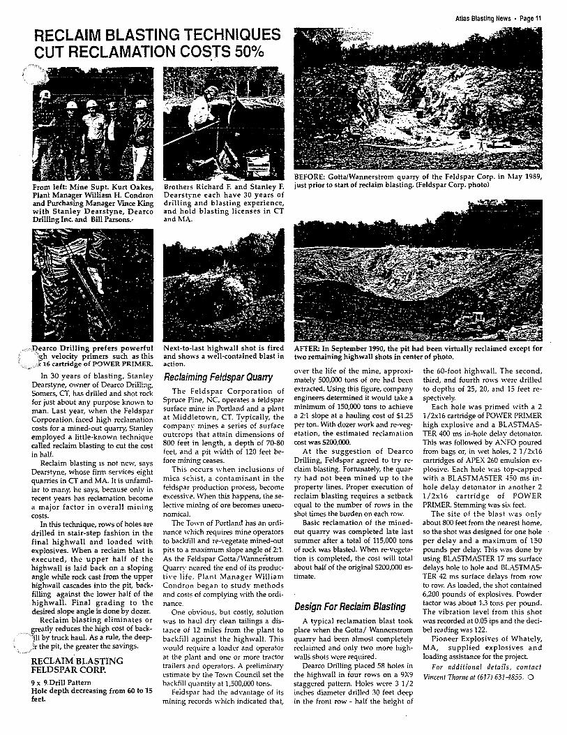
RECLAIM BLASTING TECHNIQUES CUT RECLAMATION COS.TS 50°/o
From left: Mine Supt. Kurt Oakes, Plant Manager William H. Condron and Purchasing Manager Vince King with Stanley Dearstyne, Dearco Drilling Inc. and Bill Parsons.·
1:?earco Drilling prefers powerful ih velocity primers such as this . < 16 cartridge of POWER PRIMER.
In 30 years of blasting, Stanley Dearstyne, owner of Dearco Drilling, Somers, CT, has drilled and shot rock .for just about any purpose known to man. Last year, when the Feldspar Corporation. faced high reclamation costs for a mined-out quarry, Stanley employed a little-known technique called reclaim blasting to cut the cost in half.
Reclaim blasting 1s not new, says Dearstyne, whose firm services eight quarries in CT and MA. It is unfamiliar to many, he says, because only in recent years has reclamation become a major factor in overall mining costs.
In this technique, rows of holes are drilled in stair-step fashion in the final highwall and loaded with explosives. When a reclaim blast is executed, the upper half of the highwall is laid back on a sloping angle while rock cast from the upper highwall cascades into the pit, backfilling against the lower half of the highwall. Final grading to the desired slope angle is done by dozer.
Reclaim blasting eliminates or greatly reduces the high cost of back'j.11 by truck haul. As a rule, the deep}r the pit, the greater the savings.
RECLAIM BLASTING FELDSPAR CORP.
9 x 9 Drill Pattern Hole depth decreasing from 60 to 15 feet.
Brothers Richard F. and Stanley F. Dearstyne each have 30 years of drilling and blasting experience, and hold blasting licenses in CT and MA.
Next-to-last highwall shot is fired and shows a well-contained blast in action.
Reclaiming Feldspar Quarry The Feldspar Corporation of
Spruce Pine, NC, operates a feldspar surface mine in Portland and a plant at Middletown, CT. Typically, the company mines a series of surface outcrops that attain dimensions of 800 feet in length, a depth of 70-80 feet, and a pit width of 120 feet before mining ceases.
This occurs when inclusions of mica schist, a contaminant in the feldspar production process, become excessh·e. When this happens, theselecth·e mining of ore becomes uneconomical.
The Town of Portland has an ordinance which requires mine operators to backfill and re-vegetate mined-out pits to a maximum slope angle of 2:1. As the Feldspar Gotta/Wannerstrom Quarry neared the end of its producti\·e life. Plant Manager William Condron began to study methods and costs of complying with the ordinance.
One obvious, but costly, solution was to haul dry clean tailings a distance oi 12 miles from the plant to backfill against the highwall. This would require a loader and operator at the plant and one or more tractor trailers and operators. A preliminary estimate bv the To.wn Council set the backfill qu.antity at 1,500,000 tons.
Feldspar had the advantage of its mining records which indicated that,
Atlas Blasting News • Page 11
BEFORE: Gotta/Wannerstrom quarry of the Feldspar Corp. in May 1989, just prior to start of reclaim blasting. (Feldspar Corp. photo)
AFTER: In September 1990, the pit had been virtually reclaimed except for two remaining highwall shots in center of photo .
over the life of the mine, approximately 500,000 tons of ore had been extracted. Using this figure, company engineers determined it would take a minimum of 150,000 tons to achieve a 2:1 slope at a hauling cost of $1.25 per ton. With dozer work and re-vegeta tion, the estimated reclamation cost was S200,000.
At the suggestion of Dearco Drilling, Feldspar agreed to try reclaim blasting. Fortunately, the quarry had not been mined up to the property lines. Proper execution of reclaim blasting requires a setback equal to the number of rows in the shot times the burden on each row.
Basic reclamation of the minedout quarry was completed late last summer after a total of 115,000 tons of rock was blasted. When re-vegetation is completed, the cost will total about half of the original $200,000 estimate.
Design For Reclaim Blasting A typical reclamation blast took
place when the Gotta/ Wannerstrom quarry had been almost completely reclaimed and only two more highwalls shots were required.
Dearco Drilling placed 58 holes in the highwall in four rows on a 9X9 staggered pattern. Holes were 3 1 /2 inches diameter drilled 30 feet deep in the front row - half the height of
the 60-foot highwall. The second, third, and fourth rows were drilled to depths of 25, 20, and 15 feet respectively.
Each hole was primed with a 2 1 /2x16 cartridge of POWER PRIMER high explosive and a BLASTMASTER 400 ms in-hole delay detonator. This was followed by ANFO poured from bags or, in wet holes, 2 1 /2x16 cartridges of APEX 260 emulsion explosive. Each hole was top-capped with a BLASTMASTER -150 ms inhole delav detonator in another 2 1 /2x16 'cartridge of POWER PRIMER. Stemming was six feet.
The site of the blast was onlv about 800 feet from the nearest horn;, so the shot was designed for one hole per delay and a maximum of 150 pounds per delay. This was done by using BLASTMASTER 17 ms surface delays hole to hole and BLASTMASTER 42 ms surface delays from row to row. As loaded, the shot contained 6,200 pounds of explosives. Powder factor was about l.3 tons per pound. The vibration level from this shot was recorded at 0.05 ips and the decibel reading was 122.
Pioneer Explosives of Whately, MA, supplied explosives and loading assistance for the project.
For additional details, contact Vincent Thorne al (617) 631-4855. 0
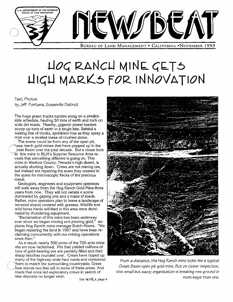
BUREAU OF LAND MANAGEMENT• CALIFORNIA •NOVEMBER 1993
Lloc; RANcLI tv11Nb. (;'b.Tb LI 1<:;LI tv1ARK:'..b f OR INNOVATION
Text, Photos by Jeff Fontana, Susanville District
The huge green trucks rumble along on a predictable schedule, hauling 50 tons of earth and rock on wide dirt roads. Nearby, gigantic power loaders scoop up tons of earth in a single bite. Behind a waiting line of trucks, sprinklers hiss as they spray a mist over a leveled mesa of crushed stone.
The scene could be from any of the open pit, \eap leach gold mines that have popped up in the Jreat Basin over the past decade. But a closer look
"at this mine in BL.M's Surprise Resource Area reveals that something different is going on. This mine in Washoe County, Nevada's high desert, is actually shutting down. Crews are not mining ore, but instead are repairing the scars they created in the quest for microscopic flecks of the precious metal.
Geologists, engineers and equipment operators will walk away from the Hog Ranch Gold Mine three years from now. They will not vacate a scene dominated by gaping pits and a maze of roads. Rather, mine operators plan to leave a landscape of terraced slopes covered with grasses. Wildlife and wild horse herds will feed in this area once dominated by thundering equipment.
"Reclamation of this mine has been underway ever since we began mining and pouring gold," explains Hog Ranch mine manager Butch Moore. "We began repairing the land in 1987 and have been reclaiming concurrently with our mining operations since then."
As a result, nearly 500 acres of the 720-acre mine site are now reclaimed. Pits that yielded millions of tons of gold-bearing ore are partially filled and their sharp benches rounded over. Crews have ripped up many of the highway-wide haul roads and contoured them to match the surrounding countryside. Grass
.how stands two feet tall in some of these areas. And roads that once led exploratory crews in search of new deposits no longer exist.
See ~INb.:, page4
From a distance, the Hog Ranch mine looks like a typical
Great Basin open pit gold mine. But on closer inspection, this small but sa\.1\-Y organization is breaking new ground in
more ways than one.
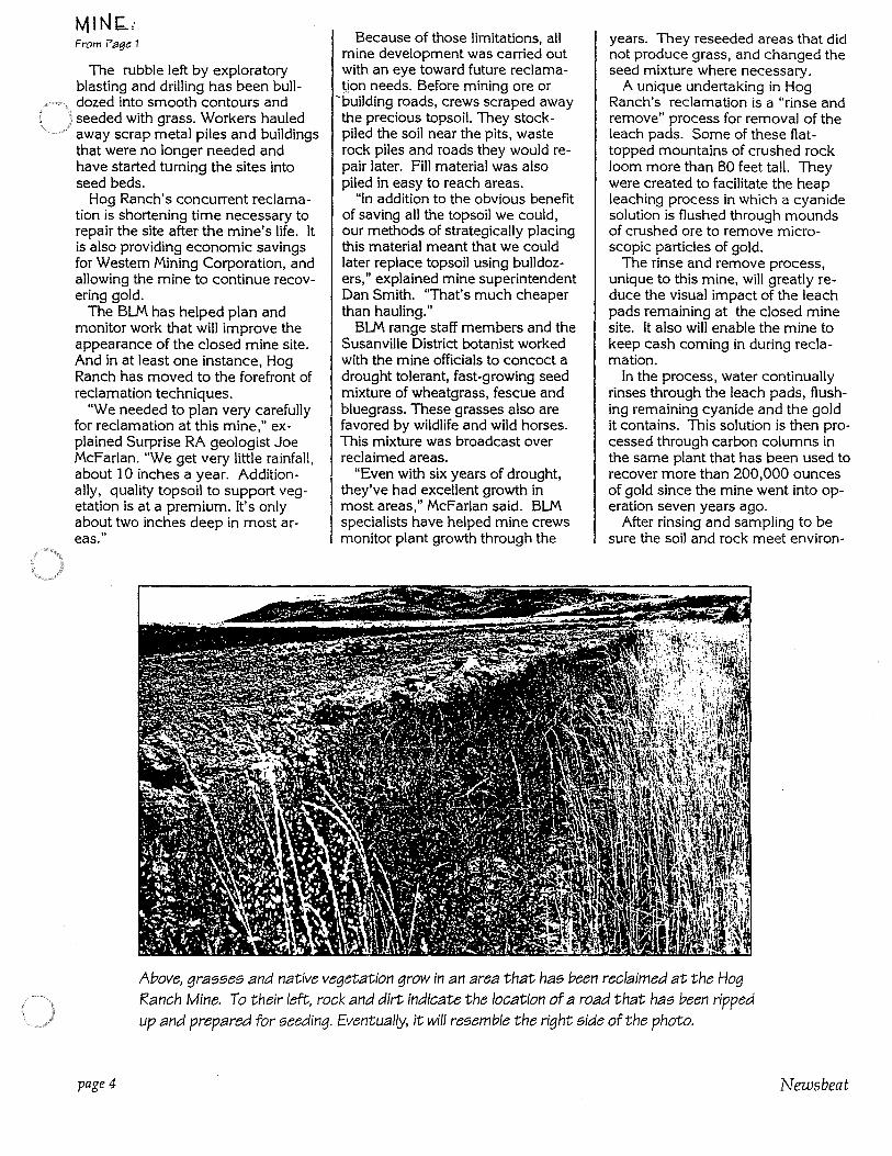
From Pag~ 1
The rubble left by exploratory blasting and drilling has been bulldozed into smooth contours and seeded with grass. Workers hauled away scrap metal piles and buildings that were no longer needed and have started turning the sites into seed beds.
Hog Ranch's concurrent reclamation is shortening time necessary to repair the site after the mine's life. It is also providing economic savings for Western Mining Corporation, and allowing the mine to continue recovering gold.
The BLM has helped plan and monitor work that will improve the appearance of the closed mine site. And in at least one instance, Hog Ranch has moved to the forefront of reclamation techniques.
"We needed to plan very carefully for reclamation at this mine," explained Surprise RA geologist Joe McFarlan. "We get very little rainfall, about 10 inches a year. Additionally, quality topsoil to support vegetation is at a premium. It's only about two inches deep in most areas."
Because of those limitations, all mine development was carried out with an eye toward future reclamatjon needs. Before mining ore or
'building roads, crews scraped away the precious topsoil. They stockpiled the soil near the pits, waste rock piles and roads they would repair later. Fill material was also piled in easy to reach areas.
"In addition to the obvious benefit of saving all the topsoil we could, our methods of strategically placing this material meant that we could later replace topsoil using bulldozers," explained mine superintendent Dan Smith. "That's much cheaper than hauling."
BLM range staff members and the Susanville District botanist worked with the mine officials to concoct a drought tolerant, fast-growing seed mixture of wheatgrass, fescue and bluegrass. These grasses also are favored by wildlife and wild horses. This mixture was broadcast over reclaimed areas.
"Even with six years of drought, they've had excellent growth in most areas," McFarlan said. BLM specialists have helped mine crews monitor plant growth through the
years. They reseeded areas that did not produce grass, and changed the seed mixture where necessary.
A unique undertaking in Hog Ranch's reclamation is a "rinse and remove" process for removal of the leach pads. Some of these flattopped mountains of crushed rock loom more than 80 feet tall. They were created to facilitate the heap leaching process in which a cyanide solution is flushed through mounds of crushed ore to remove microscopic particles of gold.
The rinse and remove process, unique to this mine, will greatly reduce the visual impact of the leach pads remaining at the closed mine site. It also will enable the mine to keep cash coming in during reclamation.
In the process, water continually rinses through the leach pads, flushing remaining cyanide and the gold it contains. This solution is then processed through carbon columns in the same plant that has been used to recover more than 200,000 ounces of gold since the mine went into operation seven years ago.
After rinsing and sampling to be sure the soil and rock meet environ-
Above, grasses and native vegetation grow in an area that has been reclaimed at the Hog Ranch Mine. To their left, rock and dirt indicate the location of a road that has been ripped up and prepared for seeding. Eventually, it will resemble the right side of the photo.
page4 Newsbeat
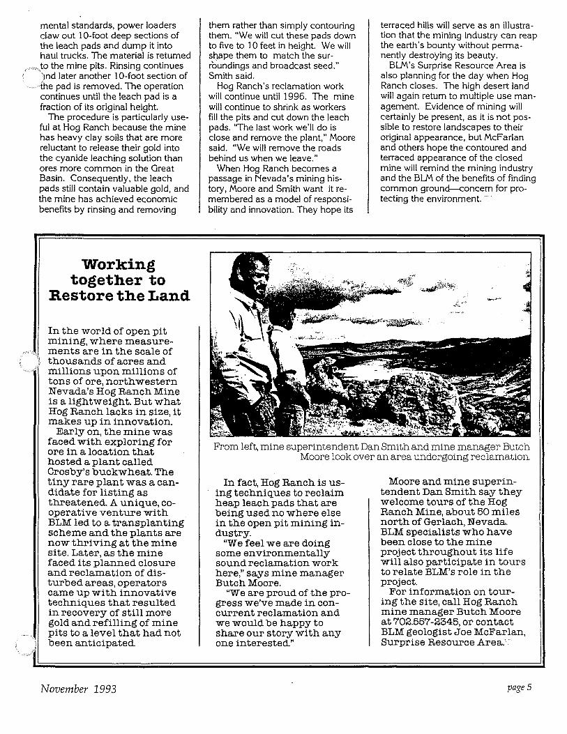
mental standards, power loaders claw out 10-foot deep sections of the leach pads and dump it into haul trucks. The material is returned
.. to the mine pits. Rinsing continues )nd later another 10-foot section of the pad is removed. The operation continues until the leach pad is a fraction of its original height.
The procedure is particularly useful at Hog Ranch because the mine has heavy clay soils that are more reluctant to release their gold into the cyanide leaching solution than ores more common in the Great Basin. Consequently, the leach pads still contain valuable gold, and the mine has achieved economic benefits by rinsing and removing
Working together to
Restore the Land
In the world of open pit mining, where measurements are in the scale of thousands of acres and millions upon millions of tons of ore, northwestern Nevada's Hog Ranch Mine is a lightweight. But what Hog Ranch lacks in size, it makes up in innovation.
Early on, the mine was faced with exploring for ore in a location that hosted a plant called Crosby's buckwheat. The tiny rare plant was a candidate for listing as threatened A unique, cooperative venture with BLM led to a transplanting scheme and the plants are now thriving at the mine site. Later, as the mine faced its planned closure and reclamation of disturbed areas, operators came up with innovative techniques that resulted in recovery of still more gold and refilling of mine pits to a level that had not been anticipated
November 1993
them rather than simply contouring them. "We will cut these pads down to five to 10 feet in height. We will sri.ape them to match the surroundings and broadcast seed," Smith said.
Hog Ranch's reclamation work will continue until 1996. The mine will continue to shrink as workers fill the pits and cut down the leach pads. "The last work we'll do is close and remove the plant," Moore said. "We will remove the roads behind us when we leave."
When Hog Ranch becomes a passage in Nevada's mining history, Moore and Smith want it remembered as a model of responsibility and innovation. They hope its
terraced hills will serve as an illustration that the mining industry can reap the earth's bounty without permanently destroying its beauty.
BL.M's Surprise Resource Area is also planning for the day when Hog Ranch closes. The high desert land will again return to multiple use management. Evidence of mining will certainly be present, as it is not possible to restore landscapes to their original appearance, but McFarlan and others hope the contoured and terraced appearance of the closed mine will remind the mining industry and the BL.M of the benefits of finding common ground-<:oncern for protecting the environment. ·-:··
From left, mine superintendent Dan Smith and mine manager Butch Moore look over an area undergoing reclamation.
In fact, Hog Ranch is using techniques to reclaim heap leach pads that are being used no where else in the open pit mining industry.
"We feel we are doing some environmentally sound reclamation work here," says mine manager Butch Moore.
"We are proud of the progress we've made in concurrent reclamation and we would be happy to share our story with any one interested"
Moore and mine superintendent Dan Smith say they welcome tours of the Hog Ranch Mine, about 50 miles north of Gerlach, Nevada. BLM specialists who have been close to the mine project throughout its life will also participate in tours to relate BLM's role in the project.
For information on touring the site, call Hog Ranch mine manager Butch Moore at 702.557-2345, or contact BLM geologist Joe McFarlan, Surprise Resource Area: ··
pages
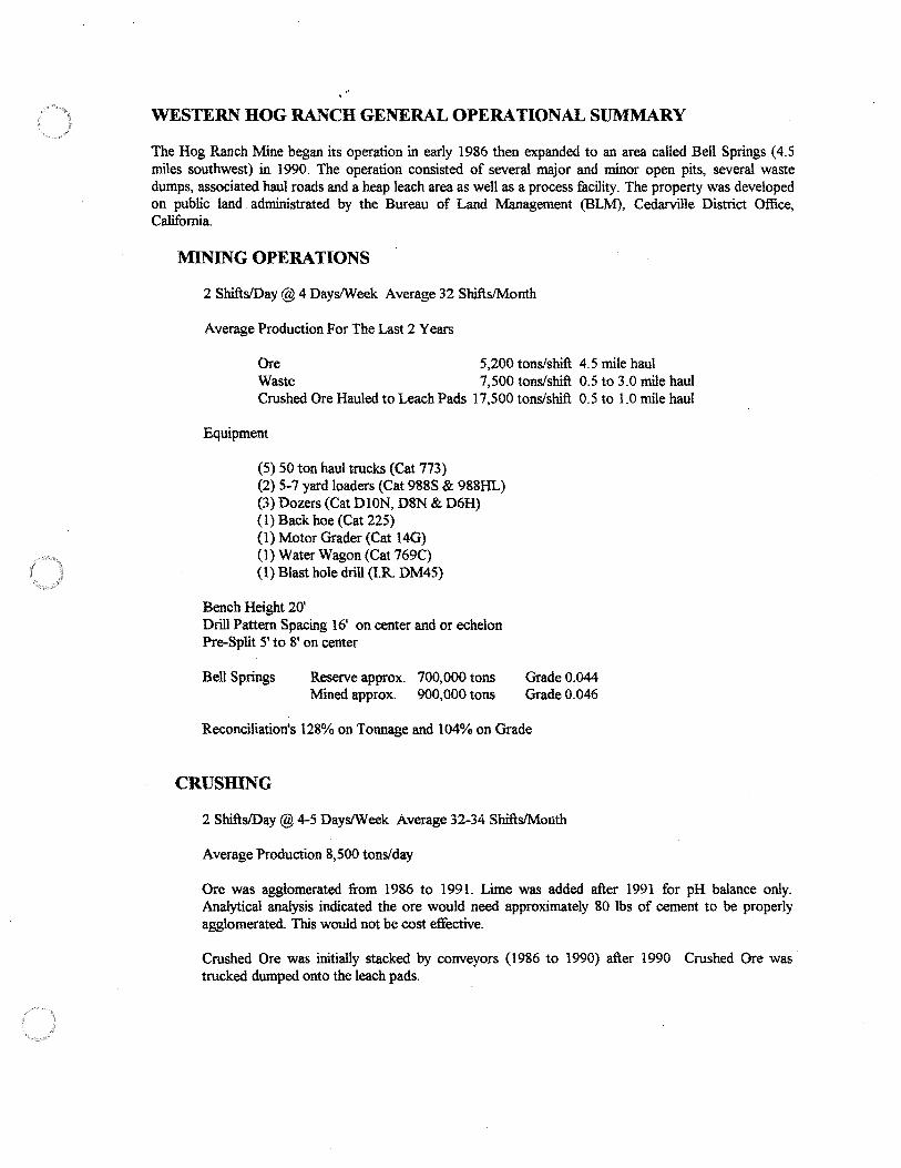
WESTERN HOG RANCH GENERAL OPERATIONAL SUMMARY
The Hog Ranch Mine began its operation in early 1986 then expanded to an area called Bell Springs (4.5 miles southwest) in 1990. The operation consisted of several major and minor open pits, several waste dumps, associated haul roads and a heap leach area as well as a process facility. The property was developed on public land administrated by the Bureau of Land Management (BLM), Cedarville District Office, California.
MINING OPERATIONS
2 Shifts/Day@4 Days/Week Average 32 Shifts/Month
Average Production For The Last 2 Years
Ore 5,200 tons/shift 4.5 mile haul Waste 7,500 tons/shift 0.5 to 3.0 mile haul Crushed Ore Hauled to Leach Pads 17,500 tons/shift 0.5 to 1.0 mile haul
Equipment
(5) 50 ton haul trucks (Cat 773) (2) 5-7 yard loaders (Cat 988S & 988HL) (3) Dozers (Cat DION, D8N & D6H) (1) Back hoe (Cat 225) (1) Motor Grader (Cat 14G) (1) Water Wagon (Cat 769C) (I) Blast hole drill (I.R. DM45)
Bench Height 20' Drill Pattern Spacing 16' on center and or echelon Pre-Split 5' to 8' on center
Bell Springs Reserve approx. 700,000 tons Mined approx. 900,000 tons
Grade0.044 Grade0.046
Reconciliation's 128% on Tonnage and 104% on Grade
CRUSHING
2 Shifts/Day@4-5 Days/Week Average 32-34 Shifts/Month
Average Production 8,500 tons/day
Ore was agglomerated from 1986 to 1991. Lime was added after 1991 for pH balance only. Analytical analysis indicated the ore would need approximately 80 lbs of cement to be properly agglomerated. This would not be cost effective.
Crushed Ore was initially stacked by conveyors (1986 to 1990) after 1990 Crushed Ore was trucked dumped onto the leach pads.
RECLAMATION
Reclamation was concurrent with operations from 1987 to the present. To date the only reclamation remaining are the leach pads, process facilities, and office/shop areas. Reclamation practices far exceed the operational permit. Examples:
Pit high walls have been drilled and shot then re-contoured and seeded. Pit high walls have been re-contoured and seeded. Pits have been back-filled and re-contoured and seeded. Waste dumps have been re-contoured to 3: I slopes rather than angle of repose
The reclamation seed mixture was developed for a drought resistant environment and to survive for only a few years until the natives can take over. Reclamation has been very successful as to date. The BLM has recognized and sign off 500 reclaimed acres out of a disturbance of approximately 700 acres.
Reclamation costs average approximately $550/acre.
LEACH PADS
To date approximately 60% of the Cyanide Soluble gold has been recovered.
The mine is now in the process of rinsing the spent ore to state standards (on a 10' lift). The rinsed residue is then off-loaded and back-filled into one of the existing pits. This process will push out any cyanide soluble gold while rinsing the leach pads to meet state standards.
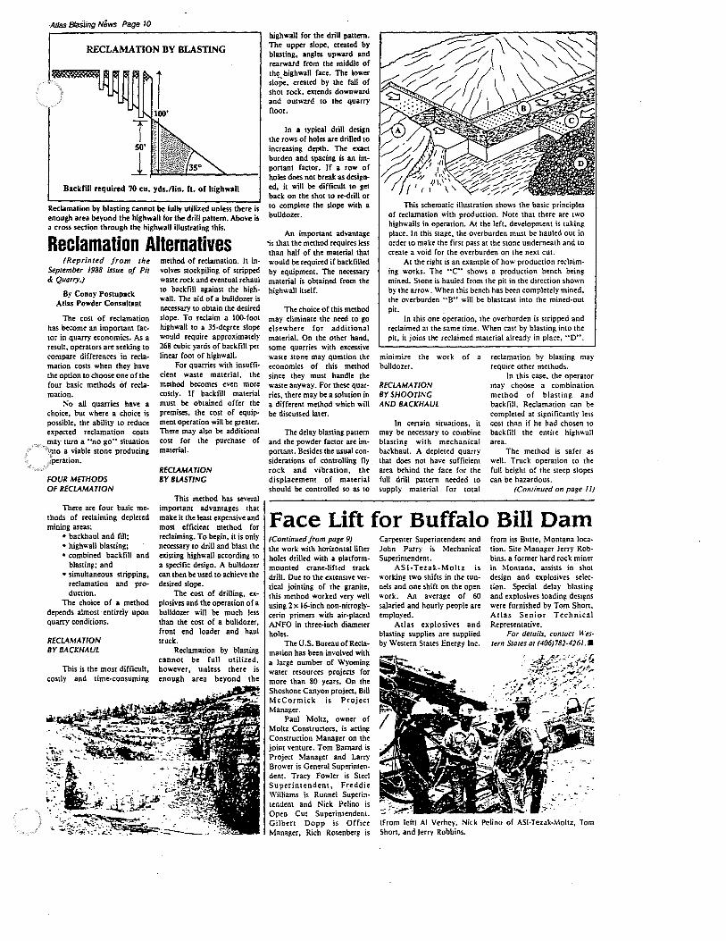
AJJa.s Blasting News Page 10
RECLAMATION BY BLASTING
Backfill required 70 cu. yds./lin. ft. of highwall
Reclamation by blasting cannot be fully utilized unless there is enough area beyond the highwall for the drill pattern. Above is a cross section through the highwall illustrating this.
Reclamation Alternatives (Reprinted from the
September 1988 issue of Pit & Quarry.)
By Conny Postupack Atlas Powder Consultant
The cost of reclamation has become an important factor in quarry economics. As a result, operators are seeking to compare differences in reclamation costs when they have the option to choose one of the four basic methods of reclamation.
!','o all quarries have a choice, but where a choice is possible, the ability to reduce expected reclamation costs may turn a "no go0 situation
\,110 a viable stone producing )?peration.
FOUR METHODS OF RECLAMATION
There are four basic methods of reclaiming depleted mining areas:
• backhaul and fill; • highwall blasting; • combined backfill and
blasting; and • simultaneous stripping,
reclamation and production.
The choice of a method depends almost ·entirely upon quarry conditions.
RECLAMATION BY BACKHAUL
This is the most difficult, costly and time-consuming
method of reclamation. It involves stockpiling of stripped waste rock and eventual rehaul to backfill against the higliwall. The aid of a bulldozer is necessary to obtain the desired slope. To reclaim a 100-foot highwall to a 35-degree slope would require approximately 268 cubic yards of backfill per linear foot of highwall.
For quarries with insufficient waste material, the method becomes even more costly. If backfill material must be obtained offer the premises, the cost of equipment operation will be greater. There may also be additional cost for the purchase of material.
RECLAMATION BY BLASTING
This method has several important advantages that make it the least expensive and most efficient method for reclaiming. To begin, it is only necessary to drill and blast the existing highwall according to a specific design. A bulldozer can then be used to achieve the desired slope.
The cost of drilling, explosives and the operation of a bulldozer will be much less than the cost of a bulldozer, front end loader and haul truck.
Reclamation by blasting cannot be full utilized, however, unless there is enough area beyond the
highwall for the drill pattern. The upper slope, created by blasting, angles upward and rearward from the middle of the highwall face. The lower slope, created by the fall of shot rock. extends downward and outward to the quarry floor.
In a typical drill design the rows of holes arc drilled to increasing depth. The exact burden and spacing is an important factor. If a row of holes does not break as designed, it will be difficult to get back on the shot to re-drill or to complete the slope with a bulldozer.
An important advantage 'is that the method requires less than half of the material that would be required if backfilled by equipment. The necessary material is obtained from the highwall itself.
The choice of this method may eliminate the need to go elsewhere for additional material. On the other hand, some quarries with excessive waste stone may question the economics of this method since they must handle the waste anyway. For these quarries, there may be a solution in a different method which will be discussed later.
The delay blasting pattern and the powder factor are important. Besides the usual considerations of controlling fly. rock and vibration, the displacement of material should be controlled so as to
This schematic illustration shows the basic principles of reclamation with production. Note that there are 1wo highwalls in operation. At the left, development is taking place. In this stage, the overburden must be hauled out in order to make the first pass at the stone underneath and to create a void for the overburden on the next cut.
At the right is an example of how production reclaiming works. The "C" shows a production bench being mined. Stone is hauled from the pit in the direction shown by the arrow. When this bench has been completely mined, the overburden "B" will be blastcasl into the mined-out pit.
In this one ~peration, the overburden is stripped and reclaimed at the same time. When cast by blasting into the pit, it joins the reclaimed material already in place, "D".
minimize the work of a bulldozer.
RECLAMATION BY SHOOTING AND BACKHAUL
ln cenain situations, it may be necessary to combine blasting with mechanical backhaul. A depleted quarry that does not have sufficient area behind the face for the full drill pattern needed to supply material for total
reclamation by blasting may require other methods.
In this case, the operator may choose a combination method of blasting and backfill. Reclamation can be completed at significantly less cost than if he had chosen to backfill the entire highwall area.
The method is safer as well. Truck operation to the full height of the steep slopes can be hazardous.
(Continued on page Iii
Face Lift for Buffalo Bill Dam (Continued from poge 9) the work with horizontai lifter holes drilled with a platformmounted crane-lift<d track drill. Due to the extensive ver· tical jointing of the granite, this method worked very well using 2x 16-inch non-nitroglycerin primers with air-placed ANFO in three-inch diameter holes.
The U.S. Bureau of Reclamation has been involved with a large number of Wyoming water resources projects for more than 80 years. On the Shoshone Canyon project, Bill McCormick is Project Manager.
Paul Moltz, owner of Moltz Constructors, is acting Construction Manager on the joint venture. Tom Barnard is Project Manager and Larry Brower is General Superintendent. Tracy Fowler is Steel Superintendent, Freddie Williams is Runnel Superintendent and Nick Pelino is Open Cut Superintendent. Gilbert Dopp is Office Manager, Rich Rosenberg is
Carpenter Superintendent and John Parry is Mechanical Superintendent.
AS!-Tezak-Moltz is working two shifts in the tunnels and one shift on the open work. An average of 60 salaried and hourly people are employed.
Atlas explosives and blasting supplies arc supplied by Western States Energy Inc.
from its Butte, Montana loca· tion. Site Manager Jerry Robbins. a former hard rock miner in Montana, assists in shot design and explosi,·es selection. Special delay blasting and explosives loading designs were furnished by Tom Shon, Atlas Senior Technical Representative.
For derails, contacr Wesrern Slates at (406)782-426/. •
(From left) Al Verhey, Nick Pelino of ASI-Tezak-Moltz, Tom Short, and Jerry Robbins.