Embed Size (px)
Citation preview
1253
Chapter 29
1. (a) The magnitude of the magnetic field due to the current in the wire, at a point a
distance r from the wire, is given by
Bi
r0
2.
With r = 20 ft = 6.10 m, we have
B
4 100
233 10 336
T m A A
mT T.
c hb gb g . .
(b) This is about one-sixth the magnitude of the Earth’s field. It will affect the compass
reading.
2. Equation 29-1 is maximized (with respect to angle) by setting = 90º ( = /2 rad). Its
value in this case is
0max 24
i dsdB
R
.
From Fig. 29-35(b), we have 12
max 60 10 T.B We can relate this Bmax to our dBmax by
setting “ds” equal to 1 106
m and R = 0.025 m. This allows us to solve for the current:
i = 0.375 A. Plugging this into Eq. 29-4 (for the infinite wire) gives B = 3.0 T.
3. THINK The magnetic field produced by a current-carrying wire can be calculated
using the Biot-Savart law.
EXPRESS The magnitude of the magnetic field at a distance r from a long straight wire
carrying current i is, using the Biot-Savart law, 0 2 .B i r
ANALYZE (a) The field due to the wire, at a point 8.0 cm from the wire, must be 39 T
and must be directed due south. Therefore,
irB
2 2 39 10
416
0
6
m T
T m AA.
b gc h
(b) The current must be from west to east to produce a field that is directed southward at
points below it.
LEARN The direction of the current is given by the right-hand rule: grasp the element in
your right hand with your thumb pointing in the direction of the current. The direction of
CHAPTER 29 1254
the field due to the current-carrying element corresponds to the direction your fingers
naturally curl.
4. The straight segment of the wire produces no magnetic field at C (see the straight
sections discussion in Sample Problem 29.01 — “Magnetic field at the center of a
circular arc of current”). Also, the fields from the two semicircular loops cancel at C (by
symmetry). Therefore, BC = 0.
5. (a) We find the field by superposing the results of two semi-infinite wires (Eq. 29-7)
and a semicircular arc (Eq. 29-9 with = rad). The direction of B is out of the page, as
can be checked by referring to Fig. 29-7(c). The magnitude of B at point a is therefore
7
30 0 0 1 1 (4 10 T m/A)(10 A) 1 12 1.0 10 T
4 2 2 2(0.0050 m) 2a
i i iB
R R R
upon substituting i = 10 A and R = 0.0050 m.
(b) The direction of this field is out of the page, as Fig. 29-7(c) makes clear.
(c) The last remark in the problem statement implies that treating b as a point midway
between two infinite wires is a good approximation. Thus, using Eq. 29-4,
7
40 0 (4 10 T m/A)(10 A)2 8.0 10 T.
2 (0.0050 m)b
i iB
R R
(d) This field, too, points out of the page.
6. With the “usual” x and y coordinates used in Fig. 29-38, then the vector r
pointing
from a current element to P is ˆ ˆi j .r s R Since ids ds , then | | .ds r Rds
Therefore, with 2 2r s R , Eq. 29-3 gives
0
2 2 3/ 24 ( )
iR dsdB
s R
.
(a) Clearly, considered as a function of s (but thinking of “ds” as some finite-sized
constant value), the above expression is maximum for s = 0. Its value in this case is 2
max 0 / 4dB i ds R .
(b) We want to find the s value such that max /10dB dB . This is a nontrivial algebra
exercise, but is nonetheless straightforward. The result is s = 102/3
1 R. If we set
2.00 cm,R then we obtain s = 3.82 cm.
1255
7. (a) Recalling the straight sections discussion in Sample Problem 29.01 — “Magnetic
field at the center of a circular arc of current,” we see that the current in the straight
segments collinear with P do not contribute to the field at that point. Using Eq. 29-9 (with
= ) and the right-hand rule, we find that the current in the semicircular arc of radius b
contributes 0 4i b (out of the page) to the field at P. Also, the current in the large
radius arc contributes 0 4i a (into the page) to the field there. Thus, the net field at P
is
0 1 1 (4 T m A)(0.411A)(74 /180 ) 1 1
4 4 0.107m 0.135m
1.02 T.
iB
b a
-7
-7
p 10
10
(b) The direction is out of the page.
8. (a) Recalling the straight sections discussion in Sample Problem 29.01 — “Magnetic
field at the center of a circular arc of current,” we see that the current in segments AH and
JD do not contribute to the field at point C. Using Eq. 29-9 (with = ) and the right-
hand rule, we find that the current in the semicircular arc H J contributes 0 14i R (into
the page) to the field at C. Also, arc D A contributes 0 24i R (out of the page) to the
field there. Thus, the net field at C is
0
1 2
1 1 (4 T m A)(0.281A) 1 11.67 T.
4 4 0.0315m 0.0780m
iB
R R
-7-6p 10
10
(b) The direction of the field is into the page.
9. THINK The net magnetic field at a point half way between the two long straight wires
is the vector sum of the magnetic fields due to the currents in the two wires.
EXPRESS Since the magnitude of the magnetic field at a distance r from a long straight
wire carrying current i is given by 0 2 ,B i r at a point half way between the two sires,
the magnetic field is 1 2 ,B B B where 1 2 0 2B B i r (assuming the two wires to
be 2r apart). The directions of 1B and 2B are determined by the right-hand rule.
ANALYZE (a) The currents must be opposite or anti-parallel, so that the resulting fields
are in the same direction in the region between the wires. If the currents are parallel, then
the two fields are in opposite directions in the region between the wires. Since the
currents are the same, the total field is zero along the line that runs halfway between the
wires.
(b) The total field at the midpoint has magnitude B = 0i/r and
CHAPTER 29 1256
6m 300 10 T30A.
4 T m A
rBi
-7
0
p 0.040p
p 10
LEARN For two parallel wires carrying currents in the opposite directions, a point that is
a distance d from one wire and 2r – d from the other, the magnitude of the magnetic field
is
0 0 01 2
1 1
2 2 (2 ) 2 2
i i iB B B
d r d d r d
.
10. (a) Recalling the straight sections discussion in Sample Problem 29.01 — “Magnetic
field at the center of a circular arc of current,” we see that the current in the straight
segments collinear with C do not contribute to the field at that point.
Equation 29-9 (with = ) indicates that the current in the semicircular arc contributes
0 4i R to the field at C. Thus, the magnitude of the magnetic field is
0 (4 T m A)(0.0348A)1.18 T.
4 4(0.0926m)
iB
R
-7-7p 10
10
(b) The right-hand rule shows that this field is into the page.
11. (a) 1 0 1 1/ 2PB i r where i1 = 6.5 A and r1 = d1 + d2 = 0.75 cm + 1.5 cm = 2.25 cm,
and 2 0 2 2/ 2PB i r where r2 = d2 = 1.5 cm. From BP1 = BP2 we get
22 1
1
1.5 cm6.5A 4.3A.
2.25 cm
ri i
r
(b) Using the right-hand rule, we see that the current i2 carried by wire 2 must be out of
the page.
12. (a) Since they carry current in the same direction, then (by the right-hand rule) the
only region in which their fields might cancel is between them. Thus, if the point at
which we are evaluating their field is r away from the wire carrying current i and is d – r
away from the wire carrying current 3.00i, then the canceling of their fields leads to
0 0 (3 ) 16.0 cm 4.0 cm.
2 2 ( ) 4 4
i i dr
r d r
(b) Doubling the currents does not change the location where the magnetic field is zero.
13. Our x axis is along the wire with the origin at the midpoint. The current flows in the
positive x direction. All segments of the wire produce magnetic fields at P1 that are out of
1257
the page. According to the Biot-Savart law, the magnitude of the field any (infinitesimal)
segment produces at P1 is given by
dBi
rdx
0
24sin
where (the angle between the segment and a line drawn from the segment to P1) and r
(the length of that line) are functions of x. Replacing r with x R2 2 and sin with
R r R x R 2 2 , we integrate from x = –L/2 to x = L/2. The total field is
2 20 0 0
3 2 1 22 2 22 2 2 2 2 2
8
2 2
1
4 4 2 4
4 T m A 0.0582 A 0.180m5.03 10 T.
m (0.180m) 4(0.131m)
L L
L L
iR iR idx x LB
R R L Rx R x R
-7
p p p
p 10
2p 0.131
14. We consider Eq. 29-6 but with a finite upper limit (L/2 instead of ). This leads to
0
2 2
/ 2
2 ( / 2)
i LB
R L R
.
In terms of this expression, the problem asks us to see how large L must be (compared
with R) such that the infinite wire expression B (Eq. 29-4) can be used with no more
than a 1% error. Thus we must solve
B – B
B = 0.01.
This is a nontrivial algebra exercise, but is nonetheless straightforward. The result is
20014.1 14.1
201
R LL R
R .
15. (a) As discussed in Sample Problem 29.01 — “Magnetic field at the center of a
circular arc of current,” the radial segments do not contribute to BP and the arc segments
contribute according to Eq. 29-9 (with angle in radians). If k designates the direction
“out of the page” then
0 0 6
0.40A rad 0.80A 2 / 3radˆ ˆ ˆk k (1.7 10 T)k4 0.050m 4 0.040m
B
or 6| | 1.7 10 TB .
(b) The direction is k , or into the page.
CHAPTER 29 1258
(c) If the direction of i1 is reversed, we then have
0 0 6
0.40A rad 0.80A 2 / 3radˆ ˆ ˆk k (6.7 10 T)k4 0.050m 4 0.040m
B
or 6| | 6.7 10 T.B
(d) The direction is k , or into the page.
16. Using the law of cosines and the requirement that B = 100 nT, we have
2 2 2
1 1 2
1 2
cos 1442
B B B
B B
,
where Eq. 29-10 has been used to determine B1 (168 nT) and B2 (151 nT).
17. THINK We apply the Biot-Savart law to calculate the magnetic field at point P2. An
integral is required since the length of the wire is finite.
EXPRESS We take the x axis to be along the wire with the origin at the right endpoint.
The current is in the +x direction. All segments of the wire produce magnetic fields at P2
that are out of the page. According to the Biot-Savart law, the magnitude of the field any
(infinitesimal) segment produces at P2 is given by
dBi
rdx
0
24sin
where (the angle between the segment and a line drawn from the segment to P2) and r
(the length of that line) are functions of x. Replacing r with x R2 2 and sin with
R r R x R 2 2 , we integrate from x = –L to x = 0.
ANALYZE The total field is
0 00 0
3 2 1 22 2 22 2 2 2
7
2 2
1
4 4 4
4 T m A 0.693 A 0.136 m1.32 10 T.
m (0.136 m) (0.251 m)
L L
iR iR idx x LB
R R L Rx R x R
LEARN In calculating B at P2, we could have chosen the origin to be at the left endpoint.
This only changes the integration limit, but the result remains the same:
1259
0 0
3 2 1 22 2 20 2 2 2 2 0
1
4 4 4
L LiR iR idx x LB
R R L Rx R x R
.
18. In the one case we have Bsmall + Bbig = 47.25 T, and the other case gives Bsmall – Bbig
= 15.75 T (cautionary note about our notation: Bsmall refers to the field at the center of
the small-radius arc, which is actually a bigger field than Bbig!). Dividing one of these
equations by the other and canceling out common factors (see Eq. 29-9) we obtain
small big small big
small big small big
(1/ ) (1/ ) 1 ( / )3
(1/ ) (1/ ) 1 ( / )
r r r r
r r r r
.
The solution of this is straightforward: rsmall = rbig /2. Using the given fact that the
big 4.00 cm,r then we conclude that the small radius is small 2.00 cm.r
19. The contribution to netB from the first wire is (using Eq. 29-4)
7
60 11
1
(4 10 T m/A)(30 A)ˆ ˆ ˆk k (3.0 10 T)k.2 2 (2.0 m)
iB
r
The distance from the second wire to the point where we are evaluating netB is r2 = 4 m
2 m = 2 m. Thus, 7
60 22
2
(4 10 T m/A)(40 A)ˆ ˆ ˆi i (4.0 10 T)i.2 2 (2.0 m)
iB
r
and consequently is perpendicular to 1B . The magnitude of netB is therefore
6 2 6 2 6
net| | (3.0 10 T) (4.0 10 T) 5.0 10 TB .
20. (a) The contribution to BC from the (infinite) straight segment of the wire is
Bi
RC1
0
2
.
The contribution from the circular loop is Bi
RC2
0
2
. Thus,
3
701 2
4 T m A 5.78 10 A1 11 1 2.53 10 T.
2 2 mC C C
iB B B
R
CHAPTER 29 1260
BC points out of the page, or in the +z direction. In unit-vector notation,
7 ˆ(2.53 10 T)kCB
(b) Now, B BC C1 2 so
3
2 2 701 2
4 T m A 5.78 10 A1 11 1 2.02 10 T.
2 2 mC C C
iB B B
R
-7p 10
0.0189
and BC points at an angle (relative to the plane of the paper) equal to
1 11
2
1tan tan 17.66 .C
C
B
B
In unit-vector notation,
7 7 8ˆ ˆ ˆ ˆ2.02 10 T(cos17.66 i sin17.66 k) (1.92 10 T)i (6.12 10 T)kCB .
21. Using the right-hand rule (and symmetry), we see that B
net points along what we will
refer to as the y axis (passing through P), consisting of two equal magnetic field y-
components. Using Eq. 29-17,
0net| | 2 sin
2
iB
r
where i = 4.00 A, r = 2 2
2 1 / 4 5.00 m,r d d and
1 1 12
1
4.00 m 4tan tan tan 53.1
/ 2 6.00 m / 2 3
d
d
.
Therefore,
0net
(4 T m A)(4.00 A)| | sin sin53.1 2.56 T
( m)
iB
r
.
22. The fact that By = 0 at x = 10 cm implies the currents are in opposite directions. Thus,
0 1 0 2 0 2 4 1
2 ( ) 2 2y
i i iB
L x x L x x
using Eq. 29-4 and the fact that 1 24i i . To get the maximum, we take the derivative with
respect to x and set equal to zero. This leads to 3x2 – 2Lx – L
2 = 0, which factors and
becomes (3x + L)(x L) = 0, which has the physically acceptable solution: x = L . This
produces the maximum By: oi2/2L. To proceed further, we must determine L.
1261
Examination of the datum at x = 10 cm in Fig. 29-50(b) leads (using our expression
above for By and setting that to zero) to L = 30 cm.
(a) The maximum value of By occurs at x = L = 30 cm.
(b) With i2 = 0.003 A we find o i2 /2L = 2.0 nT.
(c) and (d) Figure 29-50(b) shows that as we get very close to wire 2 (where its field
strongly dominates over that of the more distant wire 1) By points along the –y direction.
The right-hand rule leads us to conclude that wire 2’s current is consequently is into the
page. We previously observed that the currents were in opposite directions, so wire 1’s
current is out of the page.
23. We assume the current flows in the +x direction and the particle is at some distance d
in the +y direction (away from the wire). Then, the magnetic field at the location of a
proton with charge q is 0ˆ( / 2 )k.B i d Thus,
F qv B
iq
dv
0
2 .ke j
In this situation, v v je j (where v is the speed and is a positive value), and q > 0. Thus,
19
0 0 (4 T m A)(0.350A)(1.60 10 C)(200m/s)ˆ ˆ ˆ ˆj k i i2 2 2 (0.0289 m)
ˆ( 7.75 N)i.
iqv iqvF
d d
-7
-23
p 10
p p
10
24. Initially, we have Bnet,y = 0 and Bnet,x = B2 + B4 = 2(o i /2d) using Eq. 29-4, where
0.15 md . To obtain the 30º condition described in the problem, we must have
0net, net, 1 3tan(30 ) 2 tan(30 )
2y x
iB B B B
d
where B3 = o i /2d and 1 0 / 2 .B i d Since tan(30º) = 1/ 3 , this leads to
3
0.4643 2
d d d
.
(a) With d = 15.0 cm, this gives d = 7.0 cm. Being very careful about the geometry of
the situation, then we conclude that we must move wire 1 to x = 7.0 cm.
(b) To restore the initial symmetry, we would have to move wire 3 to x = +7.0 cm.
CHAPTER 29 1262
25. THINK The magnetic field at the center of the circle is the vector sum of the fields of
the two straight wires and the arc.
EXPRESS Each of the semi-infinite straight wires contributes straight 0 4B i R (Eq.
29-7) to the field at the center of the circle (both contributions pointing “out of the page”).
The current in the arc contributes a term given by Eq. 29-9: 0arc
iB
R
, pointing into the
page.
ANALYZE The total magnetic field is
0 0 0straight arc2 2 2 .
4 4
i i iB B B
R R R
Therefore, = 2.00 rad would produce zero total field at the center of the circle.
LEARN The total contribution of the two semi-infinite wires is the same as that of an
infinite wire. Note that the angle is in radians rather than degrees.
26. Using the Pythagorean theorem, we have
2 2
2 2 2 0 1 0 21 2
2
i iB B B
R R
which, when thought of as the equation for a line in a B2
versus i22 graph, allows us to
identify the first term as the “y-intercept” (1 1010
) and the part of the second term that
multiplies i22 as the “slope” (5 10
10). The latter observation leads to
22
10 2 2 0 4 T m A5.00 10 T /A
2 2R R
or 2 2 2
2 2 3
10 2 2
4.00 T m A8.00 m 8.94 10 m 8.9 mm.
5.00 10 T /AR R
The other observation about the “y-intercept” determines the angle subtended by the arc:
22
10 2 2 11 2 20 1
3
(4 T m A)(0.50 A)1.00 10 T (3.13 10 ) T
4 4 (8.94 10 m)
i
R
or 10 2
2
11 2
1.00 10 T3.19 1.79 rad 1.8 rad.
3.13 10 T
1263
27. We use Eq. 29-4 to relate the magnitudes of the magnetic fields B1 and B2 to the
currents (i1 and i2, respectively) in the two long wires. The angle of their net field is
= tan1
(B2 /B1) = tan1
(i2 /i1) = 53.13º.
The accomplish the net field rotation described in the problem, we must achieve a final
angle = 53.13º – 20º = 33.13º. Thus, the final value for the current i1 must be i2 /tan = 61.3 mA.
28. Letting “out of the page” in Fig. 29-56(a) be the positive direction, the net field is
0 1 0 2
2 ( / 2)
i iB
R R
from Eqs. 29-9 and 29-4. Referring to Fig. 29-56, we see that B = 0 when i2 = 0.5 A, so
(solving the above expression with B set equal to zero) we must have
= 4(i2 /i1) = 4(0.5/2) = 1.00 rad (or 57.3º).
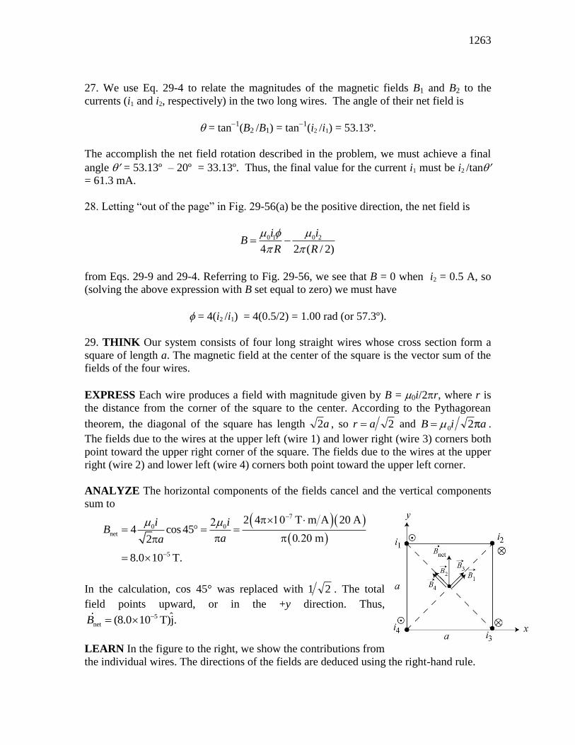
29. THINK Our system consists of four long straight wires whose cross section form a
square of length a. The magnetic field at the center of the square is the vector sum of the
fields of the four wires.
EXPRESS Each wire produces a field with magnitude given by B = 0i/2r, where r is
the distance from the corner of the square to the center. According to the Pythagorean
theorem, the diagonal of the square has length 2a , so r a 2 and B i a 0 2 .
The fields due to the wires at the upper left (wire 1) and lower right (wire 3) corners both
point toward the upper right corner of the square. The fields due to the wires at the upper
right (wire 2) and lower left (wire 4) corners both point toward the upper left corner.
ANALYZE The horizontal components of the fields cancel and the vertical components
sum to
0
net
5
2 4 T m A 20 A4 cos 45
m2
8.0 10 T.
i iB
aa
In the calculation, cos 45° was replaced with 1 2 . The total
field points upward, or in the +y direction. Thus, 5
netˆ(8.0 10 T)j.B
LEARN In the figure to the right, we show the contributions from
the individual wires. The directions of the fields are deduced using the right-hand rule.
CHAPTER 29 1264
30. We note that when there is no y-component of magnetic field from wire 1 (which, by
the right-hand rule, relates to when wire 1 is at 90º = /2 rad), the total y-component of
magnetic field is zero (see Fig. 29-58(c)). This means wire #2 is either at +/2 rad or
/2 rad.
(a) We now make the assumption that wire #2 must be at /2 rad (90º, the bottom of
the cylinder) since it would pose an obstacle for the motion of wire #1 (which is needed
to make these graphs) if it were anywhere in the top semicircle.
(b) Looking at the 1 = 90º datum in Fig. 29-58(b)), where there is a maximum in Bnet x
(equal to +6 T), we are led to conclude that 1 6.0 T 2.0 T 4.0 TxB in that
situation. Using Eq. 29-4, we obtain
6
11 7
0
2 2 (0.200 m)(4.0 10 T)4.0 A
4 10 T m/A
xRBi
.
(c) The fact that Fig. 29-58(b) increases as 1 progresses from 0 to 90º implies that wire
1’s current is out of the page, and this is consistent with the cancellation of Bnet y at
1 90 , noted earlier (with regard to Fig. 29-58(c)).
(d) Referring now to Fig. 29-58(b) we note that there is no x-component of magnetic field
from wire 1 when 1 = 0, so that plot tells us that B2x = +2.0 T. Using Eq. 29-4, we find
the magnitudes of the current to be
6
22 7
0
2 2 (0.200 m)(2.0 10 T)2.0 A
4 10 T m/A
xRBi
.
(e) We can conclude (by the right-hand rule) that wire 2’s current is into the page.
31. (a) Recalling the straight sections discussion in Sample Problem 29.01 — “Magnetic
field at the center of a circular arc of current,” we see that the current in the straight
segments collinear with P do not contribute to the field at that point. We use the result of
Problem 29-21 to evaluate the contributions to the field at P, noting that the nearest wire
segments (each of length a) produce magnetism into the page at P and the further wire
segments (each of length 2a) produce magnetism pointing out of the page at P. Thus, we
find (into the page)
0 0 0
2 4 T m A 13 A2 2 22 2
8 8 8 8 m
1.96 T 2.0 T.
P
i i iB
a a a
-7
-5 -5
p 10
p p 2 p 0.047
10 10
(b) The direction of the field is into the page.
1265
32. Initially we have
0 0
4i
i iB
R r
using Eq. 29-9. In the final situation we use Pythagorean theorem and write
2 2
2 2 2 0 0
4f z y
i iB B B
R r
.
If we square Bi and divide by Bf
2, we obtain
22
2 2
[(1/ ) (1/ )]
(1/ ) (1/ )
i
f
B R r
B R r
.
From the graph (see Fig. 29-60(c), note the maximum and minimum values) we estimate
Bi /Bf = 12/10 = 1.2, and this allows us to solve for r in terms of R:
r = R 1 1.2 2 – 1.2
2
1.22 – 1
= 2.3 cm or 43.1 cm.
Since we require r < R, then the acceptable answer is r = 2.3 cm.
33. THINK The magnetic field at point P produced by the current-carrying ribbon
(shown in Fig. 29-61) can be calculated using the Biot-Savart law.
EXPRESS Consider a section of the ribbon of thickness dx located a distance x away
from point P. The current it carries is di = i dx/w, and its contribution to BP is
dBdi
x
idx
xwP
0 0
2 2 .
ANALYZE Integrating over the length of the ribbon, we obtain
6
0 0
11
(4 T m A)(4.61 10 A) 0.0491ln 1 ln 1
2 2 2 m 0.0216
2.23 10 T.
d w
P Pd
i idx wB dB
w x w d
and BP points upward. In unit-vector notation, 11 ˆ(2.23 10 T)jPB .
LEARN In the limit where ,d w using
2ln(1 ) / 2 ,x x x
the magnetic field becomes
CHAPTER 29 1266
0 0 0ln 12 2 2
P
i i iw wB
w d w d d
which is the same as that due to a thin wire.
34. By the right-hand rule (which is “built-into” Eq. 29-3) the field caused by wire 1’s
current, evaluated at the coordinate origin, is along the +y axis. Its magnitude B1 is given
by Eq. 29-4. The field caused by wire 2’s current will generally have both an x and a y
component, which are related to its magnitude B2 (given by Eq. 29-4), and sines and
cosines of some angle. A little trig (and the use of the right-hand rule) leads us to
conclude that when wire 2 is at angle 2 (shown in Fig. 29-62) then its components are
2 2 2 2 2 2sin , cos .x yB B B B
The magnitude-squared of their net field is then (by Pythagoras’ theorem) the sum of the
square of their net x-component and the square of their net y-component:
2 2 2 2 2
2 2 1 2 2 1 2 1 2 2( sin ) ( cos ) 2 cos .B B B B B B B B
(since sin2 + cos
2 =1), which we could also have gotten directly by using the law of
cosines. We have
0 1 0 21 260 nT, 40 nT.
2 2
i iB B
R R
With the requirement that the net field have magnitude B = 80 nT, we find
2 2 2
1 11 22
1 2
cos cos ( 1/ 4) 104 ,2
B B B
B B
where the positive value has been chosen.
35. THINK The magnitude of the force of wire 1 on wire 2 is given by
21 0 1 2 / 2 ,F i i L r where i1 is the current in wire 1, i2 is the current in wire 2, and r is the
distance between the wires.
EXPRESS The distance between the wires is 2 2
1 2 .r d d The x component of the
force is 21, 21 cos ,xF F where 2 2
2 1 2cos / .d d d
ANALYZE Substituting the values given, the x component of the force per unit length is
1267
7 3 321, 0 1 2 2
2 2 2 2
1 2
11
(4 10 T m/A)(4.00 10 A)(6.80 10 A)(0.050 m)
2 ( ) 2 [(0.0240 m) (0.050 m) ]
8.84 10 N/m.
xF i i d
L d d
LEARN Since the two currents flow in the opposite directions, the force between the
wires is repulsive. Thus, the direction of 21F is along the line that joins the wire and is
away from wire 1.
36. We label these wires 1 through 5, left to right, and use Eq. 29-13. Then,
(a) The magnetic force on wire 1 is
22 2
0 01 2
4
25 4 T m A 3.00A (10.0m)251 1 1 1 ˆ ˆ ˆj j j2 2 3 4 24 24 8.00 10 m
ˆ(4.69 10 N) j.
i l i lF
d d d d d
(b) Similarly, for wire 2, we have
2 2
40 02
51 1 ˆ ˆ ˆj j (1.88 10 N) j.2 2 3 12
i l i lF
d d d
(c) F3 = 0 (because of symmetry).
(d) 4
4 2ˆ( 1.88 10 N)jF F , and
(e) 4
5 1ˆ(4.69 10 N)jF F .
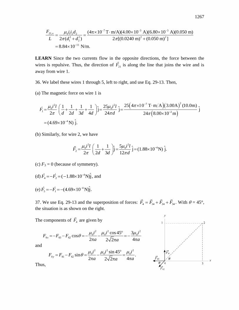
37. We use Eq. 29-13 and the superposition of forces: F F F F4 14 24 34 . With = 45°,
the situation is as shown on the right.
The components of F4 are given by
2 2 2
0 0 04 43 42
cos 45 3cos
2 42 2x
i i iF F F
a aa
p pp
and 2 2 2
0 0 04 41 42
sin 45sin .
2 42 2y
i i iF F F
a aa
p pp
Thus,
CHAPTER 29 1268
1 2 22 22 2 2
1 22 2 0 0 0
4 4 4
4
10 4 T m A 7.50A3 10
4 4 4 4 0.135m
1.32 10 N/m
x y
i i iF F F
a a a
and F4 makes an angle with the positive x axis, where
FHGIKJ
FHGIKJ tan tan .1 4
4
1 1
3162
F
F
y
x
In unit-vector notation, we have
1ˆ ˆ ˆ ˆ(1.32 N/m)[cos162 i sin162 j] ( 1.25 N/m)i (4.17 N/m)jF -4 -4 -510 10 10
38. (a) The fact that the curve in Fig. 29-65(b) passes through zero implies that the
currents in wires 1 and 3 exert forces in opposite directions on wire 2. Thus, current i1
points out of the page. When wire 3 is a great distance from wire 2, the only field that
affects wire 2 is that caused by the current in wire 1; in this case the force is negative
according to Fig. 29-65(b). This means wire 2 is attracted to wire 1, which implies (by
the discussion in Section 29-2) that wire 2’s current is in the same direction as wire 1’s
current: out of the page. With wire 3 infinitely far away, the force per unit length is given
(in magnitude) as 6.27 107
N/m. We set this equal to 12 0 1 2 / 2F i i d . When wire 3
is at x = 0.04 m the curve passes through the zero point previously mentioned, so the
force between 2 and 3 must equal F12 there. This allows us to solve for the distance
between wire 1 and wire 2:
d = (0.04 m)(0.750 A)/(0.250 A) = 0.12 m.
Then we solve 6.27 107
N/m= o i1 i2 /2d and obtain i2 = 0.50 A.
(b) The direction of i2 is out of the page.
39. Using a magnifying glass, we see that all but i2 are directed into the page. Wire 3 is
therefore attracted to all but wire 2. Letting d = 0.500 m, we find the net force (per meter
length) using Eq. 29-13, with positive indicated a rightward force:
0 3 51 2 4| |
2 2 2
i ii i iF
d d d d
which yields 7| | / 8.00 10 N/mF .
40. Using Eq. 29-13, the force on, say, wire 1 (the wire at the upper left of the figure) is
along the diagonal (pointing toward wire 3, which is at the lower right). Only the forces
1269
(or their components) along the diagonal direction contribute. With = 45°, we find the
force per unit meter on wire 1 to be
2 2 2
0 0 01 12 13 14 12 13
2
2
3| | 2 cos 2 cos 45
2 2 2 2 2
4 T m A 15.0A31.12 N/m.
8.50 10 m2 2
i i iF F F F F F
a aa
The direction of 1F is along ˆ ˆˆ (i j) / 2r . In unit-vector notation, we have
1
(1.12 N/m) ˆ ˆ ˆ ˆ(i j) (7.94 N/m)i ( 7.94 N/m)j2
F
-3
-4 -41010 10
41. The magnitudes of the forces on the sides of the rectangle that are parallel to the long
straight wire (with i1 = 30.0 A) are computed using Eq. 29-13, but the force on each of
the sides lying perpendicular to it (along our y axis, with the origin at the top wire and +y
downward) would be figured by integrating as follows:
Fi i
ydy
a
a b
zsides2 0 1
2
.
Fortunately, these forces on the two perpendicular sides of length b cancel out. For the
remaining two (parallel) sides of length L, we obtain
0 1 2 0 1 2
7 2
3
1 1
2 2
4 10 T m/A 30.0A 20.0A 8.00cm 300 10 m3.20 10 N,
2 1.00cm 8.00cm
i i L i i bF
a a d a a b
and F points toward the wire, or j . That is, 3 ˆ(3.20 10 N)jF in unit-vector notation.
42. The area enclosed by the loop L is A d d d 12
24 3 6( )( ) . Thus
27 2 6
0 0 4 T m A 15A m 6 0.20m 4.5 10 T m.cB ds i jA
43. We use Eq. 29-20 2
0 / 2B ir a for the B-field inside the wire ( r a ) and Eq. 29-17
0 / 2B i r for that outside the wire (r > a).
(a) At 0,r 0B .
CHAPTER 29 1270
(b) At 0.0100mr , 7
40
2 2
(4 10 T m/A)(170A)(0.0100m)8.50 10 T.
2 2 (0.0200m)
irB
a
(c) At 0.0200mr a , 7
30
2 2
(4 10 T m/A)(170A)(0.0200m)1.70 10 T.
2 2 (0.0200m)
irB
a
(d) At 0.0400mr , 7
40 (4 10 T m/A)(170A)8.50 10 T.
2 2 (0.0400m)
iB
r
44. We use Ampere’s law: B ds i z 0 , where the integral is around a closed loop and i
is the net current through the loop.
(a) For path 1, the result is
7 6
01
5.0A 3.0A (4 10 T m/A) 2.0A 2.5 10 T m.B ds
(b) For path 2, we find
7 5
02
5.0A 5.0A 3.0A (4 10 T m/A) 13.0A 1.6 10 T m.B ds
45. THINK The value of the line integral B ds is proportional to the net current
enclosed.
EXPRESS By Ampere’s law, we have 0 enc ,B ds i where enci is the current enclosed
by the closed path.
ANALYZE (a) Two of the currents are out of the page and one is into the page, so the
net current enclosed by the path, or “Amperian loop” is 2.0 A, out of the page. Since the
path is traversed in the clockwise sense, a current into the page is positive and a current
out of the page is negative, as indicated by the right-hand rule associated with Ampere’s
law. Thus,
7 6
0 (4 10 T m/A) 2.0A 2.5 10 T m.B ds i
(b) The net current enclosed by the path is zero (two currents are out of the page and two
are into the page), so B ds i z 0 0enc .
LEARN The value of B ds depends only on the current enclosed, and not the shape of
the Amperian loop.
1271
46. A close look at the path reveals that only currents 1, 3, 6 and 7 are enclosed. Thus,
noting the different current directions described in the problem, we obtain
7 3 8
0 07 6 3 5 5 4 10 T m/A 4.50 10 A 2.83 10 T m.B ds i i i i i
47. For r a ,
2
0 enc 0 0 0 00
0 02 2 .
2 2 2 3
r ri J rrB r J r rdr J rdr
r r a a
p p
p p p
(a) At 0,r 0B .
(b) At / 2r a , we have
2 7 2 3 2
70 0
3
(4 10 T m/A)(310A/m )(3.1 10 m / 2)1.0 10 T.
3 3(3.1 10 m)
J rB r
a
(c) At ,r a
7 2 3
70 0 (4 10 T m/A)(310A/m )(3.1 10 m)4.0 10 T.
3 3
J aB r a
48. (a) The field at the center of the pipe (point C) is due to the wire alone, with a
magnitude of
0 wire 0 wire .
2 3 6C
i iB
R R
For the wire we have BP, wire > BC, wire. Thus, for BP = BC = BC, wire, iwire must be into the
page:
0 wire 0
,wire ,pipe .2 2 2
P P P
i iB B B
R R
Setting BC = –BP we obtain iwire = 3i/8 = 3 33(8.00 10 A) /8 3.00 10 A .
(b) The direction is into the page.
49. (a) We use Eq. 29-24. The inner radius is r = 15.0 cm, so the field there is
7
404 10 T m/A 0.800A 500
5.33 10 T.2 2 0.150m
iNB
r
(b) The outer radius is r = 20.0 cm. The field there is
CHAPTER 29 1272
7
404 10 T m/A 0.800A 500
4.00 10 T.2 2 0.200m
iNB
r
50. It is possible (though tedious) to use Eq. 29-26 and evaluate the contributions (with
the intent to sum them) of all 1200 loops to the field at, say, the center of the solenoid.
This would make use of all the information given in the problem statement, but this is not
the method that the student is expected to use here. Instead, Eq. 29-23 for the ideal
solenoid (which does not make use of the coil radius) is the preferred method:
B in iN
FHGIKJ 0 0
where i = 3.60 A, 0.950 m, and N = 1200. This yields B = 0.00571 T.
51. It is possible (though tedious) to use Eq. 29-26 and evaluate the contributions (with
the intent to sum them) of all 200 loops to the field at, say, the center of the solenoid.
This would make use of all the information given in the problem statement, but this is not
the method that the student is expected to use here. Instead, Eq. 29-23 for the ideal
solenoid (which does not make use of the coil diameter) is the preferred method:
B in iN
FHGIKJ 0 0
where i = 0.30 A, 0.25 m, and N = 200. This yields 43.0 10 TB .
52. We find N, the number of turns of the solenoid, from the magnetic field
0 /oB in iN : 0/ .N B i Thus, the total length of wire used in making the
solenoid is
22 2 2 60 10 230 10 130
18 0108
0
2 3
rN
rB
i
. . .
.
m T m
2 4 10 T m / A Am.
7
c hc hb gc hb g
53. The orbital radius for the electron is
rmv
eB
mv
e ni
0
which we solve for i:
31 8
19 7 20
9.11 10 kg 0.0460 3.00 10 m s
1.60 10 C 4 T m A 100 0.0100m 2.30 10 m
0.272A.
mvi
e nr
1273
54. As the problem states near the end, some idealizations are being made here to keep
the calculation straightforward (but are slightly unrealistic). For circular motion (with
speed, v, which represents the magnitude of the component of the velocity perpendicular
to the magnetic field [the field is shown in Fig. 29-20]), the period is (see Eq. 28-17)
T = 2r/v = 2m/eB.
Now, the time to travel the length of the solenoid is /t L v where v|| is the component
of the velocity in the direction of the field (along the coil axis) and is equal to v cos
where = 30º. Using Eq. 29-23 (B = 0in) with n = N/L, we find the number of
revolutions made is t /T = 1.6 106.
55. THINK The net field at a point inside the solenoid is the vector sum of the fields of
the solenoid and that of the long straight wire along the central axis of the solenoid.
EXPRESS The magnetic field at a point P is given by ,s wB B B where Bs and
Bw
are the fields due to the solenoid and the wire, respectively. The direction of Bs is along
the axis of the solenoid, and the direction of Bw is perpendicular to it, so the two fields
are perpendicular to each other, B Bs w . For the net field
B to be at 45° with the axis,
we must have Bs = Bw.
ANALYZE (a) Thus,
00 ,
2
ws w s
iB B i n
d
which gives the separation d to point P on the axis:
di
i n
w
s
2
6 00
2 20 0 10 104 77
3
.
.. .
A
A turns cmcmc hb g
(b) The magnetic field strength is
7 3 52 2 4 10 T m A 20.0 10 A 10 turns 0.0100 m 3.55 10 T.sB B
LEARN In general, the angle B makes with the solenoid axis is give by
1 1 10
0
/ 2tan tan tan
2
w w w
s s s
B i d i
B i n d ni
.
56. We use Eq. 29-26 and note that the contributions to BP from the two coils are the
same. Thus,
CHAPTER 29 1274
7260 0
3 222
8 4 10 T m/A (200) 0.0122A2 88.78 10 T.
5 5 5 5 0.25m2 2P
iR N NiB
RR R
BP is in the positive x direction.
57. THINK The magnitude of the magnetic dipole moment is given by = NiA, where N
is the number of turns, i is the current, and A is the area.
EXPRESS The cross-sectional area is a circle, so A = R2, where R is the radius. The
magnetic field on the axis of a magnetic dipole, a distance z away, is given by Eq. 29-27:
Bz
0
32.
ANALYZE (a) Substituting the values given, we find the magnitude of the dipole
moment to be
22 2300 4.0A 0.025m 2.4A m .Ni R
(b) Solving for z, we obtain
137 213
0
6
4 10 T m A 2.36A m46cm.
2 2 5.0 10 Tz
B
LEARN Note the similarity between 0
3,
2B
z
the magnetic field of a magnetic dipole
and 3
0
1,
2
pE
z the electric field of an electric dipole p (see Eq. 22-9).
58. (a) We set z = 0 in Eq. 29-26 (which is equivalent using to Eq. 29-10 multiplied by
the number of loops). Thus, B(0) i/R. Since case b has two loops,
2 24.0b b a
a a b
B i R R
B i R R .
(b) The ratio of their magnetic dipole moments is
22
2
2 2 1 12 0.50.
2 2
b b b
a a a
iA R
iA R
59. THINK The magnitude of the magnetic dipole moment is given by = NiA, where N
is the number of turns, i is the current, and A is the area.
1275
EXPRESS The cross-sectional area is a circle, so A = R2, where R is the radius.
ANALYZE With N = 200, i = 0.30 A, and R = 0.050 m, the magnitude of the dipole
moment is
2 2200 0.30A m 0.47A m .
LEARN The direction of is that of the normal vector n to the plane of the coil, in
accordance with the right-hand rule shown in Fig. 28-19.
60. Using Eq. 29-26, we find that the net y-component field is
2 2
0 1 0 2
2 2 3/ 2 2 2 3/ 2
1 2
,2( ) 2( )
y
i R i RB
R z R z
where z12 = L
2 (see Fig. 29-74(a)) and z2
2 = y
2 (because the central axis here is denoted y
instead of z). The fact that there is a minus sign between the two terms, above, is due to
the observation that the datum in Fig. 29-74(b) corresponding to By = 0 would be
impossible without it (physically, this means that one of the currents is clockwise and the
other is counterclockwise).
(a) As y , only the first term contributes and (with By = 7.2 106
T given in this case)
we can solve for i1:
2 2 3/ 2 2 3/ 2
1
1 2
0 0
2 3/ 2 6
2( ) 2 [1 ( / ) ]
2(0.040 m)[1 (0.030 m / 0.040 m) ] (7.2 10 T)0.895 A 0.90 A.
4 T m A
y yR z B R L R Bi
R
(b) With loop 2 at y = 0.06 m (see Fig. 29-74(b)) we are able to determine i2 from
2 2
0 1 0 2
2 2 3/ 2 2 2 3/ 2.
2( ) 2( )
i R i R
R L R y
We obtain i2 = (117 13 /50 2.7 A.
61. (a) We denote the large loop and small coil with subscripts 1 and 2, respectively.
Bi
R1
0 1
1
7
5
2
4 10 15
2 0127 9 10
T m A A
mT.
c hb gb g.
.
(b) The torque has magnitude equal to
CHAPTER 29 1276
2
2 2 5
2 1 2 1 2 2 2 1 2 2 2 1
6
| | sin90 1.3A 0.82 10 m 7.9 10 T
1.1 10 N m.
B B N i A B N i r B
62. (a) To find the magnitude of the field, we use Eq. 29-9 for each semicircle ( = rad),
and use superposition to obtain the result:
7
0 0 0
7
(4 10 T m/A) 0.0562A1 1 1 1
4 4 4 0.0572m 0.0936m
4.97 10 T.
i i iB
a b a b
(b) By the right-hand rule, B points into the paper at P (see Fig. 29-7(c)).
(c) The enclosed area is 2 2( ) / 2,A a b which means the magnetic dipole moment
has magnitude
2 2 2 2 3 2(0.0562A)| | ( ) [(0.0572m) (0.0936m) ] 1.06 10 A m .
2 2
ia b
(d) The direction of is the same as the
B found in part (a): into the paper.
63. By imagining that each of the segments bg and cf (which are shown in the figure as
having no current) actually has a pair of currents, where both currents are of the same
magnitude (i) but opposite direction (so that the pair effectively cancels in the final sum),
one can justify the superposition.
(a) The dipole moment of path abcdefgha is
2 2
2 2 2
ˆ ˆ ˆ ˆj i i j
ˆ ˆ6.0A 0.10m j (6.0 10 A m ) j .
bc f gb abgha cde f c ia ia
(b) Since both points are far from the cube we can use the dipole approximation. For
(x, y, z) = (0, 5.0 m, 0),
6 2 2
110
3 3
ˆ(1.26 10 T m/A)(6.0 10 m A) j ˆ(0, 5.0 m, 0) (9.6 10 T) j .2 2 m)
By
64. (a) The radial segments do not contribute to ,PB and the arc segments contribute
according to Eq. 29-9 (with angle in radians). If k^ designates the direction "out of the
page" then
1277
0 0(7 / 4 rad) (7 / 4 rad)ˆ ˆk k4 (4.00 m) 4 (2.00 m)
P
i iB
where i = 0.200 A. This yields B
= 2.75 108
k^ T, or | B
| = 2.75 10
8 T.
(b) The direction is k , or into the page.
65. Using Eq. 29-20,
0
2| |
2
iB r
R
,
we find that r = 0.00128 m gives the desired field value.
66. (a) We designate the wire along y = rA = 0.100 m wire A and the wire along y = rB =
0.050 m wire B. Using Eq. 29-4, we have
60 0net
ˆ ˆ ˆk k ( 52.0 10 T)k.2 2
A BA B
A B
i iB B B
r r
p p
(b) This will occur for some value rB < y < rA such that
0 0
2 2
i
r y
i
y r
A
A
B
B
b g b g .
Solving, we find y = 13/160 0.0813 m.
(c) We eliminate the y < rB possibility due to wire B carrying the larger current. We
expect a solution in the region y > rA where
0 0
2 2
i
y r
i
y r
A
A
B
B
b g b g .
Solving, we find y = 7/40 0.0175 m.
67. Let the length of each side of the square be a. The center of a square is a distance a/2
from the nearest side. There are four sides contributing to the field at the center. The
result is
0
center22
2 24 .
2 2 4 2
i iaB
a aa a
0
p
On the other hand, the magnetic field at the center of a circular wire of radius R is
0 / 2i R (e.g., Eq. 29-10). Thus, the problem is equivalent to showing that
CHAPTER 29 1278
0 02 2 4 2 1
2
i i
a R a R
.
To do this we must relate the parameters a and R. If both wires have the same length L
then the geometrical relationships 4a = L and 2R = L provide the necessary connection:
4 2 .2
Ra R a
Thus, our proof consists of the observation that
4 2 8 2 1
a R R ,
as one can check numerically (that 8 2 1 ).
68. We take the current (i = 50 A) to flow in the +x direction, and the electron to be at a
point P, which is r = 0.050 m above the wire (where “up” is the +y direction). Thus, the
field produced by the current points in the +z direction at P. Then, combining Eq. 29-4
with Eq. 28-2, we obtain F e i r ve 0 2b ge j .k
(a) The electron is moving down: v v j (where v = 1.0 10
7 m/s is the speed) so
160 ˆ ˆi (3.2 10 N) i2
e
e ivF
r
p,
or 16| | 3.2 10 NeF .
(b) In this case, the electron is in the same direction as the current: v v i so
160 ˆ ˆj (3.2 10 N) j2
e
e ivF
r
,
or 16| | 3.2 10 NeF .
(c) Now, v v k so
Fe .k k 0
69. (a) By the right-hand rule, the magnetic field B1 (evaluated at a) produced by wire 1
(the wire at bottom left) is at = 150° (measured counterclockwise from the +x axis, in
the xy plane), and the field produced by wire 2 (the wire at bottom right) is at = 210°.
By symmetry B B1 2d i we observe that only the x-components survive, yielding
1279
501 2
ˆ ˆ2 cos 150 i ( 3.46 10 T)i 2
iB B B
where i = 10 A, = 0.10 m, and Eq. 29-4 has been used. To cancel this, wire b must
carry current into the page (that is, the k direction) of value
5
7
0
2 2 (0.087 m)3.46 10 T 15A
4 10 T m/Ab
ri B
where r 3 2 0 087 . m and Eq. 29-4 has again been used.
(b) As stated above, to cancel this, wire b must carry current into the page (that is, the z
direction).
70. The radial segments do not contribute to B
(at the center), and the arc segments
contribute according to Eq. 29-9 (with angle in radians). If k^ designates the direction
"out of the page" then
0 0 0( rad) ( / 2 rad) ( / 2 rad)ˆ ˆ ˆk k k4 (4.00 m) 4 (2.00 m) 4 (4.00 m)
i i iB
where i = 2.00 A. This yields B
= (1.57 107
T) k^, or 7| | 1.57 10 TB .
71. Since the radius is R = 0.0013 m, then the i = 50 A produces
7
30 (4 10 T m/A)(50 A)7.7 10 T
2 2 (0.0013 m)
iB
R
at the edge of the wire. The three equations, Eq. 29-4, Eq. 29-17, and Eq. 29-20, agree at
this point.
72. (a) With cylindrical symmetry, we have, external to the conductors,
B
i
r0 enc
2
which produces ienc = 25 mA from the given information. Therefore, the thin wire must
carry 5.0 mA.
(b) The direction is downward, opposite to the 30 mA carried by the thin conducting
surface.
73. (a) The magnetic field at a point within the hole is the sum of the fields due to two
current distributions. The first is that of the solid cylinder obtained by filling the hole and
CHAPTER 29 1280
has a current density that is the same as that in the original cylinder (with the hole). The
second is the solid cylinder that fills the hole. It has a current density with the same
magnitude as that of the original cylinder but is in the opposite direction. If these two
situations are superposed the total current in the region of the hole is zero. Now, a solid
cylinder carrying current i, which is uniformly distributed over a cross section, produces a
magnetic field with magnitude
Bir
R
0
22
at a distance r from its axis, inside the cylinder. Here R is the radius of the cylinder. For
the cylinder of this problem the current density is
Ji
A
i
a b
2 2c h ,
where A = (a2 – b
2) is the cross-sectional area of the cylinder with the hole. The current
in the cylinder without the hole is
I JA Jaia
a b1
22
2 2
and the magnetic field it produces at a point inside, a distance r1 from its axis, has
magnitude
BI r
a
ir a
a a b
ir
a b1
0 1 1
2
0 1
2
2 2 2
0 2
2 22 2 2
c h c h .
The current in the cylinder that fills the hole is
I Jbib
a b2
22
2 2
and the field it produces at a point inside, a distance r2 from the its axis, has magnitude
BI r
b
ir b
b a b
ir
a b2
0 2 2
2
0 2
2
2 2 2
0 2
2 22 2 2
c h c h .
At the center of the hole, this field is zero and the field there is exactly the same as it
would be if the hole were filled. Place r1 = d in the expression for B1 and obtain
7
50
2 22 2
(4 10 T m/A) 5.25A (0.0200m)1.53 10 T
2 [(0.0400m) (0.0150m) ]2
idB
a b
for the field at the center of the hole. The field points upward in the diagram if the current
is out of the page.
1281
(b) If b = 0 the formula for the field becomes Bid
a0
22. This correctly gives the field of
a solid cylinder carrying a uniform current i, at a point inside the cylinder a distance d
from the axis. If d = 0 the formula gives B = 0. This is correct for the field on the axis of a
cylindrical shell carrying a uniform current.
Note: One may apply Ampere’s law to show that the magnetic field in the hole is uniform.
Consider a rectangular path with two long sides (side 1 and 2, each with length L) and
two short sides (each of length less than b). If side 1 is directly along the axis of the hole,
then side 2 would also be parallel to it and in the hole. To ensure that the short sides do
not contribute significantly to the integral in Ampere’s law, we might wish to make L
very long (perhaps longer than the length of the cylinder), or we might appeal to an
argument regarding the angle between B and the short sides (which is 90° at the axis of
the hole). In any case, the integral in Ampere’s law reduces to
B ds i
B ds B ds i
B B L
side
rectangleenclosed
sidein hole
side1 side2
zz z
0
1 20
0d i
where Bside 1 is the field along the axis found in part (a). This shows that the field at off-
axis points (where Bside 2 is evaluated) is the same as the field at the center of the hole;
therefore, the field in the hole is uniform.
74. Equation 29-4 gives
iRB
2 2 7 30 10
4321
6
m T
T m AA.
b gc h..
75. THINK In this problem, we apply the Biot-Savart law to calculate the magnetic field
due to a current-carrying segment at various locations.
EXPRESS The Biot-Savart law can be written as
0 0
2 3
r, , .
4 4
i s i s rB x y z
r r
With s s j and ˆ ˆ ˆi j k,r x y z their cross product is
ˆ ˆ ˆ ˆ ˆ ˆ( j) ( i j k) ( i k)s r s x y z s z x
CHAPTER 29 1282
where we have used ˆ ˆ ˆ ˆ ˆj i k, j j 0, and ˆ ˆ ˆj k i. Thus, the Biot-Savart equation
becomes
0
3 22 2 2
ˆ ˆi k, , .
4
i s z xB x y z
x y z
ANALYZE (a) The field on the z axis (at x = 0, y = 0, and z = 5.0 m) is
7 2
10
3/ 222 2
ˆ4 10 T m/A 2.0A 3.0 10 m 5.0 m iˆ0, 0, 5.0 m (2.4 10 T)i.
4 0 0 5.0 m
B
(b) Similarly, B (0, 6.0 m, 0) = 0, since x = z = 0.
(c) The field in the xy plane, at (x, y, z) = (7 m, 7 m, 0), is
211
3/ 22 2 2
ˆ(4 T m/A)(2.0A)(3.0 10 m)( 7.0m)k ˆ7.0 m,7.0 m,0 ( 4.3 10 T)k.
4 7.0 m 7.0 m 0
B
(d) The field in the xy plane, at (x, y, z) = (–3, –4, 0), is
210
3/ 22 2 2
ˆ(4 T m/A)(2.0A)(3.0 10 m)(3.0m)k ˆ3.0m, 4.0m, 0 (1.4 10 T )k.
4 m 4.0m 0
B
LEARN Along the x and z axes, the expressions for B simplify to
0 0
2 2ˆ ˆ,0,0 k, 0,0, i.
4 4
i s i sB x B z
x z
The magnetic field at any point on the y axis vanishes because the current flows in the +y
direction, so r 0.ds
76. We note that the distance from each wire to P is r d 2 0 071. m. In both parts,
the current is i = 100 A.
(a) With the currents parallel, application of the right-hand rule (to determine each of
their contributions to the field at P) reveals that the vertical components cancel and the
horizontal components add, yielding the result:
402 cos 45.0 4.00 10 T2
iB
r
p
1283
and directed in the –x direction. In unit-vector notation, we have 4 ˆ( 4.00 10 T)iB .
(b) Now, with the currents anti-parallel, application of the right-hand rule shows that the
horizontal components cancel and the vertical components add. Thus,
402 sin 45.0 4.00 10 T2
iB
r
p
and directed in the +y direction. In unit-vector notation, we have 4 ˆ(4.00 10 T)jB .
77. We refer to the center of the circle (where we are evaluating B ) as C. Recalling the
straight sections discussion in Sample Problem 29.01 — “Magnetic field at the center of
a circular arc of current,” we see that the current in the straight segments that are collinear
with C do not contribute to the field there. Eq. 29-9 (with = /2 rad) and the right-hand
rule indicates that the currents in the two arcs contribute
0 00
i
R
i
R
b g b g
to the field at C. Thus, the nonzero contributions come from those straight segments that
are not collinear with C. There are two of these “semi-infinite” segments, one a vertical
distance R above C and the other a horizontal distance R to the left of C. Both contribute
fields pointing out of the page (see Fig. 29-7(c)). Since the magnitudes of the two
contributions (governed by Eq. 29-7) add, then the result is
Bi
R
i
RFHGIKJ 2
4 2
0 0
exactly what one would expect from a single infinite straight wire (see Eq. 29-4). For
such a wire to produce such a field (out of the page) with a leftward current requires that
the point of evaluating the field be below the wire (again, see Fig. 29-7(c)).
78. The points must be along a line parallel to the wire and a distance r from it, where r
satisfies Bi
rBwire ext
0
2, or
ri
B
0
3
3
2
100
24 0 10
ext
T m A A
Tm.
c hb gc h .
79. (a) The field in this region is entirely due to the long wire (with, presumably,
negligible thickness). Using Eq. 29-17,
CHAPTER 29 1284
B
i
r
w 0 3
24 8 10
. T
where iw = 24 A and r = 0.0010 m.
(b) Now the field consists of two contributions (which are anti-parallel) — from the wire
(Eq. 29-17) and from a portion of the conductor (Eq. 29-20 modified for annular area):
2 2
0 0 enc 0 0
2 2
0
| |2 2 2 2
w w c i
i
i i i i r RB
r r r r R R
where r = 0.0030 m, Ri = 0.0020 m, Ro = 0.0040 m, and ic = 24 A. Thus, we find 4| | 9.3 10 T.B
(c) Now, in the external region, the individual fields from the two conductors cancel
completely (since ic = iw): B 0.
80. Using Eq. 29-20 and Eq. 29-17, we have
0 01 1 22
2
| | | |2 2
i iB r B
R r
p p
where 4
1 1 20.0040m, 2.8 10 T, 0.010m,r B r and | | .B2
42 0 10 T. Point 2 is
known to be external to the wire since | | | | B B2 1 . From the second equation, we find i =
10 A. Plugging this into the first equation yields R = 5.3 10–3
m.
81. THINK The objective of this problem is to calculate the magnetic field due to an
infinite current sheet by applying Ampere’s law.
EXPRESS The “current per unit x-length” may be viewed as current density multiplied
by the thickness y of the sheet; thus, = Jy. Ampere’s law may be (and often is)
expressed in terms of the current density vector as follows:
B ds J dAz z 0
where the area integral is over the region enclosed by the path relevant to the line integral
(and J is in the +z direction, out of the paper). With J uniform throughout the sheet, then
it is clear that the right-hand side of this version of Ampere’s law should reduce, in this
problem, to
0JA = 0J yx = 0x.
ANALYZE (a) Figure 29-84 certainly has the horizontal components of B drawn
correctly at points P and P', so the question becomes: is it possible for B to have vertical
components in the figure?
1285
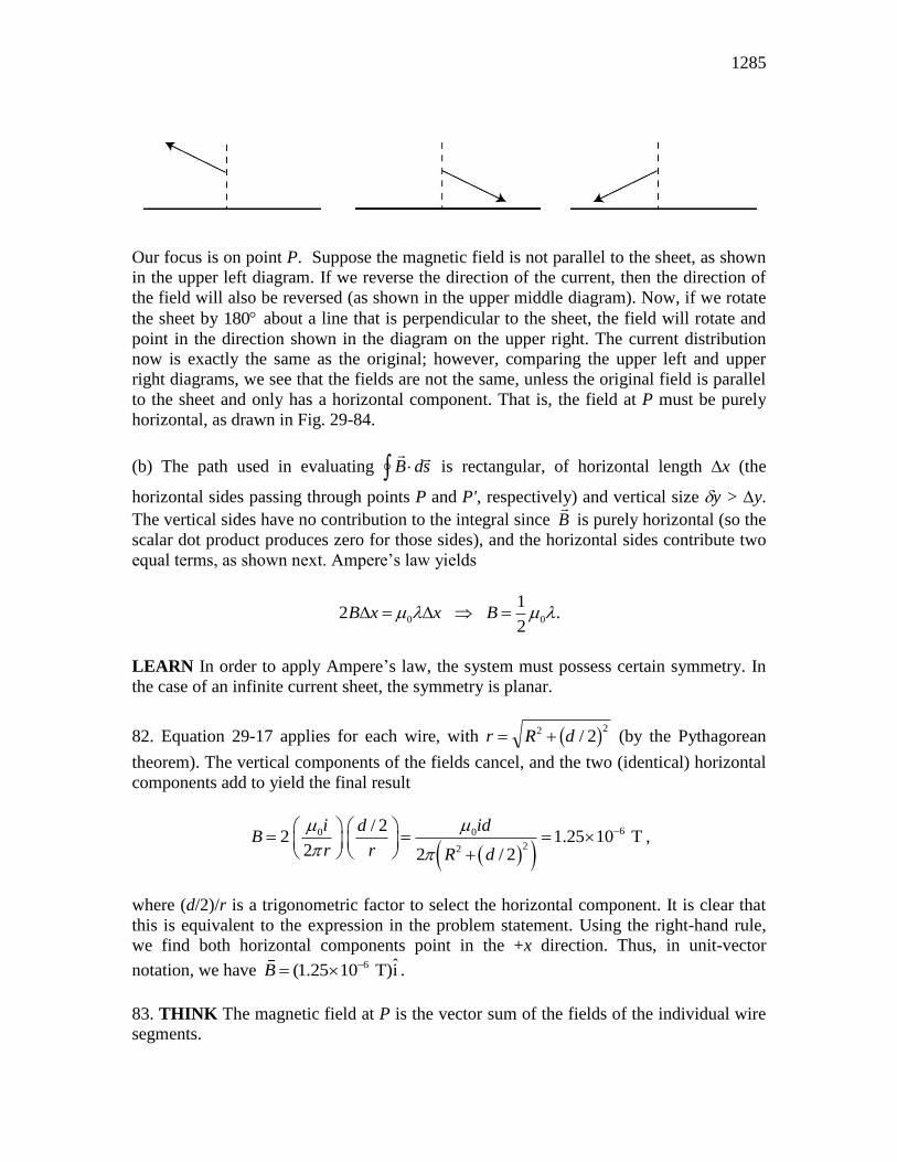
Our focus is on point P. Suppose the magnetic field is not parallel to the sheet, as shown
in the upper left diagram. If we reverse the direction of the current, then the direction of
the field will also be reversed (as shown in the upper middle diagram). Now, if we rotate
the sheet by 180 about a line that is perpendicular to the sheet, the field will rotate and
point in the direction shown in the diagram on the upper right. The current distribution
now is exactly the same as the original; however, comparing the upper left and upper
right diagrams, we see that the fields are not the same, unless the original field is parallel
to the sheet and only has a horizontal component. That is, the field at P must be purely
horizontal, as drawn in Fig. 29-84.
(b) The path used in evaluating B dsz is rectangular, of horizontal length x (the
horizontal sides passing through points P and P', respectively) and vertical size y > y.
The vertical sides have no contribution to the integral since B is purely horizontal (so the
scalar dot product produces zero for those sides), and the horizontal sides contribute two
equal terms, as shown next. Ampere’s law yields
0 0
12 .
2B x x B
LEARN In order to apply Ampere’s law, the system must possess certain symmetry. In
the case of an infinite current sheet, the symmetry is planar.
82. Equation 29-17 applies for each wire, with r R d 2 22/b g (by the Pythagorean
theorem). The vertical components of the fields cancel, and the two (identical) horizontal
components add to yield the final result
60 0
22
/ 22 1.25 10 T
2 2 / 2
i iddB
r r R d
,
where (d/2)/r is a trigonometric factor to select the horizontal component. It is clear that
this is equivalent to the expression in the problem statement. Using the right-hand rule,
we find both horizontal components point in the +x direction. Thus, in unit-vector
notation, we have 6 ˆ(1.25 10 T)iB .
83. THINK The magnetic field at P is the vector sum of the fields of the individual wire
segments.
CHAPTER 29 1286
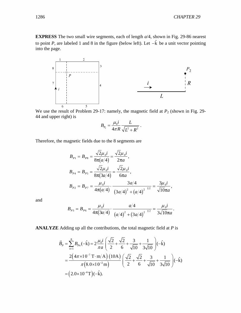
EXPRESS The two small wire segments, each of length a/4, shown in Fig. 29-86 nearest
to point P, are labeled 1 and 8 in the figure (below left). Let k be a unit vector pointing
into the page.
We use the result of Problem 29-17: namely, the magnetic field at P2 (shown in Fig. 29-
44 and upper right) is
2 2 24P
i LB
R L R
.
Therefore, the magnetic fields due to the 8 segments are
B Bi
a
i
a
B Bi
a
i
a
B Bi
a
a
a a
i
a
P P
P P
P P
1 8
0 0
4 5
0 0
2 7
0
2 21 2
0
2
8 4
2
2
2
8 3 4
2
6
4 4
3 4
3 4 4
3
10
b g
b g
b g b g b g
,
,
,
and
B Bi
a
a
a a
i
aP P3 6
0
2 21 2
0
4 3 4
4
4 3 4 3 10
b g b g b g.
ANALYZE Adding up all the contributions, the total magnetic field at P is
80
1
4
2 2 3 1ˆ ˆ( k) 2 ( k)2 6 10 3 10
2 4 T m A 10A 2 2 3 1 ˆ( k)2 6m 10 3 10
ˆ2.0 10 T ( k).
P Pn
n
iB B
a
1287
LEARN If point P is located at the center of the square, then each segment would
contribute
01 2 8
2,
4P P P
iB B B
a
making the total field
0center 1
8 28 .
4P
iB B
a
84. (a) All wires carry parallel currents and attract each other; thus, the “top” wire is
pulled downward by the other two:
0 05.0A 3.2A 5.0A 5.0A
2 0.10m 2 0.20m
L LF
where L = 3.0 m. Thus, F 17 10 4. N.
(b) Now, the “top” wire is pushed upward by the center wire and pulled downward by the
bottom wire:
0 0 5
5.0A 3.2A 5.0A 5.0A| | 2.1 10 N
2 0.10m 2 0.20m
L LF
.
85. THINK The hollow conductor has cylindrical symmetry, so Ampere’s law can be
applied to calculate the magnetic field due to the current distribution.
EXPRESS Ampere’s law states that 0 enc ,B ds i where enci is the current enclosed by
the closed path, or Amperian loop. We choose the Amperian loop to be a circle of radius
r and concentric with the cylindrical shell. Since the current is uniformly distributed
throughout the cross section of the shell, the enclosed current is
2 2 2 2
enc 2 2 2 2
r b r bi i i
a b a b
.
ANALYZE (a) Thus, in the region b < r < a, we have
2 2
0 enc 0 2 22
r bB ds rB i i
a b
which gives Bi
a b
r b
r
FHG
IKJ
0
2 2
2 2
2c h .
(b) At r = a, the magnetic field strength is
CHAPTER 29 1288
0
2 2
2 2
0
2 2
i
a b
a b
a
i
a
FHG
IKJ c h .
At r b B r b , 2 2 0 . Finally, for b = 0
Bi
a
r
r
ir
a
0
2
2
0
22 2
which agrees with Eq. 29-20.
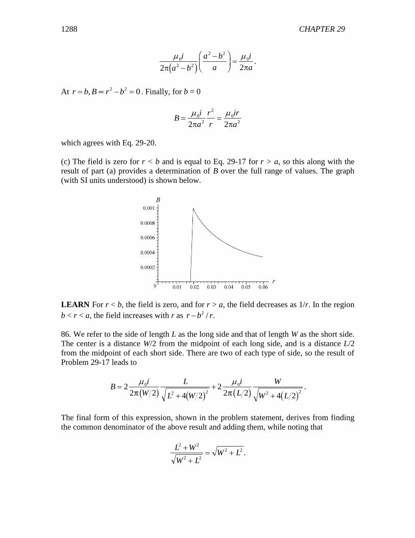
(c) The field is zero for r < b and is equal to Eq. 29-17 for r > a, so this along with the
result of part (a) provides a determination of B over the full range of values. The graph
(with SI units understood) is shown below.
LEARN For r < b, the field is zero, and for r > a, the field decreases as 1/r. In the region
b < r < a, the field increases with r as 2 / .r b r
86. We refer to the side of length L as the long side and that of length W as the short side.
The center is a distance W/2 from the midpoint of each long side, and is a distance L/2
from the midpoint of each short side. There are two of each type of side, so the result of
Problem 29-17 leads to
Bi
W
L
L W
i
L
W
W L
2
2 2 4 22
2 2 4 2
0
2 2
0
2 2
b g b g b g b g.
The final form of this expression, shown in the problem statement, derives from finding
the common denominator of the above result and adding them, while noting that
L W
W LW L
2 2
2 2
2 2
.
1289
87. (a) Equation 29-20 applies for r < c. Our sign choice is such that i is positive in the
smaller cylinder and negative in the larger one.
0
2, .
2
irB r c
c
(b) Equation 29-17 applies in the region between the conductors:
0 , .2
iB c r b
r
(c) Within the larger conductor we have a superposition of the field due to the current in
the inner conductor (still obeying Eq. 29-17) plus the field due to the (negative) current in
that part of the outer conductor at radius less than r. The result is
2 2
0 0
2 2, .
2 2
i i r bB b r a
r r a b
If desired, this expression can be simplified to read
Bi
r
a r
a b
FHG
IKJ
0
2 2
2 22.
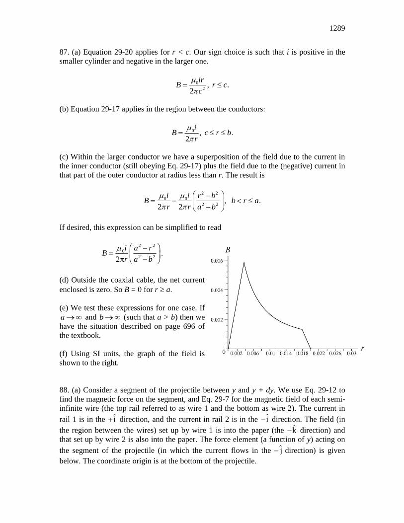
(d) Outside the coaxial cable, the net current
enclosed is zero. So B = 0 for r a.
(e) We test these expressions for one case. If
a and b (such that a > b) then we
have the situation described on page 696 of
the textbook.
(f) Using SI units, the graph of the field is
shown to the right.
88. (a) Consider a segment of the projectile between y and y + dy. We use Eq. 29-12 to
find the magnetic force on the segment, and Eq. 29-7 for the magnetic field of each semi-
infinite wire (the top rail referred to as wire 1 and the bottom as wire 2). The current in
rail 1 is in the i direction, and the current in rail 2 is in the i direction. The field (in
the region between the wires) set up by wire 1 is into the paper (the k direction) and
that set up by wire 2 is also into the paper. The force element (a function of y) acting on
the segment of the projectile (in which the current flows in the j direction) is given
below. The coordinate origin is at the bottom of the projectile.
CHAPTER 29 1290
1 2 1 2 1 2
0 0
ˆ ˆ ˆj j i
i .4 2 4
dF dF dF idy B dy B i B B dy
i ii dy
R w y y
Thus, the force on the projectile is
2 2
0 01 1 ˆ ˆi ln 1 i.4 2 2
R w
R
i i wF dF dy
R w y y R
(b) Using the work-energy theorem, we have
K mv W F ds FLf z 12
2
ext
.
Thus, the final speed of the projectile is
vW
m m
i w
RLf
FHGIKJ
FHGIKJ
LNM
OQP
L
NMM
O
QPP
2 2
21
2 4 10 450 10 1 12 4 0
2 10 10
2 3 10
1 2
0
21 2
7 32
3
1 2
3
ext
T m / A A cm / 6.7cm m
kg
m / s.
/ /
/
ln
ln . .
.
c hc h b gb gc h