Embed Size (px)
Citation preview
1
Functioning of a Fume Hood
Purpose: The purpose of this paper is to review the basic tenets of Fume Hood design, trace its fireplace origins through its evolution to become a vital safety exposure protection device for lab workers handling hazardous chemicals. To understand how laboratory fume hoods work requires a review of key errors that furniture manufactures, architects, interior decorators, and industrial hygienists (IH) made. The laboratory fume hood is the most misunderstood, complicated, mechanical product ever designed, specified, manufactured, and tested by a usually non-qualified entity. The fume hood is nothing more than an extension of the mechanical exhaust duct system. In fact, the lab itself is also nothing more than the extension of the same exhaust system. You can think of the fume hood as just a “bump” in the exhaust duct system. The concern is that a lab worker spends his/her day working in an exhaust duct plenum surrounded by hazardous chemicals.12345678910111213 The fume hood would be the most complicated mechanical duct any PE could be asked to design, specify, and have built by a
1 Occupational Safety and Health 29 CFR Part 1910 Occupational Exposure to Hazardous chemicals in Laboratories 2 “Beyond Ethical Imperatives in Occupational Health and Safety” Steve Levine Univ. of Mich. Occupational Health and Safety Policy Group 3 “Mary’s Story A Lab Design Gone Wrong” J. Koenigsberg, HPAC Dec 2000 4 “The Unintended Practice of Using Employee Health as an Indicator of Laboratory Hood Performance” T. Smith, ECT Inc. June/2003 5 “Pregnancy Outcome Following Gestational Exposure to Organic Solvents” S. Khattak, MD et al “Journal of the American Medical Association” March 1999 6 “AMA Study: Pregnant Lab Employees Risk Birth Defects When Exposed to Organic Solvents” Environmental Laboratory Washington Report Vol. 10, Issue 7 7 “The Effects of Workplace Hazards on Female Reproductive Health” NIOSH Pub No. 99-104 8 “Father’s Occupational Exposure Linked to Birth Defects” Sin-Eng Chia, MD “Journal of Occupational and Environmental Medicine September 2004 9 “Is Your Laboratory Safe, Is your Fume Hood Safe” R Morris et al, “Engineered Systems” January 2000 10 “Demonstrating Leadership Redux”, H.J. Elston “Journal of Chemical Health and Safety” September/October 2009 11 “A Question of Design” R Morris et al, “Occupational Health & Safety” May 2002 12 “Oil Company Confronts Cluster of Brain Tumors” D Barboza, New York Times April 6,1999 13 “In an AMOCO/BP Lab, Researchers Hunt for Colleagues’ Killer” K Johnson, USA Today April 13,1999
2
qualified sheet metal contractor. Unfortunately, the fume hood is not designed, performance specified, or tested by a qualified PE but rather by an architect or interior decorator and treated like a magical piece of furniture. This very complex mechanical ductwork also has more applicable Laws, Codes, and Standards to be followed than any other mechanical device on the lab project.141516 Its proper operation directly impacts the life and safety of the lab worker and significantly drives the mechanical system construction cost. The fundamental error in fume hood design is that the most technically qualified/licensed person is not designing the fume hoods. This explains why fume hoods generally fail to protect workers from hazardous chemical vapors, splash or explosion. The fume hoods construction evolved, over time, by the furniture industry to a detailed design specification supplied by the architect or interior decorator as a piece of furniture.17 This design flaw has proven to place higher value on esthetics than worker safety. This explains why, to this day, lab supply make-up air diffusers are located improperly for worker safety--they are “picked” for style over function.1819 This same esthetic ideology is more important to the fume hood design than its function. The fume hood’s operation can only be accurately explained by the study of fluids “incompressible flow”. The architect, interior decorator, and IH never studied this heavy math based subject. Fume hoods follow the same laws of physics as fans and pumps and there is no such thing as a common operating curve for any series of fans or pumps. If a group of highly qualified engineers designed the best fan ever created, and accurately proportionally scaled up this great design, it would be that the larger fan would follow a similar operating curve as the smaller fan. When the fume hood increases in size, the architect only changes one dimension (length) because the other dimensions are fixed by the size of the door the hood must pass through. The manufacturer, architect, interior decorator, and IH mistakenly claim all fume hoods, regardless of length, operate on the same operating curve and this is impossible. The industry also
14 Occupational Safety and health Administration 29 CFR 1910 Hazardous Chemicals in Labs 15 2011NFPA 45 Standard on Fire Protection for Laboratories Using Chemicals 16 2012 AIHA Z 9.5 Lab Ventilation Standard 17 2009 AIA Master Spec Section 115313 “Laboratory Fume Hoods” 18 “Building a Safe Laboratory Environment” J Koenigsberg HPAC June 1987 19 “Influence of Room Air Supply on Laboratory Hoods” K Caplan et al American Industrial Hygiene Association Journal October 1982

3
claims that regardless of manufacturer, all hoods operate on the same curve that is also a mathematical impossibility due to dimensional variances and internal structure differences affecting airflow internal patterns between designs. The fume hood’s mathematical operation is similar to a high performance boiler or well designed fireplace but bares almost no similarity to a piece of oddly designed furniture. Fume hood manufacturers make a hood size and style for every budget and everything they make works “great” when equipped with their magical 100 to 120 fpm face velocity. The furniture industry teaches if the fume hood does not work well, the PE and HVAC contractor are to blame since all hoods work “great” at the factory.
The Lab Furniture industry sold the false notion that face velocity “captured” harmful vapors and the “higher the face velocity the better it would work”. The actual mathematical facts are that the fume hood “contains” harmful vapors through the stabilization of the internal airflow pattern and does not “capture” them. This error on fume hood face velocity drove all other operating myths and design errors that supported face velocity. Myths such as since the fume hood was a laminar airflow device, the bypass air should be introduced into the fume hood above the sash opening to maintain a uniform face velocity, the work surface airfoil should direct air across the work surface and the rear baffle slots adjusted for changes in experiments air density and/or temperature are all false. If the fume hood works by “containing” versus “capturing” the harmful vapors, then the fume hoods performance failure is a function of the fume hood design and manufacturing. This has become a very difficult issue for the Laboratory Furniture Industry to admit since they may be held accountable for all past and present product design errors and possible ill effects to those using them. An even greater safety problem is being created. The Laboratory Furniture Industry initially ignored and then sold against the ANSI/ASHRAE 110 tracer gas performance testing method but their marketers soon realized they had a sales advantage using the “As Manufactured” (AM) empty hood performance test. By literally eliminating or minimizing any exhaust within the fume hood top section, they could create a better performing hood as long as the hood remained empty, handled no heat producing experiments or rotational equipment.2021 The architect and lab planner was successfully sold that as long as the hood works 20 “The Effect of Thermal Loading on Laboratory Fume Hood Performance” J Johnston et al, “Applied Occupational & Environ. Hygiene” Vol. 15,2000 21 “Balancing Safety and energy Efficiency from Lab Design Through Operation” S Reynolds (CAES) & F Turco (Pfizer) 2005 Labs 21
4
empty at the factory when later “As Used” (AU) tracer gas testing failed, it is someone else’s problem. Unfortunately the architect and lab planners buy in to this “kick the can down the road” at the expense of worker safety. Unfortunately a perfect storm is now being created. This fume hood manufactures short-term method to camouflage fume hood poor performance has even now created a more serious issue. Fume hood control marketers have reduced the exhaust for the minimum fume hood lower explosive purge rate in order to sell more energy control savings “stuff” by assuming perfect mixing conditions. Unfortunately, no one is taking in account the upper hood stagnation caused by little or even no exhaust. Thus, given the right set of circumstances, 3.25 g, an insignificant amount of acetone, is capable of producing the same energy as 10 g of dynamite or 7.32 g of RDX used in an Army fume hood explosion experiment with disastrous results.22 As the only purpose for a fume hood is for worker protection in our litigious society, it could mean product liability and recall demands by their customers.232425262728293031 The latest ANSI/AIHA Z9.5 2012 Lab Standard no longer even suggests that face velocity is a measurement of fume hood performance safety. However, face velocity is such an easy concept to sell to the architect, interior decorator, and IH they have refused to abandon this simple prescriptive notion. Why? Face
22 “The Explosion-Resistant Fume hood” J Koenigsberg at el “American Laboratory” February 1986 23 “Myth of Face Velocities In Fume Hoods” C Connell Laboratory Fume Hood Testing Occupational Health and Safety 24 “A Review of Published Quantitative Experimental Studies of Factors Affecting Laboratory Fume Hood Performance” K. Ahn et al “Journal of Occupational and Environmental Hygiene” November 2008 25 “Reducing Employee Exposure Potential Using the ANSI/ASHRAE 110 Method of Testing Performance of Laboratory Fume Hoods as a Diagnostic Tool” K Maupin’s et al “AIHA Journal” Vol. 59, No.2, pp133-138 26 “An Evaluation of Four Quantitative Laboratory Fume Hood Performance Test Methods” L Woodrow Los Alamos National Laboratory UC-41 November 1987 27 “Containment Testing for Occupied and Unoccupied Laboratory Chemical Hoods” P Greenly et al ASHRAE Transactions CH-99-9-1 PP 733-737 28 “Use of Average Face Velocity as an Indicator of Laboratory Hood Performance” T Smith ECT Inc 29 OSHA Letter of Interpretation to the Honorable Robert Torricelli, United State Senate, from OSHA R. Fairfax Director of Directorate of Compliance Programs, April 4, 2001 30 NIOSH Letter of Interpretation to the Honorable Robert Torricelli, United States Senate, from L. Fine MD, Acting Director, May 3,2001 31 “Fume Hood Myths” T Wilson PE Appendix A, TABB/SMACNA/NEMI Fume Hood Study Guide
5
velocity makes their jobs easier and fume hood performance failures become someone else’s problem (PE or HVAC contractor). As the 2012 AIHA Z9.5 clearly makes the case, to continue to use fume hood face velocity as the fume hood performance test and indicator denies the worker their legal right to medical evaluation when exposed to hazardous chemicals under Federal/State OSHA Law. These facts, and the Scientific Equipment & Furniture Association (SEFA) trade group’s Lab fume hood standard, clearly state fume hood face velocity is not a measurement of worker safety. Even that will not stop the architect, interior decorator or the IH from abandoning fume hood the face velocity myth. IH are generally made in school following their technically error filled “Lab Prudent Practice” college textbook and are trained to never deviate from the safety practices they are taught. Their industry admits that their certification program has serious issues. There are over 300 private companies offering IH certification programs and one even offering a license for a price. The problem is who certifies the certifier? Unlike the PE who is license by the State, who certifies the information the IH is being certified too? They generally have not studied fluids in college, which is a requirement in most engineering curriculums. What complicates the issue is many of the leading IH may have received advance degrees based on studies using face velocity as the indicator for fume hood performance. One of the tragedies is the unwillingness of the IH college textbook “Prudent Practice in the Laboratory” to correct their mistakes on how fume hoods work and what OSHA requires in this country to protect the laboratory worker from hazardous chemicals. Their textbooks only explain the importance of face velocity as a function for fume hood performance and ignore OSHA’s requirement for routine performance based monitoring thereby denying the worker their rights under Federal Law for medical evaluation when exposed to hazardous chemicals. These issues have placed the laboratory employer and owners in jeopardy since they adopted their worker safety plan based on their IH false claim that fume hood face velocity protects workers. Because of the intentional failure of “Prudent Practice Handbook” most Universities and Corporation policies use face velocity as the primary measure for worker safety and do not follow OSHA’s mandate for routine worker exposure monitoring for hazardous chemicals as defined in the Law. This is a tremendous risk, but like the fume hood manufacturer, the IH does not want to bring attention to their past mistakes with worker safety and possibly face litigation from the lab workers they harmed. Personal liability is also why Cal OSHA has blocked any attempt to correct its prescriptive requirement on fume hood face velocity language in the code and then refuses to enforce Federal OSHA’s routine
6
performance based monitoring requirements even though also part of their same Code language. California leads the nation in class action lawsuits for workers exposed to harmful chemicals in the work place. If Cal OSHA admitted to their worker safety errors, then Cal OSHA’s past and present code enforcement officials could possibly expose themselves to lawsuits. Failure to follow OSHA became the bases of the felony charges against UCLA and others in the death of a lab worker. The reason the architect or interior decorator takes on the legal design specification responsibilities of the chemical fume hood is its intrinsic value to the project and they will generally be the lead project designer with primary contractual responsibilities.
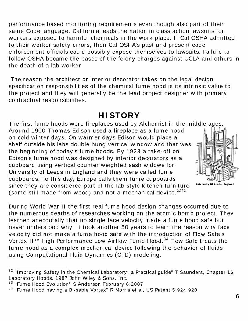
HISTORY The first fume hoods were fireplaces used by Alchemist in the middle ages. Around 1900 Thomas Edison used a fireplace as a fume hood on cold winter days. On warmer days Edison would place a shelf outside his labs double hung vertical window and that was the beginning of today’s fume hoods. By 1923 a take-off on Edison’s fume hood was designed by interior decorators as a cupboard using vertical counter weighted sash widows for University of Leeds in England and they were called fume cupboards. To this day, Europe calls them fume cupboards since they are considered part of the lab style kitchen furniture (some still made from wood) and not a mechanical device.3233
During World War II the first real fume hood design changes occurred due to the numerous deaths of researches working on the atomic bomb project. They learned anecdotally that no single face velocity made a fume hood safe but never understood why. It took another 50 years to learn the reason why face velocity did not make a fume hood safe with the introduction of Flow Safe’s Vortex II™ High Performance Low Airflow Fume Hood.34 Flow Safe treats the fume hood as a complex mechanical device following the behavior of fluids using Computational Fluid Dynamics (CFD) modeling.
32 “Improving Safety in the Chemical Laboratory: a Practical guide” T Saunders, Chapter 16 Laboratory Hoods, 1987 John Wiley & Sons, Inc. 33 “Fume Hood Evolution” S Anderson February 6,2007 34 “Fume Hood having a Bi-sable Vortex” R Morris et al, US Patent 5,924,920
7
Marketers introduced the horizontal sash style hoods during the 1970’s OPEC oil embargo to reduce fume hood energy operating costs.35 Horizontal sashes are recommended in the ACGIH handbook as a means to safely reduce energy consumption and if designed correctly, splash and explosion protection in fume hoods. Unfortunately, the economics of a project (not the more important ergonomics) often means the cheapest product available gets the order. Vertical sash counter weighted windows are cheaper to make than horizontal sashes. In an effort to make them cheaper the horizontal panels were designed wide and used tracks that were prone to collecting debris thereby limiting worker accessibility and protection. The fume hood user generally hates horizontal sash panels because the wide panel size restricted the full use of the hood, the panels would get stuck and proved difficult to move. Users consider them an energy idea that is inconvenient. It never occurred to most workers, that had the horizontal sashes had been designed for the proper width, movement and service that they were much safer than vertical sashes.36
The Anatomy of a Hood The first fume hoods were fireplaces used by Alchemists who were trying to convert base materials into gold. The following sectional views illustrates that a fireplace and fume hood look similar. When fireplaces were used as fume hoods, lab workers placed candles on the smoke shelf to create exhaust (thermal lift). Gas rings later replaced the candles and eventually electric exhaust fans were added about the time fume hoods became laboratory furniture. The fume hoods vertical sash handle is the fireplaces lintel. The hearth opening is the fume hood face opening. Those experienced with fireplaces have seen smoke
35 “Evaluating a HOPEC Lab Fume Hood” J Koenigsberg et al HPAC December 1991 36 2011 NFPA 45 “Standard on Fire Protection for Laboratories Using Chemicals”
8
“rolls out” at the lintel and reverse back in to the fireplace. This cyclical pattern is randomly produced from disruptive energy pressure waves and is precisely what happens when a fume hood fails.3738 This also illustrates why less than average height shorter workers are exposed to higher vapor spills versus taller workers.39 The shorter worker’s-breathing zone is closer to the vertical sash handle/lintel where a fume hood more likely spills. Looking inside a fireplace you’ll observe smoke rolling in the top section. This roll is formally called a vortex and the top section a vortex chamber. The same vortex formation happens within a fume hood and when this vortex collapses the fireplace fails leading to reversals. When the vortex reestablishes, the smoke returns back within the fireplace vortex chamber.40 This episodically containment, then loss of containment, is the same for a fume hood because fireplaces and fume hoods operate similarly. What makes a poorly designed fireplace fail will also make a poorly designed fume hood fail. A poorly designed fireplace is sensitive to the same environmental energy pressure wave upsets as a fume hood. Loading and crosscurrents, space pressure changes from doors opening and closing, building stack effect, pressure fluctuations, walk-bys, and wind turbulence at its discharge stack are all examples of wave upsets. All of these environmental episodes produce energy pressure waves that cause a weakly formed vortex to collapse, then spill, then re-establish and then collapse again. If you had a poorly operating fireplace and tore it down would you re-build the fireplace using the same dimensions or would you change some dimension(s)? Most would change a dimension, since if not its Einstein’s definition of insanity, but which one and how much? If you look at the fireplace illustration above, please note in the lower table, when you change the hearth opening size all the other dimensions change. Previously, we highlighted a design flaw in most fume hoods designs only change one dimension (length) to preserve its ability to be carried through a door like any other piece of furniture.
37 “A True Paradigm Shift on How Fume Hoods will be Designed and Controlled in the 21st Century” R Morris May 9,1998 38 “The Impact of Fume Hood Vortex Development and Fume Hood Performance” R Morris 1995 39 “Is Your Laboratory Safe? Is Your Fume Hood Safe?” R Morris et al “Engineered Systems” January 2000 40 “Suggested Improvements to Prevent the Escape of Fume from Beneath the Sash of a Fume hood Cupboard” P Robertson et al AINA Vol. 23,1980
9
MYTH-“Fume Hood’s are a Laminar Air Flow Device”
Fume hoods are sold as laminar devices that support the face velocity myth. No one questions it; even though anyone who has ever “smoked tested” a hood has never seen a straight arrow laminar smoke pattern. The following illustrations can be found in the American Society of Heating, Refrigeration and Air-Conditioning Engineers ASHRAE 1999 and 2003 HVAC Application Handbooks on laboratories. Until an engineer published an article in 1998 mathematically describing fume hoods worked based on Reynolds numbers ASHRAE also followed the laminar airflow myth promoted by the fume hood manufacturers’ and industrial hygienist college textbook.41 Engineers are taught to solve problems with their best work done when they “think outside the box”. Engineers will also admit their mistakes, so ASHRAE removed the fume hood’s laminar pattern illustration from their 2003 Handbook. Unfortunately, the most often used industrial hygienist’s textbook on laboratory operation is “Prudent Practices in the Laboratory”. The industrial hygienist’s
41 “A True Paradigm Shift on How Fume Hoods Will be Designed and Controlled in the 21st Century” R Morris May 5, 1998
10
college textbook still promotes the “fume hood is laminar” and “face velocity is what makes a fume hood safe” myths. This explains why today’s graduating industrial hygienists may not know how fume hoods work or what OSHA actually requires for worker safety. The textbook reflects “bias” against following Federal/State OSHA Laws and intentionally denies workers rights for medical evaluation when exposed to hazardous chemicals even though Congress forced AIHA Z9.5 2012 to correct wording in the standard to reflect Law.
Many architects and industrial hygienists may think these are minor issues, but they are not. The industrial hygienist’s insistence on using face velocity as the measurement of safety, and not following OSHA’s performance monitoring mandate for hazardous chemicals, has placed lab worker’s safety in jeopardy and the organizations they work for in unnecessary legal peril.
Why Do We Know That Fume Hoods are Not Laminar?
When studying any device used to convey airflow or fluid the first step is to determine the “regime turbulence factor” by calculating the devices Reynolds Number (Re).
The Reynolds number is a dimensionless number that gives a measure of the ratio of inertial forces (VP) to viscous forces (u / L) and explains how these two types of forces create the airflow conditions. Re
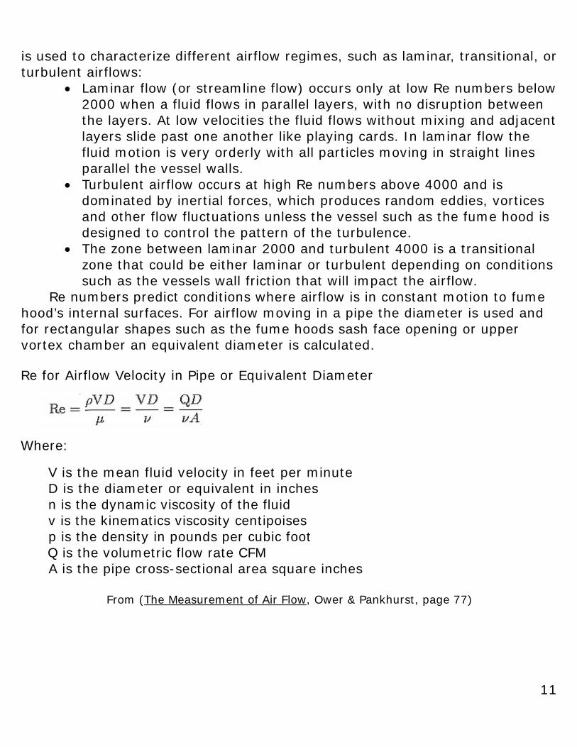
11
is used to characterize different airflow regimes, such as laminar, transitional, or turbulent airflows:
• Laminar flow (or streamline flow) occurs only at low Re numbers below 2000 when a fluid flows in parallel layers, with no disruption between the layers. At low velocities the fluid flows without mixing and adjacent layers slide past one another like playing cards. In laminar flow the fluid motion is very orderly with all particles moving in straight lines parallel the vessel walls.
• Turbulent airflow occurs at high Re numbers above 4000 and is dominated by inertial forces, which produces random eddies, vortices and other flow fluctuations unless the vessel such as the fume hood is designed to control the pattern of the turbulence.
• The zone between laminar 2000 and turbulent 4000 is a transitional zone that could be either laminar or turbulent depending on conditions such as the vessels wall friction that will impact the airflow.
Re numbers predict conditions where airflow is in constant motion to fume hood’s internal surfaces. For airflow moving in a pipe the diameter is used and for rectangular shapes such as the fume hoods sash face opening or upper vortex chamber an equivalent diameter is calculated.
Re for Airflow Velocity in Pipe or Equivalent Diameter
Where:
V is the mean fluid velocity in feet per minute D is the diameter or equivalent in inches
n is the dynamic viscosity of the fluid v is the kinematics viscosity centipoises p is the density in pounds per cubic foot
Q is the volumetric flow rate CFM A is the pipe cross-sectional area square inches
From (The Measurement of Air Flow, Ower & Pankhurst, page 77)
12
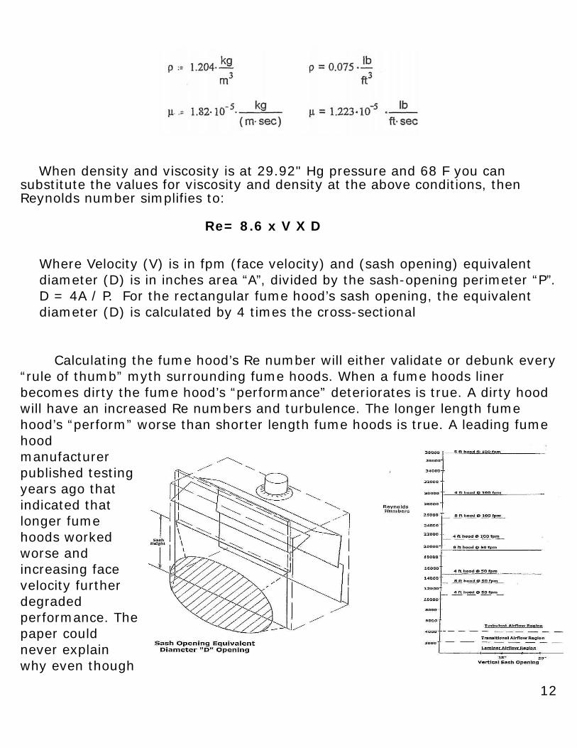
When density and viscosity is at 29.92" Hg pressure and 68 F you can substitute the values for viscosity and density at the above conditions, then Reynolds number simplifies to:
Where Velocity (V) is in fpm (face velocity) and (sash opening) equivalent diameter (D) is in inches area “A”, divided by the sash-opening perimeter “P”. D = 4A / P. For the rectangular fume hood’s sash opening, the equivalent diameter (D) is calculated by 4 times the cross-sectional
Calculating the fume hood’s Re number will either validate or debunk every “rule of thumb” myth surrounding fume hoods. When a fume hoods liner becomes dirty the fume hood’s “performance” deteriorates is true. A dirty hood will have an increased Re numbers and turbulence. The longer length fume hood’s “perform” worse than shorter length fume hoods is true. A leading fume hood manufacturer published testing years ago that indicated that longer fume hoods worked worse and increasing face velocity further degraded performance. The paper could never explain why even though
Re= 8.6 x V X D
13
the paper was a complete reversal to the myth about face velocity. Longer hoods have increased Re numbers and higher turbulence. The original ASHRAE study by Caplan and Knutson that created today’s tracer gas ASHRAE 110 standard indicated that fume hoods at 50 fpm face velocity appeared to “perform better” than fume hoods at increased face velocity but again could not explain why. This improved lower face velocity performance for some hoods was even reported back in the sixties but again no one could explain why. That was also true because lower face velocity decreases the Re numbers and reduces turbulence and depending on the internal fume hood design can improve its performance. The following graph illustrates different operating Re numbers between a four-foot and eight-foot standard bench hood at either 50 fpm or 100 fpm face velocity. You can see the dramatic changes in Re from changes in face velocity and hood length.
Fume hoods are VERY TURBULENT even at reduced face velocities and were never laminar. Why some fume hoods “work” better than others is solely about their internal design. Why conventional narrow depth “Walk-in” (floor mounted) fume hoods perform poorly is their Re numbers are double that of bench hoods indicating twice the turbulence and are unsafe to use for worker protection.
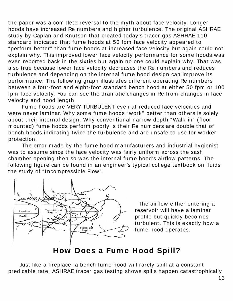
The error made by the fume hood manufacturers and industrial hygienist was to assume since the face velocity was fairly uniform across the sash chamber opening then so was the internal fume hood’s airflow patterns. The following figure can be found in an engineer’s typical college textbook on fluids the study of “Incompressible Flow”.
The airflow either entering a reservoir will have a laminar profile but quickly becomes turbulent. This is exactly how a fume hood operates.
How Does a Fume Hood Spill? Just like a fireplace, a bench fume hood will rarely spill at a constant predicable rate. ASHRAE tracer gas testing shows spills happen catastrophically
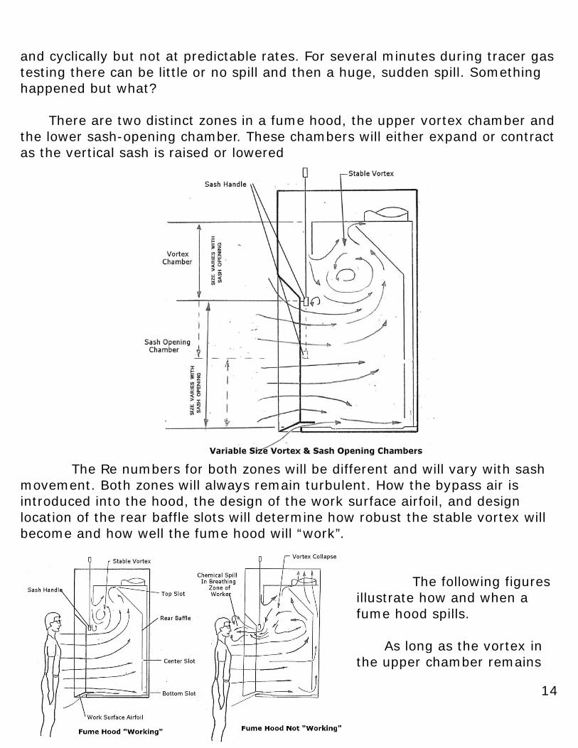
14
and cyclically but not at predictable rates. For several minutes during tracer gas testing there can be little or no spill and then a huge, sudden spill. Something happened but what? There are two distinct zones in a fume hood, the upper vortex chamber and the lower sash-opening chamber. These chambers will either expand or contract as the vertical sash is raised or lowered
The Re numbers for both zones will be different and will vary with sash movement. Both zones will always remain turbulent. How the bypass air is introduced into the hood, the design of the work surface airfoil, and design location of the rear baffle slots will determine how robust the stable vortex will become and how well the fume hood will “work”.
The following figures illustrate how and when a fume hood spills.
As long as the vortex in the upper chamber remains
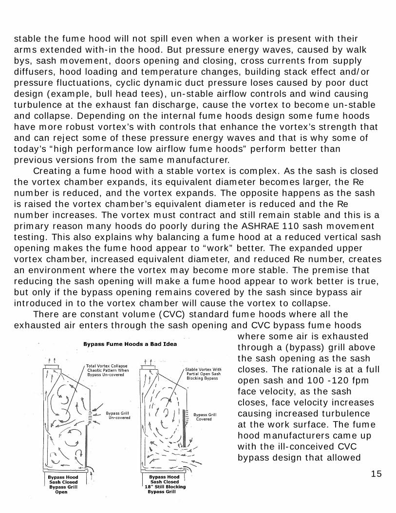
15
stable the fume hood will not spill even when a worker is present with their arms extended with-in the hood. But pressure energy waves, caused by walk bys, sash movement, doors opening and closing, cross currents from supply diffusers, hood loading and temperature changes, building stack effect and/or pressure fluctuations, cyclic dynamic duct pressure loses caused by poor duct design (example, bull head tees), un-stable airflow controls and wind causing turbulence at the exhaust fan discharge, cause the vortex to become un-stable and collapse. Depending on the internal fume hoods design some fume hoods have more robust vortex’s with controls that enhance the vortex’s strength that and can reject some of these pressure energy waves and that is why some of today’s “high performance low airflow fume hoods” perform better than previous versions from the same manufacturer. Creating a fume hood with a stable vortex is complex. As the sash is closed the vortex chamber expands, its equivalent diameter becomes larger, the Re number is reduced, and the vortex expands. The opposite happens as the sash is raised the vortex chamber’s equivalent diameter is reduced and the Re number increases. The vortex must contract and still remain stable and this is a primary reason many hoods do poorly during the ASHRAE 110 sash movement testing. This also explains why balancing a fume hood at a reduced vertical sash opening makes the fume hood appear to “work” better. The expanded upper vortex chamber, increased equivalent diameter, and reduced Re number, creates an environment where the vortex may become more stable. The premise that reducing the sash opening will make a fume hood appear to work better is true, but only if the bypass opening remains covered by the sash since bypass air introduced in to the vortex chamber will cause the vortex to collapse. There are constant volume (CVC) standard fume hoods where all the exhausted air enters through the sash opening and CVC bypass fume hoods
where some air is exhausted through a (bypass) grill above the sash opening as the sash closes. The rationale is at a full open sash and 100 -120 fpm face velocity, as the sash closes, face velocity increases causing increased turbulence at the work surface. The fume hood manufacturers came up with the ill-conceived CVC bypass design that allowed
16
some exhaust air to bypass the sash opening and enter in to the top vortex chamber of the hood, when the sash is lower than 18”. This attempted to maintain a uniform face velocity with sash closure, which proved to be a mistake. The bypass grill efficiency is around 60%/50% free open area versus the sash at almost 100% and the bypass grill represented a tortuous path for the airflow. What it did achieve was to produce face velocity anemometer pitch error readings that made it appear that the face velocity was more uniform. In fact, the only thing the bypass achieved was to make the fume hood internal vortex pattern complete chaos when the sash was lowered more than 18”and explains why the CVC bypass fume hood works so poorly during ASHRAE 110 tracer gas sash movement testing. This also explains why a well-designed variable air volume (VAV) controlled conventional hood without bypass performs better than a CVC bypass hood during sash movement tracer gas testing. The illustration shows the internal airflow patterns for a CVC bypass hood as the sash is lowered beyond an 18” opening and is the only reason why vertical sash stops are normally set at 18” height. There is nothing well designed about the 18” vertical stop and it does not protect the worker from splash or explosion and sash handle becomes a visual barrier for the less than average height worker. If the sash is lowered, the bypass will cause chaos within the vortex chamber and fume hood spillage. If the sash is raised higher than the Vortex chamber becomes smaller increasing the Re number and the vortex no longer remains stable. The 18” opening was “backed into” by the fact it was the only opening that appeared to “work” and the IH later claimed reduced 18” sash opening is for splash and explosion protection. This is a FALSE deduction!
17
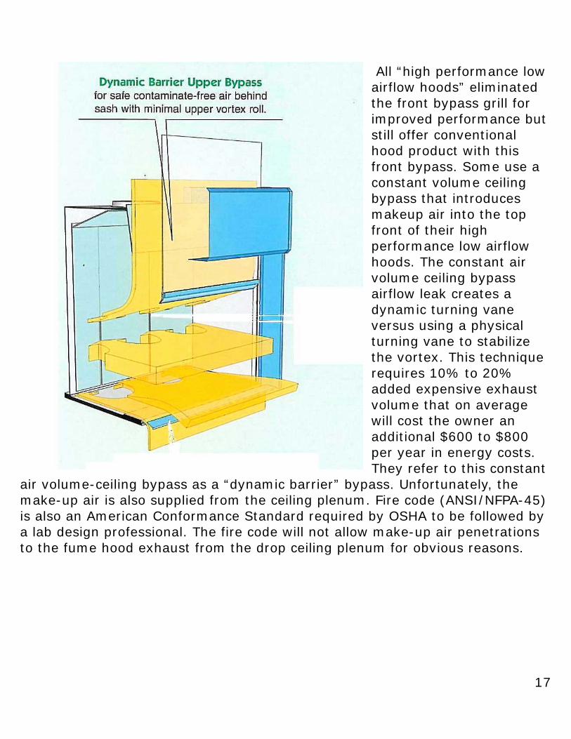
All “high performance low airflow hoods” eliminated the front bypass grill for improved performance but still offer conventional hood product with this front bypass. Some use a constant volume ceiling bypass that introduces makeup air into the top front of their high performance low airflow hoods. The constant air volume ceiling bypass airflow leak creates a dynamic turning vane versus using a physical turning vane to stabilize the vortex. This technique requires 10% to 20% added expensive exhaust volume that on average will cost the owner an additional $600 to $800 per year in energy costs. They refer to this constant
air volume-ceiling bypass as a “dynamic barrier” bypass. Unfortunately, the make-up air is also supplied from the ceiling plenum. Fire code (ANSI/NFPA-45) is also an American Conformance Standard required by OSHA to be followed by a lab design professional. The fire code will not allow make-up air penetrations to the fume hood exhaust from the drop ceiling plenum for obvious reasons.
18
How to Control the Vortex If a fume hood testing certified technologist (CT) or PE is requested to test any fume hood without some properly designed rear baffle, the fume hood automatically fails and it has to be taken out of service. Adjustable rear baffle slots are not new. Fume hood manufactures sold the adjustable rear baffle slots to accommodate changes in density or heat of the experiment and the IH taught they were adjusted to achieve face velocity uniformity but both were wrong. The way the fume hood industry explained the baffle slot adjustment is that you open the bottom baffle slot for “heavier than air” gases and the top baffle slot is opened for hot temperature experiments. Their theory was based on the laminar fume design/model, which we have shown before to be false. Fume hoods are turbulent with all fumes and vapors completely distributed throughout when the vortex collapses but when the vortex is stable the fumes are evenly distributed throughout the hood, except within the stable vortex. The greater the vortex stability the fewer chemical fumes enter into the vortex. The more stable the vortex, the more robust and resistant the fume hood is to energy pressure waves and environmental challenges. When the fume hood experiment runs “hot” it will increase the Re number making the fume hoods vortex chamber more turbulent. One of the major errors using large volume smoke testing is it cannot differentiate between airflow patterns and where the harmful chemical vapors concentrations actually appear within a fume hood. Using smoke to empirically develop a fume hood is perhaps the worst method possible but this technique is what all fume hood designers used until Computational Fluid Dynamics (CFD) modeling became affordable in the 1990’s. CFD is a computer technique that dices a domain such as a laboratory space with or without a fume hood (or even a lab-building roof exhaust system)
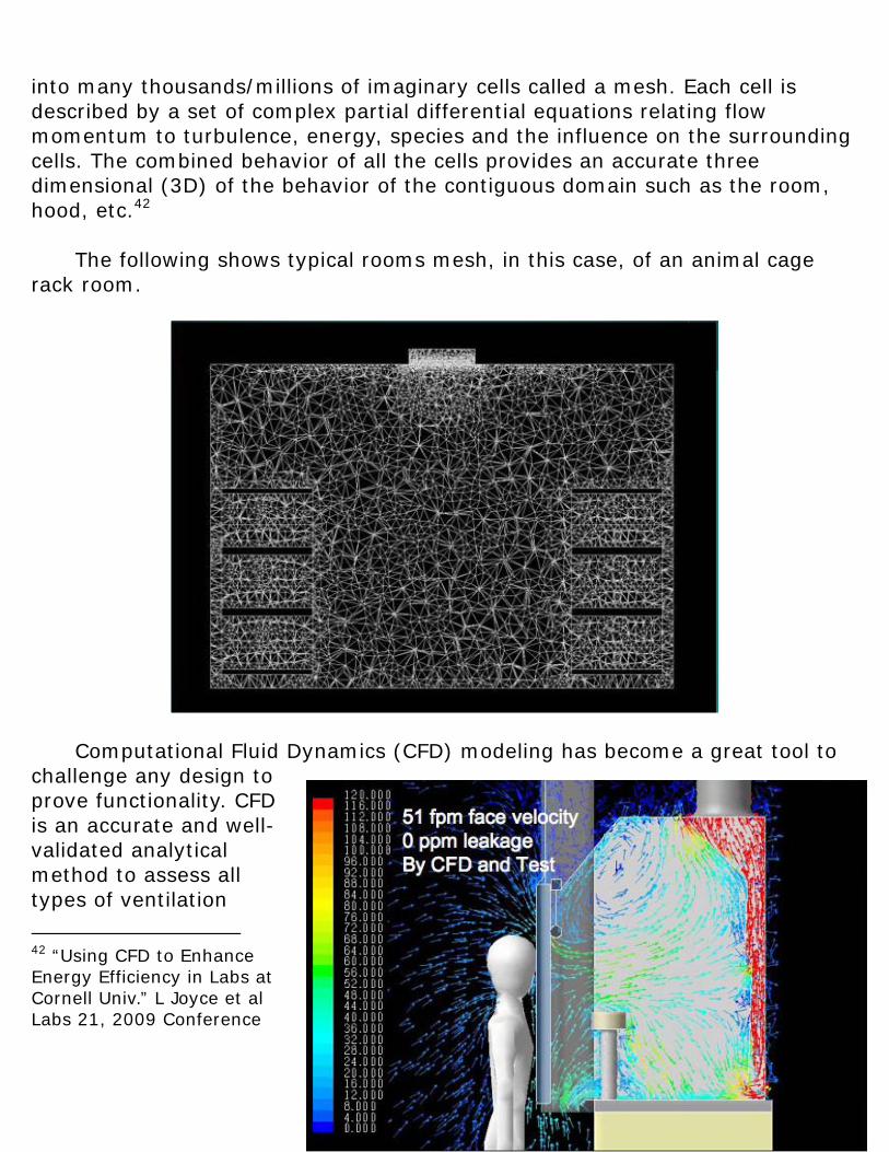
19
into many thousands/millions of imaginary cells called a mesh. Each cell is described by a set of complex partial differential equations relating flow momentum to turbulence, energy, species and the influence on the surrounding cells. The combined behavior of all the cells provides an accurate three dimensional (3D) of the behavior of the contiguous domain such as the room, hood, etc.42 The following shows typical rooms mesh, in this case, of an animal cage rack room.
Computational Fluid Dynamics (CFD) modeling has become a great tool to challenge any design to prove functionality. CFD is an accurate and well-validated analytical method to assess all types of ventilation
42 “Using CFD to Enhance Energy Efficiency in Labs at Cornell Univ.” L Joyce et al Labs 21, 2009 Conference
20
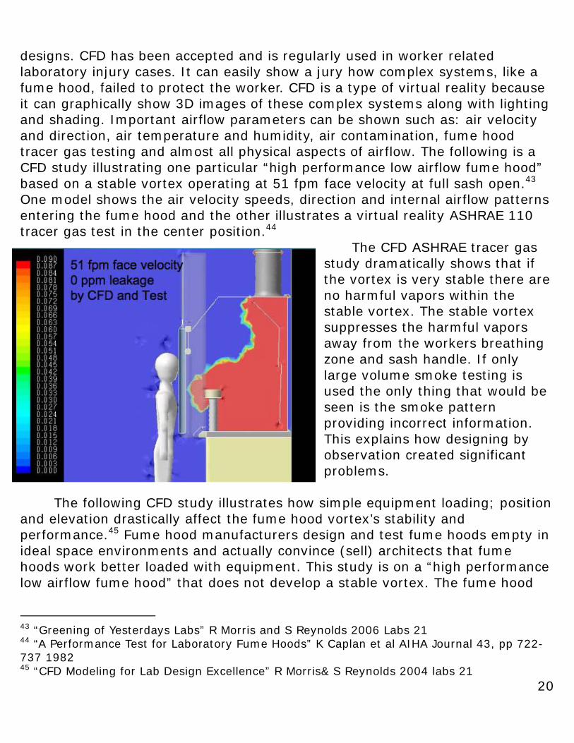
designs. CFD has been accepted and is regularly used in worker related laboratory injury cases. It can easily show a jury how complex systems, like a fume hood, failed to protect the worker. CFD is a type of virtual reality because it can graphically show 3D images of these complex systems along with lighting and shading. Important airflow parameters can be shown such as: air velocity and direction, air temperature and humidity, air contamination, fume hood tracer gas testing and almost all physical aspects of airflow. The following is a CFD study illustrating one particular “high performance low airflow fume hood” based on a stable vortex operating at 51 fpm face velocity at full sash open.43 One model shows the air velocity speeds, direction and internal airflow patterns entering the fume hood and the other illustrates a virtual reality ASHRAE 110 tracer gas test in the center position.44
The CFD ASHRAE tracer gas study dramatically shows that if the vortex is very stable there are no harmful vapors within the stable vortex. The stable vortex suppresses the harmful vapors away from the workers breathing zone and sash handle. If only large volume smoke testing is used the only thing that would be seen is the smoke pattern providing incorrect information. This explains how designing by observation created significant problems.
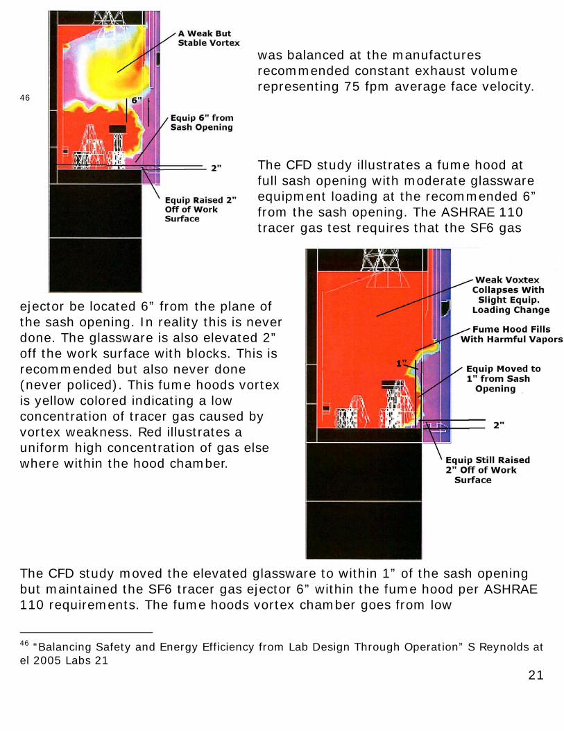
The following CFD study illustrates how simple equipment loading; position and elevation drastically affect the fume hood vortex’s stability and performance.45 Fume hood manufacturers design and test fume hoods empty in ideal space environments and actually convince (sell) architects that fume hoods work better loaded with equipment. This study is on a “high performance low airflow fume hood” that does not develop a stable vortex. The fume hood
43 “Greening of Yesterdays Labs” R Morris and S Reynolds 2006 Labs 21 44 “A Performance Test for Laboratory Fume Hoods” K Caplan et al AIHA Journal 43, pp 722-737 1982 45 “CFD Modeling for Lab Design Excellence” R Morris& S Reynolds 2004 labs 21
21
was balanced at the manufactures recommended constant exhaust volume representing 75 fpm average face velocity.
46
The CFD study illustrates a fume hood at full sash opening with moderate glassware equipment loading at the recommended 6” from the sash opening. The ASHRAE 110 tracer gas test requires that the SF6 gas
ejector be located 6” from the plane of the sash opening. In reality this is never done. The glassware is also elevated 2” off the work surface with blocks. This is recommended but also never done (never policed). This fume hoods vortex is yellow colored indicating a low concentration of tracer gas caused by vortex weakness. Red illustrates a uniform high concentration of gas else where within the hood chamber. The CFD study moved the elevated glassware to within 1” of the sash opening but maintained the SF6 tracer gas ejector 6” within the fume hood per ASHRAE 110 requirements. The fume hoods vortex chamber goes from low
46 “Balancing Safety and Energy Efficiency from Lab Design Through Operation” S Reynolds at el 2005 Labs 21
22
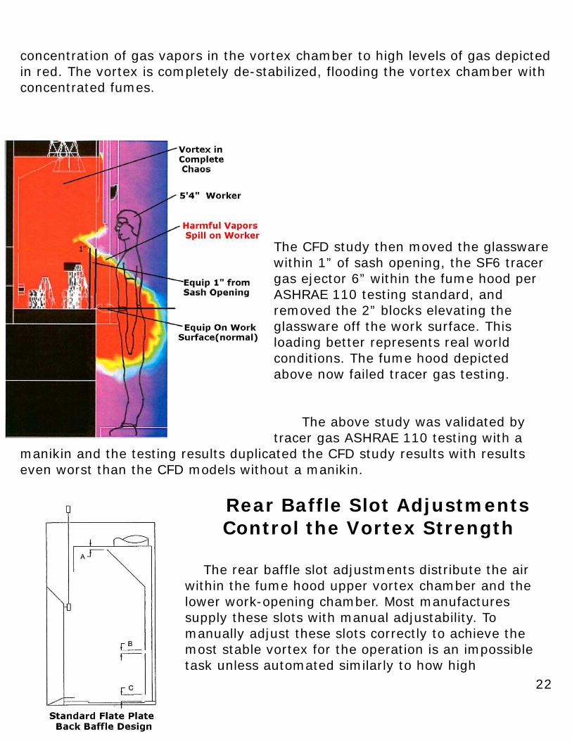
concentration of gas vapors in the vortex chamber to high levels of gas depicted in red. The vortex is completely de-stabilized, flooding the vortex chamber with concentrated fumes.
The CFD study then moved the glassware within 1” of sash opening, the SF6 tracer gas ejector 6” within the fume hood per ASHRAE 110 testing standard, and removed the 2” blocks elevating the glassware off the work surface. This loading better represents real world conditions. The fume hood depicted above now failed tracer gas testing. The above study was validated by tracer gas ASHRAE 110 testing with a
manikin and the testing results duplicated the CFD study results with results even worst than the CFD models without a manikin.
Rear Baffle Slot Adjustments Control the Vortex Strength
The rear baffle slot adjustments distribute the air within the fume hood upper vortex chamber and the lower work-opening chamber. Most manufactures supply these slots with manual adjustability. To manually adjust these slots correctly to achieve the most stable vortex for the operation is an impossible task unless automated similarly to how high
23
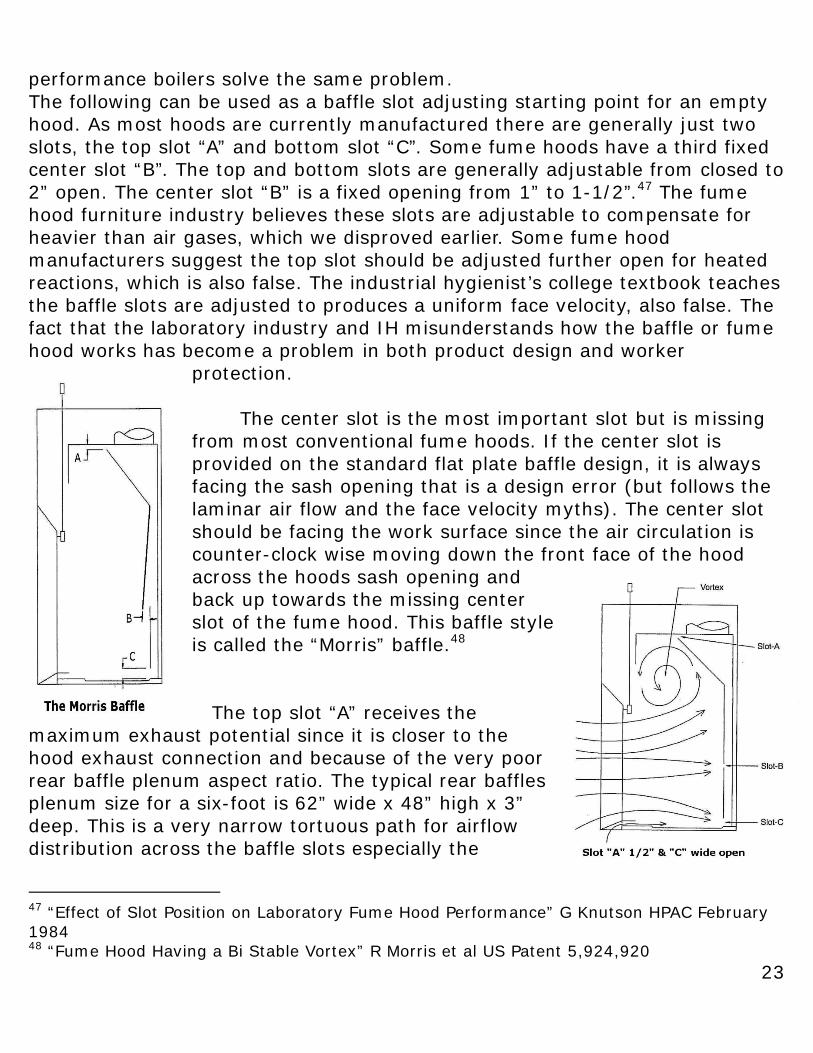
performance boilers solve the same problem. The following can be used as a baffle slot adjusting starting point for an empty hood. As most hoods are currently manufactured there are generally just two slots, the top slot “A” and bottom slot “C”. Some fume hoods have a third fixed center slot “B”. The top and bottom slots are generally adjustable from closed to 2” open. The center slot “B” is a fixed opening from 1” to 1-1/2”.47 The fume hood furniture industry believes these slots are adjustable to compensate for heavier than air gases, which we disproved earlier. Some fume hood manufacturers suggest the top slot should be adjusted further open for heated reactions, which is also false. The industrial hygienist’s college textbook teaches the baffle slots are adjusted to produces a uniform face velocity, also false. The fact that the laboratory industry and IH misunderstands how the baffle or fume hood works has become a problem in both product design and worker
protection.
The center slot is the most important slot but is missing from most conventional fume hoods. If the center slot is provided on the standard flat plate baffle design, it is always facing the sash opening that is a design error (but follows the laminar air flow and the face velocity myths). The center slot should be facing the work surface since the air circulation is counter-clock wise moving down the front face of the hood across the hoods sash opening and back up towards the missing center slot of the fume hood. This baffle style is called the “Morris” baffle.48
The top slot “A” receives the maximum exhaust potential since it is closer to the hood exhaust connection and because of the very poor rear baffle plenum aspect ratio. The typical rear baffles plenum size for a six-foot is 62” wide x 48” high x 3” deep. This is a very narrow tortuous path for airflow distribution across the baffle slots especially the
47 “Effect of Slot Position on Laboratory Fume Hood Performance” G Knutson HPAC February 1984 48 “Fume Hood Having a Bi Stable Vortex” R Morris et al US Patent 5,924,920
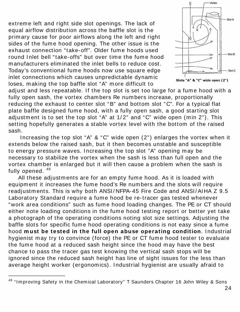
24
extreme left and right side slot openings. The lack of equal airflow distribution across the baffle slot is the primary cause for poor airflows along the left and right sides of the fume hood opening. The other issue is the exhaust connection “take-off”. Older fume hoods used round Inlet bell “take-offs” but over time the fume hood manufacturers eliminated the inlet bells to reduce cost. Today’s conventional fume hoods now use square edge inlet connections which causes unpredictable dynamic loses, making the top baffle slot “A” more difficult to adjust and less repeatable. If the top slot is set too large for a fume hood with a fully open sash, the vortex chambers Re numbers increase, proportionally reducing the exhaust to center slot “B” and bottom slot ”C”. For a typical flat plate baffle designed fume hood, with a fully open sash, a good starting slot adjustment is to set the top slot “A” at 1/2” and “C” wide open (min 2”). This setting hopefully generates a stable vortex level with the bottom of the raised sash. Increasing the top slot “A” & “C” wide open (2”) enlarges the vortex when it extends below the raised sash, but it then becomes unstable and susceptible to energy pressure waves. Increasing the top slot ”A” opening may be necessary to stabilize the vortex when the sash is less than full open and the vortex chamber is enlarged but it will then cause a problem when the sash is fully opened. 49 All these adjustments are for an empty fume hood. As it is loaded with equipment it increases the fume hood’s Re numbers and the slots will require readjustments. This is why both ANSI/NFPA-45 Fire Code and ANSI/AIHA Z 9.5 Laboratory Standard require a fume hood be re-tracer gas tested whenever “work area conditions” such as fume hood loading changes. The PE or CT should either note loading conditions in the fume hood testing report or better yet take a photograph of the operating conditions noting slot size settings. Adjusting the baffle slots for specific fume hood operating conditions is not easy since a fume hood must be tested in the full open abuse operating condition. Industrial hygienist may try to convince (force) the PE or CT fume hood tester to evaluate the fume hood at a reduced sash height since the hood may have the best chance to pass the tracer gas test knowing the vertical sash stops will be ignored since the reduced sash height has line of sight issues for the less than average height worker (ergonomics). Industrial hygienist are usually afraid to
49 “Improving Safety in the Chemical Laboratory” T Saunders Chapter 16 John Wiley & Sons
25
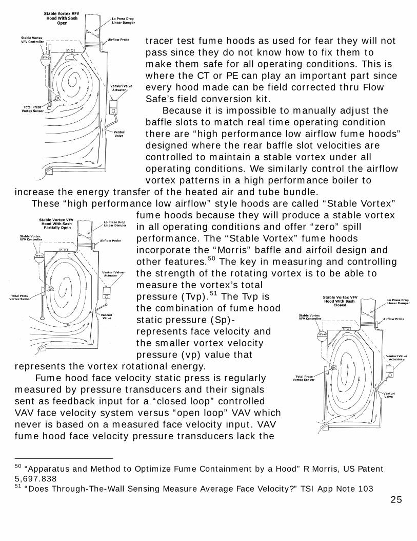
tracer test fume hoods as used for fear they will not pass since they do not know how to fix them to make them safe for all operating conditions. This is where the CT or PE can play an important part since every hood made can be field corrected thru Flow Safe’s field conversion kit. Because it is impossible to manually adjust the baffle slots to match real time operating condition there are “high performance low airflow fume hoods” designed where the rear baffle slot velocities are controlled to maintain a stable vortex under all operating conditions. We similarly control the airflow vortex patterns in a high performance boiler to
increase the energy transfer of the heated air and tube bundle. These “high performance low airflow” style hoods are called “Stable Vortex”
fume hoods because they will produce a stable vortex in all operating conditions and offer “zero” spill performance. The “Stable Vortex” fume hoods incorporate the “Morris” baffle and airfoil design and other features.50 The key in measuring and controlling the strength of the rotating vortex is to be able to measure the vortex’s total pressure (Tvp).51 The Tvp is the combination of fume hood static pressure (Sp)-represents face velocity and the smaller vortex velocity pressure (vp) value that
represents the vortex rotational energy. Fume hood face velocity static press is regularly measured by pressure transducers and their signals sent as feedback input for a “closed loop” controlled VAV face velocity system versus “open loop” VAV which never is based on a measured face velocity input. VAV fume hood face velocity pressure transducers lack the
50 “Apparatus and Method to Optimize Fume Containment by a Hood” R Morris, US Patent 5,697.838 51 “Does Through-The-Wall Sensing Measure Average Face Velocity?” TSI App Note 103
26
resolution to measure the vortex rotational pressure that appears to VAV pressure transducer as background noise. The stable vortex fume hoods incorporating auto adjusting baffle slot velocity controls are called VFV fume hood controlled systems. These stable vortex constant exhaust volume fume hood’s face velocity varies with variance in sash openings. The total vortex pressure transducer senses a change in the vortex’s rotational strength, which will be effected by hood loading, temperature, cross currents and sash movements. These all affect the fume hoods ever changing Re number and the VFV fume hood automatically re-adjusts the slot velocities by modulating a baffle plenum venturi valve redirecting the exhaust air to different slots to maintain a stable vortex operating within the fume hoods effective Re number. If fume hoods fail ASHRAE 110 tracer gas testing and or do not meet OSHA vapor, splash and explosion worker protection requirement, there are Flow Safe conversion kits available that incorporate VFV baffle control to convert existing fume hoods into “high performance low airflow” stable vortex hoods. These fume hood conversion kits replace the rear baffle, correct the work surface airfoil design, upgrade the sash to meet ANSI/NFPA 45 fire code splash & explosion.
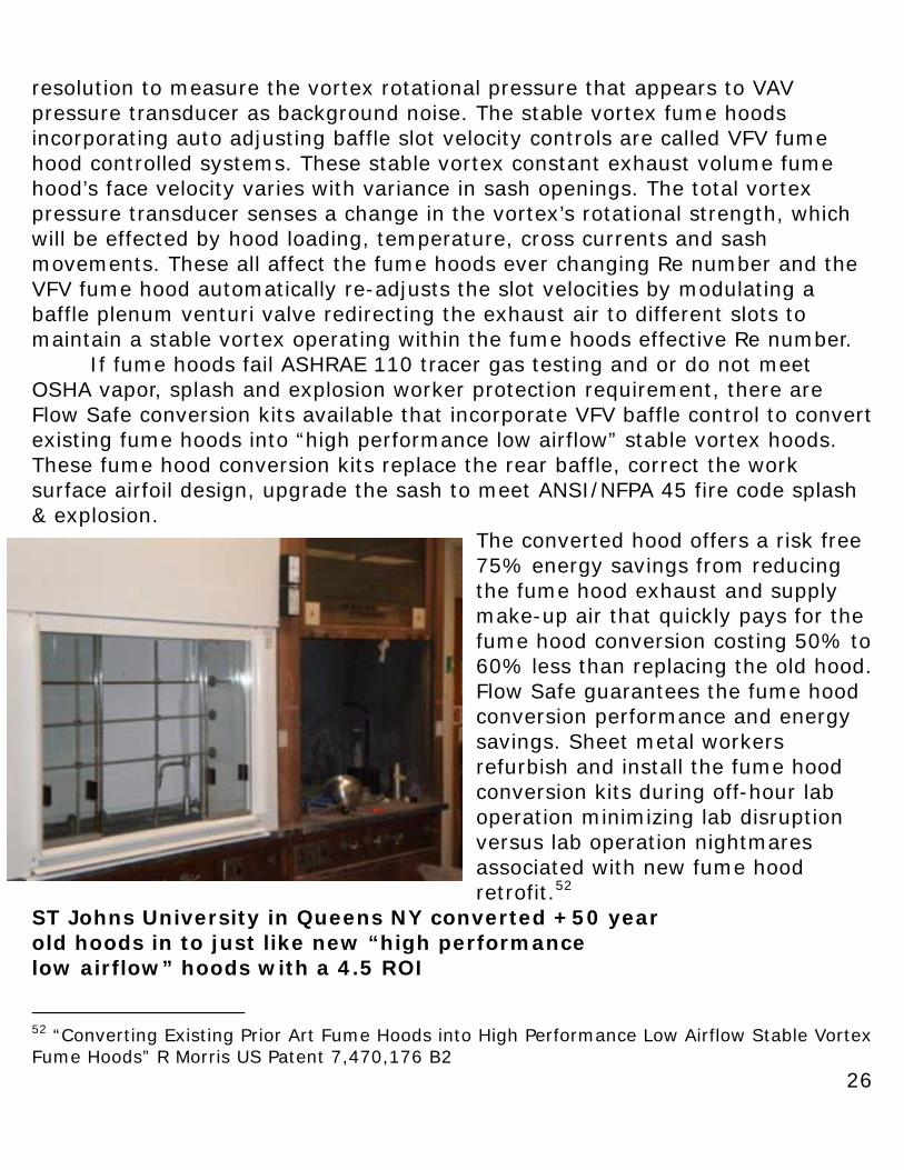
The converted hood offers a risk free 75% energy savings from reducing the fume hood exhaust and supply make-up air that quickly pays for the fume hood conversion costing 50% to 60% less than replacing the old hood. Flow Safe guarantees the fume hood conversion performance and energy savings. Sheet metal workers refurbish and install the fume hood conversion kits during off-hour lab operation minimizing lab disruption versus lab operation nightmares associated with new fume hood retrofit.52
ST Johns University in Queens NY converted +50 year old hoods in to just like new “high performance low airflow” hoods with a 4.5 ROI
52 “Converting Existing Prior Art Fume Hoods into High Performance Low Airflow Stable Vortex Fume Hoods” R Morris US Patent 7,470,176 B2
27
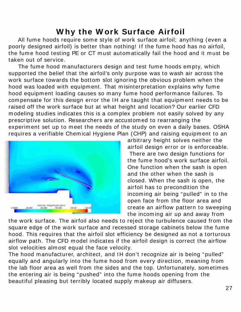
Why the Work Surface Airfoil All fume hoods require some style of work surface airfoil; anything (even a poorly designed airfoil) is better than nothing! If the fume hood has no airfoil, the fume hood testing PE or CT must automatically fail the hood and it must be taken out of service. The fume hood manufacturers design and test fume hoods empty, which supported the belief that the airfoil’s only purpose was to wash air across the work surface towards the bottom slot ignoring the obvious problem when the hood was loaded with equipment. That misinterpretation explains why fume hood equipment loading causes so many fume hood performance failures. To compensate for this design error the IH are taught that equipment needs to be raised off the work surface but at what height and location? Our earlier CFD modeling studies indicates this is a complex problem not easily solved by any prescriptive solution. Researchers are accustomed to rearranging the experiment set up to meet the needs of the study on even a daily bases. OSHA requires a verifiable Chemical Hygiene Plan (CHP) and raising equipment to an
arbitrary height solves neither the airfoil design error or is enforceable. There are two design functions for the fume hood’s work surface airfoil. One function when the sash is open and the other when the sash is closed. When the sash is open, the airfoil has to precondition the incoming air being “pulled” in to the open face from the floor area and create an airflow pattern to sweeping the incoming air up and away from
the work surface. The airfoil also needs to reject the turbulence caused from the square edge of the work surface and recessed storage cabinets below the fume hood. This requires that the airfoil slot efficiency be designed as not a torturous airflow path. The CFD model indicates if the airfoil design is correct the airflow slot velocities almost equal the face velocity. The hood manufacturer, architect, and IH don’t recognize air is being “pulled” equally and angularly into the fume hood from every direction, meaning from the lab floor area as well from the sides and the top. Unfortunately, sometimes the entering air is being “pushed” into the fume hoods opening from the beautiful pleasing but terribly located supply makeup air diffusers.
28
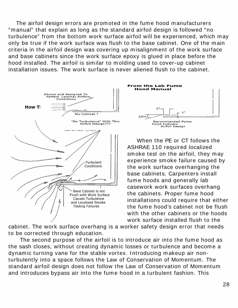
The airfoil design errors are promoted in the fume hood manufacturers “manual” that explain as long as the standard airfoil design is followed “no turbulence” from the bottom work surface airfoil will be experienced, which may only be true if the work surface was flush to the base cabinet. One of the main criteria in the airfoil design was covering up misalignment of the work surface and base cabinets since the work surface epoxy is glued in place before the hood installed. The airfoil is similar to molding used to cover-up cabinet installation issues. The work surface is never aliened flush to the cabinet.
When the PE or CT follows the ASHRAE 110 required localized smoke test on the airfoil, they may experience smoke failure caused by the work surface overhanging the base cabinets. Carpenters install fume hoods and generally lab casework work surfaces overhang the cabinets. Proper fume hood installations could require that either the fume hood’s cabinet not be flush with the other cabinets or the hoods work surface installed flush to the
cabinet. The work surface overhang is a worker safety design error that needs to be corrected through education. The second purpose of the airfoil is to introduce air into the fume hood as the sash closes, without creating dynamic losses or turbulence and become a dynamic turning vane for the stable vortex. Introducing makeup air non-turbulently into a space follows the Law of Conservation of Momentum. The standard airfoil design does not follow the Law of Conservation of Momentum and introduces bypass air into the fume hood in a turbulent fashion. This
29
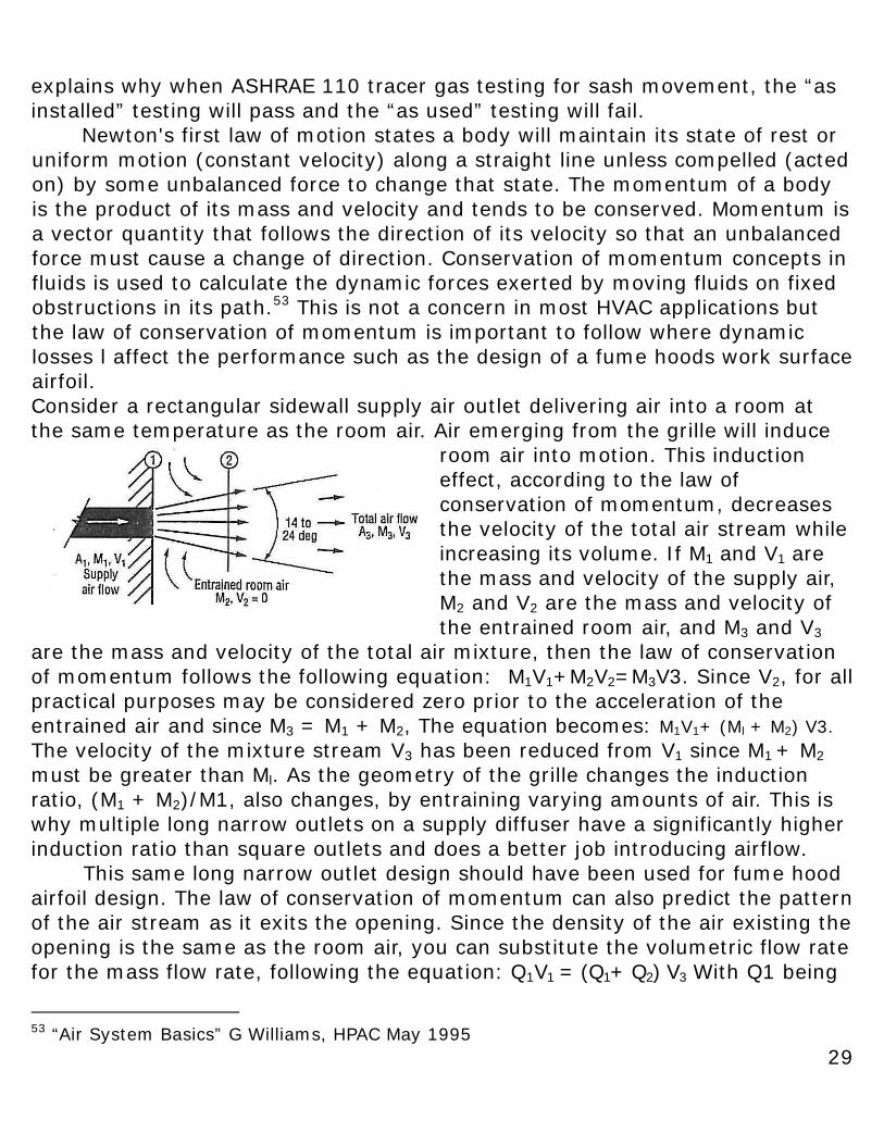
explains why when ASHRAE 110 tracer gas testing for sash movement, the “as installed” testing will pass and the “as used” testing will fail. Newton's first law of motion states a body will maintain its state of rest or uniform motion (constant velocity) along a straight line unless compelled (acted on) by some unbalanced force to change that state. The momentum of a body is the product of its mass and velocity and tends to be conserved. Momentum is a vector quantity that follows the direction of its velocity so that an unbalanced force must cause a change of direction. Conservation of momentum concepts in fluids is used to calculate the dynamic forces exerted by moving fluids on fixed obstructions in its path.53 This is not a concern in most HVAC applications but the law of conservation of momentum is important to follow where dynamic losses l affect the performance such as the design of a fume hoods work surface airfoil. Consider a rectangular sidewall supply air outlet delivering air into a room at the same temperature as the room air. Air emerging from the grille will induce
room air into motion. This induction effect, according to the law of conservation of momentum, decreases the velocity of the total air stream while increasing its volume. If M1 and V1 are the mass and velocity of the supply air, M2 and V2 are the mass and velocity of the entrained room air, and M3 and V3
are the mass and velocity of the total air mixture, then the law of conservation of momentum follows the following equation: M1V1+M2V2=M3V3. Since V2, for all practical purposes may be considered zero prior to the acceleration of the entrained air and since M3 = M1 + M2, The equation becomes: M1V1+ (Ml + M2) V3. The velocity of the mixture stream V3 has been reduced from V1 since M1 + M2 must be greater than Ml. As the geometry of the grille changes the induction ratio, (M1 + M2)/M1, also changes, by entraining varying amounts of air. This is why multiple long narrow outlets on a supply diffuser have a significantly higher induction ratio than square outlets and does a better job introducing airflow.
This same long narrow outlet design should have been used for fume hood airfoil design. The law of conservation of momentum can also predict the pattern of the air stream as it exits the opening. Since the density of the air existing the opening is the same as the room air, you can substitute the volumetric flow rate for the mass flow rate, following the equation: Q1V1 = (Q1+ Q2) V3 With Q1 being
53 “Air System Basics” G Williams, HPAC May 1995
30
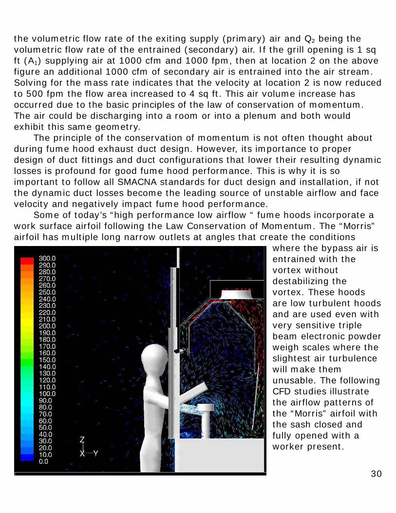
the volumetric flow rate of the exiting supply (primary) air and Q2 being the volumetric flow rate of the entrained (secondary) air. If the grill opening is 1 sq ft (A1) supplying air at 1000 cfm and 1000 fpm, then at location 2 on the above figure an additional 1000 cfm of secondary air is entrained into the air stream. Solving for the mass rate indicates that the velocity at location 2 is now reduced to 500 fpm the flow area increased to 4 sq ft. This air volume increase has occurred due to the basic principles of the law of conservation of momentum. The air could be discharging into a room or into a plenum and both would exhibit this same geometry. The principle of the conservation of momentum is not often thought about during fume hood exhaust duct design. However, its importance to proper design of duct fittings and duct configurations that lower their resulting dynamic losses is profound for good fume hood performance. This is why it is so important to follow all SMACNA standards for duct design and installation, if not the dynamic duct losses become the leading source of unstable airflow and face velocity and negatively impact fume hood performance. Some of today’s “high performance low airflow “ fume hoods incorporate a work surface airfoil following the Law Conservation of Momentum. The “Morris” airfoil has multiple long narrow outlets at angles that create the conditions
where the bypass air is entrained with the vortex without destabilizing the vortex. These hoods are low turbulent hoods and are used even with very sensitive triple beam electronic powder weigh scales where the slightest air turbulence will make them unusable. The following CFD studies illustrate the airflow patterns of the “Morris” airfoil with the sash closed and fully opened with a worker present.
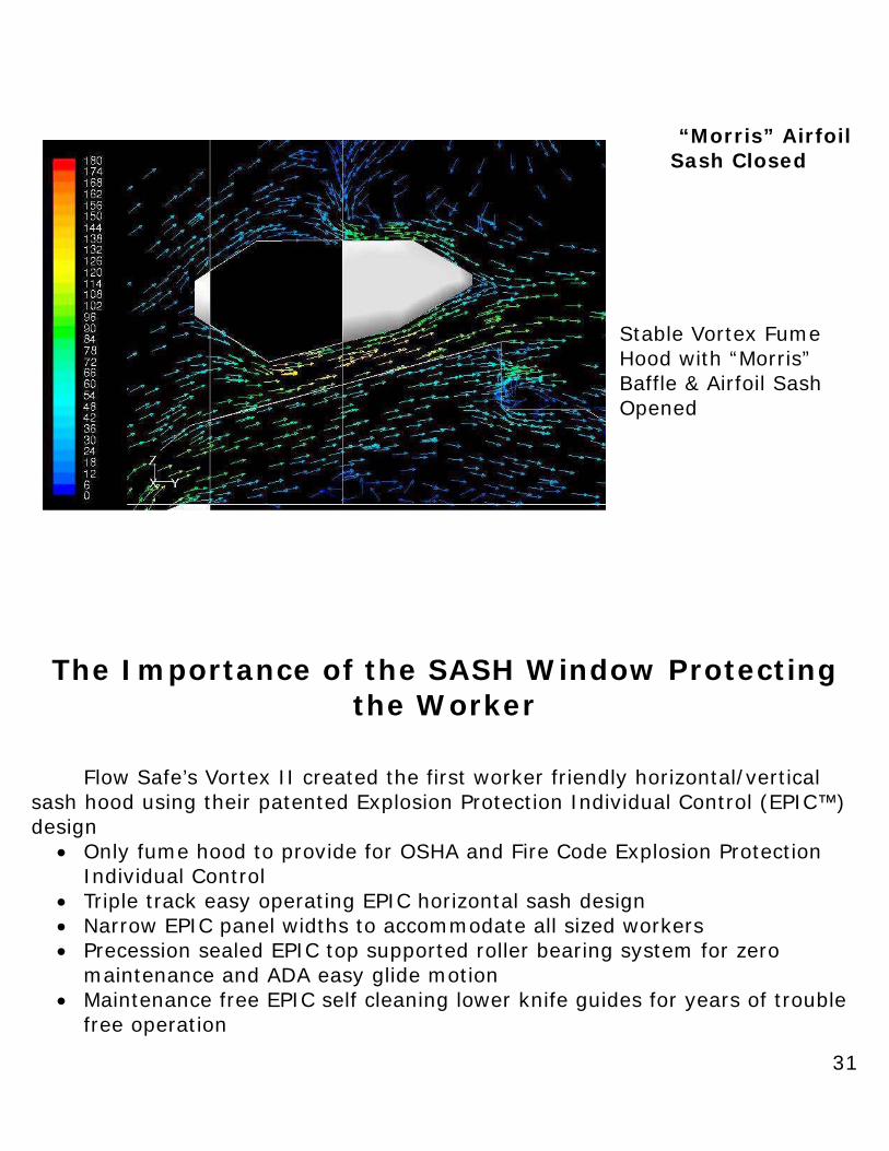
31
“Morris” Airfoil Sash Closed
Stable Vortex Fume Hood with “Morris” Baffle & Airfoil Sash Opened
The Importance of the SASH Window Protecting the Worker
Flow Safe’s Vortex II created the first worker friendly horizontal/vertical sash hood using their patented Explosion Protection Individual Control (EPIC™) design
• Only fume hood to provide for OSHA and Fire Code Explosion Protection Individual Control
• Triple track easy operating EPIC horizontal sash design • Narrow EPIC panel widths to accommodate all sized workers • Precession sealed EPIC top supported roller bearing system for zero
maintenance and ADA easy glide motion • Maintenance free EPIC self cleaning lower knife guides for years of trouble
free operation
32
• EPIC hazardous vapor protection for all height workers • 20% greater vertical opening with an EPIC polycarbonate face guard for
added worker protection • Full vertical for test set-up • A generous full vertical opening for the applications when splash and
explosion protection is not required The Issue
For years fume hood safety was considered only for chemical vapor worker protection using face velocity as the test for vapor worker safety protection from hazardous chemicals. Fume hood face velocity should have become obsolete when the Federal OSHA Laboratory Worker Law was passed by Congress in 1990 and replaced with routine performance monitoring for hazardous chemicals. Unfortunately AIHA with the assumed responsibility responsible to educate the IH, lab workers, and employers on lab safety recently told Congress they were biased against the OSHA Law as one of the reasons they failed their responsibility.
The 1990 OSHA Law required that a fume hood protect the worker from vapor, splash, and explosion not just vapor. Fume hood performance now requires routine personal sample performance monitoring for hazardous chemicals. If the worker was exposed from vapor, splash or explosion than an OSHA emergency existed, the exposed worker notified, and the worker was sent for medical evaluation. It is rarely known to be reported despite the obvious concern to employee safety/health. The Problem
The conventional bypass hood with vertical sash window does not protect the worker from splash/explosion per fire code and standards as required by OSHA. The commonly used portable weighted shield used with a conventional hood for explosion protection, according to fire code, becomes a secondary missile in an explosion. A conventional fume hood even fails to protect less than average height workers from hazardous vapor exposure, another Federal law violation. Most laboratories Chemical Hygiene Plan fails to address any of these issues putting employers, primary investigators, and lab owners at considerable risk.545556 54 “Quantitative Fume Hood Evaluation for Operator Safety” J Wunder Chemical Health & Safety July/ August 2000 55 “Laboratory Fume Hoods” National Safety Council” Data Sheet 1-687-80 56 “The Effects of Thermal Loading on Laboratory Fume Hoods Performance” J Johnston et al Applied Occupational & Environmental Hygiene Volume 15 2000
33
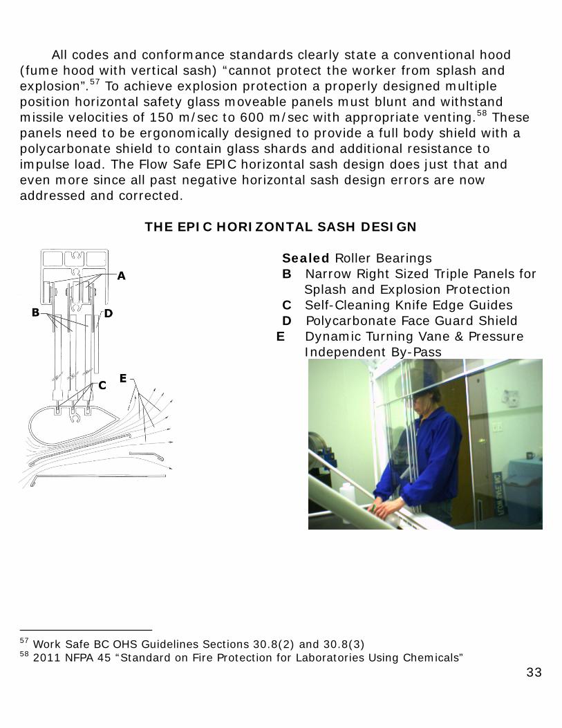
All codes and conformance standards clearly state a conventional hood (fume hood with vertical sash) “cannot protect the worker from splash and explosion”.57 To achieve explosion protection a properly designed multiple position horizontal safety glass moveable panels must blunt and withstand missile velocities of 150 m/sec to 600 m/sec with appropriate venting.58 These panels need to be ergonomically designed to provide a full body shield with a polycarbonate shield to contain glass shards and additional resistance to impulse load. The Flow Safe EPIC horizontal sash design does just that and even more since all past negative horizontal sash design errors are now addressed and corrected.
THE EPIC HORIZONTAL SASH DESIGN Sealed Roller Bearings B Narrow Right Sized Triple Panels for Splash and Explosion Protection C Self-Cleaning Knife Edge Guides D Polycarbonate Face Guard Shield
E Dynamic Turning Vane & Pressure Independent By-Pass
57 Work Safe BC OHS Guidelines Sections 30.8(2) and 30.8(3) 58 2011 NFPA 45 “Standard on Fire Protection for Laboratories Using Chemicals”
34
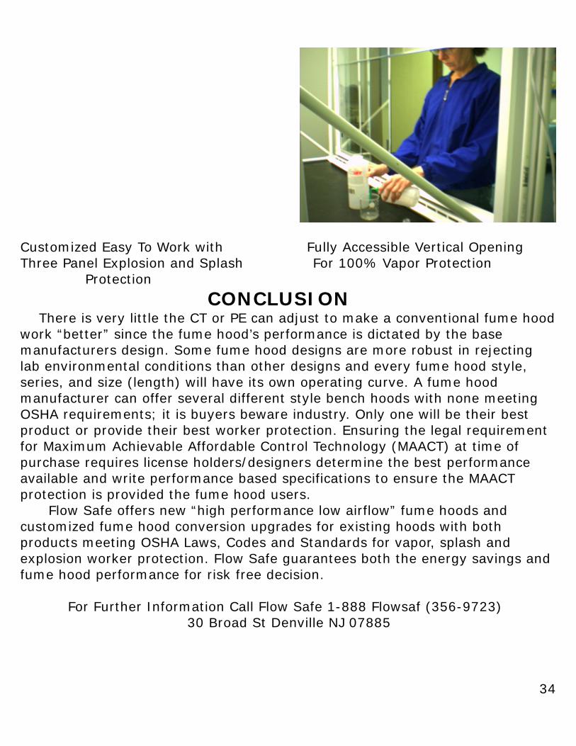
Customized Easy To Work with Fully Accessible Vertical Opening Three Panel Explosion and Splash For 100% Vapor Protection Protection
CONCLUSION There is very little the CT or PE can adjust to make a conventional fume hood work “better” since the fume hood’s performance is dictated by the base manufacturers design. Some fume hood designs are more robust in rejecting lab environmental conditions than other designs and every fume hood style, series, and size (length) will have its own operating curve. A fume hood manufacturer can offer several different style bench hoods with none meeting OSHA requirements; it is buyers beware industry. Only one will be their best product or provide their best worker protection. Ensuring the legal requirement for Maximum Achievable Affordable Control Technology (MAACT) at time of purchase requires license holders/designers determine the best performance available and write performance based specifications to ensure the MAACT protection is provided the fume hood users. Flow Safe offers new “high performance low airflow” fume hoods and customized fume hood conversion upgrades for existing hoods with both products meeting OSHA Laws, Codes and Standards for vapor, splash and explosion worker protection. Flow Safe guarantees both the energy savings and fume hood performance for risk free decision. For Further Information Call Flow Safe 1-888 Flowsaf (356-9723) 30 Broad St Denville NJ 07885