Embed Size (px)
Citation preview
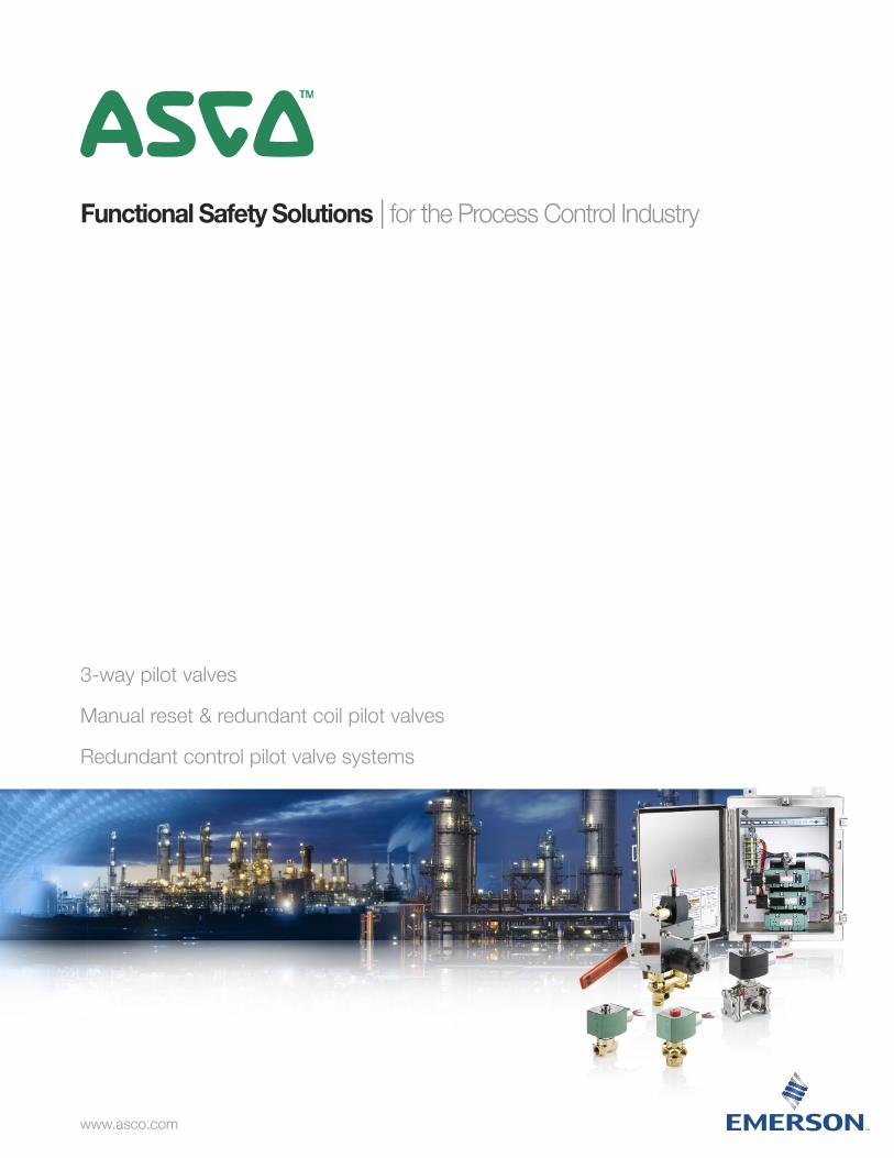
Functional Safety Solutions | for the Process Control Industry
3-way pilot valves
Manual reset & redundant coil pilot valves
Redundant control pilot valve systems
www.asco.com
1
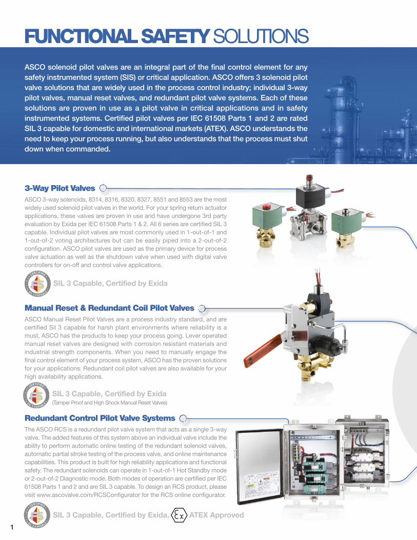
ASCO solenoid pilot valves are an integral part of the final control element for anysafety instrumented system (SIS) or critical application. ASCO offers 3 solenoid pilotvalve solutions that are widely used in the process control industry; individual 3-waypilot valves, manual reset valves, and redundant pilot valve systems. Each of thesesolutions are proven in use as a pilot valve in critical applications and in safety instrumented systems. Certified pilot valves per IEC 61508 Parts 1 and 2 are rated SIL 3 capable for domestic and international markets (ATEX). ASCO understands theneed to keep your process running, but also understands that the process must shutdown when commanded.
3-Way Pilot ValvesASCO 3-way solenoids, 8314, 8316, 8320, 8327, 8551 and 8553 are the mostwidely used solenoid pilot valves in the world. For your spring return actuatorapplications, these valves are proven in use and have undergone 3rd partyevaluation by Exida per IEC 61508 Parts 1 & 2. All 6 series are certified SIL 3capable. Individual pilot valves are most commonly used in 1-out-of-1 and1-out-of-2 voting architectures but can be easily piped into a 2-out-of-2configuration. ASCO pilot valves are used as the primary device for processvalve actuation as well as the shutdown valve when used with digital valvecontrollers for on-off and control valve applications.
Redundant Control Pilot Valve SystemsThe ASCO RCS is a redundant pilot valve system that acts as a single 3-wayvalve. The added features of this system above an individual valve include theability to perform automatic online testing of the redundant solenoid valves,automatic partial stroke testing of the process valve, and online maintenancecapabilities. This product is built for high reliability applications and functionalsafety. The redundant solenoids can operate in 1-out-of-1 Hot Standby modeor 2-out-of-2 Diagnostic mode. Both modes of operation are certified per IEC61508 Parts 1 and 2 and are SIL 3 capable. To design an RCS product, pleasevisit www.ascovalve.com/RCSConfigurator for the RCS online configurator.
Manual Reset & Redundant Coil Pilot ValvesASCO Manual Reset Pilot Valves are a process industry standard, and arecertified Sil 3 capable for harsh plant environments where reliability is amust, ASCO has the products to keep your process going. Lever operatedmanual reset valves are designed with corrosion resistant materials andindustrial strength components. When you need to manually engage thefinal control element of your process system, ASCO has the proven solutionsfor your applications. Redundant coil pilot valves are also available for yourhigh availability applications.
FUNCTIONAL SAFETY SOLUTIONS
1
SIL 3 Capable, Certified by Exida
SIL 3 Capable, Certified by Exida(Tamper Proof and High Shock Manual Reset Valves)
SIL 3 Capable, Certified by Exida, ATEX Approved
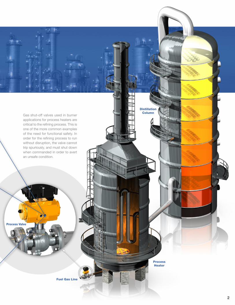
Process Valve
Fuel Gas Line
Process Heater
DistillationColumn
Gas shut-off valves used in burnerapplications for process heaters arecritical to the refining process. This isone of the more common examplesof the need for functional safety. Inorder for the refining process to runwithout disruption, the valve cannottrip spuriously, and must shut downwhen commanded in order to avertan unsafe condition.
2
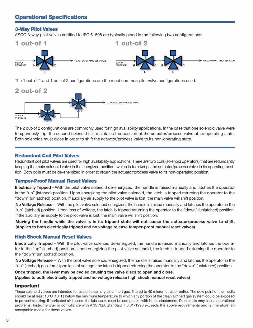
3-Way Pilot ValvesASCO 3-way pilot valves certified to IEC 61508 are typically piped in the following two configurations:
1 out-of 1
P
E
C
TO ACTUATOR / PROCESS VALVE
P
E
C
P
E
C
SUPPLYPRESSURE
SUPPLYPRESSURE
P
E
C
TO ACTUATOR / PROCESS VALVE
P
E
CSUPPLYPRESSURE
TO ACTUATOR / PROCESS VALVE
The 1 out-of 1 and 1 out-of 2 configurations are the most common pilot valve configurations used.
2 out-of 2
The 2 out-of 2 configurations are commonly used for high availability applications. In the case that one solenoid valve wereto spuriously trip, the second solenoid still maintains the position of the actuator/process valve at its operating state. Both solenoids must close in order to shift the actuator/process valve to its non-operating state.
Redundant Coil Pilot ValvesRedundant coil pilot valves are used for high availability applications. There are two coils (solenoid operators) that are redundantlykeeping the main solenoid valve in the energized position, which in turn keeps the actuator/process valve in its operating posi-tion. Both coils must be de-energized in order to return the actuator/process valve to its non-operating position.
Tamper-Proof Manual Reset ValvesElectrically Tripped – With the pilot valve solenoid de-energized, the handle is raised manually and latches the operatorin the “up” (latched) position. Upon energizing the pilot valve solenoid, the latch is tripped returning the operator to the“down” (unlatched) position. If auxiliary air supply to the pilot valve is lost, the main valve will shift position.
No Voltage Release – With the pilot valve solenoid energized, the handle is raised manually and latches the operator in the“up” (latched) position. Upon loss of voltage, the latch is tripped returning the operator to the “down” (unlatched) position.If the auxiliary air supply to the pilot valve is lost, the main valve will shift position.
Moving the handle while the valve is in its tripped state will not cause the actuator/process valve to shift.(Applies to both electrically tripped and no voltage release tamper-proof manual reset valves)
High Shock Manual Reset ValvesElectrically Tripped – With the pilot valve solenoid de-energized, the handle is raised manually and latches the opera-tor in the “up” (latched) position. Upon energizing the pilot valve solenoid, the latch is tripped returning the operator tothe “down” (unlatched) position.
No Voltage Release – With the pilot valve solenoid energized, the handle is raised manually and latches the operator in the“up” (latched) position. Upon loss of voltage, the latch is tripped returning the operator to the “down” (unlatched) position.
Once tripped, the lever may be cycled causing the valve discs to open and close. (Applies to both electrically tripped and no voltage release high shock manual reset valves)
Operational Specifications
ImportantThese solenoid valves are intended for use on clean dry air or inert gas, filtered to 40 micrometres or better. The dew point of the mediashould be at least 10°C (18° F) below the minimum temperature to which any portion of the clean air/inert gas system could be exposedto prevent freezing. If lubricated air is used, the lubricants must be compatible with Nitrile elastomers. Diester oils may cause operationalproblems. Instrument air in compliance with ANSI/ISA Standard 7.0.01-1996 exceeds the above requirements and is, therefore, anacceptable media for these valves.
1 out-of 2
3
PipeSize(in)
OrificeSize(in)
Cv FlowFactor
Operating PressureDifferential (psi)
Fluid andAmbientTemp. °F Brass Body Stainless Steel BodyAir-Inert Gas
Pressure toCylinder
Cylinder toExhaust Min. Max. Min. Max. Catalog Number
Const.Ref. Catalog Number
Const.Ref.
UNIVERSAL OPERATION (Pressure at any port) with NBR Disc – SIL 3 Capable, Certified by Exidaƒ∆
1/4 1/20 0.06 0.06 0 130 -40 149 8314H300 1 8314H301 √ 1NORMALLY CLOSED (Closed when de-energized) with NBR Disc or FPM, as Listed – SIL 3 Capable, Certified by Exidaƒ
1/4 5/16 1.5 1.5 ¬ 130 -20 149 8316H301 ¨ 2 EV8316H381 ¨√ 2A3/8 5/16 1.8 1.8 ¬ 130 -20 149 8316H302 ¨ 2 EV8316H382 ¨√ 2A3/8 5/8 4 4 ¬ 130 -20 149 8316H303 ¨ 3 - -1/2 5/8 4 4 ¬ 130 -20 149 8316H304 ¨ 3 EV8316H384 ¨√ 3A3/4 11/16 5.5 5.5 10 130 -20 149 8316J374 ¨ 4 - -1 1 13 13 10 130 -4 149 8316H334 ¨≈ 5 - -
¨ IMPORTANT: Internal Mode Minimum Operating Pressure Differential must be maintained between the pressure and exhaust ports. Supply and exhaust piping must be full area, unrestricted. ASCO flow controls and other similar components must be installed in the cylinder lines only. See graph on page 6 for main line pressure vs. pilot line pressure.
¬ Zero minimum when valve selection gasket is in external position and proper auxiliary air pressure is applied. Minimum 15 psi Operating Pressure Differential when selection gasket is in the internal position (see graph on page 6 for mainline vs. pilot line pressure).
√ Can be used for dry natural gas service (no agency approvals) with the EF or EV prefix.ƒ Safety manual and FMEDA (Failure Modes Effects and Diagnostic Analysis) report available.≈ Solenoid only approvals with EF or EV prefix, no approvals with general purpose coil (no prefix).∆ SIL 3 Capable, Certified by Exida, only valid when used as Normally Closed.*IMPORTANT: Supervisory and leakage current above the drop out current of 1.8 mA for 24V DC will cause improper operation. Consult your local ASCO sales office for additional assistance.
PipeSize(in)
OrificeSize(in)
CvFlowFactor2-1
CvFlowFactor1-3
Operating PressureDifferential (psi)
Min.Fluid andAmbientTemp. °F
Max.Fluid
Temp. ˚F ≠
Max.AmbientTemp. ˚F
Brass Body Stainless Steel Body Watt Rating/Class of CoilInsulation Max. AC Max. DC
CatalogNumber
Const.Ref.
CatalogNumber
Const.Ref.
Air-InertGas Water
Lt. Oil @45 SSU
Air-InertGas Water
Lt. Oil @45 SSU AC DC AC DC AC DC
NORMALLY CLOSED (Closed when de-energized) – SIL 3 Capable, Certified by Exida¨
1/8 3/64 0.05 0.06 300 300 300 250 250 250 -13 200 200 131 131 8314H031 10 8314H037 10 10.1/F 11.6/F1/8 3/32 0.15 0.20 205 205 190 150 120 90 -13 200 200 131 131 8314H032 10 8314H038 10 10.1/F 11.6/F1/8 1/8 0.25 0.20 145 145 100 90 90 70 -13 200 200 131 131 8314H033 10 8314H039 10 10.1/F 11.6/F1/4 3/64 0.05 0.06 300 300 300 250 250 250 -13 200 200 131 131 8314H034 11 8314H068 11 10.1/F 11.6/F1/4 3/32 0.15 0.20 205 205 190 150 120 90 -13 200 200 131 131 8314H035 11 8314H121 11 10.1/F 11.6/F1/4 1/8 0.25 0.20 145 145 100 90 90 70 -13 200 200 131 131 8314H036 11 8314H126 11 10.1/F 11.6/F1/4 5/32 0.50 0.20 75 75 75 50 50 50 -13 200 200 131 131 8314H130 11 8314H230 11 10.1/F 11.6/F1/4 7/32 0.70 0.20 40 40 40 25 25 25 -13 200 200 131 131 8314H131 11 8314H231 11 10.1/F 11.6/F1/4 9/32 0.85 0.20 25 25 25 15 15 15 -13 200 200 131 131 8314H132 11 8314H232 11 10.1/F 11.6/F
¨ Safety manual and FMEDA (Failure Modes Effects and Diagnostic Analysis) report available.≠ Max. Fluid Temp 180 F for light oil @ 45 SSU
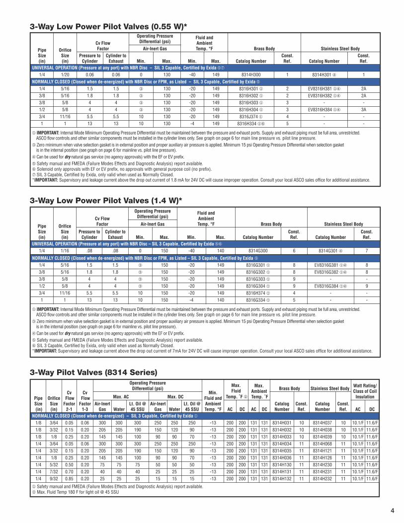
3-Way Pilot Valves (8314 Series)
3-Way Low Power Pilot Valves (0.55 W)*
3-Way Low Power Pilot Valves (1.4 W)*
PipeSize(in)
OrificeSize(in)
Cv FlowFactor
Operating PressureDifferential (psi)
Fluid andAmbientTemp. °F Brass Body Stainless Steel BodyAir-Inert Gas
Pressure toCylinder
Cylinder toExhaust Min. Max. Min. Max. Catalog Number
Const.Ref. Catalog Number
Const.Ref.
UNIVERSAL OPERATION (Pressure at any port) with NBR Disc – SIL 3 Capable, Certified by Exidaƒ≈
1/4 1/16 .08 .08 0 150 -40 140 8314G300 6 8314G301 √ 7
NORMALLY CLOSED (Closed when de-energized) with NBR Disc or FPM, as Listed – SIL 3 Capable, Certified by Exida ƒ
1/4 5/16 1.5 1.5 ¬ 150 -20 149 8316G301 ¨ 8 EV8316G381 ¨√ 83/8 5/16 1.8 1.8 ¬ 150 -20 149 8316G302 ¨ 8 EV8316G382 ¨√ 83/8 5/8 4 4 ¬ 150 -20 149 8316G303 ¨ 9 - -1/2 5/8 4 4 ¬ 150 -20 149 8316G304 ¨ 9 EV8316G384 ¨√ 93/4 11/16 5.5 5.5 10 150 -20 149 8316H374 ¨ 4 - -1 1 13 13 10 150 -4 140 8316G334 ¨ 5 - -
¨ IMPORTANT: Internal Mode Minimum Operating Pressure Differential must be maintained between the pressure and exhaust ports. Supply and exhaust piping must be full area, unrestricted. ASCO flow controls and other similar components must be installed in the cylinder lines only. See graph on page 6 for main line pressure vs. pilot line pressure.
¬ Zero minimum when valve selection gasket is in external position and proper auxiliary air pressure is applied. Minimum 15 psi Operating Pressure Differential when selection gasket is in the internal position (see graph on page 6 for mainline vs. pilot line pressure).
√ Can be used for dry natural gas service (no agency approvals) with the EF or EV prefix.ƒ Safety manual and FMEDA (Failure Modes Effects and Diagnostic Analysis) report available.≈ SIL 3 Capable, Certified by Exida, only valid when used as Normally Closed.*IMPORTANT: Supervisory and leakage current above the drop out current of 7mA for 24V DC will cause improper operation. Consult your local ASCO sales office for additional assistance.
4
PipeSize(in)
OrificeSize(in)
Cv FlowFactor
Operating PressureDifferential (psi)
Min.Fluid and
AmbientTemp. °F
Max.FluidTemp.°F
MaxAmbientTemp. °F
Brass Body 316 Stainless Steel Body
Watt Rating/Class of Coil InsulationMax. DC
Ports1-2
Ports2-3
Air-InertGas Water
Lt. Oil @ 45SSU Catalog Number
Const.Ref. Catalog Number
Const.Ref. AC DC
UNIVERSAL OPERATION (Pressure at any port) – SIL 3 Capable, Certified by Exida¨
1/4 1/4 0.49 0.56 150 150 150 -4 176 131 8327G041 16 - - 12.0/F 11.6/F1/4 1/4 0.49 0.56 150 150 150 -4 248 131 - - EV8327G042 16 12.0/F 11.6/F1/4 1/4 0.49 0.56 150 - - -40 131 131 8327G051 16 - - 12.0/F 11.6/F1/4 1/4 0.49 0.56 150 - - -40 131 131 - - EV8327G052 16 12.0/F 11.6/F
¨ Safety manual and FMEDA (Failure Modes Effects and Diagnostic Analysis) report available. SIL 3 Capable, Certified by Exida, only valid when used as Normally Closed.
PipeSize(in)
OrificeSize(in)
Cv FlowFactor
Operating PressureDifferential (psi)
Fluid and
Ambient Temp °F Aluminum Body
Watt Rating/ Class ofCoil
InsulationAir-Inert
Min. Max. Min. Max. AC Max. DC Catalog NumberConst.Ref. AC DC
NORMALLY CLOSED – OPEN FRAME DIN COIL – SIL 3 Capable, Certified by Exida ¨1/4 1/4 0.86 30 150 5 140 140 SC8551A005MS 17 2.5/F 3.0/F1/2 1/2 3.7 30 150 -15 140 140 SC8553A005MS 17 5.0/F 6.9/F
NORMALLY CLOSED – WATERTIGHT ENCLOSURE – SIL 3 Capable, Certified by Exida ¨1/4 1/4 0.86 30 150 5 140 77 WT8551A005MS 17 6.3/F 6.9/F1/2 1/2 3.7 30 150 -15 140 77 WT8553A005MS 17 6.3/F 6.9/F
NORMALLY CLOSED – EXPLOSIONPROOF ENCLOSURE – SIL 3 Capable, Certified by Exida ¨1/4 1/4 0.86 30 150 5 104 77 EF8551A005MS 17 6.3/F 6.9/F1/2 1/2 3.7 30 150 -15 104 77 EF8553A005MS 17 6.3/F 6.9/F
¨ Safety manual and FMEDA (Failure Modes Effects and Diagnostic Analysis) report available.
PipeSize(in)
OrificeSize(in)
Cv FlowFactor
Operating PressureDifferential (psi)
Fluid Temp. ˚F Ambient Temp. ˚F Aluminum Body Brass Body316L
Stainless Steel Body
Const.Ref.
Watt Rating/Class of Coil InsulationAir-Inert
Min. Max. AC Max. DCMax. AC
Max.DC Min.
Max.AC
Max.DC Catalog Number AC DC
NORMALLY CLOSED – SIL 3 Capable, Certified by Exida ¨1/4 1/4 0.86 30 145 120 140 120 5 125 104 8551G405 - - 18 10.1/F 11.6/F1/4 1/4 0.86 30 145 120 140 120 -40 125 104 - EF8551G407¬ - 18 10.1/F 11.6/F1/4 1/4 0.86 30 145 120 140 120 -40 125 104 - - EV8551G413≠ 18 10.1/F 11.6/F1/2 1/2 3.7 30 145 120 140 120 5 125 104 8553G405 - - 18 10.1/F 11.6/F1/2 1/2 3.7 30 145 120 140 120 -40 125 104 - - EV8553G413≠ 18 10.1/F 11.6/F
¨ Safety manual and FMEDA (Failure Modes Effects and Diagnostic Analysis) report available.≠ Stainless steel construction supplied standard with EV solenoid.¬ Brass construction supplied standard with EF solenoid.
PipeSize(in)
OrificeSize(in)
CvFlowFactor
Operating PressureDifferential (psi)
Min.Fluid andAmbientTemp. °F
Max.FluidTemp. ˚F
Max.AmbientTemp. ˚F
Brass Body Stainless Steel BodyWatt Rating/Class of CoilInsulation ¨Max. AC Max. DC
CatalogNumber
Const.Ref.
CatalogNumber
Const.Ref.
Air-InertGas Water
Lt. Oil@ 300SSU
Air-InertGas Water
Lt. Oil@ 300SSU AC DC AC DC AC DC
NORMALLY CLOSED (Closed when de-energized) – SIL 3 Capable, Certified by Exida√
1/8 3/64 0.06 200 200 200 200 200 200 32 180 120 125 104 8320G132 12 8320G142 ≠ 12 6.1F 10.6/F1/8 1/16 0.09 150 125 125 125 125 125 32 180 120 125 104 8230G013 12 8320G045 ≠ 12 6.1F 10.6/F1/8 1/16 0.09 210 225 225 160 160 160 32 200 150 125 104 8320G215 13 8320G224 ¬ 13 17.1/F 11.6/F1/8 3/32 0.12 100 100 100 100 100 100 32 180 120 125 104 8320G015 12 8320G047 ≠ 12 6.1F 10.6/F1/8 3/32 0.12 150 150 150 115 115 115 32 200 150 125 104 8320G216 13 8320G225 ¬ 13 10.1/F 11.6/F1/8 1/8 0.21 40 40 40 40 40 40 32 180 120 125 104 8320G017 12 8320G049 ≠ 12 6.1F 10.6/F1/8 1/8 0.21 85 85 85 60 60 60 32 200 150 125 104 8320G217 13 8320G226 ¬ 13 10.1/F 11.6/F1/4 1/16 0.09 210 225 225 160 160 160 32 200 150 125 104 8320G182 14 8320G231 ¬ 15 17.1/F 11.6/F1/4 3/32 0.12 150 150 150 115 115 115 32 200 150 125 104 8320G184 14 8320G202 ≠¬ 15 10.1/F 11.6/F1/4 1/8 0.25 85 85 85 60 60 60 32 200 150 125 104 8320G186 14 8320G203 ≠¬ 15 10.1/F 11.6/F1/4 11/64 0.35 45 45 45 25 25 25 32 200 150 125 104 8320G188 14 - - 10.1/F 11.6/F
¨ On 50 hertz service, the watt rating for the 6.1/F solenoid is 8.1 watts≠ Can be used for dry natural gas service with the EF or EV prefix.¬ Constructions standard rated -40˚F ambient temperature. EFX prefix and TPL # not required√ Safety manual and FMEDA (Failure Modes Effects and Diagnostic Analysis) report available.
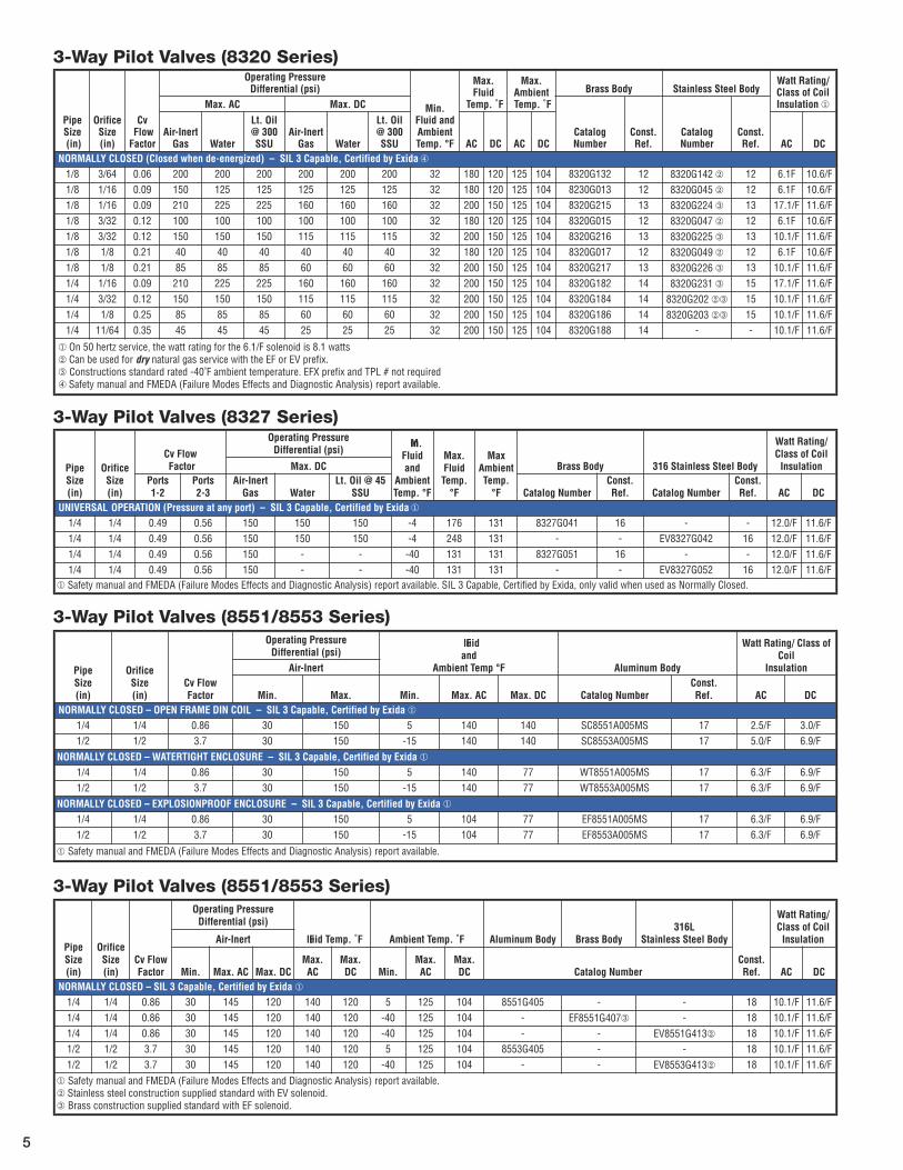
3-Way Pilot Valves (8320 Series)
3-Way Pilot Valves (8327 Series)
3-Way Pilot Valves (8551/8553 Series)
3-Way Pilot Valves (8551/8553 Series)
5
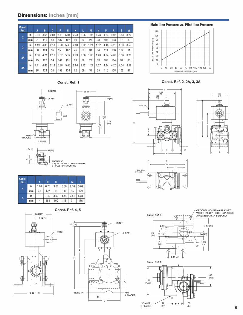
Dimensions: inches [mm]
Const.Ref. A H K L M P
4in 1.61 6.78 3.68 3.38 2.16 5.09
mm 41 172 93 86 55 129
5in - 7.40 3.93 4.44 2.81 5.34
mm - 188 100 113 71 136
1/2 NPT
1/8 NPT.45 [11]
H
P
K
PRESS “P” NPT3 PLACES
L
M
A
OPTIONAL MOUNTING BRACKETWITH Ø .28 [Ø 7] HOLES [4 PLACES] AVAILABLE ON 3/4 SIZE ONLY
3.82 [97]
.50 [13]
1.66[42]
1.66 [42]
CYL“A”
1.41[36]
EXH“E”
3.31[84] .53 [13]
P
E
4.44 [113]
3.04 [77]
2.04 [52]
1/2 NPT
101[4.00]
E
68[2.69]P
A
22[.87]
22[.87]
1” ANPT3 PLACES
Const. Ref. 5
Const. Ref. 4
120
15
30
45
60
75
90
106
0
60 45 30 15 0 135 120 105 90 75 150
PILO
T LI
NE P
RESS
URE
(psi
)
MAIN LINE PRESSURE (psi)
Main Line Pressure vs. Pilot Line PressureConst.Ref. A B C F H K L M N P R S W
2in 0.84 4.68 2.08 5.41 5.01 2.73 2.06 1.06 1.28 4.23 4.06 3.83 3.26
mm 21 119 53 137 127 69 52 27 33 107 103 97 83
3in 1.19 4.88 2.18 5.90 5.40 2.98 2.72 1.24 1.32 4.48 4.26 4.03 3.59
mm 30 124 56 150 167 76 69 31 34 114 108 102 91
2Ain 1.00 4.71 2.11 5.57 5.17 2.73 2.06 1.08 1.28 4.24 4.09 3.86 3.28
mm 25 120 54 141 131 69 52 27 33 108 104 98 83
3Ain 1.11 4.88 2.18 5.98 5.48 2.84 2.72 1.24 1.37 4.34 4.26 4.04 3.59
mm 28 124 55 152 139 72 69 31 35 110 108 102 91
Const. Ref. 1
ANPT3 PLACES
1/8 NPT
1/2 NPT
.45 [11]
2.04 [52]
1.56 [40]
1.95 [50]
.87 [22]
M5 THREAD7.6 [.30] MIN. FULL THREAD DEPTH2 HOLES FOR MOUNTING
.87 [22]
.34 [9]
3.35[85]
3.71[94]1.84
[47]
S
N M
F
W
R
B
C
HK
P
L
1/2 NPT
A
3.06[78]
2.06[52]
1.95[50]
Ø28 [7](4 Places)
Const. Ref. 2, 2A, 3, 3A
Const. Ref. 4, 5
6
1.95 [50]
1/8 NPT
1/2 NPT
.45 [11]
4.25[108]
5.05[128]
5.52[140]
2.84[72]
.30 [8]
CYL
2.06 [52]
.16 [4]
.78[20]
1.31 [33]OPTIONAL MOUNTING
BRACKET WITHØ.28 [Ø7] HOLES
4 PLACES
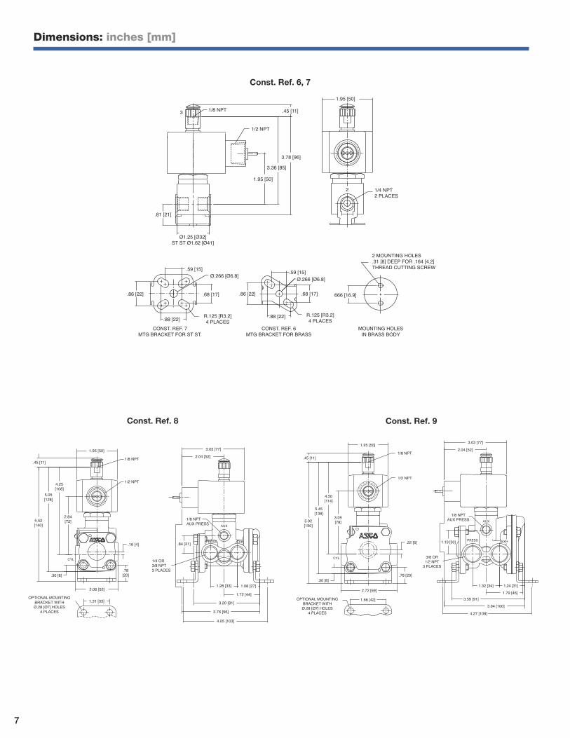
3.03 [77]2.04 [52]
1/4 OR3/8 NPT3 PLACES
.84 [21]
1/8 NPTAUX PRESS
1.28 [33] 1.08 [27]
1.72 [44]
3.20 [81]
3.76 [96]
4.05 [103]
AUX
PRESS EXH
1.95 [50]
.45 [11]
4.50[114]
3.09[78]
5.45[138]
5.92[150]
CYL
.30 [8]
2.72 [69]
1.66 [42]
1/8 NPT
1/2 NPT
.22 [6]
.78 [20]
OPTIONAL MOUNTINGBRACKET WITHØ.28 [Ø7] HOLES
4 PLACES
3.03 [77]2.04 [52]
1/8 NPTAUX PRESS
1.19 [30]
3/8 OR1/2 NPT
3 PLACES
4.27 [108]3.94 [100]
3.59 [91]
1.32 [34] 1.24 [31]1.79 [46]
AUX
PRESS EXH
Const. Ref. 9Const. Ref. 8
Dimensions: inches [mm]
3 1/8 NPT .45 [11]
1/2 NPT
3.78 [96]
3.36 [85]
1.95 [50]
.81 [21]
1.95 [50]
1/4 NPT2 PLACES
2
2 MOUNTING HOLES.31 [8] DEEP FOR .164 [4.2]THREAD CUTTING SCREW
MOUNTING HOLESIN BRASS BODY
666 [16.9]
CONST. REF. 7MTG BRACKET FOR ST ST.
CONST. REF. 6MTG BRACKET FOR BRASS
.86 [22]
.59 [15]
.68 [17]
.88 [22] R.125 [R3.2]4 PLACES
Ø1.25 [Ø32]ST ST Ø1.62 [Ø41]
Ø.266 [Ø6.8]
.86 [22]
.88 [22]
.59 [15]Ø.266 [Ø6.8]
.68 [17]
R.125 [R3.2]4 PLACES
Const. Ref. 6, 7
7
2 MOUNTING HOLES.164 [4] THD CUTTING SCREW
2
1
.44 [11]
R.09 [2.3]4 PLACESFOR MOUNTING
.44 [11]
Ø 1.19 [30]
.09 [2.3]2 PLACES
1.30[33]
.63[16]
1/8 NPT3 PLACES
3
1.32[34]
1.69 [43]
2.18[55]
3.15[80]
1/2 NPT
.090 [2.3]2 PLACES
CUTTING SCREWFOR .164 [4.2] THREAD 2 MOUNTING HOLES
MOUNTING BRACKET
.440 [11.2]
.440 [11.2]R.090 [2.3]
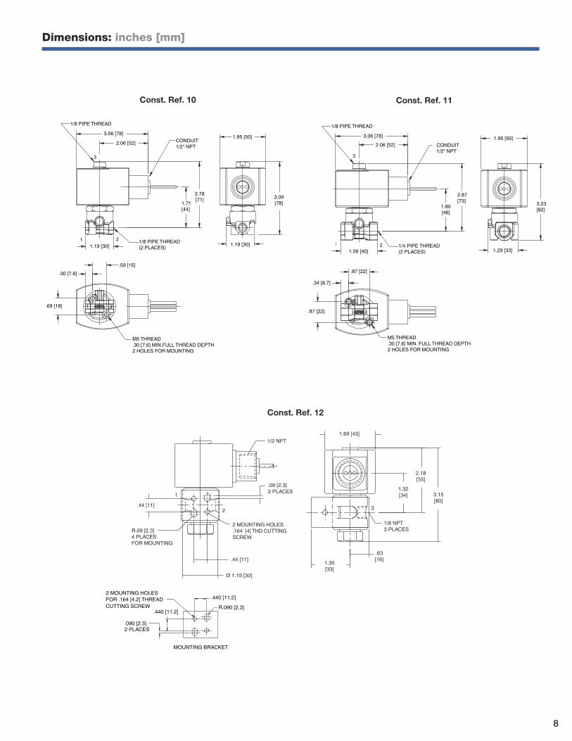
Const. Ref. 12
Dimensions: inches [mm]
.30 [7.6]
2.78[71]
2.06 [52]
3.06 [78]1.95 [50]
3.09[78]1.71
[44]
21
3
1/8 PIPE THREAD
1/8 PIPE THREAD(2 PLACES)
M5 THREAD.30 [7.6] MIN.FULL THREAD DEPTH2 HOLES FOR MOUNTING
1.19 [30] 1.19 [30]
.69 [18]
.59 [15]
CONDUIT1/2" NPT
Const. Ref. 10
.34 [8.7]
2.87[73]
2.06 [52]
3.06 [78] 1.95 [50]
3.23[82]
1.80[46]
1 2
3
1/8 PIPE THREAD
1/4 PIPE THREAD(2 PLACES)
CONDUIT1/2" NPT
M5 THREAD.30 [7.6] MIN. FULL THREAD DEPTH2 HOLES FOR MOUNTING
1.56 [40] 1.29 [33]
.87 [22]
.87 [22]
Const. Ref. 11
8
Dimensions: inches [mm]
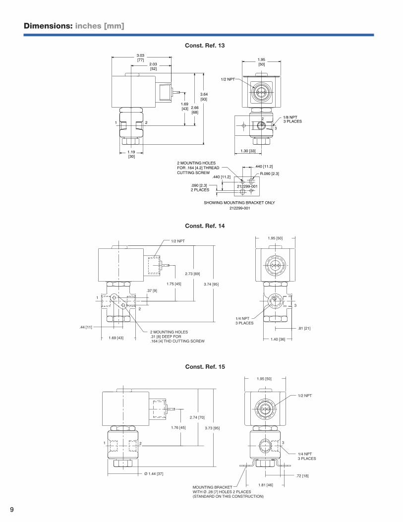
Ø 1.44 [37]
1.76 [45]
2.74 [70]
3.73 [95]
1.95 [50]
1/2 NPT
1/4 NPT3 PLACES
.72 [18]
1.81 [46]MOUNTING BRACKETWITH Ø .28 [7] HOLES 2 PLACES(STANDARD ON THIS CONSTRUCTION)
1 2 3
Const. Ref. 15
1.69 [43]
.44 [11]
3.74 [95]
2.73 [69]
1.75 [45]
.37 [9]
2 MOUNTING HOLES.31 [8] DEEP FOR.164 [4] THD CUTTING SCREW
1/4 NPT3 PLACES
1.40 [36]
.81 [21]
3
1.95 [50]1/2 NPT
1
2
Const. Ref. 14
.090 [2.3]2 PLACES
212299-001
CUTTING SCREWFOR .164 [4.2] THREAD 2 MOUNTING HOLES
212299-001
SHOWING MOUNTING BRACKET ONLY
1.30 [33]
3
221
1/2 NPT
1.95 [50]
3.64 [93]
2.03 [52]
3.03 [77]
1/8 NPT 3 PLACES
1.19 [30]
1.69 [43] 2.66
[68]
.440 [11.2]
.440 [11.2]R.090 [2.3]
Const. Ref. 13
9
Dimensions: inches [mm]
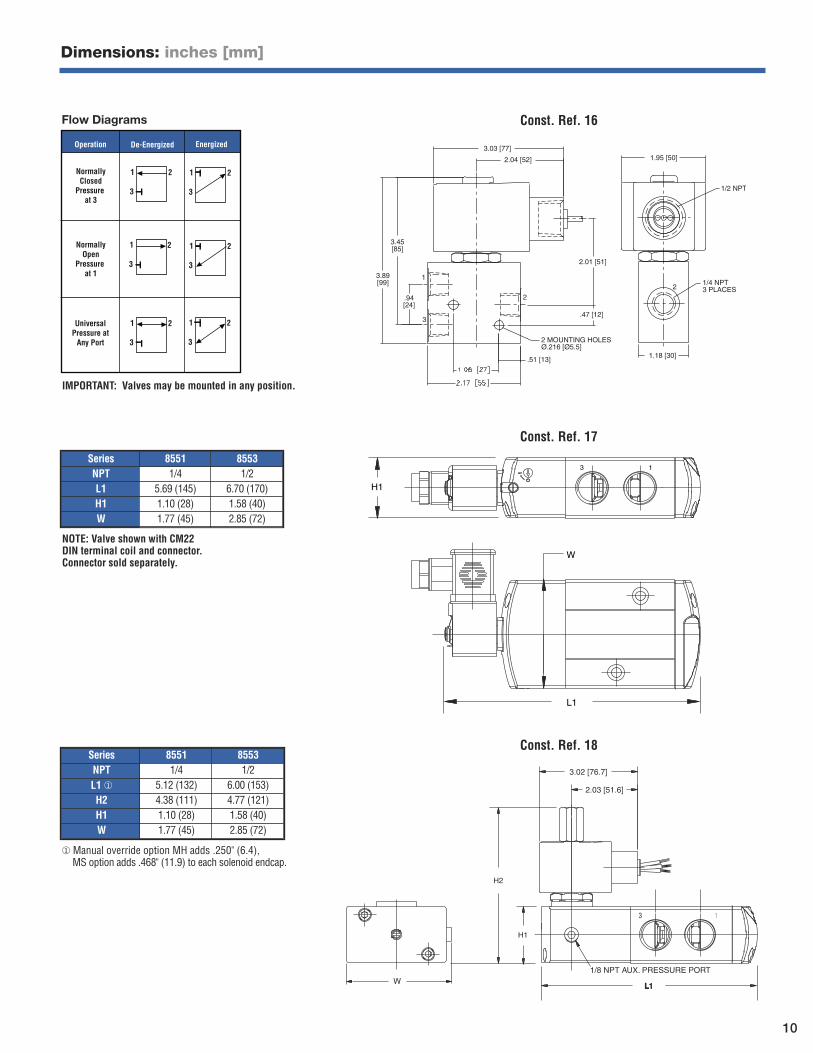
Series 8551 8553NPT 1/4 1/2L1 5.69 (145) 6.70 (170)H1 1.10 (28) 1.58 (40)W 1.77 (45) 2.85 (72)
NOTE: Valve shown with CM22 DIN terminal coil and connector.Connector sold separately.
3.45[85]
3.89[99]
.94[24]
1
3
2
2.01 [51]
.47 [12]
2 MOUNTING HOLESØ.216 [Ø5.5]
.51 [13]
3.03 [77]
2.04 [52] 1.95 [50]
1/2 NPT
1/4 NPT3 PLACES2
1.18 [30]
Const. Ref. 16
IMPORTANT: Valves may be mounted in any position.
Operation De-Energized Energized
1
3
2
1
3
2
1
3
2 1
3
2
1
3
2
1
3
2NormallyClosed
Pressure at 3
NormallyOpen
Pressure at 1
UniversalPressure at
Any Port
Flow Diagrams
Const. Ref. 18
2.03 [51.6]
3.02 [76.7]
H2
H1
L1LL1
3 1
W
1/8 NPT AUX. PRESSURE PORT
Series 8551 8553NPT 1/4 1/2L1 ¨ 5.12 (132) 6.00 (153)H2 4.38 (111) 4.77 (121)H1 1.10 (28) 1.58 (40)W 1.77 (45) 2.85 (72)
¨ Manual override option MH adds .250" (6.4), MS option adds .468" (11.9) to each solenoid endcap.
13
L1
H1
W
Const. Ref. 17
10
Dimensions: inches [mm]
Pipe Size (in)
Orifice Size (in)
Cv Flow Factor
Operating Pressure Differential (psi)
FluidTemp. °F
Max.AmbientTemp. ˚F
CatalogNumber
Const.Ref. Body Material Pilot Construction
Watt Rating/ Class of Coil Insulation per Solenoid
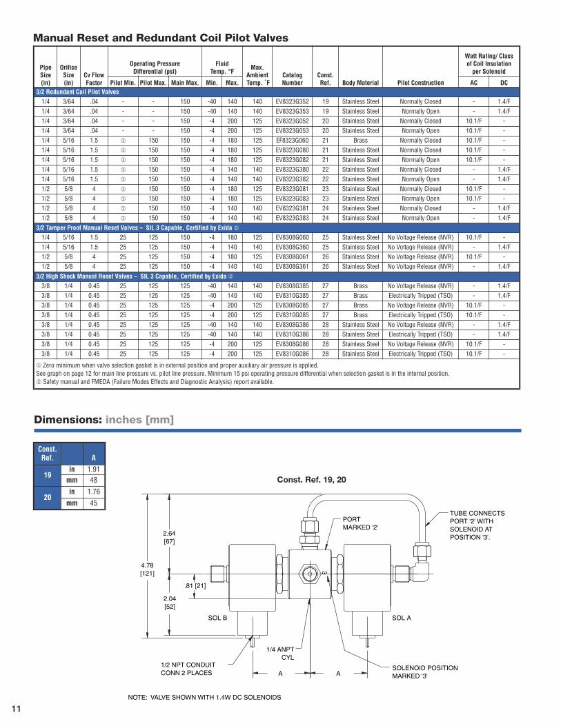
Pilot Min. Pilot Max. Main Max. Min. Max. AC DC3/2 Redundant Coil Pilot Valves1/4 3/64 .04 - - 150 -40 140 140 EV8323G352 19 Stainless Steel Normally Closed - 1.4/F1/4 3/64 .04 - - 150 -40 140 140 EV8323G353 19 Stainless Steel Normally Open - 1.4/F1/4 3/64 .04 - - 150 -4 200 125 EV8323G052 20 Stainless Steel Normally Closed 10.1/F -1/4 3/64 .04 - - 150 -4 200 125 EV8323G053 20 Stainless Steel Normally Open 10.1/F -1/4 5/16 1.5 ¨ 150 150 -4 180 125 EF8323G060 21 Brass Normally Closed 10.1/F -1/4 5/16 1.5 ¨ 150 150 -4 180 125 EV8323G080 21 Stainless Steel Normally Closed 10.1/F -1/4 5/16 1.5 ¨ 150 150 -4 180 125 EV8323G082 21 Stainless Steel Normally Open 10.1/F -1/4 5/16 1.5 ¨ 150 150 -4 140 140 EV8323G380 22 Stainless Steel Normally Closed - 1.4/F1/4 5/16 1.5 ¨ 150 150 -4 140 140 EV8323G382 22 Stainless Steel Normally Open - 1.4/F1/2 5/8 4 ¨ 150 150 -4 180 125 EV8323G081 23 Stainless Steel Normally Closed 10.1/F -1/2 5/8 4 ¨ 150 150 -4 180 125 EV8323G083 23 Stainless Steel Normally Open 10.1/F -1/2 5/8 4 ¨ 150 150 -4 140 140 EV8323G381 24 Stainless Steel Normally Closed - 1.4/F1/2 5/8 4 ¨ 150 150 -4 140 140 EV8323G383 24 Stainless Steel Normally Open - 1.4/F
3/2 Tamper Proof Manual Reset Valves – SIL 3 Capable, Certified by Exida ≠1/4 5/16 1.5 25 125 150 -4 180 125 EV8308G060 25 Stainless Steel No Voltage Release (NVR) 10.1/F -1/4 5/16 1.5 25 125 150 -4 140 140 EV8308G360 25 Stainless Steel No Voltage Release (NVR) - 1.4/F1/2 5/8 4 25 125 150 -4 180 125 EV8308G061 26 Stainless Steel No Voltage Release (NVR) 10.1/F -1/2 5/8 4 25 125 150 -4 140 140 EV8308G361 26 Stainless Steel No Voltage Release (NVR) - 1.4/F
3/2 High Shock Manual Reset Valves – SIL 3 Capable, Certified by Exida ≠3/8 1/4 0.45 25 125 125 -40 140 140 EV8308G385 27 Brass No Voltage Release (NVR) - 1.4/F3/8 1/4 0.45 25 125 125 -40 140 140 EV8310G385 27 Brass Electrically Tripped (TSO) - 1.4/F3/8 1/4 0.45 25 125 125 -4 200 125 EV8308G085 27 Brass No Voltage Release (NVR) 10.1/F -3/8 1/4 0.45 25 125 125 -4 200 125 EV8310G085 27 Brass Electrically Tripped (TSO) 10.1/F -3/8 1/4 0.45 25 125 125 -40 140 140 EV8308G386 28 Stainless Steel No Voltage Release (NVR) - 1.4/F3/8 1/4 0.45 25 125 125 -40 140 140 EV8310G386 28 Stainless Steel Electrically Tripped (TSO) - 1.4/F3/8 1/4 0.45 25 125 125 -4 200 125 EV8308G086 28 Stainless Steel No Voltage Release (NVR) 10.1/F -3/8 1/4 0.45 25 125 125 -4 200 125 EV8310G086 28 Stainless Steel Electrically Tripped (TSO) 10.1/F -
¨ Zero minimum when valve selection gasket is in external position and proper auxiliary air pressure is applied. See graph on page 12 for main line pressure vs. pilot line pressure. Minimum 15 psi operating pressure differential when selection gasket is in the internal position.≠ Safety manual and FMEDA (Failure Modes Effects and Diagnostic Analysis) report available.
A
.81 [21]
A
2.64[67]
4.78[121]
SOL B SOL A
CYL1/4 ANPT
1/2 NPT CONDUIT CONN 2 PLACES
3
TUBE CONNECTS PORT '2' WITH SOLENOID AT POSITION '3'.
SOLENOID POSITIONMARKED '3'
PORTMARKED '2'
2.04[52]
NOTE: VALVE SHOWN WITH 1.4W DC SOLENOIDS
Const. Ref. 19, 20
Manual Reset and Redundant Coil Pilot Valves
Const.Ref. A
19in 1.91mm 48
20in 1.76
mm 45
11
Dimensions: inches [mm]
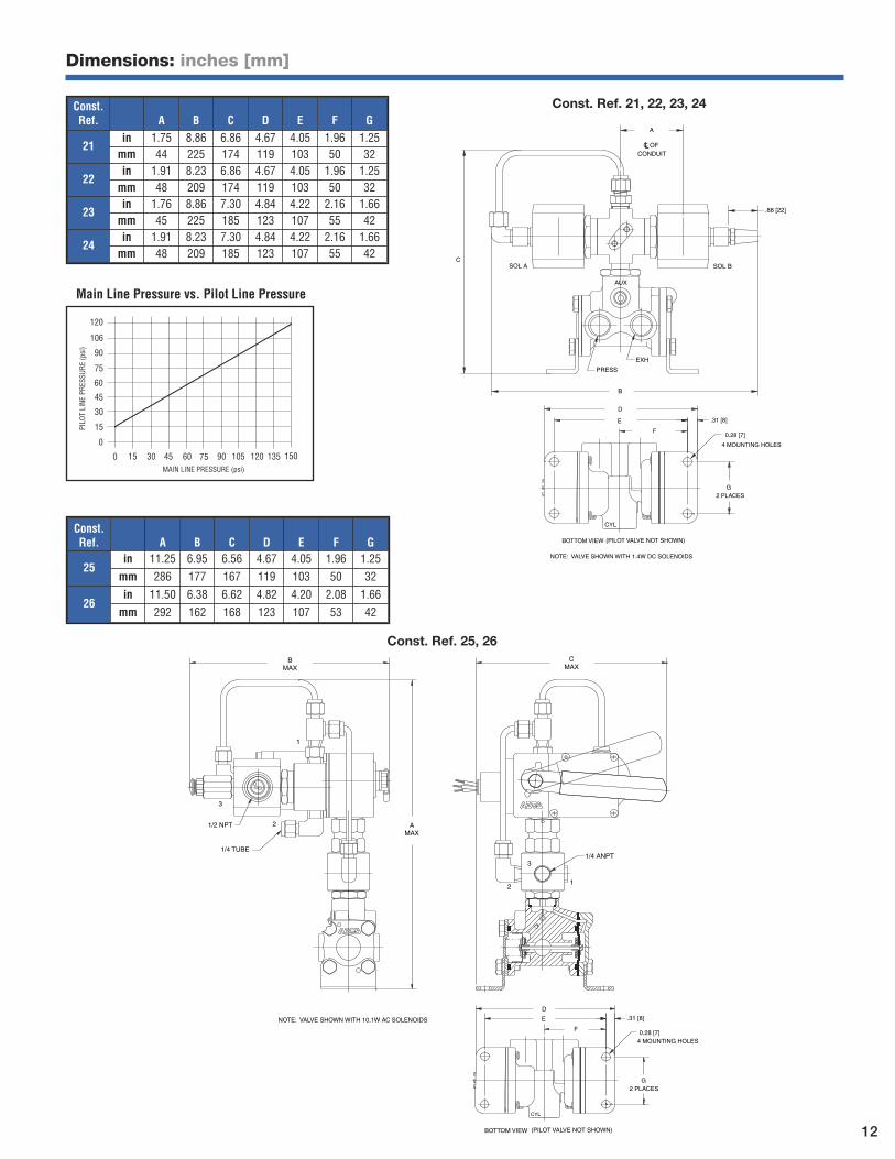
Const.Ref. A B C D E F G
21in 1.75 8.86 6.86 4.67 4.05 1.96 1.25mm 44 225 174 119 103 50 32
22in 1.91 8.23 6.86 4.67 4.05 1.96 1.25mm 48 209 174 119 103 50 32
23in 1.76 8.86 7.30 4.84 4.22 2.16 1.66mm 45 225 185 123 107 55 42
24in 1.91 8.23 7.30 4.84 4.22 2.16 1.66mm 48 209 185 123 107 55 42
EXH
PRESS
CONDUITLC OF
SOL A SOL B
AUX
.88 [22]
A
4 MOUNTING HOLES
D
E .31 [8]
F
G
0.28 [7]
2 PLACES
CYL
BOTTOM VIEW (PILOT VALVE NOT SHOWN)
B
C
NOTE: VALVE SHOWN WITH 1.4W DC SOLENOIDS
Const. Ref. 21, 22, 23, 24
120
15
30
45
60
75
90
106
0
60 45 30 15 0 135 120 105 90 75 150
PILO
T LI
NE P
RESS
URE
(psi
)
MAIN LINE PRESSURE (psi)
Main Line Pressure vs. Pilot Line Pressure
Const. Ref. 25, 26
21
3
2
3
1
1/4 ANPT1/4 TUBE
1/2 NPT AMAX
CMAX
BMAX
4 MOUNTING HOLES
D
E .31 [8]
F
G
0.28 [7]
2 PLACES
CYL
BOTTOM VIEW (PILOT VALVE NOT SHOWN)
NOTE: VALVE SHOWN WITH 10.1W AC SOLENOIDS
Const.Ref. A B C D E F G
25in 11.25 6.95 6.56 4.67 4.05 1.96 1.25mm 286 177 167 119 103 50 32
26in 11.50 6.38 6.62 4.82 4.20 2.08 1.66mm 292 162 168 123 107 53 42
12
Dimensions: inches [mm]
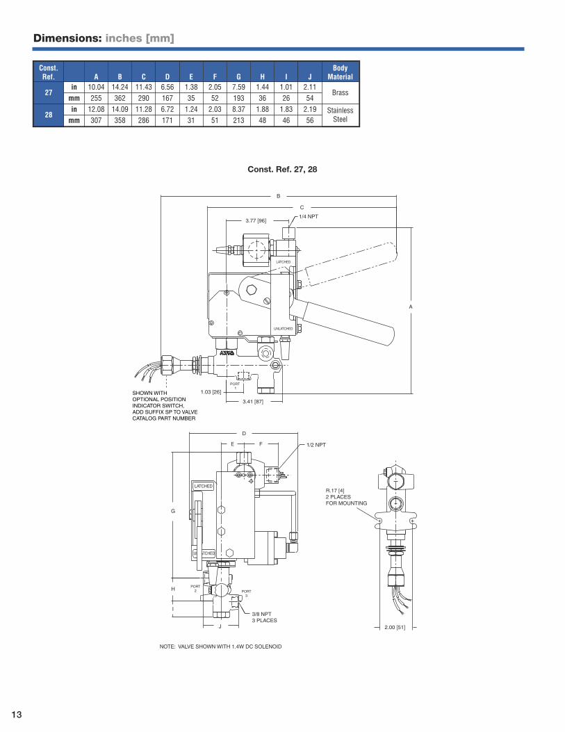
SHOWN WITH OPTIONAL POSITIONINDICATOR SWITCH,ADD SUFFIX SP TO VALVECATALOG PART NUMBER
B
C
1/4 NPT3.77 [96]
A
3.41 [87]
1.03 [26]
PORT 1
UNLATCHED
LATCHED
D
E F 1/2 NPT
G
HPORT
2 PORT3
J
3/8 NPT3 PLACES
2.00 [51]
R.17 [4]2 PLACESFOR MOUNTING
LATCHED
I
NOTE: VALVE SHOWN WITH 1.4W DC SOLENOID
Const. Ref. 27, 28
Const.Ref. A B C D E F G H I J
Body Material
27in 10.04 14.24 11.43 6.56 1.38 2.05 7.59 1.44 1.01 2.11
Brassmm 255 362 290 167 35 52 193 36 26 54
28in 12.08 14.09 11.28 6.72 1.24 2.03 8.37 1.88 1.83 2.19 Stainless
Steelmm 307 358 286 171 31 51 213 48 46 56
13
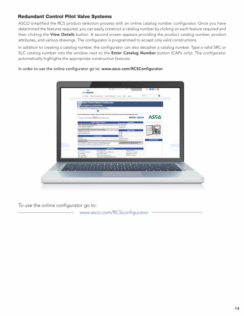
ASCO simplified the RCS product selection process with an online catalog number configurator. Once you have determined the features required, you can easily construct a catalog number by clicking on each feature required andthen clicking the View Details button. A second screen appears providing the product catalog number, product attributes, and various drawings. The configurator is programmed to accept only valid constructions.
In addition to creating a catalog number, the configurator can also decipher a catalog number. Type a valid 5RC or5LC catalog number into the window next to the Enter Catalog Number button (CAPs only). The configurator automatically highlights the appropriate construction features.
In order to use the online configurator go to: www.asco.com/RCSConfigurator
Redundant Control Pilot Valve Systems
14
www.asco.com/RCSconfigurator
To use the online configurator go to:

ASCO Headquarters (USA) | Tel (1) 800.972.2726 | www.asco.com | e-mail: [email protected] 01/17 — V7666R5
Global Contacts
Australia (61) 2-9454-6400Brazil (55) 11-4208-1700Canada (1) 519-758-2700China (86) 21-3395-0000Czech Republic (420) 235-090-061Dubai - UAE (971) 4 811 8200
France (33) 2-37-24-42-24Germany (49) 7237-9960India (91) 44-39197300Italy (39) 02-356931Japan (81) 798-65-6361Mexico (52) 55-5809-5640
Netherlands (31) 33-277-7911Singapore (65) 6556-1100South Korea (82) 2-3483-1570Spain (34) 942-87-6100United Kingdom (44) 1695-713600


![IEC 61508 Assessment - exida€¦ · IEC 61508 Functional Safety Assessment ... [D38] QP 01; Rev 03; 4/29/2009 ... RP Approved Vendor; 7/6/2012 Approved Vendor List [D57]](https://img.pdfslide.us/doc/110x75/5b8675187f8b9a162d8d0076/iec-61508-assessment-iec-61508-functional-safety-assessment-d38-qp-01.jpg)