Embed Size (px)
Citation preview

7/23/2019 Functional Profile for Modbus CIU 200-MPC
http://slidepdf.com/reader/full/functional-profile-for-modbus-ciu-200-mpc 1/38
Grundfos CIU 200Modbus RTU for Grundfos Hydro MPC, Control MPCand Multi-E
GRUNDFOS INSTRUCTIONS
Functional profile and user manual
GRUNDFOS INSTRUCTIONS
Grundfos CIU 200Modbus RTU for Grundfos Hydro MPC, Control MPC and Multi-E
Functional profile and user manual
7/23/2019 Functional Profile for Modbus CIU 200-MPC
http://slidepdf.com/reader/full/functional-profile-for-modbus-ciu-200-mpc 2/382
Original installation and operating instructi ons.
CONTENTS
Page
1. Symbols used in th is document
2. Introduc tion
2.1 About this functional profileThis functional profile describes the CIU 200 (ModbusCommunication Interface Unit 200) for the following products:
• Grundfos Hydro MPC/Control MPC (CU 351)
• Grundfos Hydro Multi-E.
In the following, the CIU 200 is referred to as "communicationinterface", and the Hydro MPC, Control MPC and Hydro Multi-Eare referred to as "controller".
The data in this document are subject to change without prior notice. Grundfos cannot be held responsible for any problemscaused directly or indirectly by using information in this functionalprofile.
2.2 Assumptions
This functional profile assumes that the reader is familiar withcommissioning and programming Modbus devices. The reader should also have some basic knowledge of the Modbus protocoland technical specifications.
It is also assumed that an existing Modbus RTU network with aModbus master is present.
2.3 Definiti ons and abbreviations
1. Sy mb ol s us ed i n t hi s do cu men t 2
2. Introduction 2
2.1 About this functional profile 22.2 Assumptions 22.3 Definitions and abbreviations 22.4 System diagram 3
2.5 Specifications 43. Modbus interface 5
3.1 Modbus bus topology 53.2 CIM 200 Modbus module 53.3 Connecting the Modbus 63.4 Setting the Modbus transmission speed 63.5 Setting the pari ty 63.6 Modbus address selection 73.7 Termination resistor 73.8 LEDs 7
4. Functional p rofile 8
4.1 Register block overview 84.2 CIM configuration register block 84.3 CIM status register block 9
4.4 Control register block 104.5 Status register block 114.6 Data register b lock 134.7 Subpump 1 register block 144.8 Subpump 2 register block 144.9 Subpump 3 register block 154.10 Subpump 4 register block 154.11 Subpump 5 register block 164.12 Subpump 6 register block 16
5. Detai led d es cr ip ti on s 17
5.1 Cont rol modes 175.2 Setpoint 18
6. Commissioning 19
6.1 Step-by-step guide to hardware setup (CIU 200) 19
7. Fault finding 207.1 LED status 207.2 Modbus communication faults 21
8. Data i tem o ver vi ew 22
8.1 Temperature calculation 24
9. Grundfos alarm and warning codes 25
10. Mo db us ad dr es s 27
11. Modbus telegrams and function codes 28
11.1 Modbus telegram overview 2811.2 Function code overview 2811.3 Read holding registers (0x03) 2911.4 Read input registers (0x04) 2911.5 Write single register (0x06) 2911.6 Write multiple registers (0x10) 3011.7 Diagnostics (0x08) 3111.8 Diagnostics register interpretation 32
12. Modbus telegram examples 33
12.1 Diagnostics: return query data 3312.2 Reading CIM configuration register block 3312.3 Setting the setpoint 3312.4 Setting the control mode 3312.5 Starting the controller 3412.6 Stopping the controller 34
Caution
If these safety ins tructions are not observed,
it may result in malfunction or damage to the
equipment!
NoteNotes or instruct ions that make the job easier
and ensure safe operation.
CIM 200 Communication Interface Module(built into the CIU 200)
CIU 200 Communication Interface Unit
CRC Cyclic Redundancy Check, a data error detection method
Derivation cable Stub cable
GENIbus Proprietary Grundfos fieldbus standard
H Pressure (Head)
Hydro MPC Grundfos Hydro Multi-Pump Controller
LED Light-Emitting Diode
Modbus A serial communications protocolcommonly used in industry and buildingservices
Q Flow
RTU Remote Terminal Unit
Transmission speed Bits transferred per second
Trunk cable Main RS-485 cable on Modbus network
7/23/2019 Functional Profile for Modbus CIU 200-MPC
http://slidepdf.com/reader/full/functional-profile-for-modbus-ciu-200-mpc 3/383
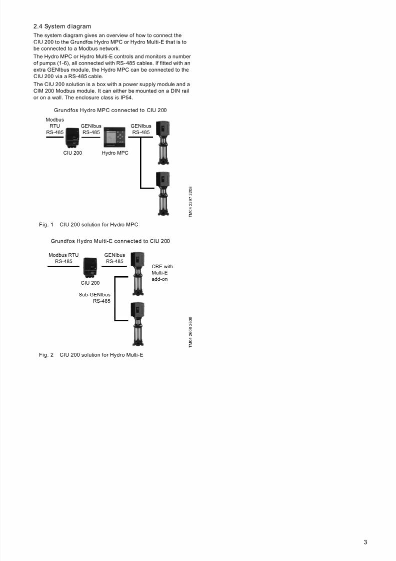
2.4 System d iagram
The system diagram gives an overview of how to connect theCIU 200 to the Grundfos Hydro MPC or Hydro Multi-E that is tobe connected to a Modbus network.
The Hydro MPC or Hydro Multi-E controls and monitors a number of pumps (1-6), all connected with RS-485 cables. If fitted with anextra GENIbus module, the Hydro MPC can be connected to theCIU 200 via a RS-485 cable.
The CIU 200 solution is a box with a power supply module and aCIM 200 Modbus module. It can either be mounted on a DIN rail
or on a wall. The enclosure class is IP54.
Fig. 1 CIU 200 solution for Hydro MPC
Fig. 2 CIU 200 solution for Hydro Multi-E
T M 0 4 2 2 9 7
2 2 0 8
T M 0 4 2 6 0 8 2 6 0 8
Grundfos Hydro MPC connected to CIU 200
Modbus
RTU
RS-485
GENIbus
RS-485
GENIbus
RS-485
Hydro MPCCIU 200
Grundfos Hydro MPC connected to CIU 200
ModbusRTU
RS-485
CIU 200
GENIbusRS-485
GENIbusRS-485
Hydro MPC
Grundfos Hydro Multi-E connected to CIU 200
Modbus RTU
RS-485
GENIbus
RS-485
Sub-GENIbus
RS-485
CRE with
Multi-E
add-on
CIU 200
Grundfos Hydro Multi-E connected to CIU 200
CIU 200
GENIbusRS-485
Modbus RTURS-485
CRE withMulti-Eadd-on
Sub-GENIbusRS-485
7/23/2019 Functional Profile for Modbus CIU 200-MPC
http://slidepdf.com/reader/full/functional-profile-for-modbus-ciu-200-mpc 4/384
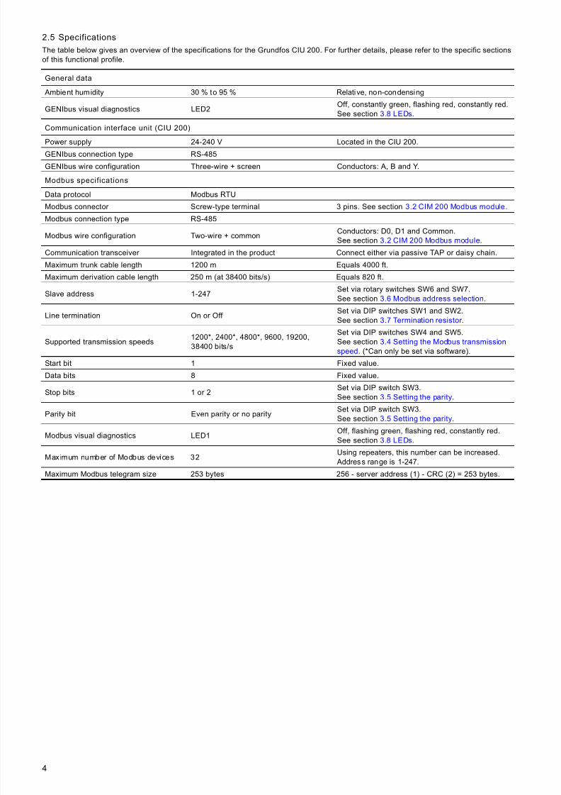
2.5 Specifications
The table below gives an overview of the specifications for the Grundfos CIU 200. For further details, please refer to the specific sectionsof this functional profile.
General data
Ambient humidity 30 % to 95 % Relative, non-condensing
GENIbus visual diagnostics LED2Off, constantly green, flashing red, constantly red.See section 3.8 LEDs.
Communication interface unit (CIU 200)
Power supply 24-240 V Located in the CIU 200.
GENIbus connection type RS-485
GENIbus wire configuration Three-wire + screen Conductors: A, B and Y.
Modbus specifications
Data protocol Modbus RTU
Modbus connector Screw-type terminal 3 pins. See section 3.2 CIM 200 Modbus module.
Modbus connection type RS-485
Modbus wire configuration Two-wire + commonConductors: D0, D1 and Common.See section 3.2 CIM 200 Modbus module.
Communication transceiver Integrated in the product Connect either via passive TAP or daisy chain.
Maximum trunk cable length 1200 m Equals 4000 ft.
Maximum derivation cable length 250 m (at 38400 bits/s) Equals 820 ft.
Slave address 1-247Set via rotary switches SW6 and SW7.See section 3.6 Modbus address selection.
Line termination On or Off Set via DIP switches SW1 and SW2.See section 3.7 Termination resistor .
Supported transmission speeds1200*, 2400*, 4800*, 9600, 19200,38400 bits/s
Set via DIP switches SW4 and SW5.See section 3.4 Setting the Modbus transmission
speed. (*Can only be set via software).
Start bit 1 Fixed value.
Data bits 8 Fixed value.
Stop bits 1 or 2Set via DIP switch SW3.See section 3.5 Setting the parity.
Parity bit Even parity or no parity
Set via DIP switch SW3.
See section 3.5 Setting the parity.
Modbus visual diagnostics LED1Off, flashing green, flashing red, constantly red.See section 3.8 LEDs.
Maximum number of Modbus devices 32Using repeaters, this number can be increased.
Address range is 1-247.
Maximum Modbus telegram size 253 bytes 256 - server address (1) - CRC (2) = 253 bytes.
7/23/2019 Functional Profile for Modbus CIU 200-MPC
http://slidepdf.com/reader/full/functional-profile-for-modbus-ciu-200-mpc 5/385
3. Modbus interface
3.1 Modbus bus topol ogy
The Grundfos CIU 200 is connected as a Modbus slave directly tothe Modbus RTU network. This is done either in daisy chain style,or using a passive TAP and a derivation cable (stub).Both methods are exemplified below.
Fig. 3 Example of Modbus network with termination
In such a network, only one master device is connected to theserial bus, and one or several (maximum 247) slaves are alsoconnected to the serial bus. Slaves cannot communicate witheach other and will never transmit data without receiving arequest from the master device.
Up to 32 devices can be connected to one RS-485 Modbussystem without using a repeater. To implement a larger number of devices, use a repeater to connect the smaller networks to larger networks. Repeaters are also used to extend the maximumtransmission distance.
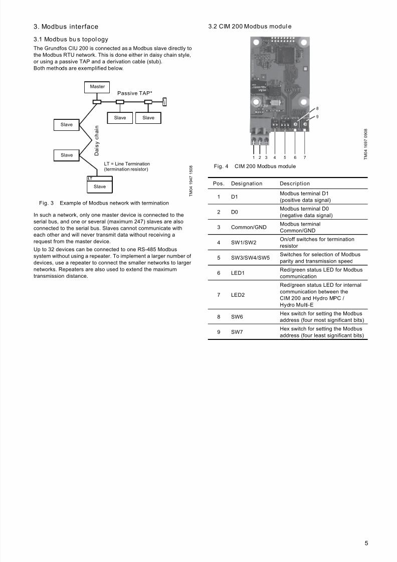
3.2 CIM 200 Modbus modul e
Fig. 4 CIM 200 Modbus module
T M 0 4 1 9 4 7 1 5 0 8
Master
Slave
LT = Line Termination(termination resistor)
Slave
Slave
Slave Slave
D a i s y
c h a i n
Passive TAP*
T M 0 4 1 6 9 7 0 9 0 8
Pos. Designation Description
1 D1Modbus terminal D1(positive data signal)
2 D0Modbus terminal D0(negative data signal)
3 Common/GNDModbus terminalCommon/GND
4 SW1/SW2On/off switches for terminationresistor
5 SW3/SW4/SW5Switches for selection of Modbusparity and transmission speed
6 LED1Red/green status LED for Modbuscommunication
7 LED2
Red/green status LED for internalcommunication between theCIM 200 and Hydro MPC /Hydro Multi-E
8 SW6Hex switch for setting the Modbusaddress (four most significant bits)
9 SW7Hex switch for setting the Modbusaddress (four least significant bits)
1 2 3 4 5 6 7
8
9
7/23/2019 Functional Profile for Modbus CIU 200-MPC
http://slidepdf.com/reader/full/functional-profile-for-modbus-ciu-200-mpc 6/386
3.3 Connecting the Modbus
A screened, twisted-pair cable must be used. The cable screenmust be connected to protective earth at both ends.
Recommended connection
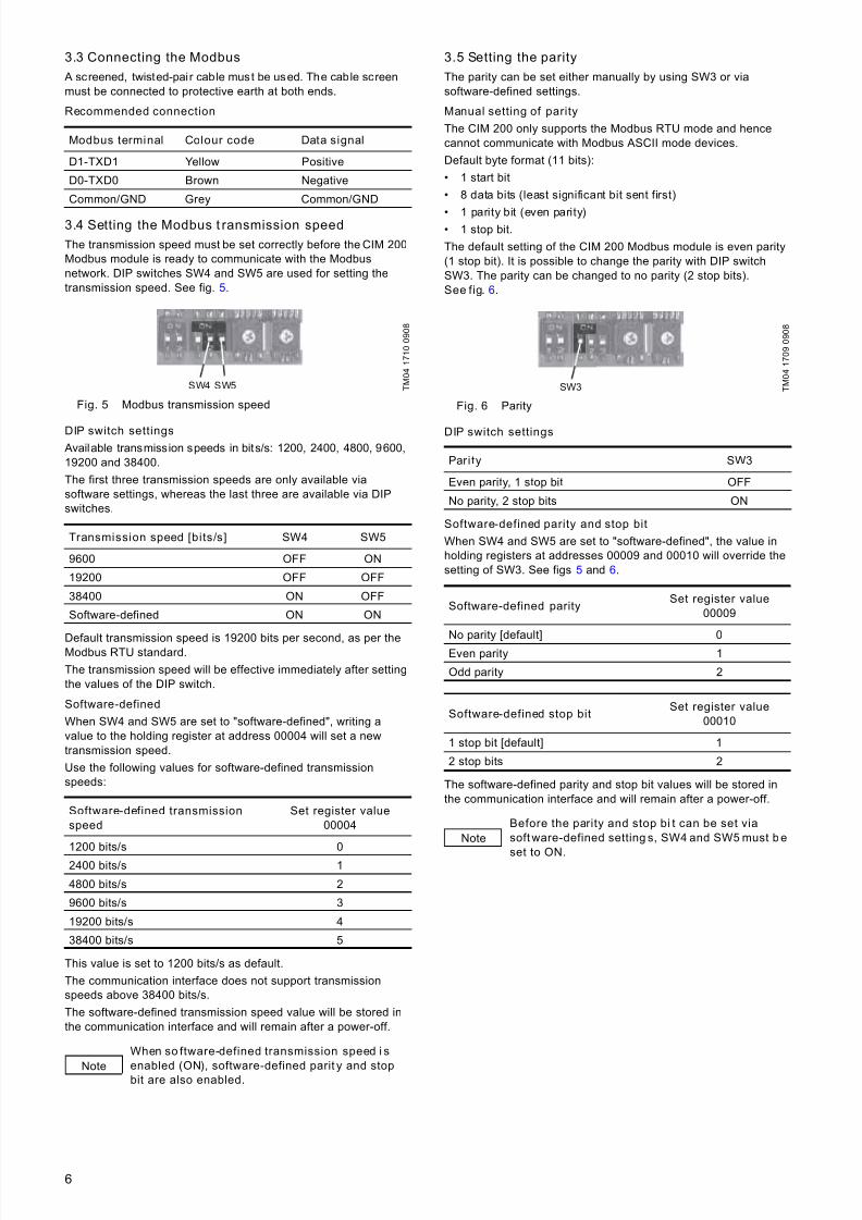
3.4 Setting the Modbus t ransmission speed
The transmission speed must be set correctly before the CIM 200Modbus module is ready to communicate with the Modbusnetwork. DIP switches SW4 and SW5 are used for setting thetransmission speed. See fig. 5.
Fig. 5 Modbus transmission speed
DIP switch settings
Available transmission speeds in bits/s: 1200, 2400, 4800, 9600,19200 and 38400.
The first three transmission speeds are only available viasoftware settings, whereas the last three are available via DIPswitches.
Default transmission speed is 19200 bits per second, as per theModbus RTU standard.
The transmission speed will be effective immediately after settingthe values of the DIP switch.
Software-defined
When SW4 and SW5 are set to "software-defined", writing avalue to the holding register at address 00004 will set a newtransmission speed.
Use the following values for software-defined transmissionspeeds:
This value is set to 1200 bits/s as default.
The communication interface does not support transmissionspeeds above 38400 bits/s.
The software-defined transmission speed value will be stored inthe communication interface and will remain after a power-off.
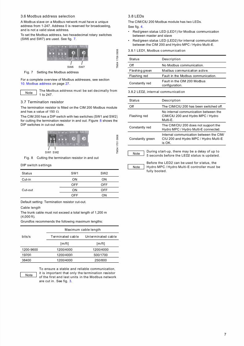
3.5 Setting the parity
The parity can be set either manually by using SW3 or viasoftware-defined settings.
Manual setting of parity
The CIM 200 only supports the Modbus RTU mode and hencecannot communicate with Modbus ASCII mode devices.
Default byte format (11 bits):
• 1 start bit
• 8 data bits (least significant bit sent first)
• 1 parity bit (even parity)• 1 stop bit.
The default setting of the CIM 200 Modbus module is even parity(1 stop bit). It is possible to change the parity with DIP switchSW3. The parity can be changed to no parity (2 stop bits).See fig. 6.
Fig. 6 Parity
DIP switch settings
Software-defined parity and stop bit
When SW4 and SW5 are set to "software-defined", the value inholding registers at addresses 00009 and 00010 will override thesetting of SW3. See figs 5 and 6.
The software-defined parity and stop bit values will be stored inthe communication interface and will remain after a power-off.
Modbus terminal Colour code Data signal
D1-TXD1 Yellow Positive
D0-TXD0 Brown Negative
Common/GND Grey Common/GND
T M 0 4 1 7 1 0 0 9 0 8
Transmission speed [bits/s] SW4 SW5
9600 OFF ON
19200 OFF OFF
38400 ON OFF
Software-defined ON ON
Software-defined transmission
speed
Set register value
00004
1200 bits/s 0
2400 bits/s 1
4800 bits/s 2
9600 bits/s 3
19200 bits/s 4
38400 bits/s 5
Note
When so ftware-defined transmission speed i s
enabled (ON), software-defined parit y and stopbit are also enabled.
SW4 SW5 T M 0 4 1 7 0 9 0 9 0 8
Parity SW3
Even parity, 1 stop bit OFF
No parity, 2 stop bits ON
Software-defined paritySet register value
00009
No parity [default] 0
Even parity 1
Odd parity 2
Software-defined stop bitSet register value
00010
1 stop bit [default] 1
2 stop bits 2
Note
Before the parity and stop bi t can be set via
soft ware-defined setting s, SW4 and SW5 must b e
set to ON.
SW3
7/23/2019 Functional Profile for Modbus CIU 200-MPC
http://slidepdf.com/reader/full/functional-profile-for-modbus-ciu-200-mpc 7/387
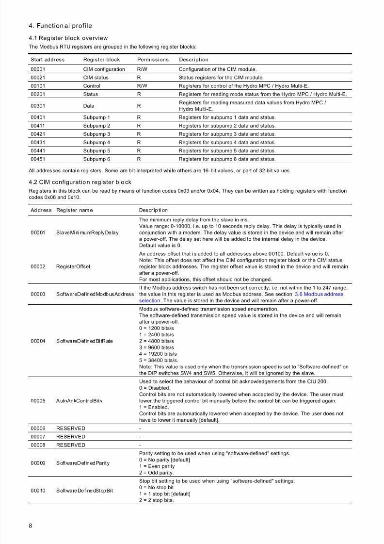
3.6 Modbus address selection
A Modbus slave on a Modbus network must have a uniqueaddress from 1-247. Address 0 is reserved for broadcasting,and is not a valid slave address.
To set the Modbus address, two hexadecimal rotary switches(SW6 and SW7) are used. See fig. 7.
Fig. 7 Setting the Modbus address
For a complete overview of Modbus addresses, see section10. Modbus address on page 27.
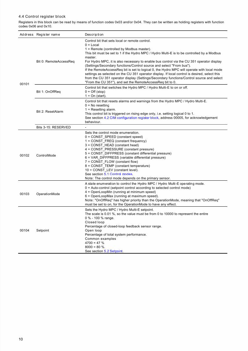
3.7 Termination resistor
The termination resistor is fitted on the CIM 200 Modbus moduleand has a value of 150 Ω.
The CIM 200 has a DIP switch with two switches (SW1 and SW2)
for cutting the termination resistor in and out. Figure 8 shows theDIP switches in cut-out state.
Fig. 8 Cutting the termination resistor in and out
DIP switch s ettings
Default setting: Termination resistor cut-out.
Cable length
The trunk cable must not exceed a total length of 1,200 m(4,000 ft).
Grundfos recommends the following maximum lengths:
3.8 LEDs
The CIM/CIU 200 Modbus module has two LEDs.
See fig. 4.
• Red/green status LED (LED1) for Modbus communicationbetween master and slave
• Red/green status LED (LED2) for internal communicationbetween the CIM 200 and Hydro MPC / Hydro Multi-E.
3.8.1 LED1, Modbus c ommun icati on
3.8.2 LED2, intern al commu nicati on
T M 0 4 1
7 0 6 0 9 0 8
NoteThe Modbus address must be set decimally from
1 to 247.
T M 0 4 1 7 0 1 0 9 0 8
Status SW1 SW2
Cut-in ON ON
Cut-out
OFF OFF
ON OFF
OFF ON
bits/s
Maximum cable length
Terminated cab le Unterminated cab le
[m/ft] [m/ft]
1200-9600 1200/4000 1200/4000
19200 1200/4000 500/1700
38400 1200/4000 250/800
Note
To ensure a stable and reliable communication,
it is important that only the termination resistor
of the first and last units in the Modbus network
are cut in . See fig. 3.
SW6 SW7
SW1 SW2
Status DescriptionOff No Modbus communication.
Flashing green Modbus communication act ive.
Flashing red Fault in the Modbus communication.
Constantly redFault in the CIM 200 Modbusconfiguration.
Status Description
Off The CIM/CIU 200 has been switched off.
Flashing redNo internal communication between theCIM/CIU 200 and Hydro MPC / Hydro
Multi-E.Constantly red
The CIM/CIU 200 does not support theHydro MPC / Hydro Multi-E connected.
Constantly greenInternal communication between the CIM/CIU 200 and Hydro MPC / Hydro Multi-Eis OK.
NoteDuring s tart-up, there may be a delay of up t o
5 seconds before the LED2 status is updated.
Note
Before the LED2 can be used for s tatus, the
Hydro MPC / Hydro Multi-E controller must be
fully booted.
7/23/2019 Functional Profile for Modbus CIU 200-MPC
http://slidepdf.com/reader/full/functional-profile-for-modbus-ciu-200-mpc 8/388
4. Function al profile
4.1 Register block overview
The Modbus RTU registers are grouped in the following register blocks:
All addresses contain registers. Some are bi t-in terpreted whi le others are 16-bit values, or part of 32-bit values.
4.2 CIM configuration register block
Registers in this block can be read by means of function codes 0x03 and/or 0x04. They can be written as holding registers with functioncodes 0x06 and 0x10.
Start address Register block Permissions Description
00001 CIM configuration R/W Configuration of the CIM module.
00021 CIM status R Status registers for the CIM module.
00101 Control R/W Registers for control of the Hydro MPC / Hydro Multi-E.
00201 Status R Registers for reading mode status from the Hydro MPC / Hydro Multi-E.
00301 Data RRegisters for reading measured data values from Hydro MPC /Hydro Multi-E.
00401 Subpump 1 R Registers for subpump 1 data and status.
00411 Subpump 2 R Registers for subpump 2 data and status.
00421 Subpump 3 R Registers for subpump 3 data and status.
00431 Subpump 4 R Registers for subpump 4 data and status.
00441 Subpump 5 R Registers for subpump 5 data and status.
00451 Subpump 6 R Registers for subpump 6 data and status.
Ad dr ess Regis ter nam e Descr ip ti on
00001 SlaveMinimumReplyDelay
The minimum reply delay from the slave in ms.Value range: 0-10000, i.e. up to 10 seconds reply delay. This delay is typically used inconjunction with a modem. The delay value is stored in the device and will remain after a power-off. The delay set here will be added to the internal delay in the device.Default value is 0.
00002 RegisterOffset
An address offset that is added to all addresses above 00100. Defaul t value is 0.Note: This offset does not affect the CIM configuration register block or the CIM statusregister block addresses. The register offset value is stored in the device and will remainafter a power-off.For most applications, this offset should not be changed.
00003 SoftwareDefinedModbusAddressIf the Modbus address switch has not been set correctly, i.e. not within the 1 to 247 range,the value in this register is used as Modbus address. See section 3.6 Modbus address
selection. The value is stored in the device and will remain after a power-off.
00004 SoftwareDef inedBitRate
Modbus software-defined transmission speed enumeration.The software-defined transmission speed value is stored in the device and will remainafter a power-off.0 = 1200 bits/s1 = 2400 bits/s2 = 4800 bits/s3 = 9600 bits/s4 = 19200 bits/s5 = 38400 bits/s.Note: This value is used only when the transmission speed is set to "Software-defined" onthe DIP switches SW4 and SW5. Otherwise, it will be ignored by the slave.
00005 AutoAckControlBits
Used to select the behaviour of control bit acknowledgements from the CIU 200.0 = Disabled.Control bits are not automatically lowered when accepted by the device. The user mustlower the triggered control bit manually before the control bit can be triggered again.1 = Enabled.Control bits are automatically lowered when accepted by the device. The user does nothave to lower it manually [default].
00006 RESERVED -
00007 RESERVED -
00008 RESERVED -
00009 SoftwareDef inedParity
Parity setting to be used when using "software-defined" settings.0 = No parity [default]1 = Even parity2 = Odd parity.
00010 SoftwareDefinedStopBit
Stop bit setting to be used when using "software-defined" settings.0 = No stop bit1 = 1 stop bit [default]2 = 2 stop bits.

7/23/2019 Functional Profile for Modbus CIU 200-MPC
http://slidepdf.com/reader/full/functional-profile-for-modbus-ciu-200-mpc 9/389
4.3 CIM status register block
Registers in this block can be read by means of function codes 0x03 and/or 0x04. They are read-only. This block can be used for variouskinds of fault finding.
Ad dr ess Regis ter nam e Descr ip ti on
00021 GENIbusCRCErrorCnt Holds a CRC error counter for the GENIbus connection to the Hydro MPC / Hydro Multi-E.
00022 GENIbusDataErrorCnt Holds a data error counter for the GENIbus connection to the Hydro MPC / Hydro Multi-E.
00023 VersionNumber A Grundfos-specific version number. This is an unsigned integer value.
00024 ActualModbusAddressHolds the current Modbus slave address of the device.
Valid value range: 1…247.0002500026
GENIbusTXcountHIGENIbusTXcountLO
Holds a transmit counter for total number of telegrams sent to the Hydro MPC / Hydro Multi-Eon the GENIbus connection.
0002700028
GENIbusRXcountHIGENIbusRXcountLO
Holds a receive counter for total number of telegrams received from the Hydro MPC /Hydro Multi-E on the GENIbus connection.
00029 RESERVED -
00030 UnitFamily Grundfos product family.
00031 UnitType Grundfos product type.
00032 UnitVersion Grundfos product version.
7/23/2019 Functional Profile for Modbus CIU 200-MPC
http://slidepdf.com/reader/full/functional-profile-for-modbus-ciu-200-mpc 10/3810
4.4 Control register bl ock
Registers in this block can be read by means of function codes 0x03 and/or 0x04. They can be written as holding registers with functioncodes 0x06 and 0x10.
Ad dr ess Regis ter nam e Descr ip ti on
00101
Bit 0: RemoteAccessReq
Control bit that sets local or remote control.0 = Local1 = Remote (controlled by Modbus master).This bit must be set to 1 if the Hydro MPC / Hydro Multi-E is to be controlled by a Modbusmaster.
For Hydro MPC, it is also necessary to enable bus control via the CU 351 operator display(Settings/Secondary functions/Control source and select "From bus").If the RemoteAccessReq bit is set to logical 0, the Hydro MPC will operate with local modesettings as selected on the CU 351 operator display. If local control is desired, select thisfrom the CU 351 operator display (Settings/Secondary functions/Control source and select"From the CU 351"), and set the RemoteAccessReq bit to 0.
Bit 1: OnOffReqControl bit that switches the Hydro MPC / Hydro Multi-E to on or off.0 = Off (stop)1 = On (start).
Bit 2: ResetAlarm
Control bit that resets alarms and warnings from the Hydro MPC / Hydro Multi-E.0 = No resetting1 = Resetting alarm.This control bit is triggered on rising edge only, i.e. setting logical 0 to 1.See section 4.2 CIM configuration register block, address 00005, for acknowledgement
behaviour.Bits 3-15: RESERVED -
00102 ControlMode
Sets the control mode enumeration.0 = CONST_SPEED (constant speed)1 = CONST_FREQ (constant frequency)3 = CONST_HEAD (constant head)4 = CONST_PRESSURE (constant pressure)5 = CONST_DIFFPRESS (constant differential pressure)6 = VAR_DIFFPRESS (variable differential pressure)7 = CONST_FLOW (constant flow)8 = CONST_TEMP (constant temperature)10 = CONST_LEV (constant level).See section 5.1 Control modes.Note: The control mode depends on the primary sensor.
00103 OperationMode
A state enumeration to contro l the Hydro MPC / Hydro Multi -E operating mode.0 = Auto-control (setpoint control according to selected control mode)4 = OpenLoopMin (running at minimum speed)6 = OpenLoopMax (running at maximum speed).Note: "OnOffReq" has higher priority than the OperationMode, meaning that "OnOffReq"must be set to on, for the OperationMode to have any effect.
00104 Setpoint
Sets the Hydro MPC / Hydro Multi-E setpoint.The scale is 0.01 %, so the value must be from 0 to 10000 to represent the entire0 % - 100 % range.Closed loop
Percentage of closed-loop feedback sensor range.Open loop
Percentage of total system performance.Common examples
4700 = 47 %
8000 = 80 %.See section 5.2 Setpoint.
7/23/2019 Functional Profile for Modbus CIU 200-MPC
http://slidepdf.com/reader/full/functional-profile-for-modbus-ciu-200-mpc 11/3811
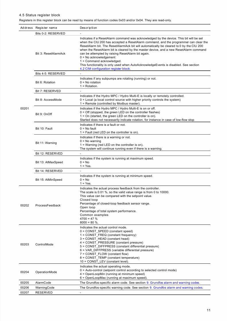
4.5 Status register block
Registers in this register block can be read by means of function codes 0x03 and/or 0x04. They are read-only.
Ad dr ess Regis ter nam e Descr ip ti on
00201
Bits 0-2: RESERVED -
Bit 3: ResetAlarmAck
Indicates if a ResetAlarm command was acknowledged by the device. This bit will be setwhen the CIU 200 has accepted a ResetAlarm command, and the programmer can clear theResetAlarm bit. The ResetAlarmAck bit will automatically be cleared to 0 by the CIU 200when the ResetAlarm bit is cleared by the master device, and a new ResetAlarm commandcan be attempted by raising ResetAlarm bit again.
0 = No acknowledgement1 = Command acknowledged.This functionality is only used when AutoAcknowledgeEvents is disabled. See section4.2 CIM configuration register block.
Bits 4-5: RESERVED -
Bit 6: RotationIndicates if any subpumps are rotating (running) or not.0 = No rotation1 = Rotation.
Bit 7: RESERVED -
Bit 8: AccessModeIndicates if the Hydro MPC / Hydro Multi-E is locally or remotely controlled.0 = Local (a local control source with higher priority controls the system)1 = Remote (controlled by Modbus master).
Bit 9: OnOff
Indicates if the Hydro MPC / Hydro Multi-E is on or off.
0 = Off (stopped, the green LED on the controller flashes)1 = On (started, the green LED on the controller is on).Started does not necessarily indicate rotation, for instance in case of low-flow stop.
Bit 10: FaultIndicates if there is a fault or not.0 = No fault1 = Fault (red LED on the controller is on).
Bit 11: Warning
Indicates if there is a warning or not.0 = No warning1 = Warning (red LED on the controller is on).The system will continue running even if there is a warning.
Bit 12: RESERVED -
Bit 13: AtMaxSpeedIndicates if the system is running at maximum speed.0 = No1 = Yes.
Bit 14: RESERVED -
Bit 15: AtMinSpeedIndicates if the system is running at minimum speed.0 = No1 = Yes.
00202 ProcessFeedback
Indicates the actual process feedback from the controller.The scale is 0.01 %, so the valid value range is from 0 to 10000.This value can be compared with the setpoint value.Closed loop
Percentage of closed-loop feedback sensor range.Open loop
Percentage of total system performance.Common examples
4700 = 47 %8000 = 80 %.
00203 ControlMode
Indicates the actual control mode.0 = CONST_SPEED (constant speed)1 = CONST_FREQ (constant frequency)3 = CONST_HEAD (constant head)4 = CONST_PRESSURE (constant pressure)5 = CONST_DIFFPRESS (constant differential pressure)6 = VAR_DIFFPRESS (variable differential pressure)7 = CONST_FLOW (constant flow)8 = CONST_TEMP (constant temperature)10 = CONST_LEV (constant level).
00204 OperationMode
Indicates the actual operating mode.0 = Auto-control (setpoint control according to selected control mode)4 = OpenLoopMin (running at minimum speed)6 = OpenLoopMax (running at maximum speed).
00205 AlarmCode The Grundfos-specific alarm code. See section 9. Grundfos alarm and warning codes.
00206 WarningCode The Grundfos-specific warning code. See section 9. Grundfos alarm and warning codes.
00207 RESERVED -
7/23/2019 Functional Profile for Modbus CIU 200-MPC
http://slidepdf.com/reader/full/functional-profile-for-modbus-ciu-200-mpc 12/3812
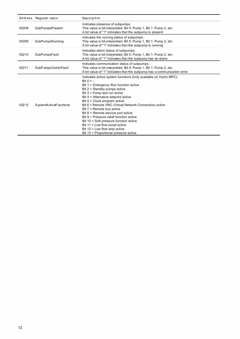
00208 SubPumpsPresentIndicates presence of subpumps.This value is bit-interpreted: Bit 0: Pump 1, Bit 1: Pump 2, etc.
A bit value of "1" indicates that the subpump is present.
00209 SubPumpsRunningIndicates the running status of subpumps.This value is bit-interpreted: Bit 0: Pump 1, Bit 1: Pump 2, etc.
A bit value of "1" indicates that the subpump is running.
00210 SubPumpsFaultIndicates alarm status of subpumps.This value is bit-interpreted: Bit 0: Pump 1, Bit 1: Pump 2, etc.
A bit value of "1" indicates that the subpump has an alarm.
00211 SubPumpsCommFaul tIndicates communication status of subpumps.This value is bit-interpreted: Bit 0: Pump 1, Bit 1: Pump 2, etc.
A bit value of "1" indicates that the subpump has a communication error.
00212 SystemAct iveFunct ions
Indicates active system functions (only available on Hydro MPC):Bit 0 = -Bit 1 = Emergency Run function activeBit 2 = Standby pumps activeBit 3 = Pump test run activeBit 4 = Alternative setpoint activeBit 5 = Clock program activeBit 6 = Remote VNC (Virtual Network Connection) activeBit 7 = Remote bus activeBit 8 = Remote service port activeBit 9 = Pressure relief function activeBit 10 = Soft pressure function activeBit 11 = Low flow boost activeBit 12 = Low flow stop activeBit 13 = Proportional pressure active.
Ad dr ess Regis ter nam e Descr ip ti on
7/23/2019 Functional Profile for Modbus CIU 200-MPC
http://slidepdf.com/reader/full/functional-profile-for-modbus-ciu-200-mpc 13/3813
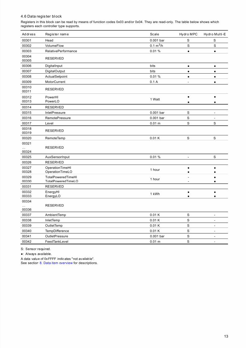
4.6 Data regis ter block
Registers in this block can be read by means of function codes 0x03 and/or 0x04. They are read-only. The table below shows whichregisters each controller type supports.
S: Sensor required.
●: Always available.
A data value of 0xFFFF indicates "not available".See section 8. Data item overview for descriptions.
Ad dr ess Reg is ter nam e Scale Hydr o MPC Hydr o Mul ti -E
00301 Head 0.001 bar S S
00302 VolumeFlow 0.1 m3/h S S
00303 RelativePerformance 0.01 % ● ●
00304
00305RESERVED
00306 DigitalInput bits ● ●
00307 DigitalOutput bits ● ●
00308 ActualSetpoint 0.01 % ● ●
00309 MotorCurrent 0.1 A - ●
0031000311
RESERVED
0031200313
PowerHIPowerLO
1 Watt● ●
● ●
00314 RESERVED
00315 InletPressure 0.001 bar S -
00316 RemotePressure 0.001 bar S -
00317 Level 0.01 m S S
0031800319
RESERVED
00320 RemoteTemp 0.01 K S S
00321…00324
RESERVED
00325 AuxSensorInput 0.01 % - S
00326 RESERVED
0032700328
OperationTimeHIOperationTimeLO
1 hour ●
●
●
●
00329
00330
TotalPoweredTimeHI
TotalPoweredTimeLO
1 hour -
-
●
●
00331 RESERVED
0033200333
EnergyHIEnergyLO
1 kWh ●
●
●
●
00334…00336
RESERVED
00337 AmbientTemp 0.01 K S -
00338 InletTemp 0.01 K S -
00339 OutletTemp 0.01 K S -
00340 TempDifference 0.01 K S -
00341 OutletPressure 0.001 bar S -
00342 FeedTankLevel 0.01 m S -
7/23/2019 Functional Profile for Modbus CIU 200-MPC
http://slidepdf.com/reader/full/functional-profile-for-modbus-ciu-200-mpc 14/3814
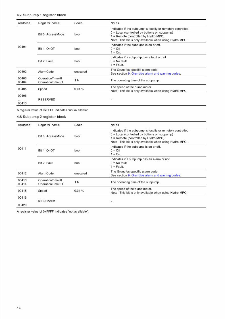
4.7 Subpump 1 register block
A register value of 0xFFFF indicates "not available".
4.8 Subpump 2 register block
A register value of 0xFFFF indicates "not available".
Ad dr ess Regis ter nam e Scale Not es
00401
Bit 0: AccessMode bool
Indicates if the subpump is locally or remotely controlled.0 = Local (controlled by buttons on subpump)1 = Remote (controlled by Hydro MPC).Note: This bit is only available when using Hydro MPC.
Bit 1: OnOff boolIndicates if the subpump is on or off.0 = Off 1 = On.
Bit 2: Fault boolIndicates if a subpump has a fault or not.0 = No fault1 = Fault.
00402 AlarmCode unscaledThe Grundfos-specific alarm code.See section 9. Grundfos alarm and warning codes.
0040300404
OperationTimeHIOperationTimeLO
1 h The operating time of the subpump.
00405 Speed 0.01 %The speed of the pump motor.Note: This bit is only available when using Hydro MPC.
00406...00410
RESERVED -
Ad dr ess Regis ter nam e Scale Not es
00411
Bit 0: AccessMode bool
Indicates if the subpump is locally or remotely controlled.0 = Local (controlled by buttons on subpump)1 = Remote (controlled by Hydro MPC).Note: This bit is only available when using Hydro MPC.
Bit 1: OnOff boolIndicates if the subpump is on or off.0 = Off 1 = On.
Bit 2: Fault boolIndicates if a subpump has an alarm or not.0 = No fault
1 = Fault.00412 AlarmCode unscaled
The Grundfos-specific alarm code.See section 9. Grundfos alarm and warning codes.
0041300414
OperationTimeHIOperationTimeLO
1 h The operating time of the subpump.
00415 Speed 0.01 %The speed of the pump motor.Note: This bit is only available when using Hydro MPC.
00416...00420
RESERVED -
7/23/2019 Functional Profile for Modbus CIU 200-MPC
http://slidepdf.com/reader/full/functional-profile-for-modbus-ciu-200-mpc 15/3815
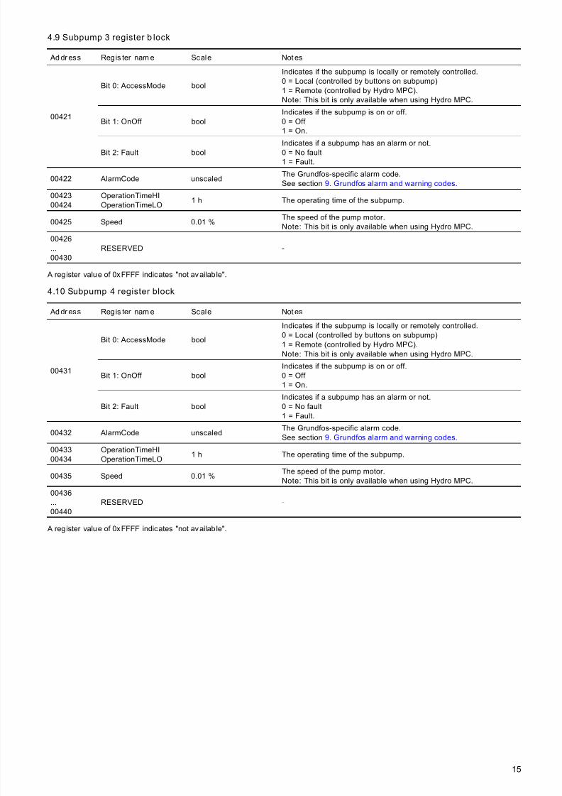
4.9 Subpump 3 register b lock
A register value of 0xFFFF indicates "not available".
4.10 Subpump 4 register block
A register value of 0xFFFF indicates "not available".
Ad dr ess Regis ter nam e Scale Not es
00421
Bit 0: AccessMode bool
Indicates if the subpump is locally or remotely controlled.0 = Local (controlled by buttons on subpump)1 = Remote (controlled by Hydro MPC).Note: This bit is only available when using Hydro MPC.
Bit 1: OnOff boolIndicates if the subpump is on or off.0 = Off 1 = On.
Bit 2: Fault boolIndicates if a subpump has an alarm or not.0 = No fault1 = Fault.
00422 AlarmCode unscaledThe Grundfos-specific alarm code.See section 9. Grundfos alarm and warning codes.
0042300424
OperationTimeHIOperationTimeLO
1 h The operating time of the subpump.
00425 Speed 0.01 %The speed of the pump motor.Note: This bit is only available when using Hydro MPC.
00426...00430
RESERVED -
Ad dr ess Regis ter nam e Scale Not es
00431
Bit 0: AccessMode bool
Indicates if the subpump is locally or remotely controlled.0 = Local (controlled by buttons on subpump)1 = Remote (controlled by Hydro MPC).Note: This bit is only available when using Hydro MPC.
Bit 1: OnOff boolIndicates if the subpump is on or off.0 = Off 1 = On.
Bit 2: Fault boolIndicates if a subpump has an alarm or not.0 = No fault
1 = Fault.00432 AlarmCode unscaled
The Grundfos-specific alarm code.See section 9. Grundfos alarm and warning codes.
0043300434
OperationTimeHIOperationTimeLO
1 h The operating time of the subpump.
00435 Speed 0.01 %The speed of the pump motor.Note: This bit is only available when using Hydro MPC.
00436...00440
RESERVED -

7/23/2019 Functional Profile for Modbus CIU 200-MPC
http://slidepdf.com/reader/full/functional-profile-for-modbus-ciu-200-mpc 16/3816
4.11 Subpump 5 register block
A register value of 0xFFFF indicates "not available".
4.12 Subpump 6 register block
A register value of 0xFFFF indicates "not available".
Ad dr ess Regis ter nam e Scale Not es
00441
Bit 0: AccessMode bool
Indicates if the subpump is locally or remotely controlled.0 = Local (controlled by buttons on subpump)1 = Remote (controlled by Hydro MPC).Note: This bit is only available when using Hydro MPC.
Bit 1: OnOff boolIndicates if the subpump is on or off.0 = Off 1 = On.
Bit 2: Fault boolIndicates if a subpump has an alarm or not.0 = No fault1 = Fault.
00442 AlarmCode unscaledThe Grundfos-specific alarm code.See section 9. Grundfos alarm and warning codes.
0044300444
OperationTimeHIOperationTimeLO
1 h The operating time of the subpump.
00445 Speed 0.01 %The speed of the pump motor.Note: This bit is only available when using Hydro MPC.
00446...00450
RESERVED -
Ad dr ess Regis ter nam e Scale Not es
00451
Bit 0: AccessMode bool
Indicates if the subpump is locally or remotely controlled.0 = Local (controlled by buttons on subpump)1 = Remote (controlled by Hydro MPC).Note: This bit is only available when using Hydro MPC.
Bit 1: OnOff boolIndicates if the subpump is on or off.0 = Off 1 = On.
Bit 2: Fault boolIndicates if a subpump has an alarm or not.0 = No fault
1 = Fault.00452 AlarmCode unscaled
The Grundfos-specific alarm code.See section 9. Grundfos alarm and warning codes.
0045300454
OperationTimeHIOperationTimeLO
1 h The operating time of the subpump.
00455 Speed 0.01 %The speed of the pump motor.Note: This bit is only available when using Hydro MPC.
00456...00460
RESERVED -
7/23/2019 Functional Profile for Modbus CIU 200-MPC
http://slidepdf.com/reader/full/functional-profile-for-modbus-ciu-200-mpc 17/3817
5. Detailed descr ipti ons
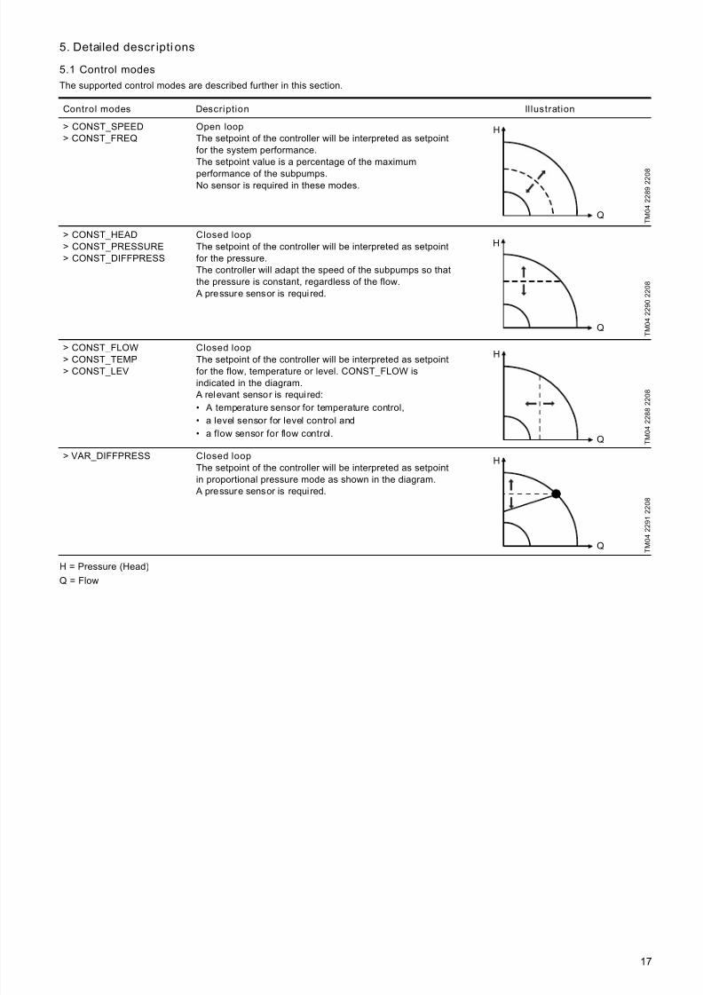
5.1 Control modes
The supported control modes are described further in this section.
H = Pressure (Head)
Q = Flow
Control modes Description Illustration
> CONST_SPEED> CONST_FREQ
Open loop
The setpoint of the controller will be interpreted as setpointfor the system performance.The setpoint value is a percentage of the maximum
performance of the subpumps.No sensor is required in these modes.
T M 0 4 2 2 8 9 2 2 0
8
> CONST_HEAD> CONST_PRESSURE> CONST_DIFFPRESS
Closed loop
The setpoint of the controller will be interpreted as setpointfor the pressure.The controller will adapt the speed of the subpumps so thatthe pressure is constant, regardless of the flow.
A pressure sensor is requi red.
T M 0 4 2 2 9 0 2 2 0 8
> CONST_FLOW> CONST_TEMP> CONST_LEV
Closed loopThe setpoint of the controller will be interpreted as setpointfor the flow, temperature or level. CONST_FLOW isindicated in the diagram.
A relevant sensor is required:
• A temperature sensor for temperature control,• a level sensor for level control and
• a flow sensor for flow control. T M 0 4 2 2 8 8 2 2 0 8
> VAR_DIFFPRESS Closed loop
The setpoint of the controller will be interpreted as setpointin proportional pressure mode as shown in the diagram.
A pressure sensor is required.
T M 0 4 2 2 9
1 2 2 0 8
H
Q
H
Q
H
Q
H
Q
7/23/2019 Functional Profile for Modbus CIU 200-MPC
http://slidepdf.com/reader/full/functional-profile-for-modbus-ciu-200-mpc 18/3818
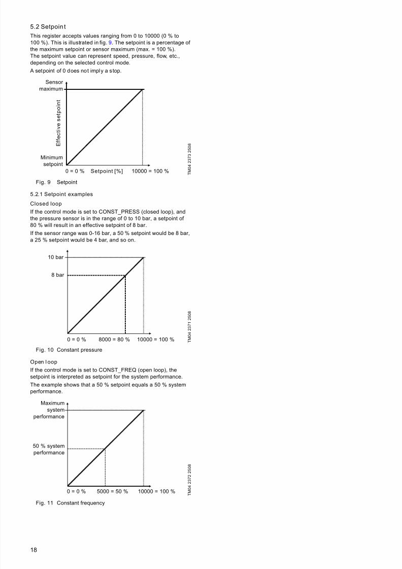
5.2 Setpoin t
This register accepts values ranging from 0 to 10000 (0 % to100 %). This is illustrated in fig. 9. The setpoint is a percentage of the maximum setpoint or sensor maximum (max. = 100 %).The setpoint value can represent speed, pressure, flow, etc.,depending on the selected control mode.
A setpoint of 0 does not imply a stop.
Fig. 9 Setpoint
5.2.1 Setpoint examples
Closed loop
If the control mode is set to CONST_PRESS (closed loop), andthe pressure sensor is in the range of 0 to 10 bar, a setpoint of 80 % will result in an effective setpoint of 8 bar.
If the sensor range was 0-16 bar, a 50 % setpoint would be 8 bar,a 25 % setpoint would be 4 bar, and so on.
Fig. 10 Constant pressure
Open l oop
If the control mode is set to CONST_FREQ (open loop), thesetpoint is interpreted as setpoint for the system performance.
The example shows that a 50 % setpoint equals a 50 % systemperformance.
Fig. 11 Constant frequency
T M 0 4 2 3 7 3 2 5 0 8
T M 0 4 2 3 7 1 2 5 0 8
T M 0 4 2 3 7 2 2 5 0 8
Sensor maximum
Minimumsetpoint
E f f e c t i v e
s e t p o i n t
0 = 0 % 10000 = 100 %Setpoint [%]
10 bar
8 bar
0 = 0 % 10000 = 100 %8000 = 80 %
Maximumsystem
performance
50 % systemperformance
0 = 0 % 10000 = 100 %5000 = 50 %
7/23/2019 Functional Profile for Modbus CIU 200-MPC
http://slidepdf.com/reader/full/functional-profile-for-modbus-ciu-200-mpc 19/3819
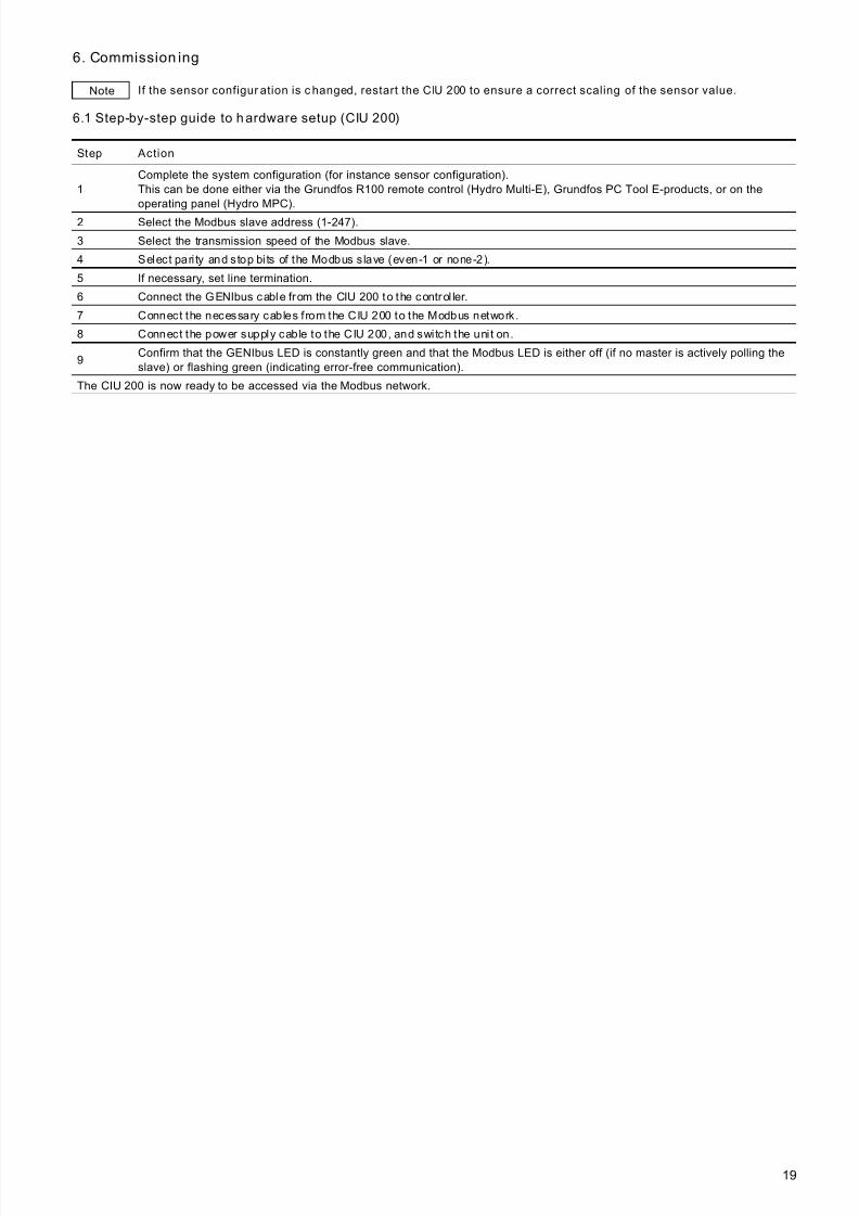
6. Commission ing
6.1 Step-by-step guide to hardware setup (CIU 200)
Note If the sensor configur ation is c hanged, restart the CIU 200 to ensure a correct scaling of the sensor value.
Step Action
1Complete the system configuration (for instance sensor configuration).This can be done either via the Grundfos R100 remote control (Hydro Multi-E), Grundfos PC Tool E-products, or on theoperating panel (Hydro MPC).
2 Select the Modbus slave address (1-247).
3 Select the transmission speed of the Modbus slave.
4 Select pari ty and stop bits of the Modbus slave (even-1 or none-2).
5 If necessary, set line termination.
6 Connect the GENIbus cable from the CIU 200 to the control ler.
7 Connect the necessary cables f rom the CIU 200 to the Modbus network.
8 Connect the power supply cable to the CIU 200, and switch the unit on.
9Confirm that the GENIbus LED is constantly green and that the Modbus LED is either off (if no master is actively polling theslave) or flashing green (indicating error-free communication).
The CIU 200 is now ready to be accessed via the Modbus network.
7/23/2019 Functional Profile for Modbus CIU 200-MPC
http://slidepdf.com/reader/full/functional-profile-for-modbus-ciu-200-mpc 20/3820
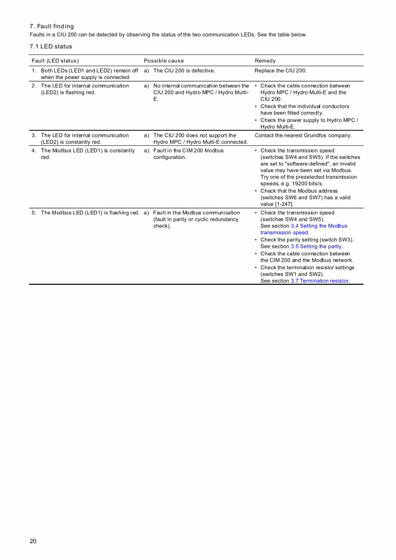
7. Fault find ing
Faults in a CIU 200 can be detected by observing the status of the two communication LEDs. See the table below.
7.1 LED status
Fault (LED status) Possible cause Remedy
1. Both LEDs (LED1 and LED2) remain off when the power supply is connected.
a) The CIU 200 is defective. Replace the CIU 200.
2. The LED for internal communication(LED2) is flashing red.
a) No internal communication between theCIU 200 and Hydro MPC / Hydro Multi-
E.
• Check the cable connection betweenHydro MPC / Hydro Multi-E and the
CIU 200.• Check that the individual conductors
have been fitted correctly.
• Check the power supply to Hydro MPC /Hydro Multi-E.
3. The LED for internal communication(LED2) is constantly red.
a) The CIU 200 does not support theHydro MPC / Hydro Multi-E connected.
Contact the nearest Grundfos company.
4. The Modbus LED (LED1) is constantlyred.
a) Fault in the CIM 200 Modbusconfiguration.
• Check the transmission speed(switches SW4 and SW5). If the switchesare set to "software-defined", an invalidvalue may have been set via Modbus.Try one of the preselected transmissionspeeds, e.g. 19200 bits/s.
• Check that the Modbus address
(switches SW6 and SW7) has a validvalue [1-247].
5. The Modbus LED (LED1) is flashing red. a) Fault in the Modbus communication(fault in parity or cyclic redundancycheck).
• Check the transmission speed(switches SW4 and SW5).See section 3.4 Setting the Modbus
transmission speed.• Check the parity setting (switch SW3).
See section 3.5 Setting the parity.
• Check the cable connection betweenthe CIM 200 and the Modbus network.
• Check the termination resistor settings(switches SW1 and SW2).See section 3.7 Termination resistor .
7/23/2019 Functional Profile for Modbus CIU 200-MPC
http://slidepdf.com/reader/full/functional-profile-for-modbus-ciu-200-mpc 21/3821
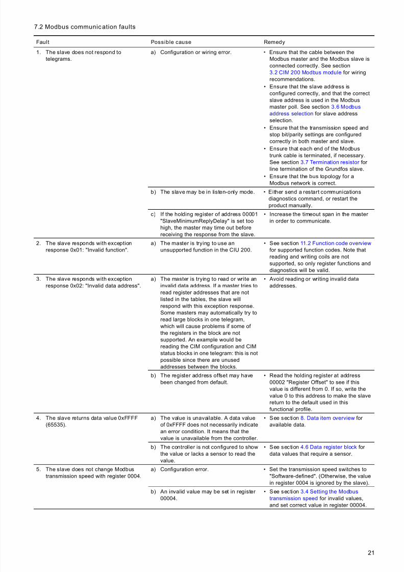
7.2 Modbus communic ation faults
Fault Possible cause Remedy
1. The slave does not respond totelegrams.
a) Configuration or wiring error. • Ensure that the cable between theModbus master and the Modbus slave isconnected correctly. See section3.2 CIM 200 Modbus module for wiringrecommendations.
• Ensure that the slave address isconfigured correctly, and that the correct
slave address is used in the Modbusmaster poll. See section 3.6 Modbus
address selection for slave addressselection.
• Ensure that the transmission speed andstop bit/parity settings are configuredcorrectly in both master and slave.
• Ensure that each end of the Modbustrunk cable is terminated, if necessary.See section 3.7 Termination resistor for line termination of the Grundfos slave.
• Ensure that the bus topology for aModbus network is correct.
b) The slave may be in listen-only mode. • Either send a restart communications
diagnostics command, or restart theproduct manually.
c) If the holding register of address 00001"SlaveMinimumReplyDelay" is set toohigh, the master may time out beforereceiving the response from the slave.
• Increase the timeout span in the master in order to communicate.
2. The slave responds with exceptionresponse 0x01: "Invalid function".
a) The master is trying to use anunsupported function in the CIU 200.
• See section 11.2 Function code overview for supported function codes. Note thatreading and writing coils are notsupported, so only register functions anddiagnostics will be valid.
3. The slave responds with exceptionresponse 0x02: "Invalid data address".
a) The master is trying to read or write aninvalid data address. If a master tries toread register addresses that are not
listed in the tables, the slave willrespond with this exception response.Some masters may automatically try toread large blocks in one telegram,which will cause problems if some of the registers in the block are notsupported. An example would bereading the CIM configuration and CIMstatus blocks in one telegram: this is notpossible since there are unusedaddresses between the blocks.
• Avoid reading or writing invalid dataaddresses.
b) The register address offset may havebeen changed from default.
• Read the holding register at address00002 "Register Offset" to see if thisvalue is different from 0. If so, write thevalue 0 to this address to make the slave
return to the default used in thisfunctional profile.
4. The slave returns data value 0xFFFF(65535).
a) The value is unavailable. A data valueof 0xFFFF does not necessarily indicatean error condition. It means that thevalue is unavailable from the controller.
• See section 8. Data item overview for available data.
b) The controller is not configured to showthe value or lacks a sensor to read thevalue.
• See section 4.6 Data register block for data values that require a sensor.
5. The slave does not change Modbustransmission speed with register 0004.
a) Configuration error. • Set the transmission speed switches to"Software-defined". (Otherwise, the valuein register 0004 is ignored by the slave).
b) An invalid value may be set in register
00004.
• See section 3.4 Setting the Modbus
transmission speed for invalid values,and set correct value in register 00004.
7/23/2019 Functional Profile for Modbus CIU 200-MPC
http://slidepdf.com/reader/full/functional-profile-for-modbus-ciu-200-mpc 22/3822
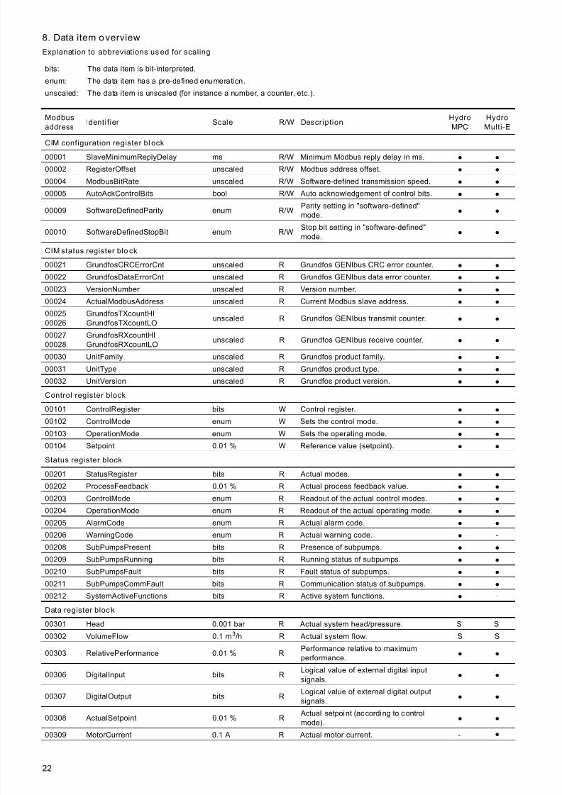
8. Data item overview
Explanation to abbreviations us ed for scaling
bits: The data item is bit-interpreted.
enum: The data item has a pre-defined enumeration.
unscaled: The data item is unscaled (for instance a number, a counter, etc.).
Modbus
addressIdenti fier Scale R/W Description
Hydro
MPC
Hydro
Multi-E
CIM configuration register bl ock
00001 SlaveMinimumReplyDelay ms R/W Minimum Modbus reply delay in ms. ● ●
00002 RegisterOffset unscaled R/W Modbus address offset. ● ●
00004 ModbusBitRate unscaled R/W Software-defined transmission speed. ● ●
00005 AutoAckControlBits bool R/W Auto acknowledgement of control bits. ● ●
00009 SoftwareDefinedParity enum R/WParity setting in "software-defined"mode. ● ●
00010 SoftwareDefinedStopBit enum R/WStop bit setting in "software-defined"mode. ● ●
CIM status register blo ck
00021 GrundfosCRCErrorCnt unscaled R Grundfos GENIbus CRC error counter. ● ●
00022 GrundfosDataErrorCnt unscaled R Grundfos GENIbus data error counter. ● ●
00023 VersionNumber unscaled R Version number. ● ●
00024 ActualModbusAddress unscaled R Current Modbus slave address. ● ●
0002500026
GrundfosTXcountHIGrundfosTXcountLO
unscaled R Grundfos GENIbus transmit counter. ● ●
0002700028
GrundfosRXcountHIGrundfosRXcountLO
unscaled R Grundfos GENIbus receive counter. ● ●
00030 UnitFamily unscaled R Grundfos product family. ● ●
00031 UnitType unscaled R Grundfos product type. ● ●
00032 UnitVersion unscaled R Grundfos product version. ● ●
Control register block
00101 ControlRegister bits W Control register. ● ●
00102 ControlMode enum W Sets the control mode. ● ●
00103 OperationMode enum W Sets the operating mode. ● ●
00104 Setpoint 0.01 % W Reference value (setpoint). ● ●
Status register block
00201 StatusRegister bits R Actual modes. ● ●
00202 ProcessFeedback 0.01 % R Actual process feedback value. ● ●
00203 ControlMode enum R Readout of the actual control modes. ● ●
00204 OperationMode enum R Readout of the actual operating mode. ● ●
00205 AlarmCode enum R Actual alarm code. ● ●
00206 WarningCode enum R Actual warning code. ● -
00208 SubPumpsPresent bits R Presence of subpumps. ● ●
00209 SubPumpsRunning bits R Running status of subpumps. ● ●
00210 SubPumpsFault bits R Fault status of subpumps. ● ●
00211 SubPumpsCommFault bits R Communication status of subpumps. ● ●
00212 SystemActiveFunctions bits R Active system functions. ● -
Data register bloc k
00301 Head 0.001 bar R Actual system head/pressure. S S
00302 VolumeFlow 0.1 m3/h R Actual system flow. S S
00303 RelativePerformance 0.01 % RPerformance relative to maximumperformance. ● ●
00306 DigitalInput bits RLogical value of external digital inputsignals. ● ●
00307 DigitalOutput bits RLogical value of external digital outputsignals. ● ●
00308 ActualSetpoint 0.01 % R Actual setpoint (according to controlmode). ● ●
00309 MotorCurrent 0.1 A R Actual motor current. - ●
7/23/2019 Functional Profile for Modbus CIU 200-MPC
http://slidepdf.com/reader/full/functional-profile-for-modbus-ciu-200-mpc 23/3823
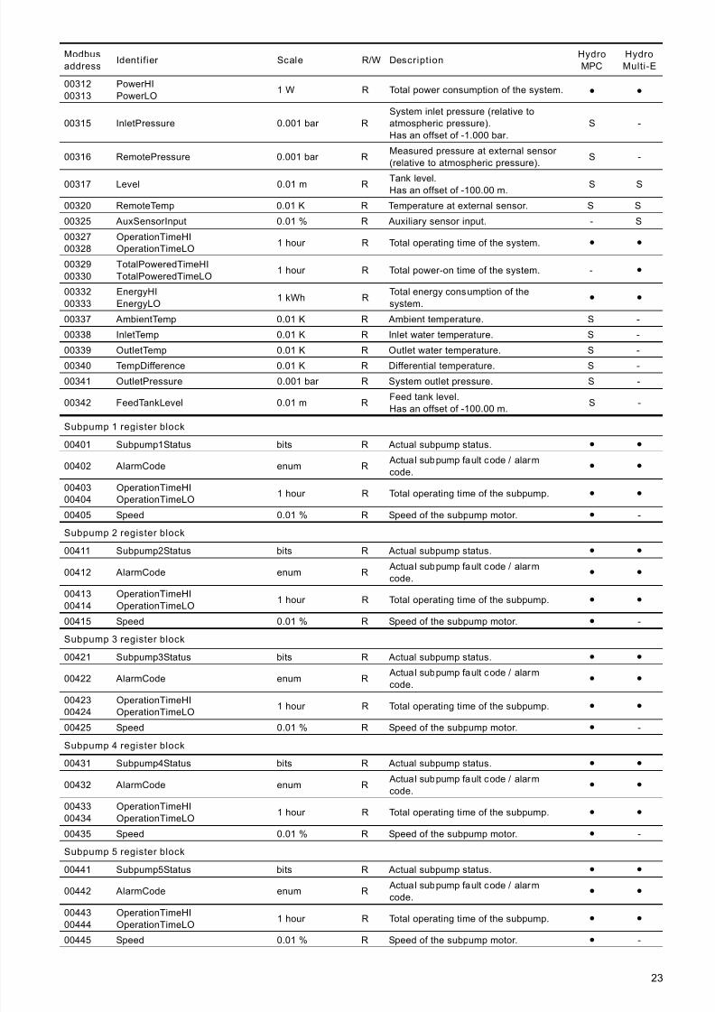
0031200313
PowerHIPowerLO
1 W R Total power consumption of the system. ● ●
00315 InletPressure 0.001 bar RSystem inlet pressure (relative toatmospheric pressure).Has an offset of -1.000 bar.
S -
00316 RemotePressure 0.001 bar RMeasured pressure at external sensor (relative to atmospheric pressure).
S -
00317 Level 0.01 m R Tank level.Has an offset of -100.00 m.
S S
00320 RemoteTemp 0.01 K R Temperature at external sensor. S S
00325 AuxSensorInput 0.01 % R Auxiliary sensor input. - S
0032700328
OperationTimeHIOperationTimeLO
1 hour R Total operating time of the system. ● ●
0032900330
TotalPoweredTimeHITotalPoweredTimeLO
1 hour R Total power-on time of the system. - ●
0033200333
EnergyHIEnergyLO
1 kWh RTotal energy consumption of thesystem.
● ●
00337 AmbientTemp 0.01 K R Ambient temperature. S -
00338 InletTemp 0.01 K R Inlet water temperature. S -
00339 OutletTemp 0.01 K R Outlet water temperature. S -00340 TempDifference 0.01 K R Differential temperature. S -
00341 OutletPressure 0.001 bar R System outlet pressure. S -
00342 FeedTankLevel 0.01 m RFeed tank level.Has an offset of -100.00 m.
S -
Subpump 1 register block
00401 Subpump1Status bits R Actual subpump status. ● ●
00402 AlarmCode enum R Actual subpump fault code / alarmcode.
● ●
0040300404
OperationTimeHIOperationTimeLO
1 hour R Total operating time of the subpump. ● ●
00405 Speed 0.01 % R Speed of the subpump motor. ● -
Subpump 2 register block
00411 Subpump2Status bits R Actual subpump status. ● ●
00412 AlarmCode enum R Actual subpump fault code / alarmcode.
● ●
0041300414
OperationTimeHIOperationTimeLO
1 hour R Total operating time of the subpump. ● ●
00415 Speed 0.01 % R Speed of the subpump motor. ● -
Subpump 3 register block
00421 Subpump3Status bits R Actual subpump status. ● ●
00422 AlarmCode enum R Actual subpump fault code / alarmcode.
● ●
00423
00424
OperationTimeHI
OperationTimeLO 1 hour R Total operating time of the subpump.● ●
00425 Speed 0.01 % R Speed of the subpump motor. ● -
Subpump 4 register block
00431 Subpump4Status bits R Actual subpump status. ● ●
00432 AlarmCode enum R Actual subpump fault code / alarmcode.
● ●
0043300434
OperationTimeHIOperationTimeLO
1 hour R Total operating time of the subpump. ● ●
00435 Speed 0.01 % R Speed of the subpump motor. ● -
Subpump 5 register block
00441 Subpump5Status bits R Actual subpump status. ● ●
00442 AlarmCode enum R Actual subpump fault code / alarmcode.● ●
0044300444
OperationTimeHIOperationTimeLO
1 hour R Total operating time of the subpump. ● ●
00445 Speed 0.01 % R Speed of the subpump motor. ● -
Modbus
addressIdentifier Scale R/W Description
Hydro
MPC
Hydro
Multi-E

7/23/2019 Functional Profile for Modbus CIU 200-MPC
http://slidepdf.com/reader/full/functional-profile-for-modbus-ciu-200-mpc 24/3824
S: Sensor required.
● : Always available.
8.1 Temperature calculation
All temperatures are available in Kelvin.
Conversion formulas for Celsius and Fahrenheit:TC = TK - 273.15
TF = TK × 9/5 - 459.67
Subpump 6 register block
00451 Subpump6Status bits R Actual subpump status. ● ●
00452 AlarmCode enum R Actual subpump fault code / a larmcode.
● ●
0045300454
OperationTimeHIOperationTimeLO
1 hour R Total operating time of the subpump. ● ●
00455 Speed 0.01 % R Speed of the subpump motor.●
-
Modbus
addressIdenti fier Scale R/W Description
Hydro
MPC
Hydro
Multi-E
7/23/2019 Functional Profile for Modbus CIU 200-MPC
http://slidepdf.com/reader/full/functional-profile-for-modbus-ciu-200-mpc 25/3825
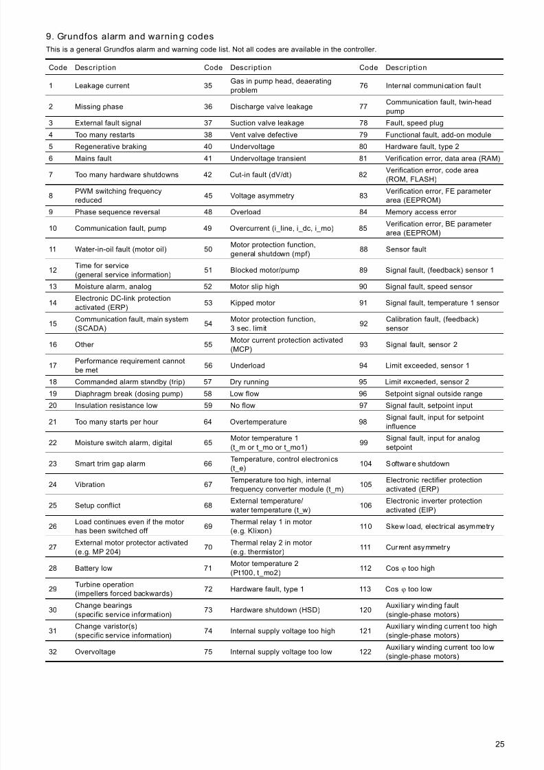
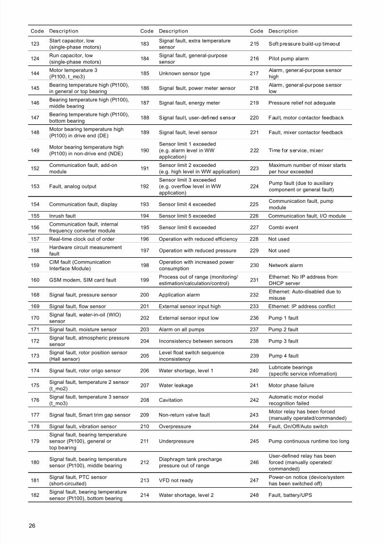
9. Grundfos alarm and warnin g codes
This is a general Grundfos alarm and warning code list. Not all codes are available in the controller.
Code Description Code Description Code Description
1 Leakage current 35Gas in pump head, deaeratingproblem
76 Internal communicat ion faul t
2 Missing phase 36 Discharge valve leakage 77Communication fault, twin-headpump
3 External fault signal 37 Suction valve leakage 78 Fault, speed plug
4 Too many restarts 38 Vent valve defective 79 Functional fault, add-on module5 Regenerative braking 40 Undervoltage 80 Hardware fault, type 2
6 Mains fault 41 Undervoltage transient 81 Verification error, data area (RAM)
7 Too many hardware shutdowns 42 Cut-in fault (dV/dt) 82Verification error, code area(ROM, FLASH)
8PWM switching frequencyreduced
45 Voltage asymmetry 83Verification error, FE parameter area (EEPROM)
9 Phase sequence reversal 48 Overload 84 Memory access error
10 Communication fault, pump 49 Overcurrent (i_line, i_dc, i_mo) 85Verification error, BE parameter area (EEPROM)
11 Water-in-oil fault (motor oil) 50Motor protection function,general shutdown (mpf)
88 Sensor fault
12Time for service(general service information) 51 Blocked motor/pump 89 Signal fault, (feedback) sensor 1
13 Moisture alarm, analog 52 Motor slip high 90 Signal fault, speed sensor
14Electronic DC-link protectionactivated (ERP)
53 Kipped motor 91 Signal fault, temperature 1 sensor
15Communication fault, main system(SCADA)
54Motor protection function,3 sec. limit
92Calibration fault, (feedback)sensor
16 Other 55Motor current protection activated(MCP)
93 Signal fault, sensor 2
17Performance requirement cannotbe met
56 Underload 94 Limit exceeded, sensor 1
18 Commanded alarm standby (trip) 57 Dry running 95 Limit exceeded, sensor 2
19 Diaphragm break (dosing pump) 58 Low flow 96 Setpoint signal outside range
20 Insulation resistance low 59 No flow 97 Signal fault, setpoint input
21 Too many starts per hour 64 Overtemperature 98Signal fault, input for setpointinfluence
22 Moisture switch alarm, digital 65Motor temperature 1(t_m or t_mo or t_mo1)
99Signal fault, input for analogsetpoint
23 Smart trim gap alarm 66Temperature, control electronics(t_e)
104 Software shutdown
24 Vibration 67Temperature too high, internalfrequency converter module (t_m)
105Electronic rectifier protectionactivated (ERP)
25 Setup conflict 68External temperature/water temperature (t_w)
106Electronic inverter protectionactivated (EIP)
26Load continues even if the motor has been switched off
69Thermal relay 1 in motor (e.g. Klixon)
110 Skew load, electrical asymmetry
27 External motor protector activated(e.g. MP 204)
70 Thermal relay 2 in motor (e.g. thermistor)
111 Current asymmetry
28 Battery low 71Motor temperature 2(Pt100, t_mo2)
112 Cos ϕ too high
29Turbine operation(impellers forced backwards)
72 Hardware fault, type 1 113 Cos ϕ too low
30Change bearings(specific service information)
73 Hardware shutdown (HSD) 120 Auxi liary winding fault(single-phase motors)
31Change varistor(s)(specific service information)
74 Internal supply voltage too high 121 Auxi liary winding current too high(single-phase motors)
32 Overvoltage 75 Internal supply voltage too low 122 Auxi liary winding current too low(single-phase motors)
7/23/2019 Functional Profile for Modbus CIU 200-MPC
http://slidepdf.com/reader/full/functional-profile-for-modbus-ciu-200-mpc 26/3826
Code Description Code Description Code Description
123Start capacitor, low(single-phase motors)
183Signal fault, extra temperaturesensor
215 Soft pressure build-up t imeout
124Run capacitor, low(single-phase motors)
184Signal fault, general-purposesensor
216 Pilot pump alarm
144Motor temperature 3(Pt100, t_mo3)
185 Unknown sensor type 217 Alarm, general-purpose sensor high
145Bearing temperature high (Pt100),in general or top bearing
186 Signal fault, power meter sensor 218 Alarm, general-purpose sensor low
146Bearing temperature high (Pt100),middle bearing
187 Signal fault, energy meter 219 Pressure relief not adequate
147Bearing temperature high (Pt100),bottom bearing
188 Signal faul t, user-defined sensor 220 Faul t, motor contactor feedback
148Motor bearing temperature high(Pt100) in drive end (DE)
189 Signal fault, level sensor 221 Fault, mixer contactor feedback
149Motor bearing temperature high(Pt100) in non-drive end (NDE)
190Sensor limit 1 exceeded(e.g. alarm level in WWapplication)
222 Time for service, mixer
152Communication fault, add-onmodule
191Sensor limit 2 exceeded(e.g. high level in WW application)
223Maximum number of mixer startsper hour exceeded
153 Fault, analog output 192Sensor limit 3 exceeded(e.g. overflow level in WW
application)
224Pump fault (due to auxiliary
component or general fault)
154 Communication fault, display 193 Sensor limit 4 exceeded 225Communication fault, pumpmodule
155 Inrush fault 194 Sensor limit 5 exceeded 226 Communication fault, I/O module
156Communication fault, internalfrequency converter module
195 Sensor limit 6 exceeded 227 Combi event
157 Real-time clock out of order 196 Operation with reduced efficiency 228 Not used
158Hardware circuit measurementfault
197 Operation with reduced pressure 229 Not used
159CIM fault (CommunicationInterface Module)
198Operation with increased power consumption
230 Network alarm
160 GSM modem, SIM card fault 199Process out of range (monitoring/
estimation/calculation/control)
231Ethernet: No IP address from
DHCP server 168 Signal fault, pressure sensor 200 Application alarm 232
Ethernet: Auto-disabled due tomisuse
169 Signal fault, flow sensor 201 External sensor input high 233 Ethernet: IP address conflict
170Signal fault, water-in-oil (WIO)sensor
202 External sensor input low 236 Pump 1 fault
171 Signal fault, moisture sensor 203 Alarm on all pumps 237 Pump 2 fault
172Signal fault, atmospheric pressuresensor
204 Inconsistency between sensors 238 Pump 3 fault
173Signal fault, rotor position sensor (Hall sensor)
205Level float switch sequenceinconsistency
239 Pump 4 fault
174 Signal fault, rotor origo sensor 206 Water shortage, level 1 240Lubricate bearings(specific service information)
175 Signal fault, temperature 2 sensor (t_mo2)
207 Water leakage 241 Motor phase failure
176Signal fault, temperature 3 sensor (t_mo3)
208 Cavitation 242 Automat ic motor modelrecognition failed
177 Signal fault, Smart trim gap sensor 209 Non-return valve fault 243Motor relay has been forced(manually operated/commanded)
178 Signal fault, vibration sensor 210 Overpressure 244 Fault, On/Off/Auto switch
179Signal fault, bearing temperaturesensor (Pt100), general or top bearing
211 Underpressure 245 Pump continuous runtime too long
180Signal fault, bearing temperaturesensor (Pt100), middle bearing
212Diaphragm tank prechargepressure out of range
246User-defined relay has beenforced (manually operated/commanded)
181 Signal fault, PTC sensor (short-circuited)
213 VFD not ready 247 Power-on notice (device/systemhas been switched off)
182Signal fault, bearing temperaturesensor (Pt100), bottom bearing
214 Water shortage, level 2 248 Fault, battery/UPS
7/23/2019 Functional Profile for Modbus CIU 200-MPC
http://slidepdf.com/reader/full/functional-profile-for-modbus-ciu-200-mpc 27/3827
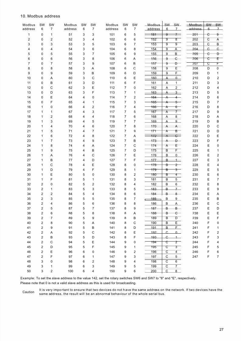
10. Modbus address
Example: To set the slave address to the value 142, set the rotary switches SW6 and SW7 to "8" and "E", respectively.
Please note that 0 is not a valid slave address as this is used for broadcasting.
Modbus
address
SW
6
SW
7
Modbus
address
SW
6
SW
7
Modbus
address
SW
6
SW
7
Modbus
address
SW
6
SW
7
Modbus
address
SW
6
SW
7
1 0 1 51 3 3 101 6 5 151 9 7 201 C 9
2 0 2 52 3 4 102 6 6 152 9 8 202 C A
3 0 3 53 3 5 103 6 7 153 9 9 203 C B
4 0 4 54 3 6 104 6 8 154 9 A 204 C C
5 0 5 55 3 7 105 6 9 155 9 B 205 C D
6 0 6 56 3 8 106 6 A 156 9 C 206 C E7 0 7 57 3 9 107 6 B 157 9 D 207 C F
8 0 8 58 3 A 108 6 C 158 9 E 208 D 0
9 0 9 59 3 B 109 6 D 159 9 F 209 D 1
10 0 A 60 3 C 110 6 E 160 A 0 210 D 2
11 0 B 61 3 D 111 6 F 161 A 1 211 D 3
12 0 C 62 3 E 112 7 0 162 A 2 212 D 4
13 0 D 63 3 F 113 7 1 163 A 3 213 D 5
14 0 E 64 4 0 114 7 2 164 A 4 214 D 6
15 0 F 65 4 1 115 7 3 165 A 5 215 D 7
16 1 0 66 4 2 116 7 4 166 A 6 216 D 8
17 1 1 67 4 3 117 7 5 167 A 7 217 D 9
18 1 2 68 4 4 118 7 6 168 A 8 218 D A
19 1 3 69 4 5 119 7 7 169 A 9 219 D B
20 1 4 70 4 6 120 7 8 170 A A 220 D C
21 1 5 71 4 7 121 7 9 171 A B 221 D D
22 1 6 72 4 8 122 7 A 172 A C 222 D E
23 1 7 73 4 9 123 7 B 173 A D 223 D F
24 1 8 74 4 A 124 7 C 174 A E 224 E 0
25 1 9 75 4 B 125 7 D 175 B F 225 E 1
26 1 A 76 4 C 126 7 E 176 B 0 226 E 2
27 1 B 77 4 D 127 7 F 177 B 1 227 E 3
28 1 C 78 4 E 128 8 0 178 B 2 228 E 4
29 1 D 79 4 F 129 8 1 179 B 3 229 E 5
30 1 E 80 5 0 130 8 2 180 B 4 230 E 6
31 1 F 81 5 1 131 8 3 181 B 5 231 E 732 2 0 82 5 2 132 8 4 182 B 6 232 E 8
33 2 1 83 5 3 133 8 5 183 B 7 233 E 9
34 2 2 84 5 4 134 8 6 184 B 8 234 E A
35 2 3 85 5 5 135 8 7 185 B 9 235 E B
36 2 4 86 5 6 136 8 8 186 B A 236 E C
37 2 5 87 5 7 137 8 9 187 B B 237 E D
38 2 6 88 5 8 138 8 A 188 B C 238 E E
39 2 7 89 5 9 139 8 B 189 B D 239 E F
40 2 8 90 5 A 140 8 C 190 B E 240 F 0
41 2 9 91 5 B 141 8 D 191 B F 241 F 1
42 2 A 92 5 C 142 8 E 192 C 0 242 F 2
43 2 B 93 5 D 143 8 F 193 C 1 243 F 344 2 C 94 5 E 144 9 0 194 C 2 244 F 4
45 2 D 95 5 F 145 9 1 195 C 3 245 F 5
46 2 E 96 6 0 146 9 2 196 C 4 246 F 6
47 2 F 97 6 1 147 9 3 197 C 5 247 F 7
48 3 0 98 6 2 148 9 4 198 C 6
49 3 1 99 6 3 149 9 5 199 C 7
50 3 2 100 6 4 150 9 6 200 C 8
CautionIt is very impo rtant to ensure that two devices do not h ave the same address on the network. If two devices have the
same address, the result will be an abnormal behaviour of the whole serial bus.

7/23/2019 Functional Profile for Modbus CIU 200-MPC
http://slidepdf.com/reader/full/functional-profile-for-modbus-ciu-200-mpc 28/3828
11. Modbus telegrams and function codes
11.1 Modbus telegram overview
The maximum size of a Modbus RTU telegram is 256 bytes.Telegrams must be separated by a silent interval of at least3.5 character times.
The standard Modbus RTU telegram format is shown in the tablebelow.
A telegram starts with the slave address occupying one byte.Then comes a variable-size data field. For each telegram, a CRCis calculated and appended to the telegram (two bytes total).
All bytes in the telegram, except for the CRC itsel f, are includedin the check.
11.2 Function code overview
The table below shows a list of the supported function codes.
The same data are available in both holding registers and inputregisters, meaning that either function (0x03 or 0x04) can beused for reading data.
Slave address Function code Data CRC
1 byte 1 byte 0 to 252 bytes 2 bytes
NoteThe CRC bytes are not shown i n the examples in
the following sections.
Type Code Hex Name
16-bit data(registers)
03 0x03 Read holding registers04 0x04 Read input registers
06 0x06 Write s ingle register
16 0x10 Write multiple registers
Diagnostics 08 08DiagnosticsSee section 11.7 Diagnostics
(0x08) for subcodes.
Note Reading or writin g coils are not supported.
7/23/2019 Functional Profile for Modbus CIU 200-MPC
http://slidepdf.com/reader/full/functional-profile-for-modbus-ciu-200-mpc 29/3829
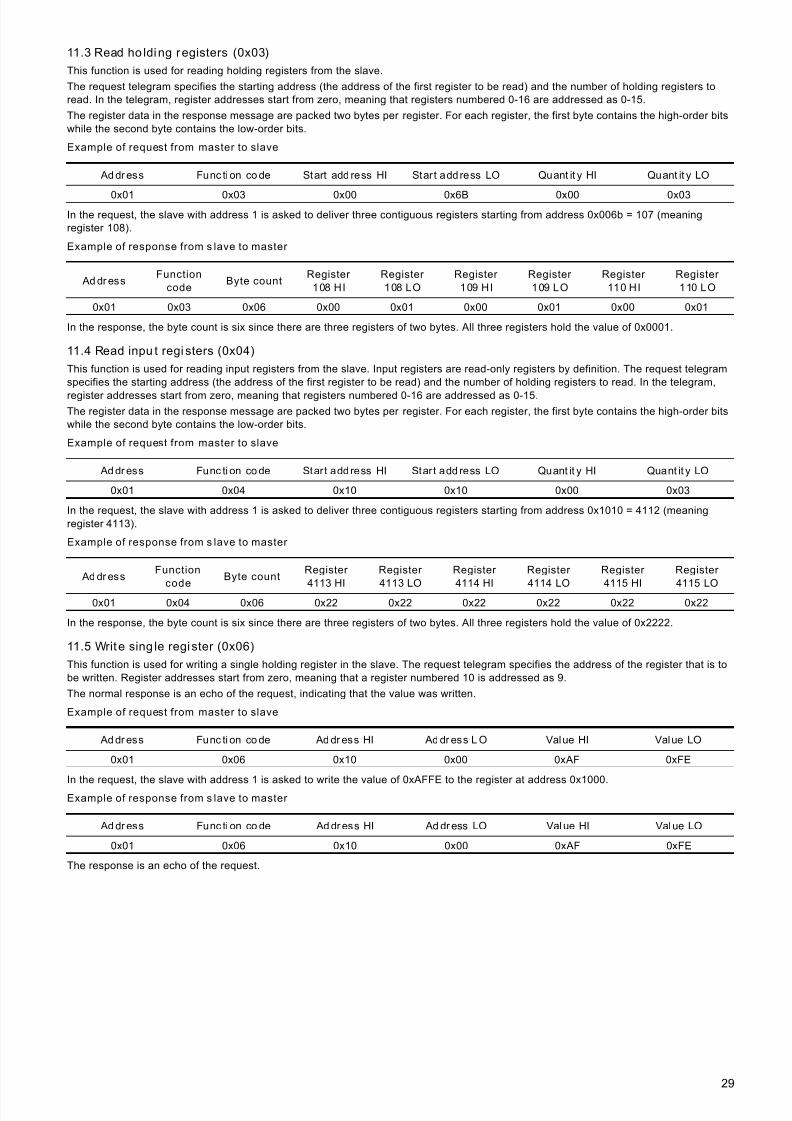
11.3 Read ho lding registers (0x03)
This function is used for reading holding registers from the slave.
The request telegram specifies the starting address (the address of the first register to be read) and the number of holding registers toread. In the telegram, register addresses start from zero, meaning that registers numbered 0-16 are addressed as 0-15.
The register data in the response message are packed two bytes per register. For each register, the first byte contains the high-order bitswhile the second byte contains the low-order bits.
Example of request from master to slave
In the request, the slave with address 1 is asked to deliver three contiguous registers starting from address 0x006b = 107 (meaningregister 108).
Example of response from s lave to master
In the response, the byte count is six since there are three registers of two bytes. All three registers hold the value of 0x0001.
11.4 Read inpu t regi sters (0x04)
This function is used for reading input registers from the slave. Input registers are read-only registers by definition. The request telegramspecifies the starting address (the address of the first register to be read) and the number of holding registers to read. In the telegram,
register addresses start from zero, meaning that registers numbered 0-16 are addressed as 0-15.The register data in the response message are packed two bytes per register. For each register, the first byte contains the high-order bitswhile the second byte contains the low-order bits.
Example of request from master to slave
In the request, the slave with address 1 is asked to deliver three contiguous registers starting from address 0x1010 = 4112 (meaningregister 4113).
Example of response from s lave to master
In the response, the byte count is six since there are three registers of two bytes. All three registers hold the value of 0x2222.
11.5 Write sing le register (0x06)
This function is used for writing a single holding register in the slave. The request telegram specifies the address of the register that is tobe written. Register addresses start from zero, meaning that a register numbered 10 is addressed as 9.
The normal response is an echo of the request, indicating that the value was written.
Example of request from master to slave
In the request, the slave with address 1 is asked to write the value of 0xAFFE to the register at address 0x1000.
Example of response from s lave to master
The response is an echo of the request.
Ad dr ess Func ti on co de Start add ress HI Start add ress LO Quant it y HI Quant it y LO
0x01 0x03 0x00 0x6B 0x00 0x03
Ad dr essFunction
codeByte count
Register
108 HI
Register
108 LO
Register
109 HI
Register
109 LO
Register
110 HI
Register
110 LO
0x01 0x03 0x06 0x00 0x01 0x00 0x01 0x00 0x01
Ad dr ess Func ti on co de Start add ress HI Start add ress LO Quant it y HI Quant it y LO
0x01 0x04 0x10 0x10 0x00 0x03
Ad dr essFunction
codeByte count
Register
4113 HI
Register
4113 LO
Register
4114 HI
Register
4114 LO
Register
4115 HI
Register
4115 LO
0x01 0x04 0x06 0x22 0x22 0x22 0x22 0x22 0x22
Ad dr ess Func ti on co de Ad dr ess HI Ad dr ess L O Value HI Value LO
0x01 0x06 0x10 0x00 0xAF 0xFE
Ad dr ess Func ti on co de Ad dr ess HI Ad dr ess LO Value HI Value LO
0x01 0x06 0x10 0x00 0xAF 0xFE

7/23/2019 Functional Profile for Modbus CIU 200-MPC
http://slidepdf.com/reader/full/functional-profile-for-modbus-ciu-200-mpc 30/3830
11.6 Write mul tip le regist ers (0x10)
This function is used for writing a block of contiguous holding registers in the slave. Register addresses start from zero, meaning that aregister numbered 100 is addressed as 99.
Example of request from master to slave
In the request, the slave with address 1 is asked to write the value of 0x0001 to the register at address 0x0020 and the value of 0xB0B0
to the register at address 0x0021.Example of response from s lave to master
The response returns the function code, starting address and quantity of registers written.
Ad dr essFunction
code
Start
address HI
Start
address LO
Quantity
HI
Quantity
LO
Byte
count
Register
33 HI
Register
33 LO
Register
34 HI
Register
34 LO
0x01 0x10 0x00 0x20 0x00 0x02 0x04 0x00 0x01 0xB0 0xB0
Ad dr ess Func ti on co de Start add res s HI Start add ress LO Quant it y wr it ten HI Quant it y w ri tt en LO
0x01 0x10 0x00 0x20 0x00 0x02
7/23/2019 Functional Profile for Modbus CIU 200-MPC
http://slidepdf.com/reader/full/functional-profile-for-modbus-ciu-200-mpc 31/3831
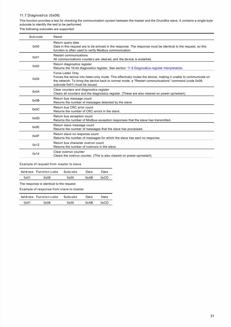
11.7 Diagnosti cs (0x08)
This function provides a test for checking the communication system between the master and the Grundfos slave. It contains a single-bytesubcode to identify the test to be performed.
The following subcodes are supported:
Example of request from master to slave
The response is identical to the request.
Example of response from s lave to master
Subcode Name
0x00Return query dataData in this request are to be echoed in the response. The response must be identical to the request, so thisfunction is often used to verify Modbus communication.
0x01Restart communications
All communications counters are cleared, and the device is restarted.
0x02Return diagnostics register Returns the 16-bit diagnostics register. See section 11.8 Diagnostics register interpretation.
0x04
Force Listen OnlyForces the device into listen-only mode. This effectively mutes the device, making it unable to communicate onthe network. To bring the device back to normal mode, a "Restart communications" command (code 0x08,subcode 0x01) must be issued.
0x0AClear counters and diagnostics register Clears all counters and the diagnostics register. (These are also cleared on power-up/restart).
0x0BReturn bus message countReturns the number of messages detected by the slave.
0x0CReturn bus CRC error countReturns the number of CRC errors in the slave.
0x0DReturn bus exception countReturns the number of Modbus exception responses that the slave has transmitted.
0x0EReturn slave message countReturns the number of messages that the slave has processed.
0x0FReturn slave no response countReturns the number of messages for which the slave has sent no response.
0x12Return bus character overrun countReturns the number of overruns in the slave.
0x14Clear overrun counter Clears the overrun counter. (This is also cleared on power-up/restart).
Ad dr ess Fun ct io n c od e Subc od e Data Data
0x01 0x08 0x00 0xAB 0xCD
Ad dr ess Fun ct io n c od e Subc od e Data Data
0x01 0x08 0x00 0xAB 0xCD
7/23/2019 Functional Profile for Modbus CIU 200-MPC
http://slidepdf.com/reader/full/functional-profile-for-modbus-ciu-200-mpc 32/3832
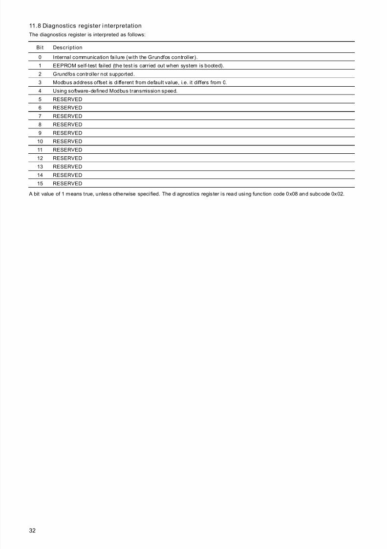
11.8 Diagnostics register i nterpretation
The diagnostics register is interpreted as follows:
A bit value of 1 means t rue, unless otherwise speci fied. The diagnost ics register is read using function code 0x08 and subcode 0x02.
Bit Description
0 Internal communication failure (with the Grundfos controller).
1 EEPROM self-test failed (the test is carried out when system is booted).
2 Grundfos controller not supported.
3 Modbus address offset is different from default value, i.e. it differs from 0.
4 Using software-defined Modbus transmission speed.
5 RESERVED
6 RESERVED
7 RESERVED
8 RESERVED
9 RESERVED
10 RESERVED
11 RESERVED
12 RESERVED
13 RESERVED
14 RESERVED
15 RESERVED
7/23/2019 Functional Profile for Modbus CIU 200-MPC
http://slidepdf.com/reader/full/functional-profile-for-modbus-ciu-200-mpc 33/3833
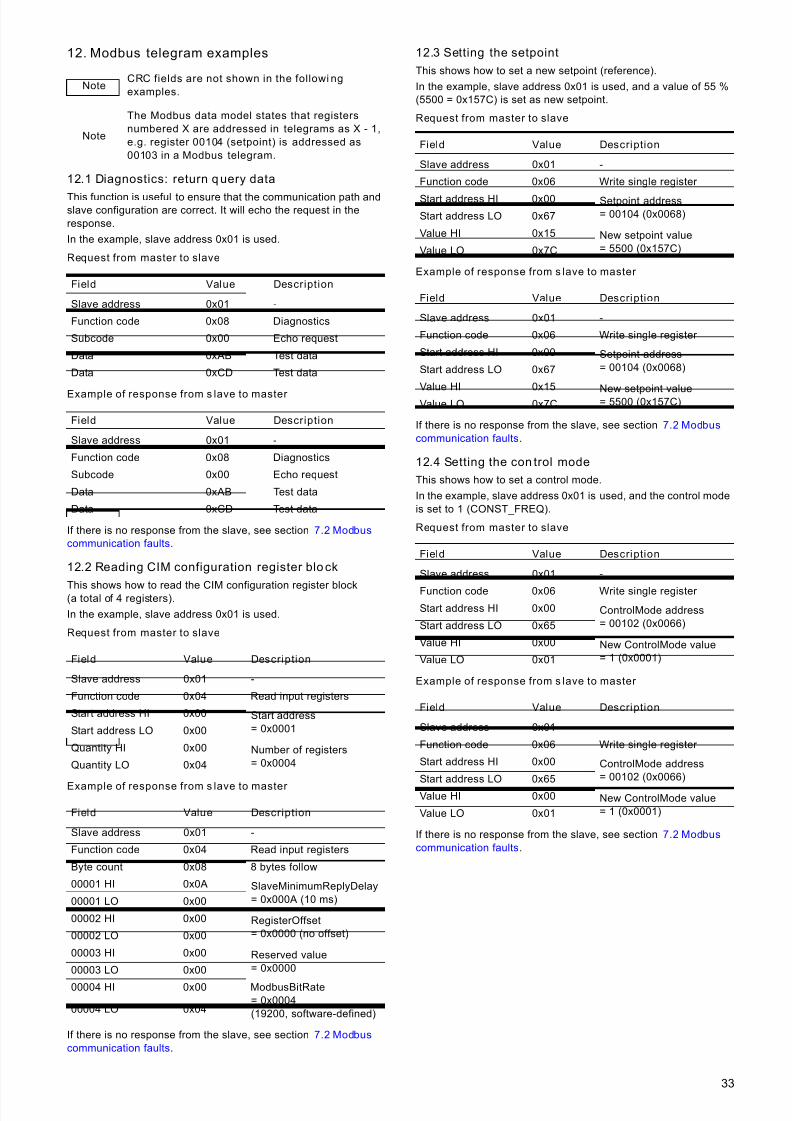
12. Modbus telegram examples
12.1 Diagnostics: return query data
This function is useful to ensure that the communication path andslave configuration are correct. It will echo the request in theresponse.
In the example, slave address 0x01 is used.
Request from master to slave
Example of response from s lave to master
If there is no response from the slave, see section 7.2 Modbus
communication faults.
12.2 Reading CIM configuration register block
This shows how to read the CIM configuration register block(a total of 4 registers).
In the example, slave address 0x01 is used.
Request from master to slave
Example of response from s lave to master
If there is no response from the slave, see section 7.2 Modbus
communication faults.
12.3 Setting the setpoint
This shows how to set a new setpoint (reference).
In the example, slave address 0x01 is used, and a value of 55 %(5500 = 0x157C) is set as new setpoint.
Request from master to slave
Example of response from s lave to master
If there is no response from the slave, see section 7.2 Modbus
communication faults.
12.4 Setting the con trol mode
This shows how to set a control mode.
In the example, slave address 0x01 is used, and the control modeis set to 1 (CONST_FREQ).
Request from master to slave
Example of response from s lave to master
If there is no response from the slave, see section 7.2 Modbus
communication faults.
NoteCRC fields are not shown in the followi ng
examples.
Note
The Modbus data model states that registers
numbered X are addressed in telegrams as X - 1,
e.g. register 00104 (setpoint) is addressed as
00103 in a Modbus telegram.
Field Value Description
Slave address 0x01 -
Function code 0x08 Diagnostics
Subcode 0x00 Echo request
Data 0xAB Test data
Data 0xCD Test data
Field Value Description
Slave address 0x01 -
Function code 0x08 Diagnostics
Subcode 0x00 Echo request
Data 0xAB Test data
Data 0xCD Test data
Field Value Description
Slave address 0x01 -
Function code 0x04 Read input registers
Start address HI 0x00 Start address= 0x0001Start address LO 0x00
Quantity HI 0x00 Number of registers= 0x0004Quantity LO 0x04
Field Value Description
Slave address 0x01 -
Function code 0x04 Read input registers
Byte count 0x08 8 bytes follow
00001 HI 0x0A SlaveMinimumReplyDelay= 0x000A (10 ms)00001 LO 0x00
00002 HI 0x00 RegisterOffset= 0x0000 (no offset)00002 LO 0x00
00003 HI 0x00 Reserved value= 0x000000003 LO 0x00
00004 HI 0x00 ModbusBitRate= 0x0004(19200, software-defined)00004 LO 0x04
Field Value Description
Slave address 0x01 -
Function code 0x06 Write single register
Start address HI 0x00 Setpoint address= 00104 (0x0068)Start address LO 0x67
Value HI 0x15 New setpoint value= 5500 (0x157C)Value LO 0x7C
Field Value Description
Slave address 0x01 -
Function code 0x06 Write single register
Start address HI 0x00 Setpoint address= 00104 (0x0068)Start address LO 0x67
Value HI 0x15New setpoint value= 5500 (0x157C)Value LO 0x7C
Field Value Description
Slave address 0x01 -
Function code 0x06 Write single register Start address HI 0x00 ControlMode address
= 00102 (0x0066)Start address LO 0x65
Value HI 0x00 New ControlMode value= 1 (0x0001)Value LO 0x01
Field Value Description
Slave address 0x01 -
Function code 0x06 Write single register
Start address HI 0x00 ControlMode address= 00102 (0x0066)Start address LO 0x65
Value HI 0x00 New ControlMode value= 1 (0x0001)Value LO 0x01
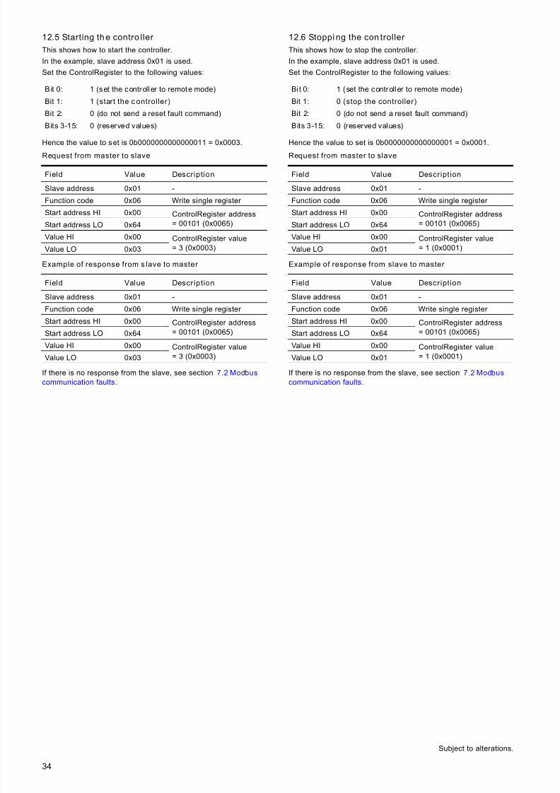
7/23/2019 Functional Profile for Modbus CIU 200-MPC
http://slidepdf.com/reader/full/functional-profile-for-modbus-ciu-200-mpc 34/3834
12.5 Starting the contro ller
This shows how to start the controller.
In the example, slave address 0x01 is used.
Set the ControlRegister to the following values:
Hence the value to set is 0b0000000000000011 = 0x0003.
Request from master to slave
Example of response from s lave to master
If there is no response from the slave, see section 7.2 Modbus
communication faults.
12.6 Stoppi ng the con troller
This shows how to stop the controller.
In the example, slave address 0x01 is used.
Set the ControlRegister to the following values:
Hence the value to set is 0b0000000000000001 = 0x0001.
Request from master to slave
Example of response from slave to master
If there is no response from the slave, see section 7.2 Modbus
communication faults.
B it 0: 1 (set the controller to remote mode)
Bit 1: 1 (start the c ontroller)
Bit 2: 0 (do not send a reset fault command)
Bits 3-15: 0 (reserved values)
Field Value Description
Slave address 0x01 -
Function code 0x06 Write single register
Start address HI 0x00 ControlRegister address= 00101 (0x0065)Start address LO 0x64
Value HI 0x00 ControlRegister value= 3 (0x0003)Value LO 0x03
Field Value Description
Slave address 0x01 -
Function code 0x06 Write single register
Start address HI 0x00 ControlRegister address= 00101 (0x0065)Start address LO 0x64
Value HI 0x00 ControlRegister value= 3 (0x0003)Value LO 0x03
Bi t 0: 1 (set the controller to remote mode)
Bit 1: 0 (stop the controller)
Bit 2: 0 (do not send a reset fault command)
Bits 3-15: 0 (reserved values)
Field Value Description
Slave address 0x01 -
Function code 0x06 Write single register
Start address HI 0x00 ControlRegister address= 00101 (0x0065)Start address LO 0x64
Value HI 0x00 ControlRegister value= 1 (0x0001)Value LO 0x01
Field Value Description
Slave address 0x01 -
Function code 0x06 Write single register
Start address HI 0x00 ControlRegister address= 00101 (0x0065)Start address LO 0x64
Value HI 0x00 ControlRegister value= 1 (0x0001)Value LO 0x01
Subject to alterations.

7/23/2019 Functional Profile for Modbus CIU 200-MPC
http://slidepdf.com/reader/full/functional-profile-for-modbus-ciu-200-mpc 35/3835

7/23/2019 Functional Profile for Modbus CIU 200-MPC
http://slidepdf.com/reader/full/functional-profile-for-modbus-ciu-200-mpc 36/38
Ar gen ti naBombas GRUNDFOS de Argentina S.A.Ruta Panamericana km. 37.500 Lote34A1619 - GarinPcia. de Buenos AiresPhone: +54-3327 414 444Telefax: +54-3327 411 111
Au st ral iaGRUNDFOS Pumps Pty. Ltd.P.O. Box 2040Regency ParkSouth Australia 5942Phone: +61-8-8461-4611
Telefax: +61-8-8340 0155
Au st ri aGRUNDFOS Pumpen VertriebGes.m.b.H.Grundfosstraße 2 A-5082 Grödig/SalzburgTel.: +43-6246-883-0Telefax: +43-6246-883-30
BelgiumN.V. GRUNDFOS Bellux S.A.Boomsesteenweg 81-83B-2630 Aartselaar Tél.: +32-3-870 7300Télécopie: +32-3-870 7301
BelorussiaПредставительство ГРУНДФОС в Минске220123, Минск ,ул. В. Хоружей, 22, оф. 1105Тел.: +(37517) 233 97 65,Факс: +(37517) 233 97 69E-mail: [email protected]
Bosnia/HerzegovinaGRUNDFOS SarajevoTrg Heroja 16,BiH-71000 SarajevoPhone: +387 33 713 290Telefax: +387 33 659 079e-mail: [email protected]
BrazilBOMBAS GRUNDFOS DO BRASIL Av. Humberto de A lencar CasteloBranco, 630CEP 09850 - 300São Bernardo do Campo - SPPhone: +55-11 4393 5533
Telefax: +55-11 4343 5015BulgariaGRUNDFOS Pumpen VertriebRepresentative Office - BulgariaBulgaria, 1421 SofiaLozenetz District105-107 Arsenalski blvd.Phone: +359 2963 3820, 2963 5653Telefax: +359 2963 1305
CanadaGRUNDFOS Canada Inc.2941 Brighton RoadOakville, OntarioL6H 6C9Phone: +1-905 829 9533Telefax: +1-905 829 9512
ChinaGRUNDFOS Pumps (Shanghai) Co. Ltd.
51 Floor, Raffles CityNo. 268 Xi Zang Road. (M)Shanghai 200001PRCPhone: +86-021-612 252 22Telefax: +86-021-612 253 33
CroatiaGRUNDFOS CROATIA d.o.o.Cebini 37, BuzinHR-10010 ZagrebPhone: +385 1 6595 400Telefax: +385 1 6595 499www.grundfos.hr
Czech RepublicGRUNDFOS s.r.o.Čajkovského 21779 00 OlomoucPhone: +420-585-716 111
Telefax: +420-585-716 299
DenmarkGRUNDFOS DK A/SMartin Bachs Vej 3DK-8850 BjerringbroTlf.: +45-87 50 50 50Telefax: +45-87 50 51 51E-mail: [email protected]/DK
EstoniaGRUNDFOS Pumps Eesti OÜPeterburi tee 92G11415 TallinnTel: + 372 606 1690Fax: + 372 606 1691
FinlandOY GRUNDFOS Pumput ABMestarintie 11FIN-01730 VantaaPhone: +358-3066 5650Telefax: +358-3066 56550
FrancePompes GRUNDFOS Distribution S.A.Parc d’Activités de Chesnes57, rue de MalacombeF-38290 St. Quentin Fallavier (Lyon)Tél.: +33-4 74 82 15 15Télécopie: +33-4 74 94 10 51
GermanyGRUNDFOS GMBHSchlüterstr. 3340699 ErkrathTel.: +49-(0) 211 929 69-0Telefax: +49-(0) 211 929 69-3799e-mail: [email protected] in Deutschland:e-mail: [email protected]
GreeceGRUNDFOS Hellas A.E.B.E.20th km. Athinon-Markopoulou Av.P.O. Box 71GR-19002 PeaniaPhone: +0030-210-66 83 400Telefax: +0030-210-66 46 273
Hong KongGRUNDFOS Pumps (Hong Kong) Ltd.Unit 1, Ground floor Siu Wai Industrial Centre29-33 Wing Hong Street &68 King Lam Street, Cheung Sha WanKowloon
Phone: +852-27861706 / 27861741Telefax: +852-27858664
HungaryGRUNDFOS Hungária Kft.Park u. 8H-2045 Törökbálint,Phone: +36-23 511 110Telefax: +36-23 511 111
IndiaGRUNDFOS Pumps India Private Lim-ited118 Old Mahabalipuram RoadThoraipakkamChennai 600 096Phone: +91-44 2496 6800
IndonesiaPT GRUNDFOS PompaJl. Rawa Sumur III, Blok III / CC-1
Kawasan Industri, PulogadungJakarta 13930Phone: +62-21-460 6909Telefax: +62-21-460 6910 / 460 6901
IrelandGRUNDFOS (Ireland) Ltd.Unit A, Merrywell Business ParkBallymount Road Lower Dublin 12Phone: +353-1-4089 800Telefax: +353-1-4089 830
ItalyGRUNDFOS Pompe Italia S.r.l.Via Gran Sasso 4I-20060 Truccazzano (Milano)Tel.: +39-02-95838112Telefax: +39-02-95309290 / 95838461
Japan
GRUNDFOS Pumps K.K.Gotanda Metalion Bldg., 5F,5-21-15, Higashi-gotandaShiagawa-ku, Tokyo141-0022 JapanPhone: +81 35 448 1391Telefax: +81 35 448 9619
KoreaGRUNDFOS Pumps Korea Ltd.6th Floor, Aju Building 679-5Yeoksam-dong, Kangnam-ku, 135-916Seoul, KoreaPhone: +82-2-5317 600Telefax: +82-2-5633 725
LatviaSIA GRUNDFOS Pumps LatviaDeglava biznesa centrs Augusta Deglava ielā 60, LV-1035, R ī ga,Tālr.: + 371 714 9640, 7 149 641Fakss: + 371 914 9646
LithuaniaGRUNDFOS Pumps UABSmolensko g. 6LT-03201 Vilniu sTel: + 370 52 395 430Fax: + 370 52 395 431
MalaysiaGRUNDFOS Pumps Sdn. Bhd.7 Jalan Peguam U1/25Glenmarie Industrial Park40150 Shah AlamSelangor Phone: +60-3-5569 2922Telefax: +60-3-5569 2866
MéxicoBombas GRUNDFOS de México S.A. deC.V.Boulevard TLC No. 15Parque Industrial Stiva Aeropuerto Apodaca, N.L . 66600Phone: +52-81-8144 4000Telefax: +52-81-8144 4010
NetherlandsGRUNDFOS NetherlandsVeluwezoom 351326 AE AlmerePostbus 220151302 CA ALMERETel.: +31-88-478 6336Telefax: +31-88-478 6332e-mail: [email protected]
New ZealandGRUNDFOS Pumps NZ Ltd.17 Beatrice Tinsley CrescentNorth Harbour Industrial Estate Albany, AucklandPhone: +64-9-415 3240
Telefax: +64-9-415 3250NorwayGRUNDFOS Pumper A/SStrømsveien 344Postboks 235, LeirdalN-1011 OsloTlf.: +47-22 90 47 00Telefax: +47-22 32 21 50
PolandGRUNDFOS Pompy Sp. z o.o.ul. Klonowa 23Baranowo k. PoznaniaPL-62-081 PrzeźmierowoTel: (+48-61) 650 13 00Fax: (+48-61) 650 13 50
PortugalBombas GRUNDFOS Portugal, S.A.Rua Calvet de Magalhães, 241
Apartado 1079P-2770-153 Paço de ArcosTel.: +351-21-440 76 00Telefax: +351-21-440 76 90
RomâniaGRUNDFOS Pompe România SRLBd. Biruintei, nr 103Pantelimon county IlfovPhone: +40 21 200 4100Telefax: +40 21 200 4101E-mail: [email protected]
RussiaООО ГрундфосРоссия, 109544 Москва, ул. Школьная 39Тел. (+7) 495 737 30 00, 564 88 00Факс (+7) 495 737 75 36, 564 88 11E-mail
[email protected] Predstavništvo BeogradDr. Milutina Ivkovića 2a/29YU-11000 BeogradPhone: +381 11 26 47 877 / 11 26 47496Telefax: +381 11 26 48 340
SingaporeGRUNDFOS (Singapore) Pte. Ltd.24 Tuas West RoadJurong TownSingapore 638381Phone: +65-6865 1222Telefax: +65-6861 8402
SloveniaGRUNDFOS d.o.o.Šlandrova 8b, SI-1231 Ljubljana-ČrnučePhone: +386 1 568 0610Telefax: +386 1 568 0619E-mail: [email protected]
South AfricaCorner Mountjoy and George AllenRoadsWilbart Ext. 2Bedfordview 2008Phone: (+27) 11 579 4800Fax: (+27) 11 455 6066E-mail: [email protected]
SpainBombas GRUNDFOS España S.A.Camino de la Fuentecilla, s/nE-28110 Algete (Madrid)Tel.: +34-91-848 8800Telefax: +34-91-628 0465
SwedenGRUNDFOS ABBox 333 (Lunnagårdsgatan 6)431 24 MölndalTel.: +46(0)771-32 23 00Telefax: +46(0)31-331 94 60
SwitzerlandGRUNDFOS Pumpen AGBruggacherstrasse 10CH-8117 Fällanden/ZHTel.: +41-1-806 8111Telefax: +41-1-806 8115
TaiwanGRUNDFOS Pumps (Taiwan) Ltd.7 Floor, 219 Min-Chuan RoadTaichung, Taiwan, R.O.C.Phone: +886-4-2305 0868Telefax: +886-4-2305 0878
ThailandGRUNDFOS (Thailand) Ltd.92 Chaloem Phrakiat Rama 9 Road,Dokmai, Pravej, Bangkok 10250
Phone: +66-2-725 8999Telefax: +66-2-725 8998
TurkeyGRUNDFOS POMPA San. ve Tic. Ltd.Sti.Gebze Organize Sanayi BölgesiIhsan dede Caddesi,2. yol 200. Sokak No. 20441490 Gebze/ KocaeliPhone: +90 - 262-679 7979Telefax: +90 - 262-679 7905E-mail: [email protected]
UkraineТОВ ГРУНДФОС УКРАЇНА 01010 Київ, Вул. Московська 8б,Тел.:(+38 044) 390 40 50Фах.: (+38 044) 390 40 59E-mail: [email protected]
United Arab EmiratesGRUNDFOS Gulf DistributionP.O. Box 16768Jebel Ali Free ZoneDubaiPhone: +971-4- 8815 166Telefax: +971-4-8815 136
United KingdomGRUNDFOS Pumps Ltd.Grovebury RoadLeighton Buzzard/Beds. LU7 8TLPhone: +44-1525-850000Telefax: +44-1525-850011
U.S.A.GRUNDFOS Pumps Corporation17100 West 118th TerraceOlathe, Kansas 66061Phone: +1-913-227-3400Telefax: +1-913-227-3500
UsbekistanПредставительство ГРУНДФОС в Ташкенте700000 Ташкент ул.Усмана Носира 1-й тупик 5Телефон: (3712) 55-68-15Факс: (3712) 53-36-35
Addresses revised 20.05.2010

7/23/2019 Functional Profile for Modbus CIU 200-MPC
http://slidepdf.com/reader/full/functional-profile-for-modbus-ciu-200-mpc 37/38

7/23/2019 Functional Profile for Modbus CIU 200-MPC
http://slidepdf.com/reader/full/functional-profile-for-modbus-ciu-200-mpc 38/38
Being responsible is our foundationThinking ahead makes it possible
Innovation is the essence
The name Grundfos, the Grundfos logo, and the payoff Be–Think–Innovate are registrated trademarksowned by Grundfos Management A/S or Grundfos A/S, Denmark. All rights reserved worldwide.
96846342 0810GB
Repl. 96846342 0809