Embed Size (px)
Citation preview
Fully integrated signal and power isolation – applications and benefits
Vikas Kumar ThawaniSystems engineerIsolation, Interface GroupTexas Instruments
Anand ReghunathanApplications engineerIsolation, Interface GroupTexas Instruments
I 2 Fully integrated signal and power isolation – applications and benefits March 2017
To be truly useful, an integrated power and signal isolation solution must offer high efficiency, high power delivery and low emissions while offering high isolation performance.
Isolation is a means of preventing direct current (DC) and unwanted alternating
current (AC) between two parts of a system while still enabling signal and power
transfer between those two parts. Isolation is used in a wide variety of applications:
to protect human operators and low-voltage circuitry from high voltages, to improve
noise immunity, and to handle ground potential differences between communicating
subsystems.
Isolators with complementary metal-oxide-
semiconductor (CMOS)- or transistor-transistor
logic (TTL)-level inputs and outputs are called
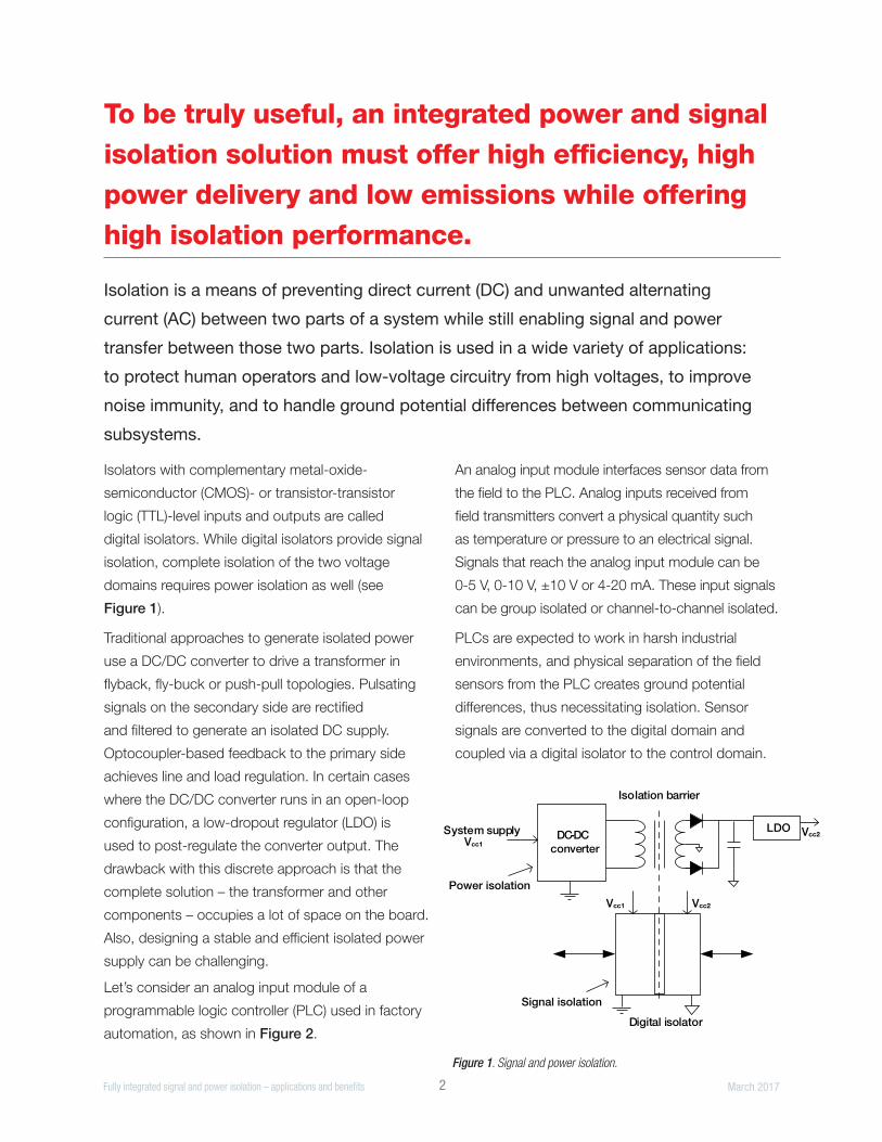
digital isolators. While digital isolators provide signal
isolation, complete isolation of the two voltage
domains requires power isolation as well (see
Figure 1).
Traditional approaches to generate isolated power
use a DC/DC converter to drive a transformer in
flyback, fly-buck or push-pull topologies. Pulsating
signals on the secondary side are rectified
and filtered to generate an isolated DC supply.
Optocoupler-based feedback to the primary side
achieves line and load regulation. In certain cases
where the DC/DC converter runs in an open-loop
configuration, a low-dropout regulator (LDO) is
used to post-regulate the converter output. The
drawback with this discrete approach is that the
complete solution – the transformer and other
components – occupies a lot of space on the board.
Also, designing a stable and efficient isolated power
supply can be challenging.
Let’s consider an analog input module of a
programmable logic controller (PLC) used in factory
automation, as shown in Figure 2.
An analog input module interfaces sensor data from
the field to the PLC. Analog inputs received from
field transmitters convert a physical quantity such
as temperature or pressure to an electrical signal.
Signals that reach the analog input module can be
0-5 V, 0-10 V, ±10 V or 4-20 mA. These input signals
can be group isolated or channel-to-channel isolated.
PLCs are expected to work in harsh industrial
environments, and physical separation of the field
sensors from the PLC creates ground potential
differences, thus necessitating isolation. Sensor
signals are converted to the digital domain and
coupled via a digital isolator to the control domain.
Figure 1. Signal and power isolation.
DC-DCconverter
LDO
Isolation barrier
Digital isolator
System supplyVcc1
Vcc2
Vcc1 Vcc2
Signal isolation
Power isolation
I 3 Fully integrated signal and power isolation – applications and benefits March 2017
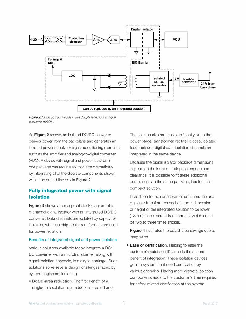
As Figure 2 shows, an isolated DC/DC converter
derives power from the backplane and generates an
isolated power supply for signal-conditioning elements
such as the amplifier and analog-to-digital converter
(ADC). A device with signal and power isolation in
one package can reduce solution size dramatically
by integrating all of the discrete components shown
within the dotted-line box in Figure 2.
Fully integrated power with signal isolation
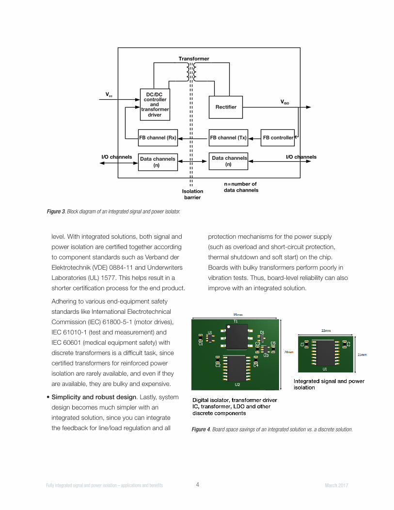
Figure 3 shows a conceptual block diagram of a
n-channel digital isolator with an integrated DC/DC
converter. Data channels are isolated by capacitive
isolation, whereas chip-scale transformers are used
for power isolation.
Benefits of integrated signal and power isolation
Various solutions available today integrate a DC/
DC converter with a microtransformer, along with
signal-isolation channels, in a single package. Such
solutions solve several design challenges faced by
system engineers, including:
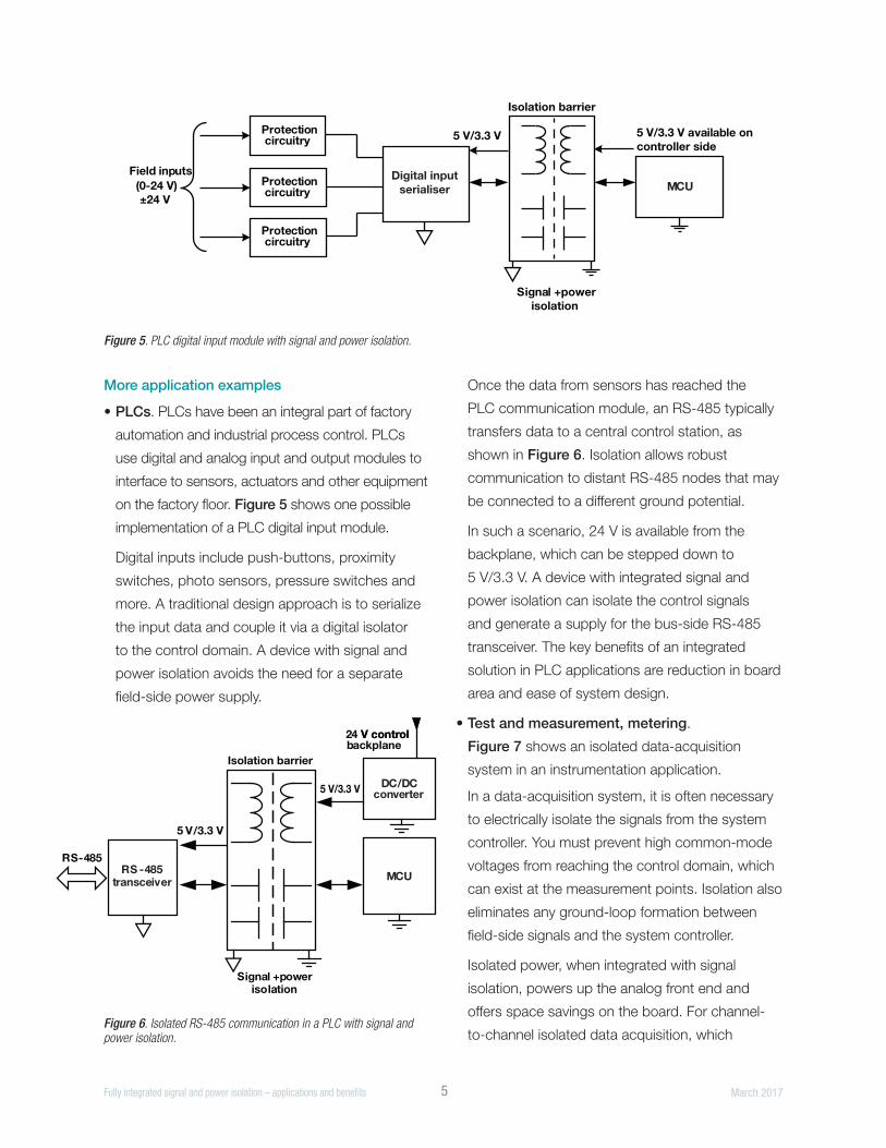
• Board-area reduction. The first benefit of a
single-chip solution is a reduction in board area.
The solution size reduces significantly since the
power stage, transformer, rectifier diodes, isolated
feedback and digital data-isolation channels are
integrated in the same device.
Because the digital isolator package dimensions
depend on the isolation ratings, creepage and
clearance, it is possible to fit these additional
components in the same package, leading to a
compact solution.
In addition to the surface-area reduction, the use
of planar transformers enables the z-dimension
or height of the integrated solution to be lower
(~3mm) than discrete transformers, which could
be two to three times thicker.
Figure 4 illustrates the board-area savings due to
integration.
• Ease of certification. Helping to ease the
customer’s safety certification is the second
benefit of integration. These isolation devices
go into systems that need certification by
various agencies. Having more discrete isolation
components adds to the customer’s time required
for safety-related certification at the system
Figure 2. An analog input module in a PLC application requires signal and power isolation.
Digital isolator
ISO Barrier
Protection circuitry
Amp MCU
24 V frombackplane
4-20 mA
5VIsolated DC/DC
converter
DC/DCconverter
LDO
To amp & ADC
Can be replaced by an integrated solution
ADC
I 4 Fully integrated signal and power isolation – applications and benefits March 2017
level. With integrated solutions, both signal and
power isolation are certified together according
to component standards such as Verband der
Elektrotechnik (VDE) 0884-11 and Underwriters
Laboratories (UL) 1577. This helps result in a
shorter certification process for the end product.
Adhering to various end-equipment safety
standards like International Electrotechnical
Commission (IEC) 61800-5-1 (motor drives),
IEC 61010-1 (test and measurement) and
IEC 60601 (medical equipment safety) with
discrete transformers is a difficult task, since
certified transformers for reinforced power
isolation are rarely available, and even if they
are available, they are bulky and expensive.
• Simplicity and robust design. Lastly, system
design becomes much simpler with an
integrated solution, since you can integrate
the feedback for line/load regulation and all
protection mechanisms for the power supply
(such as overload and short-circuit protection,
thermal shutdown and soft start) on the chip.
Boards with bulky transformers perform poorly in
vibration tests. Thus, board-level reliability can also
improve with an integrated solution.
Figure 4. Board space savings of an integrated solution vs. a discrete solution.
Figure 3. Block diagram of an integrated signal and power isolator.
FB channel (Rx)
DC/DC controller
and transformer
driver
Data channels (n)
FB channel (Tx)
Data channels (n)
FB controller
Rectifier
Transformer
Vcc
I/O channels I/O channels
VISO
n=number of data channelsIsolation
barrier
I 5 Fully integrated signal and power isolation – applications and benefits March 2017
More application examples
• PLCs. PLCs have been an integral part of factory
automation and industrial process control. PLCs
use digital and analog input and output modules to
interface to sensors, actuators and other equipment
on the factory floor. Figure 5 shows one possible
implementation of a PLC digital input module.
Digital inputs include push-buttons, proximity
switches, photo sensors, pressure switches and
more. A traditional design approach is to serialize
the input data and couple it via a digital isolator
to the control domain. A device with signal and
power isolation avoids the need for a separate
field-side power supply.
Once the data from sensors has reached the
PLC communication module, an RS-485 typically
transfers data to a central control station, as
shown in Figure 6. Isolation allows robust
communication to distant RS-485 nodes that may
be connected to a different ground potential.
In such a scenario, 24 V is available from the
backplane, which can be stepped down to
5 V/3.3 V. A device with integrated signal and
power isolation can isolate the control signals
and generate a supply for the bus-side RS-485
transceiver. The key benefits of an integrated
solution in PLC applications are reduction in board
area and ease of system design.
• Test and measurement, metering.
Figure 7 shows an isolated data-acquisition
system in an instrumentation application.
In a data-acquisition system, it is often necessary
to electrically isolate the signals from the system
controller. You must prevent high common-mode
voltages from reaching the control domain, which
can exist at the measurement points. Isolation also
eliminates any ground-loop formation between
field-side signals and the system controller.
Isolated power, when integrated with signal
isolation, powers up the analog front end and
offers space savings on the board. For channel-
to-channel isolated data acquisition, which Figure 6. Isolated RS-485 communication in a PLC with signal and power isolation.
Figure 5. PLC digital input module with signal and power isolation.
MCU
RS-485
DC/DC converter
24 V controlV control backplane
5 V/3.3 V
RS -485 transceiver
5 V/3.3 V
Signal +power isolation
Isolation barrier
MCU
Protection circuitry
Signal +powerisolation
Digital inputserialiser
Field inputs
5 V/3.3 V available oncontroller side
Protection (0-24 V)±24 V
circuitry
Protection circuitry
Digital inputserialiser
5 V/3.3 V
Isolation barrier
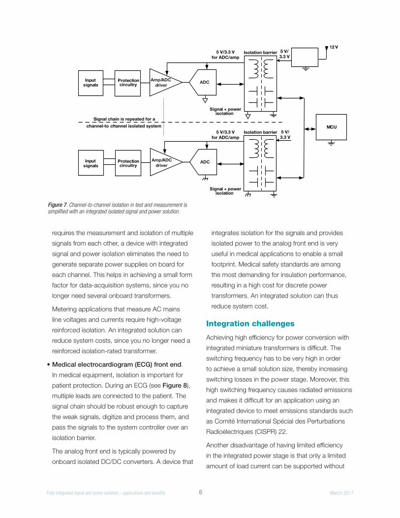
I 6 Fully integrated signal and power isolation – applications and benefits March 2017
requires the measurement and isolation of multiple
signals from each other, a device with integrated
signal and power isolation eliminates the need to
generate separate power supplies on board for
each channel. This helps in achieving a small form
factor for data-acquisition systems, since you no
longer need several onboard transformers.
Metering applications that measure AC mains
line voltages and currents require high-voltage
reinforced isolation. An integrated solution can
reduce system costs, since you no longer need a
reinforced isolation-rated transformer.
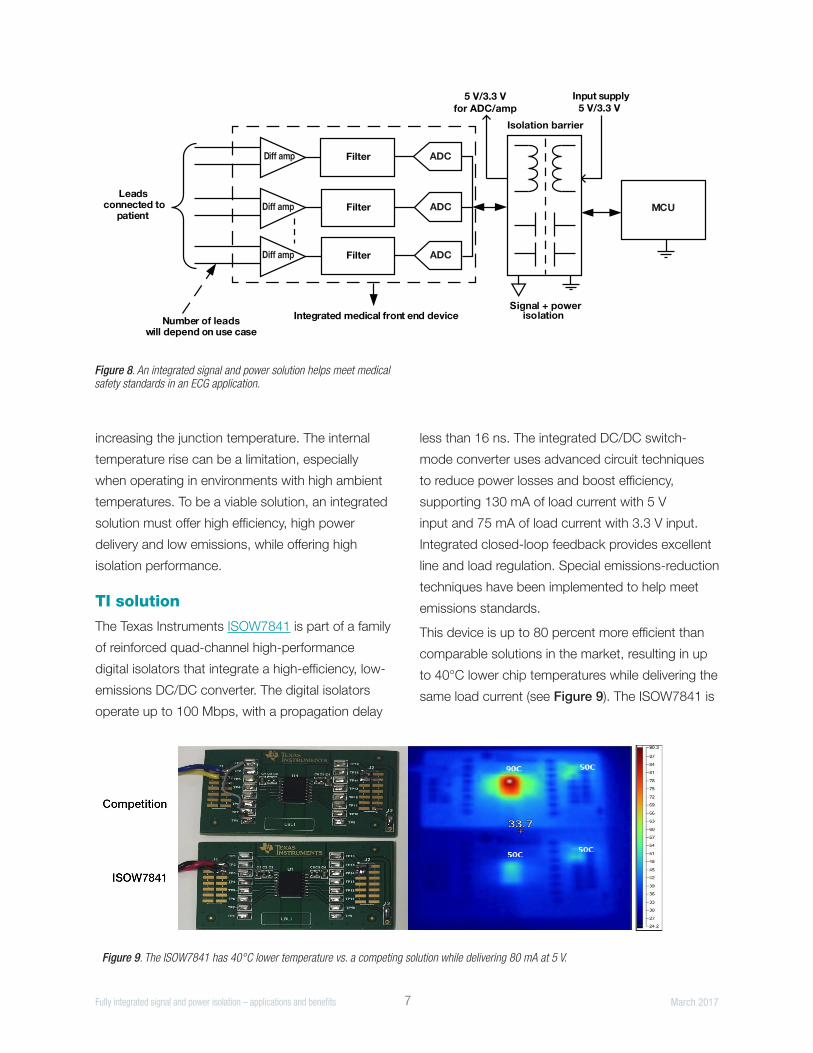
• Medical electrocardiogram (ECG) front end.
In medical equipment, isolation is important for
patient protection. During an ECG (see Figure 8),
multiple leads are connected to the patient. The
signal chain should be robust enough to capture
the weak signals, digitize and process them, and
pass the signals to the system controller over an
isolation barrier.
The analog front end is typically powered by
onboard isolated DC/DC converters. A device that
integrates isolation for the signals and provides
isolated power to the analog front end is very
useful in medical applications to enable a small
footprint. Medical safety standards are among
the most demanding for insulation performance,
resulting in a high cost for discrete power
transformers. An integrated solution can thus
reduce system cost.
Integration challenges
Achieving high efficiency for power conversion with
integrated miniature transformers is difficult. The
switching frequency has to be very high in order
to achieve a small solution size, thereby increasing
switching losses in the power stage. Moreover, this
high switching frequency causes radiated emissions
and makes it difficult for an application using an
integrated device to meet emissions standards such
as Comité International Spécial des Perturbations
Radioélectriques (CISPR) 22.
Another disadvantage of having limited efficiency
in the integrated power stage is that only a limited
amount of load current can be supported without
Figure 7. Channel-to-channel isolation in test and measurement is simplified with an integrated isolated signal and power solution.
Input signals
Protection circuitry
MCU
DC/DC converter
12 V
ADCAmp/ADC driver
ADCAmp/ADC driver
Signal chain is repeated for a
channel-to -channel isolated systemIsolation barrier
Isolation barrier5 V/3.3 Vfor ADC/amp
5 V/3.3 Vfor ADC/amp
5 V/3.3 V
5 V/3.3 V
Signal + powerisolation
Signal + powerisolation
Input signals
Protection circuitry
I 7 Fully integrated signal and power isolation – applications and benefits March 2017
increasing the junction temperature. The internal
temperature rise can be a limitation, especially
when operating in environments with high ambient
temperatures. To be a viable solution, an integrated
solution must offer high efficiency, high power
delivery and low emissions, while offering high
isolation performance.
TI solution
The Texas Instruments ISOW7841 is part of a family
of reinforced quad-channel high-performance
digital isolators that integrate a high-efficiency, low-
emissions DC/DC converter. The digital isolators
operate up to 100 Mbps, with a propagation delay
less than 16 ns. The integrated DC/DC switch-
mode converter uses advanced circuit techniques
to reduce power losses and boost efficiency,
supporting 130 mA of load current with 5 V
input and 75 mA of load current with 3.3 V input.
Integrated closed-loop feedback provides excellent
line and load regulation. Special emissions-reduction
techniques have been implemented to help meet
emissions standards.
This device is up to 80 percent more efficient than
comparable solutions in the market, resulting in up
to 40°C lower chip temperatures while delivering the
same load current (see Figure 9). The ISOW7841 is
Figure 8. An integrated signal and power solution helps meet medical safety standards in an ECG application.
ADC
MCU
FilterDiff amp
ADCFilterDiff amp
ADCFilterDiff amp
Leads connected to
patient
Input supply5 V/3.3 V
Integrated medical front end deviceNumber of leadswill depend on use case
Signal + powerisolation
5 V/3.3 Vfor ADC/amp
Isolation barrier
Figure 9. The ISOW7841 has 40°C lower temperature vs. a competing solution while delivering 80 mA at 5 V.
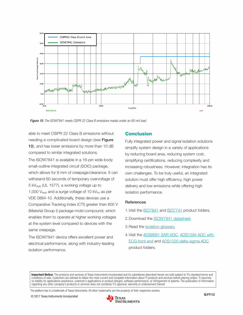
able to meet CISPR 22 Class B emissions without
needing a complicated board design (see Figure
10), and has lower emissions by more than 10 dB
compared to similar integrated solutions.
The ISOW7841 is available in a 16-pin wide-body
small-outline integrated circuit (SOIC) package,
which allows for 8 mm of creepage/clearance. It can
withstand 60 seconds of temporary overvoltage of
5 kVRMS (UL 1577), a working voltage up to
1,000 VRMS and a surge voltage of 10 kVPK as per
VDE 0884-10. Additionally, these devices use a
Comparative Tracking Index (CTI) greater than 600 V
(Material Group I) package-mold compound, which
enables them to operate at higher working voltages
at the system level compared to devices with the
same creepage.
The ISOW7841 device offers excellent power and
electrical performance, along with industry-leading
isolation performance.
Conclusion
Fully integrated power and signal isolation solutions
simplify system design in a variety of applications
by reducing board area, reducing system cost,
simplifying certifications, reducing complexity and
increasing robustness. However, integration has its
own challenges. To be truly useful, an integrated
solution must offer high efficiency, high power
delivery and low emissions while offering high
isolation performance.
References
1. Visit the ISO7841 and ISO7741 product folders.
2. Download the ISOW7841 datasheet.
3. Read the Isolation glossary.
4. Visit the ADS8681 SAR ADC, ADS1294 ADC with
ECG front end and ADS1220 delta-sigma ADC
product folders.
© 2017 Texas Instruments Incorporated SLYY112The platform bar is a trademark of Texas Instruments. All other trademarks are the property of their respective owners.
Important Notice: The products and services of Texas Instruments Incorporated and its subsidiaries described herein are sold subject to TI’s standard terms and conditions of sale. Customers are advised to obtain the most current and complete information about TI products and services before placing orders. TI assumes no liability for applications assistance, customer’s applications or product designs, software performance, or infringement of patents. The publication of information regarding any other company’s products or services does not constitute TI’s approval, warranty or endorsement thereof.
Figure 10. The ISOW7841 meets CISPR 22 Class B emissions masks under an 80 mA load.

IMPORTANT NOTICE FOR TI DESIGN INFORMATION AND RESOURCES
Texas Instruments Incorporated (‘TI”) technical, application or other design advice, services or information, including, but not limited to,reference designs and materials relating to evaluation modules, (collectively, “TI Resources”) are intended to assist designers who aredeveloping applications that incorporate TI products; by downloading, accessing or using any particular TI Resource in any way, you(individually or, if you are acting on behalf of a company, your company) agree to use it solely for this purpose and subject to the terms ofthis Notice.TI’s provision of TI Resources does not expand or otherwise alter TI’s applicable published warranties or warranty disclaimers for TIproducts, and no additional obligations or liabilities arise from TI providing such TI Resources. TI reserves the right to make corrections,enhancements, improvements and other changes to its TI Resources.You understand and agree that you remain responsible for using your independent analysis, evaluation and judgment in designing yourapplications and that you have full and exclusive responsibility to assure the safety of your applications and compliance of your applications(and of all TI products used in or for your applications) with all applicable regulations, laws and other applicable requirements. Yourepresent that, with respect to your applications, you have all the necessary expertise to create and implement safeguards that (1)anticipate dangerous consequences of failures, (2) monitor failures and their consequences, and (3) lessen the likelihood of failures thatmight cause harm and take appropriate actions. You agree that prior to using or distributing any applications that include TI products, youwill thoroughly test such applications and the functionality of such TI products as used in such applications. TI has not conducted anytesting other than that specifically described in the published documentation for a particular TI Resource.You are authorized to use, copy and modify any individual TI Resource only in connection with the development of applications that includethe TI product(s) identified in such TI Resource. NO OTHER LICENSE, EXPRESS OR IMPLIED, BY ESTOPPEL OR OTHERWISE TOANY OTHER TI INTELLECTUAL PROPERTY RIGHT, AND NO LICENSE TO ANY TECHNOLOGY OR INTELLECTUAL PROPERTYRIGHT OF TI OR ANY THIRD PARTY IS GRANTED HEREIN, including but not limited to any patent right, copyright, mask work right, orother intellectual property right relating to any combination, machine, or process in which TI products or services are used. Informationregarding or referencing third-party products or services does not constitute a license to use such products or services, or a warranty orendorsement thereof. Use of TI Resources may require a license from a third party under the patents or other intellectual property of thethird party, or a license from TI under the patents or other intellectual property of TI.TI RESOURCES ARE PROVIDED “AS IS” AND WITH ALL FAULTS. TI DISCLAIMS ALL OTHER WARRANTIES ORREPRESENTATIONS, EXPRESS OR IMPLIED, REGARDING TI RESOURCES OR USE THEREOF, INCLUDING BUT NOT LIMITED TOACCURACY OR COMPLETENESS, TITLE, ANY EPIDEMIC FAILURE WARRANTY AND ANY IMPLIED WARRANTIES OFMERCHANTABILITY, FITNESS FOR A PARTICULAR PURPOSE, AND NON-INFRINGEMENT OF ANY THIRD PARTY INTELLECTUALPROPERTY RIGHTS.TI SHALL NOT BE LIABLE FOR AND SHALL NOT DEFEND OR INDEMNIFY YOU AGAINST ANY CLAIM, INCLUDING BUT NOTLIMITED TO ANY INFRINGEMENT CLAIM THAT RELATES TO OR IS BASED ON ANY COMBINATION OF PRODUCTS EVEN IFDESCRIBED IN TI RESOURCES OR OTHERWISE. IN NO EVENT SHALL TI BE LIABLE FOR ANY ACTUAL, DIRECT, SPECIAL,COLLATERAL, INDIRECT, PUNITIVE, INCIDENTAL, CONSEQUENTIAL OR EXEMPLARY DAMAGES IN CONNECTION WITH ORARISING OUT OF TI RESOURCES OR USE THEREOF, AND REGARDLESS OF WHETHER TI HAS BEEN ADVISED OF THEPOSSIBILITY OF SUCH DAMAGES.You agree to fully indemnify TI and its representatives against any damages, costs, losses, and/or liabilities arising out of your non-compliance with the terms and provisions of this Notice.This Notice applies to TI Resources. Additional terms apply to the use and purchase of certain types of materials, TI products and services.These include; without limitation, TI’s standard terms for semiconductor products http://www.ti.com/sc/docs/stdterms.htm), evaluationmodules, and samples (http://www.ti.com/sc/docs/sampterms.htm).
Mailing Address: Texas Instruments, Post Office Box 655303, Dallas, Texas 75265Copyright © 2017, Texas Instruments Incorporated