Embed Size (px)
Citation preview

Fullwave analysis of non-contacting rotary joint choke sections using the generalised scattering matrix (GSM) approach
D.A. McNamara and L.T. Hildebrand
Abstract: An accurate fullwave analysis of waveguide (WC) rotary joint non-contacting choke sections is presented. The generalised scattering matrix (GSM) approach is used, with the constituent matrices having been obtained through a mode-matching formulation for a general waveguide bifurcation, a coaxial-to-coaxial WG junction, and a circular-to-circular WG junction. This approach is ideally suited to geometries where there are small gaps whose precise dimensions are critical for proper component operation. A detailed analysis of these components, using modem numerical modelling, does not appear to have previously been published.
1 Introduction
Waveguide rotary joints have been used in radar applica- tions for more than 50 years. Recently these components have also been used in antenna pointing mechanisms (APMs) [I, 21 for low-Earth-orbit (LEO) satellite constella- tions, and are planned for use in future systems of this kind. The latter systems require relatively large quantities of such components. There are also those space applications which call for small quantities, but for which the requirements change from one application to the next. In such applications the particular type of rotary joint selected will depend on the requirements of a specific application. Apart from obvious RF performance requirements such as banduzidth, return loss and insertion loss, there may be a maximum diameter allowed by a rotary actwator in the APM through which the rotary joint must pass. In other words, the physical compactness of the rotary joint in length and/or diameter may be a deciding Factor. The dimensional and positional tolerances (e.g. dictated by the fabrication and assembly process of the host actuator to which the separate parts of the rotary joint are attached) that must be allowed and yet ensure the required R F performance, may also steer this selection. If large quantities are needed then design to unit production cost constraints will certainly influence matters too, since the particular geometry selected by it designer will depend on the ease of fabrication. Choke geometries that would have to be electroformed (e.g. if they have re-entrant shapes) rather than machined less expen- sively on a CNC machine or by the electrical-dischargc- machining (EDM) process would typically be avoided. Furthermore, in many cases the pap sizes most desirable
0 IEE. 2003 IEE Pwccedinip online no. 20030438 dui: ID. I C49/ip-map:ZW3W3X Paper first received 5th October 2001 and in revired form l i t May 2002 D.A. McNamara and L.T. Hildsbrand were with COMDEV Lld, 155 Sheldon Drive. Camhridgc, Ontario. Calnada D.A. blcWamaw is now with the SITE. University of Oltiiwil. 161 Louis Pasteur Street. Otvawil. Ontario K I N 6NS. Canada L.T. Hildehrand is now with EMS Technologies Inc.. 21025 Trilni Canada Highway, Ste. Anne de Rellsvuu. Que& H9X 3R9, Canada
IEE Pro.-M;crow Anrenmis Propg. , Voi. I X ) , No. 1. Fehnrarv 2W3
from RF performance considerations are not feasible due to vibration, and perhaps even thermal. specifications.
Some means of accurate numerical modelling of the rotary joints is highly desirable under the described circumstances in order to take a sound decision in the midst of often conflicting demands_ and to allow design to become sufficiently routine so as to limit costs. In the case of components for which some dimensions (e.g. gaps in the choke sections of rotary joints) are very small compared to the remainder of Ihc dimensions, the use of a general- purpose finite method requires a very fine grid in the vicinity of the small dimensions, which ‘penalizes solution efficiency’ [3]. This paper describes the manner in which the general- ised scattering matrix (GSM) approach [4, 51 may be applicd to the fullwave analysis of rotary joint choke sections. This approach is ideally suited to geometries where there are both small gaps (whose precise dimensions, and small changes thereof, are critical for proper component operation) as well as larger dimensions. A detailed analysis of these components, using modern numerical modelling, docs not appear to have previously been published in the open literature.
2
A rotary joint is a two-port network that must maintain very low R F transmission loss while allowing relative mechanical rotation between the ports. This requires that the R F signal transmission between the ports be via a circularly symmetric waveguide mode. As summarised in Table 1, possibilities include linearly polarised TMol and/or T b l modes in circular waveguide, circularly polarised TEl I modes in circular waveguide, or TEM modes in coaxial waveguide. A functional block diagram of a generic rotary joint (with rectangular waveguide input/output ports assumed) is shown in Fig. 1. The mode converter launches the appropriate rotationally symmetric mode that passes through the non-contacting choke joint. A second mode converter at the far end reverses the process and provides the required rectangular waveguide output. It is the non- contacting choke that permits the relative motion between the ports.
Review of rotary joint types
5

Table 1: Classification of Some Rotarv Joints According to Rotmionally Symmetric Mode Used
rectangular waveguide
(dominant mode TElO)
cross- section -
Rotationally symmetric Mode converter type Representative Expressions for internal surface current mode used references densities (circular waveguide with no gap)
I i I non-contacting rectangular
waveguide
section (dominant
mode TE10)
waveguide of rotationally symmetric mode converter C,
(penetrates choke section)
no,>-
cross- contacting I rotaticnally
waveguide I with
mode converter Cc
I
Linearly polarised coaxial TEM Rectangular waveguide 16, p. 105, p. 110, p. 961 Jm = 0 TEIo to coaxial waveguicle TEM 19. p. 691 110. P. 3351 J = A , & l l r ~ z
Circularly polarised circular Rectangular waveguide TEla to 181 Jm = A,e*ibe*iPm~Z WG TEil circularly polarised circular J = A2eii$e*i#m,Z
WG TE,,
Linearly polarised circular Rectangular waveguide 16. p. 1051 IElll Jb = 0 J - A3e*,#m"Z
Linearly polarised circular Rectangular waveguide TEw 181. I121 Jm = A4e*iPzm' WG TMoq TEIs to circular WG TMol I -
WG TED, to circular WG TEol J, = 0
A,, are constants The 1 co-ordinate is along the waveguide axis and q4 is the azimuthal co-ordinate.
I
rotationally symmetric waveguide cross-section i rotationally symmetric
waveguide cross-section
break in mechanical contact along RF path
Fig. 1
Several types of non-contacting choke geometries have been described in the literature. some of which are recclrded in Fig. 2. It is clear from Table 1 that the wall current densities (that is, the presence of oiily a Jz component) are of the same functional form for TEM modes as for TMol. They thus excite the same types of mode in the choke sections. and so a choke that is suitable for one is suitable for the other. It is likewise evident from Table 1 that a circularly polarised TEl l mode has an as:iociated surface current density (both Jz and Jvi) that has an e*j@ variation, and it will thus not excite precisely the same modes in a choke section as do the TEM and TMol modes.' Finally. the TI& mode has no axially directed surface current density J,, and thus a small break in the waveguide can he used in place of a more geometrically complex choke. Choke dimensions that are optimum for l M i l t or TEM modes are not necessarily so for a circularly polarised TE, , mode.
Sometimes duakhannei operation is required of the rotaly joint using a single circular waveguide path. This can he achieved in a number of ways. All those reported in the literature use a separate waveguide mode (but in the same waveguide) for each of the channels. Woodward [XI mentions the use of TMol and TEoI modes, or two TEt t modes of opposite circular polarization, for this purpose, and then goes on to describe a third type of dual-channel rotary joint that uses the TMot and circularly polarised T E , , modes. In each case the mode converter has two 'isolated TE,,, mode input ports and one common port; signals applied to the two ports generate different rotationally symmetric modes at the common port. For dual-channel operation with different mode types some
Generic single-climnel mtory ,join/
6
b
e
Fig. 2 Types (a) and (b) have been described lor use with TMol and TE,, rotaryjoints [I. 2, 81. types (c) and (rr) for TMD, rotaryjoinls [6, 91 and type (e) for TEM rotary joints [9. IO. I l l . Note that these arc 'generating Cross-seCtims' in the sense that the complete rotationally symmetric geometry is formed by routing the indicated cross-section about thc axis shown. The skctchcs are for illustrative purposes only. and rclatiw dimensions should not bc taken as being accurate
Di&w choke rypes for. mrmy joinrs
IEE Proc-Microw Antennus Pmpq.. Vu/. IS#. No. I , Fdmiarj 2Ml3

Fig. 3
compromise may he requircd as far as the choke dimensions are concerned [XI.
Although the approach discussed in this pdper is applicable to all thc geometries referenced in Fig. 2, we will restrict attention to that shown in Fig. 2u and in greater detail in Fig. 3. A circularly polarised TE,, circular waveguide mode or TMol mode incident on the gap in Fig. 3 will generate coaxial waveguide modes in the coaxial waveguide section. These must be suppressed to ensure uninterrupted propagation of the R F signal in the circular waveguide. The geometry in Fig. 3 achieves this by establishing a close-to-open-circuit planc at the first corrugation and selecting the distance from this plane to thc circumferential gap to obtain ii close-to-short-circuit condition there over some required band of operation.
3
The waveguide junctions of the electromagnetic model are indicated in Fig. 3, and the model is shown schematically in terms of the required GSM modules in Fig. 4. For the choke section shown a GSM is required for: (a) circular waveguide to circular waveguide junction [S']; (b) a circular waveguide to circular waveguidejcoaxial wnvezuide bifurca- tion [SA]; and (c) coaxial waveguide to coaxial waveguide junctions [SB]. The GSM for junction (a) is well known [13],
Rolovy j(iin1 choke guunierrj
Model of the rotary joint choke that for junction (c) is available in [14, IS], while for junction (b) we havc used a generalised N-furcation version [I61 of what is essentially described for a bifurcation in [17, 41 and [IS]. Recognition here of the manner in which the N- furcation junction can be used to allow a GSM analysis of non-contacting components capable of relative mechanical rotation appears to be novel.
Use of a GSM-based model has a number of useful features. It can be used to examine the relative amplitudes of modes that are excited anywhere in the structure, which provides insight into thc operation of the rotary joint. By
allowing offsets between the waveguides comprising the junctions in the model shown in Fig. 3, it is possible to study the effects of imperfections (e.g. misalignments). This allows one to set tolerances to values no stricter than is absolutely necessary, a requirement that is particularly important in light of the fact that tightcning a tolerance even from 0.003" (0.0762mni) to 0.001" (0.0254") can increase the cost of a machining operation significantly. It is also possible 10 incorporate the GSMs of the remainder of the components (e.g. mode converters, WG transformers) in the cascade comprising the complete rotary joint, and thus to sludy the overall performance (e.g. detemiine whether there are trapped mode resonances). Rotary joints must have very low insertion loss. The latter is non-zero due to dissipative losses in the walls of the guiding structure, mode conversion, and reflection loss effects. The GSM approach allows one to examine mode conversion effects with relative ease. Since the choke sections are just one part of a cascade of components (see Fig. I) comprising thc rotary joint they need to be so designed that they have an excellent retum loss over the operating band in question. The GSM approach is ideal for reliably predicting such low reflection levels.
4 Experimental and theoretical results
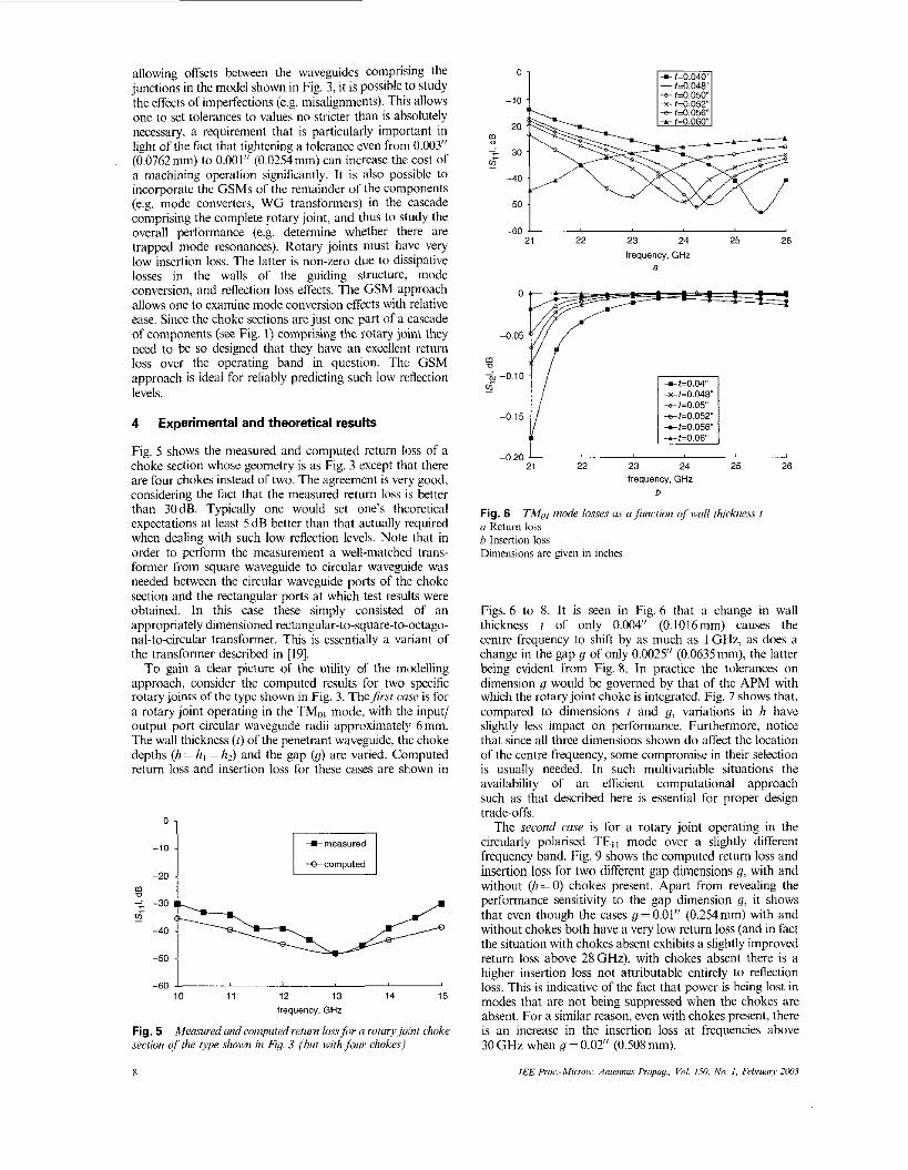
Fig. 5 shows the measured and computed retum loss of a choke Section whose geometry is as Fig. 3 except that there are four chokes instead of two. The agreement is very good, considering the fact that the measured return loss is better than 30dB. Typically one would set one's theoretical expectations at least 5dB better than that actually required when dealing with such low reflection levels. Note that in order to perform the mcasurement a well-matched trans- former from square waveguide to circular waveguide was needed between the circular waveguide ports of the choke section and the rectangular ports at which test results were obtained. In this case these simply consisted of an appropriately dimensioned rectangular-to-square-to-octago- nal-to-circular transformer. This is essentially a variant of the transformer described in [19].
To gain a clear picture of the utility of the modelling approach, consider the computed results for two specific rotary joints of the type shown in Fig. 3. Thefirst cuse is for a rotary joint operating in the TM,,, mode, with the input/ output port circular waveguide radii approximately 6". The wall thickness ( 2 ) of the penetrant waveguide, the choke depths (h= h, =h2) and the gap (g) are varied. Computed retum loss and insertion loss for these cases are shown in
0
-20 - lo 1 10 1 1 12 13 14 15
frequency. GHz
Mcamredund computed return l a s s f i r N rorur,v joint choke Fig. 5 section of the type sho~vn in Fiq. 3 (hut wirli four chokes)
8
0
-10
-20
-: -30 1
i -40
-50
-60 21 22 23 24 25 26
frequency, GHr a
0
+t=0.048' e t = 0 . 0 5 +t=0.052'
25 26 -0.20 1
21 22 23 24 frequency, GHz
b
Fig. 6 <I Retom loss b lnsenion loss Dimensions are giwn in inches
TM,,, iiiode losses CY u function of iwll rhickness I
Figs. 6 to 8. It is seen in Fig. 6 that a change in wall thickness t of only 0.004" (0.1016mm) causes the centre frequency to shift by as much as 1 GHz, as does a change i n the gap y of only 0.0025" (0.0635"). the latter being evident from Fig. 8. In practice the tolerances on dimension g would be governed by that of the APM with which the rotary joint choke is integrated. Fig. 7 shows that. compared to dimensions f and g. variations in !I have slightly less impact on performance. Furthermore. notice that since all thrce dimensions shown do affect the location of the centre frequency, some compromise in their selection is usually needed. In such multivariahle situations the availability of an efficient computational approach such as that described here is essential for proper design trade-offs.
The second case is for a rotary joint operating in the circularly polarised TE, , mode over a slightly diffcrcnt frequency band. Fig. 9 shows the computed return loss and insertion loss for two different gap dimensions 8. with and without (11 = 0) chokes present. Apart from revealing the performance sensitivity to the gap dimension y, it shows that even though the cases g=O.O1" (0.254mm) with and without chokes both have a very low return loss (and in fact the situation with chokes absent exhibits a slightly improved return loss above 28 GHz), with chokes absent there is a higher insertion loss not attributable entirely to reflection loss. This is indicative of the fact that power is being lost in modes that are not being suppressed when the chokes are absent. For a similar reason, even with chokes present. there is an increase in the insertion loss at frequencies above 30GHz when y= 0.02" (0.508mm).
IEE Pruc.-Mi<mii: A , i l c m ~ s P r u p g . . Vol. 150, h'o. 1. l+bruur). ZW3

-h=0.144"
-o,25.
-60 2
21 22 23 24 25 26 frequency, GHz
a
0
-0.05
-0.10
1 -0.15
.? ""- -
+g=O.OY with chokes +g=O.Ol" with chokes
+g=O.OZ without chokes -Cg=O.Ol" without chokes
I
1 Y, -".CY -
-0.25
4 -0.30
-0.35 21 22 23 24 25 26
frequency, GHz b
Fig. 7 U Returu loss h Insertion loss Dimensions are given in inches
TM,,) i,iodc. Imw as u,/iurcrioii of choke heighr h
0
-10
-20 m D - -30 5
-40
-50
"" 21 22 23 24 25 26
frequency. GHz
Fig. 8 ciimensiun 9 Dimensions are giwn in inches
Retrrrn I m of tlte TMcil mode ay U jrnction of gap
In all the above results perfcct conductors have been assumed in the GSM-based models. Although results have not been presentcd that show the effcct of lateral asymmetries (only axial misalignment effects were consid- ered through observation of the consequenccs of altering 9). this is possible using the GSM-based approach discussed if the individual GSM modules have been developed to account for this.
/E€ Pruc-Micros,. Ariiennus Propug., Vol. 150, No. I , February 21M3
0 +-g=O.OZ with chokes -e-g=O.Ol" with chokes
+g=O.OZ without chokes +g=O.Ol" withod chokes
g -201
-60 18 20 22 24 26 28 30 32
frequency. GHz a
0
-0.05
5 Conclusions
An accurate fullwave analysis of rotary joint non-conhcting choke sections has been presented. Suggestions for a detailed analysis of these components do not appear to have been published previously in the open literature. The generalised scattering matrix approach is used, with novel use being made of the generalised waveguide N-furcation formulation to model non-contacting components capable of relative mechanical movement. A comparison of some computed and measured results has been shown, along with an indication of the utility of the method in generating performance data capable of guiding the selection of both nominal dimensions and setting critical tolerances. The approach described has been applied to the analysis of rotary joints successfully produced and in use in commercial satellite hardware.
6 Acknowledgments
Most of the work on which this paper is based was done while the authors were with COMDEV Ltd, Ontario, Canada, and is published with its permission.
7 References
I LECKIE, M., and LAIDIG, D.: 'Development o f a gimhaled, dual frequency, space-based, microwave antenna for volume production'. 30th Aerosmce Mechanism Svmoosium. NASA Lanelcv Research
' .I... .. .. . dual frequency. satellite microwwe sntcnna'. PrOc. Symp. on antenna tcchndogy & 2lpplied eleclromagnetics (ANTEM.96) Montreal. Qucbec. Canada. looL --
3 ZHU. Y.. and CAI I,". yp. W l - Y Y l
VGELLARIS. A.C.: 'Macro~clcmeni for efficient FEM simulation of small geometric features in waveguide campo- ncnts'. IEEE Trans. MICTOM: Theory Tech, 2000, M T T 4 , (12). pp. 2254-2260 UHER, J., BORNEMANN, 1.. and ROSENBERG, U.: 'Waveguide Components for Antenna Fecd Systems' (Armh House Inc, 1993)
4
9

5 FOSTER. P.R.. and TUN. S.M.: 'Modelling Waveguide Conpanents using Mode-Matching Techniques', Mirron. Emg EEK, April 1996
6 RAGAN. G.L. (Ed.): 'Microwave Transinission Circuits' (McGraw~ Hill. 1948)
7 MONTGOMERY. C.C.. DICKE, R.H. and FURCELL. E.M. (Eds.): 'Principles of Microiiavc Circuits' (McCraw-Hill. 1948)
8 WOODWARD, O.M.: 'A dual-chimncl rotary joint for high average pow'er operation'. 1EEE Trm.s. Microw 7 k w y Ted?.. 1970. rWIT-18,
9 HELSZAJN, 1.: 'Passive ;md Active Microwave Circuit:,' (Wiley, 1978). pp. 68-69
10 RIZZI. P.A.: 'Microwax Enginering: Passivc Circuits' (Pientice- H;dI. 1988)
I 1 Rotary Joints Cat;ilogue, Kevlin Coipowlion. Wilminglon. Masia- chusetts, USA
12 SIMMONS, A.J.: 'TE,,, mode components in the 3-mm region'. IEEE 7rom Microw Thcwry Tedz.. 1963. MTT-9. (9). pp. 324-332
13 PAPALINER. U,, m d ARNDT. F.: 'Field thcuictical computer- aided design of rectangular and circular ins coupled rectangular or circular waveguide cavity filters'. IEEE T w n s Miwow. Tlmry Tech.. 1993. MTT-II. (3). pp. 462471
(12), pp. 1072-1077
14 LAWSON, W.. and LATHAM, P.E.: 'The ~cattenng matrix formulation for ovemodrd axid id cavities'. 1EEE Tram Micron:
15 ORFANIDIS. A.P.. KYRIACOU, G.A.. and SAHALOS. J.N.: 'A mode-matching technique for the study of circular and coilx\iill wawguide discontinuities hared on c losd fomi coupling in1egr;ds'.
M ~ ~ ~ w 7 7 ~ 0 r y RVII.. 2000. M T T ~ , (51, pp. 8x0-8x3 16 WU. K.: Dep;mment of Electronic Engineering, The Chinese
Uniwrsity of Hong Koog. Hong Kong. Pnvatc Communication. (Fumerly with COM DEV Ltd.. Onlaio. Canada)
'Solution of wavcguidc discontinuitics by modal ' l i w ~ s . Mirron: T h r j Ted., 1967. MTT-15. (9).
18 TUN. S.M.: 'Modc matching annlysis of combincd nrculai and cwaxial structum loaded with dielectrics'. I'roceedingc of Int. Conf. on Compulations in clcctramagnelics. London. UK. 2%27 Nov. 1991. (IEE Conf. Puhl. No. 350), pp. 230-233
19 BATHKER. D.A.: 'A stepped mode transducer using homogeneous w.lveguidcs', IEEE T ~ ~ , ~ . ~ , ~ i c ~ ~ ~ t v . Tilmn. E,?/,., 1967. MTT-16. (2). pp. IZX-130
riZeorj, T& 1992. ma, (in). pp. 1973-1977
IEEE
pp. 50~517
I O