Embed Size (px)
Citation preview
Installation Guide
Fuller Advantage™ Manual TransmissionTRIG0970 EN-USApril 2014
Table of Contents
Introduction and General Information Warnings and Cautions ................................................................................................................................ 1Important Notice .......................................................................................................................................... 1About This Manual ...................................................................................................................................... 2OEM Design Responsibility .......................................................................................................................... 2Application Approval .................................................................................................................................... 2Transmission Identification Tag ................................................................................................................... 3Product Identification................................................................................................................................... 3Product Familiarization ................................................................................................................................ 4Similarities and Differences Compared to Current Manual Products............................................................ 4Suggested Tools/Publications ..................................................................................................................... 5Vendor List................................................................................................................................................... 5
Vehicle Space ClaimShift Label Requirements ............................................................................................................................. 6Shift Levers .................................................................................................................................................. 7Fuller Advantage 10-Speed .......................................................................................................................... 8
Clutch InterfacePilot Bearing Specifications.......................................................................................................................... 10Grease Hose................................................................................................................................................. 10
Transmission InterfaceClutch Housings........................................................................................................................................... 11Top View ...................................................................................................................................................... 13Side View ..................................................................................................................................................... 14Handling....................................................................................................................................................... 15Transmission Preparations .......................................................................................................................... 15Reverse and Neutral Switches...................................................................................................................... 15End Yoke Retaining Design .......................................................................................................................... 16Output Speed Sensor - Push In.................................................................................................................... 16Mounting Transmission to Engine ............................................................................................................... 17Using Rear Supports.................................................................................................................................... 17Air Supply and Air Drying Requirements...................................................................................................... 18Lubrication Requirements and Specifications .............................................................................................. 19Operating Temperatures and Cooling Requirements.................................................................................... 19Transmission Oil Level ................................................................................................................................. 20
AppendixTorque Specifications .................................................................................................................................. 21Design Remedies for Shift Lever Jumpout................................................................................................... 22Change Control Log .................................................................................................................................... 24
1
Warnings and CautionsW
arnings and Cautions
Introduction and General Information
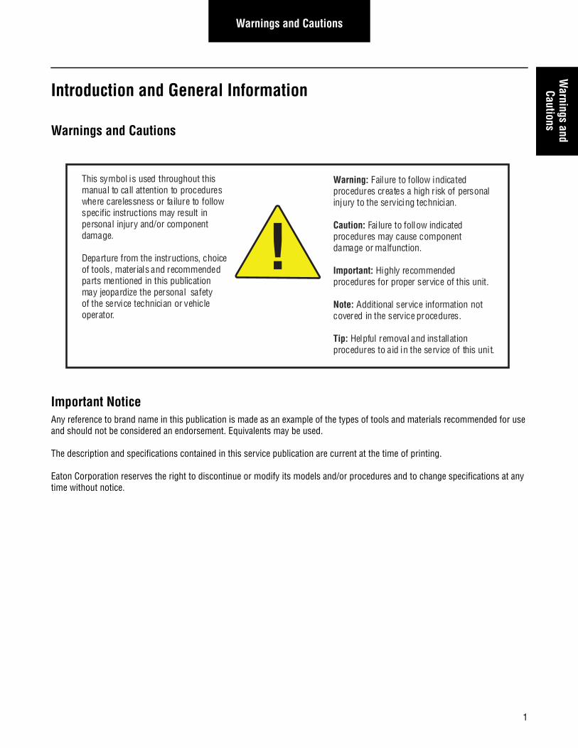
Warnings and Cautions
Important NoticeAny reference to brand name in this publication is made as an example of the types of tools and materials recommended for use and should not be considered an endorsement. Equivalents may be used.
The description and specifications contained in this service publication are current at the time of printing.
Eaton Corporation reserves the right to discontinue or modify its models and/or procedures and to change specifications at any time without notice.
This symbol is used throughout this manual to call attention to procedures where carelessness or failure to follow specific instructions may result in personal injury and/or component damage.
Departure from the instructions, choice of tools, mater ials and recommended parts mentioned in this publication may jeopardize the personal safety of the service technician or vehicle operator.
Warning: Failure to follow indicated procedures creates a high r isk of personal injury to the servicing technician.
Caution: Failure to follow indicated procedures may cause component damage or malfunction.
Important: Highly recommended procedures for proper service of this unit.
Note: Additional service information not covered in the service procedures.
Tip: Helpful removal and installation procedures to aid in the service of this uni t.
!
2
General Information
About This Manual
This Eaton® publication is intended to be a reference guide for the installation of manual shift Fuller® Advantage transmissions. General vehicle and transmission information is provided to cover the wide range of applications. This information benefits the OEM installer by providing the correct installation procedures to ensure the utmost in satisfactory operation and long service life. For additional transmission information, see the Suggested Tools section in this manual. For specific engine information contact the engine OEM.
Failure to adhere to Eaton Installation Requirements may affect transmission performance and/or warranty coverage.
Transmissions installed at OEM facilities shall meet and be approved by Eaton Application Engineering. Contact Eaton Application Engineering or your OEM Application Engineering department for the proper Application form.
OEM Design ResponsibilityOEM facilities shall submit a design package to Eaton Corporation OEM Engineering Support Group for approval prior to any OEM build. A design package consists of the following information.
Transmission air supply: Source of air supply and routing and clipping of air supply line.
Transmission cooling system: Cooler type and capacity, cooler hose(s) routing and clipping.
Individual harness drawings: Construction detail of individual wiring harnesses including harness routing location and clipping points.
Wiring schematic: High-level schematic of how this transmission interfaces with the vehicle.
Application ApprovalFuller Advantage model transmission systems installed at OEM facilities must meet the requirements as defined in TRAG2600. If your application does not meet these requirements you must submit an approval to Eaton Application Engineering as defined in TRAG2600.
• Driveline Torque Requirements - Driveline angular acceleration and driveline torque shall not exceed requirements stated in Eaton Application Guideline specification TRAG2600.
• Applications and PTO Applications- refer to Application Guidelines Manual TRAG2600 and TRIG2600 for PTO applica-tion guidelines.
Every effort has been made to ensure the accuracy of the information contained in this manual. However, Eaton Corporation makes no warranty, either expressed or implied, based on the information provided. With each new application, engine manufac-tures should be contacted to make sure desired engines are compatible with these systems.
3
General InformationGeneral
Information
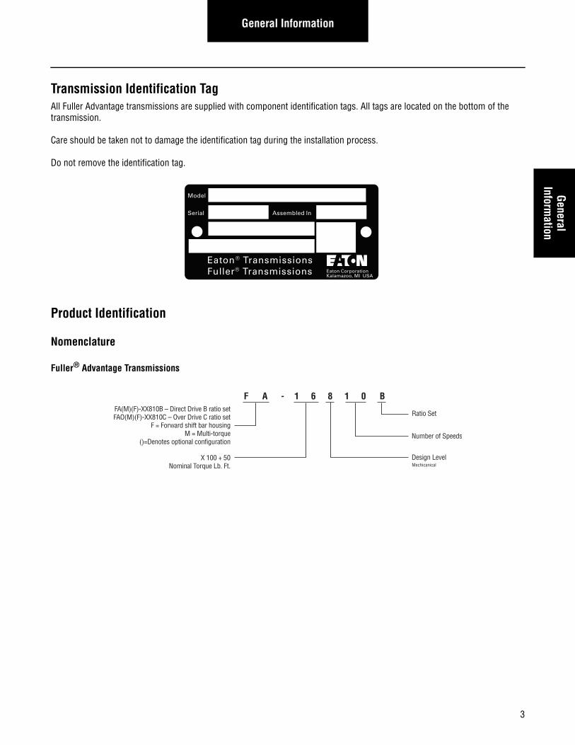
Transmission Identification TagAll Fuller Advantage transmissions are supplied with component identification tags. All tags are located on the bottom of the transmission.
Care should be taken not to damage the identification tag during the installation process.
Do not remove the identification tag.
Product Identification
Nomenclature
Fuller® Advantage Transmissions
Eaton® TransmissionsFuller® Transmissions
Model
Serial Assembled In
Eaton CorporationKalamazoo, MI USA
F FA(M)(F)-XX810B – Direct Drive B ratio setFAO(M)(F)-XX810C – Over Drive C ratio set
F = Forward shift bar housingM = Multi-torque
()=Denotes optional configuration
A -
X 100 + 50Nominal Torque Lb. Ft.
Ratio Set
Number of Speeds
1 6 8 1 0 B
Design LevelMechicanical
4
General Information
Product Familiarization
Similarities and Differences Compared to Current Manual ProductsNote: In all cases where differences have been identified, see the respective installation requirements for details.
Similarities with Fuller® RT/FR/FRO Manual Transmission Products
• Identical PTO locations and PTO fit up requirements
• Identical shift tower options
• Compatible with existing Fuller RT clutch housings with pressure lube system
• Compatible withe existing SRC and LRC shift devices
• Shift lever travel is the same as current RT products
• Site glass same as RT
• Pump port is same location as RT
Differences and Features with Fuller® RT/FR/FRO Manual Transmission Products
• Oil sump protrusion on the bottom of the transmission main case
• Aluminum shift bar housing
• Aluminum range and bearing covers
• O-ring seal for shift tower to shift bar housing interface
• Cooler is not required on some applications. See TRAG2600 for details
• Shift lever travel is greater than FR/FRO series
• Fuller Advantage has imperial fasteners vs. FR with metric
• Through-shaft PTO is only available in the lower left location
• Temperature sensor is in the right rear
• Aluminum back box cover
5
General InformationGeneral
Information
Suggested Tools/Publications
Vendor List
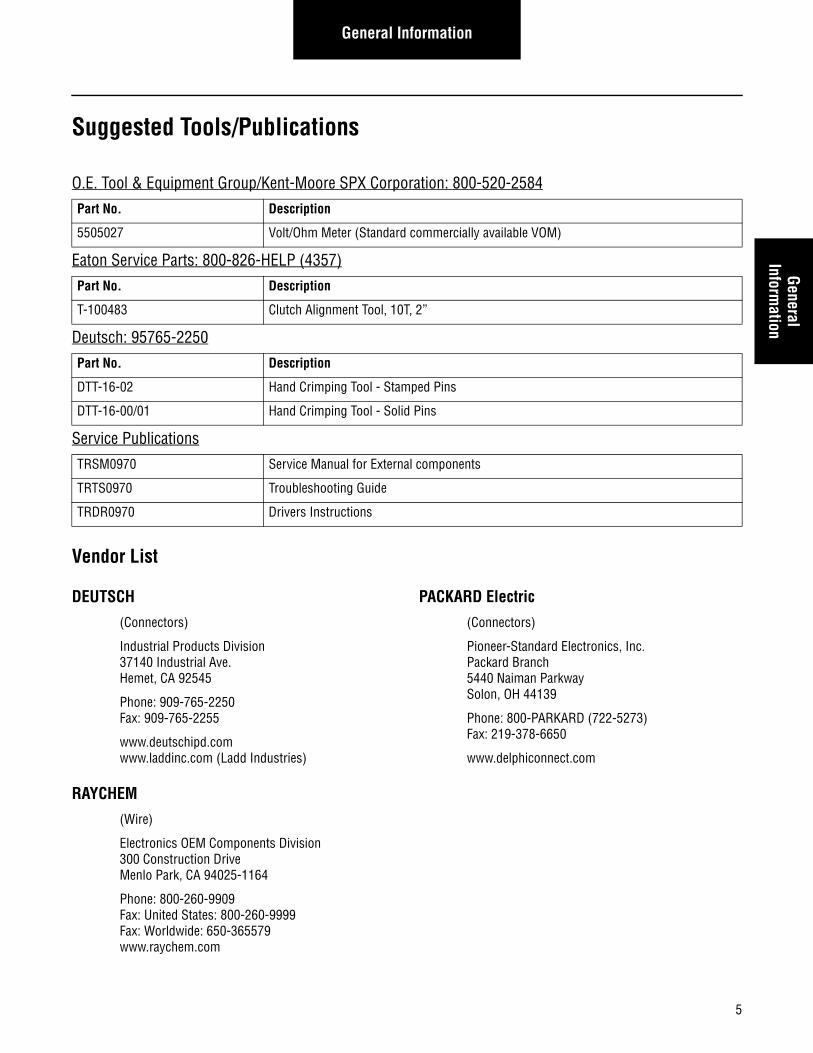
DEUTSCH
(Connectors)
Industrial Products Division37140 Industrial Ave.Hemet, CA 92545
Phone: 909-765-2250Fax: 909-765-2255
www.deutschipd.comwww.laddinc.com (Ladd Industries)
PACKARD Electric
(Connectors)
Pioneer-Standard Electronics, Inc.Packard Branch5440 Naiman ParkwaySolon, OH 44139
Phone: 800-PARKARD (722-5273)Fax: 219-378-6650
www.delphiconnect.com
RAYCHEM
(Wire)
Electronics OEM Components Division300 Construction DriveMenlo Park, CA 94025-1164
Phone: 800-260-9909Fax: United States: 800-260-9999Fax: Worldwide: 650-365579www.raychem.com
O.E. Tool & Equipment Group/Kent-Moore SPX Corporation: 800-520-2584
Part No. Description
5505027 Volt/Ohm Meter (Standard commercially available VOM)
Eaton Service Parts: 800-826-HELP (4357)
Part No. Description
T-100483 Clutch Alignment Tool, 10T, 2”
Deutsch: 95765-2250
Part No. Description
DTT-16-02 Hand Crimping Tool - Stamped Pins
DTT-16-00/01 Hand Crimping Tool - Solid Pins
Service Publications
TRSM0970 Service Manual for External components
TRTS0970 Troubleshooting Guide
TRDR0970 Drivers Instructions
6
Vehicle Space Claim
Vehicle Space Claim
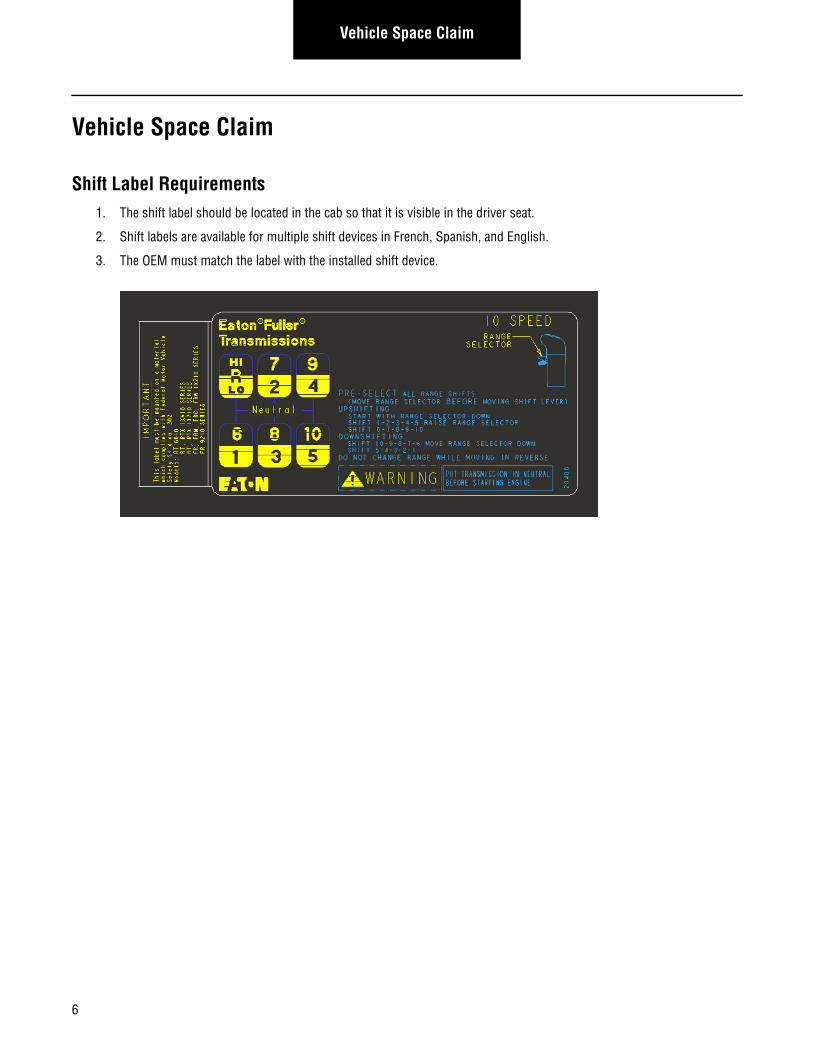
Shift Label Requirements1. The shift label should be located in the cab so that it is visible in the driver seat.
2. Shift labels are available for multiple shift devices in French, Spanish, and English.
3. The OEM must match the label with the installed shift device.
7
Vehicle Space ClaimVehicle Space
Claim
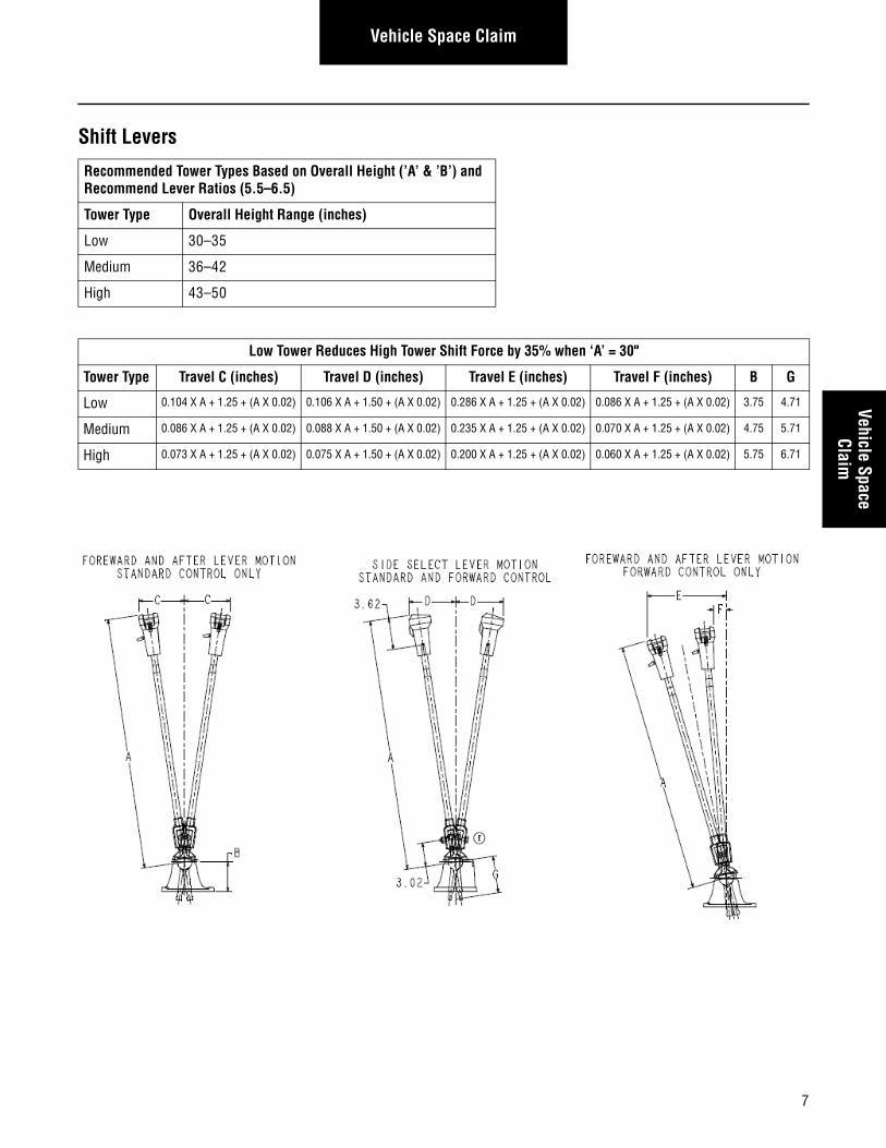
Shift Levers
Recommended Tower Types Based on Overall Height (’A’ & ’B’) and Recommend Lever Ratios (5.5–6.5)
Tower Type Overall Height Range (inches)
Low 30–35
Medium 36–42
High 43–50
Low Tower Reduces High Tower Shift Force by 35% when ‘A’ = 30"
Tower Type Travel C (inches) Travel D (inches) Travel E (inches) Travel F (inches) B G
Low 0.104 X A + 1.25 + (A X 0.02) 0.106 X A + 1.50 + (A X 0.02) 0.286 X A + 1.25 + (A X 0.02) 0.086 X A + 1.25 + (A X 0.02) 3.75 4.71
Medium 0.086 X A + 1.25 + (A X 0.02) 0.088 X A + 1.50 + (A X 0.02) 0.235 X A + 1.25 + (A X 0.02) 0.070 X A + 1.25 + (A X 0.02) 4.75 5.71
High 0.073 X A + 1.25 + (A X 0.02) 0.075 X A + 1.50 + (A X 0.02) 0.200 X A + 1.25 + (A X 0.02) 0.060 X A + 1.25 + (A X 0.02) 5.75 6.71
8
Vehicle Space Claim
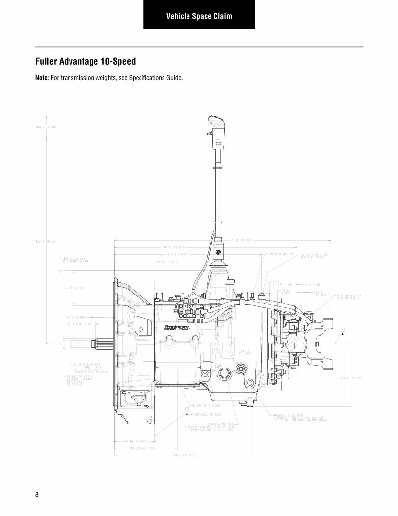
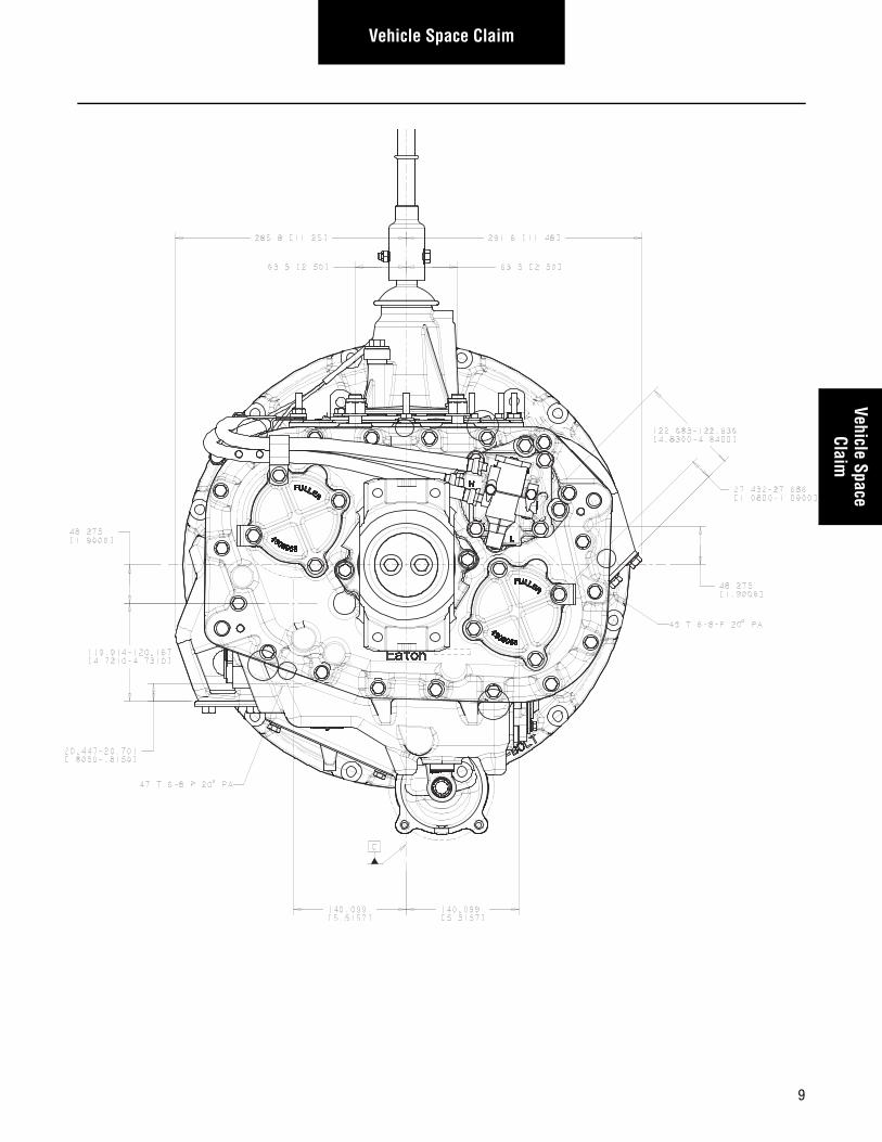
Fuller Advantage 10-Speed
Note: For transmission weights, see Specifications Guide.
9
Vehicle Space ClaimVehicle Space
Claim
10
Clutch Interface
Clutch Interface
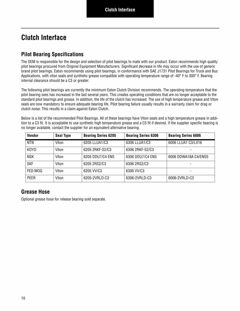
Pilot Bearing SpecificationsThe OEM is responsible for the design and selection of pilot bearings to mate with our product. Eaton recommends high quality pilot bearings procured from Original Equipment Manufacturers. Significant decrease in life may occur with the use of generic brand pilot bearings. Eaton recommends using pilot bearings, in conformance with SAE J1731 Pilot Bearings for Truck and Bus Applications, with viton seals and synthetic grease compatible with operating temperature range of -40° F to 300° F. Bearing internal clearance should be a C3 or greater.
The following pilot bearings are currently the minimum Eaton Clutch Division recommends. The operating temperature that the pilot bearing sees has increased in the last several years. This creates operating conditions that are no longer acceptable to the standard pilot bearings and grease. In addition, the life of the clutch has increased. The use of high temperature grease and Viton seals are now mandatory to ensure adequate bearing life. Pilot bearing failure usually results in a warranty claim for drag or clutch noise. This results in a claim against Eaton Clutch.
Below is a list of the recommended Pilot Bearings. All of these bearings have Viton seals and a high temperature grease in addi-tion to a C3 fit. It is acceptable to use synthetic high temperature grease and a C5 fit if desired. If the supplier specific bearing is no longer available, contact the supplier for an equivalent alternative bearing.
Grease HoseOptional grease hose for release bearing sold separate.
Vendor Seal Type Bearing Series 6205 Bearing Series 6306 Bearing Series 6006
NTN Viton 6205 LLUA1/C3 6306 LLUA1/C3 6006 LLUA1 C3/LX16
KOYO Viton 6205 2RKF-S2/C3 6306 2RKF-S2/C3 -
NSK Viton 6205 DDU7/C4 ENS 6306 DDU7/C4 ENS 6006 DDWA18A C4/ENSS
SKF Viton 6205 2RS2/C3 6306 2RS2/C3 -
FED-MOG Viton 6205 VV/C3 6306 VV/C3 -
PEER Viton 6205-2VRLD-C3 6306-2VRLD-C3 6006-2VRLD-C3
11
Transmission InterfaceTransm
ission Interface
Transmission Interface
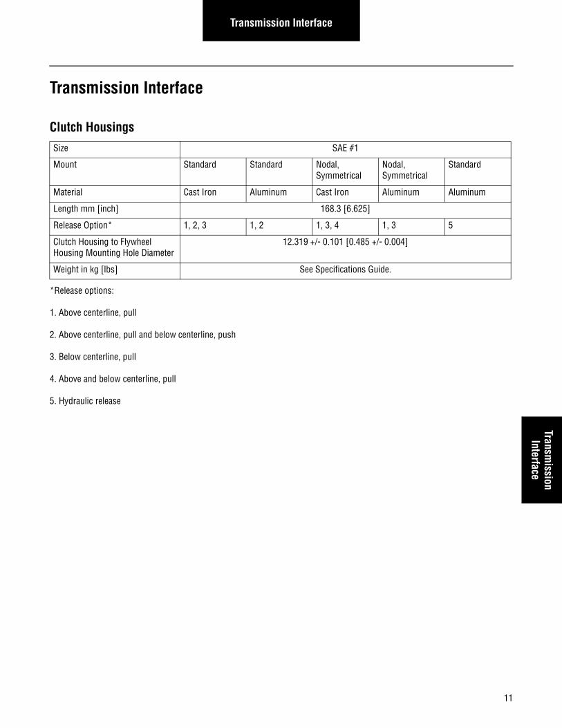
Clutch Housings
*Release options:
1. Above centerline, pull
2. Above centerline, pull and below centerline, push
3. Below centerline, pull
4. Above and below centerline, pull
5. Hydraulic release
Size SAE #1
Mount Standard Standard Nodal, Symmetrical
Nodal, Symmetrical
Standard
Material Cast Iron Aluminum Cast Iron Aluminum Aluminum
Length mm [inch] 168.3 [6.625]
Release Option* 1, 2, 3 1, 2 1, 3, 4 1, 3 5
Clutch Housing to Flywheel Housing Mounting Hole Diameter
12.319 +/- 0.101 [0.485 +/- 0.004]
Weight in kg [lbs] See Specifications Guide.
12
Transmission Interface
A
C
B
30
12BOLT
SPACING
95.25[3.750]
209.55[8.25]
NODALMOUNT
60.325[2.375]
111.125[4.375]
168.275[6.625]
BELOWPULLCL
BELOWPUSHCL
ABOVEPULLCL
38.1[1.500]
38.1[1.500]
Fig. 1 Fig. 215
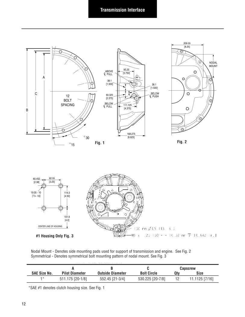
Nodal Mount - Denotes side mounting pads used for support of transmission and engine. See Fig. 2Symmetrical - Denotes symmetrical bolt mounting pattern of nodal mount. See Fig. 3
A B C CapscrewSAE Size No. Pilot Diameter Outside Diameter Bolt Circle Qty Size
1* 511.175 [20-1/8] 552.45 [21-3/4] 530.225 [20-7/8] 12 11.1125 [7/16]
*SAE #1 denotes clutch housing size. See Fig. 1
#1 Housing Only Fig. 3
60.452[2.38]
19.05 - 10 [ ]
82.55[3.25]
114.3[4.50]-10/43
101.6[4.0]
CENTER LINE OF HOUSING
13
Transmission InterfaceTransm
ission Interface
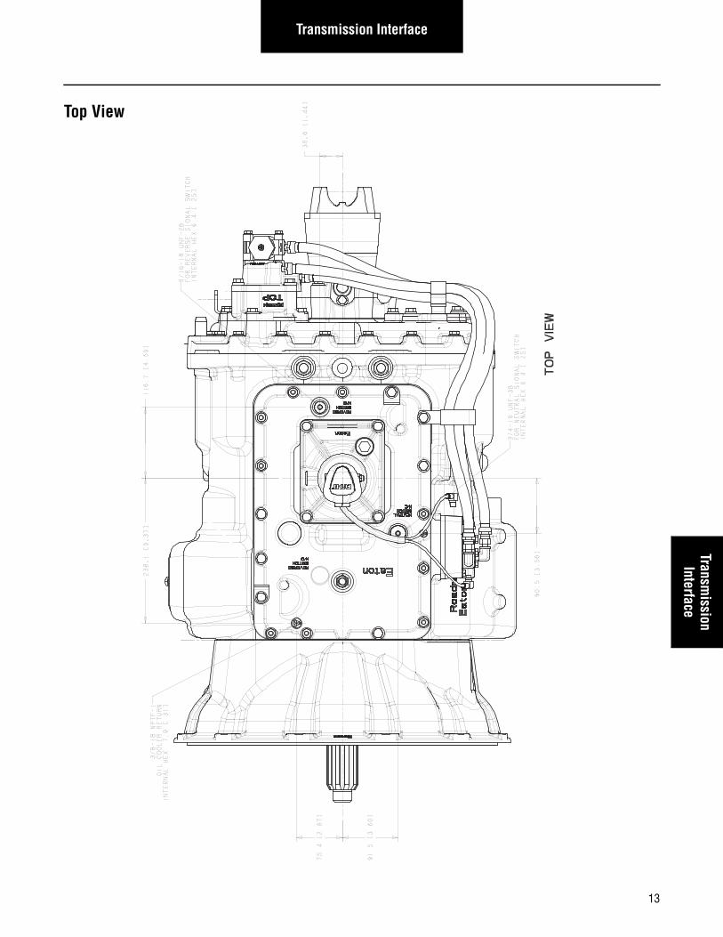
Top View
14
Transmission Interface
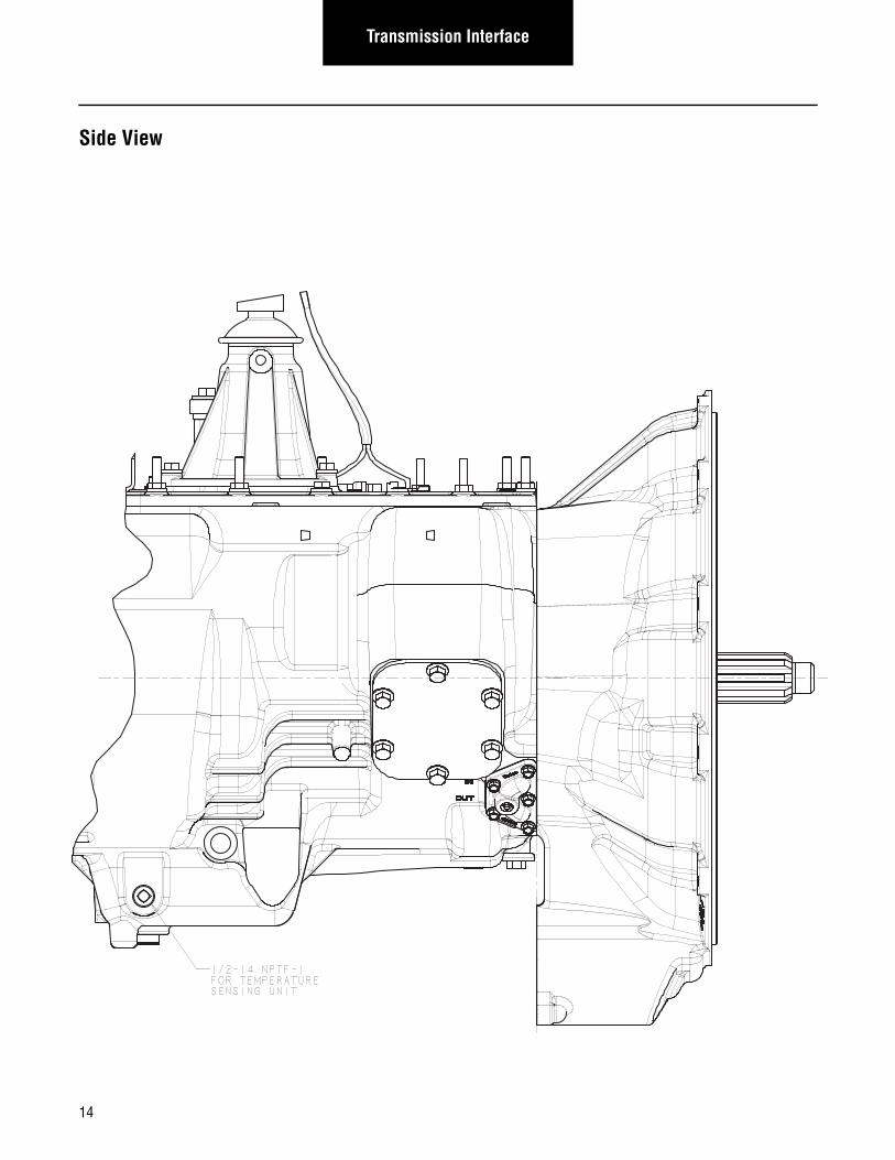
Side View
15
Transmission InterfaceTransm
ission Interface
HandlingHandle the transmission carefully to avoid damage to the transmission components and surrounding vehicle components.
• Use a hoist or transmission jack that permits precise control of the transmission movement during installation.
Transmission PreparationsNote: Eaton has provided several double-ended studs that can be used for attaching vehicle components to. Sensor and lifting
eye fasteners are not to be used for securing additional OEM brackets under any circumstances. This includes cap screws used to fasten the shift bar housing, rear housing, bearing covers, and PTO covers. The Fuller Advantage utilizes a different sealing method than previous models of Fuller transmissions. Therefore, it is imperative that bolts are not removed from the shift bar housing and rear plate of the transmission.
Note: No mechanical speedometer.
Reverse and Neutral Switches
Switch OptionsReverse and neutral switch openings are standard on all heavy duty Fuller transmissions. The transmission will be shipped with plugs in these openings, unless switches are ordered by the OEM and pre-installed by Eaton.
Reverse Switches
Supply Voltage 12V System (9V–16V)
24V System (16V–32V)
Switching Currents 10 amps for 12V circuit
3 amps for 24V Circuit
Sensor Loads < 1 amp for 12V or 24V
Switch State Normally Closed
Thread 0.5625-18 UNF-2B
Wrench Size 7/8
Part Number 4304808
Mating Connector Information Weather Pack PN
Connector Assembly Part Number 12015378
Terminal (Qty. of 2 required) 12124582
Cable Seal (Qty. of 2 required) 12010293
Part Number 22940
Connector Type Screw
Screw Terminal Details 2 x 8-32 x 0.25 in. with #8 internal lock washer
16
Transmission Interface
Neutral Switches
End Yoke Retaining DesignAll Fuller Advantage model transmissions have a two bolt retainer plate design that retains the end yoke. The Fuller Advantage transmission will be shipped with the end yoke installed. In the event that a yoke needs to be re-installed, special care should be exercised to snug each bolt to 35 ft-lbs prior to attaining full torque of 84–92 ft-lbs. For reference, these bolts are M12 x 1.25 x 60 mm Grade 10.9 per DIN 6921.
Output Speed Sensor - Push In
Note: Need both Packard Assembly and Packard Sockets for proper wiring harness interface.
Thread 0.750-16 UNF-2A
Wrench Size 7/8
Part Number 4304809
Connector Type Weather Pack
Mating Connector Information Weather Pack Part Number
Connector Assembly Part Number 12015378
Terminal (Qty. of 2 required) 12124582
Cable Seal (Qty. of 2 required) 12010293
Part Number 22941
Connector Type Screw
Screw Terminal Details 2 x 8-32 x 0.25 in. with #8 internal lock washer
Eaton Part Number 4307349 4307353
Output Type Single Dual
Packard Connector Information to Mate to Eaton Sensor
Packard Assembly Number** 12162193 12162188
Packard Connector Body* 12162192 12162187
Packard Connector Seal* 12040751 12040757
Packard Cable Seal* 12040751 12040757
Packard Socket Number (Quantity)** 12124075 (4) 12124075 (2)
Connector Pinouts: Pin “A” Positive Terminal Positive Terminal Coil 1
Pin “B” Negative Terminal Negative Terminal Coil 1
Pin “C” N/A Positive Terminal Coil 2
Pin “D” N/A Negative Terminal Coil 2
*Used To Make Packard Assembly**Need both Packard Assembly and Packard Sockets for proper wiring harness interface.
Rotor Number of teeth 16 teeth
Sensor Clock positions 10 and 12 o’clock or 4 and 6 o’clock
Type Variable reluctance push-in
Connector supplier Packard metri-pack 150
Output voltage/air gap 0.3 Vp-p (min) 0.01" to 0.09"
Sensor inductance 0.6–3.7 henries with an input signal of 1kHz @ 1 Vpk-pk
17
Transmission InterfaceTransm
ission Interface
Mounting Transmission to EngineUse the two transmission lifting eyes provided. The lifting eye position shall not be changed on the transmission.
• Use a two point lift chain or transmission jack with a minimum capacity of 1500 lbs.
• Inspect the engine to transmission mating surfaces for damage or debris prior to installation. Make sure the engine fly-wheel housing face, transmission clutch housing face, input shaft, etc. are free of paint, debris, rust, and any type of damage before installation.
• Input Shaft To Clutch Alignment - Engaging the transmission into gear will allow for the rotation of the input shaft by rotating the output shaft/yoke.
• Adjust the lift chain or transmission jack to obtain the same relative angle as the engine. The face of the engine flywheel housing and the face of the transmission clutch housing shall be parallel during installation. Rotate the output shaft/yoke while sliding the input shaft into the clutch to line up the splines. If the transmission is properly aligned and the clutch splines are properly aligned, very little force is required to slide the input shaft through the clutch and into the pilot bearing.
• If interference is encountered, move the transmission away from the engine to investigate the cause. The use of exces-sive force to overcome misalignment may cause damage to the transmission input shaft and the clutch.
• Once the transmission is seated against the engine flywheel housing, align the clutch housing bolt holes with the engine flywheel housing bolt holes and install all capscrews and tighten finger tight.
Important: The clutch housing shall be flush against the engine flywheel housing before tightening any capscrews. Do not use the capscrews to seat housing.
Important: Do not tighten any mounting capscrews until all capscrews have been installed and finger tightened. Do not remove the transmission support chain or jack until all mounting bolts have been tightened.
Important: Never use the clutch release arm to pull the transmission into the engine flywheel housing. This will cause clutch over-adjustment.
Using Rear SupportsThe OEM is responsible for determining if rear supports are needed. The OEM is responsible for nodal mount and rear mount design. Refer to OEM for rear or nodal mount fastener torque specifications.
!
!
!
18
Transmission Interface
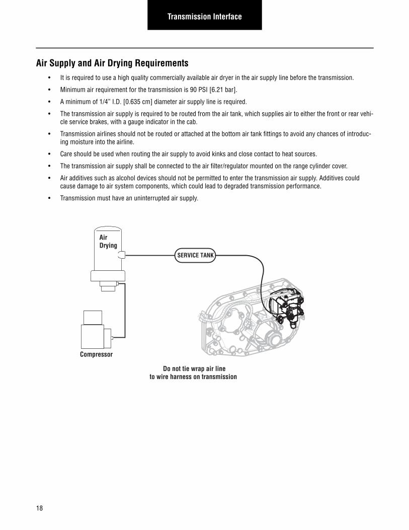
Air Supply and Air Drying Requirements• It is required to use a high quality commercially available air dryer in the air supply line before the transmission.
• Minimum air requirement for the transmission is 90 PSI [6.21 bar].
• A minimum of 1/4” I.D. [0.635 cm] diameter air supply line is required.
• The transmission air supply is required to be routed from the air tank, which supplies air to either the front or rear vehi-cle service brakes, with a gauge indicator in the cab.
• Transmission airlines should not be routed or attached at the bottom air tank fittings to avoid any chances of introduc-ing moisture into the airline.
• Care should be used when routing the air supply to avoid kinks and close contact to heat sources.
• The transmission air supply shall be connected to the air filter/regulator mounted on the range cylinder cover.
• Air additives such as alcohol devices should not be permitted to enter the transmission air supply. Additives could cause damage to air system components, which could lead to degraded transmission performance.
• Transmission must have an uninterrupted air supply.
SERVICE TANK
AirDrying
Compressor
Do not tie wrap air line to wire harness on transmission
19
Transmission InterfaceTransm
ission Interface
Lubrication Requirements and Specifications
Fuller Advantage Transmission Gear Box Lubrication Requirements
Eaton requires the use of a transmission lubricant that meets PS-164 rev 7 specification.
A list of approved lubricants and suppliers can be found in the Approved Lubricant Supplier Manual, TCMT0020.
Not using the required lubricant will result in degraded performance and shortened life of the product. Refer to the Lubrication Manual, TCMT0021, for the latest information regarding lubrication requirements.
Note: Eaton recommends the use of Eaton Roadranger Lubricants. Roadranger SAE 50 Synthetic Lubricant and Eaton PS-164 rev 7 are the only approved synthetic lubricants.
Note: Failure to adhere to Eaton installation requirements may affect the transmission performance and / or warranty coverage.
Warnings and Cautions
• Before working on a vehicle, place transmission in neutral, set brakes, and block wheels.
• Do not introduce additives and / or friction modifiers. Additives of any kind added later to the oil can result in unpredict-able consequences. No liability of any kind will be accepted by Eaton for any damage resulting from the use of such additives.
• Do not mix lubricants of different grades.
• Use clean containers when transferring lubricant from the bulk storage to the transmission. Containers used for anti-freeze or water should be cleaned prior to use.
• Do not re-use lubricant.
• Failure to use the required lubricant will affect the transmission performance and the warranty coverage.
• SAE 15W-40 viscosity grades are not allowed in Eaton transmissions.
Operating Temperatures and Cooling RequirementsThe Fuller Advantage transmission is designed to operate without a cooler for some applications. For cooler-less operation requirements refer to TRAG2600.
Required Lubricant
Transmission Gear Box - Eaton Roadranger SAE 50 Synthetic Lubricant or PS164 Rev 7 approved lubricant.
20
Transmission Interface
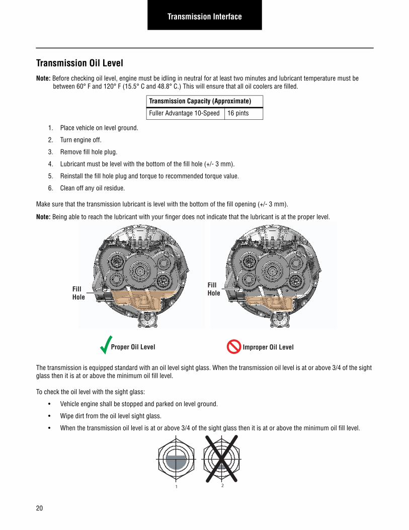
Transmission Oil LevelNote: Before checking oil level, engine must be idling in neutral for at least two minutes and lubricant temperature must be
between 60° F and 120° F (15.5° C and 48.8° C.) This will ensure that all oil coolers are filled.
1. Place vehicle on level ground.
2. Turn engine off.
3. Remove fill hole plug.
4. Lubricant must be level with the bottom of the fill hole (+/- 3 mm).
5. Reinstall the fill hole plug and torque to recommended torque value.
6. Clean off any oil residue.
Make sure that the transmission lubricant is level with the bottom of the fill opening (+/- 3 mm).
Note: Being able to reach the lubricant with your finger does not indicate that the lubricant is at the proper level.
The transmission is equipped standard with an oil level sight glass. When the transmission oil level is at or above 3/4 of the sight glass then it is at or above the minimum oil fill level.
To check the oil level with the sight glass:
• Vehicle engine shall be stopped and parked on level ground.
• Wipe dirt from the oil level sight glass.
• When the transmission oil level is at or above 3/4 of the sight glass then it is at or above the minimum oil fill level.
Transmission Capacity (Approximate)
Fuller Advantage 10-Speed 16 pints
Proper Oil Level Improper Oil Level
FillHole
FillHole
1 2
21
AppendixAppendix
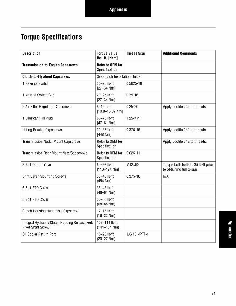
Torque Specifications
Description Torque Value lbs. ft. [N•m]
Thread Size Additional Comments
Transmission-to-Engine Capscrews Refer to OEM for Specification
Clutch-to-Flywheel Capscrews See Clutch Installation Guide
1 Reverse Switch 20–25 lb-ft [27–34 Nm]
0.5625-18
1 Neutral Switch/Cap 20–25 lb-ft [27–34 Nm]
0.75-16
2 Air Filter Regulator Capscrews 8–12 lb-ft [10.8–16.02 Nm]
0.25-20 Apply Loctite 242 to threads.
1 Lubricant Fill Plug 60–75 lb-ft [47–61 Nm]
1.25-NPT
Lifting Bracket Capscrews 30–35 lb-ft [448 Nm]
0.375-16 Apply Loctite 242 to threads.
Transmission Nodal Mount Capscrews Refer to OEM for Specification
Apply Loctite 242 to threads.
Transmission Rear Mount Nuts/Capscrews Refer to OEM for Specification
0.625-11
2 Bolt Output Yoke 84–92 lb-ft [113–124 Nm]
M12x60 Torque both bolts to 35 lb-ft prior to obtaining full torque.
Shift Lever Mounting Screws 30–40 lb-ft (454 Nm)
0.375-16 N/A
6 Bolt PTO Cover 35–45 lb-ft (48–61 Nm)
8 Bolt PTO Cover 50–65 lb-ft (68–88 Nm)
Clutch Housing Hand Hole Capscrew 12–16 lb-ft (16–22 Nm)
Integral Hydraulic Clutch Housing Release Fork Pivot Shaft Screw
106–114 lb-ft (144–154 Nm)
Oil Cooler Return Port 15–20 lb-ft (20–27 Nm)
3/8-18 NPTF-1
22
Appendix
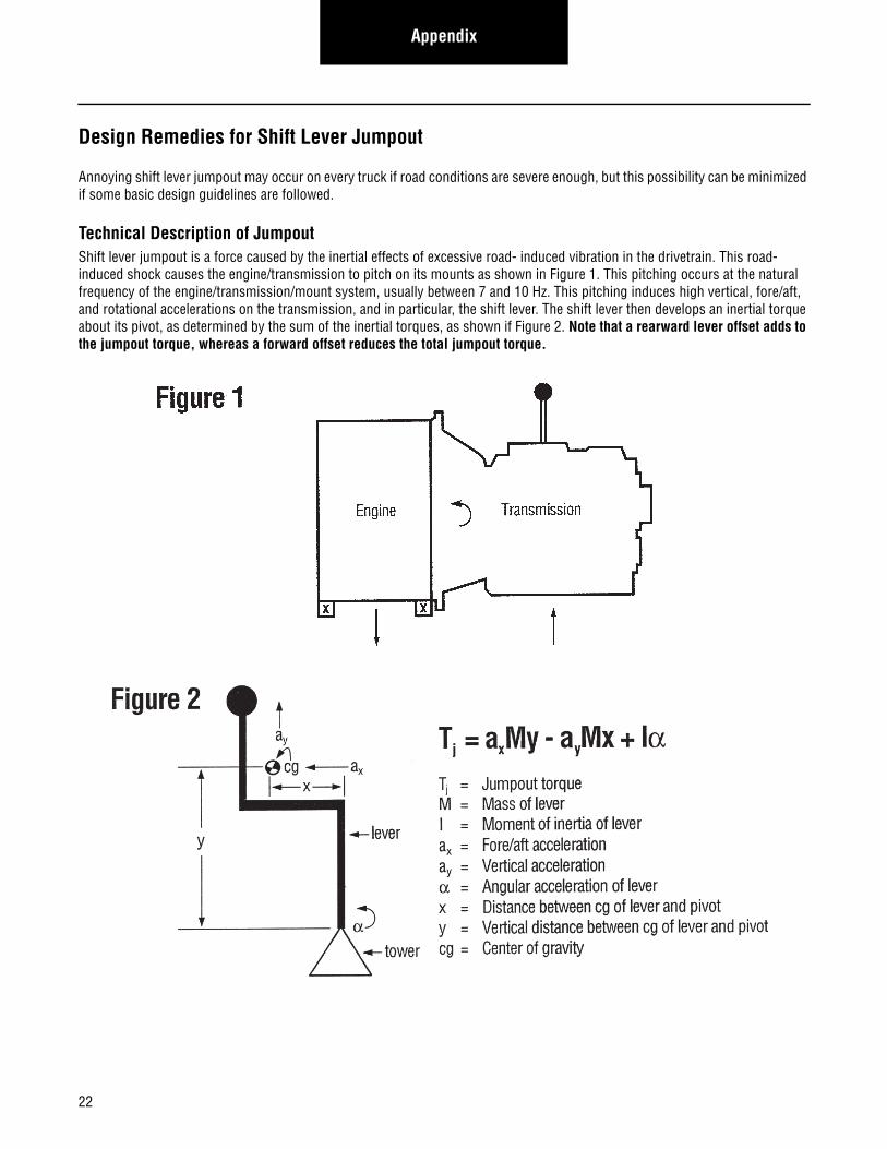
Design Remedies for Shift Lever Jumpout
Annoying shift lever jumpout may occur on every truck if road conditions are severe enough, but this possibility can be minimized if some basic design guidelines are followed.
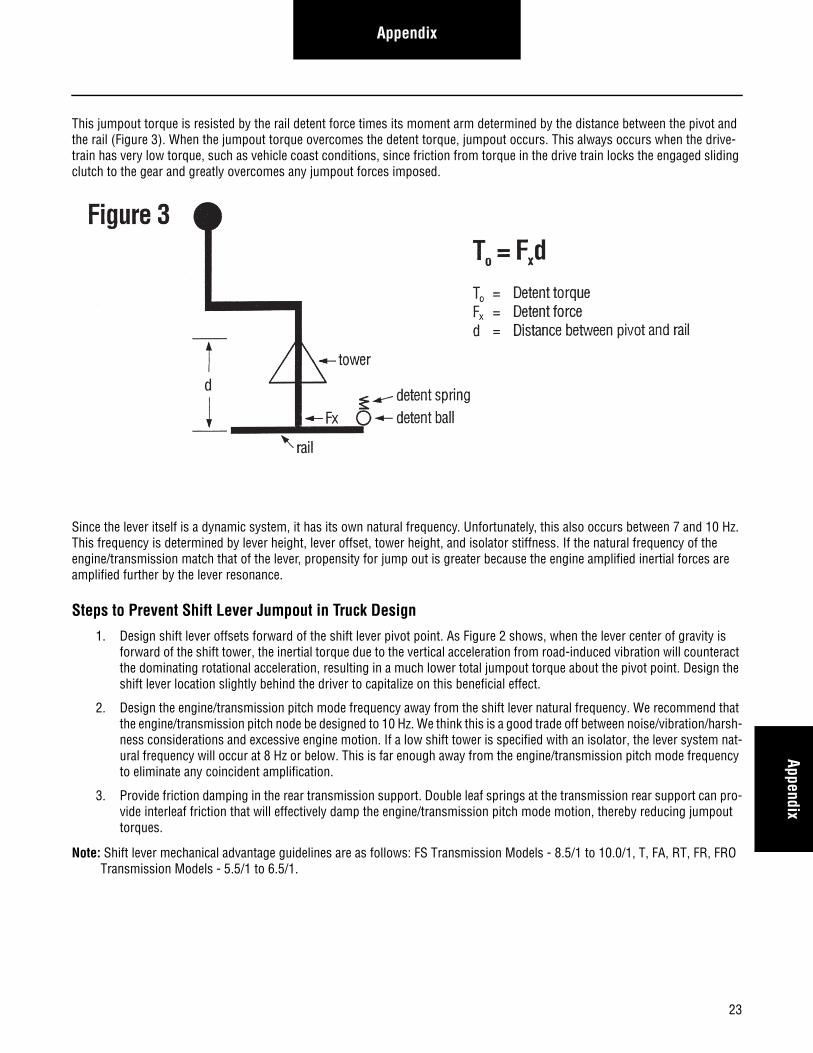
Technical Description of JumpoutShift lever jumpout is a force caused by the inertial effects of excessive road- induced vibration in the drivetrain. This road- induced shock causes the engine/transmission to pitch on its mounts as shown in Figure 1. This pitching occurs at the natural frequency of the engine/transmission/mount system, usually between 7 and 10 Hz. This pitching induces high vertical, fore/aft, and rotational accelerations on the transmission, and in particular, the shift lever. The shift lever then develops an inertial torque about its pivot, as determined by the sum of the inertial torques, as shown if Figure 2. Note that a rearward lever offset adds to the jumpout torque, whereas a forward offset reduces the total jumpout torque.
23
AppendixAppendix
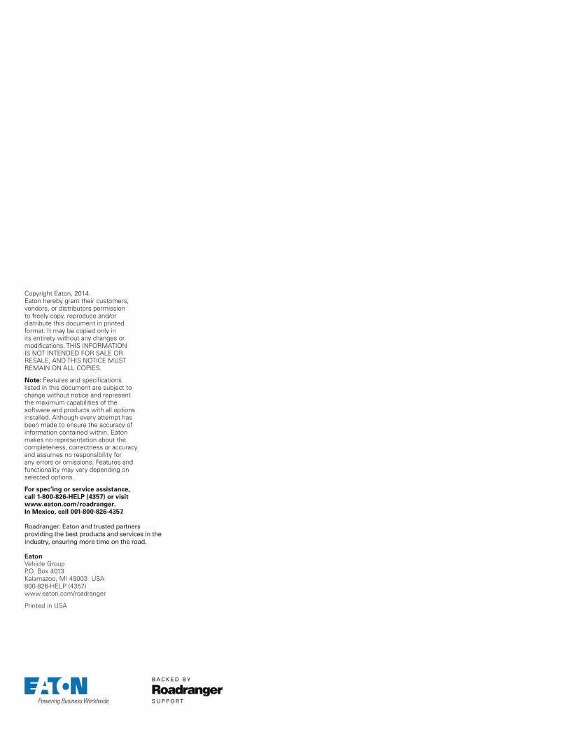
This jumpout torque is resisted by the rail detent force times its moment arm determined by the distance between the pivot and the rail (Figure 3). When the jumpout torque overcomes the detent torque, jumpout occurs. This always occurs when the drive-train has very low torque, such as vehicle coast conditions, since friction from torque in the drive train locks the engaged sliding clutch to the gear and greatly overcomes any jumpout forces imposed.
Since the lever itself is a dynamic system, it has its own natural frequency. Unfortunately, this also occurs between 7 and 10 Hz. This frequency is determined by lever height, lever offset, tower height, and isolator stiffness. If the natural frequency of the engine/transmission match that of the lever, propensity for jump out is greater because the engine amplified inertial forces are amplified further by the lever resonance.
Steps to Prevent Shift Lever Jumpout in Truck Design
1. Design shift lever offsets forward of the shift lever pivot point. As Figure 2 shows, when the lever center of gravity is forward of the shift tower, the inertial torque due to the vertical acceleration from road-induced vibration will counteract the dominating rotational acceleration, resulting in a much lower total jumpout torque about the pivot point. Design the shift lever location slightly behind the driver to capitalize on this beneficial effect.
2. Design the engine/transmission pitch mode frequency away from the shift lever natural frequency. We recommend that the engine/transmission pitch node be designed to 10 Hz. We think this is a good trade off between noise/vibration/harsh-ness considerations and excessive engine motion. If a low shift tower is specified with an isolator, the lever system nat-ural frequency will occur at 8 Hz or below. This is far enough away from the engine/transmission pitch mode frequency to eliminate any coincident amplification.
3. Provide friction damping in the rear transmission support. Double leaf springs at the transmission rear support can pro-vide interleaf friction that will effectively damp the engine/transmission pitch mode motion, thereby reducing jumpout torques.
Note: Shift lever mechanical advantage guidelines are as follows: FS Transmission Models - 8.5/1 to 10.0/1, T, FA, RT, FR, FRO Transmission Models - 5.5/1 to 6.5/1.

24
Change Control Log
Change Control Log
Last Revised Date Description of Clarifications and Updates
April 9, 2014 Added Oil Cooler Return Port Torque Specifications
May 14, 2013 Removed Low Oil Switch info throughout

25
Change Control LogChange Control
Log
Copyright Eaton, 2014. Eaton hereby grant their customers, vendors, or distributors permission to freely copy, reproduce and/or distribute this document in printed format. It may be copied only in its entirety without any changes or modifications. THIS INFORMATION IS NOT INTENDED FOR SALE OR RESALE, AND THIS NOTICE MUST REMAIN ON ALL COPIES.
Note: Features and specifications listed in this document are subject to change without notice and represent the maximum capabilities of the software and products with all options installed. Although every attempt has been made to ensure the accuracy of information contained within, Eaton makes no representation about the completeness, correctness or accuracy and assumes no responsibility for any errors or omissions. Features and functionality may vary depending on selected options.
For spec’ing or service assistance, call 1-800-826-HELP (4357) or visit www.eaton.com/roadranger.In Mexico, call 001-800-826-4357.
EatonVehicle GroupP.O. Box 4013Kalamazoo, MI 49003 USA800-826-HELP (4357)www.eaton.com/roadranger
Printed in USA
Roadranger: Eaton and trusted partners providing the best products and services in the industry, ensuring more time on the road.