Embed Size (px)
Citation preview

FULL-SCALE REELING TESTS OF HFI WELDED LINE PIPE FOR OFFSHORE
REEL-LAYING INSTALLATION
Karl Christoph Meiwes Salzgitter Mannesmann Forschung GmbH
Duisburg, Germany
Susanne Höhler Salzgitter Mannesmann Forschung GmbH
Duisburg, Germany
Marion Erdelen -Peppler Salzgitter Mannesmann Forschung GmbH
Duisburg, Germany
Holger Brauer Salzgitter Mannesmann Line Pipe GmbH
Hamm, Germany
ABSTRACT During reel-laying repeated plastic strains are introduced into a pipeline which may affect strength properties and deformation capacity of the line pipe material. Conventionally the effect on the material is simulated by small-scale reeling simulation tests. For these, coupons are extracted from pipes that are loaded in tension and compression and thermally aged, if required. Afterwards, specimens for mechanical testing are machined from these coupons and tested according to the corresponding standards. Today customers often demand additional full-scale reeling simulation tests to assure that the structural pipe behavior meets the strain demands as well. Realistic deformations have to be introduced into a full-size pipe, followed by aging, sampling and mechanical testing comparable to small-scale reeling. In this report the fitness for use of a four-point-bending test rig for full-scale reeling simulation tests is demonstrated. Two high-frequency-induction (HFI) welded pipes of grade X65M (OD = 323.9 mm, WT = 15.9 mm) from Salzgitter Mannes-mann Line Pipe GmbH (MLP) are bent with alternate loading. To investigate the influences of thermal aging from polymer-coating process one test pipe had been heat treated beforehand, in the same manner as if being PE-coated. After the tests mechanical test samples were machined out of the plastically strained pipes. A comparison of results from mechanical testing of material exposed to small- and full-scale reeling simulation is given. The results allow an evaluation of the pipe behavior as regards reeling ability and plastic deformation capacity.
INTRODUCTION Reel-laying is a fast and cost effective method to install offshore pipelines for deep subsea application (Figure 1). The time and cost-intensive operations of welding and inspection are carried out onshore. The welded pipeline is reeled onto a drum before being transported to the installation site offshore by a reel-laying barge which can then conduct the laying operation at a comparably high speed. The amount of strain the pipes are subjected to depends on the characteristics of the reel-laying barge, and here most importantly on the radius of the reel drum. The first layer of pipes in contact to the drum is deformed to the drum radius whereas each subsequent layer has a radius that, in comparison to the layer before, is increased by the pipe diameter. Generally speaking, reel-laying consists of four load steps which are essentially strain or displacement controlled bending operations: reeling onto the drum onshore, reeling off the drum offshore, straightening and aligning and overbending in the straightener to account for any springback inferring with the straightness of the pipe string.
Proceedings of the 2014 10th International Pipeline Conference IPC2014
September 29 - October 3, 2014, Calgary, Alberta, Canada
IPC2014-33163
1 Copyright © 2014 by ASME
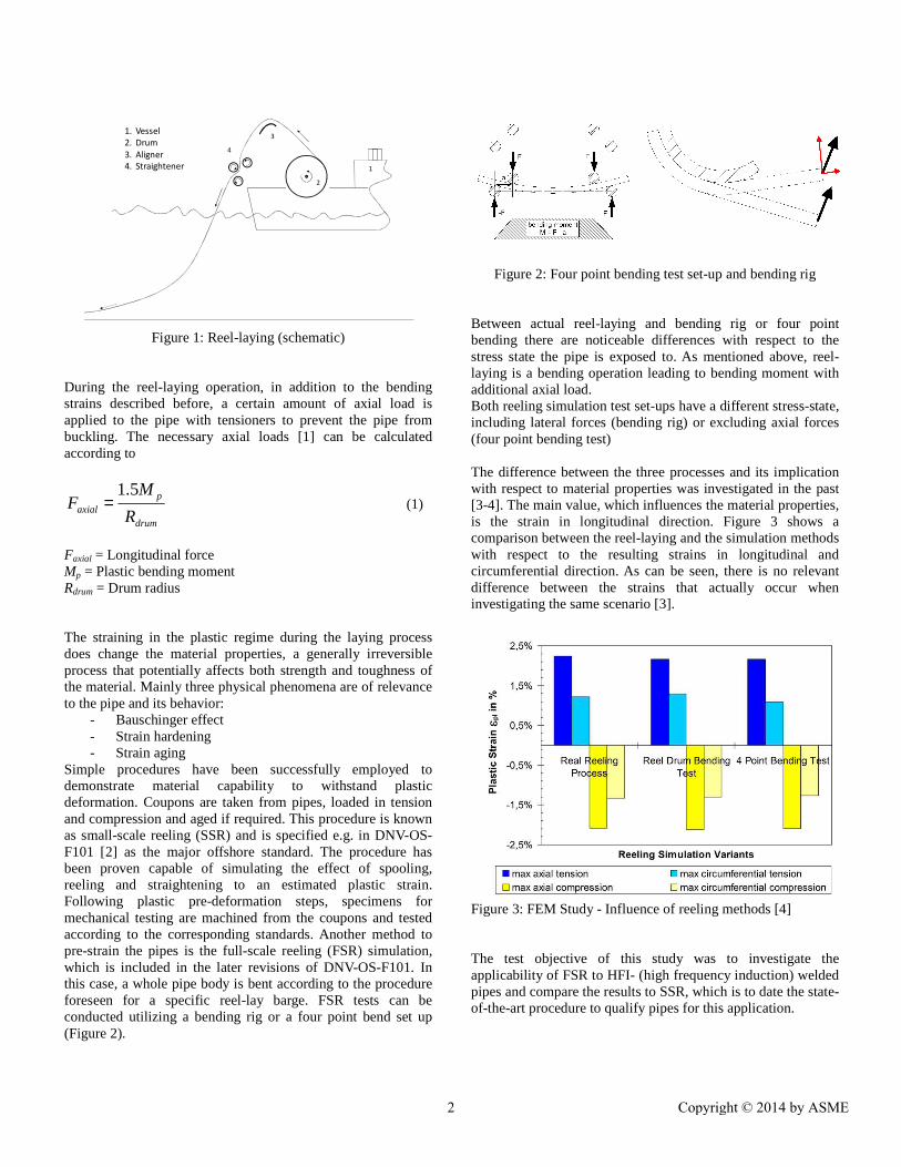
Figure 1: Reel-laying (schematic) During the reel-laying operation, in addition to the bending strains described before, a certain amount of axial load is applied to the pipe with tensioners to prevent the pipe from buckling. The necessary axial loads [1] can be calculated according to
drum
paxial R
MF
5.1= (1)
Faxial = Longitudinal force Mp = Plastic bending moment Rdrum = Drum radius The straining in the plastic regime during the laying process does change the material properties, a generally irreversible process that potentially affects both strength and toughness of the material. Mainly three physical phenomena are of relevance to the pipe and its behavior:
- Bauschinger effect - Strain hardening - Strain aging
Simple procedures have been successfully employed to demonstrate material capability to withstand plastic deformation. Coupons are taken from pipes, loaded in tension and compression and aged if required. This procedure is known as small-scale reeling (SSR) and is specified e.g. in DNV-OS-F101 [2] as the major offshore standard. The procedure has been proven capable of simulating the effect of spooling, reeling and straightening to an estimated plastic strain. Following plastic pre-deformation steps, specimens for mechanical testing are machined from the coupons and tested according to the corresponding standards. Another method to pre-strain the pipes is the full-scale reeling (FSR) simulation, which is included in the later revisions of DNV-OS-F101. In this case, a whole pipe body is bent according to the procedure foreseen for a specific reel-lay barge. FSR tests can be conducted utilizing a bending rig or a four point bend set up (Figure 2).
Figure 2: Four point bending test set-up and bending rig Between actual reel-laying and bending rig or four point bending there are noticeable differences with respect to the stress state the pipe is exposed to. As mentioned above, reel-laying is a bending operation leading to bending moment with additional axial load. Both reeling simulation test set-ups have a different stress-state, including lateral forces (bending rig) or excluding axial forces (four point bending test)
The difference between the three processes and its implication with respect to material properties was investigated in the past [3-4]. The main value, which influences the material properties, is the strain in longitudinal direction. Figure 3 shows a comparison between the reel-laying and the simulation methods with respect to the resulting strains in longitudinal and circumferential direction. As can be seen, there is no relevant difference between the strains that actually occur when investigating the same scenario [3].
Figure 3: FEM Study - Influence of reeling methods [4] The test objective of this study was to investigate the applicability of FSR to HFI- (high frequency induction) welded pipes and compare the results to SSR, which is to date the state-of-the-art procedure to qualify pipes for this application.
1
2
3
4
1. Vessel
2. Drum
3. Aligner
4. Straightener
2 Copyright © 2014 by ASME

FULL-SCALE REELING SIMULATION Full-scale test device The test rig located at Salzgitter Mannesmann Forschung GmbH (SZMF) in Duisburg, Germany, is a fourdevice. The installation of such bending test facility was motivated by several pipe and pipeline applications.of strain-based design plays a major role, where axial strains must be considered in the pipeline from curvatures or bending forces due to ground movements, Next, a bending test allows for simulating pipeline laying activities, such as reelcold bending of pipes, and supports research activities related to residual load bearing and straining capacities of pipes.The test rig is a vertical four-point-bending devicewith four hydraulic jacks with each 2,500 kN (twoone load application point, respectively). Thus, a total load capacity of 10,000 kN (1,000 tons) is availableare supported by a welded steel frame. An overview of the test rig is sketched in Figure 4.
Figure 4: Full-scale bending test rig at SZMF
Maximum width between outer bearings diameters may reach up to 56” and typical pipe may go up to API 5L [5] X100 can be testedjacks allow for a maximum stroke of 1,100outer bearings is undisplaceably fixed to the steel frame while the other bearing and the two loading planes can be moved along the pipe axis (Figure 5). Thus, the distance between the supports can be chosen according to the pipe dimensions and test requirements.designed such that longitudinal forces are negligibletesting rig has slewing bearings (radial variance) the axial force during bending.
Figure 5: Schematic of four-point bending test at SZMF
The test rig located at Salzgitter Mannesmann Forschung GmbH (SZMF) in Duisburg, Germany, is a four-point-bending
The installation of such bending test facility was motivated by several pipe and pipeline applications. The field
esign plays a major role, where axial strains must be considered in the pipeline from curvatures or bending
Next, a bending test allows for simulating pipeline laying activities, such as reel-laying or
and supports research activities related to residual load bearing and straining capacities of pipes.
bending device equipped kN (two jacks act on
espectively). Thus, a total load is available. The bearings
are supported by a welded steel frame. An overview of the test
scale bending test rig at SZMF
is about 15.5 m; typical pipe steel grades
can be tested. The hydraulic 100 mm. One of the
outer bearings is undisplaceably fixed to the steel frame while the other bearing and the two loading planes can be flexibly
. Thus, the pipe length and the distance between the supports can be chosen according to the pipe dimensions and test requirements. The test set-up is designed such that longitudinal forces are negligible, as the testing rig has slewing bearings (radial variance) to compensate
point bending test at SZMF
For reeling tests alternate bending loading can be applied.hydraulic jacks are able to act both in compression (upwards) and tension (downwards) direction Test pipes for full-scale reelingTwo reeling simulations have been performed on HFIpipes produced by Salzgitter MannAPI X65M steel grade and order to include any thermal aging effects from the polymercoating process, where the pipe temperature can reach 200to 250 °C for several minutes, one of the two test pipeundergone a heat treatment as if being provided with polyethylene (PE)-coating. In fact the test pipe was heated for 5 minutes with the temperature of realistic application of a polysimulated. Both pipes had a length of 6.0the pipes are referred to as Pipe 1 – AR (“as rolled Pipe 2 – PE (“PE-coated”) The test pipes were installed in the test rig such that the HFI weld was located in the neutral bending axismaterial of the pipe. The pipegauges in longitudinal direction(planes A - E) within the test section(extrados) and 6 o’clock positionFigure 6 and Figure 7. The alternate bending operationsdisplacement controlled condition.values were continuously recorded. Furthermore, force and displacement of the hydraulic jacks were measured throughout the tests. In order to realistically simulate the reeling process four test steps were carried out where thewere envisaged: 1. Bending to plastic strain of 22. Reverse bending to plastic 3. Bending to plastic strain of 24. Reverse bending to plastic
For reeling tests alternate bending loading can be applied. The hydraulic jacks are able to act both in compression (upwards)
direction to realize reverse bending.
eeling have been performed on HFI welded
pipes produced by Salzgitter Mannesmann Line Pipe GmbH in steel grade and 323.9 mm OD x 15.9 mm WT. In
order to include any thermal aging effects from the polymer-coating process, where the pipe temperature can reach 200 °C
°C for several minutes, one of the two test pipes had undergone a heat treatment as if being provided with poly-
coating. In fact the test pipe was heated for minutes with the temperature of around 210 °C. Thus, a
realistic application of a poly-ethylene (PE)-coated pipe was h pipes had a length of 6.0 m. In the following
as rolled”) coated”)
installed in the test rig such that the HFI weld was located in the neutral bending axis to analyse the base
. The pipes were instrumented with strain in longitudinal direction in five measuring planes
) within the test section in the 12 o’clock o’clock position (intrados) of the pipes, see
operations were carried out in displacement controlled condition. During the tests the strain values were continuously recorded. Furthermore, force and displacement of the hydraulic jacks were measured throughout the tests. In order to realistically simulate the reeling process four test steps were carried out where the following strain limits
Bending to plastic strain of 2 % - reeling on (+2 %) plastic strain of 0 % - reeling off (-2 %)
Bending to plastic strain of 2 % - aligning (+2 %) plastic strain of 0 % (-2 %)
3 Copyright © 2014 by ASME
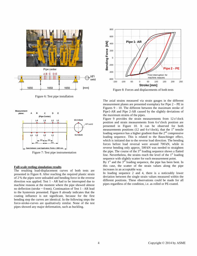
Figure 6: Test pipe installation
Figure 7: Test pipe instrumentation
Full-scale reeling simulation results The resulting load-displacement curves of both tests are presented in Figure 8. After reaching the required plastic strain of 2 % the pipes were unloaded and bending force in the reverse direction was applied. Test 1 - AR had to be interrupted due to machine reasons at the moment where the pipe showed almost no deflection (stroke ~ 0 mm). Continuation of Test 1 - AR lead to the hysteresis presented. Figure 8 already indicates that the coating influence is not significant, because for the first bending step the curves are identical. In the following steps the force-stroke-curves are qualitatively similar. None of the test pipes showed any major deformation, such as buckling.
Figure 8: Forces and displacements of both tests
The axial strains measured via strain gauges in the different measurement planes are presented exemplary for Pipe 2 – PE in Figures 9 - 10. The different between the maximum stroke of Pipe1-AR and Pipe 2-AR caused by the slightly deviations of the maximum strains of the pipes. Figure 9 provides the strain measurements from 12 o’clock position and strain measurements from 6 o’clock position are presented in Figure 10. It can be observed for both measurements positions (12 and 6 o’clock), that the 1st tensile loading sequence has a higher gradient than the 2nd compressive loading sequence. This is related to the Bauschinger effect, which is initiated due to the reverse load direction. The bending forces before load reversal were around 700 kN, while in reverse bending only approx. 500 kN was needed to straighten the pipe. The course of the 3rd loading sequence shows a flatted line. Nevertheless, the strains reach the level of the 1st loading sequence with slightly scatter for each measurement point. By 1st and the 3rd loading sequence, the pipe has been bent. In this case, the scatter of the strain values along the pipe increases in an acceptable way. In loading sequence 2 and 4, there is a noticeably lower deviation between the single strain values measured within the different positions. These observations could be made for all pipes regardless of the condition, i.e. as rolled or PE-coated.
350350
500500
Span between Load Application Points = 1650 mm
12 o‘clock
6 o‘clock
HFI-weld
Measurementplane: EDA CB
L1
L2
L3
L4 L1
L2
L3
L4
(Pipe-Center)
-600
-400
-200
0
200
400
600
800
-150 -100 -50 0 50 100 150 200 250
Ben
ding
For
ce [
kN]
Stroke [mm]
Pipe 2 - PE
Pipe 1- AR
Test interruption formachine reasons
4 Copyright © 2014 by ASME

Figure 9: Strain measurements in 12 o’clock, Pipe 2-PE
Figure 10: Strain measurements in 6 o’clock, Pipe 2-PE
Generally, no major differences between the test results of the two pipes and thus, between the two heating conditions (“AR” versus “PE”) are observed. After FSR Simulation, segments were removed from the pipe (12 and 6 o’clock position) and exposed to 250 °C for one hour as specified in DNV-OS-F101 for simulation of an aging effect during pipe service. Subsequently, the specimens needed for mechanical testing were machined.
Results of mechanical testing and discussion In the following, the results of experimental tests after FSR simulation are compared with results after SSR simulation, for details see IPC2014-33161 [6]. This is done with both specimens extracted in the 12 o’clock and 6 o’clock positions and, in the case of SSR, specimens exposed to compression-tension (comparable to 6 o’clock) and tension-compression (comparable to 12 o’clock) cycles, respectively. Thereby, a complete picture of the material response to straining cycles as they occur in a reeling operation is given. Tensile properties Tensile tests were conducted on round bar specimens extracted in longitudinal direction according to DIN EN ISO 6892-1 [7] at ambient temperature. Figure 11 shows the results of tensile tests of reeled and aged specimens of Pipe 1-AR, as rolled, and Pipe 2-PE, thermally aged. As-delivered constitutes the tensile results before reeling simulation and thermal aging. After reeling simulation and aging the tensile properties were tested in pairs, i.e. for each pipe condition two tensile test results are available. It is obvious that the direction of the last cycle has a major influence on the yield strength of the material. In this case, yield strength was determined in terms of Rt0.5, that is defined as yield strength at 0.5 % total elongation. In 12 o’clock normal cycling, which ends in compression, the Yield strength (YS) is noticeably lower (in the order of 100 MPa) than after straining in the opposite order of cycles (6 o’clock position). This is due to the Bauschinger effect that leads to a decrease in yield strength after plastic deformation in the opposite direction. The initial Yield strength of Pipe 1-AR and Pipe 2-PE ranges between the values after straining and aging. The reason for this is strain aging of the material. In contrast to this, the ultimate tensile strength remains unaffected by the straining procedure and the properties are in a small scatter-band of around 20 MPa for all conditions.
Figure 11: Tensile properties
Concerning a possible influence of the procedure used to apply the strain, i.e. FSR or SSR, there is no noticeable influence
-600
-400
-200
0
200
400
600
800
-1 -0.5 0 0.5 1 1.5 2 2.5 3
Be
ndin
g fo
rce
, kN
Axial strains 12 o'clock position, %
B
C
D
E
-600
-400
-200
0
200
400
600
800
-3.0 -2.5 -2.0 -1.5 -1.0 -0.5 0.0 0.5 1.0
Ben
ding
forc
e, k
N
Axial strains 6 o'clock position, %
A
B
C
D
450
500
550
600
650
450 500 550 600 650
Tens
ile p
rope
rtie
s -S
SR
, MP
a
Tensile properties - FSR, MPa
Pipe 1-AR: as-deliveredPipe 2-PE: as-deliveredPipe 1-AR: straining+agingPipe 2-PE : straining+aging
UTS
YS
Solid: normal / 12 o'clock position
Open: reversed / 6 o'clock position
1st cycle
2nd cycle
1st cycle
2nd cycle
Failure of strain gauge
Failure of strain gauge
5 Copyright © 2014 by ASME
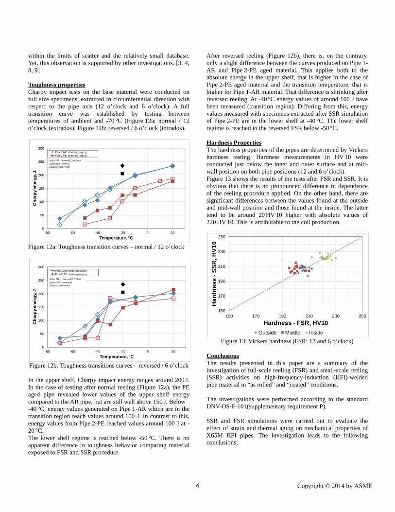
within the limits of scatter and the relatively small database. Yet, this observation is supported by other investigations. [3, 4, 8, 9] Toughness properties Charpy impact tests on the base material were conducted on full size specimens, extracted in circumferential direction with respect to the pipe axis (12 o’clock and 6 o’clock). A full transition curve was established by testing between temperatures of ambient and -70 °C (Figure 12a: normal / 12 o’clock (extrados); Figure 12b: reversed / 6 o’clock (intrados).
Figure 12a: Toughness transition curves – normal / 12 o’clock
Figure 12b: Toughness transitions curves – reversed / 6 o’clock In the upper shelf, Charpy impact energy ranges around 200 J. In the case of testing after normal reeling (Figure 12a), the PE aged pipe revealed lower values of the upper shelf energy compared to the AR pipe, but are still well above 150 J. Below -40 °C, energy values generated on Pipe 1-AR which are in the transition region reach values around 100 J. In contrast to this, energy values from Pipe 2-PE reached values around 100 J at -20 °C. The lower shelf regime is reached below -50 °C. There is no apparent difference in toughness behavior comparing material exposed to FSR and SSR procedure.
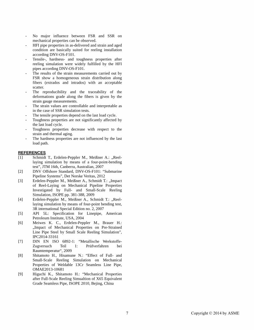
After reversed reeling (Figure 12b), there is, on the contrary, only a slight difference between the curves produced on Pipe 1-AR and Pipe 2-PE aged material. This applies both to the absolute energy in the upper shelf, that is higher in the case of Pipe 2-PE aged material and the transition temperature, that is higher for Pipe 1-AR material. That difference is shrinking after reversed reeling. At -40 °C energy values of around 100 J have been measured (transition region). Differing from this, energy values measured with specimens extracted after SSR simulation of Pipe 2-PE are in the lower shelf at -40 °C. The lower shelf regime is reached in the reversed FSR below -50 °C. Hardness Properties The hardness properties of the pipes are determined by Vickers hardness testing. Hardness measurements in HV 10 were conducted just below the inner and outer surface and at mid-wall position on both pipe positions (12 and 6 o’clock). Figure 13 shows the results of the tests after FSR and SSR. It is obvious that there is no pronounced difference in dependence of the reeling procedure applied. On the other hand, there are significant differences between the values found at the outside and mid-wall position and those found at the inside. The latter tend to be around 20 HV 10 higher with absolute values of 220 HV 10. This is attributable to the coil production.
Figure 13: Vickers hardness (FSR: 12 and 6 o’clock)
Conclusions The results presented in this paper are a summary of the investigation of full-scale reeling (FSR) and small-scale reeling (SSR) activities on high-frequency-induction (HFI)-welded pipe material in “as rolled” and “coated” conditions. The investigations were performed according to the standard DNV-OS-F-101(supplementary requirement P). SSR and FSR simulations were carried out to evaluate the effect of strain and thermal aging on mechanical properties of X65M HFI pipes. The investigation leads to the following conclusions:
0
50
100
150
200
250
300
-80 -60 -40 -20 0 20
Cha
rpy
ener
gy, J
Temperature, °C
Pipe 1 AR: straining+agingPipe 2 PE: straining+aging
Solid: FSR - normal/12 o'clock
Open: SSR - normal
Black: as-delivered
0
50
100
150
200
250
300
-80 -60 -40 -20 0 20
Cha
rpy
ener
gy, J
Temperature, °C
Pipe 1 AR: straining+agingPipe 2 PE: straining+aging
Solid: FSR - reversed/6 o'clock
Open: SSR - reversed
Black: as-delivered
150
170
190
210
230
250
150 170 190 210 230 250
Har
dnes
s -
SS
R, H
V10
Hardness - FSR, HV10
Outside Middle Inside
6 Copyright © 2014 by ASME
- No major influence between FSR and SSR on mechanical properties can be observed.
- HFI pipe properties in as-delivered and strain and aged condition are basically suited for reeling installation according DNV-OS-F101.
- Tensile-, hardness- and toughness properties after reeling simulation were widely fulfilled by the HFI pipes according DNV-OS-F101.
- The results of the strain measurements carried out by FSR show a homogeneous strain distribution along fibers (extrados and intrados) with an acceptable scatter.
- The reproducibility and the traceability of the deformations grade along the fibers is given by the strain gauge measurements.
- The strain values are controllable and interpretable as in the case of SSR simulation tests.
- The tensile properties depend on the last load cycle. - Toughness properties are not significantly affected by
the last load cycle. - Toughness properties decrease with respect to the
strain and thermal aging. - The hardness properties are not influenced by the last
load path.
REFERENCES [1] Schmidt T., Erdelen-Peppler M., Meißner A.: „Reel-
laying simulation by means of a four-point-bending test”, JTM 16th, Canberra, Australian, 2007
[2] DNV Offshore Standard, DNV-OS-F101: “Submarine Pipeline Systems”, Det Norske Veritas, 2012
[3] Erdelen-Peppler M., Meißner A., Schmidt T.: „Impact of Reel-Laying on Mechanical Pipeline Properties Investigated by Full- and Small-Scale Reeling Simulation, ISOPE pp. 381-388, 2009
[4] Erdelen-Peppler M., Meißner A., Schmidt T.: „Reel-laying simulation by means of four-point bending test, 3R international Special Edition no. 2, 2007
[5] API 5L: Specification for Linepipe, American Petroleum Institute, USA, 2004
[6] Meiwes K. C., Erdelen-Peppler M., Brauer H.: „Impact of Mechanical Properties on Pre-Strained Line Pipe Steel by Small Scale Reeling Simulation”, IPC2014-33161
[7] DIN EN ISO 6892-1: “Metallische Werkstoffe-Zugversuch Teil 1: Prüfverfahren bei Raumtemperatur“, 2009
[8] Shitamoto H., Hisamune N.: “Effect of Full- and Small-Scale Reeling Simulation on Mechanical Properties of Weldable 13Cr Seamless Line Pipe, OMAE2013-10681
[9] Higuchi K., Shitamoto H.: “Mechanical Properties after Full-Scale Reeling Simualtion of X65 Equivalent Grade Seamless Pipe, ISOPE 2010, Bejing, China
7 Copyright © 2014 by ASME