Embed Size (px)
Citation preview

The BOUSSOLE project technical reports
Full rotation of the BOUSSOLE buoy and mooring
September 15-18, 2019
Picture of the “Castor 02” vessel soon before the deployment of the buoy upper superstructure.
V. VELLUCCI
Institut de la Mer de Villefranche (IMEV),
06230 Villefranche-sur-Mer, FRANCE
BOUSSOLE Project
September 30, 2019

Foreword
This report is part of the technical report series that is being established by the BOUSSOLE project.
BOUSSOLE is funded/supported by the following Agencies, Institutions or Programs
European Space Agency
Centre National d’Etudes Spatiales, France
Centre National de la Recherche Scientifique, France
Institut National des Sciences de l’Univers, France
Sorbonne Université, France
Institut de la Mer de Villefranche, France

1
Table of contents
CRUISE OBJECTIVES, MOTIVATION FOR THE BUOY AND MOORING ROTATION ...................... 2
PRELIMINARY ORGANIZATION BEFORE LAUNCHING THE DEPLOYMENT OPERATIONS ...... 2
1.1 LOWER SUPERSTRUCTURE VERIFICATION AND PREPARATION ................................................................. 2 1.2 MOORING LINE, IN PARTICULAR THE KEVLAR CABLE ............................................................................. 3 1.3 WEATHER FORECAST .............................................................................................................................. 3 1.4 GENERAL MANAGEMENT ISSUES ............................................................................................................ 5 1.5 COMMUNICATION EQUIPMENT (SATELLITE PHONE) ................................................................................ 5
CRUISE SUMMARY ........................................................................................................................................... 6
DETAILED CRUISE REPORT .......................................................................................................................... 6
DIFFICULTIES ENCOUNTERED DURING, AND LESSONS LEARNED FROM, THIS
DEPLOYMENT .................................................................................................................................................... 9
APPENDIX 1: SCHEMES OF THE MOORING LINE ................................................................................. 10
APPENDIX 2: TOP OF THE TEMPORARY MOORING LINE .................................................................. 12
APPENDIX 3: PICTURES OF THE BUOY DEPLOYMENT ....................................................................... 13
APPENDIX 4. SPECIFICATION FOR THE KEVLAR CABLE ................................................................. 19
APPENDIX 5. REPORT OF THE KEVLAR CABLE CONSTRUCTION .................................................. 21
APPENDIX 6: MAGNETIC PARTICLE INSPECTION REPORT .............................................................. 24
APPENDIX 7: ULTRASONIC TESTING REPORT ...................................................................................... 33
APPENDIX 8: NOMINAL (THEORETICAL) LIST OF OPERATIONS FOR THE DEPLOYMENT .... 37
APPENDIX 9: CONTACTS ............................................................................................................................... 38

2
Cruise objectives, motivation for the buoy and mooring rotation
The objective of the cruise reported here was to recover the BOUSSOLE mooring line and buoy lower superstructure (see App. 2 for a schematic view), and to reinstall a new mooring line and buoy lower superstructure. The buoy upper superstructure has been temporarily dismounted from the recovered lower superstructure and then mounted onto the new lower superstructure.
The last similar operation took place on 26th to 29th August of 2016. This means the mooring line and the lower superstructure have stayed at sea about 37 months. No particular issues on the Kevlar cable and terminations were noticed after they were retrieved except damage due to fishermen activities (see Pic. 11). The lower superstructure did not suffer biofouling however the condition of the paint was not good at visual inspection showing seawater infiltration in many points and rust formation (see Pic. 43-46).
These operations are necessary as far as the longevity of the Kevlar mooring cable and of the lower superstructure (the main buoyancy) are still not totally know; moreover, the acoustic release battery lifetime is of approximately 5 years, whereas their anodes are exhausted after 3 years.
The excellent physical status of all mooring line elements confirms that a rotation every 3 years can be safely maintained in the future, however verification of the lower superstructure and its partial reconditioning (i.e. sandblasting, primary and secondary paint) is recommended within few weeks from the recovery for proper storage and preventing further corrosion.
The FOSELEV MARINE Company had a long closure in summertime (the full month of August) and the first planned available day was September 2nd. Mobilization of the CASTOR 02 eventually started on September 14th and the start of operations at sea was on August 15th (see the detailed cruise report below).
Preliminary organization before launching the deployment operations
1.1 Lower superstructure verification and preparation
After the mooring recovery of August 2016, the lower superstructure has been stored at the premises of the FOSELEV MARINE company in La Seyne-sur-Mer. The preparation of the lower superstructure took place there under the supervision of Léo Jimenez. The preparation started in July 2019 and lasted about 1 month.
The scheduled interventions on the structure were: sandblast of the old paint, verification of the integrity of welds and of the thickness of metal sheets, painting, and installation of new anodes.
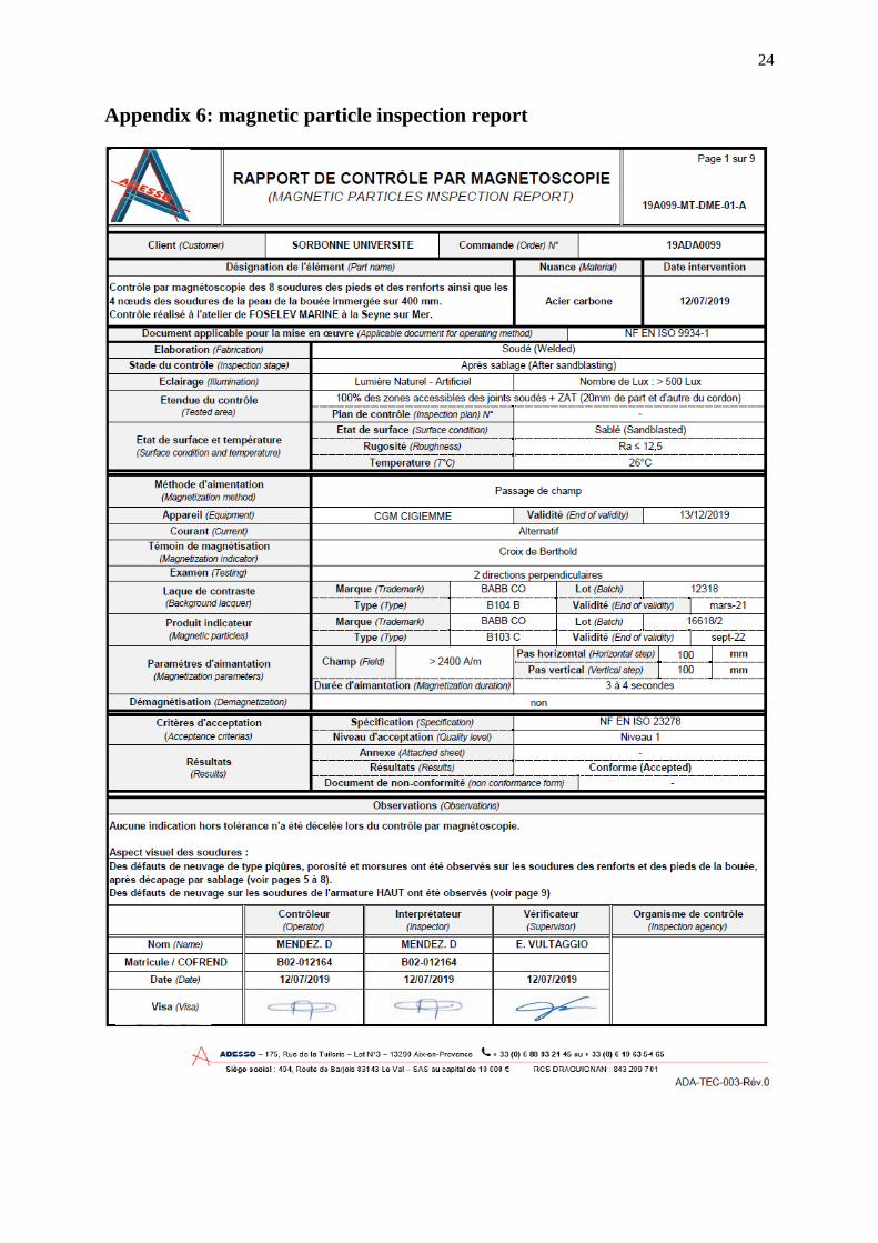
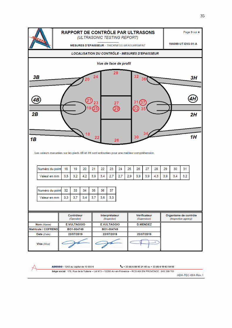
The magnetic and ultrasonic verifications were performed by the ADESSO Company. Some defects were found on few weld joints of tubular structural elements. These defects were already present on the original structure and did not require a specific intervention. Reports of this verification are reported in App. 6 and 7.
The painting was applied as successive layers of1: 1 layer of Primer Intergrad 269, 3 layers of Interzone 954, 2 layers of Intergard 263, 2 layers of Trilux 33. It is recommended to apply the last antifouling layer (Trilux 33) not earlier than 1 month before the deployment to guarantee its effectiveness. Protecting the structure from sun exposition also helps keeping the effectiveness of the antifouling (this precaution was however not taken).
1 These references are those from the paint company “International”

3
Another crucial point is to have the anodes directly connected to the metal of the structure. The connection plate (i.e., the plate connecting the lower superstructure to the mast) was painted in yellow to ameliorate its visibility from surface after its deployment.
This structure was ready by the end of July. Plastic washers were already fixed since the previous deployment with epoxy glue
(“Araldite” brand) on the buoy plate to avoid contact between stainless steel bolts and the buoy, which is made of simple steel.
1.2 Mooring line, in particular the Kevlar cable
A critical and preliminary step consists in determining the length of the Kevlar cable and its elongation under a strain of about 2.7 tons, which corresponds to the net buoyancy of the entire buoy and mooring line.
The principle is first to weigh a sample of cable of a precisely known length (minimum of 20 meters) with a high-precision scale, and then to adjust the length of the full mooring cable as a function of its total weight. This procedure proved to be robust, and is mandatory because the length meter used during the production of the cable is not accurate enough to give the requested precision of a few meters. The cable length must be computed so that it is at the desired value when under tension. The coefficient of elongation is estimated using a sample of the cable under production and the appropriate test bed for tension measurements. The cable manufacturer, Lapp Muller, performs all these operations and delivers a certificate describing these operations and the numerical values for the different weightings and elongation measurements (App. 1).
The purchase order for the cable was placed at the beginning of March 2019 and the cable was delivered to FOSELEV MARINE at the end of May.
The acoustic releases were shipped to Ixblue in Brest for general verification at the beginning of April. O rings, anodes and lithium batteries were replaced by new ones. The gears were then delivered to FOSELEV MARIN two months later.
1.3 Weather forecast
The recovery, and above all the deployment, of the BOUSSOLE mooring and buoy requires a perfectly calm weather and, ideally, no current. It is, therefore, mandatory not to start the operations with anticipated wind speeds above 10 knots. Forecasts below 5 knots for at least 2 days are the ideal situation. It is not recommended to start operations just after strong winds have blown, because the wind-generated surface currents usually take several days to attenuate.
Several weather forecast systems have been used in the preparation of the operations, in order to increase the confidence in the weather forecast as compared to what would be obtained using a unique source. They are:
The long-term forecast of the ECMWF (pressure fields), at: http://www.ecmwf.int/products/forecasts/d/charts/medium/deterministic/msl_uv850_z
500 Wind field forecasts of: https://www.windy.com/ http://www.weatheronline.co.uk/cgi-bin/windkarten?03&LANG=en&WIND=g030 https://www.meteoblue.com/en/weather/forecast/week/villefranche-sur-
mer_france_6425698

4
http://www.meteociel.com/modeles/gfs/resume/3h.htm http://www.eurometeo.com/italian/ww3-lamma/jump_LAMMA-0 http://www.windfinder.com/forecasts/wind_italy_n12.htm General marine weather forecast of Meteo France: http://www.meteo-france.com/FR/mer/bulZone.jsp?LIEUID=LARG_LIGURE Wave forecasts from Meteo France, Previmer and LaMMA https://www.windy.com/ http://www.meteo-france.com/FR/mer/carteVagues.jsp?LIEUID=MEDITERRANEE http://marc.ifremer.fr/resultats/vagues/modeles_mediterranee http://www.eurometeo.com/italian/ww3-lamma/jump_LAMMA-0 In addition to these online information, an essential element comes from the real-time
meteorological observations provided by the “Azur” buoy (managed by the French weather forecast Agency, Meteo France), located 2 nautical miles from the BOUSSOLE mooring.
The strategy consists in checking the information provided by the above list of weather forecast web sites against the truth, as provided by the meteorological buoy, during the week before the operations. This strategy allows the general evolution of the meteorology to be understood, as well as the stability of the meteorological situation to be evaluated.
The Figure 0-1 and Figure 0-2 show the meteorological conditions (wind speeds and wave height respectively) for the period of the deployment as measured at the “Azur” buoy.
Figure 0-1 Hourly mean wind speed and wind gusts speed measured at the Azur buoy in the deployment period.

5
Figure 0-2 Hourly significant wave height and maximum wave height measured at the Azur buoy in the deployment period.
1.4 General management issues
A briefing with the ship boatswain took place at La Seyne-sur-Mer on July 19th 2019 to overview all the steps of the operations to be completed at sea. On the same occasion the major part of the equipment used in the deployment of the mooring line (cable, ropes, floatation's etc.) and stored into the building dedicated to the Antares project (see http://antares.in2p3.fr/index.html for more information) was checked. This also allowed to verify the remaining equipment to be purchased before the deployment (shackles and chain). The two main temporary buoyancies of 100 kg and 630 kg, and the 4T dead weight used to lower the lower superstructure are provided by FOSELEV MARINE.
1.5 Communication equipment (satellite phone)
The Castor 02 vessel is not equipped with modern communication (e.g., satellite) equipment.
Many commercial cell phones actually operate from the BOUSSOLE site, however this solution is still not optimal since the signal is not available permanently. A possible solution for communication with the shore is the VHF communication with the Semaphore of Cap Ferrat.
However, there was no need to communicate with land for this specific operation because the exchange of the upper superstructure with the helicopter did not occur.
Nonetheless the N/O Tethys II was in the area during the operations and was contacted with the VHF the 16th to confirm the weather forecasts for the day after.

6
Cruise summary
After loading equipment on the ship (the “Castor 02”), the mooring line was prepared for the deployment on the way to BOUSSOLE.
Weather conditions were optimal at the BOUSSOLE site for the first day of operations, and we started with the dismounting of the instrumented mast from the lower superstructure. The mast was put on board and secured on the ship deck over the zodiac platform (port side). This operation was easier than usual thanks to the new buoy articulated arms. The upper plate of the lower superstructure depth, after dismounting of the upper superstructure, was measured for reference at 8.0 m.
Then the old mooring line was released and recovered, starting from the 12 Vitrovex floats and finishing with the lower buoy superstructure. After that, the new mooring line was deployed starting from the 100 kg temporary float up to the 10T dead weight. Finally, divers attached a light buoy to the mooring line for the night.
The second day the weather conditions were very good though some swell was present in the early morning (~0.6 m) and currents were present during the whole duration of underwater operations. The lower superstructure was lowered with the help of a 4T dead weight and attached to the mooring line. Then divers dismounted a part of the exceeding chain from the line.
The floatation sphere was not lowered as usual due to the delay on the operations. Finally, the mast was redeployed at sea, put in the vertical position and then fixed to the lower superstructure.
The operations were completed by switching on the BOUSSOLE battery underwater and the solar panels junction box on the buoy head, and then the ship left the mooring site heading to La Seyne-sur-Mer.
Detailed cruise report
People on board from IMEV: Vincenzo Vellucci, Eduardo Soto Garcia. Sunday, September 15, 2019. Local Time (UTC+2h) 07.10 Departure from Villefranche-sur-Mer to La Seyne-sur-Mer, where the ship is based. 09.15 Arrival at Port Bregaillon. Loading of the equipment aboard the ship. Acoustic release
command is put in charge and tested at irregular intervals. 13.00 Lunch. 14.00 Verification of the raw materials for the mooring line. The departure is scheduled at 15.00. 15.15 Departure from port. A rope is caught by the helix. Divers go at sea to remove it. 16.00 Departure from port heading to BOUSSOLE. The arrival is estimated at 07.00. 17.00 Preparation of the mooring line. The 21 m upper chain has been split into 4 parts of 10, 2, 5,
and 4 m. 20.00 Dinner. The acoustic release command is still not working. 22.00 After dismounting and verification the acoustic release command batteries, a backup solution to power supply the command is set-up (24 V batteries and backup cable).

7
Monday, September 16, 2019 07.05 Arrival at the BOUSSOLE site (43°22' N, 7°54' E). Weather conditions are pretty good. The
buoy is not tilted, indicating no current (Pic. 3). Divers prepare to go at sea. 07.55 The zodiac is deployed and divers go on the buoy to switch off the Junction Box and
dismounting the buoy mast. 09.05 The buoy mast is dismounted and floating at surface. 09.20 The buoy mast is trailed close to the Castor and lifted with the crane (Pic. 4-6). 09.50 The buoy mast is onboard and fixed on the ship deck over the zodiac platform. 10.00 The Castor stands about 350 m away from the BOUSSOLE position. The mooring line is
released at the first attempt and the lower superstructure comes up at surface. 10.29 Orange floats at surface (Pic. 7). Preparation to recover the mooring line. 10.40 The zodiac reaches the mooring line and brings it close to the ship for starting its recovery. 10.50 Orange floats are onboard. A fishing line is tangled with them. 11.43 Start of the recovery of the Kevlar cable (Pic. 10). Operations will not be interrupted for lunch. 14.45 End of the Kevlar cable recovery, the lower superstructure is partially put on board to
remove the chain and the strain sensor (Pic. 13). The general condition of the structure is good, with with almost no fouling. However the paint presents exfoliation and many blisters. The ARGOS emergency beacon, pCO2+O2 sensors and a seismographer (from GEOAZUR lab) are dismounted too and mounted on the new lower superstructure soon after. New batteries has been put inside the ARGOS beacon, however no message was received on land during the operations from this instrument.
15.26 The two Kevlar cable drums are exchanged on the winder. 15.40 End of the cable drums exchange and recovery of the pCO2 and O2 sensors on the lower
superstructure. 16.20 The lower superstructure is moored on the port side of the Castor 02. The depth at which
the two chains, in between the Kevlar cable and tension meter, have to be attached is estimated as: 11.57 m (lower superstructure) + 2.83 m (chain + shackles) + 9.00 m (position of the top of the lower superstructure before receiving the mast weight) + 2 m (security) = 24.40 m.
16.30 The ship moves to 3.5 km away from the release point. 17.20 The 12 T dead weight is secured with the 25 T winch. Three of the support feet are cut off
the ship deck. 17.28 The small (100 kg) float with the 70 m textile rope is deployed (Pic. 18). The zodiac is at sea
and keeps the line away from the ship. 17.32 The big (630 kg) float is deployed with the 21 m chain (Pic. 19), soon after the Kevlar cable
deployment starts. 18.30 The Kevlar cable is completely unwind, its lower termination is fixed to the chain. 18.35 The orange floatation spheres and acoustic releases are deployed (Pic. 23). The ship is at ~1
km from the release point. 18.57 The 4th support foot is cut off the ship deck the ship heads to the deployment point. 19.12 The sling is cut and the dead weight dives (Pic. 26). 19.25 The first inflatable boat is onboard. 19.45 A light buoy (Pic. 27) is attached to the mooring line for the night, and the 2nd inflatable boat is onboard. End of the first day operation and dinner.

8
Tuesday, September 17, 2019 06.30 Recovery of the operations. Meteorological conditions are good with moderate wind and swell (8 kn and 0.5 swell, Pic 28). 06.50 The 100 kg float is recovered on board and the line is kept with the port winch through the
70 m textile rope. 07.24 The 630 kg float is at surface (Pic. 29) and loaded onto the ship. Divers on board. 07.40 Divers at sea to attach the line to the biggest winch with the synthetic rope. 07.45 The tension on the rope is increased to 1T. The rope is tangled with the winch cable (Pic. 30) and is replaced with a textile rope. 09.30 The rope tension is progressively increased to 2.7 T. This is verified through the tension display. Generally, during this operation, the ship should be as close as possible to the exact vertical of the mooring point where the dead weight ended up sinking. However, when upon the big float, the ship is at ~80 m from the release point and it is decided to start from this position to increase the tension, as the float trust acted on the mooring line overnight. This was particularly time effective as the desired tension on the cable was reached in few minutes. 09.35 Tension on the rope is stabilized Divers prepare to go at sea. 09.55 Preparation of the lower superstructure on the 25 T winch and of the 4 T dead weight on the
5 T winch. 10.45 The 4 T dead weight and the new lower superstructure are deployed (Pic. 31-32). The lower superstructure is detached from the 25 T winch and lowered with the help of the 4 T dead weight. The rope keeping the buoy upper superstructure breaks and the structure hits the ship gantry (Pic. 33-34). The rope is exchanged and the lowering of the structure restarts. 11.03 The structure is at sea, divers go again at sea (Pic. 35). 11.10 The lower superstructure is completely underwater. The upper part of the sphere is clearly
visible from the surface (Pic. 36). The upper part of the buoy is at 8.20, it is decided not to lower further the structure.
11.43 The 4 T dead weight is on board. 11.45 Divers install a small white float to easily locate the mooring position and dismount 11 m of
exceeding chain and mount a 1 m security chain. 12.10 Divers on board. Preparation of the mast deployment. The new mooring position is
43°22.0202 N 7°54.0423 E. 12.25 The instrumented mast is lift with the crane and put on the ship deck for DACNet repair.. 14.15 Floats and leads are mounted on the instrumented mast for ballasting (Pic. 38). 15.00 The instrumented mast is deployed (Pic. 38), and divers go at sea to mount it upon the lower superstructure. 15.30 The mast is mounted in the vertical position, the buoy is ~1 m higher than the nominal position. Then diver proceed to the deployment of the buoy arms. 16.15 The buoy battery and the Junction box are switched on (Pic. 41). 16.20 The recovered lower superstructure is brought on board (Pic. 42). 16.40 All people is on board, except ESG that went onboard the Tethys II. 16.50 Departure from BOUSSOLE to La Seyne-sur-Mer. Tuesday, September 18, 2019 07.15 Arrival at La Seyne-sur-Mer, landing. 08.30 Departure from La Seyne-sur-Mer. 10.40 Arrival at Villefranche-sur-Mer and unloading of the equipment.

9
Difficulties encountered during, and lessons learned from, this deployment
The ship was not available for almost 1 months and the captain changed during this period for an injury. This did not affect the mission. Nonetheless, such a long report could compromise the accomplishment of the mission. However, no concrete possibility to overwhelm this type of issues can be adopted since the procedure to set-up the public market for the ship rental is long and money is already engaged at the placement of the purchase order. Nonetheless finding alternative ships for the operations has to be investigated as well as more strict binding condition in the rental contract.
Batteries of the acoustic release command were changed in 2016 and were not effective anymore, whereas they had never been replaced since the beginning of the project. A systematic replacement has to be considered in the future. To bring a 24 V power supply on board is recommended.
A deck responsible was missing as an interface between captain, crew, divers and scientific personnel. It has to be considered to cover this role in future deployments.
One of the shackles’ screw along the chain linking the Kevlar cable to the buoy lower superstructure was missing (Pic. 12). This was due to complete corrosion of the security pin. The shackle was still capable to maintain the line as it was kept in its position by the strain generated by the buoy. It is recommended to 1) regularly verify the state of the shackles with divers (at least every 6 months) 2) verify the type of pins used to secure shackles (stainless steel is recommended).

10
Appendix 1: schemes of the mooring line
Simplified drawing of the mooring line; not to scale. The main elements are numbered as follows: (1) Dead weight (10 T in air, made of a pyramidal steel structure filled with a mixture of concrete and various steel scraps), (2) a pair of coupled acoustic
releases (5-T release load), (3) Twelve Vitrovex™ floatation glass spheres protected in plastic shells (total buoyancy 3120 N),
(4) 2330 m of neutrally-buoyant Kevlar™ cable (diameter 14 mm; breaking point 12 T), made of parallel Kevlar™ fibers coated into a polyurethane envelope, and equipped at each extremity with a galvanized steel termination, (5) the buoy lower superstructure. Elements symbolized by dashed lines are segments of chain (also galvanized steel), the length of the one just below the buoy being adjusted during deployment while the other ones are predetermined before installation.
5
-20 m
-25 to -35 m
-2415 m
-2425 m
-2440 m
-17.2 m
1
2
3
4

11
Scheme of the mooring with (drawing not at scale).
Câble Kevlar
Chaine (acier
galvanisé)
~29 m
lest (-2440 m)
2 acoustic releases
floats (12 spheres)
19.57 m
+5.5 m
17 m
7 m
2440 m
~2381.85 m under 2,7 T
(27000 Newton) of
strain
~12 m
3 m
Upper
superstructure 13.5
m
Lower
superstructure 11.57 m
BOUSSOLE
Buoy
Strain + Chaine+ shakles 2.83 m
~1.5 m

12
Appendix 2: top of the temporary mooring line
20 m
Chain
Kevlar cable
Textile rope (70 m)
Resistance 10 tons
Synthetic rope (5 m).
Resistance 10 tons
630 kg buoyancy (syntactic foam)
5 free links
3 m

13
Appendix 3: pictures of the buoy deployment
Link to the full album
Pic. 1 Pic. 2
Pic. 3 Pic. 4
Pic. 5 Pic. 6

14
Pic. 7 Pic. 8
Pic. 9 Pic. 10
Pic. 11 Pic. 12
Pic. 13 Pic. 14

15
Pic. 15 Pic. 16 Pic. 17
Pic. 18 Pic. 19
Pic. 20 Pic. 21 Pic. 22
Pic. 23 Pic. 24

16
Pic. 25 Pic. 26
Pic. 27 Pic. 28
Pic. 29 Pic. 30
Pic. 31 Pic. 32

17
Pic. 33 Pic. 34
Pic. 35 Pic. 36
Pic. 37 Pic. 38
Pic. 39 Pic. 40

18
Pic. 41 Pic. 42
Pic. 43 Pic. 44
Pic. 45 Pic. 46

19
Appendix 4. Specification for the Kevlar cable
Cahier des charges pour le câble en Kevlar (Araline) de la BOUEE BOUSSOLE.
April 2007
Ce projet consiste à immerger une bouée sur un fond de 2440 m. Pour son bon fonctionnement elle doit être en tension constante sur sa ligne de mouillage et émerger d’une longueur déterminée, d’où la nécessité d’avoir la longueur du câble la plus exacte possible, à + ou – 5 m (au pire). Le « réglage » final de la longueur du mouillage se fait à l’aide d’une longueur de chaîne adaptée au moment de la mise à l’eau (chaîne placée entre la base de la bouée et le câble en Kevlar). Voir schéma à la fin du document.
Le câble utilisé a un coefficient d’allongement sous charge, et comme il n’est pas précontraint avant sa pose, il est indispensable de connaître avec une grande précision :
1. Le coefficient d’allongement du câble sous charge, la charge étant représentée par la tension de la bouée (à savoir 28000 Newtons).
2. La longueur du câble au repos, que l’on estime par le calcul, qui sera nécessaire pour constituer la ligne de mouillage.
Pour connaître ces valeurs, il convient de suivre la démarche suivante :
Procédure de calcul de la longueur du câble au repos :
Profondeur totale sur site : 2440 m
Profondeur du raccord entre la base de la bouée et la portion de chaîne de longueur ajustable : 20 m
Longueur de chaîne ajustable : 10 m
Chaîne + Lest entre le fond et le câble Kevlar : 25 m
D’où : LONGUEUR DU CABLE SOUS CHARGE de 28000 newtons: 2385 m.
Problème :
On cherche la longueur du câble kevlar au repos, L, pour sa fabrication :
L = 2385 coef (1)
Pour trouver ce coefficient d’élongation (valeur supérieure à 1) on fabrique un échantillon de longueur L0, que l’on va soumettre à un essai de traction équivalent à la charge d’utilisation soit 28000 N.
Faire l’essai de traction; on mesure la nouvelle longueur L1 du câble, et on trouve le coefficient d’élongation :
Coef = (L1-L0)L0
Le coefficient trouvé, on calcule la longueur du câble au repos L avec la formule (1).
On procède après la fabrication à la vérification de la longueur du câble par la pesée :
Pour ce faire, on pèse un échantillon d’une longueur Le mètres (longueur maximale, dans les limites
du possible, pour obtenir une plus grande précision ; entre 10 et 20 mètres sans doute). La valeur trouvée est Pe kg. Le câble de longueur L au repos doit donc faire un poids P de :
P = (L . Pe / Le) kg.

20
Autrement dit, sa longueur sera :
L = (P Le / Pe) mètres
On suppose que Le est mesuré sans erreur.
Si le poids du câble n’est pas bon, le câble est raccourci progressivement jusqu’à obtenir le poids recherché (Attention : une correction dans l’autre sens, à savoir un rallongement, n’étant pas possible, il vaut mieux prendre une marge de sécurité).
N. B. : l’échantillon servant à la mesure du coefficient d’élongation n’est pas le même que celui servant à la vérification par pesée.
Précision nécessaire pour les balances :
Pour que la vérification par pesée soit efficace (à savoir une erreur de +/- un à deux mètres maximum sur la longueur L, à supposer par ailleurs que le coefficient d’élongation est exact), il faut que la balance utilisée pour peser l’échantillon ait une précision à plus ou moins 1 gramme (si l’échantillon fait 10 mètres, il ne pèsera que 1.9 kg) et que la balance utilisée pour peser le câble entier (qui devrait faire dans les 450 kg) ait une précision à plus ou moins 200 grammes. Deux balances différentes sont donc sans doute nécessaires.
Une erreur de 1 gramme sur la pesée d’un échantillon de 10 mètres (le poids du câble étant de 190 grammes / mètre) se traduit par une erreur de environ 1 mètre sur un câble de longueur L recherchée = 2368 m, par exemple (à savoir la longueur au repos pour un coefficient d’élongation de 0.7% sous 28000 Newtons).
Une erreur de 200 grammes sur la pesée du câble complet se traduit aussi par une erreur d’environ 1 mètre.
C’est donc la pesée de l’échantillon qui est la plus cruciale.
Le ? Avril 2007
D. Antoine, Jack Roinsolle,
CNRS-LOV, Villefranche LAPP-MULLER

21
Appendix 5. Report of the Kevlar cable construction

22

23
24
Appendix 6: magnetic particle inspection report

25

26

27

28

29

30

31

32

33
Appendix 7: ultrasonic testing report

34
35

36

37
Appendix 8: nominal (theoretical) list of operations for the deployment
The course of the main operations for the deployment of the full mooring line, which necessitates perfectly calm weather and a ship equipped with a dynamic positioning system, is as follows:
1. The mooring cable is unwinded at the surface, starting from its “upper extremity” (the one that will be finally just below the buoy), while the ship heads to the mooring point at reduced speed. The cable is equipped at its extremity with a temporary length of rope terminated by a foam float.
2. The cable is fully deployed a few hundred meters before the ship reaches the mooring point, which reserves some time to deploy the next part of the mooring line (floatation spheres and acoustic releases). Then, the only remaining part is the dead weight.
3. The dead weight is simply dropped in the water at about one hundred meters upstream of the mooring point, so that it reaches this point when arriving at the sea floor after a rapid sink following a curved trajectory because of the drag of the cable.
4. The temporary foam float is then recovered aboard the ship and the cable is progressively put under the desired tension (i.e., about 3 tons) using a winch equipped with a strain gauge.
5. The lower buoy structure (the one with the sphere) is then lowered into the water by ballasting it with the appropriate weight, predetermined before departure on site. Once it is at the desired depth, divers connect it to the chain previously connected at the end of the cable. Two winches are needed during this step, where the dynamic positioning is also mandatory.
6. The tension applied to the cable by the winch is progressively released, simultaneously to the ballast being brought back aboard the ship. The buoy is therefore taking over from the winch to apply the 3-ton tension to the mooring cable. After this step is completed, the lower buoy structure is installed and ready to receive the upper superstructure.
7. The upper superstructure is laid down into the water. It is equipped with floats that are placed so that the buoy is vertical in the water, at about one meter above its nominal water level.
8. Divers bring the section vertically above the lower part, and the connection is progressively obtained by trimming the buoyancy with underwater lift bags. The two parts are attached with simple stainless steel nuts and bolts. Note that all aluminum to steel contacts are isolated using appropriately shaped black Delrin® pieces.
9. If needed, a final trim is performed either by lengthening or shortening the chain below the buoy. This can be done either by using a hoist or by re-attaching some ballast to the buoy in order to slacken the cable. This operation might have to be repeated after the deployment, if current flow during the operation was pushing the buoy down and preventing the equilibrium water level from being reached. The ideal sequence described above is usually perturbed by some unexpected event
(change in weather, faulty parts etc..), which is seemingly the rule when working at sea. Such anomalies occurred from time to time, but have never prevented the buoy from eventually and successfully being deployed.

38
Appendix 9: contacts
BOUSSOLE project PI : Vincenzo VELLUCCI Institut de la Mer de Villefranche Quai de la Corderie, 06230 - Villefranche-sur-Mer - France Tel.: +33 (0)4 93 76 37 11 Fax : +33 (0)4 93 76 37 39 Mob : +33 (0)6 51 56 35 23 Email: [email protected]
BOUSSOLE project scientific PI : David ANTOINE Curtin University, DIAP-RSSRG, Perth, Western Australia Tel : 08 9266 3572 Fax : 08 9266 2377 Email: [email protected] Shipyard (Castor 02) and Boatyard (buoy preparation): Foselev Marine Zone industrielle portuaire de Bregaillon, 83500 - La Seyne-sur-Mer - France Tel : + 33 (0)4 94 11 50 53 Fax : + 33 (0)4 94 30 13 83 Captain: Bertrand CORBASSON, Email: [email protected], Mob: +33 (0)6 22 18 07 08 Chargé d’affaires: Sandrine ROBIN, Email: [email protected], Mob: +33 (0)6 09 75 70 84 Scuba diving head and technical assistance: Léo Jimenez JIMENEZ.CANTON C/Oro, 8, 04728 - Félix - Spain Tel.: +34 (0)6 81 23 51 66 Mob: +33 (0)6 25 03 82 36 Email: [email protected]