Embed Size (px)
Citation preview

IEEE TRANSACTIONS ON CIRCUITS AND SYSTEMS—I: REGULAR PAPERS, VOL. 59, NO. 11, NOVEMBER 2012 2761
Full MIMO Spatial Filtering Approach for DynamicRange Reduction in Wideband Cognitive Radios
Johan H. C. van den Heuvel, Member, IEEE, Jean-Paul M. G. Linnartz, Fellow, IEEE,Peter G. M. Baltus, Senior Member, IEEE, and Danijela Cabric
Abstract—Wideband cognitive radios (CRs) receive signals frommultiple transmitters simultaneously to increase spectrum utiliza-tion. Processing a wideband spectrum is challenging due to largedynamic range (DR) of the received signal and required high sam-pling speed of the ADC. The power consumption of high samplingspeed/high-resolution ADCs have been prohibitive for handheldradios. However, in CR applications strong inband signals thatpose large DR requirements can be filtered out, since CR needs todetect unused spectrum bands where no signal is present. Spatialdomain filtering approaches through use of multiple antennas toreduce DR of the wideband signal are proposed. Algorithms andarchitectures are developed for vector beamforming (multiple an-tennas and a single ADC) and full multiple-input multiple-output(MIMO) (multiple antennas with anADCper antenna) analog spa-tial filters for adaptive interference suppression. Simulation re-sults indicate that for realistic indoor propagation environmentsthe ADC resolution of an analog beamformer can be reduced by4 bits when the receiver operates at 2 bits/s/Hz, reducing ADCpower consumption by approximately 90%.Moreover, simulationsindicate that full MIMO analog spatial filter can reduce ADC res-olution with over 3 bits per ADC when the receiver operates at5 bits/s/Hz, reducing ADC power consumption by approximately85%.
Index Terms—Analog–digital conversion, array signal pro-cessing, cognitive radio (CR), interference suppression, mul-tiple-input multiple-output (MIMO) systems, power demand,spatial filters.
I. INTRODUCTION
W ITH the continued increase in the number of users inthe crowded pre-allocated parts of the radio spectrum,
a more efficient use of the available spectrum is required. To in-crease spectral utilization, a cognitive radio (CR) continuouslysenses and uses unoccupied channels in a wideband spectrum,alleviating congestion and improving the overall throughput.In a typical CR scenario there are multiple primary and sec-
ondary user transmissions over a wide bandwidth and the de-
Manuscript received May 04, 2011; revised September 19, 2011 andNovember 19, 2011; accepted January 05, 2012. Date of publication April 03,2012; date of current version October 24, 2012. This work was supported byIOP Gencom as part of the IGC05002 MIMO in a Mass-Market project. Thispaper was recommended by Associate Editor M. Laddomada.J. H. C. van den Heuvel and P. G. M. Baltus are with the Department of Elec-
trical Engineering, University of Technology Eindhoven, 5600 MB Eindhoven,The Netherlands (e-mail: [email protected]; [email protected]).J.-P.M. G. Linnartz is with the Department of Electrical Engineering, Univer-
sity of Technology Eindhoven, Eindhoven 5600 MB, The Netherlands, and alsowith Philips Research, High Tech Campus, 5656 AE Eindhoven, The Nether-lands (e-mail: [email protected]; [email protected]).D. Cabric is with the Department of Electrical Engineering, University of
California, Los Angeles, CA 90095 USA (e-mail: [email protected]).Digital Object Identifier 10.1109/TCSI.2012.2189056
sired signal only occupies a small portion of the band [1]–[3].CRs continuously perform spectrum sensing that requires highsensitivity for the detection of weak narrowband signals in thepresence of strong adjacent band interference. Due to dynamicspectrum access, the CR receiver needs to sample the entirewideband spectrum and perform channel selection in the dig-ital domain. As a result, the design of CR front-ends bringsnew challenges due to very wide radio bandwidth, required lin-earity, dynamic range (DR) and sampling speed of analog-to-digital converters (ADC). In conventional receivers, the DR andsample rate requirements of the ADC depend on the combina-tion of the interference power level, both inside and out of band,and are a tradeoff with the analog filter selectivity [4]. Typically,a CR receives signals from several users with various receivedpower levels. The strong inband signals, which are consideredinterference, can be received at 40 dB higher power than thedesired user. As a result, the ADC requires an additional 6.64effective bits compared to an interference free case. Unfortu-nately, large DR requirements make the RF and ADC powerhungry [5]–[7]. Currently, the power consumption of ADCs re-duces approximately with an order of magnitude every decade[8], [9]. In the absence of disruptive new technologies, we ex-pect this power trend to continue for the foreseeable future. Thisadditional ADC 6.64 bit requirement leads to an approximate100 times increase in the required ADC power consumption.Combining the high sampling speed requirement (e.g. 1 GHz),and high resolution (10/12 bits) ADCs is the major challengefor ADC design from the power perspective.In this paper, we propose novel receiver architectures to re-
duce the dynamic range requirement of the ADC in a CR re-ceiver, based on spatial domain filtering. Since the received sig-nals come from distinct spatial angles they could be resolvedand filtered by a multiple antenna receiver. In contrast to con-ventional MIMO receivers and antenna array beamformers thatexploit digital domain processing for throughput increase andSNR gain, we propose analog domain multiple antenna pro-cessing that helps reduce the DR of the ADC while achievingthe required throughput for the desired user. The first proposedarchitecture, referred to as analog vector beamformer, has mul-tiple antenna branches that are combined in the analog domainand sampled using a single ADC [10], [11]. Note that a con-ventional beamformer has one ADC per antennas and digitaldomain processing optimally combines independent streams atthe expense of high DR per antenna/ADC. In our vector beam-former, signals are combined before the ADC and array coef-ficients are adapted to reduce the DR of the ADC. The secondarchitecture, referred to as full MIMO analog spatial filter, has
1549-8328/$31.00 © 2012 IEEE

2762 IEEE TRANSACTIONS ON CIRCUITS AND SYSTEMS—I: REGULAR PAPERS, VOL. 59, NO. 11, NOVEMBER 2012
multiple antennas with an ADC per antenna. Signals from dif-ferent antennas are processed through a full rank analog com-plex matrix multiplier (ACMM) which allows DR reduction onmultiple ADCs simultaneously and supports parallel receivedsignal streams for enhanced throughput.The aim of our analysis is to determine the potential bene-
fits of spatial filtering in terms of number of bits required toachieve a given throughput, and to quantify the potential powersavings in terms of ADC bits compared to regular SISO andMIMO receivers. In order to quantify the effective ADC res-olution required by these two architectures, we developed ananalytical framework that evaluates achievable throughput of awideband CR receiver with spatial filtering subject to dynamicrange constraints. We have proposed novel signal processingalgorithms that optimize the antenna array coefficients for avector beamformer and a full MIMO ACMM receiver in orderto achieve analog domain dynamic range reduction. We ana-lyzed the performance gains in a large set of wireless channelprofiles with special attention to wideband channel models withinterference and realistic MIMO channel environments mod-eled via ray tracing. We also studied the impact of quantizationin the spatial filter coefficients. To support the practical feasi-bility of our approach, an IC implementation of an analog 4 4ACMM full MIMO spatial filter at an RF of 2.45 GHz has beenrealized in 65-nm CMOS, and it is confirmed via measurementsthat analog interference suppression is effective. An interfer-ence suppression via the spatial filter of 37 dB is measured atan angular spread of interferer and desired user of 45 , which isin agreement with the results published in [12] that showed over90% reduction in ADC power consumption. In related work weanalyzed RF circuits power consumption required for optimizedthroughput [13]–[15].The paper is organized as follows. Section II introduces the
system model including proposed RF architectures, signals, andwideband multiple antenna channel models. Section III includesthe throughput analysis framework and proposed analog vectorbeamforming and fullMIMO analog spatial filtering algorithms.Section IV presents the numerical results of the beamformingand spatial filtering algorithms for various channel conditions.Finally, Section V concludes the paper.
II. SYSTEM MODEL
A. Proposed Architectures
The CR RF front end chain and the ADC have to deal witha broadband RF signal, which contains interfering users as wellas the desired signal. After analog channel selection within thewide bandwidth via mixing and non-ideal analog filtering, thesignal presented to ADC consists of the desired user, interferingusers, and leftover adjacent channel interference products. Inorder to prevent aliasing of the adjacent channel interferer intothe desired channel the ADC oversamples the received signal.The filtered signal is further processed in the baseband (BB)digital domain by the digital signal processing (DSP) for thepurpose of spectrum sensing and/or narrowband reception. Aco-channel interferer is processed digitally using a combina-tion of coding, timing, and frequency hopping schemes. In full
Fig. 1. Receiver model of the analog beamformer.
Fig. 2. Receiver model of full MIMO analog spatial filter.
MIMO antenna systems, the BB DSP can also use matrix pro-cessing to spatially filter co channel interferers, but this requiresa powerhungry ADC per receive antenna with large DR.1) Analog Beamforming Architecture: Fig. 1 depicts a CR re-
ceiver with an analog vector beamforming architecture acting asa spatial filter. The considered beamforming system architectureconsists of a commonly used zero IF architecture combined withseveral receive antennas, each with their own RF-filter, LNA,and phase shifter. The outputs of the phase shifters are combinedand presented to an in-phase I and quadrature Q mixer whichdownconverts the combined RF frequency band to basebandusing the local oscillator (LO). The I and Q baseband signalsare low pass filtered, scaled by automatic gain control (AGC),and then quantized by an ADC.2) Full MIMO Analog Spatial Filter: Our second architec-
ture depicted in Fig. 2 processes parallel RF signal streams inthe form of a MIMO receiver with an independent ADC per an-tenna. The architecture of Fig. 2 includes an RF analog complexmatrix multiplier (ACMM) which is implemented as a matrix ofcomplex multipliers and adders realizing a spatial matrix filter(Fig. 3). In contrast to the vector beamformer, the consideredfull MIMO spatial filter addresses all spatial streams simultane-ously, hereby significantly increasing system throughput. Theconsidered MIMO architecture consists of a zero IF architec-ture combined with several receiver antennas, each with theirown RF-filter and LNA. The outputs of the LNAs are inputs toa matrix operation at RF. The outputs of the matrix are each pre-sented to an I and Q mixer which downconverts the RF signal tobaseband using the shared local oscillator (LO). The composite

VAN DEN HEUVEL et al.: FULL MIMO SPATIAL FILTERING APPROACH FOR DR REDUCTION IN WIDEBAND CRs 2763
Fig. 3. Model of the ACMM spatial filter.
I and Q baseband signals containing all users are low-pass fil-tered, set to an adequate gain for their ADC by an AGC, andthen quantized by the ADCs.3) Implementation Challenges in the Proposed Architec-
tures: It is generally expected that multiple antenna receiversare sensitive to mismatches. There are two kinds of mismatchesthat impact MIMO RF front-ends. The first form is impedancemismatch between two stages of a receiver chain. The secondform is a difference in physical attributes between paths in thereceiver, caused for instance by process spread, and parasiticdifferences attributable to, e.g., routing in the layout. Manyof the latter form of mismatches, particularly differences insignal branches, cannot be distinguished from random channelrealizations, so these can be partly or entirely corrected bysignal processing, discussed in later sections. In particular thefeedback loop (see Fig. 2) compensates mismatch artifacts thatappear in the baseband, by setting the ACMM appropriately.On the other hand, impedance mismatches lead to a penaltyin the noise performance. In our IC realization, we achieved aproper gain and phase control by buffering the signals, feedingit into an RC hybrid, and applying a high-impedance, voltagecontrolled I and Q amplification. This avoids mutual couplingof the settings of the various matrix elements, but potentiallydoes not achieve the highest noise performance. This noisepenalty is acceptable because it is applied to input signals thatare already preamplified. This of course puts more stringentrequirements on the noise performance, gain and dynamicrange of the first LNA amplifiers. On the other hand, dynamicrange reduction achieved by spatial filtering impacts powerconsumption of stages behind the ACMM favorably, wherepower spent in the spatial filter is an overhead. A full analysisof the power consumption tradeoff of the entire chain, includingLNA, AGC, mixer, and ADC is beyond the scope of this paper,but in [13]–[15], we published a framework that potentially
can model this. In our model we purposely omit mismatch inthe analog front end, since mismatch heavily depends on thetechnology and the implementation [16], which are beyond thescope of this paper.
B. Signal Model
Due to flexibility and robustness in transmission over a wide-band channel, spectrum efficiency, and multiple access support,orthogonal frequency-division multiplexing (OFDM) has beena popular modulation method in modern wireless communi-cation. Furthermore, opportunistic use of spectrum in CR (asproposed in the IEEE 802.22 standard) can be achieved viaOFDMA. Thus, for the purpose of our analysis we assume theCR signals are wideband OFDM. The baseband equivalent ofan OFDM signal over one signal period is expressed as
(1)
where is time, is the bandwidth of the signal, is thenumber of OFDM frequencies, the symbol time ,and is the data symbol of the the OFDM frequency.
C. Channel Models
Since all users use an OFDM scheme, the receiver wouldcommonly channelize the spectrum through the use of a fastFourier transform (FFT). As a result, the wideband spectrumcan be considered as a set of narrowband signals, but with cor-related fading between subcarriers (characterized by the delayspread) and between different antennas (characterized by the an-gular spread) [17]. One extreme model would be to assume thatall antennas and all subcarriers see fully uncorrelated fading.This results in extremely rich multipath, thus high theoreticalcapacity gains. However, this scenario cannot be handled effec-tively by analog domain multiple antenna processing since thevector beamformer and ACMM are not frequency selective, ex-cept in the special case of subcarrier or only very few.However, it is reasonable to claim that this scenario is too richto be realistic in a cognitive wideband setting. Another extremeoccurs if all paths of one source arrive from the same direction,such that the beamformer can perform an angular separationeven if the channel is frequency selective. A third extreme caseoccurs if the angular spread is large (i.i.d. fading per antenna),but the RMS delay spread is small (flat fading). In this case,a frequency nonselective ACMM, can be effective. Moreover,we will show that an ACMM can also be effective if the wantedsignal sees frequency selective fading, as long as the RMS delayspread of the interference is small (flat fading). As mentionedin the introduction, the receiver needs to cope with large inter-ferers which are typically 40 dB larger than the desired user.We consider it reasonable to assume that such a large interfereris in close proximity to the receiver, resulting in a small RMSdelay spread. In related work [18], we study in more details theimpact of the richness of large delay spread and angular diver-sity. In order to investigate the effects of some moderate degreeof spatial and frequency correlation of indoor and urban wire-less channels, we used a ray tracer. The ray tracer calculates the

2764 IEEE TRANSACTIONS ON CIRCUITS AND SYSTEMS—I: REGULAR PAPERS, VOL. 59, NO. 11, NOVEMBER 2012
Fig. 4. SIMO wideband ray tracing channel model consisting of transmitantennas, each with reflectors, and a receiver array of receive antennas.
channel for each subcarrier corresponding to the various mul-tipaths between each transmit and receive antenna accounts forthe angular correlation in the wideband channel. We analyze thespecial flat fading case of subcarrier in combination withthe uncorrelated Rayleigh fading channel model for the beam-former first. The uncorrelated Rayleigh fading channel modelis used as a benchmark to test the beamforming algorithms.Secondly, we analyze the effect on the beamformer of shiftingfrom flat fading to frequency-selective fading via the ray tracerchannel model, by increasing the RMS delay spread of boththe signal and the interferer. Finally, we analyze the ACMMwith the ray tracer channel model in case of frequency selectivefading of the wanted signal and flat fading of the interferer.1) Independent Rayleigh Fading per Subcarrier: Consider a
transmission system that consists of transmit antennas andreceive antennas. Each transmit antenna corresponds to a
primary or secondary transmitter in the CR network. If a nar-rowband complex signal is transmitted, the received signalon a specific subcarrier can be expressed as
(2)
where is a complex channel-gain matrix andis a complex -dimensional additive white Gaussian noise(AWGN) vector. For spatially uncorrelated Rayleigh fading, theentries in are independent and identically distributed (i.i.d.),complex, zero-mean Gaussian with unit magnitude variance.The results simulated for this case are valid for sub-carriers per primary or secondary transmitter (flat fading), butalso if all subcarriers see the same channel (flat fading, smalldelay spread).2) Ray Tracer: To study cases with moderate degrees of
correlation, we used a wideband channel model [19], based onray tracing [20]. The proposed model is depicted for the vectorbeamforming architecture (Fig. 1) in Fig. 4 (SIMO widebandray tracing model) and for the full MIMO architecture (Fig. 2) inFig. 5 (MIMO wideband ray tracing model). The beamformingmodel consists of transmit antennas, each with multipathcomponents and a receiver array consisting of receive an-tennas. Each transmit antenna corresponds to a primary orsecondary transmitter in the CR network. The full MIMO wide-band channel model consists of transmit antennas of whichthe desired user is a transmitter with an antenna array of size
, each of the transmitting users has multi-path components, and the receiver array consists of receiveantennas. The ray tracer model calculates the channel for eachOFDM subcarrier for each transmit and receive antenna. The
Fig. 5. Full MIMO wideband ray tracing channel model consisting oftransmit antennas of which the desired transmitter is an antenna array of size
, reflectors per transmitter, and a receiver array of receive antennas.
baseband equivalent of the received signal without noise at thethe antenna of the wideband channel models is given in time
domain by
(3)
where is the transmitted signal of the the transmit an-tenna, is the number of multipath components, andand are the random complex amplitude and randomarrival time coefficient sequences of the multipath componentsbetween transmit antenna and receive antenna .In the proposed SIMO ray tracer channel model, each
transmit source has a unique set of reflectors. The transmitantennas and corresponding reflectors are randomly placed ina two-dimensional space according to a Gaussian distributionwith a variance of and in each dimension of a Cartesiancoordinate system, respectively. The center of the receiver arrayis randomly placed in the two-dimensional space accordingto a Gaussian distribution in each dimension of the Cartesiancoordinate system with a variance of and the antennas arespaced in a uniform linear array according to an inter elementdistance of half the wavelength of the carrier frequency ,here the carrier frequency is the center frequency of the consid-ered RF band, the angle of the receiver array in respect tothe origin is randomly set according to a uniform distributionover all angles .In the full MIMO case, the transmitter consists of mul-
tiple transmit antennas. The center of the transmitter arrayis randomly placed in the two-dimensional space accordingto a Gaussian distribution in each dimension of a Cartesiancoordinate system with a variance of and the antennas arespaced in a linear array according to an inter element distanceof half the wavelength of the carrier frequency ; here thecarrier frequency is the center frequency of the considered RFband, the angle of the transmitter array in respect to theorigin is randomly set according to a uniform distribution overall angles . The path signal strength coefficients aredefined as
(4)
and the delays as
(5)

VAN DEN HEUVEL et al.: FULL MIMO SPATIAL FILTERING APPROACH FOR DR REDUCTION IN WIDEBAND CRs 2765
where is complex, zero-mean Gaussian with unit magni-tude variance, is the speed of light, is frequency, andis the distance between transmitter and reflective surfaceplus the distance between reflective surface and receive an-tenna . In case the the multipath is a line of sight (LOS)signal, is the distance between transmitter and receiveantenna and .The baseband equivalent of the received OFDM signal
without noise is now expressed as
(6)
where is a function of subcarrier index and the carrierfrequency.
III. SPATIAL FILTERING APPROACH
A. Problem Statement
Our goal is to quantify the potential power savings in termsof number of ADC bits achievable with the proposed vectorbeamforming and full MIMO spatial filter architectures. In thepresence of strong in-band interference, we would like to utilizethe ADC resolution as effectively as possible for the desireduser. Note that algorithms for adapting spatial filtering coeffi-cients are related to the objective function and constraints. Wechose throughput as an optimization metric and the constraintis naturally the DR given by ADC resolution. To this aim wefirst develop an analytical framework that estimates the max-imum achievable throughput given the ADC resolution and spa-tial filter coefficients. This throughput calculation also accountsfor the quantization effect of the ADC, because we are assumingthat the ADC is the bottleneck.For our algorithm development, we assume perfect channel
state information (CSI) at the receiver Rx. On the other hand, thetransmitter Tx does not know CSI and therefore cannot optimizethe transmission based on the interference [21], [22]. Note thatCSI at Tx requires feedback, which is complex to implementin practice. In addition, we assume perfect channel knowledgeat Rx, as opposed to estimated, in order to study performanceof the spatial filter independently from the channel estimationalgorithm.1) Quantization Noise: The input signal is quantized in the
time domain, while the OFDM symbols are extracted after anFFT of the input signal. The received signal after the analogspatial filter modeled by (which is a complex valued matrixof size in the MIMO case, and a complex valuedvector of size in the beamforming case), for allfrequency components is expressed as
(7)
where . Here is the complex valued re-ceived signal vector of size in the full MIMO case anda complex valued scalar in the beamforming case, is a com-plex valued transmit vector of size corresponding to thedesired user, is a complex valued vector of size
corresponding to the interfering users, is the complex valuedchannel state matrix of size , is a complex valuedmatrix of size in the MIMO case, and a complexvalued vector of size in the beamforming case of theanalog spatial filter, and is a complex valued thermal noisevector of size at the the frequency. According to thecentral limit theorem we can model the quantization noise in thefrequency domain as AWGN [23], [24]. To simplify the mathe-matics, the AGC sets the variance of the combined input signalsequal to the variance of the input signal for an idealized ADC,which only generates quantization noise. With a unit magnitudescaling the boundary condition for the AGC is
(8)
where is the total number of unique OFDM frequencies ofand , is the quantization noise at the the subcar-
rier, and is the SNR of an idealized com-plex input ADC. Due to considerations such as large peak toaverage power ratios and clipping prevention, the input signalcould have a different scaling than the unitary scaling that iseasily applied in (8) [23].2) Throughput Model: By modeling the quantization noise
as AWGN we adopt capacity equation for the estimate of theachievable throughput [23], [24]. Since this is an approxima-tion, this throughput should not be interpreted as the Shannoncapacity given by [25], [26]. The throughput is derived via sim-ilar steps as in [25]–[27], and is expressed as constrained opti-mization given by
(9)
where are the frequency components of theOFDM symbols of the desired user ,
is the expected transmit power matrix of size, , is the expected thermal
noise at the receiver of size , isthe expected quantization noise matrix of size in thefull MIMO case and a scalar in the beamforming case. Due tothe AGC constraint of (8) the expected quantization noise canbe written as
(10)
and is the expected interferencepower matrix of size of the the subcarrier.
2766 IEEE TRANSACTIONS ON CIRCUITS AND SYSTEMS—I: REGULAR PAPERS, VOL. 59, NO. 11, NOVEMBER 2012
3) SNR and ICR Models in Wideband MIMO Channels: Inthe commonly used narrowband Rayleigh fading model, theSNR per receive antenna (when all transmit antennas transmitan equal amount of power), is defined as
(11)
where are the frequency components of the OFDMsymbols of desired user , where the channel noise componentsare defined as , with ,here T is the temperature, is the bandwidth of the user, andBoltzmann’s constant . Further, the interfer-ence to carrier ratio (ICR) of the the individual interferer is de-fined as
(12)
where are the frequency compo-nents of the OFDM symbols of , where
, and .In our analysis, we are concerned with wideband frequencyselective channels modeled by the channel matrix thatdoes not have the unit magnitude variance. To compare thewideband model with narrowband Rayleigh fading the SNR ateach receive antenna is now defined as
(13)
where are the frequency components of the OFDMsymbols of , were the channel noise components are definedas , with . In thewideband channel model, the interference to carrier ratio (ICR)of the the individual interferer is defined as
(14)
where are the frequency compo-nents of the OFDM symbols of , where
, and .
B. Proposed Beamforming Algorithms
In this section, we introduce two signal processing algorithms[12] that adapt antenna array coefficients of the vector beam-former, modeled by vector . The algorithms exploit the spa-tial correlation in a single-carrier signal and the AOA informa-tion of an OFDM signal under flat-fading and ray tracing wide-band channel models. Equations (9) and (10) are used to eval-uate achievable throughput and required ADC resolution underdifferent SNR and ICR for the desired user.1) Beamforming in Flat Fading Channels: In flat fading
channels, we can assume that each user transmits OFDM signalwith a single subcarrier. With respect to interference, there are
two scenarios of interest. The first scenario is concerned withadjacent channel interference, where each user has a singleunique subcarrier. The second scenario consists of co-channelinterference, where all users use the same subcarrier.Further we assume that . Let denote the currentchannel state vector of size per transmit antenna persubcarrier, between each transmit antenna and the receiveantennas. The size channel matrix is stacked bycurrent channel state vectors, for each transmitter, of size
according to . In order toobtain optimal beamforming vector for the throughputmaximization of the desired user, we first perform the sin-gular value decomposition (SVD) of matrix in the form of
, here and are unitary matrices, and, were is the the eigenvalues
of . The matrix contains conjugated eigenvectorsof size that are mutually orthogonal. Our proposed algo-rithm for optimal vector selects one these eigenvectorsthat maximizes (9). As a result, the receiver array effectivelybeamforms into the direction of the desired user, while nullingthe other interfering sources.2) Beamforming in Frequency Selective Channels: Next we
consider more realistic wideband channel model (as depictedin Fig. 4) where all transmitters use all OFDM subcarriers.Now and correspond to unique frequencies. The re-sulting channel matrix is obtained from currentchannel state vectors, for each transmitter, accordingto . Note that now the receiverbeamforming vector is a common across all frequencycomponents. In order to maximize the throughput , the spatialfilter should maximize the SNR of the desired user informationwhile simultaneously nulling the interferers across differentfrequencies. In reality however, there is a tradeoff betweenthese two requirements, and perfect nulling across the entirefrequency range cannot be achieved by a common vector .We propose two different estimation algorithms for setting thebeamforming coefficients . The first algorithm is similar tomaximum ratio combining, and primarily strives to maximizethe SNR of the desired user. The second algorithm aims tosuppress interference by minimizing the noise contribution of
, which is a scalar in the beamforming case.The first algorithm (referred as WB Method 1) is a least
squares algorithm which tries to maximize the power of thedesired user and mitigate the power of the interfering users.The algorithm iteratively solves the equality
(15)
where is a size matrix containing the channel com-ponents of size transposed nonzero channel vectorof each the frequency, is a vector containing zeros onthe frequency components of and ones on the frequencycomponents of , is a complex size vector and itstranspose is used as a common in (9) and (10). The vector
is first used in (10) to compute the noise contributionof the ADCs. Then and are both used in (9) to com-pute the throughput.

VAN DEN HEUVEL et al.: FULL MIMO SPATIAL FILTERING APPROACH FOR DR REDUCTION IN WIDEBAND CRs 2767
The second algorithm (referred as WB Method 2) is a leastsquares algorithm which first estimates a channel vectorfor each user. The channel matrix can be expressed asa combination of channels of both the desired user channelvector and interfering user channel vectors where
, hereis the number of interfering users. Since the interferers anddesired user each have a unique set of nonzero frequencieswe perform an estimate per appropriate frequency set of thechannels. To obtain a common desired user vector the algorithmiteratively solves
(16)
where are the frequency components of the OFDMsymbols of , is the size channel vector of eachthe frequency, and is a size vector containing theestimated common channel components. To map the the inter-fering user channel vector to the algorithm itera-tively solves the equality
(17)
where are the frequency components of theOFDM symbols of , is the sizechannel vector of each the frequency, and is a sizevector containing the estimated common interferer channelcomponents. The mapped channel vectors are stackedin a matrix according to . Asin the single-carrier case, the eigenvalues are derived via asingular value decomposition (SVD). The SVD is given by
, where and are unitary ma-trices, and , where is the theeigenvalues of . The matrix contains conju-gated eigenvectors of size . The algorithm choosesfrom these vectors the vector that maximizes throughputgiven by (9). The receiver array is now beamforming into thedirection of the desired user, while nulling the other users.
C. Proposed Full MIMO Spatial Filtering Algorithms
In the case of Full MIMO spatial filter architecture, the wide-band input signal is processed in front of the ADCs via a singlecommon analog matrix as depicted in Fig. 2, and andare on separate frequencies. In the channel model of Fig. 5, weassume a full rank MIMO system, . Therefore, thereis a larger number of transmit antennas than receive antennas
in the channel model. Since the channel matrix isrank deficient it acts as a rank reduction matrix on the system.In the system depicted in Fig. 2, the channel matrix isprocessed in front of the ADCs via a smaller matrix.Again, the objective is to find an appropriate setting for the
common matrix across all frequency componentssuch that the throughput of (9) is maximized. In an appro-priate setting for the common channel spatial filter matrix, eachrow of should beamform in an independent direction suchthat (here is a nonzero scalar), in order to pre-
vent correlation in (9). Correlation in (9) negatively impacts thethroughput by decreasing the value of the determinant. At thesame time, the interferers should be suppressed such that thevalue of the components of , which is a di-agonal matrix in the full MIMO case, in (9) is minimized.Since the wideband channel matrix is rank deficient and
the received signal includes strong interferers, standard estima-tion methods based on SVD are not applicable. An SVD ona rank deficient channel matrix yields fewer eigenvalues thantransmit antennas and the largest eigenvalues will correspondto the interferers. Therefore, we propose a new approach to finda setting for the common matrix . In the first step, we mapthe channel matrices of the separate OFDM subcarriers on acommon channel matrix for all frequencies. In the second step,we will use the mapped common channel matrix to estimate acommon matrix setting of across all frequency components.The algorithm primarily strives to minimize the noise contribu-tion of the components of diagonal matrix .For the mapping we estimate a common channel matrixfrom all channels. The channel matrix can be
expressed as a combination of channels of both the desireduser channel matrix and interfering user channel vectors
where ,where is the number of interfering users. Since theinterferers and desired user each have a disjoint set of nonzerofrequencies, the mapping to a common channel across allfrequencies per user is only performed per appropriate nonzerofrequency set of the channels. To map the desired user channelmatrix to the algorithm iteratively solves the equality
(18)
where are the frequency components of the OFDMsymbols of , is the size channel matrix of eachthe frequency, and is a size matrix containingthe estimated common channel components. To map the theinterfering user channel vector to the algorithmiteratively solves the equality
(19)
where are the frequency components of theOFDM symbols of , is the size channelvector of each the frequency, and is a sizematrix containing the estimated common interferer channelcomponents.The spatial filter shouldminimize the components of diagonal
matrix in (9), while preserving the desired user information.To find an appropriate setting for , each eigenvector ofis combined with the AOAs of the interferers to form separatematrices. Then, SVD is performed on each resulting matrix tofind a sized row vector for each row of sizedspatial filter matrix . As a result, each row vector of matrix
beamforms towards a separate eigenvector of the commondesired user channel state matrix while nulling the AOAs ofcommon channel state vectors of each interferer.

2768 IEEE TRANSACTIONS ON CIRCUITS AND SYSTEMS—I: REGULAR PAPERS, VOL. 59, NO. 11, NOVEMBER 2012
To find the common AOAs of that contain most of thedesired user power (which we want to preserve in the settingof the common spatial filter matrix ) we search for thecommon eigenvectors corresponding to . The eigenvec-tors of are obtained via an SVD. The SVD is given by
, where and are unitarymatrices, and , where isthe the eigenvalues of . From , every columnis taken and set in a separate vector , as such that
. The vectors nowcorrespond to the dominant AOAs at the receiver given by theeigenvectors of .Now the eigenvectors of are combined with the AOAs
of of each interferer to find an optimal setting forthat maximizes (9). As a result, the receiver beam-
forms towards the eigenvectors of while nulling theAOAs of of each interferer. Under the constraintthat , each vector is stacked ina matrix with the common interferer channel vectorssuch that .We now take an SVD of . The SVD is given by
, where and areunitary matrices, and , where
is the the eigenvalues of . There are ma-trices of size containing eigenvectors
of size . The total number of vectorsare stacked in unique matrices of the form
. From the unique ma-trices the matrix that maximizes (9) is chosen for .The resulting matrix setting now nulls the interferers, whilebeamforming into the eigenvectors of the desired user. Nullingthe interference is a good strategy when the number of ADCbits is small. When more bits are available in the ADC, acompromise between interference suppression and maximumratio combining can be achieved.
IV. NUMERICAL RESULTS
In this section, we analyze the performance of the proposedalgorithms via simulations and quantify the potential gain interms of ADC power reduction and ADC bits. First, we simulatethe vector beamforming architecture of Fig. 1 under two sce-narios: 1) with single-carrier signals in Rayleigh fading channeland 2) with OFDM signals under the wideband channel modelin Fig. 4. We also extend the simulation to show the effect of theRMS delay spread and the finite resolution of the coefficients ofthe beamformer. Next, we characterize the architecture of Fig. 2and our proposed full MIMO spatial filter algorithm under thewideband channel model in Fig. 5.
A. Analog Beamforming in Flat Fading Channels
First, we consider the co-channel interference case. It is as-sumed that , , with ADCs of 12 bits. Thereare two interferers with dB for interferer 1 and
dB for interferer 2. Since our receiver has two ADCs,one in the I-path and one in the Q-path, the combined resolutionis 24 bits per sample. Fig. 6(a) and (b) depict the results aver-aged over 100 Monte Carlo simulations. As can be seen in the
Fig. 6. Throughput of beamformer compared to a SISO system, for a Rayleighfading channel model and single carrier signals (all signals are flat fading). Fortwo 12 bit ADCs in the I and Q path. ICR of interferer one is 40 dB and ofinterferer two is 30 dB. For co-channel (a) and adjacent channel (b) interference.
graphs, beamforming in the direction of the eigenvector corre-sponding to the eigenvalue of the desired user, performs veryclose to the interference free case. Next, we consider the im-pact of adjacent channel interferer. Here, the interferers are onadjacent OFDM subcarriers, but still in band for the CR ADC.Therefore, the ADC is required to sample at three times the rateas in the co-channel case. The desired user can benefit from theoversampling ratio and achieve a higher throughput. Results inFig. 6(b) indicate that the throughput for the desired user canbe above 24 bits/s/Hz, because the quantization noise is spreadover more subcarriers than are used by the desired user.
B. Analog Beamforming in Frequency Selective Channels
Next we analyze performance of our algorithms over severalrealistic wideband channel. The performance is analyzed undervarious SNRs, ICRs, and different ADCs resolutions.1) Impact of SNR: We assume , , with ADC
of 8 bits, and the dB for interferer 1, dBfor interferer 2. Each user has 20 OFDM subcarriers, of whichthe 2 on either side of the spectrum contain zeros and the 16OFDM subcarriers in the middle contain OFDM data symbols.The carrier frequency is 2.45 GHz, the bandwidth MHzper user, m, m, m, and the numberof multipaths , including a LOS. Fig. 7(a) depicts the

VAN DEN HEUVEL et al.: FULL MIMO SPATIAL FILTERING APPROACH FOR DR REDUCTION IN WIDEBAND CRs 2769
Fig. 7. OFDM signals and wideband ray tracing channel model (all signals arefrequency selective). Throughput of beamformer compared to a SISO system.For two (a) 8-bit and (b) two 12-bit ADCs in the I and Q path. ICR of interfererone is 40 dB and of interferer two is 30 dB.
results for an 8-bit ADC, and Fig. 7(b) for a 12 bit ADC perI and Q path for 100 Monte Carlo simulations. As it can beseen in Fig. 7, WB method 2 outperforms WB method 1, andvastly improves the throughput at higher SNR, when comparedto the SISO case, up to 8 bits/s/Hz. At lower SNRsWBmethod 1outperformsWBmethod 2 and the SISO case, and is close to theinterference free scenario, improving the throughput with up to2 bits/s/Hz.WBmethod 1 performs well when the thermal noiseis dominant, because it mainly beamforms in the direction of thedesired user, which increases the SNR and thus throughput. WBmethod 2 is a good strategy in the quantization noise limitedregime, because it emphasizes interference suppression abovebeamforming towards the desired user. Decreasing the power ofthe interferers in the quantization noise limited regime, resultsin higher ADC resolution for the desired user, and thus a higherthroughput.2) Impact of ICR: We now vary the ICR and assume that
both interferers have an equal ICR. Further, we assumedB, and ADCs each have 8 bits. Fig. 8 shows the results for
100Monte Carlo simulations. In Fig. 8(a), it can be seen that rel-atively small ICR, i.e., low interference levels, can significantlydegrade performance even at large SNR if the receiver does notcope with the interferer. On the other hand, analog beamforming
Fig. 8. OFDM signals and wideband ray tracing channel model (all signalsare frequency selective). (a) Throughput and (b) difference in Throughput ofbeamformer, compared to a SISO system. For two 8-bit ADC in the I and Qpath and SNR dB.
improves the throughput both in the presence of small and largeinterferers, when compared to a SISO system.3) Impact of Number of ADC Bits: Next we vary the number
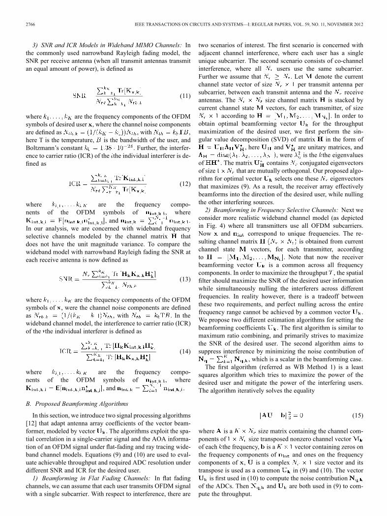
of ADC bits (both the I and Q ADC have an equal number ofbits) under two interferes at ICR dB. Fig. 8(b) shows thatthe throughput gain compared to a SISO system is largest ina quantization noise limited scenario. From Fig. 9(a) we canderive that at throughput of 2 bits/s/Hz, an analog spatial fil-tering system can perform equal to SISO system with 3 bits perADC less. Since we consider a large ICR of 40 dB, it reason-able to assume the interference is in close proximity to the re-ceiver. Therefore, the delay spread of the interferer will be muchsmaller than that of the desired user. To take this into account,the significant multipaths for the interferers are set to two and forthe desired user to five in (6). Results are shown in Table I. Thisresult is significant since it indicates that the power savings forthe ADC can potentially be an order of magnitude. A commonlyaccepted model for the power consumption of an ADC assumesexponential relationship with the number of bits. A commonlyaccepted ADC power model is
(20)
2770 IEEE TRANSACTIONS ON CIRCUITS AND SYSTEMS—I: REGULAR PAPERS, VOL. 59, NO. 11, NOVEMBER 2012
Fig. 9. OFDM signals and wideband ray tracing channel model (all signalsare frequency selective). (a) Throughput and (b) difference in Throughput ofbeamformer, compared to a SISO system. For two interferers with ICR dBand SNR dB.
TABLE ISNR VERSUS NUMBER OF BITS REQUIRED TO ACHIEVE A GIVEN THROUGHPUTIN THE BEAMFORMER CASE bits/s/Hz. OFDM SIGNALS AND WIDEBANDRAY TRACING CHANNEL MODEL (WANTED SIGNAL IS FREQUENCY SELECTIVE
AND INTERFERERS ARE FLAT FADING)
where is the sample frequency of the ADC, a technologyconstant, and the number of ADC bits [8], [9]. Sincethe power of ADC converters reduces with approximately 90%every decade, analog spatial filtering has the potential to accel-erate the reduction of overall system power reduction.4) Impact of Finite Resolution Phase Shifters: Up until now
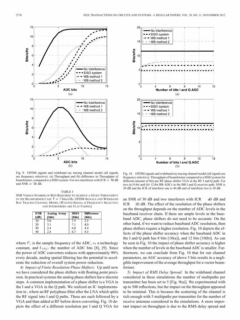
we have considered the phase shifters with floating point preci-sion. In practical systems the analog phase shifters have discretesteps. A common implementation of a phase shifter is a VGA inthe I and a VGA in the Q path. We realized an IC implementa-tion in , where an RF polyphase filter after the LNA which splitsthe RF signal into I and Q paths. These are each followed by aVGA and than added at RF before down converting. Fig. 10 de-picts the effect of a different resolution per I and Q VGA for
Fig. 10. OFDM signals and wideband ray tracing channel model (all signals arefrequency selective). Throughput of beamformer compared to a SISO system fordifferent amount of bits per RF phase shifter VGA in the RF I and Q path. Fortwo (a) 8-bit and (b) 12-bit BB ADCs in the BB I and Q receiver path. SNR is30 dB and the ICR of interferer one is 40 dB and of interferer two is 30 dB.
an SNR of 30 dB and two interferers with ICR dB andICR dB. The effect of the resolution of the phase shifterson the throughput depends on the number of ADC levels in thebaseband receiver chain. If there are ample levels in the base-band ADC, phase shifters do not need to be accurate. On theother hand, if we want to reduce baseband ADC resolution, thenphase shifters require a higher resolution. Fig. 10 depicts the ef-fects of the phase shifter accuracy when the baseband ADC inthe I and Q path has 8 bits [10(a)], and 12 bits [10(b)]. As canbe seen in Fig. 10 the impact of phase shifter accuracy is higherwhen the number of levels in the baseband ADC is smaller. Fur-thermore, we can conclude from Fig. 10 that for our channelparameters, an AGC accuracy of above 5 bits results in a negli-gible improvement of the average throughput for a vector beam-former.5) Impact of RMS Delay Spread: In the wideband channel
considered in these simulations the number of multipaths pertransmitter has been set to 5 [Fig. 9(a)]. We experimented withup to 500 reflections, but the impact on the throughput appearedto be minimal. This is because the scattering of the channel isrich enough with 5 multipaths per transmitter for the number ofreceive antennas considered in the simulations. A more impor-tant impact on throughput is due to the RMS delay spread and

VAN DEN HEUVEL et al.: FULL MIMO SPATIAL FILTERING APPROACH FOR DR REDUCTION IN WIDEBAND CRs 2771
Fig. 11. OFDM signals and wideband ray tracing channel model (all signalsare frequency selective). Effect of changing delay spread on throughput for 400reflective surfaces, SNR is 30 dB. For two 8-bit ADCs in the I and Q path. ICRof interferer one and two is 40 dB.
the corresponding coherence bandwidth as is depicted in Fig. 11[18]. At sufficiently large RMS delay spread, say sin Fig. 11 the coherence bandwidth is in the order of a singlefrequency bin. Even at these small coherence bandwidths, thespatial filter appears to still provide a significant gain. This re-sult may be counterintuitive, as one might expect that a commonnon-frequency selective spatial filter setting for seemingly i.i.d.random frequency bins would have no significant effect. Our ob-servation that spatial filtering is nonetheless effective can be ex-plained because the system can still exploit the non-uniformityof the angular spread if dominant signals arrive from a few par-ticular angles. Moreover, although the correlation of all channelrealizations between frequency bins will approach zero at largeRMS delay spread, the instantaneous signal correlation for aspecific channel realization is not necessarily zero, in which caseit can be exploited by the spatial filter.Although our focus here is primarily on indoor environments,
spatial filtering can also be effective in other propagation envi-ronments. In the IEEE 802.22 standard, which is primarily de-signed for low populated rural areas [28], most primary users,such as TV broadcasters and FM radio stations, which interferewith the secondary CR, tend to have a small RMS delay spreadand a small AOA spread [29].
C. Full MIMO Spatial Filtering Wideband Channel
Next we characterize the performance of a full MIMO spa-tial filter. Here, the ACMM performs spatial filtering while al-lowing reception of all data streams simultaneously. For wide-band channel model we use ray tracer from Fig. 5.1) Impact of Number of ADC Bits: We analyze the required
number of ADC bits required to achieve given throughput understrong inband interferers.We assume both the I andQADChavean equal number of bits. Since we assume a large ICR of 40 dBit is reasonable to assume the interference is in close proximityto the receiver. Therefore, the delay spread of the interferer willbe much smaller than that of the desired user. To account for thiseffect, we assume that in the MIMO wideband channel modelthere are 2 reflections per interferer and 40 reflection for thedesired user. Results in Fig. 12 show that the throughput gain
Fig. 12. OFDM signals and wideband ray tracing channel model (wantedsignal is frequency selective and interferers are flat fading). Throughput ofACMM-MIMO compared to a regular and interference free MIMO system atSNR is (a) 20 dB and (b) 30 dB, for a 4 4 MIMO system. Two interferersat ICR dB.
TABLE IISNR VERSUS NUMBER OF BITS REQUIRED TO ACHIEVE A GIVEN
THROUGHPUT FOR A 4 4 MIMO SYSTEM IN THE FULL MIMO SPATIALFILTERING CASE bits/s/Hz. OFDM SIGNALS AND WIDEBAND RAYTRACING CHANNEL MODEL (WANTED SIGNAL IS FREQUENCY SELECTIVE
AND INTERFERERS ARE FLAT FADING)
compared to a regular MIMO system is the largest in a quantiza-tion noise limited scenario. Table II shows that the difference innumber of bits required between the ACMM and regular MIMOis smaller at lower SNR values. This is because our algorithmis trying to suppress the interferers, but at lower SNR values itmay be more effective to focus more on maximum ratio com-bining than interference nulling. From Fig. 12 we can derive toachieve the throughput of 5 bits/s/Hz, an analog spatial filteringsystem performs equally as 4 4 MIMO system with 3 bits perADC less (Table II). We believe this result is significant sincethis indicates that the power consumption of the MIMO ADCscan potentially be reduced with over 85%.

2772 IEEE TRANSACTIONS ON CIRCUITS AND SYSTEMS—I: REGULAR PAPERS, VOL. 59, NO. 11, NOVEMBER 2012
Fig. 13. Throughput of beamformer and ACMM-MIMO compared to a reg-ular and interference free SISO and MIMO system at SNR is 30 dB, for a 44 MIMO system and 4 Rx Beamformer. OFDM signals and wideband ray
tracing channel model (wanted signal is frequency selective and interferers areflat fading). Two interferers at ICR dB.
2) Comparison Between Full MIMO Spatial Filter andAnalog Beamforming: In Fig. 13, a 4 4 full MIMO spatialfilter is compared to a 4 1 beamformer. Again, we assumethat in the MIMO wideband channel model there are 2 reflec-tions per interferer and 40 reflection for the desired user. Thefigure shows that at low ADC bits, when the quantization noiseis dominant, the beamformer and ACMM have comparableperformances. However, with more ADC bits the MIMO re-ceiver clearly outperforms the beamformer. The performanceis comparable at lower number of ADC bits because the quanti-zation noise is so dominant that only the strongest eigenvectorcontributes to the throughput. Since the analog beamfomerfocuses mainly on the strongest eigenvector its performanceis similar to the ACMM, but with 3 ADCs less. From thisexample it can be seen that at channel realizations were thereis a large variation in the dynamic range of the eigenvalues, itis beneficial to switch off branches in the ACMM in order toopportunistically save power, since they do not contribute tothe overall system throughput. Most MIMO channels tend tohave a Wishart distribution. The empirical distribution functionof the eigenvalues of Wishart matrices has an asymptoticdistribution. This implies a large condition number and thusoften leads to a large difference in the dynamic range of theeigenvalues for a given channel state. After evaluating theeigenvalue distribution of the channel, the signal to thermaland quantization noise ratio at the receiver can be used by thereceiver as a measure to decide to switch on and off branches.Another option is to dynamically allocate the total amount ofquantization levels in the receiver across the ADCs to furtherminimize the quantization noise contribution. This may allowfor a reduction in the total amount of levels used and thus inthe total ADC requirements.
V. CONCLUSION
In this paper, we have shown that wideband CR that em-ploy analog spatial filtering for the dynamic range reduction canachieve similar system throughput as systems without spatialfiltering with significantly less quantization bits in the basebandADC. Simulations show that for realistic indoor scenarios withan SNR of 20 dB and two interferers with an ICR of 40 dB, areceiver using analog vector beamforming spatial filtering canachieve similar throughput compared to SISO but with 4 ADCbits less, corresponding to a power reduction of over 90%. Fur-ther, simulations indicate that a MIMO system with an analogcomplex matrix multiplier that allows for full MIMO spatialfiltering can achieve a similar throughput as a regular MIMOsystem with 3 ADC bit less, corresponding to a power reductionof over 85%. Under low SNR, in a noise limited regime, oppor-tunistic on and off switching of branches in the ACMM basedon the dynamic range of the eigenvalues in the current channelstate can contribute to further power reduction. Another optionis to dynamically allocate quantization levels among branchesto further minimize the quantization noise contributed by theADCs and thus its requirements. Since ADC power consump-tion reduces at a rate of an order of magnitude per decade, we be-lieve that the algorithms and architectures for spatial filtering weproposed in this paper can largely contribute to overall systempower reduction, and accelerate the introduction of CR in thehand held market.
ACKNOWLEDGMENT
The authors would like to thank F. Willems for stimulatingdiscussions.
REFERENCES[1] D. Cabric, M. S. Chen, D. A. Sobel, S. Wang, J. Yang, and R. W.
Brodersen, “Novel radio architectures for UWB, 60 GHz, and cogni-tive wireless systems,” EURASIP J. Wireless Commun. Netw., Spec.Iss. CMOS RFCircuits for Wireless Applicat., vol. 2006, pp. 1–18, Apr.2006.
[2] W.-B. Chien, C.-K. Yang, and Y.-H. Huang, “Energy-saving cooper-ative spectrum sensing processor for cognitive radio system,” IEEETrans. Circuits Syst. I: Reg. Papers, vol. 58, no. 4, pp. 711–723, Apr.2011.
[3] R. Mahesh and A. Vinod, “A low-complexity flexible spec-trum-sensing scheme for mobile cognitive radio terminals,” IEEETrans. Circuits Syst. II: Exp. Briefs, vol. 58, no. 6, pp. 371–375, Jun.2011.
[4] B. Razavi, “CMOSRF receiver design for wireless LAN applications,”in Proc. IEEE Radio Wireless Conf. (RAWCON 99), Aug. 1999, pp.275–280.
[5] B. Razavi, “Challenges in the design of cognitive radios,” in Proc.IEEE Custom Intergr. Circuits Conf. (CICC), Sep. 2009, pp. 391–398.
[6] J. Yang, R. Brodersen, and D. Tse, “Addressing the dynamic rangeproblem in cognitive radios,” in Proc. IEEE Int. Conf. Commun. (ICC’07), Jun. 2007, pp. 5183–5188.
[7] C. Lelandais-Perrault, T. Petrescu, D. Poulton, P. Duhamel, and J.Oksman, “Wideband, bandpass, and versatile hybrid filter bank a/dconversion for software radio,” IEEE Trans. Circuits Syst. I: Reg.Papers, vol. 56, no. 8, pp. 1772–1782, Aug. 2009.
[8] R. Walden, “Analog-to-digital converter survey and analysis,” IEEE J.Sel. Areas Commun., vol. 17, no. 4, pp. 539–550, Apr. 1999.
[9] B. Le, T. Rondeau, J. Reed, and C. Bostian, “Analog-to-digital con-verters,” IEEE Signal Process. Mag., vol. 22, no. 6, pp. 69–77, Nov.2005.
[10] D. Cabric, I. O’Donnell, M. S.-W. Chen, and R. W. Brodersen, “Spec-trum sharing radios,” IEEE Circuits Syst. Mag., vol. 6, no. 2, p. 30, Jul.2006.

VAN DEN HEUVEL et al.: FULL MIMO SPATIAL FILTERING APPROACH FOR DR REDUCTION IN WIDEBAND CRs 2773
[11] V. Venkateswaran and A.-J. van der Veen, “Analog beamformingin MIMO communications with phase shift networks and onlinechannel estimation,” IEEE Trans. Signal Process., vol. 58, no. 8, pp.4131–4143, Aug. 2010.
[12] J. van den Heuvel and D. Cabric, “Spatial filtering approach for dy-namic range reduction in cognitive radios,” in Proc. 21st Annu. IEEEInt. Symp. Personal, Indoor, Mobile Radio Commun. (PIMRC), 2010,Sep. 2010, pp. 2657–2662.
[13] J. van den Heuvel, J.-P. Linnartz, and P. Baltus, “Theoretical model formaximum throughput of a radio receiver with limited battery power,”inProc. 31stWIC Symp. Inf. Theory Benelux, IEEEBenelux Inf. TheoryCh. and WIC SITB 2010, May 2010.
[14] J. van den Heuvel, J.-P. Linnartz, and P. Baltus, “Optimizingthroughput for limited receiver circuit power,” in Proc. IEEE Int.Symp. Circuits Syst. (ISCAS), 2010, May 2010, pp. 1013–1016.
[15] J. van den Heuvel, J.-P. Linnartz, and P. Baltus, “Optimal transmissionrate for ultra low-power receivers,” inProc. 21st Annu. IEEE Int. Symp.Personal, Indoor, Mobile Radio Commun. (PIMRC), 2010, Sep. 2010,pp. 93–98.
[16] B. Razavi, “Design of millimeter-wave CMOS radios: A tutorial,”IEEE Trans. Circuits Syst. I: Reg. Papers, vol. 56, no. 1, pp. 4–16,Jan. 2009.
[17] D. Gesbert, H. Bolcskei, D. Gore, and A. Paulraj, “Outdoor MIMOwireless channels: Models and performance prediction,” IEEE Trans.Commun., vol. 50, no. 12, pp. 1926–1934, Dec. 2002.
[18] J. van den Heuvel, J.-P. Linnartz, and P. Baltus, “The effect of RMSdelay spread on spatial filtering,” in Proc. 32nd WIC Symp. Inf. TheoryBenelux, IEEE Benelux Information Theory Ch. and WIC SITB 2011,May 2011.
[19] H. Hashemi, “The indoor radio propagation channel,” Proc. IEEE, vol.81, no. 7, pp. 943–968, Jul. 1993.
[20] G. E. Athanasiadou, A. R. Nix, and J. P. McGeehan, “A microcellularray-tracing propagation model and evaluation of its narrow-band andwide-band predictions,” IEEE J. Sel. Areas Commun., vol. 18, no. 3,pp. 322–335, Mar. 2000.
[21] D. Bliss and K. Forsythe, “Information theoretic comparison of mimowireless communication receivers in the presence of interference,” inProc. Conf. Record 38th Asilomar Conf. Signals, Syst., Comput., Nov.2004, vol. 1, pp. 866–870.
[22] S. Govindasamy, D. Bliss, andD. Staelin, “Spectral-efficiency ofmulti-antenna links in ad-hoc wireless networks with limited tx csi,” in Proc.Conf. Rec. 43rd Asilomar Conf. Signals, Syst., Comput., Nov. 2009, pp.1714–1718.
[23] X. Shao and C. H. Slump, “Quantization effects in OFDM systems,”in Proc. WIC Symp. Inf. Theory Benelux (IEEE Benelux Inf. TheoryChapter and WIC SITB 2008), May 2008.
[24] X. Shao, R. Schiphorst, and C. H. Slump, “Energy efficient error cor-rection in mobile TV,” in Proc. IEEE Int. Conf. Commun. (ICC), June2009, pp. 1–6.
[25] G. Foschini and M. Gans, “On limits of wireless communications in afading environment when using multiple antennas,”Wireless PersonalCommun., vol. 6, pp. 233–235, Mar. 1998.
[26] I. Telatar, “Capacity of multi-antenna Gaussian channels,” Eur. Trans.Telecomm., vol. 10, pp. 585–595, Nov.–Dec. 1999.
[27] A. Goldsmith, S. Jafar, N. Jindal, and S. Vishwanath, “Capacity limitsof MIMO channels,” IEEE J. Sel. Areas Commun., vol. 21, no. 6, pp.684–702, Jun. 2003.
[28] Y.-C. Liang, A. T. Hoang, and H.-H. Chen, “Cognitive radio on TVbands: A new approach to provide wireless connectivity for ruralareas,” IEEE Trans. Wireless Commun., vol. 15, no. 3, pp. 16–22, Jun.2008.
[29] A. Molisch, L. Greenstein, and M. Shafi, “Propagation issues for cog-nitive radio,” Proc. IEEE, vol. 97, no. 5, pp. 787–804, May 2009.
Johan H. C. van den Heuvel (M’01) was born inOss, The Netherlands, on February 5th, 1981. Hereceived the M.S. degree in electrical engineeringfrom Eindhoven University of Technology, Eind-hoven, The Netherlands, in 2006, and the Ph.D.degree from Eindhoven University of Technology,Eindhoven, The Netherlands, in 2012.In 2011, he moved to IMEC-NL where he is
working as a Wireless Research Scientist. Hiscurrent research interests include low-power andhigh-speed mixed-signal circuits and architectures,
multiple antennas system implementations, and digital baseband algorithms.
Jean-Paul M. G. Linnartz(S’85–M’87–SM’99–F’11) received theM.Sc. degree (cum laude) from EindhovenUniversity of Technology, Eindhoven, TheNetherlands, in 1986 and the Ph.D. degree (cumlaude) from the Delft University of Technology,Delft, The Netherlands, in December 1991.He is a part-time Professor at Eindhoven Univer-
sity of Technology in the Signal Processing Systems(SPS) Group and a Research Fellow at Philips Re-search, Eindhoven. As a Senior Director at Philips
Research, he has led research groups in the area of information security, wire-less connectivity, electronic systems, and silicon integration. He joined Philipsin 1995. He applied communication signal detection principles in the field ofelectronic watermarking and he invented various attacks and security measures.His work on privacy protection in biometric databases and on hardware secu-rity for integrated circuits led to the creation of startup ventures. He proposedalgorithms to mitigate Doppler intercarrier interference in OFDM reception forNXP chip sets for mobile DVB television reception. He holds more than 30granted U.S. patents, some of which are actively used in the industry and inan international standard. From 1992 to 1993, he was an Assistant Professor atThe University of California at Berkeley. In 1993, he introduced Multi-CarrierCDMA. From 1988 to 1991 and in 1994, he was an Assistant and AssociateProfessor at Delft University of Technology, respectively.Prof. Linnartz became a Fellow of the IEEE for leadership in security with
noisy data.
Peter G. M. Baltus (M’08–SM’11) was born inSittard, The Netherlands, on July 5th, 1960. He re-ceived the M.S. degree in electrical engineering fromEindhoven University of Technology, Eindhoven,The Netherlands, in 1985, and the Ph.D. degree fromEindhoven University of Technology in 2004.He worked for 22 years at Philips and later NXP
in Eindhoven, Nijmegen, Tokyo, and Sunnyvale invarious functions, including Research Scientist, Pro-gram Manager, Architect, Domain Manager, GroupLeader and Fellow. In 2007, he started his current job
at the Eindhoven University of Technology as a Professor in high-frequencyelectronics and Director of the Centre for Wireless Technology, Eindhoven. Heholds 16 patents and coauthored more than 70 papers.
Danijela Cabric received the Dipl.Ing. degree fromthe University of Belgrade, Belgrade, Serbia, in1998, the M.Sc. degree in electrical engineeringfrom the University of California, Los Angeles(UCLA), in 2001, and the Ph.D. degree in electricalengineering from University of California, Berkeley,in 2007, where she was a member of BerkeleyWireless Research Center.In 2008, she joined the faculty of Electrical Engi-
neering, UCLA, as an Assistant Professor. Her keycontributions involve the novel radio architecture,
signal processing, and networking techniques to implement spectrum sensingfunctionality in cognitive radios.Prof. Cabric was awarded a Samueli Fellowship in 2008 and an Okawa Foun-
dation research grant in 2009.