Embed Size (px)
Citation preview
1226
www.MaterialsViews.comwww.advenergymat.de
FULL
PAPER
Seoung-Bum Son , Seul Cham Kim , Chan Soon Kang , Thomas A. Yersak , Yoon-Chang Kim , Chun-Gyoo Lee , Sung-Hwan Moon , Jong Soo Cho , Jeong-Tak Moon , Kyu Hwan Oh , and Se-Hee Lee *
A Highly Reversible Nano-Si Anode Enabled by Mechanical Confi nement in an Electrochemically Activated Li x Ti 4 Ni 4 Si 7 Matrix
This paper reports a Si-Ti-Ni ternary alloy developed for commercial applica-tion as an anode material for lithium ion batteries. Our alloy exhibits a stable capacity above 900 mAh g − 1 after 50 cycles and a high coulombic effi ciency of up to 99.7% during cycling. To enable a highly reversible nano-Si anode, melt spinning is employed to embed nano-Si particles in a Ti 4 Ni 4 Si 7 matrix. The Ti 4 Ni 4 Si 7 matrix fulfi lls two important purposes. First, it reduces the maximum stress evolved in the nano-Si particles by applying a compressive stress to mechanically confi ne Si expansion during lithiation. And second, the Ti 4 Ni 4 Si 7 matrix is a good mixed conductor that isolates nano-Si from the liquid electrolyte, thus preventing parasitic reactions responsible for the formation of a solid electrolyte interphase. Given that a coulombic effi ciency above 99.5% is rarely reported for Si based anode materials, this alloy’s performance suggests a promising new approach to engineering Si anode materials.
1. Introduction
Lithium ion batteries (LIBs) are an indispensable power source for a variety of hand-held electronic devices. Today, LIBs are being developed with new electrode materials to provide elec-tric vehicles (EV), hybrid electric vehicles (HEV) and plug-in hybrid electric vehicles (PHEV) with an affordable and energy
© 2012 WILEY-VCH Verlag GmbH & Co. KGaA, Weinheiwileyonlinelibrary.com
DOI: 10.1002/aenm.201200180
S.-B. Son , S. C. Kim , C. S. Kang , Dr. J. S. Cho , Prof. K. H. Oh Department of Materials Science and EngineeringSeoul National UniversitySeoul, 151-742, Korea S.-B. Son , T. A. Yersak , Prof. S.-H. Lee Department of Mechanical EngineeringUniversity of Colorado at BoulderBoulder, CO, 80309, USAE-mail: [email protected] Dr. Y.-C. Kim , Dr. C.-G. Lee , Dr. S.-H. Moon SAMSUNG SDI CO. LTDGiheung-gu, Yongin-si, Gyeonggi-do, 446-577, Korea Dr. J. S. Cho , Dr. J.-T. Moon MK electron316-2 Geumeo-ri, Pogok-myeon, Yongin-si, Gyeong gi-do, 449-810, Korea
dense storage system. [ 1 , 2 ] These applica-tions demand electrode materials with a higher specifi c energy than that provided by commercially available materials. And from a life cycle perspective, it is essential that LIBs are made with environmentally benign materials.
Currently, graphite is a popular anode material for commercial LIBs because it exhibits a stable capacity of 372 mAh g − 1 . Although graphite has proven to be a stable anode material, industry is interested in developing new anode materials with higher capacities. One of the most prom-ising materials studied to replace graphite is Silicon (Si). The experimentally verifi ed specifi c capacity of Si is 3579 mAh g − 1 (forming Li 15 Si 4 ) which is the highest spe-cifi c capacity known among materials to the date. [ 3 , 4 ] The utilization of Si is also
advantageous because it is non-toxic and the 2 nd most abun-dant element in the Earth’s crust. [ 5 , 6 ] However, Si has yet to be commercialized because it undergoes a volume expansion of 300% with the insertion of 3.7 mole Lithium (Li) per mole of Si. Such a large volume expansion results in mechanical fatigue which causes rapid capacity fade and continually subjects fresh Si surfaces to the parasitic reduction of liquid electrolyte. Poor coulombic effi ciency (CE) arises from the formation of a solid electrolyte interphase (SEI). The problem of rapid capacity fade and low CE must be solved before Si can be adopted as an anode in commercial LIBs. [ 7–10 ]
The development of Si anodes is primarily concerned with two tasks: First, with how to mitigate stress evolution in Si par-ticles during Li insertion and extraction. And second, with how to maintain a high CE over many cycles. Previous research has shown that nano-structured Si electrodes composed of Si nano-particles, Si nano-wires or Si nano-alloys can better accommo-date the stresses generated during cycling. Nano-Si electrodes also have better reaction kinetics because Li-ion diffusion pathways are shortened compared to the bulk. [ 11–17 ] Interesting prelithiation strategy has also been reported to improve the cycling performance of nano electrode materials. [ 18 , 19 ] However, nano-structured Si electrodes tend to be expensive to fabri-cate because the synthesis of many of these materials requires
m Adv. Energy Mater. 2012, 2, 1226–1231
www.MaterialsViews.comwww.advenergymat.de
FULL P
APER
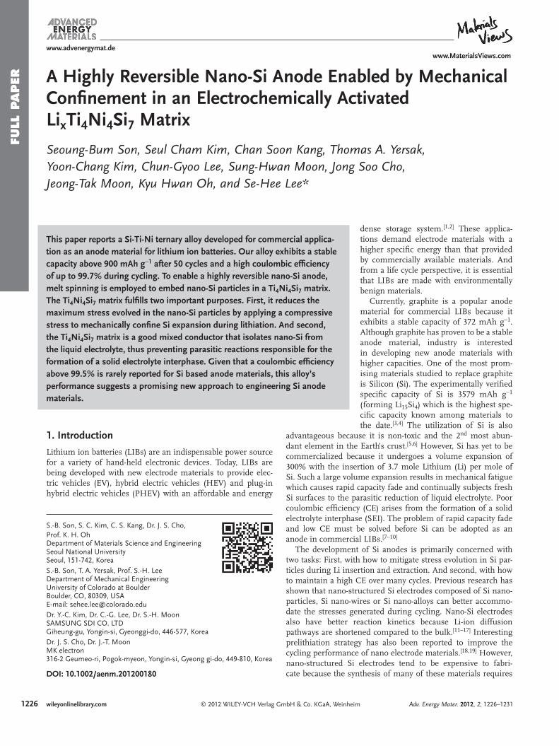
Figure 1 . (a) Simplifi ed schematics of melt spinner. (b) Achieved melt spun STN ribbon. (c) XRD pattern of ball milled melt spun STN powder that matched with Si phase (JCPDS, 27−1402) and Ti 4 Ni 4 Si 7 phase (JCPDS, 80−1015). (d) TEM image with HAADF mode of nano-Si and Ti 4 Ni 4 Si 7 . (e) EDS results of given area in Figure 1 d.
chemical or physical vapor deposition. For this reason, the aforementioned technologies are not suitable for large scale manufacture to meet commercial demand.
We have developed the Si-Ti-Ni (here after denoted as STN) ternary alloy to answer the call for a low-cost, high capacity anode with a high CE and good capacity retention. Our STN alloy exhibits a CE of up to 99.7% and a stable discharge capacity of 900 mAh g − 1 . To synthesize the STN alloy, we use melt spin-ning to embed nano-Si particles in a matrix of Ti 4 Ni 4 Si 7 . We chose the melt spinning method because it is inexpensive and can be implemented at standard temperature and pressure. Melt spinning is an established process used to synthesize alloys by rapidly solidifying molten metal solutions at a rate of 10 4 to 10 7 K s − 1 . Examples of materials synthesized by melt spinning include polymeric fi bers, magnetic alloys, and shape memory alloys . [ 20–23 ] Our STN alloy’s exceptional performance and ease of manufacture makes it an attractive prospect for commercialization in advanced LIBs. Our characterization of STN alloy anode also provides important mechanistic insight for the development of advanced anode materials for LIBs.
2. Results and Discussions
Figure 1 a depicts a simplifi ed schematic of the melt spinner used in this study. Melt spun STN ribbons are on average less than 1mm wide and 15 μ m thick (Figure 1 b). Powder X-ray dif-fraction (XRD) analysis was performed to determine the phases present in the STN alloy (Figure 1 c). We fi nd that the STN alloy is composed of crystalline Si (JCPDS, 27-1402) and Ti 4 Ni 4 Si 7 (JCPDS, 80-1015). [ 24 ] The Ti 4 Ni 4 Si 7 phase was previously reported by J. H. Westbrook et al., however, its electrochemical properties have not yet been reported to the best of our knowl-edge. [ 25 ] We used the Rietveld method to analyze XRD patterns and calculate the relative ratio of the component phases in our STN alloy. Supplementary Table S1 provides the information used for the Rietveld method analysis. The result informs us that the Si and Ti 4 Ni 4 Si 7 phases take possession of 46 and 54 weight percent (wt%) of the STN alloy respectively.
As shown in Figure 1 d, high resolution transmission elec-tron microscopy (HRTEM) analysis was performed using the high angle annular dark fi eld (HAADF) mode to observe the microstructure of the STN alloy in detail. It is observed that the structure is composed of two different compositions which are Si (weak contrast) and Ti 4 Ni 4 Si 7 (strong contrast). We fi nd that our STN ternary alloy is composed of 20−50 nm dia-meter Si nano particles embedded in a Ti 4 Ni 4 Si 7 matrix. Rapid solidifi cation from the molten state only allows for the forma-tion of nano sized Si. The remaining melt portion then forms the Ti 4 Ni 4 Si 7 matrix. Additional energy dispersive spectroscopy (EDS) results presented in Figure 1 e support the conclusion that the STN alloy is composed of nano-Si and Ti 4 Ni 4 Si 7 .
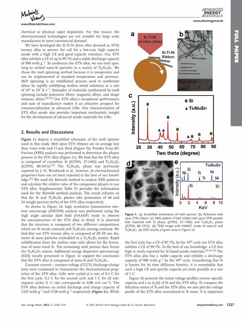
Constant current - constant voltage (CCCV) discharge-charge tests were conducted to characterize the electrochemical prop-erties of the STN alloy. Cells were cycled at a rate of 0.1 C for the fi rst cycle, 0.2 C for the second cycle and 1 C for all sub-sequent cycles (1 C rate corresponds to 0.88 mA cm − 2 ). The STN alloy delivers an initial discharge and charge capacity of 1325 mAh g − 1 and 1158 mAh g − 1 respectively ( Figure 2 a). While
© 2012 WILEY-VCH Verlag GmAdv. Energy Mater. 2012, 2, 1226–1231
the fi rst cycle has a CE of 87.7%, by the 10 th cycle our STN alloy exhibits a CE of 99.7%. To the best of our knowledge, a CE this high is rarely reported for Si based anode materials. [ 14 , 26–29 ] The STN alloy also has a stable capacity and exhibits a discharge capacity of 900 mAh g − 1 by the 50 th cycle. Considering that Si is known for its slow diffusion kinetics, it is remarkable that such a high CE and specifi c capacity are both possible at a rate of 1 C.
Figure 2 b presents the initial voltage profi les (versus specifi c capacity and x in Li x Si) of Si and the STN alloy. To compare the lithiation extent of Si and the STN alloy, we also plot the voltage profi le of the STN alloy normalized to Si mass. It is important
1227bH & Co. KGaA, Weinheim wileyonlinelibrary.com
www.MaterialsViews.comwww.advenergymat.de
FULL
PAPER
Figure 2 . (a) Specifi c capacity and CE of STN anode versus cycle num-bers. (b) Voltage profi le of Si, STN and normalized STN to Si mass between 0.01 V and 1.5 V.
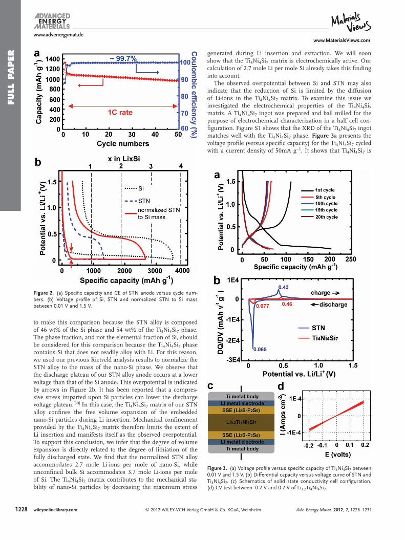
Figure 3 . (a) Voltage profi le versus specifi c capacity of Ti 4 Ni 4 Si 7 between 0.01 V and 1.5 V. (b) Differential capacity versus voltage curve of STN and Ti 4 Ni 4 Si 7 . (c) Schematics of solid state conductivity cell confi guration. (d) CV test between -0.2 V and 0.2 V of Li 3.2 Ti 4 Ni 4 Si 7 .
to make this comparison because the STN alloy is composed of 46 wt% of the Si phase and 54 wt% of the Ti 4 Ni 4 Si 7 phase. The phase fraction, and not the elemental fraction of Si, should be considered for this comparison because the Ti 4 Ni 4 Si 7 phase contains Si that does not readily alloy with Li. For this reason, we used our previous Rietveld analysis results to normalize the STN alloy to the mass of the nano-Si phase. We observe that the discharge plateau of our STN alloy anode occurs at a lower voltage than that of the Si anode. This overpotential is indicated by arrows in Figure 2 b. It has been reported that a compres-sive stress imparted upon Si particles can lower the discharge voltage plateau. [ 30 ] In this case, the Ti 4 Ni 4 Si 7 matrix of our STN alloy confi nes the free volume expansion of the embedded nano-Si particles during Li insertion. Mechanical confi nement provided by the Ti 4 Ni 4 Si 7 matrix therefore limits the extent of Li insertion and manifests itself as the observed overpotential. To support this conclusion, we infer that the degree of volume expansion is directly related to the degree of lithiation of the fully discharged state. We fi nd that the normalized STN alloy accommodates 2.7 mole Li-ions per mole of nano-Si, while unconfi ned bulk Si accommodates 3.7 mole Li-ions per mole of Si. The Ti 4 Ni 4 Si 7 matrix contributes to the mechanical sta-bility of nano-Si particles by decreasing the maximum stress
1228 © 2012 WILEY-VCH Verlag Gwileyonlinelibrary.com
generated during Li insertion and extraction. We will soon show that the Ti 4 Ni 4 Si 7 matrix is electrochemically active. Our calculation of 2.7 mole Li per mole Si already takes this fi nding into account.
The observed overpotential between Si and STN may also indicate that the reduction of Si is limited by the diffusion of Li-ions in the Ti 4 Ni 4 Si 7 matrix. To examine this issue we investigated the electrochemical properties of the Ti 4 Ni 4 Si 7 matrix. A Ti 4 Ni 4 Si 7 ingot was prepared and ball milled for the purpose of electrochemical characterization in a half cell con-fi guration. Figure S1 shows that the XRD of the Ti 4 Ni 4 Si 7 ingot matches well with the Ti 4 Ni 4 Si 7 phase. Figure 3 a presents the voltage profi le (versus specifi c capacity) for the Ti 4 Ni 4 Si 7 cycled with a current density of 50mA g − 1 . It shows that Ti 4 Ni 4 Si 7 is
mbH & Co. KGaA, Weinheim Adv. Energy Mater. 2012, 2, 1226–1231
www.MaterialsViews.comwww.advenergymat.de
FULL P
APER
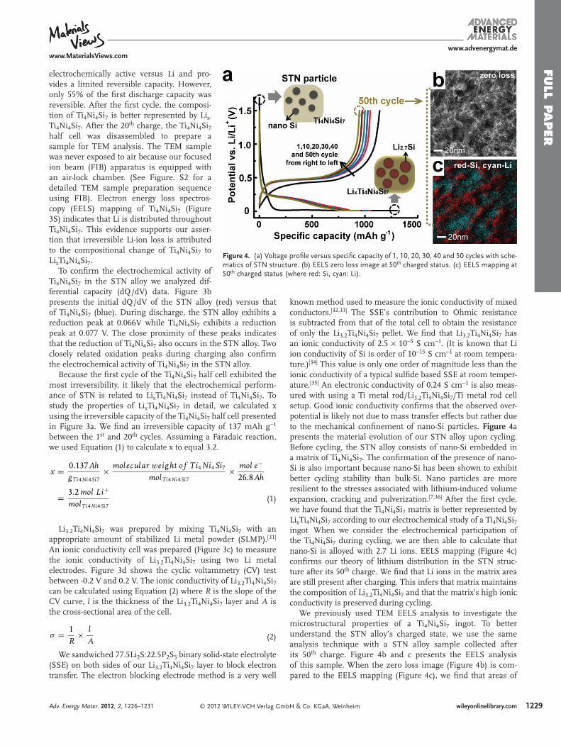
Figure 4 . (a) Voltage profi le versus specifi c capacity of 1, 10, 20, 30, 40 and 50 cycles with sche-matics of STN structure. (b) EELS zero loss image at 50 th charged status. (c) EELS mapping at 50 th charged status (where red: Si, cyan: Li).
electrochemically active versus Li and pro-vides a limited reversible capacity. However, only 55% of the fi rst discharge capacity was reversible. After the fi rst cycle, the composi-tion of Ti 4 Ni 4 Si 7 is better represented by Li x-
Ti 4 Ni 4 Si 7 . After the 20 th charge, the Ti 4 Ni 4 Si 7 half cell was disassembled to prepare a sample for TEM analysis. The TEM sample was never exposed to air because our focused ion beam (FIB) apparatus is equipped with an air-lock chamber. (See Figure. S2 for a detailed TEM sample preparation sequence using FIB). Electron energy loss spectros-copy (EELS) mapping of Ti 4 Ni 4 Si 7 (Figure 3 S) indicates that Li is distributed throughout Ti 4 Ni 4 Si 7 . This evidence supports our asser-tion that irreversible Li-ion loss is attributed to the compositional change of Ti 4 Ni 4 Si 7 to Li x Ti 4 Ni 4 Si 7 .
To confi rm the electrochemical activity of Ti 4 Ni 4 Si 7 in the STN alloy we analyzed dif-ferential capacity (dQ/dV) data. Figure 3 b
presents the initial dQ/dV of the STN alloy (red) versus that of Ti 4 Ni 4 Si 7 (blue). During discharge, the STN alloy exhibits a reduction peak at 0.066V while Ti 4 Ni 4 Si 7 exhibits a reduction peak at 0.077 V. The close proximity of these peaks indicates that the reduction of Ti 4 Ni 4 Si 7 also occurs in the STN alloy. Two closely related oxidation peaks during charging also confi rm the electrochemical activity of Ti 4 Ni 4 Si 7 in the STN alloy.Because the fi rst cycle of the Ti 4 Ni 4 Si 7 half cell exhibited the most irreversibility, it likely that the electrochemical perform-ance of STN is related to Li x Ti 4 Ni 4 Si 7 instead of Ti 4 Ni 4 Si 7 . To study the properties of Li x Ti 4 Ni 4 Si 7 in detail, we calculated x using the irreversible capacity of the Ti 4 Ni 4 Si 7 half cell presented in Figure 3 a. We fi nd an irreversible capacity of 137 mAh g − 1 between the 1 st and 20 th cycles. Assuming a Faradaic reaction, we used Equation (1) to calculate x to equal 3.2.
x = 0.137Ah
gTi4Ni4Si7× molecular weight o f Ti4 Ni4 Si7
molTi4Ni4Si7× mol e−
26.8Ah
= 3.2 mol Li+
molTi4Ni4Si7 (1)
Li 3.2 Ti 4 Ni 4 Si 7 was prepared by mixing Ti 4 Ni 4 Si 7 with an appropriate amount of stabilized Li metal powder (SLMP). [ 31 ] An ionic conductivity cell was prepared (Figure 3 c) to measure the ionic conductivity of Li 3.2 Ti 4 Ni 4 Si 7 using two Li metal electrodes. Figure 3 d shows the cyclic voltammetry (CV) test between -0.2 V and 0.2 V. The ionic conductivity of Li 3.2 Ti 4 Ni 4 Si 7 can be calculated using Equation (2) where R is the slope of the CV curve, l is the thickness of the Li 3.2 Ti 4 Ni 4 Si 7 layer and A is the cross-sectional area of the cell.
σ = 1
R× l
A (2)
We sandwiched 77.5Li 2 S:22.5P 2 S 5 binary solid-state electrolyte (SSE) on both sides of our Li 3.2 Ti 4 Ni 4 Si 7 layer to block electron transfer. The electron blocking electrode method is a very well
© 2012 WILEY-VCH Verlag GmAdv. Energy Mater. 2012, 2, 1226–1231
known method used to measure the ionic conductivity of mixed conductors. [ 32 , 33 ] The SSE’s contribution to Ohmic resistance is subtracted from that of the total cell to obtain the resistance of only the Li 3.2 Ti 4 Ni 4 Si 7 pellet. We fi nd that Li 3.2 Ti 4 Ni 4 Si 7 has an ionic conductivity of 2.5 × 10 − 5 S cm − 1 . (It is known that Li ion conductivity of Si is order of 10 − 15 S cm − 1 at room tempera-ture.) [ 34 ] This value is only one order of magnitude less than the ionic conductivity of a typical sulfi de based SSE at room temper-ature. [ 35 ] An electronic conductivity of 0.24 S cm − 1 is also meas-ured with using a Ti metal rod/Li 3.2 Ti 4 Ni 4 Si 7 /Ti metal rod cell setup. Good ionic conductivity confi rms that the observed over-potential is likely not due to mass transfer effects but rather due to the mechanical confi nement of nano-Si particles. Figure 4 a presents the material evolution of our STN alloy upon cycling. Before cycling, the STN alloy consists of nano-Si embedded in a matrix of Ti 4 Ni 4 Si 7 . The confi rmation of the presence of nano-Si is also important because nano-Si has been shown to exhibit better cycling stability than bulk-Si. Nano particles are more resilient to the stresses associated with lithium-induced volume expansion, cracking and pulverization. [ 7 , 36 ] After the fi rst cycle, we have found that the Ti 4 Ni 4 Si 7 matrix is better represented by Li x Ti 4 Ni 4 Si 7 according to our electrochemical study of a Ti 4 Ni 4 Si 7 ingot . When we consider the electrochemical participation of the Ti 4 Ni 4 Si 7 during cycling, we are then able to calculate that nano-Si is alloyed with 2.7 Li ions. EELS mapping (Figure 4 c) confi rms our theory of lithium distribution in the STN struc-ture after its 50 th charge. We fi nd that Li ions in the matrix area are still present after charging. This infers that matrix maintains the composition of Li 3.2 Ti 4 Ni 4 Si 7 and that the matrix’s high ionic conductivity is preserved during cycling.
We previously used TEM EELS analysis to investigate the microstructural properties of a Ti 4 Ni 4 Si 7 ingot. To better understand the STN alloy’s charged state, we use the same analysis technique with a STN alloy sample collected after its 50 th charge. Figure 4 b and c presents the EELS analysis of this sample. When the zero loss image (Figure 4 b) is com-pared to the EELS mapping (Figure 4 c), we fi nd that areas of
1229bH & Co. KGaA, Weinheim wileyonlinelibrary.com
1230
www.MaterialsViews.comwww.advenergymat.de
FULL
PAPER
strong contrast correspond to nano-Si and areas of weak con-trast correspond to the Li 3.2 Ti 4 Ni 4 Si 7 matrix. The zero loss image also does not show any evidence of cracks or material pulverization.
3. Conclusion
We embed nano-Si in a Ti 4 Ni 4 Si 7 matrix for three reasons. First, because the Ti 4 Ni 4 Si 7 matrix limits the extent of Si lithiation. At STN’s fully discharged state, one mole of Si is lithiated with 2.7 moles of Li ions (Li 2.7 Si) instead of the 3.7 moles of Li ions (Li 15 Si 4 ) in a typical Si electrode. Limiting the extent of lithia-tion minimizes the maximum stress generated by reducing the volume expansion experienced by a Si particle. Secondly, because the Li x Ti 4 Ni 4 Si 7 matrix facilitates fast and effi cient Li ion and electron transfer to nano-Si. We fi nd that Li 3.2 Ti 4 Ni 4 Si 7 functions as solid state ionic conductor with an ionic con-ductivity of 2.5 × 10 − 5 S cm − 1 and an electronic conductivity of 0.24 S cm − 1 at room temperature. And fi nally, because the Li x Ti 4 Ni 4 Si 7 matrix helps to reduce the formation of an SEI layer on the Si surface. The formation of a SEI layer on the surface of active materials typically increases interfacial resistance to charge transfer and also lowers the CE of the system. There-fore, reducing the exposed active Si surface area will mitigate the parasitic reaction responsible for SEI layer formation. The Li x Ti 4 Ni 4 Si 7 matrix coats much of the nano-Si surface and pre-vents the reduction of the organic electrolyte. This protection enables our system to have better mass transfer kinetics and a high CE. [ 37–39 ] As a result, our STN system demonstrates a specifi c capacity in excess of 900 mAh g − 1 after the 50 th dis-charge-charge cycle and a CE of 99.7% at a rate of 1C. We have presented a low-cost nanoscale Si anode. Previous nanoscale Si anodes suffer from capacity fade because full utilization of Si results in mechanical fatigue and because their large surface area reacts readily with organic liquid electrolyte. Creative, but expensive ways to mitigate stress evolution have been devised but few Si anodes with acceptable CE have been developed. The electrochemically activated Li x Ti 4 Ni 4 Si 7 matrix is an extraordi-nary material that both electrochemically and mechanically ena-bles the reversible and stable cycling of nano-Si for high energy density LIB.
4. Experimental Section Melt spun ribbon was obtained by a single roller melt-spinning technique. Copper quenching roller with a diameter of 400 mm is used for rapid solidifi cation at the ratio of 1500 rates per minute (RPM). This process is done under Ar atmosphere. The molten state of Si-Ti-Ni master alloy is used with an atomic ratio of 68%-16%-16% as a starting material, respectively.
Standard types of 2016 half coin cells with Li metal foil as a counter electrode were prepared for these experiments. The anode mixture was composed of STN, ketjen black and polyamide/imide (PAI) binder with a wt% ratio of 88%-4%-8%, and mixed with a 1-methyl-2-pyrrolidinone (NMP) solution. The mixture was coated on Cu foil and then dried under air. Considering weight ratio among materials, 1.0 mg cm − 2 of STN is applied on the single electrode. 1.5 M LiPF 6 in ethylene carbonate, diethyl carbonate and fl uoroethylene carbonate (5:70:25) was used as the electrolyte. [ 40 ] Constant current (CC) is applied during discharge
© 2012 WILEY-VCH Verlag wileyonlinelibrary.com
and charge between the voltage range of 0.01 V and 1.5 V. Constant voltage (CV) is applied until amount of 0.01c is achieved at 0.01 V and 20 minutes of holds are made at both 0.01 V and 1.5 V.
SLMP (FMC Lithium Corp.) is used to synthesize a Li 3.2 Ti 4 Ni 4 Si 7 . SLMP and Ti 4 Ni 4 Si 7 is mixed for half an hour and heat treated at 100 ° C for 2 hours in the Ar-fi lled glove box. Li 2 S (Aldrich, 99.999%) - P 2 S 5 (Aldrich, 99%) at a molar ratio of 77.5:22.5 respectively, is used as a SSE. These starting materials were combined into a stainless steel vial and planetary ball milling was carried out for 20 continuous hours. All pressing and testing operations were carried out with Ti metal bodies as current collectors and covered by a poly (aryl ether ether ketone) mold ( Φ = 1.3 cm). Li metal foil (Alfa Aesar) is used for electrodes. All assembly processes of solid state ionic conductivity cell were carried out in Ar-fi lled glove box.
A FIB (FEI, NOVA200 dual beam system) equipped with an air-lock chamber is used for TEM sample preparation. Ga ion source is used for FIB sectioning. The use of an air-lock system enables to observe lithiated STN structure without any exposure to the air. Air exposure to lithiated sample causes structure changes with oxidation, however this mobile air-lock system maintains a vacuum state while samples are loaded from glove box to FIB chamber. Our previous paper explains the sample prepare sequence in detail. [8]
The microstructure of STN structure was investigated by HR-TEM (JEOL 3000F equipped with EDS) operating at 300 keV and analytical TEM (TECNAI F20 equipped with EELS) operating at 200 keV. XRD data for phase determination was collected with X-ray diffractometer (XRD, Bruker, D8 Advance) with Cu-K α radiation.
Supporting Information Supporting Information is available from the Wiley Online Library or from the author.
Acknowledgements This research was supported by a grant from the Fundamental R&D Program for Technology of World Premier Materials funded by the Ministry of Knowledge Economy, Republic of Korea (10037919). This research was in part supported by WCU (World Class University) project through National Research Foundation of Korea funded by the Ministry of Education, Science and Technology (R31-2008-000-10075-0).
Received: March 15, 2012Published online: May 18, 2012
[ 1 ] J. M. Tarascon , M. Armand , Nature 2001 , 414 , 359 . [ 2 ] C. K. Chan , H. L. Peng , G. Liu , K. McIlwrath , X. F. Zhang ,
R. A. Huggins , Y. Cui , Nat. Nanotechnol. 2008 , 3 , 31 . [ 3 ] T. D. Hatchard , J. R. Dahn , J. Electrochem. Soc. 2004 , 151 ,
A838 . [ 4 ] M. N. Obrovac , L. Christensen , Electrochem. Solid State Lett. 2004 ,
7 , A93 . [ 5 ] A. H. Mayne , S. C. Bayliss , P. Barr , M. Tobin , L. D. Buckberry , Phys.
Status Solidi A-Appl. Res. 2000 , 182 , 505 . [ 6 ] U. Kasavajjula , C. S. Wang , A. J. Appleby , J. Power Sources 2007 , 163 ,
1003 . [ 7 ] S. Golmon , K. Maute , S. H. Lee , M. L. Dunn , Appl. Phys. Lett. 2010 ,
97 . [ 8 ] S. B. Son , J. E. Trevey , H. Roh , S. H. Kim , K. B. Kim , J. S. Cho ,
J. T. Moon , C. M. DeLuca , K. K. Maute , M. L. Dunn , H. N. Han , K. H. Oh , S. H. Lee , Adv. Energy Mater. 2011 , 1 , 1199 .
[ 9 ] V. A. Sethuraman , M. J. Chon , M. Shimshak , V. Srinivasan , P. R. Guduru , J. Power Sources 2010 , 195 , 5062 .
GmbH & Co. KGaA, Weinheim Adv. Energy Mater. 2012, 2, 1226–1231
www.MaterialsViews.comwww.advenergymat.de
FULL P
APER
[ 10 ] S. D. Beattie , D. Larcher , M. Morcrette , B. Simon , J. M. Tarascon , J. Electrochem. Soc. 2008 , 155 , A158 .
[ 11 ] J. E. Trevey , K. W. Rason , C. R. Stoldt , S. H. Lee , Electrochem. Solid State Lett. 2010 , 13 , A154 .
[ 12 ] H. Kim , J. Cho , Nano Lett. 2008 , 8 , 3688 . [ 13 ] X. H. Liu , L. Q. Zhang , L. Zhong , Y. Liu , H. Zheng , J. W. Wang ,
J. H. Cho , S. A. Dayeh , S. T. Picraux , J. P. Sullivan , S. X. Mao , Z. Z. Ye , J. Y. Huang , Nano Lett. 2011 , 11 , 2251 .
[ 14 ] A. Magasinski , P. Dixon , B. Hertzberg , A. Kvit , J. Ayala , G. Yushin , Nat. Mater. 2010 , 9 , 353 .
[ 15 ] H. Jung , Y. U. Kim , M. S. Sung , Y. Hwa , G. Jeong , G. B. Kim , H. J. Sohn , J. Mater. Chem. 2011 , 21 , 11213 .
[ 16 ] H. T. Nguyen , F. Yao , M. R. Zamfi r , C. Biswas , K. P. So , Y. H. Lee , S. M. Kim , S. N. Cha , J. M. Kim , D. Pribat , Adv. Energy Mater. 2011 , 1 , 1154 .
[ 17 ] B. S. Lee , S. B. Son , K. M. Park , W. R. Yu , K. H. Oh , S. H. Lee , J. Power Sources 2012 , 199 , 53 .
[ 18 ] L. Q. Mai , B. Hu , W. Chen , Y. Y. Qi , C. S. Lao , R. S. Yang , Y. Dai , Z. L. Wang , Adv. Mater. 2007 , 19 , 3712 .
[ 19 ] L. Q. Mai , L. Xu , B. Hu , Y. H. Gu , J. Mater. Res. 2010 , 25 , 1413 . [ 20 ] H. H. Liebermann , C. D. Graham , IEEE Trans. Magn. 1976 , 12 ,
921 . [ 21 ] B. Gupta , N. Revagade , J. Hilborn , Prog. Polym. Sci. 2007 , 32 ,
455 . [ 22 ] A. Manaf , R. A. Buckley , H. A. Davies , M. Leonowicz , J. Magn. Magn.
Mater. 1991 , 101 , 360 . [ 23 ] Z. L. Xie , J. VanHumbeeck , Y. Liu , L. Delaey , Scripta Mater. 1997 , 37 ,
363 . [ 24 ] E. Horache , T. P. Feist , J. A. Stuart , J. E. Fischer , J. Mater. Res. 1990 ,
5 , 1887 .
© 2012 WILEY-VCH Verlag GmAdv. Energy Mater. 2012, 2, 1226–1231
[ 25 ] J. H. Westbrook , R. K. DiCerbo , A. J. Peat , GE Technical Report 1958 , 58-RL-2117 , 1 .
[ 26 ] C. J. Yu , X. Li , T. Ma , J. P. Rong , R. J. Zhang , J. Shaffer , Y. H. An , Q. Liu , B. Q. Wei , H. Q. Jiang , Adv. Energy Mater. 2012 , 2 , 68 .
[ 27 ] X. L. Li , J. H. Cho , N. Li , Y. Y. Zhang , D. Williams , S. A. Dayeh , S. T. Picraux , Adv. Energy Mater. 2012 , 2 , 87 .
[ 28 ] T. H. Hwang , Y. M. Lee , B. S. Kong , J. S. Seo , J. W. Choi , Nano Lett. 2012 , 12 , 802 .
[ 29 ] H. Wu , G. Zheng , N. Liu , T. J. Carney , Y. Yang , Y. Cui , Nano Lett. 2012 , 12 , 904 .
[ 30 ] V. A. Sethuraman , V. Srinivasan , A. F. Bower , P. R. Guduru , J. Elec-trochem. Soc. 2010 , 157 , A1253 .
[ 31 ] C. R. Jarvis , M. J. Lain , Y. Gao , M. Yakovleva , J. Power Sources 2005 , 146 , 331 .
[ 32 ] D. J. Vischjager , A. A. van Zomeren , J. Schoonman , I. Kontoulis , B. C. H. Steele , Solid State Ion. 1990 , 40−41 , 810 .
[ 33 ] T. Inoue , J. I. Kamimae , M. Ueda , K. Eguchi , H. Arai , J. Mater. Chem. 1993 , 3 , 751 .
[ 34 ] I. Riess , Solid State Ion. 1991 , 44 , 199 . [ 35 ] J. Trevey , J. S. Jang , Y. S. Jung , C. R. Stoldt , S. H. Lee , Electrochem.
Comm. 2009 , 11 , 1830 . [ 36 ] H. Gleiter , Prog. Mater. Sci. 1989 , 33 , 223 . [ 37 ] Y. M. Lee , J. Y. Lee , H. T. Shim , J. K. Lee , J. K. Park , J. Electrochem.
Soc. 2007 , 154 , A515 . [ 38 ] F. Kong , R. Kostecki , G. Nadeau , X. Song , K. Zaghib , K. Kinoshita ,
F. McLarnon , J. Power Sources 2001 , 97−98 , 58 . [ 39 ] H. Nakai , T. Kubota , A. Kita , A. Kawashima , J. Electrochem. Soc.
2011 , 158 , A798 . [ 40 ] N. S. Choi , K. H. Yew , K. Y. Lee , M. Sung , H. Kim , S. S. Kim , J. Power
Sources 2006 , 161 , 1254 .
1231bH & Co. KGaA, Weinheim wileyonlinelibrary.com
![Universality in the 2D Ising model and conformal …smirnov/papers/universality-j.pdfUniversality in the 2D Ising model 517 dent Ising proved [19] in his PhD thesis the absence of](https://img.pdfslide.us/doc/110x75/5e5ab8ecd0f0bc3b3956d704/universality-in-the-2d-ising-model-and-conformal-smirnovpapersuniversality-jpdf.jpg)