Embed Size (px)
Citation preview
Fukushima Nuclear Accident Analysis Report (Interim Report)
December 02, 2011 The Tokyo Electric Power Company, Inc.
Forward
I would like to express my heartfelt sympathy to all of the people who were affected by the devastating earthquake on March 11 this year.
Reflecting on the accident at the Fukushima Daiichi Nuclear Power Station, the risk-reducing measures against a nuclear disaster consequently turned out to be insufficient. Almost all of the equipment and power sources that were expected to be activated in the case of an accident lost their functions, and thus, the event extended far beyond the existing framework for safety measures. We deeply apologize for the anxiety and inconvenience caused to the local residents around the power station, the residents of Fukushima Prefecture, and broader members of the society due to the extremely serious accident in which radioactive materials were released.
We will continue to work as hard as we can to ensure the stable cooling of the reactors at the Fukushima Daiichi Nuclear Power Station, to reduce the release of radioactive materials so that the citizens of Japan can feel secure, and to enable the evacuees to return home as soon as possible. We will also steadily work through mid- and long-term projects toward decommissioning.
TEPCO acknowledges that, in light of the severity of this accident, it is its social responsibility to conduct strict and thorough investigations and verifications of the accident, identify the causes of the accident, and reflect the lessons learned in its business operations, in order to prevent the recurrence of similar accidents. Based on this recognition, TEPCO set up a “Fukushima Nuclear Accident Investigation Committee” this June, and has been conducting such investigations and verifications.
While the first priority was put on the accident recovery work, investigations and analysis of various records and interviews with over 250 employees have been conducted under the very limited chance of field surveys because of high radiation condition.
Following the investigation, the committee’s conclusion was consulted on with the “Nuclear Safety and Quality Assurance Meeting Accident Investigation Verification Committee,” consisting of external experts, in order to have comments from a technical and independent point of view.
This interim report is intended to compile investigation results that have been verified so far. The report is mainly focused on the event causes and their preventive measures, especially from the point of facility design. It describes preparations for accidents, damage to the facilities by the earthquake and tsunami, accident management work, event progression of core damage, hydrogen explosions, and so on.
Since the investigation is ongoing, further new findings and topics not included in this interim report will be published in the future.
TEPCO had received support and understanding from many people with regard to its nuclear power generation. However, the accident has destroyed such public trust, for which we again would like to express our deep apologies.
Finally, we would like to express our gratitude toward the government, relevant national and international organizations, manufacturers, and the other people involved for their support and cooperation.
December 2, 2011
Chairman of the Tokyo Electric Power Company, Inc. Fukushima Nuclear Accident Investigation Committee
Masao Yamazaki
- Objectives and Framework of the Accident Investigation - (1) Objective
To clarify causes of the accident by investigating and verifying facts by ourselves as the central player of the accident, and to incorporate the lessons learned into future business operations.
(2) Framework [Fukushima Nuclear Accident Investigation Committee] (Committee members) Chairman: Executive Vice President Masao Yamazaki Members: Executive Vice President Masaru Takei Managing Director Hiroshi Yamaguchi Managing Director Yoshihiro Naito General Manager of Corporate Planning Department
General Manager of Engineering Department General Manager of the Corporate Affairs Department General Manager of the Nuclear Quality Management Department Total: 8 members
[Accident Investigation Verification Committee] A committee consisted of external experts was established under the “Nuclear Safety and Quality Assurance Meeting” as an advisory board to provide comments from a technical and independent point of view on the investigation results compiled by the “Fukushima Nuclear Accident Investigation Committee.”
(Committee members)
Chairman : Genki Yagawa (Professor Emeritus, University of Tokyo) Members: Yuriko Inubushi (Vice Chair, Consumption Science Federation)
Takeshi Kohno (Professor, Keio University) Yoshihisa Takakura
(Director, Tohoku Radiological Science Center) Nobuo Shuto (Professor Emeritus, Tohoku University) Hideki Nakagome (Attorney at Law) Masao Mukaidono (Professor, Meiji University)
(3) Method
The following investigations and verifications were implemented: Verification of records (charts, alarm records, operation log, etc.) Analysis (tsunami inversion analysis, seismic response analysis, core damage analysis,
etc.) Visual investigation of major indoor and outdoor facilities Interviews (discussions) with more than 250 people in total mainly from the emergency
response team at the power station
The investigation results were discussed first in the “Fukushima Nuclear Accident Investigation Committee,” and then consulted on with the “Accident Investigation Verification Committee” for a total of four times.
Table of Contents 1. Report objectives・・・・・・・・・・・・・・・・・・・・・・・・・・・・・・ 1 2. Overview of the Fukushima Nuclear Accident・・・・・・・・・・・・・・・・・・ 1 2.1 Outline of the Fukushima Daiichi Nuclear Power Station 2.2 Outline of the Fukushima Daini Nuclear Power Station 2.3 Overview of the Fukushima nuclear accident
3. Overview of the Tohoku-Chihou-Taiheiyo-Oki Earthquake・・・・・・・・・・・・・ 4
3.1 Scale of the earthquake and tsunami 3.2 Intensity of the earthquake at the power stations
3.3 Height of the tsunami at the power stations 3.4 Tsunami evaluation
4. Preparations for Accidents in the Power Station・・・・・・・・・・・・・・・・・ 18 4.1 Regulations 4.2 Facility design 4.3 Updates on new findings 4.4 Preparations of accident management 4.5 Accident management measures and the Fukushima accident 5. Preparation for Emergency Response・・・・・・・・・・・・・・・・・・・・・ 24 5.1 Preparation for emergency response on a nuclear disaster 5.2 Response during the accident 6. Impact of the Earthquake on Power Stations・・・・・・・・・・・・・・・・・・・ 27
6.1 Plant status right before the earthquake 6.2 Plant status right after the earthquake 6.3 Status of off-site power supply 6.4 Assessment of the impact on facilities by the earthquake
7. Direct Damage to the Facilities from the Tsunami・・・・・・・・・・・・・・・・ 44
7.1 Damage to the facilities at the Fukushima Daiichi Nuclear Power Station 7.2 Damage to the facilities at the Fukushima Daini Nuclear Power Station 7.3 Summary of the damage to the facilities from the tsunami
8. Response Status after the Tsunami Attack・・・・・・・・・・・・・・・・・・・・ 51
8.1 Response Status at Fukushima Daiichi Unit 1 8.2 Response Status at Fukushima Daiichi Unit 2 8.3 Response Status at Fukushima Daiichi Unit 3 8.4 Response Status at Fukushima Daiichi Unit 4 8.5 Response Status at Fukushima Daiichi Unit 5 8.6 Response Status at Fukushima Daiichi Unit 6 8.7 Response Status at Fukushima Daini Unit 1 8.8 Dose rate at site boundaries of the Fukushima Daiichi Nuclear Power Station during the
accident progress 8.9 Storage status of spent fuels
9. Evaluation of the Hydrogen Explosions・・・・・・・・・・・・・・・・・・・・ 95
9.1 Analysis on explosion events based on seismometers 9.2 Causes of the hydrogen explosions 10. Analysis of the Accident and Identification of Major Issues・・・・・・・・・・・・ 104
10.1 Issues concerning plant behavior at the time of the accident 10.2 Issues on facilities and functions 10.3 Issues based on factors impacting worker’s performance on the accident response 10.4 Summary of the analysis and the identification of issues 11. Countermeasures based on the Accident Causes・・・・・・・・・・・・・・・・ 142
11.1 Strategy for preventing core damage 11.2 Specific countermeasures in consideration of the Fukushima accident
12. Conclusions・・・・・・・・・・・・・・・・・・・・・・・・・・・・・・ 156 Attachments (submitted only in Japanese)
Response status at the Fukushima Daiichi Nuclear Power Station and the Fukushima Daini Nuclear Power Station
List of Supplementary Materials Attachments (submitted only in Japanese) [1. Report objectives] - [2. Overview of the Fukushima Nuclear Accident]
2-1 Outline of the Fukushima Daiichi Nuclear Power Station 2-2 Outline of the Fukushima Daini Nuclear Power Station
[3. Overview of the Tohoku-Chihou-Taiheiyo-Oki Earthquake] 3-1 Outline of the Tohoku-Chihou-Taiheiyo-Oki Earthquake 3-2 Comparison between the seismic observation records and the design seismic motion
at the Fukushima Daiichi Nuclear Power Station 3-3 Comparison between the seismic observation records and the design seismic motion
at the Fukushima Daini Nuclear Power Station 3-4 Tsunami investigation results at the Fukushima Daiichi Nuclear Power Station
3-5 Outdoor flooding conditions at the Fukushima Daiichi Nuclear Power Station 3-6 Conditions of the tsunami that hit the Fukushima Daiichi Nuclear Power Station 3-7 Results of the tsunami reproduction calculations at the Fukushima Daiichi Nuclear
Power Station 3-8 Tsunami investigation results at the Fukushima Daini Nuclear Power Station 3-9 Results of the tsunami reproduction calculations at the Fukushima Daini Nuclear
Power Station 3-10 Analysis regarding the tsunami differences 3-11 Main developments regarding the tsunami safety assessment 3-12 Wave source and wave source area proposed by various research organizations, etc. 3-13 Site height design of the Fukushima Daiichi Nuclear Power Station buildings
[4. Preparations for Accidents in the Power Station] 4-1 Redundancy, diversity, and independence of the engineered safety system 4-2 Installation conditions of “cooling” and “sealing” functions
4-3 Continuous risk reduction (continuous improvements)–Example of equipment renovations-
4-4 Background to accident management improvements 4-5 (1) Reinforcement of “cooling” functions 4-5 (2) Reinforcement of “sealing” functions 4-5 (3) Developed AM content–reinforcement of power supply functions- [5. Preparation for Emergency Response]
5-1 Nuclear disaster prevention organization (when primary emergency preparations are ordered)
5-2 No. 3 emergency preparations [6. Impact of the Earthquake on Power Stations]
6-1 (1) ~ (14) Fukushima Daiichi Unit 1 plant data 6-2 (1) ~ (13) Fukushima Daiichi Unit 2 plant data 6-3 (1) ~ (13) Fukushima Daiichi Unit 3 plant data 6-4 List of Fukushima Daiichi Nuclear Power Station external power access conditions 6-5 List of Fukushima Daini Nuclear Power Station external power access conditions 6-6 External power equipment damage conditions
6-7 (1) Seismic response analysis results of the Reactor Building and items important to seismic safety/pipe system using the Fukushima Daiichi Nuclear Power Station 2011 Great East Japan Earthquake observation records
6-7 (2) Report (outline) regarding the seismic response analysis results of the Reactor Building and items important to the seismic safety/pipe system using the Fukushima Daini Nuclear Power Station 2011 Great East Japan Earthquake observation records
6-7 (3) Outline of the “Report regarding reviews of the current seismic safety and reinforcements, etc., of the Reactor Building of the Fukushima Daiichi Nuclear Power Station”
6-8 (1) Fukushima Daiichi Unit 5 equipment conditions 6-8 (2) Fukushima Daiichi Unit 6 equipment conditions 6-8 (3) Fukushima Daiichi Unit 1 isolation condenser (IC) visual inspection results 6-8 (4) Fukushima Daiichi Unit 1, Unit 2, Unit 3 Turbine Building equipment conditions 6-8 (5) Fukushima Daiichi Units 1 ~ 4 outdoor equipment conditions 6-8 (6) Fukushima Daiichi Nuclear Power Station filtered water tank and pure water tank
conditions 6-8 (7) Fukushima Daiichi Nuclear Power Station outdoor fire protection system pipe
conditions 6-8 (8) Fukushima Daiichi Nuclear Power Station disaster prevention road conditions 6-9 (1) List of main equipment conditions at Fukushima Daiichi Unit 5 6-9 (2) List of main equipment conditions at Fukushima Daiichi Unit 6
[7. Direct Damage to the Facilities from the Tsunami] 7-1 Location of openings thought to be the flooding route into the main buildings at the
Fukushima Daiichi Nuclear Power Station 7-2 Fukushima Daiichi Nuclear Power Station seaside area and outdoor sea water system 7-3 Tsunami damage to the Fukushima Daiichi Nuclear Power Station power system 7-4 Damage to the Fukushima Daiichi Nuclear Power Station Electrical Power
Distribution System equipment 7-5 Location of openings thought to be the flooding route into the main buildings at the
Fukushima Daini Nuclear Power Station 7-6 Tsunami damage to the Fukushima Daini Nuclear Power Station power system 7-7 Damage to the Fukushima Daini Nuclear Power Station Electrical Power
Distribution System equipment 7-8 Conditions of the Core Standby Cooling System equipment, etc., at the Fukushima
Daiichi Nuclear Power Station 7-9 Conditions of the Core Standby Cooling System equipment, etc., at the Fukushima
Daini Nuclear Power Station [8. Response Status after the Tsunami Attack]
8-1 Aftershock conditions 8-2 High Pressure Coolant Injection system of Fukushima Daiichi Unit 1 8-3 Fukushima Daiichi Unit 1 primary containment vessel venting 8-4 Fukushima Daiichi Unit 1 primary containment vessel vent exhaust as seen in the
Fukuichi Live Camera photos 8-5 Fukushima Daiichi Unit 2 primary containment vessel venting 8-6 Fukushima Daiichi Unit 3 primary containment vessel venting 8-7 Fukushima Daiichi Unit 3 primary containment vessel vent exhaust as seen in the
Fukuichi Live Camera photos 8-8 (1) Spent fuel pool water level evaluation method 8-8 (2) Fukushima Daiichi Unit 1 spent fuel pool status survey
8-8 (3) Fukushima Daiichi Unit 2 spent fuel pool status survey 8-8 (4) Fukushima Daiichi Unit 3 spent fuel pool status survey 8-8 (5) Fukushima Daiichi Unit 4 spent fuel pool status survey 8-8 (6) Fukushima Daiichi Unit 5 spent fuel pool status survey 8-8 (7) Fukushima Daiichi Unit 6 spent fuel pool status survey 8-8 (8) Fukushima Daiichi shared pool status survey 8-8 (9) Dry storage cask storage building status survey
[9. Evaluation of the Hydrogen Explosions] - [10. Analysis of the Accident and Identification of Major Issues]
10-1 Changes in the Fukushima Daiichi Nuclear Power Station Unit 1 plant data 10-2 Isolation condenser 10-3 Isolation condenser motor-operated valve interlock block diagram 10-4 Development of Fukushima Daiichi Unit 1 isolation condenser (IC) valve
conditions 10-5 Investigation conditions regarding the decrease in the water level on the shell-side
of the isolation condenser (IC) 10-6 Changes in the Fukushima Daiichi Nuclear Power Station Unit 2 plant data 10-7 Changes in the Fukushima Daiichi Nuclear Power Station Unit 3 plant data 10-8 Changes in the Fukushima Daini Nuclear Power Station Unit 1 plant data 10-9 Maintenance of core cooling functions 10-10 Accident progression at the Fukushima Daiichi and Daini Nuclear Power Stations
(outline)
[11. Countermeasures based on the Accident Causes] 11-1 Countermeasures required for cold shutdown in the wake of the Fukushima Daiichi
accident 11-2 Summary of events, causes, and countermeasures at the Fukushima Daiichi Nuclear
Power Station Units 1 ~ 3 References 1(1) Fukushima Daiichi Nuclear Power Station equipment specifications 1(2) Fukushima Daini Nuclear Power Station equipment specifications
2(1) Comparison of Fukushima Daiichi Nuclear Power Station Emergency Safeguard Facilities and Reactor Auxiliary Facilities
2(2) Comparison of Fukushima Daini Nuclear Power Station Emergency Safeguard Facilities and Reactor Auxiliary Facilities
3 Outline of the Fukushima Daiichi and Daini Nuclear Power Station facility configuration
4(1) Indicated range of the Fukushima Daiichi Nuclear Power Station water-level gauge 4(2) Indicated range of the Fukushima Daini Nuclear Power Station water-level gauge
List of Major Related Reports (1) Plant data of Fukushima Daiichi Nuclear Power Station at the time of the
Tohoku-Chihou-Taiheiyou-Oki Earthquake (May 16, 2011, Tokyo Electric Power Company)
(2) Report on the analysis of observed seismic data collected at Fukushima Daiichi Nuclear
Power Station pertaining to the Tohoku-Chihou-Taiheiyou-Oki Earthquake (May 16, 2011, Tokyo Electric Power Company)
(3) Report on the analysis of observed seismic data collected at Fukushima Daini Nuclear
Power Station pertaining to the Tohoku-Chihou-Taiheiyou-Oki Earthquake (May 16, 2011, Tokyo Electric Power Company)
(4) Report regarding “Collection of reports pursuant to the provisions of Article 106,
Paragraph 3 of the Electricity Business Act” (May 16, 2011, Tokyo Electric Power Company)
(5) Analysis and evaluation of the operation record and accident record of Fukushima Daiichi
Nuclear Power Station at the time of Tohoku-Chihou-Taiheiyou-Oki-Earthquake (May 23, 2011, Tokyo Electric Power Company)
(6) Report on "Countermeasures based on a report on records of damages to power facilities
inside and outside of Fukushima Daiichi Nuclear Power Station (instruction)" (May 23, 2011, Tokyo Electric Power Company)
(7) Reports about the study regarding current seismic safety and reinforcement of reactor
buildings at Fukushima Daiichi Nuclear Power Station (May 28 , 2011, Unit 1 and Unit 4; July 13, 2011, Unit 3; August 26, 2011, Unit 2, Unit 5, and Unit 6, Tokyo Electric Power Company)
(8) Report on earthquake response analysis of the reactor building, important equipment and
piping system for earthquake-resistant safety using observed seismic data during the Tohoku-Taiheiyou-Oki Earthquake in the year 2011 (June 17, 2011, Unit 2 and Unit 4; July 28 , 2011, Unit 1 and Unit 3; August 18 , 2011, Unit 5 and Unit 6 Tokyo Electric Power Company)
(9) Report on investigation results regarding tsunami generated by the Tohoku-Taiheiyou-Oki-
Earthquake in Fukushima Daiichi and Daini Nuclear Power Stations (vol.2) (July 8, 2011, Tokyo Electric Power Company)
(10) Report on the impact of Tohoku-Chihou Taiheiyo-Oki Earthquake to nuclear reactor
facilities at Fukushima Daini Nuclear Power Station (August 12, 2011, Tokyo Electric Power Company)
(11) Report on the results of the earthquake response analysis of the reactor building, facilities
and pipes important to earthquake safety in Unit 1 at Fukushima Daini Nuclear Power Station using observed seismic data during the Tohoku-Taiheiyou-Oki Earthquake (August 18 , 2011, Tokyo Electric Power Company)
(12) The impact of the Tohoku-Chihou Taiheiyo-Oki Earthquake on nuclear reactor facilities at Fukushima Daiichi Nuclear Power Station (September 9, 2011, Tokyo Electric Power Company)
(13) Application status of the Accident Operation Manuals of Unit 1 at Fukushima Daiichi
Nuclear Power Station associated with the Tohoku-Chihou-Taiheiyou-Oki Earthquake (October 21, 2011, Tokyo Electric Power Company)
(14) Application status of the Accident Operation Manuals of Unit 2 at Fukushima Daiichi
Nuclear Power Station associated with the Tohoku-Chihou-Taiheiyou-Oki Earthquake (October 28, 2011, Tokyo Electric Power Company)
(15) Application status of the Accident Operation Manuals of Unit 3 at Fukushima Daiichi
Nuclear Power Station associated with the Tohoku-Chihou-Taiheiyou-Oki Earthquake (October 28, 2011, Tokyo Electric Power Company)
- 1 -
1 Report Objectives
This report identifies causes of the accident at the Fukushima Daiichi Nuclear Power Station (hereinafter referred to as “Fukushima accident”) based on the facts and analysis results that have been verified to date and proposes necessary countermeasures to enhance the safety of existing nuclear power plants.
Identifying the countermeasures is based on a discussion on technical issues for preventing core damage. It is important to reflect lessons learned from the Fukushima accident in both facilities and operations to prevent similar events from occurring again.
Since the investigation is still ongoing, further new findings and topics not included in this interim report, such as “release of radioactive materials,” “radiation control,” “human resources,” “material procurement,” “information disclosure/provision of information,” etc., will be published in the future.
2 Overview of the Fukushima Nuclear Accident 2.1 Outline of the Fukushima Daiichi Nuclear Power Station
The Fukushima Daiichi Nuclear Power Station (hereinafter referred to as “Fukushima
Daiichi NPS”) is located at approximately the middle of the Pacific coast of Fukushima Prefecture, and straddles the towns of Okuma and Futaba of the Futaba District. The site is semi-elliptical in shape, extending lengthwise along the coastline, and the site area is approximately 3.5 million m2.
The power station has six boiling water reactors (BWRs). Units 1 to 4 are located at the southern part of the power station in the order of Units 4, 3, 2, and 1 from the south. Units 5 and 6 are located at the northern part of the power station in the order of Units 5 and 6 from the south. The electric output of Unit 1 is 460 MWe. Units 2 to 5 have electric output of 784 MWe each, and they all have Mark I-type Primary Containment Vessels (PCVs). The electric output of Unit 6 is 1.1 GWe, and has a Mark II-type PCV. The total generation capacity of the site is 4.696 GWe. All the 6 units started their commercial operations in 1970’s, from Unit 1 in March 1971 to Unit 6 in October 1979.
When the disaster occurred on March 11, 2011, Units 1 to 3 were in rated output operation. Units 4 to 6 had been shut down for outage. [Attachment 2-1]
2.2 Outline of the Fukushima Daini Nuclear Power Station
The Fukushima Daini Nuclear Power Station (hereinafter referred to as “Fukushima
Daini NPS”) is located approximately 12km south of the Fukushima Daiichi NPS, and straddles the towns of Tomioka and Naraha. The site area is approximately 1.5 million m2.
The power station has four BWRs, which are arranged in the order of Units 1, 2, 3, and 4 from the south. All units have electrical output of 1.1 GWe, and Unit 1 has a Mark II-type PCV while Units 2 to 4 have improved Mark II-type PCVs. The total electrical capacity is 4.4 GWe, and the four units sequentially started operation from Unit 1 in April 1982 to Unit 4 in August 1987.
- 2 -
On March 11, Units 1 to 4 were all in operation at rated power output. [Attachment 2-2] 2.3 Overview of the Fukushima nuclear accident
On March 11, 2011, Units 1 to 3 were in operation at the Fukushima Daiichi NPS and Units 1 to 4 were in operation at the Fukushima Daini NPS. However, at 14:46, due to the Tohoku-Chihou-Taiheiyo-Oki Earthquake, whose focal area widely ranged from off-shore of Iwate Prefecture to Ibaraki Prefecture, all of the operating reactors were automatically shut down.
At Fukushima Daiichi NPS, all the off-site power supply was lost due to the earthquake. However, electric power necessary to maintain reactor safety was kept with the emergency diesel generators (EDGs). On the other hand, at Fukushima Daini NPS, off-site power supply was not lost.
Later, at the Fukushima Daiichi NPS, the subsequent arrival of the tsunami, which is one
of the largest in history, caused flooding of many cooling seawater pumps, EDGs, and power panels. It caused the station black out (SBO) of Units 1-5, and all the cooling functions using AC power were lost in these units. Furthermore, due to the flooding of the cooling seawater pumps by the tsunami, the function of the auxiliary cooling system to remove residual heat (decay heat) in the reactor to the sea was also lost. In addition, at Units 1 to 3, the loss of DC power resulted in the sequential shut down of core cooling functions which were designed to be operated without AC power supply.
Therefore, alternative water injection of freshwater and seawater using fire engines
through the Fire Protection (FP) line was conducted as a flexible applied action. However as it turned out, there remained the situation where water could not be injected into the reactor pressure vessels (RPVs) in Units 1 to 3 for a certain period of time. Consequently, the fuel in each unit was exposed without it being covered by water, and thereby the fuel cladding was damaged. And the radioactive materials in the fuel rods were released into the RPV, and the chemical reaction between the fuel cladding (zirconium) and steam caused the generation of a substantial amount of hydrogen.
As this caused the release of radioactive materials and hydrogen from the RPV into the PCV through the main steam safety relief valves (SRVs), and the internal pressure of the PCV increased, PCV venting* was attempted several times. In Units 1 and 3, the pressure of the PCVs decreased through the venting operation; however, in Unit 2, the pressure decrease of the PCV through the venting was not confirmed.
* The operation in which gas inside the PCV is discharged into the atmosphere in order to prevent damage to the PCV and a resulting uncontrollable release of radioactive materials.
Later, in Units 1 and 3, explosions, which appeared to be caused by hydrogen leakage from the PCV, destroyed the upper structures of their reactor buildings.
In addition, another explosion occurred at the upper structure of the reactor building in Unit 4 where all the fuel had been removed from the reactor and stored in the spent fuel pool (SFP) and kept under water in the SFP.
- 3 -
In Fukushima Daiichi Units 5 and 6, one of the EDGs for Unit 6 was in operation. By tying a power cable to Unit 5, water could be supplied into the core of both units. After the recovery of the residual (decay) heat removal function from the reactor to the sea, Units 5 and 6 reached cold shutdown. At the Fukushima Daini NPS, off-site power was continuously supplied and the scale of the tsunami was relatively small compared to the Fukushima Daiichi NPS. As a result of prompt responses, such as the restoration of temporary power of the emergency seawater system, cold shutdown was achieved for all the units.
However, at the Fukushima Daiichi Units 1 to 3, the accident escalated into a chain of
events, and developed into a serious nuclear disaster.
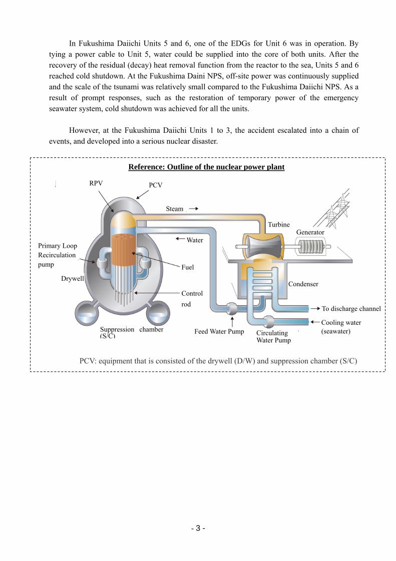
Reference: Outline of the nuclear power plant
PCV RPV
Steam
Turbine Generator
Condenser
To discharge channel
Cooling water (seawater)
Primary Loop Recirculation pump
Drywell
Suppression chamber (S/C)
Control
rod
Fuel
Water
Feed Water Pump Circulating Water Pump
PCV: equipment that is consisted of the drywell (D/W) and suppression chamber (S/C)
- 4 -
3 Overview of the Tohoku-Chihou-Taiheiyo-Oki Earthquake 3.1 Scale of the earthquake and tsunami
On March 11, 2011, the Tohoku-Chihou-Taiheiyo-Oki Earthquake occurred, the magnitude of the main shock of which was the largest ever recorded in Japan. A maximum seismic intensity of 7 on the Japanese scale was observed in Kurihara City of Miyagi prefecture. This earthquake caused large tsunamis on the Pacific coast from the Hokkaido, Tohoku, and Kanto region.
The focal area extended widely from the region off-shore of the Iwate to Ibaraki prefectures, with a length of approximately 500 km, width of approximately 200 km, and a maximum slip of approximately 20m or above. This was a massive M9.0 earthquake (fourth largest ever recorded in the world) that was caused by an interlocking movement of several regions off-shore of Miyagi prefecture, the southern trench off-shore of Sanriku to the east, off-shore of Fukushima prefecture, and off-shore of Ibaraki prefecture. Although the Headquarters for Earthquake Research Promotion, which is the government’s research institution, as well as TEPCO had evaluated seismic motion and tsunamis in individual regions based on past records of earthquakes and tsunamis, a tsunami caused by a conjunction of all these regions had not been taken into account.
The tsunami caused by this earthquake caused extensive damage to the area along the Pacific coast of the Tohoku region. The size of the tsunami was verified to be M9.1 on the tsunami magnitude, which is the fourth-largest tsunami ever recorded in the world and the greatest tsunami ever to reach Japan. [Attachment 3-1]
Time and date of the occurrence of the earthquake: March 11, 2011 14:46 Hypocenter: Off the Sanriku coast (focal depth of 24 km) Magnitude: 9 . 0 Distance from the Fukushima Daiichi NPS:
distance to the epicenter 178 km; distance to the hypocenter 180 km Distance from the Fukushima Daini NPS:
distance to the epicenter 183 km; distance to the hypocenter 185 km
3.2 Intensity of the earthquake at the power stations (1) Observation results at the Fukushima Daiichi Nuclear Power Station
Although the observed data on the foundation of the Fukushima Daiichi NPS reactor building (lowest basement floor) partially exceeded the maximum response acceleration with respect to the design-basis earthquake ground motion Ss, which is the seismic evaluation design basis, most data was below the design basis (maximum acceleration observed: 550 Gal on the first basement floor of the Unit 2 reactor building). Although the response spectrum of the seismic observation record partially exceeded the response spectrum of the design-basis earthquake ground motion Ss in some periodic bands, it was confirmed to be almost the same
- 5 -
level. It could be said that the seismic motion was almost the same level as the assumptions for the seismic evaluation of equipment.
The scale of the earthquake was extremely large. However, from the viewpoint of the impact on the Fukushima Daiichi NPS, the seismic movement observed at the facilities was about the same as the design-basis earthquake ground motion Ss. This is because Ss was determined also based on an assumption of an earthquake caused by the active faults near the power station and a certain margin was took into account. [Attachment 3-2]
(2) Observation results at the Fukushima Daini Nuclear Power Station
The observed data on the foundation of the Fukushima Daini NPS reactor building (lowest basement floor) was below the maximum response acceleration with respect to the design-basis earthquake ground motion Ss (maximum acceleration observed: 305 Gal on the second basement floor of the Unit 1 reactor building), and the seismic motion of the earthquake was within the postulated range of the seismic evaluation of equipment. [Attachment 3-3]
3.3 Height of the tsunami at the power stations (1) Tsunami observation results at the Fukushima Daiichi Nuclear Power Station
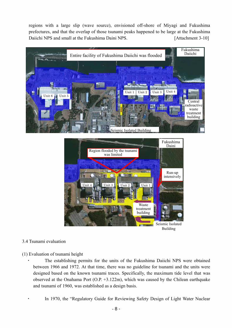
The tsunami at the Fukushima Daiichi NPS inundated the main-building area (O.P.+10 m around Units 1 to 4; O.P. +13 m around Units 5 and 6), and the entire main-building area was flooded. The flood height was approximately O.P. +11.5 m to +15.5 m around Units 1 to 4, and the flood depth was approximately 1.5 m to 5.5 m. As a result, the area surrounding major buildings was flooded significantly. (O.P.: Onahama Peil (0.727m below the Tokyo-bay Mean Sea Level)) [Attachment 3-4]
Pictures of tsunami near the central radioactive waste treatment building on the south side of Unit 4 shows a tank of approximately 5.5 m in height installed at the elevation of O.P.+10m being submerged by the tsunami. The flood depth in the vicinity of the building was more than 5m above the ground. [Attachment 3-5]
Around Units 5 and 6, the flood height was approximately O.P. +13 m to +14.5 m, and the flood depth was approximately 1.5 m or less, which was relatively shallow compared to the area around Units 1 to 4. However, the area around the major buildings was also flooded.
The tsunami height at the Fukushima Daiichi NPS could not be measured directly due to
damage to the tidal level gauge and wave level gauge caused by the earthquake or tsunami. However, since the tsunami pictures passing over the breakwater of O.P. +10 m were taken, it is confirmed that the tsunami height exceeded 10 m. [Attachment 3-6]
According to the results of the tsunami reproducing calculation that used the wave source obtained by the tsunami inversion analysis, the tsunami height at the Fukushima Daiichi NPS was evaluated as approximately 13 m.
At the Fukushima Daiichi NPS, countermeasures in accordance with the evaluation results (O.P. +5.4 m to 5.7 m) based on the “Tsunami Assessment Method for Nuclear Power Plants” issued by the Japan Society of Civil Engineers (JSCE) in 2002 were taken. Then in 2009,
- 6 -
additional countermeasures were taken again based on reevaluation results using the latest submarine topography data, etc., (O.P. +5.4 m to 6.1 m). However, the tsunami on March 11 was considerably larger than those heights. [Attachment 3-7]
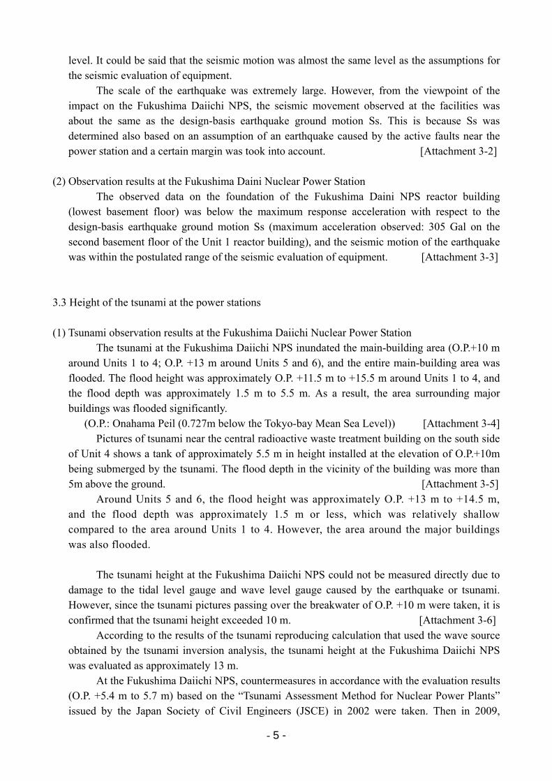
Flood height and depth at Fukushima Daiichi NPS
Area surrounding major buildings (Units 1 to 4)
Area surrounding major buildings (Units 5 and 6)
Ground Level (a) O.P. +10 m O.P.+13 m
Flood Height (b) O.P. approximately +11.5 ~ +15.5 m*1 O.P. approximately +13 ~ +14.5 m
Flood Depth (b)-(a) Approximately1.5 ~ 5.5 m Less than approximately 1.5 m
Flooded Areas Almost all of the seaside area and the surroundings of the major buildings
Note Height of the tsunami (Estimate based on the tsunami analysis): approximately. 13 m*2 Analysis result based on the assessment method introduced by the JSCE (latest): O.P.+5.4 ~ 6.1 m
*1: There were indications that the flood height reached levels of approx. O.P. +16 to 17m in some southwest areas(approximately 6 to 7m in flood depth)
*2: Near the tidal station
(2) Tsunami observation results at the Fukushima Daini Nuclear Power Station
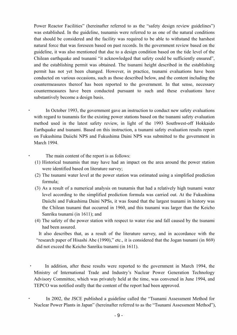
At the Fukushima Daini NPS, the flooding status around the main-building area was different from the one at the Fukushima Daiichi NPS. The entire area of the O.P. +4 m seaside area was flooded (flood height O.P. approximately +7 m). However, no signs of run-up were found that passed over the slope from the seaside area to the O.P. +12m main-building area.
Meanwhile, on the southeast side of the main-building area, the tsunami ran up intensively along the road from the seaside to the seismic isolated building. As a result, the flood depth on the south side of Unit 1 was deep. In Units 2 and 3, some amount of seawater came from the Unit 1 side. However, the flood depth around the buildings of those units was shallow, and there was almost no flooding found around the Unit 4 building. [Attachment 3-8]
The tidal level gauge and wave height gauge at the Fukushima Daini NPS were also
damaged by the earthquake or tsunami. Therefore, the tsunami height could not directly be measured. However, according to the result of the tsunami reproducing calculation, the tsunami height at the Fukushima Daini NPS was approximately 9 m. [Attachment 3-9]
Ground deformation caused by the earthquake is not reflected in the flood level and run-up height
基準面(小名浜港工事基準面) (気象庁HPに加筆)
浸水域
浸水高
遡上高
浸水深
Tsunami heightTidal gauge
station
Normal tide level (tide level when there is no tsunami)
Run-up height
Flood height Flood depth
Base level (Onahama Peil)
(Additions made to the Japan
Meteorological Agency HP)
- 7 -
At the Fukushima Daini NPS, measures were taken to maintain functions against tsunamis the height of 5.1 to 5.2 m, according to the evaluation results based on the “Tsunami Assessment Method for Nuclear Power Plants in Japan” issued by the JSCE in 2002. (The reevaluation result in 2009 using the latest submarine topography data, etc., did not imply a necessity for additional measures.) However, the tsunami on March 11 was considerably larger than this height.
As mentioned above, flooding around the major buildings of the Fukushima Daini NPS was limited. Hence damage to power facilities was small compared with that to the Fukushima Daiichi NPS, and thus, the difficulty of subsequent accident response differed greatly.
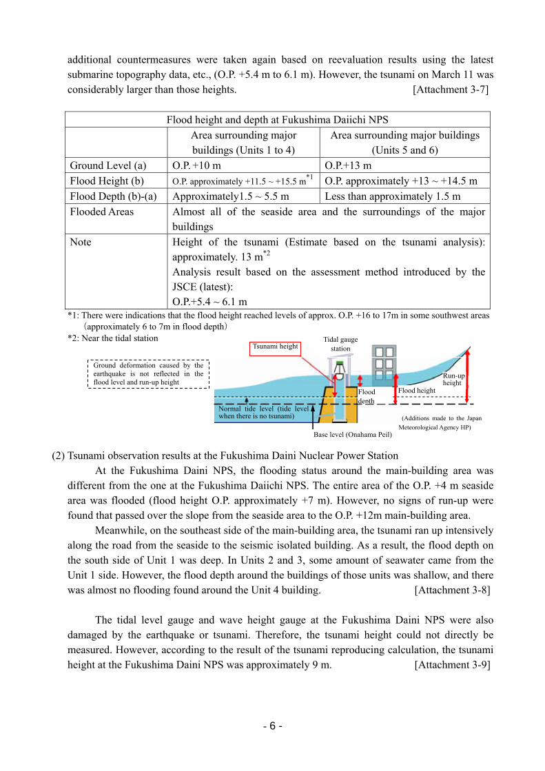
Flood height and depth at Fukushima Daini NPS
Seaside area Main building area
Ground Level (a) O.P.+4 m O.P.+12 m
Flood Height (b) O.P. approximately +7 m*1 O.P. approximately +12 ~ +14.5 m*2
Flood Depth (b)-(a) Approximately 3 m Less than approximately 2 m
Flooded Areas ・ Entire region of the seaside area was flooded
・ However, there was no run-up that passed over the slope from the seaside area to the major building area
・ Intensive run-up on the road south of the major building area (south side of Unit 1)
・ Significant flooding on the south side of Unit 1
・ Flooding around the Unit 2 building and on the south side of the Unit 3 building. However flood depth was shallow
・ No flooding around the Unit 4 buildings
Note Tsunami height (estimate according to the tsunami analysis); approximately 9 m*3 Evaluated value (latest evaluated value) according to the JSCE method: O.P.+5.1 to 5.2 m
*1: Local increase in flooding on the south surface outside the Unit 1 heat exchanger building, etc. *2: Local areas where O.P. approximately +15 to 16m from the south side of the Unit 1 building to the seismic
isolated building *3: Near the tidal station
(3) Differences in the scale of the tsunami at the Fukushima Daiichi Nuclear Power Station and the
Fukushima Daini Nuclear Power Station
The tsunami at the Fukushima Daiichi NPS (estimated tsunami height: approximately 13m) was larger than the tsunami at the Fukushima Daini NPS (estimated tsunami height: approximately 9m). The two power stations are located near one another, at a distance of approximately 12km, and the geographical features of the two regions are similar. Nevertheless, the tsunami height differed that much. The main reasons were analytically evaluated in order to understand the differences in tsunami size.
Based on the results, the main reason for the difference in tsunami scale at the two power stations is considered to be due to the fact that there were multiple tsunamis that originated from
- 8 -
regions with a large slip (wave source), envisioned off-shore of Miyagi and Fukushima prefectures, and that the overlap of those tsunami peaks happened to be large at the Fukushima Daiichi NPS and small at the Fukushima Daini NPS. [Attachment 3-10]
3.4 Tsunami evaluation
(1) Evaluation of tsunami height
・ The establishing permits for the units of the Fukushima Daiichi NPS were obtained between 1966 and 1972. At that time, there was no guideline for tsunami and the units were designed based on the known tsunami traces. Specifically, the maximum tide level that was observed at the Onahama Port (O.P. +3.122m), which was caused by the Chilean earthquake and tsunami of 1960, was established as a design basis.
・ In 1970, the “Regulatory Guide for Reviewing Safety Design of Light Water Nuclear
Fukushima Daiichi Entire facility of Fukushima Daiichi was flooded
Unit 6 Unit 5Unit 1 Unit 2 Unit 3 Unit 4
Central radioactive
waste treatment building
Seismic Isolated Building
Region flooded by the tsunami was limited
Fukushima Daini
Run-up intensively
Unit 4 Unit 3 Unit 2 Unit 1
Waste treatment building
Seismic Isolated Building
- 9 -
Power Reactor Facilities” (hereinafter referred to as the “safety design review guidelines”) was established. In the guideline, tsunamis were referred to as one of the natural conditions that should be considered and the facility was required to be able to withstand the harshest natural force that was foreseen based on past records. In the government review based on the guideline, it was also mentioned that due to a design condition based on the tide level of the Chilean earthquake and tsunami “it acknowledged that safety could be sufficiently ensured”, and the establishing permit was obtained. The tsunami height described in the establishing permit has not yet been changed. However, in practice, tsunami evaluations have been conducted on various occasions, such as those described below, and the content including the countermeasures thereof has been reported to the government. In that sense, necessary countermeasures have been conducted pursuant to such and these evaluations have substantively become a design basis.
・ In October 1993, the government gave an instruction to conduct new safety evaluations with regard to tsunamis for the existing power stations based on the tsunami safety evaluation method used in the latest safety review, in light of the 1993 Southwest-off Hokkaido Earthquake and tsunami. Based on this instruction, a tsunami safety evaluation results report on Fukushima Daiichi NPS and Fukushima Daini NPS was submitted to the government in March 1994.
・ The main content of the report is as follows: (1) Historical tsunamis that may have had an impact on the area around the power station
were identified based on literature survey; (2) The tsunami water level at the power station was estimated using a simplified prediction
formula; (3) As a result of a numerical analysis on tsunamis that had a relatively high tsunami water
level according to the simplified prediction formula was carried out. At the Fukushima Daiichi and Fukushima Daini NPSs, it was found that the largest tsunami in history was the Chilean tsunami that occurred in 1960, and this tsunami was larger than the Keicho Sanriku tsunami (in 1611); and
(4) The safety of the power station with respect to water rise and fall caused by the tsunami had been assured.
It also describes that, as a result of the literature survey, and in accordance with the “research paper of Hisashi Abe (1990),” etc., it is considered that the Jogan tsunami (in 869) did not exceed the Keicho Sanriku tsunami (in 1611).
・ In addition, after these results were reported to the government in March 1994, the Ministry of International Trade and Industry’s Nuclear Power Generation Technology Advisory Committee, which was privately held at the time, was convened in June 1994, and TEPCO was notified orally that the content of the report had been approved.
・ In 2002, the JSCE published a guideline called the “Tsunami Assessment Method for Nuclear Power Plants in Japan” (hereinafter referred to as the “Tsunami Assessment Method”),
- 10 -
which is the only guideline that describes the tsunami assessment method concretely. In this guideline, the assessment method is described, in which areas where tsunamis may be generated are defined based on historical records on tsunamis, and a wave source model for the largest tsunami in the past is set for each area, and then, taking into account the uncertainties of various parameters of the wave source model, such as fault position, strike direction, fault depth, and dip angle, many numerical simulations are conducted and the envisaged maximum tsunami is selected as a design basis. This “Tsunami Assessment Method” has since then been used as the standard method of tsunami evaluation at nuclear power stations in Japan, and it is also used in the evaluation submitted to the regulatory authority.
・ Based on the “Tsunami Assessment Method,” TEPCO calculated the tsunami water levels as follows:
Fukushima Daiichi NPS: O.P. +5.4 to 5.7 m; and Fukushima Daini NPS: O.P. +5.1 to 5.2 m.
TEPCO then implemented measures to maintain function, such as raising the electric pump motors and flooding prevention measures of the building penetration, etc. These calculation results were reported to and confirmed by the government in March 2002.
・ In June 2007, TEPCO obtained information on tsunami calculation results for disaster prevention measures of Fukushima Prefecture and confirmed that the tsunami height estimated by Fukushima Prefecture did not exceed TEPCO’s tsunami evaluation height.
・ In March 2008, TEPCO analyzed a wave source for disaster prevention measures of Ibaraki Prefecture, and confirmed that the calculated tsunami height based on the wave source did not exceed TEPCO’s tsunami evaluation height.
・ In September 2006, the “Regulatory Guide for Reviewing Seismic Design of Nuclear Power Reactor Facilities” was revised, and the government issued instructions to re-confirm seismic adequacy based on these new guidelines (hereinafter referred to as the “anti-seismic back-check”). In the anti-seismic back-check, geological surveys, etc., have already been completed, the design-basis earthquake ground motion has been established, and the seismic evaluation for major equipment has been submitted to the government as an interim report. Since tsunami evaluation is required for the final report as an event associated with the earthquake, a reevaluation was conducted for the final report based on the “Tsunami Assessment Method” in February 2009, taking into account the latest submarine topography and tide level observation data. As a result, the tsunami water level was evaluated as follows:
Fukushima Daiichi NPS: O.P. +5.4 to 6.1 m Then, pursuant to such tsunami height, countermeasures, such as the sealing of pump motors, were implemented. In addition, the reevaluation result for the Fukushima Daini NPS did not require additional countermeasures.
As described above, various efforts have been conducted in the past. However, the
tsunami on March 11 was far beyond the estimation, and as a result, preventive measures for tsunamis were not enough to prevent damage from the tsunami on March 11.
- 11 -
(2) Statements from related organizations regarding the tsunami and associated TEPCO’s responses
As described above, TEPCO has evaluated the tsunami height based on the latest established knowledge. The tsunami height has consistently been evaluated based on the JSCE’s “Tsunami Assessment Method.” since the report was submitted to the government in March 2002 up until now. In addition, when new knowledge or theories on tsunamis are proposed, TEPCO has been voluntarily conducting reviews and investigations etc., including trial calculations. As a part of this, TEPCO conducted trial calculations and tsunami deposit surveys based on the two hypotheses below, although the knowledge necessary for the tsunami evaluation such as wave source model, etc., had not yet been determined. The statements of other organizations regarding the earthquake or tsunami and associated TEPCO’s responses are described below. [Attachment 3-11, 3-12]
1) Opinion of the Headquarters for Earthquake Research Promotion In July 2002, a national institute for research and investigation known as the
Headquarters for Earthquake Research Promotion (HERP) published a long-term evaluation of earthquakes stating that “there is a possibility that an earthquake could occur anywhere along the trench off the coast from Sanriku to Bousou” (hereinafter referred to as the “opinion of the HERP”). The opinion of the HERP mentioned that there was a possibility that an earthquake of approximately M8.2 could occur even in regions where large earthquakes had not occurred in recorded history (along the trench from offshore of Fukushima to Bousou). Note that the HERP had not assumed that there would be a huge earthquake caused by combination of several focal areas like the earthquake on March 11. The HERP also had not proposed a wave source model that was indispensable for the tsunami evaluation in the area where large earthquakes had not occurred in recorded history.
The JSCE then decided to deal with the “opinion of the HERP” by a probabilistic analysis method, a discussion of which started in FY2003. This pioneering achievement that implemented tsunami evaluations based on a probabilistic approach was published as a research paper in 2005 and 2007.
The probabilistic analysis takes into account opinions of experts weighing in on the deliberation, and it results in the variation of the evaluation results. Therefore, it has become an issue of how to use the evaluated results. TEPCO had been paying close attention to the status of the discussion in the JSCE. Also, TEPCO conducted a hypothetical analysis of a probabilistic tsunami hazard for the Fukushima site as one example in order to identify the applicability of the probabilistic tsunami hazard analysis methodology under development and to improve it,* based on the result of discussions in the JSCE between 2003 and 2005. TEPCO organized the relationship between the tsunami height and annual probability of exceedance and submitted a research paper in 2006.
*: The tsunami probabilistic evaluation method has continuously been discussed in the JSCE through FY2006-FY2008 (the wave source of the Jogan tsunami mentioned later was also dealt with in the discussion on a probabilistic manner). However, the probabilistic method has not been used as a tsunami evaluation method, even at the current stage, and it is still an experimental stage.
- 12 -
Furthermore, in 2008, TEPCO conducted another hypothetical trial calculation as a reference for internal discussion on how to cope with the opinion of the HERP that “there is a possibility that an earthquake could occur anywhere along the trench from off-shore of Sanriku to Bousou” in the deterministic anti-seismic back-check.
In the region along the Japan Trench off-shore of Fukushima, there had been no large earthquakes in the past. Therefore a wave source model required to implement a tsunami evaluation had not been established. Consequently, the tsunami water level in the event that the wave source model of the Meiji Sanriku-oki Earthquake (M8.3) that would be most severe for the Fukushima site was brought about along the trench off-shore Fukushima was estimated, although it does not match the earthquake size (M8.2) presented by the HERP. The result of this trial calculation showed a maximum tsunami height of O.P. +8.4 to 10.2 m at the front of the Fukushima Daiichi NPS intake point.
Regarding the opinion of the HERP, TEPCO requested the JSCE to discuss the formulation of a specific wave source model in order to conduct tsunami evaluations based on the opinion of the HERP because of the following reasons: 1) The JSCE’s “Tsunami Assessment Method,” which is used by operators of electric
utilities as a guideline for tsunami assessment, does not take into account the occurrence of a tsunami along the trench off-shore Fukushima; and
2) A wave source model necessary for tsunami evaluation had not been determined. The Central Disaster Prevention Council set up a “Special Investigation Committee
on the Subduction Zone Earthquake around Japan Trench and Chishima Trench” in October 2003, and compiled a report regarding the envisioned damage in January 2006 after discussion for more than 2 years. According to the report, the earthquakes that repeatedly occurred in the past would be considered for disaster prevention measures. With respect to the area along the Japan Trench, although the possibility of an offshore Sanriku earthquake was assumed, the opinion of the HERP in 2002 concerning the area along the trench from off-shore of Fukushima to Bousou was not reflected.
2) Jogan Tsunami With regard to the Jogan tsunami, Dr. Satake of the National Institute of Advanced
Industrial Science and Technology (at the time) provided TEPCO with a research paper regarding the Jogan tsunami being prepared for submission in October 2008. In the paper, the genesis location and scale of the Jogan tsunami in 869 was estimated based on the results of the tsunami deposit survey in the Sendai Plain and Ishinomaki Plain. Two wave source models were proposed but not established, and the necessity of conducting a tsunami deposit survey in the coastal area of Fukushima Prefecture, etc., for their establishment was indicated.
Since Dr. Satake’s paper proposed wave source models, although they were not
verified, TEPCO conducted a trial calculation using the two models proposed in the paper in December 2008. The result of the trial calculation showed a tsunami height of O.P. +7.8 m to 8.9 m (O.P. +7.8 m to 9.2 m, if a different accounting method for high tide is used) in front of the Fukushima Daiichi and Fukushima Daini NPS intake points.
- 13 -
In April 2009, the research paper was officially published. Although the paper described the wave source models of the Jogan tsunami as mentioned above, these wave source models were based on the results of the tsunami deposit survey in the Sendai Plain and Ishinomaki Plain, and the location and scale of the tsunami, etc., remained unestablished. A tsunami deposit survey in the coastal area of Fukushima Prefecture etc., was required for their establishment.
In June 2009, a discussion regarding the establishment of a specific wave source model for tsunami evaluation was requested to the JSCE together with the discussion on the opinion of the HERP.
In order to investigate the presence of tsunami impacts on the Fukushima Daiichi and Fukushima Daini NPSs due to the Jogan earthquake, TEPCO conducted a tsunami deposit survey along the Pacific coast of Fukushima Prefecture. As a result of the surveys, tsunami deposits by the Jogan tsunami were confirmed to an altitude of about 4m in the northern area of Fukushima Prefecture, while no tsunami deposits were found in the southern area (Tomioka to Iwaki). As inconsistencies between the investigation results and the proposed wave source model that was used for the trial calculation were found, TEPCO considered that it was necessary to conduct further investigation and research in order to determine the wave source of the Jogan tsunami.
TEPCO submitted a research paper on the results of the tsunami deposit survey in
January 2011, and a presentation was given at the 2011 Japan Geoscience Union Meeting in May 2011.
The genesis location and scale, etc.(wave source model) of the Jogan tsunami has still not been established even now.
3) Summary
TEPCO conducted trial calculations, etc., internally regarding the “opinion of the
HERP” (published as a long-term evaluation in 2002). However, due to the following reasons, the trial calculations were based on hypotheses that were not supported by specific evidence:
The “Tsunami Assessment Method” of the JSCE, which is used by operators of electric utilities as a guideline for tsunami assessment, does not take into account tsunami occurrences along the trench off-shore Fukushima; and
A specific wave source model necessary for tsunami evaluation has not been determined.
Later, without specific evidence, it was decided that the operators of electric utilities would jointly conduct research as a part of the activities to establish the wave source, and after the discussion with experts on the research policies and procedure of the research, a discussion on the establishment of a wave source model was requested to the JSCE in June 2009*.
Furthermore, with regards to the Jogan tsunami, it was considered that further reviews would be necessary in order to establish the wave source model of the Jogan
- 14 -
tsunami based on the results of the tsunami deposit surveys, etc., and in order to clarify how nuclear power stations should handle the Jogan tsunami in terms of the tsunami assessment it was also requested to the JSCE that experts at the JSCE discuss this issue, together with the opinion of the HERP.*
*: The Tsunami Evaluation Subcommittee, the Nuclear Civil Engineering Committee, JSCE was planning to revise the “Tsunami Assessment Method” of February 2002 based on new findings, etc., since its publication after the discussions regarding a wide range of areas with the following objectives between FY2009 and FY2011: (1) Establishing a wave source model to be used in the determinism of the area near Japan (along the
Pacific plate boundary, Nankai Trough, and the eastern margin of the Japan Sea) and foreign coastlines;
(2) Sophistication of the numerical calculation method; (3) Consideration of how to account for uncertainties (including review on probabilistic approach): and (4) Establishing evaluation methods of wave force and sand movement associated with tsunamis, etc. The above-mentioned “opinion of the HERP” and the Jogan tsunami wave source model were considered for (1) and were under discussion.
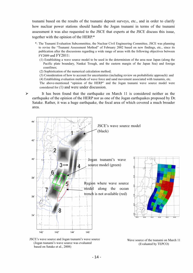
It has been found that the earthquake on March 11 is considered neither as the earthquake of the opinion of the HERP nor as one of the Jogan earthquakes proposed by Dr. Satake. Rather, it was a huge earthquake, the focal area of which covered a much broader area.
JSCE’s wave source and Jogan tsunami’s wave source
(Jogan tsunami’s wave source was evaluated based on Satake et al., 2008)
Jogan tsunami’s wave source model (green)
Region where wave source model along the ocean trench is not available (red)
JSCE’s wave source model (black)
Wave source of the tsunami on March 11(Evaluated by TEPCO)

- 15 -
(3) Site elevation of buildings and installed locations of equipment
・ The major buildings of the Fukushima Daiichi NPS are located at an elevation of O.P. +10 m for Units 1 to 4, which suffered major damage, and at an elevation of O.P.+13 m for Unit 5 and 6. When obtaining the establishing permit, the Chilean tsunami had been envisioned as the greatest tsunami in history, and the tsunami height at that time was O.P. +3.1 m. At present, the tsunami height of O.P.+6.1 m, that was evaluated based on the “Tsunami Assessment Method” of the JSCE, is used for the design purpose. It was recognized that there would not be any tsunami that could run up to the level of the buildings.
・ With regard to the relationship between the design-basis tsunami height and the major building area, a comparison of the relationship between the design-basis tsunami height, etc., and the site elevation of major buildings was conducted based on data, described in the accident report submitted by the Japanese government to the IAEA Ministerial Conference in June 2011, of the Tohoku Electric Power Company’s Onagawa NPS, Japan Atomic Power Company’s Tokai Daini Power Station, which are located on the Pacific coast. .
・ The results showed that the elevation of major buildings of the Fukushima Daiichi NPS was not necessarily lower compared with the design-basis tsunami height calculated based on the same JSCE’s guideline, “Tsunami Assessment Method.” [Attachment 3-13]
Tsunami height (m)
Name
(A) elevation
of major
buildings (m)Establishing
permit (B) JSCE (C)
(A-B)
A
(A-C)
A
Fukushima Daiichi NPS +10.0 +3.122 +6.1 68% 39%
Japan Atomic Power Company
Tokai Daini Power Station +8.9
No description
+5.8 - 34%
Tohoku Electric Power Company
Onagawa NPS +14.8 +9.1 +13.6 38% 8%
・ Regarding the structure of the reactor buildings at the Fukushima Daiichi and Fukushima Daini NPSs, Fukushima Daiichi Unit 6 and Fukushima Daini Units 1 to 4 have combination structure-type reactor buildings with annexes attached to the outer side of their reactor blocks. On the other hand, the Fukushima Daiichi Units 1 to 5 have stand-alone type reactor blocks without annexes.
・ At Fukushima Daiichi Units 1 to 5, where the reactor buildings of which do not have annexes, since EDGs (installed from the beginning) are driven by diesel engines that use light oil as fuel, the EDGs were installed not in the reactor buildings that require air-tightness, but in the basement of the turbine buildings.
・ Investigation on the plants revealed that EDGs are not located inside the reactor buildings that require air-tightness. U.S. plants that were under construction when Fukushima Daiichi Unit 1 was designed were designed to plant-specific seismic criteria as early as 1969,
- 16 -
using the existing subsurface conditions for the individual plants. U.S. designs are unique to the site soil conditions, supported by rock or a unique subsurface formation, or on spread-footer foundations. Hence, most of the buildings in which EDGs are installed did not require foundations built on base rock. In comparison, many buildings in Japanese NPSs have basement floors due to the necessity of being built on the base rock layer for seismic reasons.
Due to such differences, EDGs were installed on the foundation (the lowest floor) in Japan in consideration of the large components’ seismic adequacy and vibrations.
・ On the other hand, at Fukushima Daiichi Unit 6 and Fukushima Daini Units 1 to 4, which have combination structure-type reactor buildings, EDGs were installed not in the reactor buildings that requires air-tightness, but in the basement of the annexes outside.
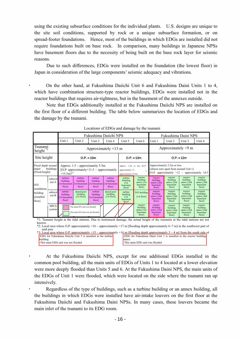
Note that EDGs additionally installed at the Fukushima Daiichi NPS are installed on the first floor of a different building. The table below summarizes the location of EDGs and the damage by the tsunami.
・ At the Fukushima Daiichi NPS, except for one additional EDGs installed in the common pool building, all the main units of EDGs of Units 1 to 4 located at a lower elevation were more deeply flooded than Units 5 and 6. At the Fukushima Daini NPS, the main units of the EDGs of Unit 1 were flooded, which were located on the side where the tsunami ran up intensively.
・ Regardless of the type of buildings, such as a turbine building or an annex building, all the buildings in which EDGs were installed have air-intake louvers on the first floor at the Fukushima Daiichi and Fukushima Daini NPSs. In many cases, these louvers became the main inlet of the tsunami to its EDG room.
非常用D/Gの設置場所と津波被害の状況
原子炉建屋
付属棟
[地下2階]
原子炉建屋
付属棟
[地下2階]
原子炉建屋
付属棟
[地下2階]
原子炉建屋
付属棟
[地下2階]
原子炉建屋
付属棟
[地下1階]
HPCS
系
原子炉建屋
付属棟
[地下2階]
原子炉建屋
付属棟
[地下2階]
原子炉建屋
付属棟
[地下2階]
原子炉建屋
付属棟
[地下2階]
D/G建屋
[1階]タービン建屋
[地下1階]
共用プール
建屋
[1階]
タービン建屋
[地下1階]
共用プール
建屋
[1階]
タービン建屋
[地下1階]B系
原子炉建屋
付属棟
[地下2階]
原子炉建屋
付属棟
[地下2階]
原子炉建屋
付属棟
[地下2階]
原子炉建屋
付属棟
[地下2階]
原子炉建屋
付属棟
[地下1階]
タービン建屋
[地下1階]タービン建屋
[地下1階]タービン建屋
[地下1階]タービン建屋
[地下1階]タービン建屋
[地下1階]A系
D/G
設置建屋
[設置階]
約2.5m以下(1号機周囲以外はほとんどゼロ)[O.P.約+12~約14.5m]※3
約1.5m以下[O.P.約+13~約+14.5m]
約1.5~約5.5m[O.P.約+11.5~約+15.5m]※2
主要建屋周り
浸水深[浸水高]
O.P.+12mO.P.+13mO.P.+10m敷地高さ
約+9m約+13m津波高さ※1
4号機3号機2号機1号機6号機5号機4号機3号機2号機1号機
福島第二原子力発電所福島第一原子力発電所
原子炉建屋
付属棟
[地下2階]
原子炉建屋
付属棟
[地下2階]
原子炉建屋
付属棟
[地下2階]
原子炉建屋
付属棟
[地下2階]
原子炉建屋
付属棟
[地下1階]
HPCS
系
原子炉建屋
付属棟
[地下2階]
原子炉建屋
付属棟
[地下2階]
原子炉建屋
付属棟
[地下2階]
原子炉建屋
付属棟
[地下2階]
D/G建屋
[1階]タービン建屋
[地下1階]
共用プール
建屋
[1階]
タービン建屋
[地下1階]
共用プール
建屋
[1階]
タービン建屋
[地下1階]B系
原子炉建屋
付属棟
[地下2階]
原子炉建屋
付属棟
[地下2階]
原子炉建屋
付属棟
[地下2階]
原子炉建屋
付属棟
[地下2階]
原子炉建屋
付属棟
[地下1階]
タービン建屋
[地下1階]タービン建屋
[地下1階]タービン建屋
[地下1階]タービン建屋
[地下1階]タービン建屋
[地下1階]A系
D/G
設置建屋
[設置階]
約2.5m以下(1号機周囲以外はほとんどゼロ)[O.P.約+12~約14.5m]※3
約1.5m以下[O.P.約+13~約+14.5m]
約1.5~約5.5m[O.P.約+11.5~約+15.5m]※2
主要建屋周り
浸水深[浸水高]
O.P.+12mO.P.+13mO.P.+10m敷地高さ
約+9m約+13m津波高さ※1
4号機3号機2号機1号機6号機5号機4号機3号機2号機1号機
福島第二原子力発電所福島第一原子力発電所
※1 両発電所の検潮所設置位置における津波高さ。計器損傷のため、検潮所における実際の津波高さは把握できていない。※2 当該エリア南西部では局所的にO.P.約+16~約+17m[浸水深 約6~7m]※3 1号機建屋南側から免震重要棟にかけて局所的にO.P.約+15~約+16m[浸水深 約3~4m]
・福島第一5号機のD/Gはタービン建屋に設置・当該D/G本体は被水していない
・福島第二1号機のD/Gは原子炉建屋付属棟に設置・当該D/G本体は被水している
D/G本体が被水した
D/G本体が被水していない
D/G本体が被水した
D/G本体が被水していない
D/G本体が被水した
D/G本体が被水していない
turbine building
[1st basement floor]
turbine building
[1st basement
floor]
shared pool building
[1st floor]
reactor building
annex [1st basement
floor]
D/G building
[1st floor]
Tsunami height *1
Site height
Flood depth around major buildings [Flood height]
D/G
installation
building
[installed
floor]
Approx. 1.5 ~ approximately 5.5m [O.P. approximately+11.5 ~ approximately +15.5m]*2
Approximately 2.5m or less (almost zero apart from around Unit 1) [O.P. approximately +12 ~ approximately 14.5
Approx. 1.5m or less [O.P.
approximately+13 ~
approximately 14.5m]
Approximately +13 m Approximately +9 m
Locations of EDGs and damage by the tsunami
Fukushima Daiichi NPS Fukushima Daini NPS Unit 2 Unit 3 Unit 4 Unit 5 Unit 6 Unit 1 Unit 2 Unit 3 Unit 4
subsystem-A
The main D/G unit was flooded
*1: Tsunami height at the tidal stations. Due to instrument damage, the actual height of the tsunamis at the tidal stations are not known. *2: Local area where O.P. approximately +16 ~ approximately +17 m [flooding depth approximately 6~7 m] in the southwest part of
said area *3: Local area where O.P. approximately +15 ~ approximately +16 m [flooding depth approximately 3 ~ 4 m] from the south side of
Unit 1
subsystem-B
HPCS system
turbine building
[1st basement floor]
turbine building
[1st basement floor]
turbine building
[1st basement floor]
turbine building
[1st basement floor]
turbine building
[1st basement floor]
turbine building
[1st basement
floor]
shared pool building
[1st floor]
reactor building
annex [2nd basement
floor]
reactor building
annex [2nd basement
floor]
reactor building
annex [2nd basement
floor]
reactor building
annex [2nd basement
floor]
reactor building
annex [2nd basement
floor]
reactor building
annex [2nd basement
floor]
reactor building
annex [2nd basement
floor]
reactor building
annex [2nd basement
floor]
reactor building
annex [2nd basement
floor]
reactor building
annex [1st basement
floor]
reactor building
annex [2nd basement
floor]
reactor building
annex [2nd basement
floor]
reactor building
annex [2nd basement
floor]
The main D/G unit was not flooded
-EDG for Fukushima Daiichi Unit 5 is installed in the turbine building -This main EDG unit was not flooded
-EDG for Fukushima Daini Unit 1 is installed in the reactor buildingannex -This main EDG unit was flooded

- 17 -
・ Based on the above, it is considered that once the area around the building is flooded, the EDG itself would be flooded due to the physical relationship between the openings that serve as flooding routes, such as the louvers, and the flooding depth, regardless of the type of building or the floor location where the EDG is installed.
- 18 -
4 Preparations for Accidents in the Power Station 4.1 Regulations
The “Act on the Regulation of Nuclear Source Material, Nuclear Fuel Material and Reactors (hereinafter referred to as “Reactor Regulation Act”)” defines all relevant permits and procedural standards, including the reactor establishing permit. In accordance with this Act, application documents of the basic design of a nuclear reactor for power generation are required to obtain approval from the Minister of Economy, Trade and Industry (METI).
METI examines the application documents of the basic design of the nuclear facility as to whether the application meets the permit standards prescribed in the Reactor Regulation Act. Thereafter, the Nuclear Safety Commission of Japan (NSC) is consulted on the result and it also conducts an examination (double-checking). These examinations check the compatibility of the guidelines, such as the safety design review guidelines submitted by the NSC.
As for the operation and maintenance of power plants, plant operators define a standard called “Technical Standards for Nuclear Reactor Facility” (hereinafter referred to as “Technical Standards”) regarding facility maintenance and other activities. The Technical Standards are required to be approved by the Minister of METI. Furthermore, the status of compliance is confirmed through safety inspections or regular inspections conducted by the Minister of METI.
The Electricity Business Act defines procedures for approval of construction plans,
pre-operation inspections, periodical inspections, etc. Prior to the construction, the construction plan is required to be approved by the Minister of METI. Fuel design installed in the reactor also required to be approved. Inspections such as pre-operation inspections, nuclear fuel inspections, periodical inspections after starting operation are required to be conducted by either the Minister of METI or Japan Nuclear Energy Safety Organization (JNES), which was authorized by the Minister of METI.
4.2 Facility design
When designing nuclear power generation equipment, assuming that human error and mechanical failure will occur, multiple, diverse, and independent emergency system cooling equipment, etc., were installed in preparation for accidents caused by a single equipment failure.
Furthermore, for vital functions, such as reactor scram, they are designed based on the philosophy of operating on the safe side in case of failure. [Attachment 4-1]
[Attachment 4-2] shows the status for major equipment related to the “cooling down” function of
a nuclear reactor and “confining inside” (containment vessel) function of the radioactive materials. Since these functions are vital to accident management, equipment is installed that
consists of multiple systems and diverse functions that are able to operate independently in the case of an accident, even if some part of those functions fails.
Based on this concept, application documents of basic design of a nuclear facility are approved if the design of the structures, systems, etc., is appropriate to prevent nuclear disaster.
- 19 -
4.3 Updates on new findings [Attachment 4-3]
At the operation and maintenance stage, check-ups for facilities conditions and operability are routinely performed based on technical specifications approved by the government. This is conducted in order to ensure that the equipment is premised on the design or the establishing permit and that it maintains its necessary functions.
In addition to this, new knowledge, including operating experience from TEPCO’s plants and those of other companies, has been actively implemented, even after construction of the plant. This is done from the standpoint of facilities and operation, as part of the efforts to reduce the risk of nuclear disaster. Examples include:
・ Performing upgrades of equipment that directly affects plant “cooling down” and “confining inside” functions. These include: stress corrosion cracking measures for the recirculation system (PLR) piping connected to the RPV; installation work for new underground seawater system piping within concrete ducts as a replacement of piping directly laid in the ground; and enlargement of strainers to prevent clogging of the emergency core cooling system (ECCS) suction strainer. The last one was taken as a countermeasure from an example of noncompliance in an overseas plant.
・ Performing upgrades of equipment in order to improve the overall plant reliability. These include: core shroud replacement work as a measure for corrosion cracking of core structures; feedwater heater replacement for preventing abrasion and erosion; and feedwater control equipment replacement as a part of aging degradation measures.
・ Implementing water tightness measures to ensure that underground vital equipment does not lose its function due to flooding caused by a rupture of piping inside buildings and other reasons.
- Installing water barriers at the stair openings in reactor buildings - Improving water tightness of entrance doors for the residual heat removal system (RHR)
room and other rooms that are located on the basement floor of reactor buildings - Increasing water barrier height for emergency electrical equipment rooms - Improving water tightness of entrance doors for EDG rooms, etc.
As stated above, with regard to the flooding from outside of the buildings due to tsunami, since the site elevation of the buildings was higher than the predicted tsunami height, the run-up of the tsunami was not considered to affect equipment, and no special measures against tsunamis were taken for equipment inside the building.
・ Lessons learned from the Niigata-Chuetsu-Oki Earthquake were also reflected at the stations. These reflected countermeasures showed good performance during the Fukushima accident. In particular, the seismic isolated building (installation of anti-seismic structure for the emergency response room) maintained its function as the emergency response center (ERC). Newly allocated fire engines were used as reactor injection pumps although they were not intended as the original purpose.
As stated above, continuous efforts have been put into practice in order to reduce the risk
of nuclear disasters by learning from TEPCO’s own and other plant operator’s operating
- 20 -
experiences and from other lessons. In the next section, details of accident management (AM) measure are described.
Although these efforts were voluntarily made by operators of electric utilities, they were actually begun pursuant to the instruction of the government. The details of these measures were reported to and confirmed by the government as appropriate, and these measures were put into practice together with the government. However, the prepared countermeasures could not prevent the expansion of this accident.
4.4 Preparation for accident management [Attachment 4-4]
As a part of activities for reducing the risk of nuclear disasters, the NSC extracted 52 lessons learned from the Three Mile Island (TMI) accident that should be reflected in the nuclear safety assurance measures in Japan. The necessary response was put into practice by both the government and utilities. The accident at Chernobyl Nuclear Power Plant Unit 4 in 1986 resulted in worldwide interest in severe accident measures, since both the TMI and Chernobyl accidents were severe accidents.
This movement also led to the establishing of the Common Issue Committee by the NSC, and the Committee started discussions on how to implement countermeasures for severe accidents from the position of safety. The Committee submitted an interim report in February 1990, and then an official report to the NSC in February 1992. These reports proactively stated the role of the government that should be implemented. In the report, the committee requested the NSC to identify basic concepts of the properties of the utilities’ preparation, its positioning, and the responsibilities of both utilities and the government in order to clearly indicate the future direction and the framework. In addition, the committee pointed out the necessity to gain consensus on the role of the government for the preparation of AM measures.
Following this report, the NSC submitted the “Accident Management for Severe Accidents at Light Water Power Reactor Installations” in May 1992. Per the request for the AM preparation from the Ministry of MITI based on this guideline in July 1992, utilities prepared AM measures in order to enhance the multiple systems and diverse functions so that the “shutting down,” “cooling down” and “confinement” functions would not be lost even in the event of multiple failures during the period between 1994 and 2002.
- 21 -
Basic approach to AM preparation (Instruction by NSC, etc.)
・ The safety of reactor facilities in Japan is sufficiently ensured by current safety regulations
by implementing, under current safety regulations, strict safety measures in the design,
construction and operation stages, based on the defense-in-depth concept to (1) prevent the
occurrence of abnormal events, (2) prevent an abnormal event from spreading and developing
into an accident, and (3) prevent the abnormal release of fission products.
・ The possibility of severe accidents is sufficiently low due to these measures, to the extent
that such accidents could not occur from an engineering viewpoint, and thus, the risk from
reactor facilities is considered to be sufficiently low.
・ The development of accident management measures is significant in further reducing the
risk, which is already low.
・ The Commission believes that effective accident management should be developed by
licensees on a voluntary basis and that its proper implementation in the event of an emergency
should be strongly recommended.
・ It should be recommended or expected to implement accident management as long as the
implementation is possible without significantly changing the components of reactor facilities
and that it reduces the risks effectively.
As a part of the AM measures, several modifications for facilities were implemented in
order to maximize the potential capabilities of existing equipment. Specific modification of the equipment is described below.
・ Installation of connecting piping and motor-operated valves were installed in order to inject water into the reactors from the main control room (MCR) utilizing the existing make up water condensate system (MUWC) and the FP line via the core spray system for Fukushima Daiichi Unit 1, or via the RHR for Fukushima Daiichi Units 2 to 6 and Fukushima Daini Units 1 to 4. (alternate water injection)
・ In order to deal with excessive Primary Containment Vessel (PCV) pressure due to failed PCV heat removal capability, a new line that is able to withstand high pressure was installed and connected to the existing line. This allowed an operator to be able to release pressure inside the PCV from the MCR. (PCV hardened vent)
・ In order to respond to the loss of EDGs and DC power sources, alternate power source cross-ties were installed to adjacent units.
[Attachment 4-5]
On the operation side, in addition to preparations in response to multiple failures, the existing manuals were revised and the operational guidelines, such as severe accident operating procedures (SOP), were established as well in order to ensure accurate AM implementation.
In addition, taking into account the necessity of a proper understanding of AM and preparation, training for operators and supporting organization personnel had been periodically scheduled and implemented. Preparations of these equipment, response, and procedural manuals, etc. (preparation for AM measures) were undertaken by operators of electric utilities together with the government. The preparations were put into practice after their contents were reported to and confirmed by the government as appropriate.
- 22 -
As stated above, the “shutdown,” “cooling,” and “containment” functions needed for accident response as well as their power source systems have been strengthened so that they have multiplicity, diversity and independence, and they will not lose their functions at the time of an accident to the maximum extent, even though an accident exceeding the postulated incidents for design occurs. Furthermore, in order to respond to an accident appropriately with the aid of these facilities, a framework, procedural manuals, etc., have been prepared, and training has been conducted.
However, the accident on March 11 was beyond the postulated conditions. 4.5 Accident management measures and the Fukushima accident
As stated above, certain accident response systems and procedures manuals had been prepared for an accident beyond the design basis. However, since, in this accident, the tsunami impact was far beyond the previous estimation and resulted in a situation on the site far beyond the originally estimated accident management conditions, almost all equipment and power sources expected to be activated in case of accidents lost their functions.
For example, from the standpoint of reactor cooling, in addition to regular feedwater lines,
various emergency water injection means, including reactor core isolation cooling system (RCIC), were installed. Furthermore, preparation was also made for allowing water injection into reactor by various ways via control rod drive hydraulic pressure systems, condensate makeup water systems, and FP lines, etc., none of which were originally intended to be used for reactor water injection.
It was planned that water injection into the reactor would be conducted by utilizing either one of such measures. However, in the accident, since power supply was lost due to the impact of the tsunami, motor-driven reactor water injection equipment lost their functions. In addition, the initially functioning steam-driven RCIC and other systems also gradually lost their function due to several reasons, such as a loss of DC power supply necessary for controlling the system, and ultimately all these measures for water injection into reactor were lost.
On the other hands, in the response to the accident, fire engines, which had been deployed
as a lesson learned from the Chuetsu-oki earthquake—although this was not originally intended as alternative water injection method in AM measures—were used for water injection into the reactor. In this process, for the water injection route into the reactor cooling, an FP line was used that had been installed as part of AM measures. This response came from a flexible applied action based on the knowledge gained via preparation of procedures manuals and training, etc., as a part of AM measure preparation. However, these efforts could not catch up with the progression of the accident accordingly, and could not prevent the reactor core from being damaged.
From the perspective of power supply, multiple EDGs were installed for each unit, assuming the loss of power supply through the off-site transmission lines. Furthermore, the safety design review guideline requires safe reactor shutdown in case of a short-term (30 min.) total loss of AC power sources due to EDG malfunction, and in such case, water injection into
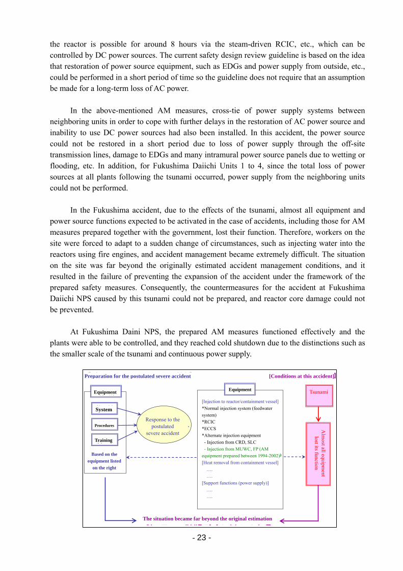
- 23 -
the reactor is possible for around 8 hours via the steam-driven RCIC, etc., which can be controlled by DC power sources. The current safety design review guideline is based on the idea that restoration of power source equipment, such as EDGs and power supply from outside, etc., could be performed in a short period of time so the guideline does not require that an assumption be made for a long-term loss of AC power.
In the above-mentioned AM measures, cross-tie of power supply systems between
neighboring units in order to cope with further delays in the restoration of AC power source and inability to use DC power sources had also been installed. In this accident, the power source could not be restored in a short period due to loss of power supply through the off-site transmission lines, damage to EDGs and many intramural power source panels due to wetting or flooding, etc. In addition, for Fukushima Daiichi Units 1 to 4, since the total loss of power sources at all plants following the tsunami occurred, power supply from the neighboring units could not be performed.
In the Fukushima accident, due to the effects of the tsunami, almost all equipment and
power source functions expected to be activated in the case of accidents, including those for AM measures prepared together with the government, lost their function. Therefore, workers on the site were forced to adapt to a sudden change of circumstances, such as injecting water into the reactors using fire engines, and accident management became extremely difficult. The situation on the site was far beyond the originally estimated accident management conditions, and it resulted in the failure of preventing the expansion of the accident under the framework of the prepared safety measures. Consequently, the countermeasures for the accident at Fukushima Daiichi NPS caused by this tsunami could not be prepared, and reactor core damage could not be prevented.
At Fukushima Daini NPS, the prepared AM measures functioned effectively and the
plants were able to be controlled, and they reached cold shutdown due to the distinctions such as the smaller scale of the tsunami and continuous power supply.
想定していたシビアアクシデントへの対応
【原子炉/格納容器への注水】
・通常注水系(給復水系)
・原子炉隔離時冷却系(RCIC)
・非常用炉心冷却系
・代替注水設備
- CRD、SLCからの注水
- MUWC、FPからの注水(H6~14整備のAM設備)
【格納容器からの除熱】・ ・・・・・・・・・
・ ・・・・・・・・・
【サポート機能(電源供給)】・ ・・・・・・・・・
・ ・・・・・・・・・
体 制
手順書
訓 練
右記設備を
前提
ほぼ全ての機器が
機能喪失
取り組みの前提を大きく外れる事態
【想定していたシビアアクシデントへの対応】 【今回の事態】
今回の
津波
設 備設 備
Preparation for the postulated severe accident
EquipmentEquipment
System
Procedures
Training
The situation became far beyond the original estimation
Based on the
equipment listed
on the right
Response to the postulated
severe accident
[Conditions at this accident]
Tsunami
Alm
ost all equipment
lost its function
[Injection to reactor/containment vessel]
*Normal injection system (feedwater
system)
*RCIC
*ECCS
*Alternate injection equipment
- Injection from CRD, SLC
- Injection from MUWC, FP (AM
equipment prepared between 1994-2002)
[Heat removal from containment vessel]
….
….
[Support functions (power supply)]
….
….
- 24 -
5 Preparation for Emergency Response
5.1 Preparation for emergency response to a nuclear disaster
The Act on Special Measures Concerning Nuclear Emergency Preparedness (Act No. 156 of 1999, hereinafter referred to as “Nuclear Emergency Act”) aims to enhance nuclear emergency measures. This act mandates the selection of nuclear disaster prevention managers and the establishment of nuclear disaster prevention organizations at each nuclear facility, as an organization to prevent the occurrence or spread of nuclear disaster.
In the Nuclear Emergency Act, it is also stipulated that a nuclear operator disaster
prevention business plan (hereinafter referred to as “disaster prevention business plan”) be prepared regarding the specific plan on the establishment and operation of the nuclear disaster prevention organization.
In the disaster prevention business plan, a level 1 state of emergency shall be declared
upon the occurrence of a specified event outlined in Article 10 of the Nuclear Emergency Act. The ERC shall be set up at the station and the headquarters in accordance with this order. [Attachment 5-1] shows the nuclear disaster prevention organization for Fukushima Daiichi NPS and the headquarters upon declaration of the level 1 state of emergency.
Once the ERC is set up, the nuclear disaster prevention manager (site superintendent) will act as a director of the ERC at the power station in accordance with the Nuclear Emergency Act. According to the disaster prevention business plan, the director is required to “proactively perform activities for the nuclear disaster based on the director’s authority. When immediate action is necessary, he is allowed to act flexibly even if it is beyond his authority.”
The ERC at the headquarters is headed by the headquarters director (President) whose role
is to support the countermeasures on the site. The ERCs in the headquarters and the power station are expected to “maintain mutual and frequent communication.”
In the Fukushima accident, the response centers were continuously connected via
teleconferencing systems, even immediately after the earthquake, and they were attempting information sharing on a real-time basis.
5.2 Response during the accident
During the Tohoku-Chihou-Taiheiyo-Oki Earthquake that occurred at 14:46 on March 11,
2011, seismic motions exceeding intensity 6-lower on the Japanese scale were measured in Fukushima Prefecture and locations within TEPCO's service area, including Ibaraki and Tochigi Prefectures. Then, a level 3 state of emergency, which is defined by the TEPCO's regulations on natural disasters such as earthquakes, was automatically declared for the headquarters and relevant sites. The Fukushima Daiichi and Daini NPSs were immediately connected to the headquarters via teleconferencing system at this point, performing coordinated post-earthquake
- 25 -
response. [Attachment 5-2] shows the level 3 state of emergency at the headquarters and at Fukushima Daiichi NPS.
At the Fukushima Daiichi NPS, workers evacuated to the main office parking lot, the designated evacuation area. After inquiring about workers’ safety, approximately 400 workers, including emergency disaster response team members and other workers, government nuclear safety inspectors, and workers from affiliated companies, entered the seismic isolated building and began their response.
At the headquarters, Emergency disaster response team members were called via general P.A. and automated callout systems. Approximately 200 employees gathered in the emergency disaster response measure office and began their activities.
Due to the tsunami following the earthquake, all AC power sources were lost at
Fukushima Daiichi NPS Units 1 to 3. At 15:42, it was decided that the status meets the conditions prescribed in Article 10 of the Nuclear Emergency Act. A notification in accordance with this Act was made alongside a declaration of a level 1 state of emergency for nuclear disasters, which was prescribed in the disaster prevention business plan.
Since the level 3 state of emergency had already been declared following the earthquake, the disaster response headquarters was already established. After the declaration of the level 1 state of emergency for nuclear disasters, the disaster response headquarters and nuclear emergency response headquarters were merged into one joint emergency response headquarters.
At 16:36, reactor water levels could not be confirmed for Fukushima Daiichi Units 1 and
2. Since the injection status were also unclear, it was determined that a specified event (failure of emergency core cooling function) prescribed in Article 15 of the Nuclear Emergency Act had occurred. The emergency state was immediately elevated to a level 2 state of emergency for nuclear disasters, in accordance with the disaster prevention business plan.
Under the Nuclear Emergency Act, the Prime Minister must issue a declaration of a nuclear emergency situation if a specified event outlined in Article 15 occurs. The Prime Minister also has to set up both a nuclear disaster response headquarters and a nuclear disaster site response headquarters.
In the Fukushima Accident, a declaration of nuclear emergency situation was issued at 19:03. At the same time, the nuclear disaster response headquarters was set up at the cabinet office. Also, the nuclear disaster site response headquarters was set up at the “off-site center,” which was established as a base for emergency response near the power station.
The off-site center is a key location, where the actual disaster response measures are performed near the power station. For this reason, the disaster prevention business plan stipulates that TEPCO has to dispatch staff members to the off-site center. However, the nuclear disaster site response headquarters at the off-site center could not perform initial activities during this accident due to the reasons such as power outages. This caused delays in dispatching workers from the ERC at Fukushima Daiichi. Upon having notified that that the off-site center commenced its activities in the early hours of March 12, 10 staff members were initially dispatched to the off-site center. Within that same day, a total of 21 workers began activities at the center.
- 26 -
After the earthquake, 3 staff members from the ERC at the headquarters headed for the site. They arrived at the Fukushima Daini NPS ERC at around 18:00 on March 11. These staff members were in standby there for the activity at the off-site center. Soon after the off-site center started its activities, these 3 staff members headed for the off-site center.
The national government nuclear safety inspectors, who were initially stationed within the seismic-isolated building at Fukushima Daiichi NPS, were all moved to the off-site center on the morning of March 12. They temporarily returned to the power station on March 13, and then again returned to the off-site center after the afternoon of March 14. On the next day, they moved to the Fukushima prefectural government due to the transfer of the Nuclear Disaster Site Response Headquarters. Therefore, the national government nuclear safety inspectors were not present at Fukushima Daiichi NPS until their return on March 22.
The TEPCO staff members dispatched to the off-site center continued real-time
information sharing between the ERC at the power stations and headquarters. For communication, teleconferencing systems and security phones, which utilized electric utility safety lines owned by TEPCO and survived from the earthquake, were used.
On the other hand, public lines around the power station were almost unavailable from right after the earthquake. Therefore, it was difficult for the ERC at the power station to notify information to local governmental offices, Nuclear Industry and Safety Agency (NISA), etc., although it was prescribed in the disaster prevention business plan. Accordingly, information was shared with workers dispatched to the local governmental offices and NISA. Also, plant information from the ERC at the power station was forwarded to NISA and other organizations through the ERC at the headquarters via E-mail and facsimiles.
The government Nuclear Disaster Response Headquarters was unified with the ERC at
TEPCO headquarters at 5:35 on March 15. This led to the formation of the “Unified Fukushima NPS Accident Response Headquarters,” headed by then-Prime Minister Naoto Kan as Headquarters director.
- 27 -
6 Impact of the Earthquake on Power Stations
6.1 Plant status right before the earthquake
(1) Status of Fukushima Daiichi NPS
At Fukushima Daiichi NPS, Units 1 to 3 were in operation at the rated power output right before the earthquake.
Units 4 to 6 had been shut down and had been in outage for periodic inspection. Of these three units, at Unit 4, all fuels were stored and cooled in the SFP for the shroud replacement work.
The outage for Unit 5 was nearly complete, fuel loaded into the RPV, and water pressure leakage tests were undergoing as part of the integrity checks. Unit 6 was also near completion of outage and fuel was already loaded into the RPV.
(2) Status of Fukushima Daini NPS
Right before the earthquake, all units at Fukushima Daini NPS, Units 1 to 4, were in operation at the rated power output.
6.2 Plant status right after the earthquake (1) Status of Fukushima Daiichi Unit 1
1) Automatic shut down at time of the earthquake On March 11, 2011, at 14:46, the earthquake caused an automatic reactor scram at Unit
1. All control rods were inserted at 14:47. [Attachment 6-1 (1)] The scram caused the average power range monitor (APRM) readings to drop suddenly.
It is confirmed that the power decreased as expected. [Attachment 6-1 (2)] Due to the loss of off-site power, two EDGs were started up automatically at 14:47. The
voltage data was in the normal range. [Attachment 6-1 (3)] On the other hand, the emergency bus power was lost due to the loss of off-site power.
As a result, the reactor protection system also lost power, and the main steam isolation valves (MSIVs) closed automatically. [Attachment 6-1 (4)]
2) Actions after the automatic shut down
The reactor water level dropped because the voids (steam bubbles) collapsed
immediately after the scram. Then it recovered without dropping to the level that would trigger automatic startup of the ECCS. [Attachment 6-1 (5)]
- 28 -
Reactor pressure dropped immediately after the scram. Then, it rose up due to the automatic closure of the MSIVs. [Attachment 6-1 (6)]
According to the alarm data record, right around the time of the MSIV closure signal, the main steam pipe rupture-related isolation signals were transmitted. However, the steam flow rate was recorded as 0 (zero), and no increase in steam flow rate was observed. [Attachment 6-1 (7)]
Judging from the above, it is considered that the isolation signal was transmitted due to the loss of instrumentation power following the loss of off-site power.
At 14:52, the IC was automatically started up due to high reactor pressure (7.13MPa
[gage]) signal. Subsequently, this caused the cooling of steam inside the reactor, and the reactor pressure decreased. The reactor pressure drop was quick, and it was judged that it would not be possible to comply with the operating procedures requirement of pressure vessel temperature cooling-down rate of 55 degrees C/hr. About 10 minutes later at around 15:03, the cold leg return containment outboard isolation valves (MO-3A, 3B (hereinafter referred to as “valve 3A” and “valve 3B”)) were temporarily "fully closed." The IC was removed from service, and reactor pressure was restored. Other valves remained open as are in normal stand-by condition. [Attachment 6-1 (8)]
According to the operating procedures, operation of the IC is to be performed not to
exceed cooling-down rate of 55 degrees C/hr in order to mitigate impact on the RPV. In fact, when the IC was in service and after a drastic temperature fall, the system was shut down in accordance with the operating procedures.
It was determined that one IC system would be sufficient to control reactor pressure
approximately between 6 and 7MPa. Therefore, it was decided to use Subsystem-A for controlling the pressure. The reactor pressure was controlled within this pressure band by manually operating valve 3A to start up and shut down the IC until 15:30, when the tsunami arrived at the station and control of the IC was lost. [Attachment 6-1 (6)]
The water cooled by the IC flows into the reactor's primary loop recirculation
system (PLR) piping (B). It is confirmed that the IC had been controlling the reactor pressure because the timing of the PLR pump inlet temperature and reactor pressure fluctuations coincided. [Attachment 6-1 (9)]
Sensitive pressure control had been carried out with operating a single IC system.
The PCV pressure continued to increase after the reactor scram. Furthermore, an inflection point is observed in the differential pressure between the PCV and the suppression chamber (S/C). [Attachment 6-1 (10)]
- 29 -
The increase in pressure in the PCV is considered to be as a result of temperature
increase in the PCV. In regard to the inflection point in the differential pressure, it is considered to be
due to the pressure fall in the S/C. This pressure fall could have been induced by the manual startup of the PCV spray system pump at approximately 15:10 for cooling the S/C.
The temperature increase in the PCV was moderate, leveling off at a few tens of
degrees C. [Attachment 6-1 (11) (12)] In the PCV, a rapid increase in temperature was not observed. Therefore, the reason
for this is considered as the shut down of the air conditioning system in the PCV following the loss of power, rather than ruptures of pipes.
The normal heating, ventilating and air conditioning system stopped when the normal
power supply was lost. However, since the low reactor water level (L-3) or safety protection system power loss caused the PCV isolation system isolation signal to automatically start up the standby gas treatment system (SGTS), the reactor building negative pressure was maintained. [Attachment 6-1 (13)]
The recorded values from the stack radiation monitor, even though there was some noise, showed stable values from the time of the reactor scram until loss of function and no abnormalities were recognized. [Attachment 6-1 (14)]
(2) Status of Fukushima Daiichi Unit 2
1) Automatic shut down at time of the earthquake On March 11, 2011, at 14:47, the earthquake caused an automatic reactor scram at Unit
2. All control rods were inserted. [Attachment 6-2 (1)] The scram caused the average power range monitor (APRM) readings to drop suddenly.
It is confirmed that the power decreased as expected. [Attachment 6-2 (2)] Due to the loss of off-site power, two EDGs were started up automatically at 14:47. The
voltage data was in the normal range. [Attachment 6-2 (3)] On the other hand, the emergency bus power was lost due to the loss of off-site
power. As a result, the reactor protection system also lost power, and the MSIVs closed automatically. [Attachment 6-2 (4)]
2) Actions after the automatic shut down The reactor water level dropped because the voids (steam bubbles) collapsed
immediately after the scram. Then it recovered without dropping to the level that would trigger automatic startup of the ECCS. [Attachment 6-2 (5)]
- 30 -
Later, at 14:50, the RCIC was started up manually in accordance with the operating procedure for dealing with reactor isolation (MSIV closure) due to loss of off-site power. While the reactor water level was in transitional fluctuation, the RCIC automatically shut down at 14:51 due to a high reactor water level. Then at 15:02, it was manually restarted, shut down again at 15:28 due to a high reactor water level, and was manually restarted again at 15:39. [Attachment 6-2 (6)]
Reactor pressure dropped immediately after the scram. Then it rose due to the
automatic closure of the MSIVs. The reactor pressure was stabilized by opening and closing the SRV. [Attachment 6-2 (5) (7)]
According to the alarm data record, right around the time of the MSIV closure
signal, the main steam pipe rupture-related isolation signals were transmitted. However, the isolation signals were thought to have been transmitted for the same reasons as in the case of Unit 1. [Attachment 6-2 (8)]
In operating procedures, it is described that this shutdown procedure should be carried
out so as to prevent the pressure vessel temperature from a cooling-down rate of greater than 55 degrees C/hr. The approximate one-hour records that could be checked of reactor water temperature (PLR pump inlet temperature) showed a stable transition of about 10 degrees C.
[Attachment 6-2 (9)] The temperature increase in the PCV was moderate, leveling off at a few tens of
degrees C. [Attachment 6-2 (10)]
In the PCV, a rapid increase in temperature was not observed and the reactor
pressure was kept around 7MPa. Therefore, the reason for this is considered to be the shut down of the air conditioning system in the PCV following the loss of power, rather than ruptures of pipes, as is the case for Unit 1.
The S/C temperature increased because the S/C is the destination for exhaust from the
RCIC pump drive turbine and exhaust from the SRVs. Thus, the RHR pumps were subsequently started up and ran between 15:00 and 15:07, cooling down the water in the S/C. The water temperature started increasing at around 15:30. This is considered be due to the shut down of the RHR pump following the arrival of the tsunami. [Attachment 6-2 (11)]
The normal heating, ventilating and air conditioning system was stopped when the normal power supply was lost. However, since the low reactor water level (L-3) or safety protection system power loss activated the PCV isolation system isolation signal, which automatically started up the SGTS, the reactor building negative pressure was maintained.
[Attachment 6-2 (12)] At Unit 2, the stack is shared with Unit 1. As mentioned above regarding Unit 1, the
radiation monitor recorded stable values, even though there was some noise, from the time of the reactor scram until its loss of function, and no abnormalities were recognized.
[Attachment 6-2 (13)]
- 31 -
(3) Status of Fukushima Daiichi Unit 3
1) Automatic shut down at time of the earthquake On March 11, 2011, at 14:47, the earthquake cased an automatic reactor scram at Unit 3.
All control rods were inserted. [Attachment 6-3 (1)] The scram caused the average power range monitor (APRM) readings to drop suddenly.
It is confirmed that the power decreased as expected. [Attachment 6-3 (2)] Due to the loss of off-site power, two EDGs were started up automatically at 14:48. The
voltage data was in the normal range. [Attachment 6-3 (3)] On the other hand, the emergency bus power was lost due to the loss of off-site
power. As a result, the reactor protection system also lost power, and the MSIVs closed automatically. [Attachment 6-3 (4)]
2) Actions after the automatic shut down
The reactor water level dropped because the voids (steam bubbles) collapsed
immediately after the scram. Then it recovered without dropping to the level that would trigger automatic startup of the ECCS. [Attachment 6-3 (5)] Later, at 15:05, the RCIC was started up manually in accordance with the operating
procedure for dealing with reactor isolation (MSIV closure) due to loss of off-site power. While the reactor water level was in transitional fluctuation, the RCIC was shut down at 15:25 due to a high reactor water level. Then at 16:03, it was manually restarted. [Attachment 6-3 (6)] Reactor pressure dropped immediately after the scram. Then it rose due to the
automatic closure of the MSIVs. The reactor pressure was stabilized by opening and closing the SRV. [Attachment 6-3 (5) (7)]
According to the alarm data record, right around the time of the MSIV closure
signal, the main steam pipe rupture-related isolation signals were transmitted. However, the isolation signals were thought to have been transmitted for the same reasons as in the case of Unit 1. [Attachment 6-3 (8)]
The operating procedures stipulate not to exceed the cooling-down rate of 55 degrees
C/hr. According to the record that can be referred to, the reactor water temperature (PLR pump inlet temperature) was stable within a range of a few tens degree C.
[Attachment 6-3 (9)] The temperature increase in the PCV was moderate, leveling off at a few tens of degree C.
[Attachment 6-3 (10) (11)]
In the PCV, a rapid increase in temperature was not observed and the reactor pressure was kept around 7MPa. Therefore, the reason for this is considered to be the shut down of the air conditioning system in the PCV following the loss of power, rather than ruptures of pipes, as is the case for Unit 1.
- 32 -
The normal heating, ventilating and air conditioning system was stopped when the
normal power supply was lost. However, since the low reactor water level (L-3) and safety protection system power loss caused the PCV isolation system isolation signal to automatically start up the SGTS, and the reactor building negative pressure was maintained.
[Attachment 6-3 (12)] The recorded values from the stack radiation monitor, even though there was some
noise, showed stable values from the time of the reactor scram until loss of function, and no abnormalities were recognized. [Attachment 6-3 (13)]
(4) Status of Fukushima Daiichi Unit 4 When the earthquake occurred, Unit 4 had been in outage. All fuel had been removed
from the reactor to the SFP. At the time of the earthquake, cutting work was being performed on the core shroud in
the reactor well. The pool gate was closed, and the pool was full. No major changes were observed in the reactor well water level after the earthquake.
When off-site power was lost due to the earthquake, one EDG on standby was started up (the other was out of service, undergoing inspection).
The process computer system and the transient recorder were undergoing
replacement work for periodical inspection of the EDG. Therefore, any record on the EDG, such as the startup signal and voltage establishment is not available. However, since it has been confirmed that the fuel tank level was low, it is believed to have been started up as expected.
Additionally, the post-earthquake chart regarding the emergency power center’s power load remained in the control panels in the MCR, recorded that the integrity of the power load from the EDG to the emergency power center has been confirmed.
It is considered that the SGTS was started up using the power supply from the EDG.
Before the earthquake, the RHR pump (D) was in operation for cooling of the SFP After the earthquake, the pump stopped due to the loss of off-site power. The water level in the SFP was full and water temperature in the pool was 27 degrees C before the earthquake. Therefore, restoration of fuel cooling function was not immediately necessary. Hence the system was not restarted before the arrival of the tsunami.
At Unit 4, the stack is shared with Unit 3. As mentioned above regarding Unit 3, the radiation monitor recorded stable values, even though there was some noise, from the time of the reactor scram until its loss of function and no abnormalities were recognized.
(5) Status of Fukushima Daiichi Unit 5 Unit 5 had been in periodic outage at the time of the earthquake. All fuel was loaded
into the reactor with all control rods inserted, and a RPV leak-tight test was being performed, and pressure had been boosted and maintained to at 7.2MPa.
- 33 -
When off-site power was lost due to the earthquake, the control rod drive hydraulic control system pump that was supplying pressure to the reactor stopped due to the loss of power. It caused the reactor pressure to drop momentarily. It then gradually increased back up to about 8MPa due to decay heat.
Also, as a result of the loss of off-site power, two EDGs were automatically started up and normal voltage was established.
When off-site power was lost, the FPC that was cooling the SFP also stopped. At that time, the water level was full and pool water temperature was approximately 24 degrees C. Therefore, pool cooling was not an immediate priority issue. Thus, the RHR that could be used for cooling the pool remained in standby mode.
The normal heating, ventilating and air conditioning system stopped when the normal power supply was lost. However due to an isolation signal of the PCV isolation system resulting from the loss of power to the safety protection system, the SGTS was automatically started up and negative pressure in the reactor building was maintained.
The stack radiation monitor showed stable values from after the reactor scram until the stack radiation monitor lost its function, and no abnormalities were recognized.
(6) Status of Fukushima Daiichi Unit 6 Unit 6 had been in periodic outage at the time of the earthquake. All fuel was loaded
into the reactor with all control rods inserted, and the RPV head volts were fastened in place. Reactor pressure increased slightly after the earthquake due to decay heat. This unit had
been in outage much longer than Unit 5, hence the change was somewhat mild. In addition, due to the off-site power, three EDGs were automatically started up. The RHR that had been operating in shutdown cooling mode and the FPC both stopped
operation due to loss of off-site power. At the time of the earthquake, the SFP water level was full, and water temperature in the pool was around 25 degrees C. Therefore cooling the pool was not an immediate priority issue. Therefore, the RHR and FPC remained in standby mode.
The normal heating, ventilating and air conditioning system stopped when the normal power supply was lost. However due to an isolation signal of the PCV isolation system resulting from the loss of power to the safety protection system, the SGTS was automatically started up and negative pressure in the reactor building was maintained.
At Unit 6, the stack is shared with Unit 5. As mentioned above regarding Unit 5, radiation monitor recorded stable values, even though there was some noise, from the time of the reactor scram until its loss of function, and no abnormalities were recognized.
(7) Status of Fukushima Daini NPS The earthquake caused an automatic reactor scram at Units 1 to 4, which were in
operation at the rated output, and all control rods were inserted. Considering that the tsunami could cause the failure of the circulating water pump, in
which case the condenser would be unable to convert the steam inside the reactor back into water, the MSIV was closed manually. Then the RPV pressure was controlled by using the SRV.
- 34 -
Upon automatic shut down of the reactor, the voids (steam bubble) collapsed and the reactor water level dropped to "Low reactor water level (L-3)." Since the reactor feed water system supplied water, water level was recovered without reaching the threshold of the ECCS starting up.
The reactor water level was controlled by manually starting up the RCIC in accordance with the operating procedures for dealing with reactor isolation (when MSIV is closed). Since then, water level was controlled with repeating automatic shut down due to high reactor water level and manual restart.
Furthermore, following the "Low reactor water level (L-3)" signal, the PCV isolation system and SGTS functioned as expected. Consequently, the PCV isolation and negative pressure in the reactor building were maintained.
There were no abnormal fluctuations in the monitoring post values and stack radiation monitor. It was confirmed that there were no external impacts of radiation.
6.3 Status of off-site power supply (1) Status of off-site power at Fukushima Daiichi NPS At the Fukushima Daiichi NPS, the electrical power distribution system of Units 1 and
2 receives off-site power from the Shin Fukushima Substation via Okuma transmission lines 1L and 2L (275kV) after passing through the switchyard of Units 1 and 2. The electrical power distribution system of Units 3 and 4 likewise receives power through Okuma's 3L and 4L (275kV) after passing through the switchyard of Units 3 and 4.
Power source cross-ties were installed to adjacent units making it possible to share power among the ordinary use high voltage power panel of Unit 1, the ordinary use high voltage power panel of Unit 2, and the ordinary use high voltage power panels of Units 3 and 4.
The electrical power distribution system of Units 5 and 6 receives power through Yonomori lines 1L and 2L (66kV) through the switchyard of Units 5 and 6 66kV. Note that, the ordinary use high voltage power panel of Unit 1 is configured so that it can also be connected to the TEPCO nuclear power line (66kV) from Tohoku Electric Power Company, although the line was not normally used. Accordingly, Units 1 to 4 were configured so that they could be fed power via four off-site power lines, and Units 5 and 6 via two off-site power lines.
On the day of the earthquake, Okuma line 3L power feed equipment was undergoing construction work and out of service. Consequently, Fukushima Daiichi NPS had five off-site power feed lines in service, except for Okuma line 3L.
Regarding Units 1 to 4, circuit breakers and other power receiving equipment in the
switchyard of Units 1 and 2 were damaged due to the earthquake, rendering it impossible to receive power through Okuma lines 1L and 2L. Traces of arcs on the transmission lines and steel towers were discovered in some places along Okuma line 4L somewhere between Fukushima Daiichi NPS and Shin Fukushima Substation, which is presumed to have been the
- 35 -
cause leading to the loss of power transmission. Also for the TEPCO Nuclear Power line from Tohoku Electric Power Company that is not normally in use, due to unspecified causes, some malfunction occurred with the cables and thus power was lost to Units 1 to 4.
As for Units 5 and 6, one of the transmission line steel towers (tower #27) on the Yonomori
line at a point between Fukushima Daiichi NPS and Shin Fukushima Substation fell when the earthquake caused a major cave-in of an adjoining embankment. It caused a cutting off of the power supply from the Yonomori line 1L and 2L.
Thus, seven lines (including TEPCO Nuclear Power line) all shut down. Then, EDGs started up and established power for the electrical power distribution system at Fukushima Daiichi NPS. When the EDG, high voltage power panel, and other equipment were later damaged by the tsunami, on-site power supply was lost. More detailed information on the off-site power damage for Fukushima Daiichi NPS is shown in [Attachment 6-4].
(2) Status of off-site power at Fukushima Daini NPS This power station's off-site power configuration consists of a total of four lines feeding
the electrical power distribution system, Iwaido lines 1L and 2L (66kV) and Tomioka lines 1L and 2L (500kV) from Shin Fukushima Substation. On the day of the earthquake, three lines, all except 1L Iwaido line, which was out of service for inspection, were supplying power.
After the earthquake, power was cut off from Tomioka line 2L at about 14:48 on March 11 due to damage to circuit breakers at Shin Fukushima Substation. As a result of the post-earthquake walk-down, damage was discovered on the lightning arresters at Iwaido line 2L. Since Tomioka line 1L continued to supply power to the station, Iwaido line 2L was shut down in order to prevent the spread of damage.
Consequently, off-site power was temporarily being fed in via one line. On the following day, at 13:58 on March 12, Iwaido line 2L was temporarily restored. Then, Iwaido line 1L was restored at 5:15 on March 13, and power was being supplied via three lines. More detailed information on the off-site power damage for Fukushima Daini NPS is shown in [Attachment 6-5].
(3) Summary of off-site power supply
The off-site power supply equipment of Fukushima Daiichi and Fukushima Daini NPSs was affected by the earthquake. On-site switchyard circuit breakers and transformer equipment at Shin Fukushima Substation were damaged. In addition, the transmission line steel tower fell down, which was caused by collapsing embankments at the adjoining area. Consequently, all seven lines (including TEPCO Nuclear Power line) became out of service at Fukushima Daiichi NPS. Three out of four lines became out of service at Fukushima Daini NPS, and only one line continued to provide power.
The external power supply of Fukushima Daiichi and Fukushima Daini NPSs had satisfied the design criteria in the safety design review guidelines, which required the power supply system to be connected to power system through at least two power transmission lines. However, the above-mentioned situation occurred.
- 36 -
The design of NPSs takes into account the loss of off-site power supply. In fact, as
explained below, the emergency power supply systems powered by EDGs started up as expected for each unit following the loss of off-site power due to the earthquake. It is confirmed that power supply had been maintained as designed.
The power transmission and transformer equipment including the power stations' off-site
power equipment suffered extensive damage in the earthquake. The extent of the damage to the off-site power supply equipment is shown in [Attachment 6-6].
6.4 Assessment of the impact on facilities by the earthquake
The tsunami that struck Fukushima Daiichi NPS arrived in less than one hour after the earthquake. Therefore, on-site staff did not have sufficient time to clearly assess the extent of damage to the equipment due to the earthquake before the tsunami. Also, the accident led to core damage and hydrogen explosions. These events caused an accumulation of contaminated water inside the buildings, radiation problems, etc. Due to these situations, even at present, it is still difficult to investigate the extent of damage to equipment inside the reactor building and turbine building basement floor.
Under such circumstances, equipment integrity was analyzed from the perspective below. Based on the analysis, an investigation of the cause of the damage was conducted to the extent possible. Then, an assessment was carried out at Fukushima Daiichi NPS on the impact of the earthquake on the function of safety-related equipment.
(1) Assessment by plant parameters
In addition to records kept by shift operators, media for recording plant data consist of charts, records of alarms, the transient recorder, etc. All of these indicate the plant status, and are important data for assessing the integrity of equipment.
In the Fukushima accident, the tsunami caused the loss of power to almost all recording instruments. Therefore, available data is limited, however, most instruments do indicate the status of the plant up until the tsunami attack.
The status of major equipment immediately after the earthquake has already been mentioned. Equipment such as the high pressure cooling water injection equipment (IC, RCIC, etc.) was deemed to have operated without any problem, and no particular abnormalities were observed.
Also, based on the main steam flow rate and PCV temperature charts, it is considered that no abnormalities existed in the integrity of the piping.
As for the impact on the high pressure coolant injection system (HPCI) steam pipes by the tsunami at Unit 3 of Fukushima Daiichi, the reactor pressure fell from about 7MPa to about 1MPa, when the HPCI was started up after the RCIC had shut down. Therefore the HPCI steam pipes at Unit 3 were investigated for the possibility of ruptures. As a result of interviews with
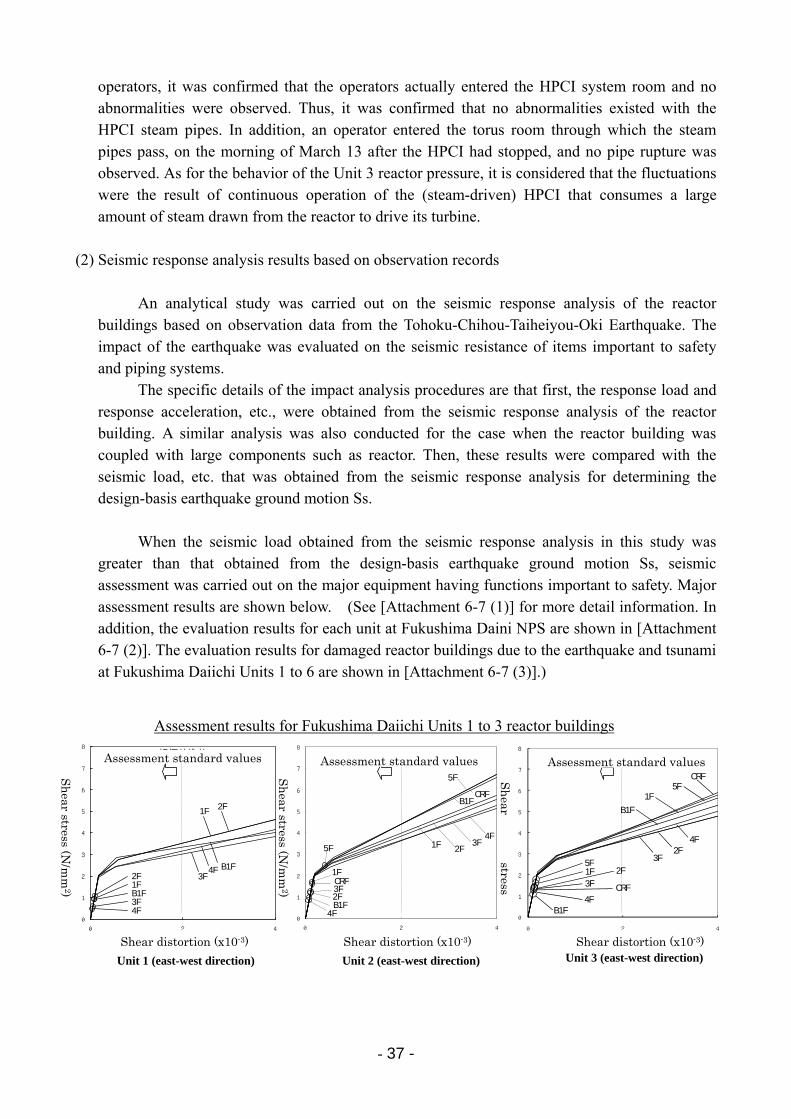
- 37 -
operators, it was confirmed that the operators actually entered the HPCI system room and no abnormalities were observed. Thus, it was confirmed that no abnormalities existed with the HPCI steam pipes. In addition, an operator entered the torus room through which the steam pipes pass, on the morning of March 13 after the HPCI had stopped, and no pipe rupture was observed. As for the behavior of the Unit 3 reactor pressure, it is considered that the fluctuations were the result of continuous operation of the (steam-driven) HPCI that consumes a large amount of steam drawn from the reactor to drive its turbine.
(2) Seismic response analysis results based on observation records
An analytical study was carried out on the seismic response analysis of the reactor buildings based on observation data from the Tohoku-Chihou-Taiheiyou-Oki Earthquake. The impact of the earthquake was evaluated on the seismic resistance of items important to safety and piping systems.
The specific details of the impact analysis procedures are that first, the response load and response acceleration, etc., were obtained from the seismic response analysis of the reactor building. A similar analysis was also conducted for the case when the reactor building was coupled with large components such as reactor. Then, these results were compared with the seismic load, etc. that was obtained from the seismic response analysis for determining the design-basis earthquake ground motion Ss.
When the seismic load obtained from the seismic response analysis in this study was
greater than that obtained from the design-basis earthquake ground motion Ss, seismic assessment was carried out on the major equipment having functions important to safety. Major assessment results are shown below. (See [Attachment 6-7 (1)] for more detail information. In addition, the evaluation results for each unit at Fukushima Daini NPS are shown in [Attachment 6-7 (2)]. The evaluation results for damaged reactor buildings due to the earthquake and tsunami at Fukushima Daiichi Units 1 to 6 are shown in [Attachment 6-7 (3)].)
Assessment results for Fukushima Daiichi Units 1 to 3 reactor buildings
4F3F
2F1FB1F
4F3F
2F1F
B1F
0
1
2
3
4
5
6
7
8
0 2 4
せん断ひずみ(×10-3)
せん断応力(N/mm2)
0
1
2
3
4
5
6
7
8
0 2 4
せん断応力(N/mm2)
せん断ひずみ(×10-3)
5F1F
CRF
4F
4F
3F
1F
B1F
B1F
5FCRF
2F
2F
3F
0
1
2
3
4
5
6
7
8
0 2 4
せん断ひずみ(×10-3)
せん断応力(N/mm2)
1FCRF3F
B1F4F
5F
CRFB1F
4F
2F3F1F5F
2F
1号機(東西方向) 3号機(東西方向)2号機(東西方向)
評価基準値 評価基準値 評価基準値
Unit 1 (east-west direction) Unit 2 (east-west direction) Unit 3 (east-west direction)Shear distortion (x10-3)
Sh
ear stress (N/m
m2)
Sh
ear stress (N/m
m2)
Sh
ear stress
Assessment standard valuesAssessment standard valuesAssessment standard values
Shear distortion (x10-3)Shear distortion (x10-3)
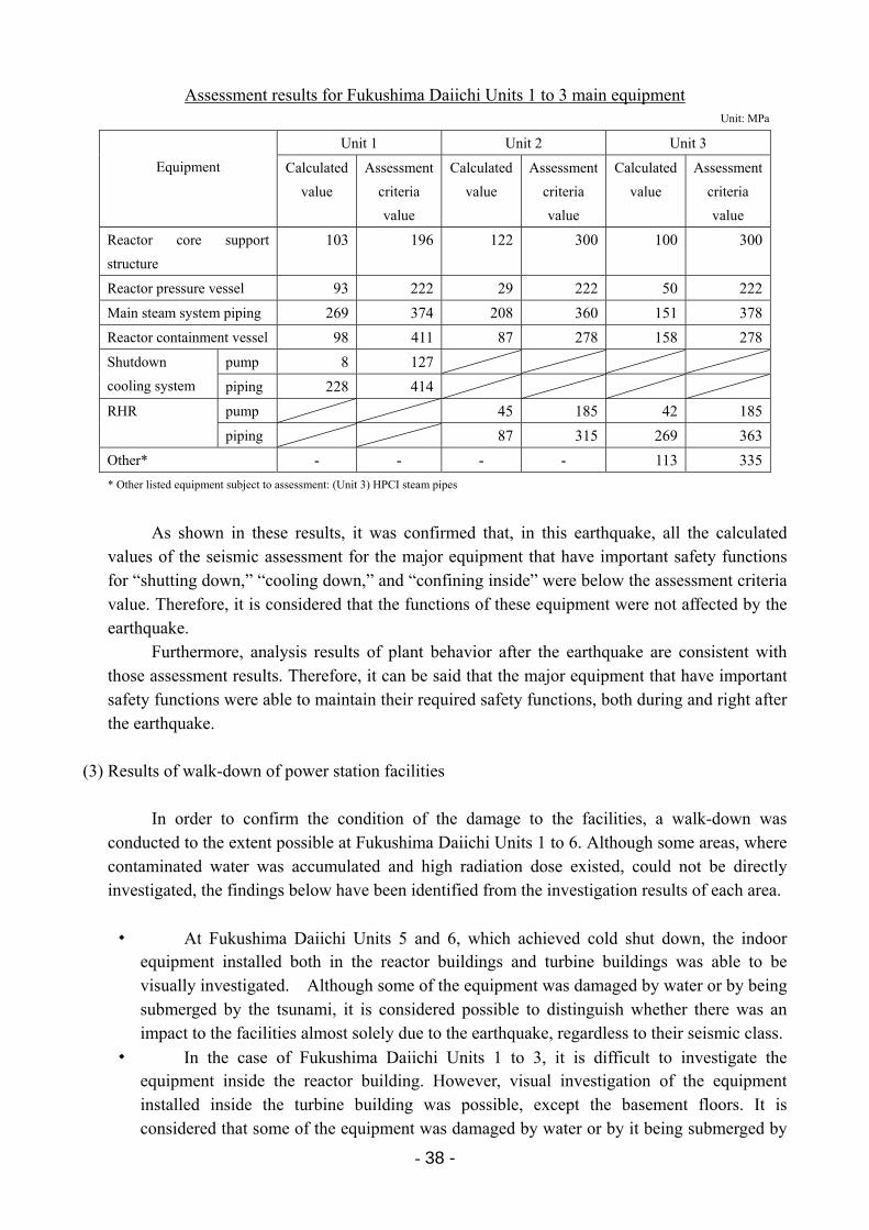
- 38 -
Assessment results for Fukushima Daiichi Units 1 to 3 main equipment Unit: MPa
Unit 1 Unit 2 Unit 3
Equipment Calculated
value
Assessment
criteria
value
Calculated
value
Assessment
criteria
value
Calculated
value
Assessment
criteria
value
Reactor core support
structure
103 196 122 300 100 300
Reactor pressure vessel 93 222 29 222 50 222
Main steam system piping 269 374 208 360 151 378
Reactor containment vessel 98 411 87 278 158 278
pump 8 127 Shutdown
cooling system piping 228 414
pump 45 185 42 185RHR
piping 87 315 269 363
Other* - - - - 113 335
* Other listed equipment subject to assessment: (Unit 3) HPCI steam pipes
As shown in these results, it was confirmed that, in this earthquake, all the calculated values of the seismic assessment for the major equipment that have important safety functions for “shutting down,” “cooling down,” and “confining inside” were below the assessment criteria value. Therefore, it is considered that the functions of these equipment were not affected by the earthquake.
Furthermore, analysis results of plant behavior after the earthquake are consistent with those assessment results. Therefore, it can be said that the major equipment that have important safety functions were able to maintain their required safety functions, both during and right after the earthquake.
(3) Results of walk-down of power station facilities
In order to confirm the condition of the damage to the facilities, a walk-down was conducted to the extent possible at Fukushima Daiichi Units 1 to 6. Although some areas, where contaminated water was accumulated and high radiation dose existed, could not be directly investigated, the findings below have been identified from the investigation results of each area.
・ At Fukushima Daiichi Units 5 and 6, which achieved cold shut down, the indoor equipment installed both in the reactor buildings and turbine buildings was able to be visually investigated. Although some of the equipment was damaged by water or by being submerged by the tsunami, it is considered possible to distinguish whether there was an impact to the facilities almost solely due to the earthquake, regardless to their seismic class.
・ In the case of Fukushima Daiichi Units 1 to 3, it is difficult to investigate the equipment inside the reactor building. However, visual investigation of the equipment installed inside the turbine building was possible, except the basement floors. It is considered that some of the equipment was damaged by water or by it being submerged by
- 39 -
the tsunami, similar to Unit 5 and Units 6. However, it can be almost confirmed that the damage was mainly from the impact of the earthquake.
・ Most of the facilities installed in turbine buildings are normal systems, and the seismic class of most of the equipment is low. Therefore, if the equipment is affected only slightly by the earthquake, it would provide essential information on the plant’s seismic resistance.
・ Damage to outdoor equipment was extensive. As mentioned below, it is considered that most of the damage was caused by the tsunami and the collisions with floating debris carried by the tsunami. However, in many cases, they cannot necessarily be used as evidence that denies the impact by the earthquake. Therefore, the causes of damage to the outdoor equipment are treated only as reference material, except for some cases in which the causes of the damage can be specified based on the damaged condition.
In addition to the above-mentioned walk-down result, the following items have been
investigated in regard to equipment with rotating parts:
・ Equipment for Units 5 and 6 that are currently in use; ・ Equipment for Units 5 and 6 that have been confirmed usable through their test runs; and ・ When the instrument was inspected by disassembling, etc., before running or conducting
test runs, the inspection result was reviewed in order to check whether any earthquake damage was found.
1) Results of Unit 5 walk-down [Attachment 6-8 (1)]
・ No damage was found from the walk-down for the facilities installed in Unit 5 reactor building.
・ Furthermore, when the walk-down was conducted for facilities installed inside the turbine building, no earthquake damage was found on EDGs, power panels, and other important equipment. A drain pipe support on the moisture separator between the high pressure turbine and low pressure turbine was askew. At one part of the small diameter pipe connected to that drain pipe, it was found to be damaged. Based on the aspects of the damages, it was determined that these were caused by the earthquake.
2) Results of Unit 6 walk-down [Attachment 6-8 (2)]
・ Unit 6 has a combination structure-type reactor buildings with annexes attached to the outer side of their reactor blocks. No external damage was found on the facilities installed in the annex section, including EDGs.
・ No major external damage was found to any of the facilities installed in the turbine building. Some cracking was found on the base of the feedwater heater (5B) support foundation. This is considered to be damage from the earthquake.
- 40 -
3) Results of Unit 1 IC walk-down [Attachment 6-8 (3)]
・ The main unit of the IC installed in the Unit 1 reactor building, main pipes, and valves were visually investigated to confirm whether or not there was any damage that could cause the reactor to lose its cooling water. Since the inside of the PCV could not be entered, main body, pipes and valves outside of the PCV were investigated.
・ On the 4th floor of the reactor building where the main unit of the IC is installed, a hole was made on the north-side ceiling due to the hydrogen explosion on the 5th floor. Some of the insulating material at the top part of the IC's north side was scattered among the rubble and considered to have been blown off by the explosion. Furthermore, the insulating material on the south side of the main unit of the IC was also severely torn off and it had fallen down, which was on the reactor building equipment hatch (opening on the floor) side. It is considered that the hydrogen explosion on the 5th floor blasted through the opening and damaged the insulating material on the IC. None of insulating materials on the 3rd or 2nd floor was found to have been torn off or scattered.
・ No damage was found on the main unit of the IC. No ruptured pipes, leakage from flange sections, and broken valves were found. Also, no trace by a blast of the high pressure steam from the reactor was found.
・ Judging from the above, it was confirmed that there was no damage to the IC equipment located outside of the PCV that could have caused loss of reactor cooling water.
・ In addition to this field walk-down, the positioning status of IC valves and IC water level were also checked. It was confirmed that Valve 2A and Valve 3A of the Subsystem-A were open, and Valve 2B and Valve 3B of the Subsystem-B were closed. Not only that, both Subsystem-A and Subsystem-B that make up feed valves to the IC were also confirmed to be closed. The IC field water level gauges (cooling water) indicated 65% for the Subsystem-A and 85% for the Subsystem-B. This was confirmed to match the instrumentation in the MCR.
4) Results of walk-down of Units 1 to 3 turbine buildings [Attachment 6-8 (4)]
・ In the case of facilities installed in the turbine buildings of Units 1 to 3, facilities installed on the 1st and 2nd floors were visually investigated. Basement floors could not be investigated because of the accumulation of contaminated water. The results, to the extent that they could be determined, were that the equipment on the 1st floor showed signs of water damage or of having been submerged by the tsunami. However, no earthquake damage was confirmed.
・ Unit 4 was undergoing outage maintenance on March 11. It was considered that much of the equipment was in a state of disassembly. Hence it was not subject to these visual inspections.
5) Results of walk-down of outdoor facilities around Units 1 to 4 [Attachment 6-8 (5)]
・ Seawater pumps for supplying seawater to equipment for cooling purposes are installed on the seaside area of turbine buildings. These pumps lost their function by the
- 41 -
tsunami. However, major pumps did not topple even with the strike of the tsunami, and were self-standing. Therefore, it is considered that there was basically no damage to the pumps by the earthquake.
・ Pumps that were either washed away or had their motors ripped off were, in addition to the pumps under disassembly inspection, small size pumps used for screen washing equipment for washing off seaweed and other debris. 《small pumps in center of photo (3)》
・ Heavy fuel oil tanks for boilers were washed away. Therefore, it is not possible to investigate the extent of damage caused by the earthquake. For EDG fuel tanks and condensate storage tanks (CSTs), which were one of the cooling water sources, ground subsidence around the basement was observed. It is considered to be as a result of the earthquake. However, no leakage or other damage was found on the tanks themselves.《photo (7) and photos (8), (9)》
・ Power panels for the water intake facilities that are installed outside were destroyed, which may be because the shape was vulnerable to the pressure from the tsunami. Therefore, the extent of damage by the earthquake cannot be determined. 《photo (13)》
6) Results of walk-down of filtered water tanks, pure water storage tanks, etc.
[Attachment 6-8 (6)]
・ The pure water storage tank was damaged by buckling as a result of the earthquake (typically observed in the lower part of the No. 1 pure water storage tank, as shown in the center photo, upper row). It is also confirmed that the No. 1 pure water storage tank had some water leakage from the short flexible section connecting the pipes attached to the tank to the outer piping when the earthquake hit. The leakage was reduced by shutting off the tank-side valve. The No. 2 pure water storage tank was damaged at its base by the earthquake, from which an insignificant amount of water leaked continuously.
・ The filtered water tank was damaged by buckling similar to the pure water storage tank. However, no leakage has been identified.
・ The coupling section of the filtered water tank that is the water source of the transformer’s fire protection pipe was disjoined and this resulted in leakage. This fire protection pipe was installed at the lower section of a slope, and crossed another pipe that came down the slope. The slope collapsed due to the earthquake, and the pipe that was laid along the slope was displaced at the supporting point.
It is considered that this lurching support pushed the coupling section of the fire protection pipe located at the crossing point, causing the coupling section to be torn loose. The damage is considered to have been caused by secondary impacts of the earthquake.
7) Results of walk-down of outdoor FP pipes [Attachment 6-8 (7)]
・ The state of damage to the outdoor FP pipes was investigated. Reflecting lessons from the Niigata-Chuetsu-Oki Earthquake, FP pipes were routed on the ground, and countermeasures such as welded structures were applied. Modification was also carried out at the power stations so that the FP pipes could be used to inject water into the RPV. In
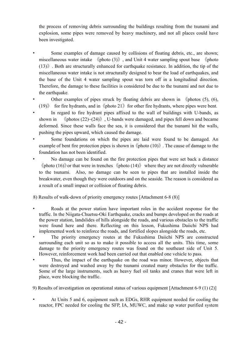
- 42 -
the process of removing debris surrounding the buildings resulting from the tsunami and explosion, some pipes were removed by heavy machinery, and not all places could have been investigated.
・ Some examples of damage caused by collisions of floating debris, etc., are shown; miscellaneous water intake 《photo (3)》, and Unit 4 water sampling spout base 《photo (13)》. Both are structurally enhanced for earthquake resistance. In addition, the tip of the miscellaneous water intake is not structurally designed to bear the load of earthquakes, and the base of the Unit 4 water sampling spout was torn off in a longitudinal direction. Therefore, the damage to these facilities is considered be due to the tsunami and not due to the earthquake.
・ Other examples of pipes struck by floating debris are shown in 《photos (5), (6), (19)》 for fire hydrants, and in《photo 21》for other fire hydrants, where pipes were bent.
・ In regard to fire hydrant pipes affixed to the wall of buildings with U-bands, as shown in 《photos (22)~(24)》, U-bands were damaged, and pipes fell down and became deformed. Since these walls face the sea, it is considered that the tsunami hit the walls, pushing the pipes upward, which caused the damage.
・ Some foundations on which the pipes are laid were found to be damaged. An example of bent fire protection pipes is shown in《photo (10)》. The cause of damage to the foundation has not been identified.
・ No damage can be found on the fire protection pipes that were set back a distance 《photo (16)》or that were in trenches 《photo (14)》 where they are not directly vulnerable to the tsunami. Also, no damage can be seen to pipes that are installed inside the breakwater, even though they were outdoors and on the seaside. The reason is considered as a result of a small impact or collision of floating debris.
8) Results of walk-down of priority emergency routes [Attachment 6-8 (8)]
・ Roads at the power station have important roles in the accident response for the
traffic. In the Niigata-Chuetsu-Oki Earthquake, cracks and bumps developed on the roads at the power station, landslides of hills alongside the roads, and various obstacles to the traffic were found here and there. Reflecting on this lesson, Fukushima Daiichi NPS had implemented work to reinforce the roads, and fortified slopes alongside the roads, etc.
・ The priority emergency routes at the Fukushima Daiichi NPS are constructed surrounding each unit so as to make it possible to access all the units. This time, some damage to the priority emergency routes was found on the southeast side of Unit 5. However, reinforcement work had been carried out that enabled one vehicle to pass.
・ Thus, the impact of the earthquake on the road was minor. However, objects that were destroyed and washed away by the tsunami created many obstacles for the traffic. Some of the large instruments, such as heavy fuel oil tanks and cranes that were left in place, were blocking the traffic.
9) Results of investigation on operational status of various equipment [Attachment 6-9 (1) (2)]
・ At Units 5 and 6, equipment such as EDGs, RHR equipment needed for cooling the
reactor, FPC needed for cooling the SFP, IA, MUWC, and make up water purified system
- 43 -
(MUWP) that have the role of supplying water and valve operation, etc., are placed in service, or confirmed to be operable and placed standby.
・ Of the above equipment, pumps and other machines installed in the highly air-tight reactor building were unaffected by the earthquake. They were in operation following prior checks, and their integrity has been confirmed.
・ Non-conformances such as minor leakage have been confirmed for equipment installed in turbine buildings, which was inundated by a large amount of seawater. However, no damage to the main unit of those equipment were found due to the earthquake. This equipment are in operable condition after necessary inspections have been conducted.
・ Regarding pumps for sea water systems that are installed outdoors, some small diameter pipes attached to motors were damaged by the tsunami, and bearings were damaged by sand. These damaged motors and bearings were replaced and then put into operation. No example has been found of lost function due to the earthquake.
As mentioned above, based on the investigation performed up to present, most equipment
was unaffected by the earthquake. This is not only the case for safety-related equipment, but also that for equipment with low seismic class.
Note that at the bottom-most basement floor of the Unit 5 reactor building, seismic acceleration measured 548 gals. This is equivalent to the acceleration data at Unit 2, which recorded the largest.
(4) Summary of impact assessment on facilities
As described above, the results of the analysis on the seismic resistance assessment of Fukushima Daiichi NPS based on the plant operational conditions and observed seismic motion show that the major equipment that has important functions from the perspective of safety is considered to have maintained its safety functions throughout and immediately following the earthquake.
Furthermore, judging from the results of the walk-down inside the plant and some of the Unit 5 and Unit 6 equipment that was already in operation or had already undergone test runs, the main equipment having important functions from the perspective of safety was not found to have any damage resulting from the earthquake, and even that equipment of lesser seismic design grade showed hardly any damage affecting functionality resulting from the quake itself.
Accordingly, it is considered that the state of plant responses implemented at the time of, and in the moments immediately following, the earthquake were appropriate and efforts to maintain backup power by means of EDGs were successful, despite the loss of off-site power caused by the earthquake.
At the Fukushima Daini NPS, reactors were automatically shut down and the emergency
cooling system equipment pumps simultaneously started up automatically after the earthquake. The system had operated as designed until the arrival of the tsunami. The plants suffered no damage to the reactor cores and successfully and safely achieved cold shut down. Also, plant walk-downs that were performed later found no damage to the functions of equipment important to safety except for the damage by the tsunami. Thus it is considered that the earthquake had no impact on the functionality of items important to safety.
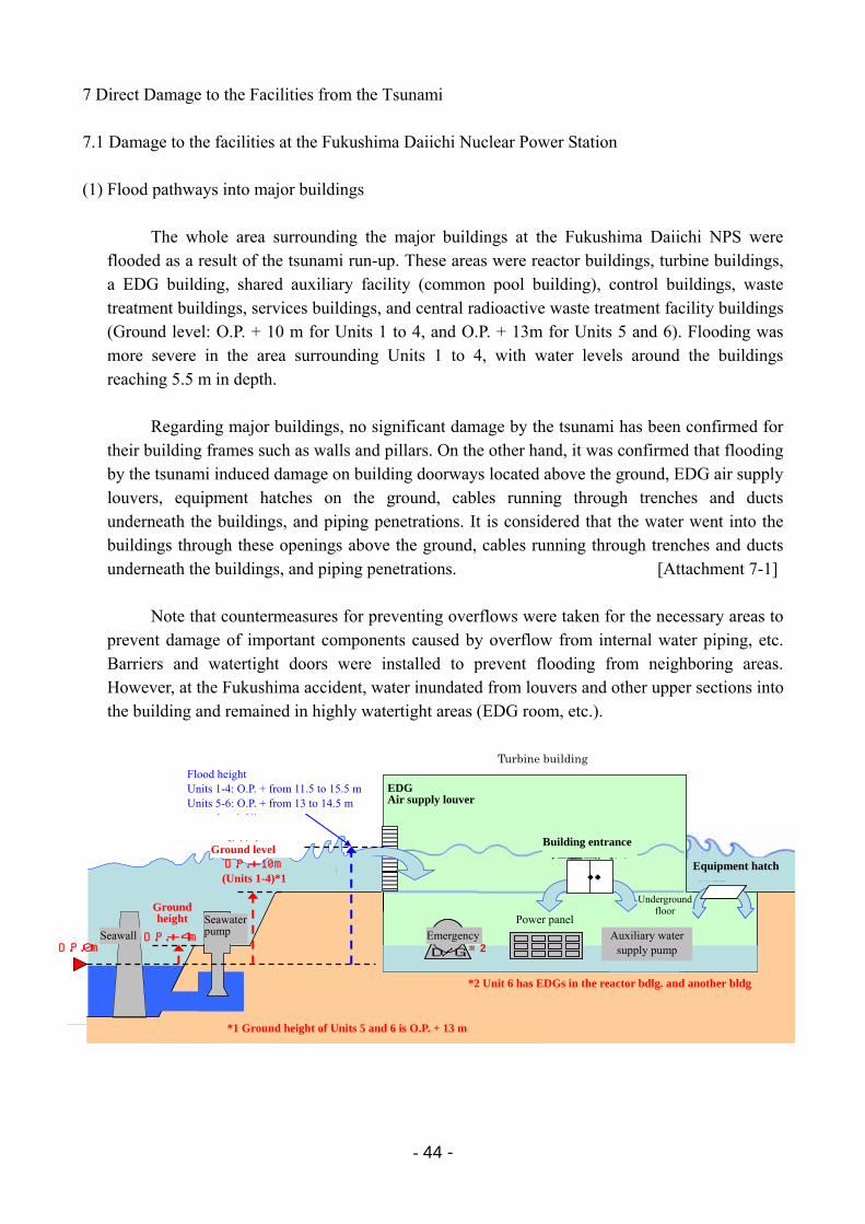
- 44 -
7 Direct Damage to the Facilities from the Tsunami 7.1 Damage to the facilities at the Fukushima Daiichi Nuclear Power Station (1) Flood pathways into major buildings
The whole area surrounding the major buildings at the Fukushima Daiichi NPS were flooded as a result of the tsunami run-up. These areas were reactor buildings, turbine buildings, a EDG building, shared auxiliary facility (common pool building), control buildings, waste treatment buildings, services buildings, and central radioactive waste treatment facility buildings (Ground level: O.P. + 10 m for Units 1 to 4, and O.P. + 13m for Units 5 and 6). Flooding was more severe in the area surrounding Units 1 to 4, with water levels around the buildings reaching 5.5 m in depth.
Regarding major buildings, no significant damage by the tsunami has been confirmed for
their building frames such as walls and pillars. On the other hand, it was confirmed that flooding by the tsunami induced damage on building doorways located above the ground, EDG air supply louvers, equipment hatches on the ground, cables running through trenches and ducts underneath the buildings, and piping penetrations. It is considered that the water went into the buildings through these openings above the ground, cables running through trenches and ducts underneath the buildings, and piping penetrations. [Attachment 7-1]
Note that countermeasures for preventing overflows were taken for the necessary areas to prevent damage of important components caused by overflow from internal water piping, etc. Barriers and watertight doors were installed to prevent flooding from neighboring areas. However, at the Fukushima accident, water inundated from louvers and other upper sections into the building and remained in highly watertight areas (EDG room, etc.).
吸気ルーバーからの進入
防波堤海水ポンプ
非常用D/G給気ルーバー
タービン建屋
敷地高さO.P.+10m
(1~4号機※1)
敷地高さO.P.+4m
※1 5・6号機の敷地高さはO.P.+13m
O.P.0m
浸水高1~4号機:O.P.+11.5~15.5m5,6号機:O.P.+13~14.5m
※2 6号機D/Gは原子炉建屋等別建屋に配置
建屋出入口
機器ハッチ・・
非常用D/G非常用D/G
電源盤
※2補給水ポンプ
地下階
EDGAir supply louver
Equipment hatch
Ground height
(Units 1-4)*1
Ground level
Flood height Units 1-4: O.P. + from 11.5 to 15.5 m Units 5-6: O.P. + from 13 to 14.5 m
*2 Unit 6 has EDGs in the reactor bdlg. and another bldg
Emergency Auxiliary water supply pump
Seawall Seawater pump
Turbine building
Building entrance
Power panel
Underground floor
*1 Ground height of Units 5 and 6 is O.P. + 13 m
- 45 -
(2) Facility damage due to the tsunami
In this section, details are provided regarding reactor cooling equipment that suffered typical damage by the tsunami.
1) Emergency seawater system pumps
Seawater is used for removal of decay heat in Units 1 to 6. Except for several air-cooling systems, EDGs also utilize seawater for cooling machinery. Thus, emergency seawater system pumps* have been installed at the ocean side of the site to take in seawater.
The ground level of these areas with emergency seawater system pumps is O.P. + 4m. Based on an analysis results on tsunami height, countermeasures were implemented so that the functions could be maintained even for a 5.4 to 6.1m-height tsunami. However, the tsunami height on March 11 was far beyond this. Therefore, electric motors for these pumps were flooded and lost their functions.
Regarding emergency seawater system pumping equipment installed in the yard,
pumps and attached equipment were damaged by collapsing cranes for inspection and collisions of floating debris. There were also cases of seawater mixing in with lubricating oil for electric motor bearings. However, except for RHR seawater system pumps A and C, which had been removed for inspection at Unit 4, the tsunami did not wash away or even move any pumps from their original locations. Mechanical damage to emergency seawater system pumps was limited. The seawater pumps to cool D/G (6A) at Unit 6, for example, were able to be restarted on March 18, 2011 without performing any repair. It then allowed D/G (6A) to startup on March 19, 2011. [Attachment 7-2]
*: The emergency seawater system pump equipment refers to seawater system pumps for PCV cooling,
RHR seawater system pumps, and EDG seawater pumps.
2) Emergency diesel generators
As a result of water flooding into the whole area surrounding the major buildings,
water intruded into buildings and electrical equipment inside the buildings lost its function The water-cooled EDGs at Units 5 and 6 (D/G (5A), D/G (5B), D/G (6A), and high
pressure core spray system (HPCS) D/G) were not flooded. However the water-cooled EDGs at Units 1 to 4 malfunctioned due to water damage. Water-cooled EDGs at Units 5 and 6 that were not damaged by water could not continue running due to a loss of function of their emergency seawater system pumps and other equipment. Consequently, all the water-cooled EDGs stopped running.
On the other hand, the air-cooled EDGs (D/G (2B) for Unit 2, D/G (4B) for Unit 4, D/G (6B) for Unit 6) did not have emergency seawater system pumps. Therefore their cooling systems were not affected by the tsunami. Regarding D/G (2B) and D/G (4B), they are installed in the shared auxiliary facility (common pool building) to the southwest of Unit 4 reactor building. For those equipment, there was no flood damage on the main units. However, they also stopped functioning because the electrical equipment room in the
- 46 -
basement of the shared auxiliary facility (common pool building) was flooded and the EDG power panels lost their functions due to flooding.
This caused all the EDGs for Units 1 to 5 to stop, resulting in a station black out. The air-cooled D/G (6B) for Unit 6 continued to run without power being lost.
[Attachment 7-3]
3) Power panels
Off-site power and EDG power is supplied to equipment via high-voltage power panels, power centers, and low-voltage power panels. In case of loss of AC power, DC power panels (with batteries) are available to maintain minimum monitoring functions.
At Units 1 to 5, due to the tsunami, all high-voltage power panels for both ordinary and
emergency systems were damaged by water due to the tsunami. Therefore, electric power could not have been supplied to the necessary equipment even if off-site power and EDG had been functioning.
Most of the power centers were also damaged by water, leaving few places where
high-voltage power supply cars could be connected. Regarding damage to DC power panels, they were damaged by water at Units 1, 2 and
4, however, not at Units 3, 5, and 6. It is presumed that the fact that the DC power panels at Units 3, 5, and 6 were installed on the semi-basement level of the turbine building saved them from water damage.
Flooding was most apparent on the lowest basement levels in facilities where buildings
were heavily flooded. The damage to power panels has consistency with this. Power panels on the lowest basement floors were damaged by water, while power panels except some on the semi-basement floors were not.
Even on the lowest basement floors, it was not flooded in the case where EDG air supply louvers, etc., were installed above the flood depth and no penetrations for the ducts, trenches, etc., that could serve as inundation pathways existed. This was the case for equipment such as EDGs for Units 5 and 6 and emergency power panels (high-voltage power panels and power centers) at Unit 6.
At Unit 6, the power panels (D system for emergency power supply systems) including high-voltage power panels and power centers were not damaged along with the air-cooled D/G (6B) itself. Therefore, the equipment could maintain power supply to the connected facilities. [Attachment 7-4]
4) Damage on outdoor facilities
A large amount of floated debris remained in the vicinity of the Fukushima Daiichi
NPS. This included the No. 1 heavy oil tank (with a diameter of 11.7m, height of 9.2m, and weight of 32 tons) that had been installed on the seaward side (ground level: O.P. + 4m) being floated by the tsunami to the road on the north side of the reactor and turbine buildings
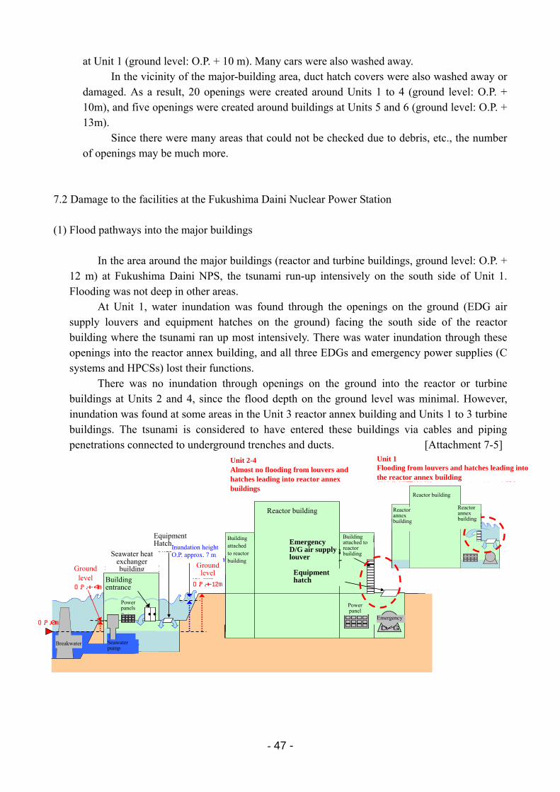
- 47 -
at Unit 1 (ground level: O.P. + 10 m). Many cars were also washed away. In the vicinity of the major-building area, duct hatch covers were also washed away or
damaged. As a result, 20 openings were created around Units 1 to 4 (ground level: O.P. + 10m), and five openings were created around buildings at Units 5 and 6 (ground level: O.P. + 13m).
Since there were many areas that could not be checked due to debris, etc., the number of openings may be much more.
7.2 Damage to the facilities at the Fukushima Daini Nuclear Power Station
(1) Flood pathways into the major buildings
In the area around the major buildings (reactor and turbine buildings, ground level: O.P. + 12 m) at Fukushima Daini NPS, the tsunami run-up intensively on the south side of Unit 1. Flooding was not deep in other areas.
At Unit 1, water inundation was found through the openings on the ground (EDG air supply louvers and equipment hatches on the ground) facing the south side of the reactor building where the tsunami ran up most intensively. There was water inundation through these openings into the reactor annex building, and all three EDGs and emergency power supplies (C systems and HPCSs) lost their functions.
There was no inundation through openings on the ground into the reactor or turbine buildings at Units 2 and 4, since the flood depth on the ground level was minimal. However, inundation was found at some areas in the Unit 3 reactor annex building and Units 1 to 3 turbine buildings. The tsunami is considered to have entered these buildings via cables and piping penetrations connected to underground trenches and ducts. [Attachment 7-5]
吸気ルーバーからの進入吸気ルーバーからの進入
吸気ルーバーからの進入
防波堤
敷地高さO.P.+4m
O.P.0m
2~4号機原子炉建屋付属棟へのルーバーやハッチからの浸水はほとんどなし
海水熱交換器建屋
電源盤・・
建屋出入口敷地高さO.P.+12m
浸水高 O.P.約7m非常用D/G給気ルーバー
機器ハッチ
海水ポンプ
原子炉建屋
原子炉建屋付属棟
原子炉建屋付属棟
機器ハッチ
電源盤
非常用D/G
原子炉建屋付属棟
原子炉建屋
原子炉建屋付属棟
1号機原子炉建屋付属棟へルーバーやハッチから浸水
Emergency D/G air supply louver
Reactor building
Building entrance
Building attached to reactor building
Equipment hatch
Power panel
Power panels
Seawater pump
Breakwater
Ground level
Unit 2-4 Almost no flooding from louvers and hatches leading into reactor annex buildings
Unit 1 Flooding from louvers and hatches leading into the reactor annex building
Equipment Hatch
Emergency
Seawater heat exchanger building Ground
level
Inundation height O.P. approx. 7 m
Building attached to reactor building
Reactor annex building
Reactor annex building
Reactor building
- 48 -
(2) Facility damage due to the tsunami
In this section, details are provided regarding reactor cooling equipment that suffered typical damage by the tsunami.
1) Emergency seawater system pumps
Seawater is used for the removal of decay heat in Units 1 to 4. The EDGs also utilize
seawater for cooling machinery. Thus, emergency seawater system pumps* have been installed at the ocean side of the site to take in seawater.
The ground level of these areas with emergency seawater system pumps is O.P. + 4 m. Based on analysis results on tsunami height, countermeasures were implemented so that the functions could be maintained even for a 5.1 to 5.2m-height tsunami. However, the tsunami height on March 11 was far beyond this. Therefore, electric motors for these pumps were flooded and lost their functions.
Emergency seawater system pumps were installed in the heat exchanger buildings at
Fukushima Daini NPS. The area around the heat exchanger buildings was flooded at about 3m in height by the tsunami. Although the frameworks of these buildings were not damaged, doors and other ground-level openings were damaged and all the heat exchanger buildings were flooded.
As a result, power panels and pump motors were damaged by water. Among the eight RHR seawater systems at the station, seven except one for Unit 3 lost their functions. All the EDG seawater systems—which consist of A, B, and H systems—lost their functions except for 3 systems, that is, B and H systems for Unit 3 and H system for Unit 4.
*: The emergency seawater system pump equipment refers to RHR seawater system pumps and intermediate loop cycle pumps, intermediate loop cycle pumps for EDG systems, and seawater pumps and intermediate loop cycle pumps for HPCS D/G equipment cooling systems.
2) Emergency diesel generators
For every unit at the Fukushima Daini NPS, three (A, B, H) EDGs are installed. At
Unit 1, water flooded into the reactor annex building from ground-level openings. All the three EDGs were then damaged by the water and lost their functions. Even if the EDG’s main units themselves were not damaged by flooding, they lost their functions if the power panels or the pump motors of the EDG seawater systems were damaged by water since they could no longer be cooled. All the EDG seawater cooling systems lost their functions except for 3 systems, B and H for Unit 3 and H for Unit 4. As a result, 9 EDGs lost their functions; that is, Unit 1 EDGs (A, B, and H), Unit 2 EDGs (A, B, and H), Unit 3 EDG (A), and Unit 4 EDGs (A and B).
Note that off-site power was available at the Fukushima Daini NPS; there was no need to use those EDGs that survived. [Attachment 7-6]
- 49 -
3) Power panels
The scale of the tsunami observed at the Fukushima Daini NPS was different from the one observed at the Fukushima Daiichi NPS. Therefore, the amount of seawater flooding into the major buildings was different, and the resulting damage to power panels was different. In the Unit 1 reactor annex building where there was tsunami water inundation, Systems C and H for emergency power panels were damaged by water while D was not. None of the power panels were damaged in major buildings at other units. Hence, it was possible to supply off-site power to equipment through emergency power supply systems. This made it possible to use necessary facilities during the following emergency response. (Power supply systems consist of two ordinary systems A and B, two emergency systems C and D, and HPCS power supply system H)
On the other hand, power panels installed in the heat exchanger buildings on the seaside area were damaged by the flooding. Seven out of eight power centers were damaged by water, and only one power center in the Unit 3 heat exchanged building survived. As a result, all eight RHR seawater systems except one for Unit 3 lost their functions.
[Attachment 7-7]
4) Damage to the other outdoor facilities
At the Fukushima Daini NPS, none of major equipment and structures were found to have drifted to the major buildings area (ground level: O.P. + 12m) due to tsunami.
There were, however, five locations where openings were created due to the washing away of, or damage done to, hatch lids on ducts in the major buildings area.
7.3 Summary of the damage to the facilities due to the tsunami (1) Summary of damage at the Fukushima Daiichi Nuclear Power Station
The hardships below were encountered as a result of tsunami damage to facilities at the Fukushima Daiichi NPS.
1) The tsunami after the earthquake caused emergency seawater system pump equipment
to lose its function at all units. This prevented residual heat (decay heat) from being removed from the reactor by seawater.
2) Loss of power supply function at Units 1 to 5 caused all motor-operated facilities (safety systems, water injection and cooling equipment, etc.) to be rendered unusable. Motor-operated valves were no longer operable from the MCR.
3) At Units 1, 2, and 4, where DC power was also lost, all monitoring instruments in the MCR became unavailable, preventing the monitoring of the plant status. At Units 3 and 5, where DC power was available, measurements and monitoring of the plant condition were influenced by the battery levels.
- 50 -
4) SRVs for reactor depressurization and solenoid valves for controlling air-operated vent valves for the PCV also became inoperable.
5) In addition, lack of communication tools and power outages that affected lighting in the MCRs, buildings, and outside field made emergency response even more difficult.
6) Debris and residual water due to the tsunami and the risk of further tsunami made the working environment much harder in the field outside.
That is, it became impossible to remove heat from the reactor, power to all electrical
equipment was lost, MCRs lost their monitoring and operating functions, communication tools with the workers in the field were lost, and lightning were gone. Under such circumstances, workers had to begin emergency response measures.
Regarding MUWC pumps for Units 1 to 4, which is vial equipment for an alternative water injection, they were unavailable not only because of the loss of electric power supply, but also because of water damage to their motors.
Thus, tsunami damage on facilities brought many difficulties in responding to the accident. (See [Attachment 7-8] for the status of damage to major equipment related to safety systems, etc.)
(2) Summary of damage at the Fukushima Daini Nuclear Power Station
At the Fukushima Daini NPS, the scale of the tsunami was different, and the resulting damage to facilities was different. The tsunami after the earthquake caused the loss of the emergency seawater system pump equipment at Units 1, 2, and 4. This prevented residual heat (decay heat) from being removed from the reactor via seawater cooling.
However, since emergency power supply systems remained available for all the units, it was possible to use alternative low-pressure water injection systems such as MUWC systems. The MCR's monitoring and control functions were also maintained. (See [Attachment 7-9] for the status of damage to major equipment related to safety systems, etc.)
- 51 -
8 Response Status after Tsunami
Ordinarily, when an operating reactor automatically shuts down (automatic scram), heat from fission of the fuel in all the control rods inserted is no longer generated. However, decay heat from fission products in the fuel continues to be emitted. On account of this, a core must be continually cooled even after shutdown, and when cooling is not able to be continued, there is the risk that reactor water level may decrease, resulting in core damage, and that the radioactive materials can no longer be contained.
This accident was an event in which reactor cooling could not be accomplished by
ordinary measures due to the tsunami. In the accident response, the cooling water injection and the PCV venting operation were the primary recovery work due to cooling the reactor core and maintaining the PCV pressure at its operational limit, respectively. Particularly, the focus was on cooling water injection into the reactor, and seawater as well as freshwater was injected into the reactor.
For Fukushima Daiichi Units 1 to 3, which were operating, the recovery work was started in a severe environment, such as the obstruction of scattered debris and the danger of open trenches due to the tsunami.
Hereafter, based on the results of interviews with a total of over 250 workers, the recovery
operation and work status at the time the accident occurred are described for not only Fukushima Daiichi Units 1 to 3 as previously mentioned, but also for the other Fukushima Diiachi Units and the Fukushima Daini NPS*. The detailed records collected of the interview results are given in the attachments (“Response Situation at Fukushima Daiichi NPS and Fukushima Daini NPS”).
* In regard to the Fukushima Daini NPS, the status of Unit 1 was described as a typical example, while
the other two plants followed almost the same progression of events, except Unit 3, at which the
function of the emergency seawater system was able to be ensured.
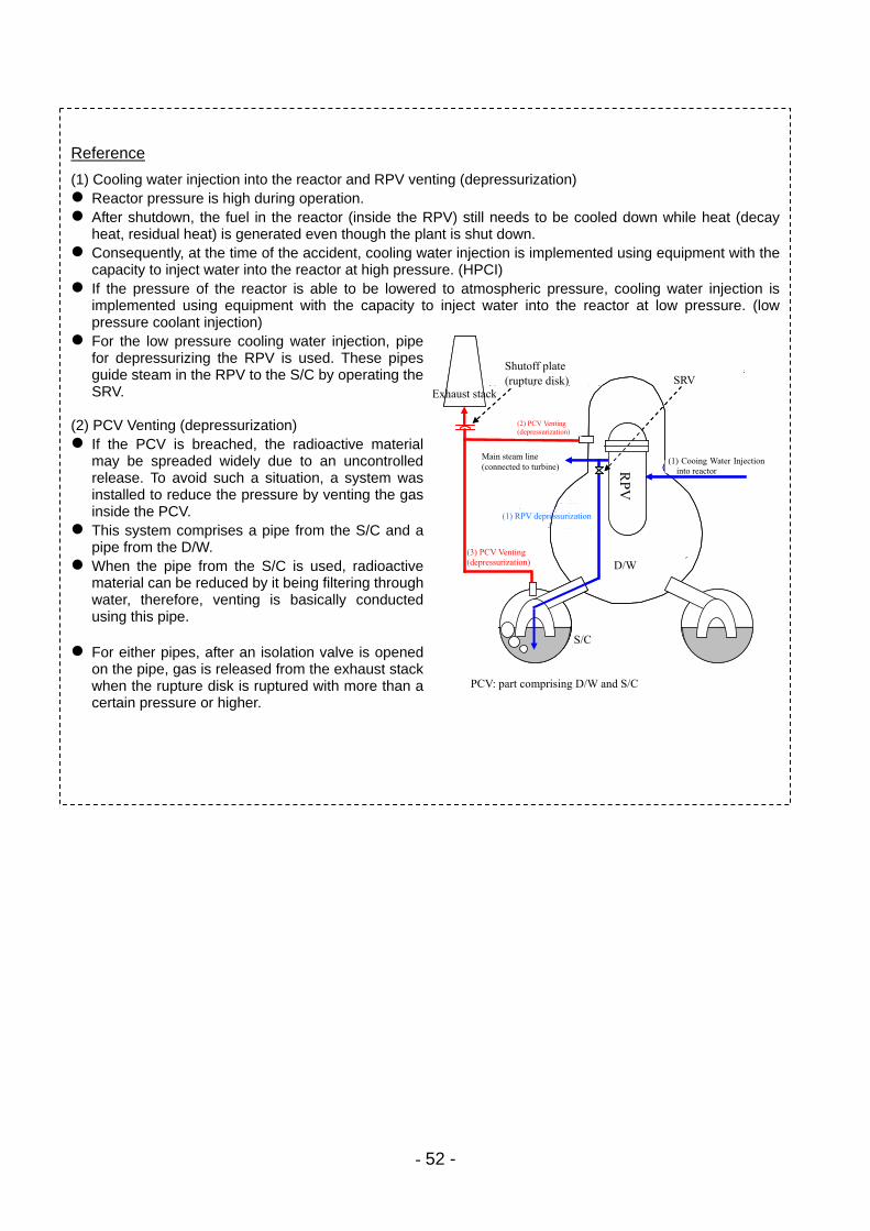
- 52 -
Reference
(1) Cooling water injection into the reactor and RPV venting (depressurization) Reactor pressure is high during operation. After shutdown, the fuel in the reactor (inside the RPV) still needs to be cooled down while heat (decay
heat, residual heat) is generated even though the plant is shut down. Consequently, at the time of the accident, cooling water injection is implemented using equipment with the
capacity to inject water into the reactor at high pressure. (HPCI) If the pressure of the reactor is able to be lowered to atmospheric pressure, cooling water injection is
implemented using equipment with the capacity to inject water into the reactor at low pressure. (low pressure coolant injection)
For the low pressure cooling water injection, pipe for depressurizing the RPV is used. These pipes guide steam in the RPV to the S/C by operating the SRV.
(2) PCV Venting (depressurization) If the PCV is breached, the radioactive material
may be spreaded widely due to an uncontrolled release. To avoid such a situation, a system was installed to reduce the pressure by venting the gas inside the PCV.
This system comprises a pipe from the S/C and a pipe from the D/W.
When the pipe from the S/C is used, radioactive material can be reduced by it being filtering through water, therefore, venting is basically conducted using this pipe.
For either pipes, after an isolation valve is opened
on the pipe, gas is released from the exhaust stack when the rupture disk is ruptured with more than a certain pressure or higher.
圧力容器
ドライウェル
圧力抑制室
排気筒
①原子炉への注水
①圧力容器のベント(減圧)
③格納容器のベント(減圧)
格納容器:ドライウェルと圧力抑制室をあわせた部分
③格納容器のベント(減圧)
主蒸気配管(タービンへ)
主蒸気逃がし安全弁閉止板(ラプチャーディスク)
圧力容器
ドライウェル
圧力抑制室
排気筒
①原子炉への注水
①圧力容器のベント(減圧)
③格納容器のベント(減圧)
格納容器:ドライウェルと圧力抑制室をあわせた部分
③格納容器のベント(減圧)
主蒸気配管(タービンへ)
主蒸気逃がし安全弁閉止板(ラプチャーディスク)
PCV: part comprising D/W and S/C
SRV Shutoff plate (rupture disk)
Exhaust stack
(2) PCV Venting (depressurization)
Main steam line (connected to turbine)
(1) Cooing Water Injection into reactor
(3) PCV Venting (depressurization)
S/C
D/W
RP
V
(1) RPV depressurization
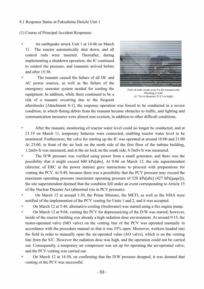
- 53 -
Fuel oil tank swept away by the tsunami and blocking a road
(11.7m in diameter X 9.2 m high)
8.1 Response Status at Fukushima Daiichi Unit 1 (1) Course of Principal Accident Responses
・ An earthquake struck Unit 1 at 14:46 on March 11. The reactor automatically shut down, and all control rods were inserted. Thereafter, during implementing a shutdown operation, the IC continued to control the pressure, and tsunamis arrived before and after 15:30.
・ The tsunami caused the failure of all DC and AC power sources, as well as the failure of the emergency seawater system needed for cooling the equipment. In addition, while there continued to be a risk of a tsunami occurring due to the frequent aftershocks [Attachment 8-1], the response operation was forced to be conducted in a severe condition, in which floting debris from the tsunami became obstacles to traffic, and lighting and communication measures were almost non-existent, in addition to other difficult conditions.
・ After the tsunami, monitoring of reactor water level could no longer be conducted, and at 21:19 on March 11, temporary batteries were connected, enabling reactor water level to be monitored. Furthermore, the valve for starting up the IC was operated at around 18:00 and 21:00. At 23:00, in front of the air lock on the north side of the first floor of the turbine building, 1.2mSv/h was measured, and at the air lock on the south side, 0.5mSv/h was measured.
・ The D/W pressure was verified using power from a small generator, and there was the possibility that it might exceed 600 kPa[abs]. At 0:06 on March 12, the site superintendent (director, of ERC at the power station) gave instructions to proceed with preparations for venting the PCV. At 0:49, because there was a possibility that the PCV pressure may exceed the maximum operating pressure (maximum operating pressure of 528 kPa[abs] (427 kPa[gage])), the site superintendent deemed that the condition fell under an event corresponding to Article 15 of the Nuclear Disaster Act (abnormal rise in PCV pressure).
・ On March 12 at around 1:30, the Prime Minister, the METI, as well as the NISA were notified of the implemention of the PCV venting for Units 1 and 2, and it was accepted.
・ On March 12 at 5:46, alternative cooling (freshwater) was started using a fire engine pump. ・ On March 12 at 9:04, venting the PCV for depressurizing of the D/W was started; however,
inside of the reactor building was already a high radiation dose environment. At around 9:15, the motor-operated valve (MO valve) on the venting line of the PCV was operated manually in accordance with the procedure manual so that it was 25% open. Moreover, workers headed into the field in order to manually open the air-operated value (AO valve), which is on the venting line from the S/C. However the radiation dose was high, and the operation could not be carried out. Consequently, a temporary air compressor was set up for operating the air-operated valve, and the PCV venting was carried out.
・ On March 12 at 14:30, on confirming that the D/W pressure dropped, it was deemed that venting of the PCV was successful.
- 54 -
・ On March 12 at around 14:54, the site superintendent ordered the injection of seawater into the reactor.
・ Subsequently, on March 12 at 15:36, an explosion, which was thought to be attributable to hydrogen gas, occurred in the upper structure of the reactor building, and the roof and outer walls of the refueling floor (top floor) were damaged. This explosion damaged the hose for seawater injection, and workers were evacuated from the field and confirmation of their safety was carried out. The restoration and preparation work was suspended until the field conditons could be verified. During these processes, radioactive materials were released into the environment; therefore, the radiation dose in the area surrounding the site increased.
・ On March 12 at 19:04, a FP line was used, and the seawater injection was commenced.
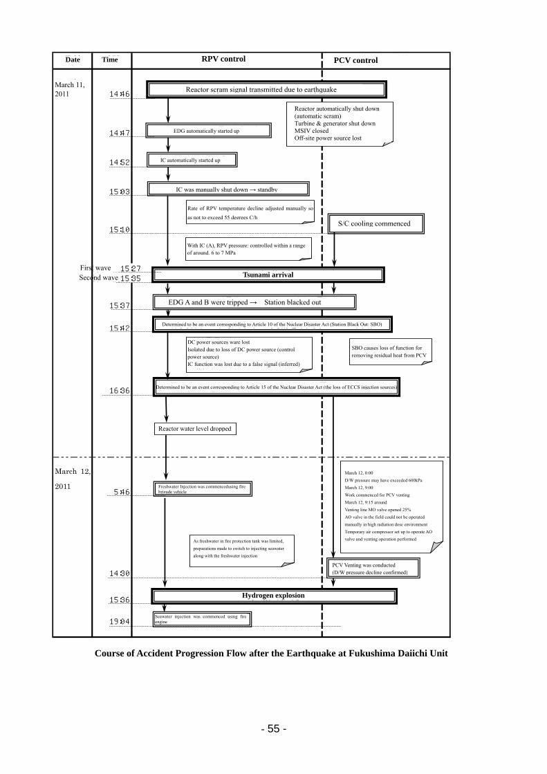
- 55 -
2011年3月11日 14:46
14:47
14:52
15:03
15:10
第一波15:27第二波15:35
15:37
15:42
16:36
2011年3月12日
5:46
14:30
15:36
19:04
福島第一発電所1号機 地震後の事故進展の流れ
日付 時間 原子炉制御 格納容器制御
圧力抑制室冷却開始
原子炉水位低下
原災法第15条該当事象(非常用炉心冷却装置注水不能)と判断
非常用復水器自動起動
非常用復水器手動停止 → 待機状態
地震による原子炉スクラム信号発信
津 波 襲 来
格納容器ベント実施(D/W圧力低下確認)
水 素 爆 発
原災法第10条該当事象(全交流電源喪失:SBO)と判断
・SBOにより格納容器除熱 機能喪失
・原子炉自動停止(自動スクラム)・タービン・発電機停止・主蒸気隔離弁閉止・外部電源喪失
・原子炉圧力容器温度降下率が55℃/h を超えないよう手動にて調整操作
・非常用復水器A系にて 原子炉圧力:約6~7MPaの範囲で制御
・直流電源喪失・直流電源(制御電源)喪失による隔離 誤信号により非常用復水器機能喪失 (推定)
非常用ディーゼル発電機自動起動
非常用ディーゼル発電機A,Bトリップ → 全交流電源喪失
消防車による淡水注入開始
・3月12日 0時頃 ・D/W圧力が600kPaを超えて いる可能性・3月12日 9時頃 ・格納容器ベントを行う作業開始・3月12日 9時15分頃 ・ベントラインMO弁25%開 ・現場のAO弁は高放射線環境 下で手動操作できず ・仮設空気圧縮機を設置しAO弁 を操作しベント操作実施
消防車による海水注入開始
・防火水槽の淡水には限りがある ため、淡水注入と並行して海水注 入への切り替え準備
Date PCV control
March 11, 2011
March 12,
2011
Course of Accident Progression Flow after the Earthquake at Fukushima Daiichi Unit
Reactor scram signal transmitted due to earthquake
Hydrogen explosion
Tsunami arrival
Reactor automatically shut down (automatic scram) Turbine & generator shut down MSIV closed Off-site power source lost
DC power sources ware lost Isolated due to loss of DC power source (control power source) IC function was lost due to a false signal (inferred)
As freshwater in fire protection tank was limited,
preparations made to switch to injecting seawater
along with the freshwater injection
Rate of RPV temperature decline adjusted manually so
as not to exceed 55 degrees C/h
Freshwater Injection was commencedusing fire brigade vehicle
IC was manually shut down → standby
EDG automatically started up
IC automatically started up
Reactor water level dropped
Seawater injection was commenced using fire engine
PCV Venting was conducted (D/W pressure decline confirmed)
Time RPV control
SBO causes loss of function for removing residual heat from PCV
March 12, 0:00
D/W pressure may have exceeded 600kPa
March 12, 9:00
Work commenced for PCV venting
March 12, 9:15 around
Venting line MO valve opened 25%
AO valve in the field could not be operated
manually in high radiation dose environment
Temporary air compressor set up to operate AO
valve and venting operation performed
Determined to be an event corresponding to Article 15 of the Nuclear Disaster Act (the loss of ECCS injection sources)
Determined to be an event corresponding to Article 10 of the Nuclear Disaster Act (Station Black Out: SBO)
Second wave First wave
With IC (A), RPV pressure: controlled within a range of around. 6 to 7 MPa
S/C cooling commenced
EDG A and B were tripped → Station blacked out
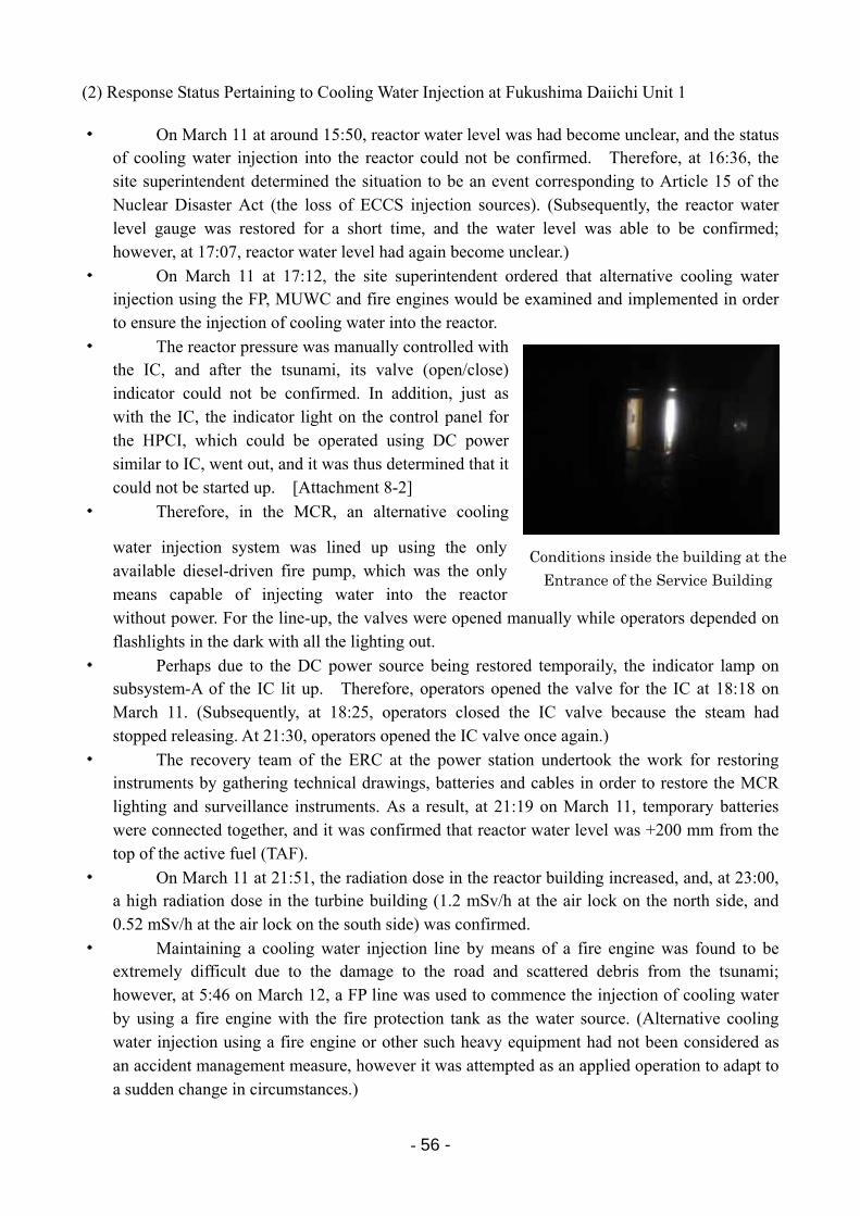
- 56 -
Conditions inside the building at the
Entrance of the Service Building
(2) Response Status Pertaining to Cooling Water Injection at Fukushima Daiichi Unit 1 ・ On March 11 at around 15:50, reactor water level was had become unclear, and the status
of cooling water injection into the reactor could not be confirmed. Therefore, at 16:36, the site superintendent determined the situation to be an event corresponding to Article 15 of the Nuclear Disaster Act (the loss of ECCS injection sources). (Subsequently, the reactor water level gauge was restored for a short time, and the water level was able to be confirmed; however, at 17:07, reactor water level had again become unclear.)
・ On March 11 at 17:12, the site superintendent ordered that alternative cooling water injection using the FP, MUWC and fire engines would be examined and implemented in order to ensure the injection of cooling water into the reactor.
・ The reactor pressure was manually controlled with the IC, and after the tsunami, its valve (open/close) indicator could not be confirmed. In addition, just as with the IC, the indicator light on the control panel for the HPCI, which could be operated using DC power similar to IC, went out, and it was thus determined that it could not be started up. [Attachment 8-2]
・ Therefore, in the MCR, an alternative cooling
water injection system was lined up using the only available diesel-driven fire pump, which was the only means capable of injecting water into the reactor without power. For the line-up, the valves were opened manually while operators depended on flashlights in the dark with all the lighting out.
・ Perhaps due to the DC power source being restored temporaily, the indicator lamp on subsystem-A of the IC lit up. Therefore, operators opened the valve for the IC at 18:18 on March 11. (Subsequently, at 18:25, operators closed the IC valve because the steam had stopped releasing. At 21:30, operators opened the IC valve once again.)
・ The recovery team of the ERC at the power station undertook the work for restoring instruments by gathering technical drawings, batteries and cables in order to restore the MCR lighting and surveillance instruments. As a result, at 21:19 on March 11, temporary batteries were connected together, and it was confirmed that reactor water level was +200 mm from the top of the active fuel (TAF).
・ On March 11 at 21:51, the radiation dose in the reactor building increased, and, at 23:00, a high radiation dose in the turbine building (1.2 mSv/h at the air lock on the north side, and 0.52 mSv/h at the air lock on the south side) was confirmed.
・ Maintaining a cooling water injection line by means of a fire engine was found to be extremely difficult due to the damage to the road and scattered debris from the tsunami; however, at 5:46 on March 12, a FP line was used to commence the injection of cooling water by using a fire engine with the fire protection tank as the water source. (Alternative cooling water injection using a fire engine or other such heavy equipment had not been considered as an accident management measure, however it was attempted as an applied operation to adapt to a sudden change in circumstances.)
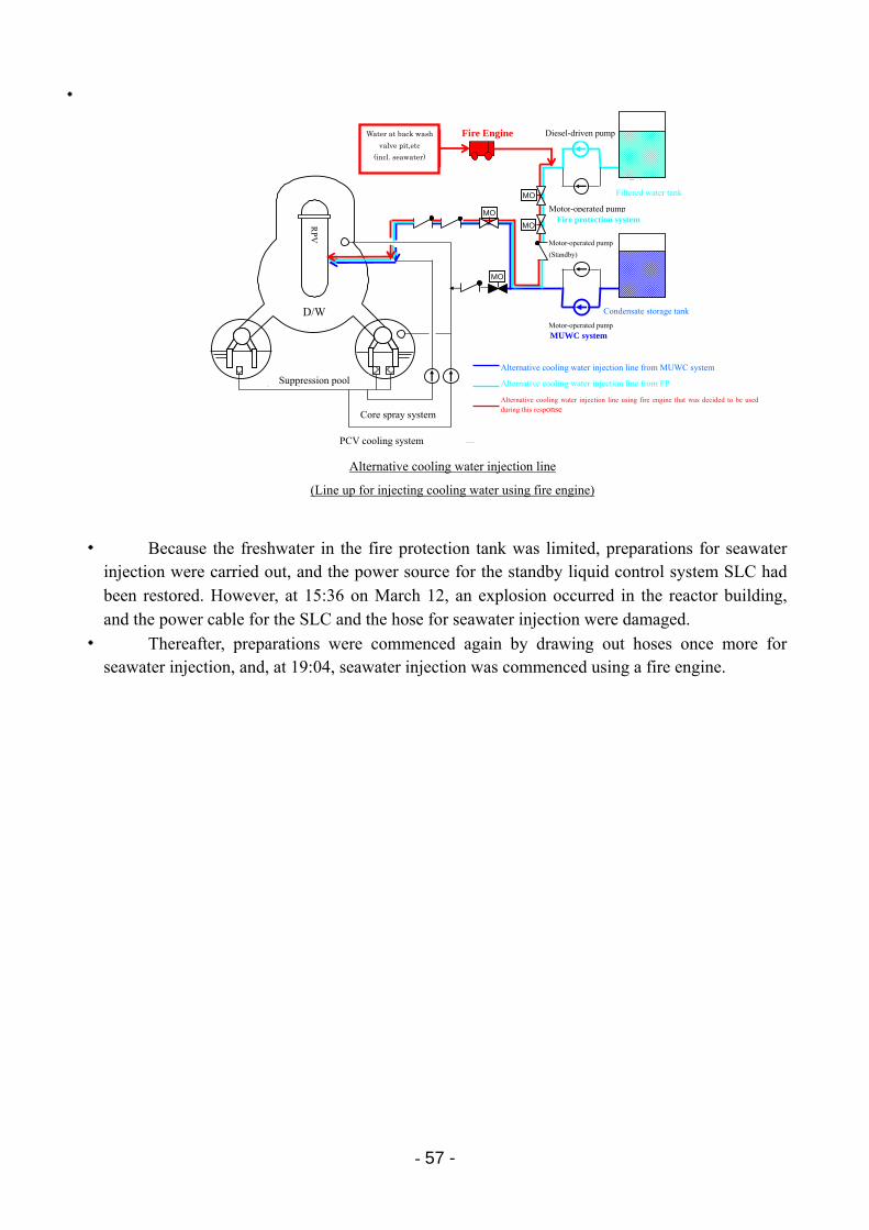
- 57 -
・
・ Because the freshwater in the fire protection tank was limited, preparations for seawater injection were carried out, and the power source for the standby liquid control system SLC had been restored. However, at 15:36 on March 12, an explosion occurred in the reactor building, and the power cable for the SLC and the hose for seawater injection were damaged.
・ Thereafter, preparations were commenced again by drawing out hoses once more for seawater injection, and, at 19:04, seawater injection was commenced using a fire engine.
Alternative cooling water injection line
(Line up for injecting cooling water using fire engine)
ろ過水タンクろ過水タンク
復水貯蔵タンク復水貯蔵タンク
消火系消火系
電動ポンプ
ディーゼル駆動ポンプ
電動ポンプ(待機)
電動ポンプ
復水補給水系復水補給水系
炉心スプレイ系
格納容器冷却系
圧力容器
ドライウェル
サプレッションプール
MO
MO
MO
MO
消防車水源水源逆先弁ピット逆先弁ピット等等(海水含む)(海水含む)
復水補給水系からの代替注水ライン
消火系からの代替注水ライン
今回の対応の中で、使用することとした消防車を使用しての代替注水ライン
D/W
Core spray system
PCV cooling system
Suppression pool
Motor-operated pump
(Standby)
Diesel-driven pump
MUWC system
RP
V
Alternative cooling water injection line using fire engine that was decided to be used during this response
Water at back wash
valve pit,etc
(incl. seawater)
Fire Engine
Alternative cooling water injection line from MUWC system
Alternative cooling water injection line from FP
Filtered water tank
Fire protection system Motor-operated pump
Condensate storage tank
Motor-operated pump
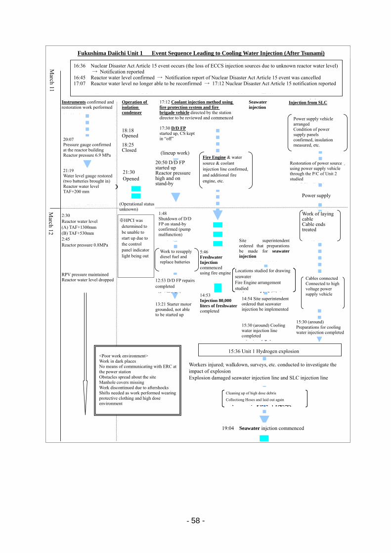
- 58 -
福島第一1号機 注水に関する主な経緯(津波襲来以降)
3月11日
12日
非常用復水器(IC)操作
16:36 原災法15条事象発生(原子炉水位不明のため、非常用炉心冷却装置注水不能)→16:45 通報
16:45 原子炉水位を確認 →16:55 原災法15条事象の解除を通報17:07 原子炉水位を再度確認できなくなる →17:12 原災法15条通報
2:45炉圧0.8MPa
炉圧一定原子炉水位低下
14:538万㍑淡水注入完了
15:36 1号機水素爆発
ホウ酸水(SLC)注入
2:30原子炉水位(A)+1300mm(B)+530mm
計器類の確認・復旧作業
21:19水位計復旧(バッテリー2個持込)炉水位
TAF+200mm
17:12消火系及び消防車を使用した注水方法の検討開始を所長が指示
18:18開操作
18:25閉操作
21:30開操作
(動作状況不明)
20:50 D/D FP起動炉圧高く待機状態
20:07現場圧力計確認炉圧 6.9MPa (ラインナップ作業)
軽油補給・バッテリー交換作業
5:46消防車による淡水注入開始
消防車・水源・注水ラインの確認、消防車の追加手配等)
14:54所長が海水注入の実施を指示
・線量の高い瓦礫の片づけ・ホースの収集・再敷設・線量の高い瓦礫の片づけ・ホースの収集・再敷設
・電源車手配
電源車到着
・電源盤の状況確認、絶縁測定等
15:30頃注水ライン完了
・ケーブル敷設作業・ケーブル端末処理
19:04 海水注入開始
15:30頃 注入準備作業完了
海水注入
17:30 D/D FP起動、CS「切」保持
・海水取水場所検討・消防車配置検討・ホース引き回し
・海水取水場所検討・消防車配置検討・ホース引き回し
・ケーブルつなぎこみ・高圧電源車へ接続
所長が海水注入の準備を指示
けが人発生、爆発の影響調査のためのサーベイ・現場確認等を実施爆発により海水注入ライン及びSLC注入ラインに損傷
※高圧注
水系は、制御盤の表示灯が消灯したため、起動不能と判断
12:53 D/D FP 修理完了
13:21 セルモータ地絡、起動不可
2号機のP/Cを介して電源車により電源復旧検討
<劣悪な作業環境>・暗所作業・緊対室との通信手段なし・障害物散乱・マンホール蓋欠落・余震による作業の中断・線量が高く、防護服を着た作業で、交替が必要
1:48待機中のD/D FP停止確認(ポンプ不調)
2:30 Reactor water level (A) TAF+1300mm (B) TAF+530mm 2:45 Reactor pressure 0.8MPa
RPV pressure maintained Reactor water level dropped
21:19 Water level gauge restored (two batteries brought in) Reactor water level TAF+200 mm
Workers injured; walkdown, surveys, etc. conducted to investigate the impact of explosion Explosion damaged seawater injection line and SLC injection line
16:36 Nuclear Disaster Act Article 15 event occurs (the loss of ECCS injection sources due to unknown reactor water level)→ Notification reported
16:45 Reactor water level confirmed → Notification report of Nuclear Disaster Act Article 15 event was cancelled 17:07 Reactor water level no longer able to be reconfirmed → 17:12 Nuclear Disaster Act Article 15 notification reported
Fukushima Daiichi Unit 1 Event Sequence Leading to Cooling Water Injection (After Tsunami)
15:36 Unit 1 Hydrogen explosion
Cleaning up of high dose debris
Collectiong Hoses and laid out again
Fire Engine & water source & coolant injection line confirmed, and additional fire engine, etc.
Power supply vehicle arranged Condition of power supply panels confirmed, insulation measured, etc.
Seawater injection
Injection from SLC
Operation of isolation condenser
17:12 Coolant injection method using fire protection system and fire brigade vehicle directed by the station director to be reviewed and commenced
18:18 Opened 18:25 Closed
Instruments confirmed and restoration work performed
20:07 Pressure gauge confirmed at the reactor building Reactor pressure 6.9 MPa
17:30 D/D FP started up, CS kept in “off”
20:50 D/D FP started up Reactor pressure high and on stand-by
21:30 Opened
Restoration of power source using power supply vehicle through the P/C of Unit 2 studied
Power supply
Work of laying cable Cable ends treated
Cables connected Connected to high voltage power supply vehicle
Site superintendent ordered that preparations be made for seawater injection
Locations studied for drawing seawater Fire Engine arrangement studied
1:48 Shutdown of D/D FP on stand-by confirmed (pump malfunction)
※HPCI was determined to be unable to start up due to the control panel indicator light being out
13:21 Starter motor grounded, not able to be started up
14:53 Injection 80,000 liters of freshwater completed
5:46 Freshwater Injection commenced using fire engine
Work to resupply diesel fuel and replace batteries
12:53 D/D FP repairs completed
14:54 Site superintendent ordered that seawater injection be implemented
15:30 (around) Cooling water injection line completed
15:30 (around) Preparations for cooling water injection completed
19:04 Seawater injction commenced
(Operational status unknown) M
arch 12 M
arch 11
(lineup work)
<Poor work environment> Work in dark places No means of communicating with ERC at the power station Obstacles spread about the site Manhole covers missing Work discontinued due to aftershocks Shifts needed as work performed wearing protective clothing and high dose environment
- 59 -
(3) Response Status Pertaining to Venting of PCV at Fukushima Daiichi Unit 1 [Attachment 8-3] ・ Due to the station black out, which resulted from the impact of the tsunami, the PCV
cooling systems (subsystem-A and -B), which had cooled the S/C in the torus cooling mode, and the SGTS shut down. Furthermore, due to loss of the instruments’ power, the status of D/W pressure became unknown.
・ On March 11 in the evening, while the instruments were being restored, the accident management operating procedures were being confirmed in the MCR. The PCV venting valves and their location by using the valve checklist were confirmed in order to proceed with preparations for the PCV venting at an early stage.
・ The operation team at the ERC at the power station also started to review PCV venting operation procedures under condition of no power, and in order to confirm valve models and structures as well as manual operability for the venting operation. Workers entered the main administration building, to which entry had been prohibited due to the earthquake, while the aftershocks were continuing. Finally they confirmed that the bypass valve of the air-operated valves could be opened with a handle.
・ On March 11 at around 23:50, when the restoration team of the ERC at the power station connected a small generator, which had been temporarily restored the MCR lighting, to the D/W pressure instrument to confirm the indicated value in the MCR, it was confirmed to be 600 kPa[abs], and this was reported to the ERC at the power station.
・ Upon receipt of this report at 0:06 on March 12, the site superintendent ordered that preparations be advanced for venting the PCV.
・ On March 12 at around 1:30, the central government was notified of the implemention of venting, and it was accepted.
・ On March 12 at 2:24, the assessment results of the venting operation time in the reactor building were reported to the ERC at the power station. It was reported that if the reactor building radiation dose were 300 mSv/h, there would be a work time of 17 minutes at the dose limit for an emergency (100mSv/h).
・ On March 12 at around 3:45, at the ERC at the Headquarters, an assessment was prepared of the radiation dose in the surrounding area during venting and shared with the power station.
・ In the MCR, in preparation for the venting operation, the order of the valve operation, the line-up of valves in the torus room, the location of the valves and other details were repeatedly confirmed.
・ On March 12 at 9:02, evacuations from Okuma Town (part of the Kuma District) were comfirmed as being completed.
・ On March 12 at 9:04, operators headed into the reactor building for venting, and at around 9:15, the motor-operated valve was opened 25% in accordance with the procedures.
・ Subsequently, operators tried to open the air-operated valve on the basement floor of the reactor building. However, the radiation dose in the reactor building was high; therefore, the venting operation could not be conducted. Accordingly, a temporary air compressor was procured, and after the comfirmination of connections, the temporary air compressor was set up and started. At 14:30, a pressure drop in the D/W was confirmed, and it was deemed that there would be a “release of radioactive material” by venting. [Attachment 8-4]
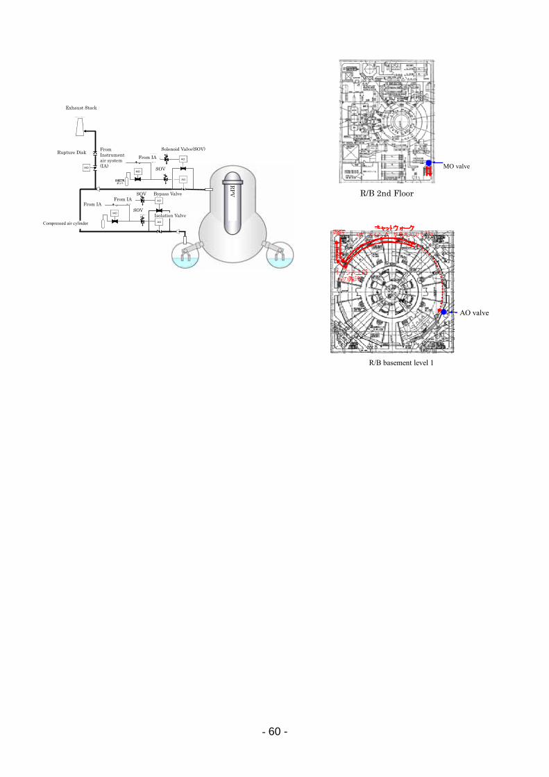
- 60 -
R/B basement level 1
R/B 2nd level
MO valve
AO valve
MO
AO
圧縮空気ボンベ
電磁弁
MO
圧縮空気ボンベ
計装用圧縮空気系より
排気筒
大弁
小弁
ラプチャーディスク
電磁弁
AO
AO
MO 電磁弁
電磁弁
AO
計装用圧縮空気系より
計装用圧縮空気系より
計装用圧縮空気系より
MO
AO
圧縮空気ボンベ
電磁弁
MO
圧縮空気ボンベ
計装用圧縮空気系より
排気筒
大弁
小弁
ラプチャーディスク
電磁弁
AO
AO
MO 電磁弁
電磁弁
AO
計装用圧縮空気系より
計装用圧縮空気系より
計装用圧縮空気系より
RP
V
Rupture Disk
Exhaust Stack
Solenoid Valve(SOV) From Instrument air system (IA)
From IA
From IA From IA
SOV
SOV
SOV
Bypass Valve
Isolation Valve
Compressed air cylinder
R/B 2nd Floor
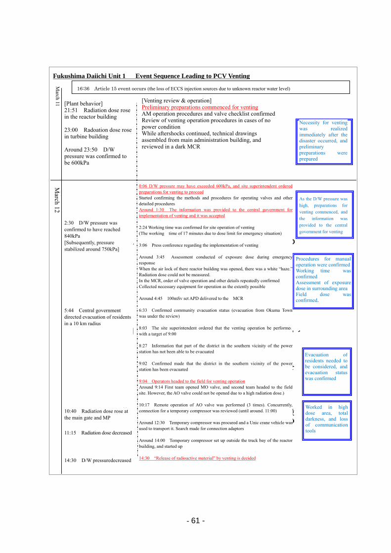
- 61 -
福島第一1号機 格納容器ベントに至る主な経緯
3月11日
12日
16:36 15条事象発生(非常用炉心冷却装置注水不能)
【ベントの検討・操作】
ベントに向けた事前準備を開始
・AM操作手順書、バルブチェックリストの確認
・電源がない場合のベント操作手順の検討
・余震が続く中、事務本館での図面収集、暗い
中央制御室での検討
21:51 原子炉建屋の線量上昇
23:00 タービン建屋の線量上昇
23:50頃 D/W圧力が600kPaであることを確認
【プラント挙動】
0:06 D/W圧力が600kPaを超えている可能性がありベントの準備を進めるよう発電所長指示
弁の操作方法や手順など具体的な手順の確
認を開始
1:30頃ベントの実施を国に申し入れ・了解
2:24 ベントの現場操作に関する作業時間の確認
(緊急時対応の線量限度で17分の作業時間)3:06 ベント実施に関するプレス会見
3:45頃ベント時の周辺被ばく線量評価を実施
2:30 D/W圧力が840kPaに到達したことを確認
・原子炉建屋二重扉を開けたら白い“もや
もや”。線量測定できず
・中央制御室では、弁の操作の順番等を、
繰り返し確認。
作業に必要な装備を可能な限り収集。
4:45頃 100mSvセットのAPDが中央制御室に届く
6:33 地域の避難状況確認(大熊町から移動を検討中)
8:03 ベント操作を9:00目標で行うよう発電所長指示8:27 発電所南側近傍の一部の地区が避難できてい
ないとの情報
9:02 発電所南側近傍の地区が避難できていることを確認
9:04 ベントの操作を行うため運転員が現場へ出発
(9:15頃に第1班がMO弁開、第2班が現場へ向かうが線量が高くAO弁は開できず)
10:17~ AO弁の遠隔操作実施(3回)。並行して仮設コンプレッサーの接続箇所検討(11:00頃まで)
12:30頃 仮設コンプレッサー確保、ユニック車を用い
て移動。接続用アダプタの捜索
14:00頃 仮設コンプレッサーを原子炉建屋大物搬入
口外に設置・起動
14:30 ベントによる「放射性物質の放出」と判断
10:40 正門、MPの線量上昇
11:15 線量が低下
14:30 D/W圧力低下
発災直後から
ベントの必要性
を認識し、事前
準備
その後、 750kPa前後で、圧力安定
D/W圧力が高まったためベントの準備を開始し、ベントを国に申し入れ
手動での手順の確認作業時間の確認周辺被ばく線量の評価現場の線量確認
住民避難を考慮する必要があり、避難状況を確認
高線量、暗闇、通信機能を喪失した中での作業
5:44 国が半径10km圏内の住民に避難指示
Fukushima Daiichi Unit 1 Event Sequence Leading to PCV Venting
16:36 Article 15 event occurs (the loss of ECCS injection sources due to unknown reactor water level)
[Plant behavior] 21:51 Radiation dose rose in the reactor building 23:00 Radoation dose rose in turbine building Around 23:50 D/W pressure was confirmed to be 600kPa
2:30 D/W pressure was confirmed to have reached 840kPa [Subsequently, pressure stabilized around 750kPa]
5:44 Central government directed evacuation of residents in a 10 km radius
10:40 Radiation dose rose at the main gate and MP
11:15 Radiation dose decreased
14:30 D/W pressuredecreased
0:06 D/W pressure may have exceeded 600kPa, and site superintendent ordered preparations for venting to proceed Started confirming the methods and procedures for operating valves and other detailed procedures Around 1:30 The information was provided to the central government for implementation of venting and it was accepted 2:24 Working time was confirmed for site operation of venting (The working time of 17 minutes due to dose limit for emergency situation) 3:06 Press conference regarding the implementation of venting Around 3:45 Assessment conducted of exposure dose during emergency response When the air lock of there reactor building was opened, there was a white “haze.” Radiation dose could not be measured. In the MCR, order of valve operation and other details repeatedly confirmed Collected necessary equipment for operation as the extently possible Around 4:45 100mSv set APD delivered to the MCR 6:33 Confirmed community evacuation status (evacuation from Okuma Town was under the review) 8:03 The site superintendent ordered that the venting operation be performed with a target of 9:00 8:27 Information that part of the district in the southern vicinity of the power station has not been able to be evacuated 9:02 Confirmed made that the district in the southern vicinity of the power station has been evacuated 9:04 Operators headed to the field for venting operation Around 9:14 First team opened MO valve, and second team headed to the field site. However, the AO valve could not be opened due to a high radiation dose.) 10:17 Remote operation of AO valve was performed (3 times). Concurrently, connection for a temporary compressor was reviewed (until around. 11:00) Around 12:30 Temporary compressor was procured and a Unic crane vehicle was used to transport it. Search made for connection adaptors Around 14:00 Temporary compressor set up outside the truck bay of the reactor building, and started up 14:30 “Release of radioactive material” by venting is decided
As the D/W pressure was
high, preparations for
venting commenced, and
the information was
provided to the central
government for venting
Procedures for manual operation were confirmedWorking time was confirmed Assessment of exposure dose in surrounding areaField dose was confirmed.
Evacuation of residents needed to be considered, and evacuation status was confirmed
Worked in high dose area, total darkness, and loss of communicationtools
Necessity for venting was realized immediately after the disaster occurred, and preliminary preparations were prepared
[Venting review & operation]Preliminary preparations commenced for venting AM operation procedures and valve checklist confirmedReview of venting operation procedures in cases of no power condition While aftershocks continued, technical drawings assembled from main administration building, and reviewed in a dark MCR
March 11
March 12
- 62 -
8.2 Response Status at Fukushima Daiichi Unit 2 (1) Course of Principal Accident Responses
・ An earthquake struck Unit 2 at 14:46 on March 11. The reactor automatically shut down, and all control rods were inserted. Thereafter, while the pressure was controlled by the SRV and reactor water level and pressure were being stabilized by manually starting up the RCIC and other efforts for the shutdown operation, tsunamis arrived before and after 15:30.
・ The tsunami lead to the failure of all DC and AC power sources, and caused the failure of the emergency seawater system needed for cooling the equipment. In addition, the response operation was conducted in a severe condition, in which floating debris from the tsunami became an obstacle to traffic, and communication measures were almost non-existent, in addition to other difficult conditions.
・ After the tsunami, reactor water level could no longer be monitored, and at 21:50 on March 11, the enabling reactor water level was able to be monitored after temporary batteries were connected. After that, reactor water level was confirmed at TAP (top of active fuel) + 3400mm.
・ In addition, the operation condition of the RCIC could not be confirmed due to loss of power. However at 2:55 on March 12, the operation of the RCIC was confirmed in the reactor building.
・ On March 12 from 4:20 to 5:00, a decrease in the water level of the condensate storage tank was confirmed. For the purpose of maitaining water level in the condensate storage tank and limiting a rise in water level of the S/C, the water source for the RCIC was switched from the condensate storage tank to the S/C to continue the injection of cooling water with the RCIC by manually operating valves in the reactor building.
・ On March 14 at 13:18, reactor water level drop was confirmed. This suggested that the reactor cooling function may have been lost at 13:25; therefore, the site superintendent determined that there was an event corresponding to Article 15 of the Nuclear Disaster Act (loss of reactor cooling function).
・ On March 14 at 17:17, reactor water level dropped to 0mm (top of active fuel (TAF)). Subsequently, the reactor pressure was decreased using the SRV, and the seawater injection was commenced using fire engines (the water injection from two fire engines were started up one by one at 19:54 and 19:57, respectively).
・ To lower the PCV pressure, the system lineup for a PCV venting line except the rupture disk was performed beginning at around 11:00 on March 13, at around 21:00 on March 14 and at 0:00 on March 15. However, the D/W pressure drop was not confirmed and remained high, and the effect of venting did not appear.
・ On March 15 from 6:00 to around 6:10, a large explosive sound occurred. At almost the same time, it was confirmed that the pressure indication for the S/C was 0 MPa[abs] (As described in “9. Plant Hydrogen Explosion Assessment,” the explosive sound is believed to have resulted from the explosion at Unit 4).

- 63 -
・ Meanwhile, the D/W pressure maintained at 730 kPa [abs] as of 7:20 on March 15. However, at the time of the next measurement at 11:25, the D/W pressure had decreased to 155 kPa [abs]. During this period, it is believed that gas in the PCV has been released into the atmosphere in some way. Around this time, the monitoring car reading near the main gate drastically increased.

- 64 -
2011年3月11日 14:47
14:50~14:51
15:02~15:28
15:07
第一波15:27第二波15:35
15:39
15:41
15:42
16:36
2011年3月13日 11:00
2011年3月14日 13:25
18:00頃
19:54
2011年3月15日 6:00~
6:10頃
福島第一発電所2号機 地震後の事故進展の流れ
日付 時間 原子炉制御 格納容器制御
圧力抑制室冷却開始
主蒸気逃し弁(逃がし弁機能)により原子炉圧力容器減圧操作開始
原子炉水位低下
原災法第15条該当事象(原子炉冷却機能喪失)(原子炉水位低下→原子炉隔離時冷却系の機能が喪失していると判断)
原子炉隔離時冷却系手動起動↓
原子炉水位L-8にて自動停止
地震による原子炉スクラム信号発信
津 波 襲 来
大きな衝撃音が発生(ほぼ同時期に圧力抑制室圧力がゼロとなる)
原災法第10条該当事象(全交流電源喪失:SBO)と判断
・SBOにより格納容器除熱 機能喪失
・原子炉自動停止(自動スクラム)・タービン・発電機停止・主蒸気隔離弁閉止・外部電源喪失・非常用ディーゼル発電機自動起動
・直流電源喪失
原子炉隔離時冷却系手動起動
消防車による海水注入開始
格納容器ベントライン構成完了
・3月14日 11:01 3号機爆発の影響でS/C ベントライン大弁が閉・3月14日 18:35頃~ S/Cベントライン,D/W ベントライン構成を順次継続
↓
・S/C側圧力は,ラプチャー ディスク作動圧力より低く 推移。一方,D/W圧力は, 設計上の最高使用圧力を 超えたが,減圧しきれない 状況を確認
非常用ディーゼル発電機A,Bトリップ → 全交流電源喪失
原子炉隔離時冷却系手動起動↓
原子炉水位L-8にて自動停止
原災法第15条該当事象(非常用炉心冷却装置注水不能と判断)
March 11, 2011
March 13, 2011
March 14, 2011
Around 6:00 to around 6:10
March 15, 2011
Course of Accident Progression after Earthquake at Fukushima Daiichi Unit 2
First wave
Second wave
Determined to be an event corresponding to Article 10 of the Nuclear Disaster Act (Station Black Out)
RCIC was manually started up
↓
Automatically shut down at reactor water level L-8
RCIC manually started up
↓
Automatically shut down at reactor water level L-8
Reactor automatically shut down (automatic scram)
Turbine & generator shut down
MSIV closed
Off-site power source was lost
EDG automatically started up
S/C cooling commenced
On March 14, at 11:01 Impact of Unit 3 explosion closed S/C venting line isolation valve March 14, from around 18:35 S/C venting line and D/W venting line configuration gradually continued S/C side pressure was maintained lower than pressure to rupture the rupture disk. At the same time, D/W pressure exceeded maximum oprating pressure, however, a condition is confirmed which is not able to be depressurized. Operation commenced to depressurize the RPV using
SRV(relief valve function)
Event corresponding to Article 15 of the Nuclear Disaster Act (loss of reactor
cooling function)
(Reactor water level decreased →Determined that function of the RCIC was lost)
Large explosive sound occurred (at almost the same time, the S/C pressure became zero)
PCV venting line up was completed
DC power sources were lost
RCIC was manually started up
Date PCV control Time RPV control
Reactor scram signal transmitted due to earthquake
Tsunami arrival
Reactor water level dropped
Seawater injection commenced using fire engine
Determined to be an event corresponding to Article 15 of the Nuclear Disaster Act (the loss of ECCS injection sources)
EDG A and B tripped → Station black out
SBO causes loss of function for removing residual heat from PCV
Around 18:00
- 65 -
(2) Response Status for Cooling Water Injection at Fukushima Daiichi Unit 2
・ On March 11 at around 15:50, the instrumentation power source was lost, and reactor water level became unknown. Consequently, reactor water level could not be confirmed, and the cooling water injection into the reactor including the ECCS was unknown; therefore, the site superintendent determined at 16:36 that the situation was an event corresponding to Article 15 of the Nuclear Disaster Act (the loss of ECCS injection function).
・ Reactor water level continued to be unknown, and the cooling water injection into the reactor by measure of the RCIC could not be confirmed either, therefore, at 21:02 on March 11, TEPCO reported to the government agencies and other such institutions that reactor water level might decrease down the top of active fuel (TAF). Furthermore, the time at which TAF was reached was assessed to be 21:40.
・ After restoring instruments, at 21:50 on March 11, reactor water level was confirmed at TAF+3400mm. Furthermore, at around 3:00 on March 12, operators confirmed in the reactor building that the pump discharge pressure on the RCIC was high enough, indicating its opearation.
・ As it was confirmed that part of the Unit 2 power center was usable, restoration proceeded on the power source for the control rod drive system pump and the SLC pump, both of which having the capability to inject cooling water at high pressure. However due to the explosion at Unit 1 at 15:36 on March 12, the cable, which had been temporary laid out, was damaged, and the high-voltage power source car shut down.
・ On March 13 at 12:05, the site superintendent (director of the ERC at the power station) ordered that preparations be started for injecting seawater into the reactor in case of a shut down of the RCIC.
・ On March 14 at 11:01, the explosion at Unit 3 damaged the hose and fire engine of the seawater injection line, for which preparations had been completed, and they were rendered unusable.
・ Subsequently, due to the scattered debris, it was decided that the water source was changed from the Unit 3 back wash valve pit to the unloading wharf, which was initially considered.
・ The cooling water injection into the reactor was undertaken using the RCIC, however, at 13:18 on March 14, reactor water level showed a declining trend, and the site superintendent determined at 13:25 that there was an event corresponding to Article 15 of the Nuclear Disaster Act (loss of reactor cooling function).
・ In order to inject cooling water into the reactor using a fire engine, depressurization of the reactor was necessary by the measure of the SRV as the discharge pressure of the fire engine was low. However, because there was the possibility that the pressure and temperature of the S/C, which would be the release destination of steam in the reactor, were both high; and that depressurization would be difficult. Although it was decided to perform depressurization after undertaking the preparations for the PCV venting, the air pressure for the air-operated vent valve was not adequate, and it was decided to prioritize depressurization by measure of the SRV.
・ As batteries were needed to open the SRV, batteries were collected from staff members’ vehicles, carried to the MCR and connected. However, the valve did not operate as expected,
- 66 -
therefore, the connecting positions of the batteries were changed along with other sorts of responses to perform the depressurization.
・ As the temperature and pressure of the S/C were high, and the steam from the reactor did not easily condense, a certain amount of time was required for depressurization, even after the operation to open the SRV.
・ Meanwhile, in regard to the fire engine needed for injecting cooling water, at 16:30 on March 14, the fire engine was started up, so that seawater could be injected when the reactor was depressurized. However, at 19:20 on March 14, it was confirmed that the fire eingine, which had been started up, shut down due to lack of fuel. Subsequently, the fire engines were started up (the water injection from two fire engines started up one by one at 19:54 and 19:57, respectively), and the seawater injection was commenced into the reactor through the FP line.
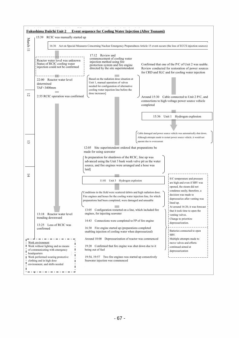
- 67 -
福島第一2号機 注水に関する主な経緯(津波襲来以降)
3月11日
16:36 原子力災害対策特別措置法15条事象発生(非常用炉心冷却装置注水不能)
作業環境・照明、緊対室との通信手段がない中での作業・線量が高く、防護服を着た作業でかつ、交替が必要
22:00 炉水位判明TAF+3400mm
2:55 RCIC運転確認
13:25 RCIC機能喪失を判断
12日
ケーブル損傷、電源車自動停止。電源車の再起動を試みるも過電流で動作せず
13:05 消防車を含む海水注入のライン構成を再開
14日
14:43 消防車のFPへの接続完了
11:01 3号機水素爆発
現場は瓦礫が散乱、線量が高い状態。準備が完了していた注水ラインは消防車・ホースが破損・使用不可
19:20 消防車が燃料切れで停止していることを確認
19:54、19:57 各1台消防車起動海水注入開始
1号機の線量の状況を踏まえ、線量が高くなる前に代替注水ラインの構成に必要な弁を手動操作
15:39 RCIC手動起動
原子炉水位不明
RCIC注水状況確認できず
12:05 海水を使用する準備を進めるよう所長指示
15:30頃 2号機P/Cへのケーブルつなぎこみ、高圧電源車への接続完了
13日
15:36 1号機水素爆発
RCICの停止に備え3号機逆洗弁ピットを水源としたライン構成を進め、消防車配置・ホース敷設を実施
13:18 炉水位低下傾向
16:30 消防車起動(減圧時に注水できる準備完了)
18:00頃 原子炉減圧開始
2号機のP/Cの1つが使用可能であることを確認。CRD、SLCの電源復旧・注入を検討
17:12消火系及び消防車を使用した注水方法の検討開始を所長が指示
S/C温度・圧力が高く、SRVを開しても蒸気が凝縮しにくいため、ベントのラインナップ後に減圧することを決定。16:20頃、ベント弁開に時間がかかる見通し判明。減圧優先に変更。
SRV開のためバッテリーを接続。複数の弁の動作を試みて減圧に向けた努力を継続
Fukushima Daiichi Unit 2 Event sequence for Cooling Water Injection (After Tsunami)
16:36 Act on Special Measures Concerning Nuclear Emergency Preparedness Article 15 event occurs (the loss of ECCS injection sources)
15:39 RCIC was manually started up
Reactor water level was unknown Status of RCIC cooling water injection could not be confirmed
17:12 Review and commencement of cooling water injection method using fire protection system and fire engine directed by the site superintendent
Confirmed that one of the P/C of Unit 2 was usable. Review conducted for restoration of power sources for CRD and SLC and for cooling water injection
Around 15:30 Cable connected to Unit 2 P/C, and connections to high-voltage power source vehicle completed
Based on the radiation dose situation at Unit 1, manual operation of valves needed for configuration of alternative cooling water injection line before the dose increases]
22:00 Reactor water level determined TAF+3400mm
2:55 RCIC operation was confirmed
Cable damaged and power source vehicle was automatically shut down.
Although attempts made to restart power source vehicle, it would not
operate due to overcurrent
12:05 Site superintendent ordered that preparations be made for using seawater
In preparation for shutdown of the RCIC, line up was advanced using the Unit 3 bask wash valve pit as the water source, and fire engines were arranged and a hose was laid]
Work environment Work without lighting and no means of communicating with emergency headquarters Work performed wearing protective clothing and in high dose environment, and shifts needed
S/C temperature and pressure
are high and even if SRV was
opened, the steam did not
condense easily, therefore, a
decision was made to
depressurize after venting was
lined up.
At around 16:20, it was forecast
that it took time to open the
venting valves.
Change to prioritize
depressurization.
Batteries connected to open
SRV.
Multiple attempts made to
move valves and efforts
continued aimed at
depressurization
11:01 Unit 3 Hydrogen explosion
15:36 Unit 1 Hydrogen explosion
Conditions in the field were scattered debris and high radiation dose.
Fire engines and hoses for the cooling water injection line, for which
preparations had been completed, were damaged and unusable
13:18 Reactor water level trending downward 13:25 Loss of RCIC was confirmed
13:05 Configuration restarted on a line, which included fire engines, for injecting seawater 14:43 Connections were completed to FP of fire engine 16:30 Fire engine started up (preparations completed enabling injection of cooling water when depressurized) Around 18:00 Depressurization of reactor was commenced 19:20 Confirmed that fire engine was shut down due to it being out of fuel 19:54, 19:57 Two fire engines was started up consectively Seawater injection was commenced
14 13
12 M
arch 11
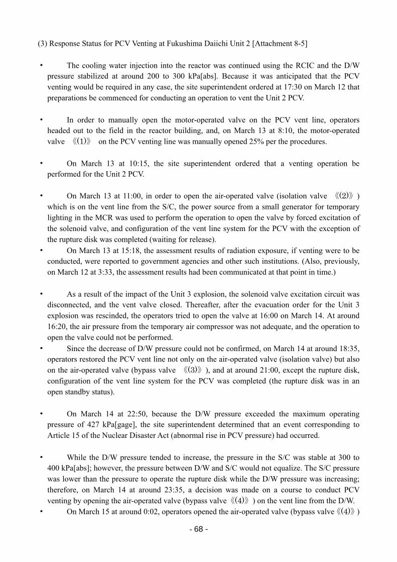
- 68 -
(3) Response Status for PCV Venting at Fukushima Daiichi Unit 2 [Attachment 8-5]
・ The cooling water injection into the reactor was continued using the RCIC and the D/W pressure stabilized at around 200 to 300 kPa[abs]. Because it was anticipated that the PCV venting would be required in any case, the site superintendent ordered at 17:30 on March 12 that preparations be commenced for conducting an operation to vent the Unit 2 PCV.
・ In order to manually open the motor-operated valve on the PCV vent line, operators headed out to the field in the reactor building, and, on March 13 at 8:10, the motor-operated valve 《(1)》 on the PCV venting line was manually opened 25% per the procedures.
・ On March 13 at 10:15, the site superintendent ordered that a venting operation be performed for the Unit 2 PCV.
・ On March 13 at 11:00, in order to open the air-operated valve (isolation valve 《(2)》) which is on the vent line from the S/C, the power source from a small generator for temporary lighting in the MCR was used to perform the operation to open the valve by forced excitation of the solenoid valve, and configuration of the vent line system for the PCV with the exception of the rupture disk was completed (waiting for release).
・ On March 13 at 15:18, the assessment results of radiation exposure, if venting were to be conducted, were reported to government agencies and other such institutions. (Also, previously, on March 12 at 3:33, the assessment results had been communicated at that point in time.)
・ As a result of the impact of the Unit 3 explosion, the solenoid valve excitation circuit was disconnected, and the vent valve closed. Thereafter, after the evacuation order for the Unit 3 explosion was rescinded, the operators tried to open the valve at 16:00 on March 14. At around 16:20, the air pressure from the temporary air compressor was not adequate, and the operation to open the valve could not be performed.
・ Since the decrease of D/W pressure could not be confirmed, on March 14 at around 18:35, operators restored the PCV vent line not only on the air-operated valve (isolation valve) but also on the air-operated valve (bypass valve 《(3)》), and at around 21:00, except the rupture disk, configuration of the vent line system for the PCV was completed (the rupture disk was in an open standby status).
・ On March 14 at 22:50, because the D/W pressure exceeded the maximum operating pressure of 427 kPa[gage], the site superintendent determined that an event corresponding to Article 15 of the Nuclear Disaster Act (abnormal rise in PCV pressure) had occurred.
・ While the D/W pressure tended to increase, the pressure in the S/C was stable at 300 to 400 kPa[abs]; however, the pressure between D/W and S/C would not equalize. The S/C pressure was lower than the pressure to operate the rupture disk while the D/W pressure was increasing; therefore, on March 14 at around 23:35, a decision was made on a course to conduct PCV venting by opening the air-operated valve (bypass valve《(4)》) on the vent line from the D/W.
・ On March 15 at around 0:02, operators opened the air-operated valve (bypass valve《(4)》)
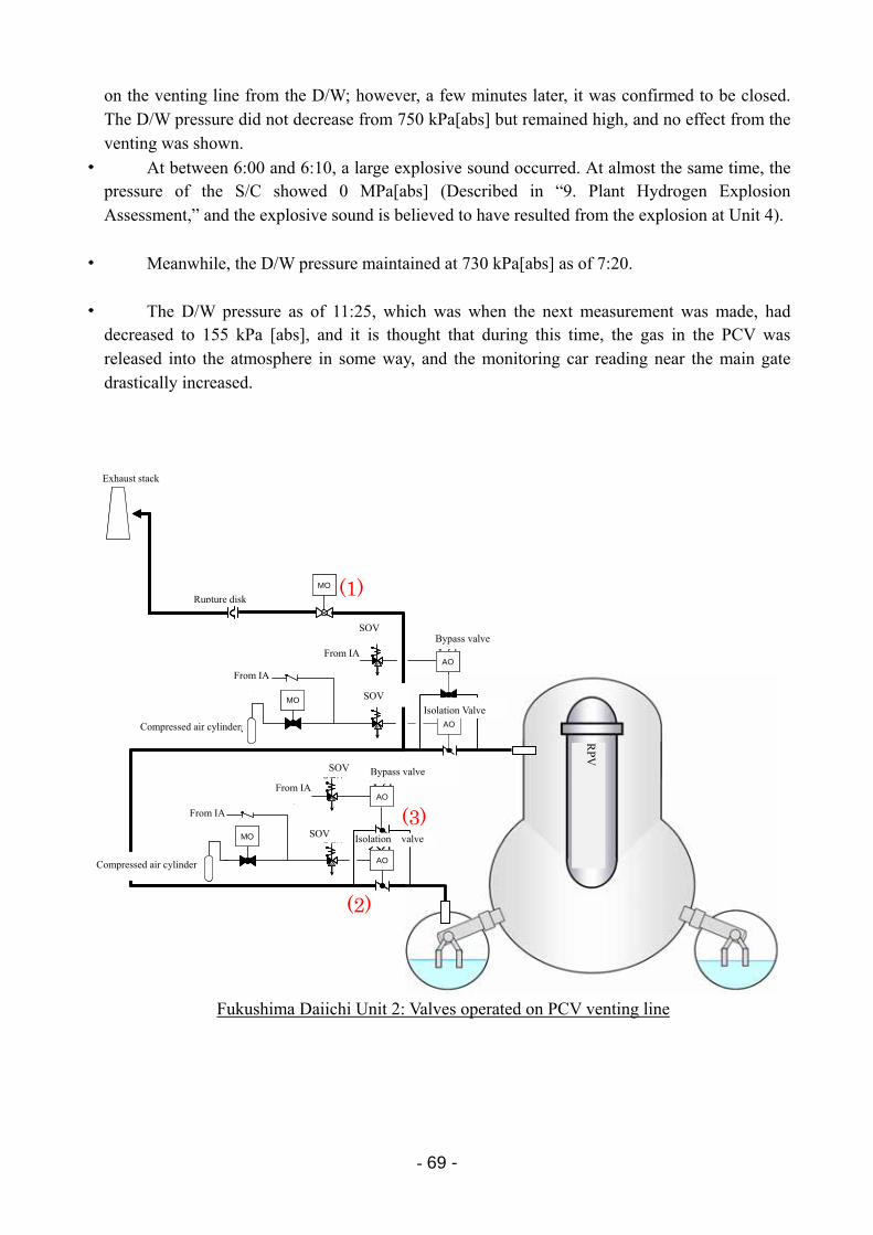
- 69 -
on the venting line from the D/W; however, a few minutes later, it was confirmed to be closed. The D/W pressure did not decrease from 750 kPa[abs] but remained high, and no effect from the venting was shown.
・ At between 6:00 and 6:10, a large explosive sound occurred. At almost the same time, the pressure of the S/C showed 0 MPa[abs] (Described in “9. Plant Hydrogen Explosion Assessment,” and the explosive sound is believed to have resulted from the explosion at Unit 4).
・ Meanwhile, the D/W pressure maintained at 730 kPa[abs] as of 7:20.
・ The D/W pressure as of 11:25, which was when the next measurement was made, had decreased to 155 kPa [abs], and it is thought that during this time, the gas in the PCV was released into the atmosphere in some way, and the monitoring car reading near the main gate drastically increased.
Fukushima Daiichi Unit 2: Valves operated on PCV venting line
圧縮空気ボンベ
電磁弁MO
圧縮空気ボンベ
計装用圧縮空気系より
ラプチャーディスク
電磁弁
MO
AO
AO
排気筒
電磁弁
電磁弁
計装用圧縮空気系より
計装用圧縮空気系より
計装用圧縮空気系より
MO
AO
AO
小弁
大弁
小弁
大弁
圧縮空気ボンベ
電磁弁MO
圧縮空気ボンベ
計装用圧縮空気系より
ラプチャーディスク
電磁弁
MO
AO
AO
排気筒
電磁弁
電磁弁
計装用圧縮空気系より
計装用圧縮空気系より
計装用圧縮空気系より
MO
AO
AO
小弁
大弁
小弁
大弁
(2)
(3)
(1)
RP
V
Exhaust stack
Rupture disk
From IA
From IA
Compressed air cylinder
From IA
From IA
Compressed air cylinder
SOV
SOV
SOV
SOV
Bypass valve
Isolation Valve
Bypass valve
Isolation valve
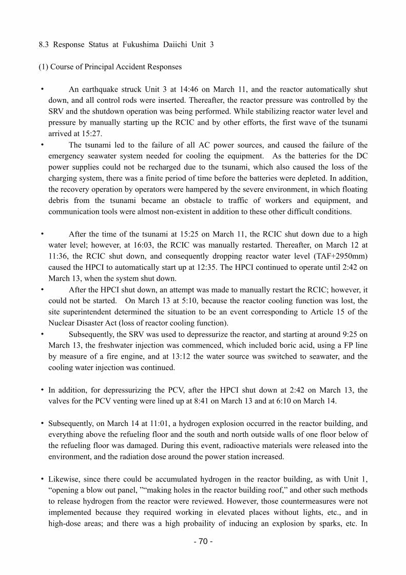
- 70 -
8.3 Response Status at Fukushima Daiichi Unit 3 (1) Course of Principal Accident Responses
・ An earthquake struck Unit 3 at 14:46 on March 11, and the reactor automatically shut down, and all control rods were inserted. Thereafter, the reactor pressure was controlled by the SRV and the shutdown operation was being performed. While stabilizing reactor water level and pressure by manually starting up the RCIC and by other efforts, the first wave of the tsunami arrived at 15:27.
・ The tsunami led to the failure of all AC power sources, and caused the failure of the emergency seawater system needed for cooling the equipment. As the batteries for the DC power supplies could not be recharged due to the tsunami, which also caused the loss of the charging system, there was a finite period of time before the batteries were depleted. In addition, the recovery operation by operators were hampered by the severe environment, in which floating debris from the tsunami became an obstacle to traffic of workers and equipment, and communication tools were almost non-existent in addition to these other difficult conditions.
・ After the time of the tsunami at 15:25 on March 11, the RCIC shut down due to a high water level; however, at 16:03, the RCIC was manually restarted. Thereafter, on March 12 at 11:36, the RCIC shut down, and consequently dropping reactor water level (TAF+2950mm) caused the HPCI to automatically start up at 12:35. The HPCI continued to operate until 2:42 on March 13, when the system shut down.
・ After the HPCI shut down, an attempt was made to manually restart the RCIC; however, it could not be started. On March 13 at 5:10, because the reactor cooling function was lost, the site superintendent determined the situation to be an event corresponding to Article 15 of the Nuclear Disaster Act (loss of reactor cooling function).
・ Subsequently, the SRV was used to depressurize the reactor, and starting at around 9:25 on March 13, the freshwater injection was commenced, which included boric acid, using a FP line by measure of a fire engine, and at 13:12 the water source was switched to seawater, and the cooling water injection was continued.
・ In addition, for depressurizing the PCV, after the HPCI shut down at 2:42 on March 13, the valves for the PCV venting were lined up at 8:41 on March 13 and at 6:10 on March 14.
・ Subsequently, on March 14 at 11:01, a hydrogen explosion occurred in the reactor building, and everything above the refueling floor and the south and north outside walls of one floor below of the refueling floor was damaged. During this event, radioactive materials were released into the environment, and the radiation dose around the power station increased.
・ Likewise, since there could be accumulated hydrogen in the reactor building, as with Unit 1, “opening a blow out panel, ”“making holes in the reactor building roof,” and other such methods to release hydrogen from the reactor were reviewed. However, those countermeasures were not implemented because they required working in elevated places without lights, etc., and in high-dose areas; and there was a high probaility of inducing an explosion by sparks, etc. In

- 71 -
addition, with respect to “making holes in the reactor building wall by the water jet,” which has a low risk of explosion, the equipment for such measures was procured, but such equipment had not arrived at the power plant before the explosion of Unit 3.
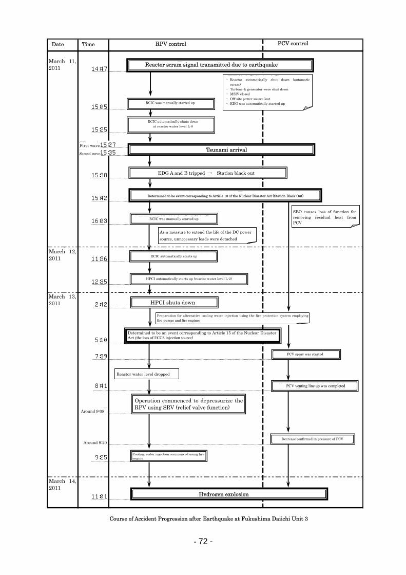
- 72 -
2011年3月11日 14:47
15:05
15:25
第一波15:27第二波15:35
15:38
15:42
16:03
2011年3月12日 11:36
12:35
2011年3月13日 2:42
5:10
7:39
8:41
9:08頃
9:20頃~
9:25
2011年3月14日
11:01
福島第一発電所3号機 地震後の事故進展の流れ
日付 時間 原子炉制御 格納容器制御
主蒸気逃し弁(逃がし弁機能)により原子炉圧力容器減圧操作開始
原子炉水位低下
原子炉隔離時冷却系手動起動
原子炉隔離時冷却系原子炉水位L-8にて自動停止
地震による原子炉スクラム信号発信
津 波 襲 来
水 素 爆 発
原災法第10条該当事象(全交流電源喪失:SBO)と判断
・SBOにより格納容器除熱 機能喪失
・原子炉自動停止(自動スクラム)・タービン・発電機停止・主蒸気隔離弁閉止・外部電源喪失・非常用ディーゼル発電機自動起動
非常用ディーゼル発電機A,Bトリップ → 全交流電源喪失
格納容器ベントライン構成完了
原子炉隔離時冷却系手動起動
・直流電源の延命策として,不必要な 負荷の切り離し実施
原子炉隔離時冷却系自動停止
高圧注水系自動起動(原子炉水位低L-2)
高圧注水系停止
・消火ポンプ,消防車による消火系を用いた 代替注水の準備
消防車による注水開始
格納容器圧力の低下確認
格納容器スプレイ開始
原災法第15条該当事象(原子炉冷却機能喪失)と判断
RPV control PCV control Time Date
Tsunami arrival
Determined to be event corresponding to Article 10 of the Nuclear Disaster Act (Station Black Out)
Determined to be an event corresponding to Article 15 of the Nuclear Disaster Act (the loss of ECCS injection source)
Hydrogen explosion
Course of Accident Progression after Earthquake at Fukushima Daiichi Unit 3
March 11, 2011
March 12, 2011
March 13, 2011
March 14, 2011
Around 9:20
Around 9:08
First wave
Second wave
SBO causes loss of function for removing residual heat from PCV
As a measure to extend the life of the DC power
source, unnecessary loads were detached
RCIC automatically shuts down at reactor water level L-8
RCIC was manually started up
EDG A and B tripped → Station black out
RCIC was manually started up
RCIC automatically starts up
HPCI automatically starts up (reactor water level L-2)
Preparation for alternative cooling water injection using the fire protection system employing fire pumps and fire engines
HPCI shuts down
Reactor water level dropped
Cooling water injection commenced using fire engine
PCV spray was started
PCV venting line up was completed
Decrease confirmed in pressure of PCV
Reactor scram signal transmitted due to earthquake
・ Reactor automatically shut down (automatic scram)
・ Turbine & generator were shut down ・ MSIV closed ・ Off-site power source lost ・ EDG was automatically started up
Operation commenced to depressurize the RPV using SRV (relief valve function)
- 73 -
(2) Response Status Pertaining to Cooling Water Injection at Fukushima Daiichi Unit 3
・ Immediately after arrival of the tsunami, the RCIC and HPCI, which are equipment operable using a DC power source, were operable, and, on March 11 at 16:03, in order to maintain reactor water level, the RCIC was manually started up, and reactor water level was maintained.
・ On March 12 at 11:36, the RCIC was shut down, and on March 12 at 12:35, the HPCI automatically started up with the reactor water low level signal (L-2: TAF+2950 mm).
・ As the HPCI shut down on March 13 at 2:42, an alternative measure of injecting cooling water was attempted using a diesel-driven fire pump; however, the reactor pressure, which had temporarily decreased, increased again to 4.1 MPa[gage], and cooling water could not be injected into the reactor.
・ Subsequently, the turbine-driven RCIC and HPCI were started up again, for injecting cooling water into the reactor. However, the HPCI could not be started up due to depleted batteries, and the RCIC could not also be started up.
・ As the cooling water injection into the reactor could not be performed using the RCIC, the site superintendent determined on March 13 at 5:10 that the situation was an event corresponding to Article 15 of the Nuclear Disaster Act (loss of reactor cooling function).
・ Meanwhile, after the site superintendent’s (director of the ERC at the power station) order at 17:12 on March 11, the ERC at the power station had been considering alternative cooling water injection methods into the reactor of the three fire engines deployed at the power station. One was being used for the seawater injection into Unit 1, and the other was unusable due to the impact of the tsunami. The fire engine had difficulty in moving to the side of Units 5 and 6 due to the damaged road on the side of Units 5 and 6.
・ Thereafter, workers proceeded to restore the road, and it became possible to go and come from the side of Units 5 and 6. Therefore, the fire engine on the side of Units 5 and 6 was delivered to the side of Units 1 to 4. In addition, a fire engine, which was standing by an emergency backup at the Fukushima Daini NPS, was delivered to the Fukushima Daiichi NPS.
・ In order to inject cooling water into the reactor using a fire engine, depressurization of the reactor was necessary by means of the SRV, as the discharge pressure of the fire engine was low. Furthermore, although a battery was necessary to open the SRV, a necessary power source could not be secured since it was after batteries had been gathered in order to restore instruments and for other purposes in Units 1 and 2, and consequently, the SRV could not be operated.
・ Workers of the ERC at the power station started removing the batteries from their personal vehicles and bringing them to the MCR to use for the SRV power source. On March 13 at 9:08, the SRV was finally manually opened, and the reactor was depressurized promptly.
・ As a result of this depressurization work, the reactor pressure dropped below the discharge pressure of the fire engine pump. On March 13 at 9:25, boric acid was dissolved into the fire protection tank (freshwater), and this cooling water injected into the reactor.

- 74 -
・ On March 13 at 12:20, as the freshwater in the fire protection tank was depleted, the system was switched for the cooling water injection source so that seawater in the backwash valve pit would be injected, and the seawater injection commenced at 13:12.
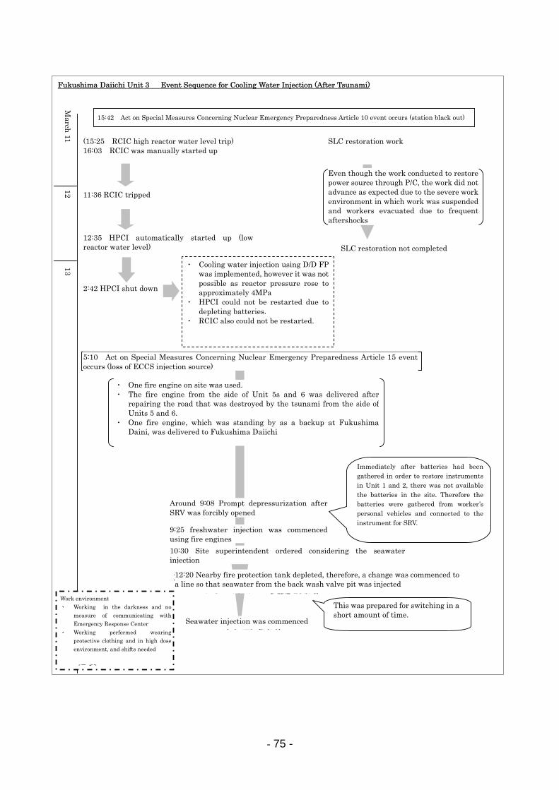
- 75 -
福島第一3号機 注水に関する主な経緯(津波襲来以降)
12日
5:10 原子力災害対策特別措置法15条事象発生(原子炉冷却機能喪失)
作業環境・照明、緊対室との通信手段がない中での作業・線量が高く、防護服を着た作業でかつ、交替が必要
13日
(15:25 RCIC原子炉水位高トリップ)16:03 RCIC手動起動
11:36 RCICトリップ
SLC復旧作業
2:42 HPCI停止
9:08頃 SRV強制開による急速減圧
12:20 近場の防火水槽が枯渇したため、逆洗弁ピットの海水を注入するようラインの変更を開始
13:12 海水注入開始
SLC復旧完了せず
・D/D FPによる注水を試みるも、炉圧が約4MPaまで上昇し注入できず・HPCIの再起動を試みるも、バッテリー枯渇のため起動できず・RCICによる原子炉注水を試みるも、起動できず
3月11日
・所内の消防車は1号機で使用。・道路損傷や津波の瓦礫の影響で5/6号機側と分断されていた道路の往来を可能にし、5/6号機側にあった消防車を回収・福島第二でバックアップとして待機していた消防車1台を福島第一へ移動
9:25 消防車による淡水注水開始
10:30 海水注入を視野に入れて動くとの発電所長指示
短時間で切り替えられるよう、あらかじめ準備していた
既に1,2号機の計器復旧のため所内のバッテリーを集めた後であり、所内にバッテリーの予備がない中、社員の通勤用自動車のバッテリーを集めて計器盤につなぎこみ
P/Cを介した電源復旧作業を実施するも、度々の余震による作業中断・避難や、劣悪な作業環境等により思うように作業が進まず
15:42 原子力災害対策特別措置法10条事象発生(全交流電源喪失)
12:35 HPCI自動起動(原子炉水位低)
Fukushima Daiichi Unit 3 Event Sequence for Cooling Water Injection (After Tsunami)
15:42 Act on Special Measures Concerning Nuclear Emergency Preparedness Article 10 event occurs (station black out)
(15:25 RCIC high reactor water level trip) 16:03 RCIC was manually started up
Even though the work conducted to restore power source through P/C, the work did not advance as expected due to the severe work environment in which work was suspended and workers evacuated due to frequent aftershocks
SLC restoration not completed
SLC restoration work
11:36 RCIC tripped
12:35 HPCI automatically started up (low reactor water level)
2:42 HPCI shut down
・ Cooling water injection using D/D FPwas implemented, however it was not possible as reactor pressure rose to approximately 4MPa
・ HPCI could not be restarted due to depleting batteries.
・ RCIC also could not be restarted.
・ One fire engine on site was used. ・ The fire engine from the side of Unit 5s and 6 was delivered after
repairing the road that was destroyed by the tsunami from the side of Units 5 and 6.
・ One fire engine, which was standing by as a backup at Fukushima Daini, was delivered to Fukushima Daiichi
Immediately after batteries had been gathered in order to restore instrumentsin Unit 1 and 2, there was not available the batteries in the site. Therefore the batteries were gathered from worker’s personal vehicles and connected to the instrument for SRV.
Work environment ・ Working in the darkness and no
measure of communicating with Emergency Response Center
・ Working performed wearing protective clothing and in high dose environment, and shifts needed
This was prepared for switching in a short amount of time.
5:10 Act on Special Measures Concerning Nuclear Emergency Preparedness Article 15 event occurs (loss of ECCS injection source)
Around 9:08 Prompt depressurization afterSRV was forcibly opened
9:25 freshwater injection was commenced using fire engines
10:30 Site superintendent ordered considering the seawater injection
12:20 Nearby fire protection tank depleted, therefore, a change was commenced to a line so that seawater from the back wash valve pit was injected
Seawater injection was commenced
13 12
March
11
- 76 -
(3) Response Status Pertaining to Venting of PCV at Fukushima Daiichi Unit 3 [Attachment 8-6]
・ On March 12 at 17:30, the site superintendent ordered the beginning of preparations for the PCV venting. (Review of the procedures and the necessary valve locations were confirmed along with other details.)
・ On March 13 at 4:50, in order to open the air-operated valve on the vent line from the S/C, the portable generator being used for temporary lighting in the MCR, was used as a power source for the solenoid valve, and it was forcibly energized.
・ On March 13 at 5:15, the site superintendent ordered to complete the vent line up except for the rupture disk.
・ When operators went to the torus room (where the S/C is installed) to confirm the valve opening condition, it was fully closed. Accordingly, beginning at 5:23 on March 13, the compressed air cylinder was replaced, and the vent valve was then able to be opened.
・ On March 13 at 5:50, a press conference was commenced regarding the implementation of PCV venting, and at 7:35, TEPCO reported to the government agencies and other such institutions the assessment results of radiation exposure to the area surrounding the power station when the PCV venting was to be implemented.
・ At around 8:35, the MO valve on the vent line from the S/C was manually opened to 15 %. <<(1)>> Standard procedures call for the vent to be opened to 25%; however, this was lowered in order to prevent excessive decrease in PCV pressure drastically.
・ At 8:41, alignment of the vent lineup, excluding the rupture disk, was completed. However, PCV pressure was too low to rupture the rupture disk. (427 kPa[gage]) Therefore, the system would not vent (waiting for rupturing the rupture disk), and the vent system alignment was kept open <<(2)>> and PCV pressure was monitored.
・ At 9:24, PCV pressure drop was verified; therefore, at approximately 9:20, it was determined that the S/C had been vented. [Attachment 8-7]
・ On March 13 at 11:17, due to decreasing pressure of the compressed air cylinder, the aforementioned air-operated valve << (2) >> was closed. Therefore, the air cylinder was replaced and the valve opened again at 12:30.
・ After that, the valve needed to be maintained to be an open; however, operators could not keep the valve open due to the difficulty of the high room temperature at the torus room.
・ On March 13 at around 17:52, workers headed to the field to set up a temporary compressor at the truck bay of the turbine building and connected it to the instrument air system. At around 21:10, as the D/W pressure decreased, it was deemed that the air-operated valve <<(2)>> on the vent line from the S/C was opened.
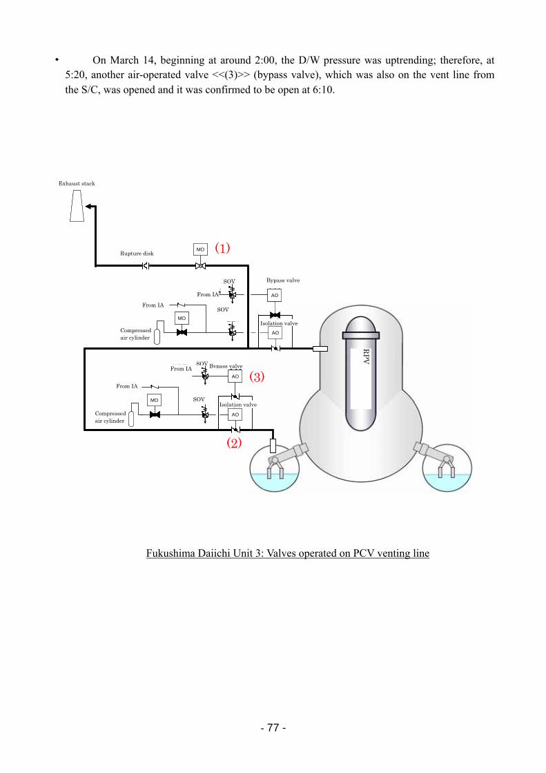
- 77 -
・ On March 14, beginning at around 2:00, the D/W pressure was uptrending; therefore, at 5:20, another air-operated valve <<(3)>> (bypass valve), which was also on the vent line from the S/C, was opened and it was confirmed to be open at 6:10.
圧縮空気ボンベ
電磁弁MO
圧縮空気ボンベ
計装用圧縮空気系より
ラプチャーディスク
電磁弁
MO
AO
AO
排気筒
電磁弁
電磁弁
計装用圧縮空気系より
計装用圧縮空気系より
計装用圧縮空気系より
MO
AO
AO
小弁
大弁
小弁
大弁
圧縮空気ボンベ
電磁弁MO
圧縮空気ボンベ
計装用圧縮空気系より
ラプチャーディスク
電磁弁
MO
AO
AO
排気筒
電磁弁
電磁弁
計装用圧縮空気系より
計装用圧縮空気系より
計装用圧縮空気系より
MO
AO
AO
小弁
大弁
小弁
大弁
(1)
(2)
(3)
Fukushima Daiichi Unit 3: Valves operated on PCV venting line
RP
V
Exhaust stack
Rupture disk
From IA
From IA
Compressed air cylinder
From IA
From IA
Compressed air cylinder
SOV
SOV
SOV
SOV
Bypass valve
Isolation valve
Bypass valve
Isolation valve
- 78 -
8.4 Response Status at Fukushima Daiichi Unit 4
・ When an earthquake stuck Unit 4 at 14:46 on March 11, Unit 4 was in outage, and all the fuel had been taken out from the reactor and put into the SFP for the shroud replacement project. A total of 1535 fuel assemblies were stored in the SFP.
・ On the first wave of the tsunami at 15:27 on March 11, all of the DC and AC power sources were lost and together with this the SFP cooling function and the makeup water function was lost.
・ On March 14 at 4:08, it was confirmed that the water temperature in the SFP was 84 degrees C.
・ On March 15 from 6:00 to around 6:10, a large sound occurred, and subsequently, damage was confirmed near the roof of the 5th floor of the reactor building.
・ Furthermore, on March 15 at 9:38, it was confirmed that a fire broke out near the northwest corner of the 3rd floor of the reactor building. However, at around 11:00, it was confirmed that the fire had extinguished naturally. In addition, on March 16 at around 5:45, a fire broke out near the northwest area of the reactor building was reported. However, this was not able to be confirmed at around 6:15.
・ The recovery condition for cooling water injection and cooling of the SFP is described in “8.9 Spent Fuel Storage Situation,” and observations regarding the explosion at the top of the reactor building are described in “9.2 Cause of Hydrogen Explosion.”
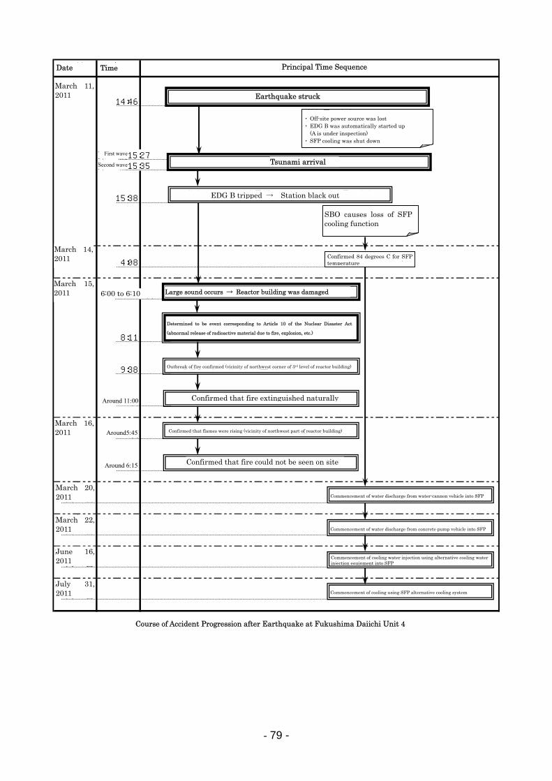
- 79 -
2011年3月11日 14:46
第一波15:27第二波15:35
15:38
2011年3月14日 4:08
2011年3月15日 6:00~6:10頃
8:11
9:38
11:00頃
2011年3月16日 5:45頃
6:15頃
2011年3月20日
2011年3月22日
2011年6月16日
2011年7月31日
福島第一発電所4号機 地震後の事故進展の流れ
日付 時間 主な時系列
地震発生
津 波 襲 来
非常用ディーゼル発電機Bトリップ → 全交流電源喪失
火災発生確認(原子炉建屋3階北西コーナー付近)
自然に火が消えていることを確認
・外部電源喪失・非常用ディーゼル発電機B自動起動 (Aは点検中)・SFP冷却停止
SFP温度84℃確認
大きな音が発生→原子炉建屋損傷
原災法第15条該当事象(火災爆発等による放射性物質異常放出)と判断
SFPへ放水車による放水開始
SFPへコンクリートポンプ車による放水開始
SFPへ仮設注水設備による注水開始
SFP代替冷却系による冷却開始
・SBOによりSFP冷却機能 喪失
炎が上がっていることを確認(原子炉建屋北西部付近)
現場で火が見えないことを確認
Principal Time SequenceTime Date
March 11, 2011
March 14, 2011
March 15, 2011
March 16, 2011
March 20, 2011
March 22, 2011
June 16, 2011
July 31, 2011
Course of Accident Progression after Earthquake at Fukushima Daiichi Unit 4
Around 11:00
Around5:45
Around 6:15
Earthquake struck
Tsunami arrival
Large sound occurs → Reactor building was damaged
Determined to be event corresponding to Article 10 of the Nuclear Disaster Act
(abnormal release of radioactive material due to fire, explosion, etc.)
SBO causes loss of SFP cooling function
EDG B tripped → Station black out
Outbreak of fire confirmed (vicinity of northwest corner of 3rd level of reactor building)
Confirmed that fire extinguished naturally
Confirmed that flames were rising (vicinity of northwest part of reactor building)
Confirmed that fire could not be seen on site
Commencement of water discharge from water-cannon vehicle into SFP
Commencement of water discharge from concrete pump vehicle into SFP
Commencement of cooling water injection using alternative cooling waterinjection equipment into SFP
Commencement of cooling using SFP alternative cooling system
・ Off-site power source was lost ・ EDG B was automatically started up
(A is under inspection) ・ SFP cooling was shut down
Confirmed 84 degrees C for SFP temperature
6:00 to 6:10
Second wave
First wave
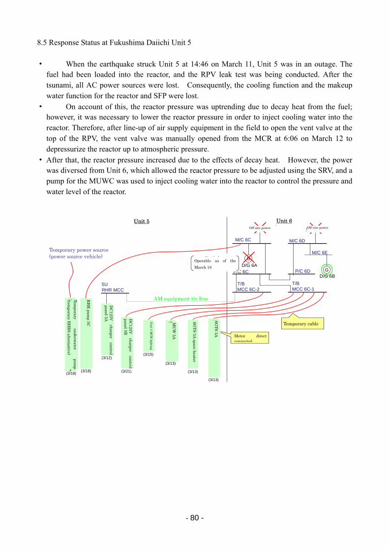
- 80 -
8.5 Response Status at Fukushima Daiichi Unit 5
・ When the earthquake struck Unit 5 at 14:46 on March 11, Unit 5 was in an outage. The fuel had been loaded into the reactor, and the RPV leak test was being conducted. After the tsunami, all AC power sources were lost. Consequently, the cooling function and the makeup water function for the reactor and SFP were lost.
・ On account of this, the reactor pressure was uptrending due to decay heat from the fuel; however, it was necessary to lower the reactor pressure in order to inject cooling water into the reactor. Therefore, after line-up of air supply equipment in the field to open the vent valve at the top of the RPV, the vent valve was manually opened from the MCR at 6:06 on March 12 to depressurize the reactor up to atmospheric pressure.
・ After that, the reactor pressure increased due to the effects of decay heat. However, the power was diversed from Unit 6, which allowed the reactor pressure to be adjusted using the SRV, and a pump for the MUWC was used to inject cooling water into the reactor to control the pressure and water level of the reactor.
5号機5号機 6号機6号機
M/CM/C 6D6D
M/CM/C 6E6E
D/G 6B
M/CM/C 66CC
G
G
D/G 6A
外部電源 外部電源
仮設水中ポンプ(仮設RHRS代替)
残留熱除去系(RHR)ポンプ
5C
P/CP/C 6D6DP/CP/C 6C6C
T/BT/BMCC MCC 6C6C--22
5号機
中操照明
補給水系(MUW)5A
非常用ガス処理系(SGTS)5A
T/BT/BMCC MCC 6C6C--11
DC125V充電器制御盤5B
5U5URHRRHR MCCMCC
AMAM設備タイライン設備タイライン
DC125V充電器制御盤5A
SGTS
5Aスペースヒータ
仮設電源仮設電源(電源車)(電源車)
(3/21)
(3/12)(3/15)
(3/13)
(3/13)
(3/13)
(3/18)(3/18)
18日時点では運転可能
モータ直結
仮設ケーブル
Unit 5 Unit 6
Operable as of the
March 18
Temporary power source (power source vehicle)
Temporary
un
derwater
pum
p
(temporary R
HR
S altern
ative)
RH
R pu
mp 5C
DC
125V
charger
control
panel 5A
DC
125V
charger
control
panel 5B
Un
it 5 MC
R ligh
ting
MU
W 5A
SG
TS
5A space h
eater
SG
TS
5A Motor direct
connected
Temporary cable
Off-site power Off-site power
AM equipment tie line
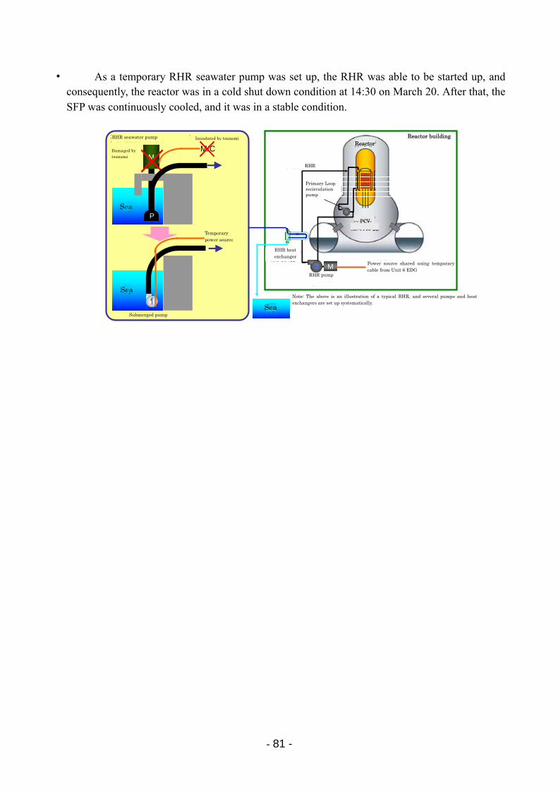
- 81 -
・ As a temporary RHR seawater pump was set up, the RHR was able to be started up, and consequently, the reactor was in a cold shut down condition at 14:30 on March 20. After that, the SFP was continuously cooled, and it was in a stable condition.
原子炉格納容器
残留熱除去系
原子炉再循環ポンプ
原子炉建屋
残留熱除去系ポンプ
残留熱除去系熱交換器
原子炉
(注)上記は残留熱の除去系統を模式的に記載したものであり、ポンプや熱交換器は複数系統設置されている
M 6号機非常用D/Gから仮設ケーブルで電源を共有
海
M
海
津波により破損
P
海
水中ポンプ
仮設電源
M/C残留熱除去海水ポンプ 津波により浸水Inundated by tsunami
Damaged by tsunami
Temporary power source
Submerged pump
Note: The above is an illustration of a typical RHR, and several pumps and heat exchangers are set up systematically.
Reactor building
Sea
Sea
Sea
PCV
Reactor
Primary Loop recirculation pump
RHR
RHR heat exchanger
RHR pump
Power source shared using temporary cable from Unit 6 EDG
RHR seawater pump
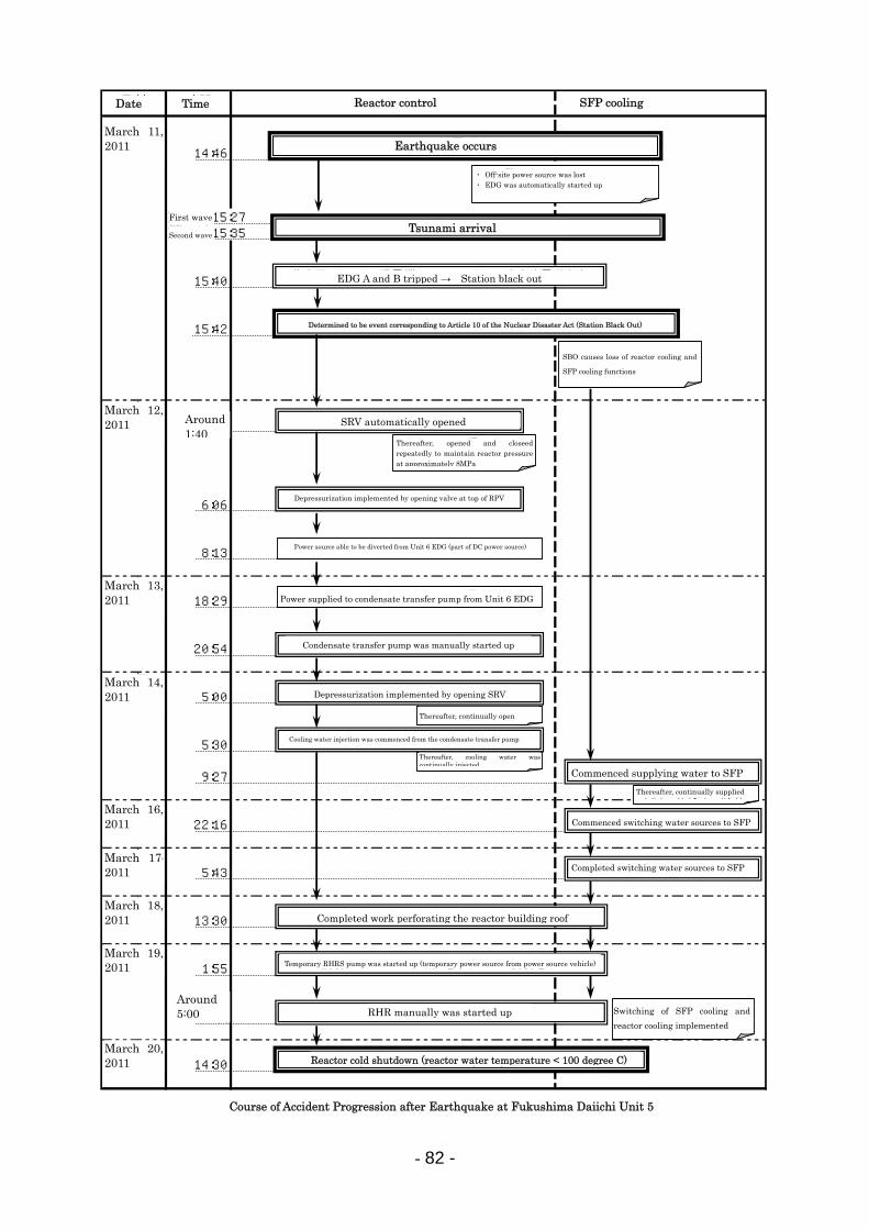
- 82 -
2011年3月11日 14:46
第一波15:27第二波15:35
15:40
15:42
2011年3月12日 1:40頃
6:06
8:13
2011年3月13日 18:29
20:54
2011年3月14日 5:00
5:30
9:27
2011年3月16日 22:16
2011年3月17日 5:43
2011年3月18日 13:30
2011年3月19日 1:55
5:00頃
2011年3月20日 14:30
福島第一発電所5号機 地震後の事故進展の流れ
日付 時間 原子炉制御 使用済燃料プール冷却
地震発生
津 波 襲 来
原災法第10条該当事象(全交流電源喪失:SBO)と判断
・SBOにより原子炉冷却、 SFP冷却機能喪失
・外部電源喪失・非常用ディーゼル発電機自動起動
非常用ディーゼル発電機A,Bトリップ → 全交流電源喪失
逃がし安全弁自動開
・以降、開閉を繰り返し原子炉圧力を約8MPaに維持
原子炉圧力容器頂部の弁開により減圧実施
6号機D/Gより電源融通可能(直流電源の一部)
6号機D/Gより復水移送ポンプへ電源供給
復水移送ポンプ手動起動
逃がし安全弁開操作による減圧実施
復水移送ポンプにより原子炉注水開始
SFPへの水補給開始
SFPへの水入れ替え開始
SFPへの水入れ替え終了
原子炉建屋屋上孔あけ作業終了
仮設RHRSポンプ起動(電源車からの仮設電源)
RHR手動起動
原子炉冷温停止 (原子炉水温<100℃)
・SFP冷却及び原子炉冷却を切り替えて実施
・以降、断続的に補給
・以降、断続的に開操作
・以降、断続的に注水
Date Time Reactor control SFP cooling
Earthquake occurs
Tsunami arrival
Determined to be event corresponding to Article 10 of the Nuclear Disaster Act (Station Black Out)
Reactor cold shutdown (reactor water temperature < 100 degree C)
Course of Accident Progression after Earthquake at Fukushima Daiichi Unit 5
March 11, 2011
March 12, 2011
March 13, 2011
March 14, 2011
March 16, 2011
March 17,
2011
March 18, 2011
March 19, 2011
March 20, 2011
First wave
Second wave
Around 1:40
Around 5:00 RHR manually was started up
Completed work perforating the reactor building roof
Completed switching water sources to SFP
Commenced switching water sources to SFP
Commenced supplying water to SFP
・ Off-site power source was lost ・ EDG was automatically started up
SBO causes loss of reactor cooling and
SFP cooling functions
EDG A and B tripped → Station black out
SRV automatically opened
Depressurization implemented by opening valve at top of RPV
Power source able to be diverted from Unit 6 EDG (part of DC power source)
Power supplied to condensate transfer pump from Unit 6 EDG
Condensate transfer pump was manually started up
Depressurization implemented by opening SRV
Thereafter, continually open
Thereafter, cooling water was continually injected
Thereafter, opened and closeedrepeatedly to maintain reactor pressure at approximately 8MPa
Cooling water injection was commenced from the condensate transfer pump
Temporary RHRS pump was started up (temporary power source from power source vehicle)
Switching of SFP cooling and
reactor cooling implemented
Thereafter, continually supplied
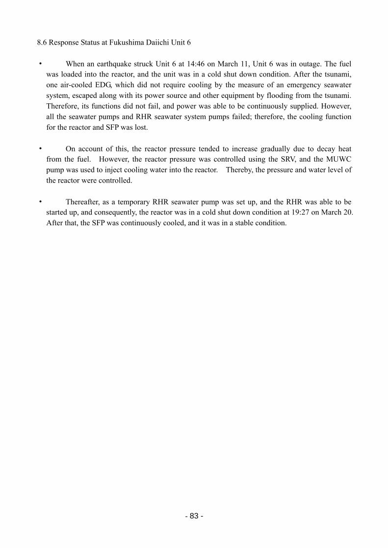
- 83 -
8.6 Response Status at Fukushima Daiichi Unit 6
・ When an earthquake struck Unit 6 at 14:46 on March 11, Unit 6 was in outage. The fuel was loaded into the reactor, and the unit was in a cold shut down condition. After the tsunami, one air-cooled EDG, which did not require cooling by the measure of an emergency seawater system, escaped along with its power source and other equipment by flooding from the tsunami. Therefore, its functions did not fail, and power was able to be continuously supplied. However, all the seawater pumps and RHR seawater system pumps failed; therefore, the cooling function for the reactor and SFP was lost.
・ On account of this, the reactor pressure tended to increase gradually due to decay heat from the fuel. However, the reactor pressure was controlled using the SRV, and the MUWC pump was used to inject cooling water into the reactor. Thereby, the pressure and water level of the reactor were controlled.
・ Thereafter, as a temporary RHR seawater pump was set up, and the RHR was able to be started up, and consequently, the reactor was in a cold shut down condition at 19:27 on March 20. After that, the SFP was continuously cooled, and it was in a stable condition.
- 84 -
2011年3月11日 14:46
第一波15:27第二波15:35
15:36
2011年3月13日 13:01
13:20
2011年3月14日 14:13
2011年3月16日 13:10
2011年3月18日 17:00
19:07
2011年3月19日 4:22
21:26
22:14
2011年3月20日 19:27
福島第一発電所6号機 地震後の事故進展の流れ
日付 時間 原子炉制御 使用済燃料プール冷却
地震発生
津 波 襲 来
・外部電源喪失・非常用ディーゼル発電機自動起動 (D/G6A,D/G6B,HPCS D/G)
非常用ディーゼル発電機2台(D/G6A,HPCS D/G)トリップ
原子炉注水開始
・以降、断続的に注水
SFPへの水の補給開始
非常用ディーゼル発電機D/G6A起動
・D/G6Bは停止せず
復水移送ポンプ手動起動
・以降、断続的に注水
FPCポンプ手動起動
・除熱機能がない 循環運転
原子炉建屋屋上孔あけ作業終了
非常用ディーゼル発電機D/G6A海水ポンプ起動
仮設RHRSポンプ起動(電源車からの仮設電源)
RHR手動起動
・外部電源喪失・非常用ディーゼル発電機自動起動 (D/G6A,D/G6B,HPCS D/G)
・SFP冷却及び原子炉冷却を切り替えて実施
原子炉冷温停止 (原子炉水温<100℃)
・3/14以降SRVにて減圧を断続的に実施
Condensate transfer pump was manually started up
March 11, 2011
March 13, 2011
March 14, 2011
March 16, 2011
March 18, 2011
March 19, 2011
March 20, 2011
Date Time Reactor control SFP cooling
Earthquake struck
Tsunami arrival
Reactor cold shutdown (reactor water temperature < 100 degree C)
Course of Accident Progression after Earthquake at Fukushima Daiichi Unit 6
Two EDG tripped (EDG6A, EDG 6H)
EDG 6B was not shut down
Completed work perforating the reactor building roof
EDG 6A seawater pump was started up
EDG 6A was started up
Temporary RHRS pump started up (temporary power source from power source vehicle)
RHR was manually started up
・ Thereafter, cooling water wascontinually injected
FPC pump manually started up
・ Circulating operation without
heat removal function
・ Thereafter, continuously injected
・ Depressurization was continually implemented by SRV since 3/14
Commenced supplying water to SFP
First wave
Second wave
・ Switching of SFP cooling and reactor cooling implemented
・Off-site power was source lost ・EDG was automatically started up
(EDG6A, EDG6B, EDG6H)
Cooing water injection was commenced into the reactor
- 85 -
8.7 Response Status at Fukushima Daini Unit 1 (1) Course of Principal Accident Responses
・ An earthquake, which had its source off the coast of Sanriku, struck at 14:46 on March 11 while Unit 1 was in rated thermal power output, and the reactor automatically shut down at 14:48.
・ Immediately after the reactor automatically shut down, all control rods were fully inserted, and the reactor was in subcritical condition. The equipments required for cooling the SFP and the cold shut down of the reactor were sound and stable.
・ However, as a result of the tsunami after the earthquake (the first wave arrival was observed at 15:22), equipments required for cooling the SFP and the cold shut down of the reactor were flooded with water and sustained other such damage, rendering it unusable. Because of this, the heat removal from the reactor could no longer be implemented; therefore, at 18:33 on March 11, the site superintendent determined the situation to be an event corresponding to Article 10 of the Nuclear Disaster Act (loss of reactor heat removal function).
・ In addition, due to the loss of reactor heat removal function, the S/C could no longer be cooled, and gradually the water temperature in the S/C increased to over 100 degree C; therefore, the site superintendent determined at 5:22 on March 12 that the situation was an event corresponding to Article 15 of the Nuclear Disaster Act (loss of pressure suppression function).
・ As some of equipments required for cooling the SFP and the cold shut down of the reactor were operable, inspection and maintenance of equipments, which had been flooded in water, were performed and power was supplied using a temporary power source. As a result of the restoration of the reactor heat removal function, the site superintendent determined at 1:24 on March 14 that a recovery had been made from the situation of an event corresponding to Article 10 of the Nuclear Disaster Act (loss of reactor heat removal function).
Subsequently, by cooling the S/C, the water temperature in the S/C dropped below 100 degrees C; therefore, the site superintendent determined at 10:15 that a recovery had been made from the situation of an event corresponding to Article 15 of the Nuclear Disaster Act (loss of pressure suppression function).
・ Thereafter, the RHR continued to remove heat from the reactor, and a cold shut down was achieved with the reactor water temperature under 100 degrees C at 17:00 on March 14, and the SFP was continuously cooled, and the plant is currently being maintained in stable condition.
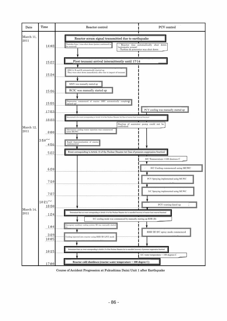
- 86 -
2011年3月11日
14:48
15:22
15:34
15:36
15:55
17:53
18:33
2011年3月12日 0:00
3:50~4:56
5:22
6:20
7:10
7:37
10:21~18:30
2011年3月14日 1:24
1:44
3:3910:05
10:15
17:00
福島第二発電所1号機 地震後の事故進展の流れ
日付 時間 原子炉制御 格納容器制御
復水補給水系による代替注水開始
原子炉急速減圧実施
原子炉隔離時冷却系手動起動
非常用ディーゼル発電機A,B,H自動起動直後に津波の影響により停止
地震による原子炉スクラム信号発信
第 一 波 津 波 襲 来 (17:14まで断続的に襲来)
原災法第15条該当事象の解除(圧力抑制機能の回復)と判断
原災法第10条該当事象(原子炉除熱機能喪失)と判断
・原子炉自動停止(自動スクラム)・タービン・発電機停止
格納容器耐圧ベントライン構成
主蒸気隔離弁手動全閉
富岡線1回線停止(受電は継続)
原子炉減圧開始(主蒸気逃がし安全弁自動開)
格納容器冷却系手動起動
・海水ポンプ起動確認できず
原災法第15条該当事象(圧力抑制機能喪失)と判断
・圧力抑制室温度>100℃
復水補給水系による格納容器スプレイ実施
復水補給水系による圧力抑制室スプレイ実施
復水補給水系による圧力抑制室冷却開始
原災法第10条該当事象の解除(原子炉除熱機能の回復)と判断
非常用補機冷却系(B)手動起動
残留熱除去系(B)圧力抑制室スプレイモード開始残留熱除去系(B)低圧注水モードに
よる原子炉注水実施
原子炉冷温停止 (原子炉水温<100℃)
・圧力抑制室水温<100℃
・残留熱除去系(B)手動起動による圧力抑制室冷却モード開始
March 11, 2011
March 12, 2011
March 14, 2011
Date Time Reactor control PCV control
Reactor scram signal transmitted due to earthquake
First tsunami arrival intermittently until 17:14
Determined to be event corresponding to Article 10 of the Nuclear Disaster Act (loss of reactor heat removal function)
Event corresponding to Article 15 of the Nuclear Disaster Act (loss of pressure suppression function)
Determined that an event corresponding to Article 10 of the Nuclear Disaster Act is cancelled (recovery of reactor heat removal function)
Determined that an event corresponding to Article 15 of the Nuclear Disaster Act is cancelled (recovery of pressure suppression function)
Reactor cold shutdown (reactor water temperature < 100 degree C)
Course of Accident Progression at Fukushima Daini Unit 1 after Earthquake
Tomioka Line 1 was shut down (power continued to be received)
・ Reactor was automatically shut down (automatic scram) ・Turbine & generator was shut down
EDG A, B and H automatically started up They were shut down immediately after due to impact of tsunami
Alternative cooling water injection was commenced using MUWC
Startup of seawater pump could not be confirmed
Rapid depressurization of reactor implemented
S/C Temperature >100 degrees C
Emergency auxiliary cooling system (B) was manually started up
S/C Cooling commenced using MUWC
PCV Spraying implemented using MUWC
S/C Spraying implemented using MUWC
PCV venting lined up
S/C cooling mode was commenced by manually starting up RHR (B)
RHR (B) S/C spray mode commenced
Cooling injected into reactor using RHR (B) LPCI mode
MSIV was manually started up
RCIC was manually started up
Depression commenced of reactor (SRV automatically completely opened up)
PCV cooling was manually started up
S/C water temperature < 100 degrees C
- 87 -
(2) Response Status for Cooling Water Injection at Fukushima Daini Unit 1
・ After the earthquake struck, the MSIVs were completely closed manually at 15:36 on March 11, and the pressure of the reactor was controlled by the measure of the SRV. The RCIC was manually started up at 15:36, and cooling water injected into the reactor. (Thereafter, automatic shutdowns and manual startups were repeated in keeping with “high reactor water level (L-8)” of the RCIC to adjust reactor water level.)
・ Due to flooding of the reactor building annex area as a result of the tsunami, the emergency power sources (M/C 1C and M/C 1H) were unusable, resulting in a situation where the low pressure core spray system pump, RHR pump (A), and high pressure core spray system pump could not be started up.
・ In addition, on account of flooding of the seawater heat exchanger building as well as the operation/shutdown indicator lamps and other factors, the situation was determined to be one in which none of the pumps* of the emergency component cooling system could be started up. (At a later date, it was confirmed in the field that this was due to their being inoperable because some of the motors and emergency power sources (P/C 1C-2, 1D-2) had been covered with water.) Consequently, none of the ECCS pumps could be started up, and function for removing residual heat from the reactor was lost; therefore, the site superintendent determined at 18:33 on March 11 that the situation was an event corresponding to Article 10 of the Nuclear Disaster Act (loss of reactor residual heat removal function).
* Emergency component cooling system pumps include:
RHR cooling system pumps (A, B, C, D); RHR seawater system pumps (A, B, C, D); EDG cooling system pumps (A, B); High pressure core spray system diesel generator cooling system pump; and High pressure core spray system diesel generator cooling seawater system pump.
・ The cooling water injection into the reactor was initially implemented with the RCIC; however, beginning at 0:00 on March 12, it was implemented concurrently with alternative cooling water injection using the MUWC, which was introduced as an AM measure.
・ On March 12 at 3:50, the RPV was in the thermal capacity limit due to the relationship between the reactor pressure and the water temperature of the S/C; therefore, rapid depressurization of the reactor was commenced.
・ The RCIC was manually shut down at 4:58 due to a decrease in the steam pressure for operating the turbine of the RCIC following prompt depressurization, and from this point on, the water level of the reactor was adjusted by measure of alternative cooling water injection using the MUWC.
・ On March 12 at 5:22, the water temperature in the S/C was over 100 degrees C; therefore, the site superintendent determined that it was an event corresponding to Article 15 of the Nuclear Disaster Act (loss of pressure suppression function). The water temperature in question rose to a maximum of approximately 130 degrees C (11:30, March 13).
・ In order to cool the S/C, beginning at 6:20 on March 12, a cooling drainage water line to
- 88 -
the S/C from a cooler on the flammability control system was utilized to inject cooling water (MUWC) into the S/C. The alternative cooling water injection into the reactor by measure of the MUWC was switched to the D/W spray at 7:10 in order to spray into the S/C. At 7:37, alternative cooling water injection for the PCV was started.
・ Concurrent with the cooling into the S/C, inspection and maintenance were performed on the RHR cooling system pump (D), the RHR seawater system pump (B), and the EDG cooling system pump (B) (motors were replaced on the RHR component cooling system pump (D) and the EDG cooling system pump (B)).
・ In addition, because the seawater heat exchanger building and the emergency power sources (P/C1C-2 and 1D-2) were flooded, the temporary cable and high-voltage power generating vehicle, which were urgently arranged for from outside the station, were used, and a temporary cable was laid. Moreover, power received from the power source for the radwaste building, which was receiving power from an off-site power supply system. By receiving power from the high-voltage power generating vehicle, the RHR cooling system pump (D), the RHR seawater system pump (B), and the EDG cooling system pump (B) were restored to a status in which they could be started. They were then successively started up at 20:17 on March 13.
・ On March 14 at 1:24, after the RHR seawater system pump (B) having been started up, the site superintendent determined that a recovery had been made from the situation of an event corresponding to Article 10 of the Nuclear Disaster Act (loss of reactor heat removal function).
・ In addition, as a result of cooling the S/C with the RHR pump (B), the water temperature in the S/C gradually decreased and, at 10:15 on March 14, the water temperature in the S/C was under 100 degrees C. Therefore, the site superintendent determined that a recovery had been made from the situation of an event corresponding to Article 15 of the Nuclear Disaster Act (loss of pressure suppression function).
・ Furthermore, in addition to cooling the S/C in order to cool the reactor water at an early stage, an implementation procedure manual was created based on the operation manual for accidents stipulated beforehand. Beginning at 10:05 on March 14, a stopgap method of cooling was implemented that commenced the cooling water injection into the reactor using water in the S/C through a low pressure injection line by measure of the RHR pump (B). A SRV was opened causing reactor water to flow into the S/C, and water in the S/C was cooled by the measure of the RHR heat exchanger (B). The water was re-injected into the reactor through a low pressure cooling water injection line (S/C → RHR pump (B) → RHR heat exchanger (B) → low pressure injection line → reactor → SRV → S/C). As a result of this operation, at 17:00, it was confirmed that the reactor water temperature was below 100 degree C and the reactor was in cold shutdown.
(3) Response Status Pertaining to Venting of PCV at Fukushima Daini Unit 1
・ On March 11 at 14:48, in keeping with “low reactor water level (L-3),” which occurred when the reactor automatically shut down, the primary containment vessel isolation system and the SGTS operated normally, and isolation of the PCV and negative pressure in the reactor building were maintained.
・ Thereafter, the pressure in the PCV uptrended, and it was estimated that it would take time to restore the reactor heat removal function. On March 12 beginning at 10:21 until 18:30, PCV venting was lined up (one action remained to open the outlet valve on the side of the S/C).

- 89 -
・ The PCV pressure increased up to a maximum of approximately 282 kPa[gage] (on the S/C side), but did not reach the PCV maximum operating pressure of 310 kPa[gage].
- 90 -
8.8 Radiation Dose Rate Fluctuations along the Site Boundary of the Fukushima Daiichi Nuclear Power during the Accident
After the disaster, monitoring posts, which were set up in the area surrounding the power
station, were shut down, and the radiation dose rate was not able to be measured. Therefore, the radiation dose rate was measured by using monitoring cars.
The results measured by a monitoring car near the main gate during the events were considered to be associated with radioactive material released into the environment during venting of PCVs and the building explosions. These are shown in the figure below (radiational dose rate in vicinity of Fukushima Daiichi NPS main gate).
From March 11 until dawn of March 12, the radiation dose was normal. However, the radiation dose rate began to increase at around 5:00 on March 12. This was caused by the release of radioactive material from Unit 1, where core damage was postulated to have already occurred.
On March 12 at around 10:00, when the line-up was in place for venting the PCV of Unit 1, the radiation dose rate appeared to peak. However, a pressure drop in the PCV was not confirmed, and the cause of the peak has not been cleared. Subsequently, the PCV venting (on the side of the S/C) of Unit 1 was conducted, and there was an explosion in the building. However, no unusual peak in the radiation dose rate was seen. On March 13, PCV venting was performed several times at Unit 3 (on the side of the S/C), and a peak was confirmed. However, the radiation dose rate was less than 10μSv/h, and an increase in the background was not confirmed.
On the night of March 14, it is postulated that core damage occurred at Unit 2, and
thereafter, there was a rise in the background. In particular, at 11:25 on March 15, when the Unit 2 D/W pressure dropped from 730 kPa[abs] to 155 kPa[abs]. At this time, a significant increase was confirmed in the background level with the radiation dose rate exceeding 1,000 μSv/h and reaching a maximum of 10,000 μSv/h.
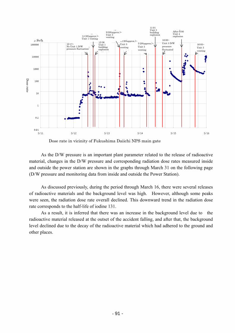
- 91 -
As the D/W pressure is an important plant parameter related to the release of radioactive material, changes in the D/W pressure and corresponding radiation dose rates measured inside and outside the power station are shown in the graphs through March 31 on the following page (D/W pressure and monitoring data from inside and outside the Power Station).
As discussed previously, during the period through March 16, there were several releases
of radioactive materials and the background level was high. However, although some peaks were seen, the radiation dose rate overall declined. This downward trend in the radiation dose rate corresponds to the half-life of iodine 131.
As a result, it is inferred that there was an increase in the background level due to the radioactive material released at the outset of the accident falling, and after that, the background level declined due to the decay of the radioactive material which had adhered to the ground and other places.
0.01
0.1
1
10
100
1000
10000
100000
3/11 3/12 3/13 3/14 3/15 3/16
10:17~1号機 D/W圧力変動なし
14:30 頃~1号機ベント
15:361号機建屋爆発
9:20 頃~3号機ベント
12:30~3号機ベント
11:013号機建屋爆発
6時過ぎ4号機爆発
16:05~3号機ベント
5:20~3号機ベント
16:00~ 3号機 D/W 圧力変動あり
10:17~ No Unit 1 D/W pressure fluctuation
15:36Unit 1 building explosion
16:00~ Unit 3 D/W pressure fluctuated
11:01Unit 3 building explosion
12:20(approx.)~Unit 3 venting
Dose rate in vicinity of Fukushima Daiichi NPS main gate
Dose rate
μSv/h 14:30(approx.)~Unit 1 venting
9:20(approx.)~Unit 3 venting
After 6:00 Unit 4 explosion
16:05~ Unit 3 venting
5:20(approx.)~Unit 3 venting
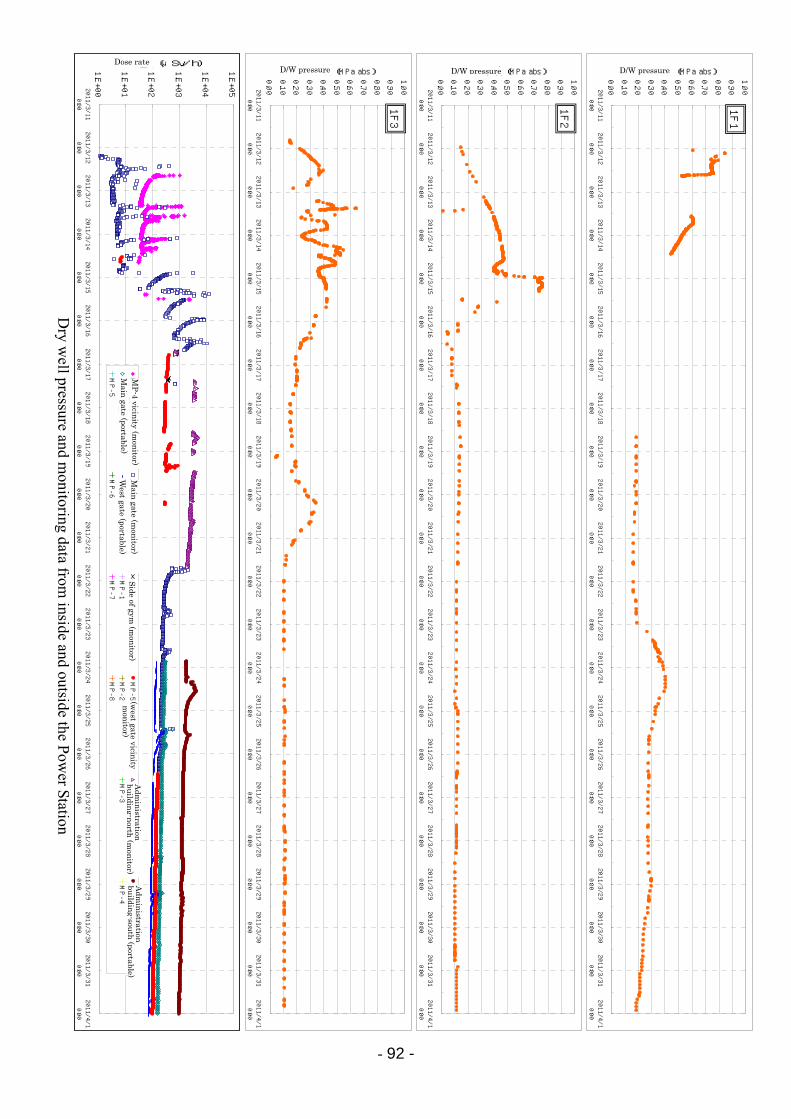
- 92 -
0.00
0.10
0.20
0.30
0.40
0.50
0.60
0.70
0.80
0.90
1.002011/3/11
0:00
2011/3/12
0:00
2011/3/13
0:00
2011/3/14
0:00
2011/3/15
0:00
2011/3/16
0:00
2011/3/17
0:00
2011/3/18
0:00
2011/3/19
0:00
2011/3/20
0:00
2011/3/21
0:00
2011/3/22
0:00
2011/3/23
0:00
2011/3/24
0:00
2011/3/25
0:00
2011/3/26
0:00
2011/3/27
0:00
2011/3/28
0:00
2011/3/29
0:00
2011/3/30
0:00
2011/3/31
0:00
2011/4/1
0:00
D/W圧力(MPa abs)
1F1
0.00
0.10
0.20
0.30
0.40
0.50
0.60
0.70
0.80
0.90
1.002011/3/11
0:00
2011/3/12
0:00
2011/3/13
0:00
2011/3/14
0:00
2011/3/15
0:00
2011/3/16
0:00
2011/3/17
0:00
2011/3/18
0:00
2011/3/19
0:00
2011/3/20
0:00
2011/3/21
0:00
2011/3/22
0:00
2011/3/23
0:00
2011/3/24
0:00
2011/3/25
0:00
2011/3/26
0:00
2011/3/27
0:00
2011/3/28
0:00
2011/3/29
0:00
2011/3/30
0:00
2011/3/31
0:00
2011/4/1
0:00
D/W圧力(MPa abs)
1F2
0.00
0.10
0.20
0.30
0.40
0.50
0.60
0.70
0.80
0.90
1.002011/3/11
0:00
2011/3/12
0:00
2011/3/13
0:00
2011/3/14
0:00
2011/3/15
0:00
2011/3/16
0:00
2011/3/17
0:00
2011/3/18
0:00
2011/3/19
0:00
2011/3/20
0:00
2011/3/21
0:00
2011/3/22
0:00
2011/3/23
0:00
2011/3/24
0:00
2011/3/25
0:00
2011/3/26
0:00
2011/3/27
0:00
2011/3/28
0:00
2011/3/29
0:00
2011/3/30
0:00
2011/3/31
0:00
2011/4/1
0:00
D/W圧力(MPa abs)
1F3
1.E+00
1.E+01
1.E+02
1.E+03
1.E+04
1.E+052011/3/11
0:00
2011/3/12
0:00
2011/3/13
0:00
2011/3/14
0:00
2011/3/15
0:00
2011/3/16
0:00
2011/3/17
0:00
2011/3/18
0:00
2011/3/19
0:00
2011/3/20
0:00
2011/3/21
0:00
2011/3/22
0:00
2011/3/23
0:00
2011/3/24
0:00
2011/3/25
0:00
2011/3/26
0:00
2011/3/27
0:00
2011/3/28
0:00
2011/3/29
0:00
2011/3/30
0:00
2011/3/31
0:00
2011/4/1
0:00
線量率(μSv/h)
MP-4付近(モニカー)
正門付近(モニカー)
体育館脇(モニカー)
MP-5(西門付近モニカー)
事務本館北(モニカー)
事務本館南(可搬型)
正門(可搬型)
西門(可搬型)
MP-1
MP-2
MP-3
MP-4
MP-5
MP-6
MP-7
MP-8
Dry w
ell pressure and monitoring data from
inside andoutside the P
ower Station
Dose rate D/W pressure D/W pressure D/W pressure
MP
-4 vicinity (mon
itor)M
ain gate (portable)
West gate (portable)
Main
gate (mon
itor)S
ide of gym (m
onitor)
(west gate vicin
ity m
onitor)
Adm
inistration
bu
ilding-north
(mon
itor)A
dmin
istration
building-sou
th (portable)
- 93 -
8.9 Storage Status for Spent Fuel (1) Storage Status for Spent Fuel at Fukushima Daiichi NPS [Attachment 8-8]
The number of spent fuel rods in the storage as of March 11
Unit No. of spent fuel rods
No. of new fuel rods
Unit 1 292 100
Unit 2 587 28
Unit 3 514 52
Unit 4 1331 204
Unit 5 946 48
Unit 6 876 64
Common pool 6375 0
Cask storage building 408 0
Units 1 to 5 and the common pool lost all AC power due to the tsunami. Therefore, the
SFP cooling function and the makeup water function were lost. In addition, although the EDG 6B at Unit 6 retained its function, the function of the seawater pump was lost. Accordingly, the SFP cooling function was lost.
Futhermore, all AC power for the cask storage building was also lost; however, the dry storage casks were designed to be air cooled by natural convection.
The following descriptions are the cooling conditions of the dry storage casks, common pool and spent fuel storage pools at Units 1 to 6.
Unit 1: As the upper structure of the reactor building was damaged due to the explosion on
March 12, cooling water was supplied to the Unit 1 SFP applying a concrete pump vehicle to spray water starting on March 31. From May 28, cooling water was injected using pipes from the fuel pool cooling cleanup system. An alternative cooling system has been applied for SFP cooling since August 10.
Unit 2: On March 20, cooling water was injected using pipes from the fuel pool cooling cleanup system. An alternative cooling system was started on May 31.
Unit 3: As the upper structure of the reactor building was damaged due to the explosion on March 14, water was sprayed by a helicopter on March 17, and from March 17, a water-cannon vehicle and a refractive water cannon tower vehicle were used to spray water. Furthermore, a concrete pump vehicle was used for spraying water starting on March 27. Cooling water started to be injected using pipes from the fuel pool cooling cleanup system on April 22. An alternative cooling system has been used for SFP cooling since August 30.
- 94 -
Unit 4: As the upper structure of the reactor building was damaged due to the explosion on March 15, cooling water was supplied to Unit 4 SFP using a water cannon vehicle to spray water starting on March 20. A concrete pump vehicle was used for spraying water starting on March 22. The injection of cooling water was started on June 16 using temporary fuel pool cooling injection equipment, and an alternative cooling system has been used for SFP cooling since July 31.
Unit 5: On March 19, the RHR pump was manually started in the emergency heat load mode. The fuel pool cooling cleanup system has been operated since June 25.
Unit 6: On March 19, the RHR pump was manually started in the emergency heat load mode.
Common pool:
Following restoration of an off-site power source, temporary power equipment was supplied to the common pool and cooling has been operated with temporary power since March 24.
Cask storage
building:
Due to the impact of the tsunami, a large amount of seawater, sand, debris and other such material flowed into the cask storage building through louvers and doors However, the natural air cooling was not obstructed, and it was confirmed that there were no problems in cooling. No abnormalities were identified by the visual inspection.
As described above, the Units 1 to 6 water-cooled SFPs and the common pool were stable
at a water temperature between 30 and 50 degrees C, and no abnormalities were observed with the cooling of the air-cooled dry storage casks.
In addition, an assessment regarding the water level of the Units 1 to 6 SFPs and common pool after the earthquake presumed that the water level was adequate to cover the spent fuel in all pools, and that the fuel was not exposed.
At Unit 4, all of the fuel in the reactor had been moved to the SFP as part of the outage, when the upper structure of the reactor building was damaged as a result of the explosion. As there was no possibility of hydrogen being generated from the reactor, it was postulated that hydrogen came from fuel damage due to lack of water caused by leakage in the SFP. However, it was confirmed by helicopter on March 16 that the water level in the pool was adequate enough and that the fuel was not exposed. In addition, the results of a nuclide analysis of the pool water confirmed that there was no damage in the fuel.
Presently, the pool is being cooled and the water level is being maintained; therefore, it is believed that there is no structural damage to the pool.
(2) Storage Status for Spent Fuel at Fukushima Daini NPS
The cooling function for all four the SFPs at Fukushima Daini was temporarily lost. However, SFP water level and water temperatures of less than 65 degrees C were able to be maintained as specified by the reactor facility safety provisions.
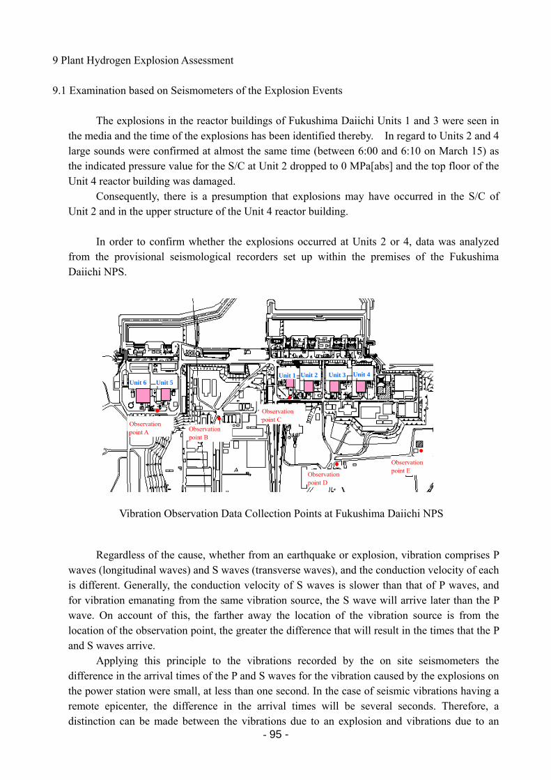
- 95 -
9 Plant Hydrogen Explosion Assessment 9.1 Examination based on Seismometers of the Explosion Events
The explosions in the reactor buildings of Fukushima Daiichi Units 1 and 3 were seen in the media and the time of the explosions has been identified thereby. In regard to Units 2 and 4 large sounds were confirmed at almost the same time (between 6:00 and 6:10 on March 15) as the indicated pressure value for the S/C at Unit 2 dropped to 0 MPa[abs] and the top floor of the Unit 4 reactor building was damaged.
Consequently, there is a presumption that explosions may have occurred in the S/C of Unit 2 and in the upper structure of the Unit 4 reactor building.
In order to confirm whether the explosions occurred at Units 2 or 4, data was analyzed
from the provisional seismological recorders set up within the premises of the Fukushima Daiichi NPS.
Vibration Observation Data Collection Points at Fukushima Daiichi NPS
Regardless of the cause, whether from an earthquake or explosion, vibration comprises P waves (longitudinal waves) and S waves (transverse waves), and the conduction velocity of each is different. Generally, the conduction velocity of S waves is slower than that of P waves, and for vibration emanating from the same vibration source, the S wave will arrive later than the P wave. On account of this, the farther away the location of the vibration source is from the location of the observation point, the greater the difference that will result in the times that the P and S waves arrive.
Applying this principle to the vibrations recorded by the on site seismometers the difference in the arrival times of the P and S waves for the vibration caused by the explosions on the power station were small, at less than one second. In the case of seismic vibrations having a remote epicenter, the difference in the arrival times will be several seconds. Therefore, a distinction can be made between the vibrations due to an explosion and vibrations due to an
観測点B 観測点A
観測点C
観測点D
観測点E
1号 2号 3号 4号
6号 5号
観測点B 観測点A
観測点C
観測点D
観測点E
観測点B 観測点A
観測点C
観測点D
観測点E
1号 2号 3号 4号
6号 5号
1号 2号 3号 4号
6号 5号
Observation point A
Unit 6 Unit 5 Unit 1 Unit 2 Unit 3 Unit 4
Observation point B
Observation point C
Observation point D
Observation point E
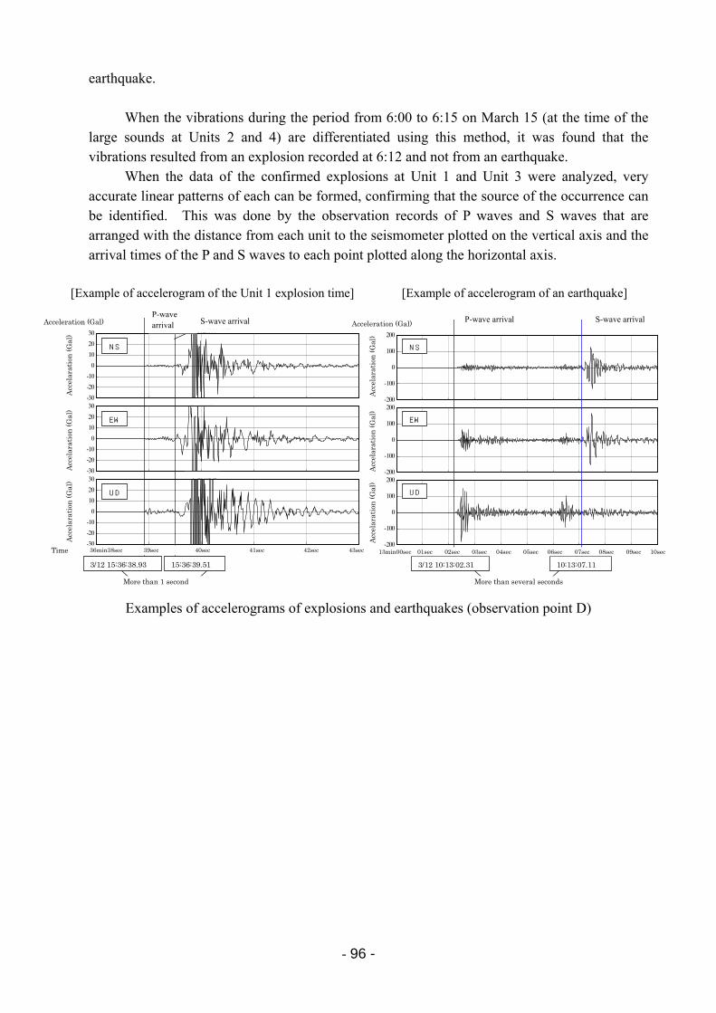
- 96 -
earthquake.
When the vibrations during the period from 6:00 to 6:15 on March 15 (at the time of the large sounds at Units 2 and 4) are differentiated using this method, it was found that the vibrations resulted from an explosion recorded at 6:12 and not from an earthquake.
When the data of the confirmed explosions at Unit 1 and Unit 3 were analyzed, very accurate linear patterns of each can be formed, confirming that the source of the occurrence can be identified. This was done by the observation records of P waves and S waves that are arranged with the distance from each unit to the seismometer plotted on the vertical axis and the arrival times of the P and S waves to each point plotted along the horizontal axis.
Examples of accelerograms of explosions and earthquakes (observation point D)
13分00秒 01秒 02秒 03秒 04秒 05秒 06秒 07秒 08秒 09秒 10秒
-200
-100
0
100
200
-200
-100
0
100
200-200
-100
0
100
200
3/12 10:13:02.31 10:13:07.11
NS
EW
UD
加速度
(Gal
)加速度
(Gal
)加速度
(Gal
)
P波到達 S波到達
数秒以上
[Example of accelerogram of the Unit 1 explosion time] [Example of accelerogram of an earthquake]
3/12 15:36:38.93 15:36:39.51
36分38秒 39秒 40秒 41秒 42秒 43秒
-30
-20
-10
0
10
20
30 102.044
-30
-20
-10
0
10
20
30 90.550
-30
-20
-10
0
10
20
30 231.242
NS
EW
UD
加速度
(Gal
)加速度
(Gal
)加速度
(Gal
)
P波到達 S波到達
1秒以内
P-wave arrival P-wave arrival S-wave arrivalS-wave arrival
More than several seconds More than 1 second
Time
Acceleration (Gal) Acceleration (Gal)
Acc
elar
atio
n (
Gal
)
Acc
elar
atio
n (
Gal
)
Acc
elar
atio
n (
Gal
)
Acc
elar
atio
n (
Gal
)
Acc
elar
atio
n (
Gal
)
Acc
elar
atio
n (
Gal
)
36min38sec 39sec 40sec 41sec 42sec 43sec 13min00sec 01sec 02sec 03sec 04sec 05sec 06sec 07sec 08sec 09sec 10sec
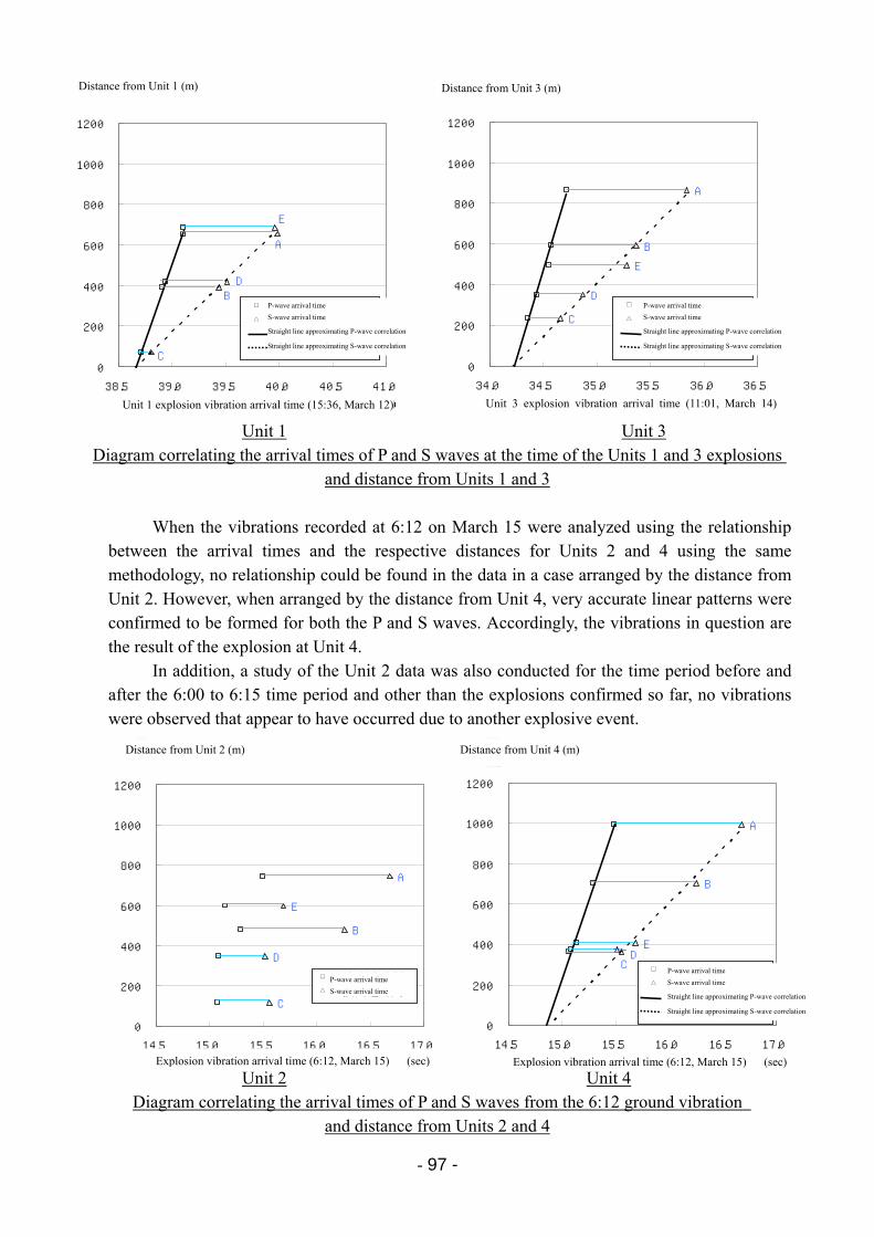
- 97 -
Unit 1 Unit 3 Diagram correlating the arrival times of P and S waves at the time of the Units 1 and 3 explosions
and distance from Units 1 and 3
When the vibrations recorded at 6:12 on March 15 were analyzed using the relationship between the arrival times and the respective distances for Units 2 and 4 using the same methodology, no relationship could be found in the data in a case arranged by the distance from Unit 2. However, when arranged by the distance from Unit 4, very accurate linear patterns were confirmed to be formed for both the P and S waves. Accordingly, the vibrations in question are the result of the explosion at Unit 4.
In addition, a study of the Unit 2 data was also conducted for the time period before and after the 6:00 to 6:15 time period and other than the explosions confirmed so far, no vibrations were observed that appear to have occurred due to another explosive event.
Unit 2 Unit 4 Diagram correlating the arrival times of P and S waves from the 6:12 ground vibration
and distance from Units 2 and 4
3号機爆発振動到達時刻(3月14日11時01分)
C
D
E
B
A
0
200
400
600
800
1000
1200
34.0 34.5 35.0 35.5 36.0 36.5
(秒)
3号機からの距離(m)
P波到達時刻
S波到達時刻
□ P波到達時刻 △ S波到達時刻
P波相関近似直線 S波相関近似直線
1号機爆発振動到達時刻(3月12日15時36分)
E
A
DB
C0
200
400
600
800
1000
1200
38.5 39.0 39.5 40.0 40.5 41.0
(秒)
1号機からの距離(m)
P波到達時刻
S波到達時刻
□ P波到達時刻 △ S波到達時刻
P波相関近似直線 S波相関近似直線
Distance from Unit 3 (m)Distance from Unit 1 (m)
Unit 1 explosion vibration arrival time (15:36, March 12) Unit 3 explosion vibration arrival time (11:01, March 14)
P-wave arrival time
S-wave arrival time
Straight line approximating P-wave correlation
Straight line approximating S-wave correlation
P-wave arrival time
S-wave arrival time
Straight line approximating P-wave correlation
Straight line approximating S-wave correlation
爆発振動到達時刻(3月15日06時12分)
CDE
B
A
0
200
400
600
800
1000
1200
14.5 15.0 15.5 16.0 16.5 17.0(秒)
4号機からの距離(m)
P波到達時刻
S波到達時刻
□ P波到達時刻△ S波到達時刻
P波相関近似直線S波相関近似直線
爆発振動到達時刻(3月15日06時12分)
A
B
E
D
C
0
200
400
600
800
1000
1200
14.5 15.0 15.5 16.0 16.5 17.0(秒)
2号機からの距離(m)
P波到達時刻
S波到達時刻
□ P波到達時刻△ S波到達時刻
Distance from Unit 2 (m) Distance from Unit 4 (m)
Explosion vibration arrival time (6:12, March 15) (sec) Explosion vibration arrival time (6:12, March 15) (sec)
P-wave arrival time
S-wave arrival time
P-wave arrival time
S-wave arrival time
Straight line approximating P-wave correlation
Straight line approximating S-wave correlation
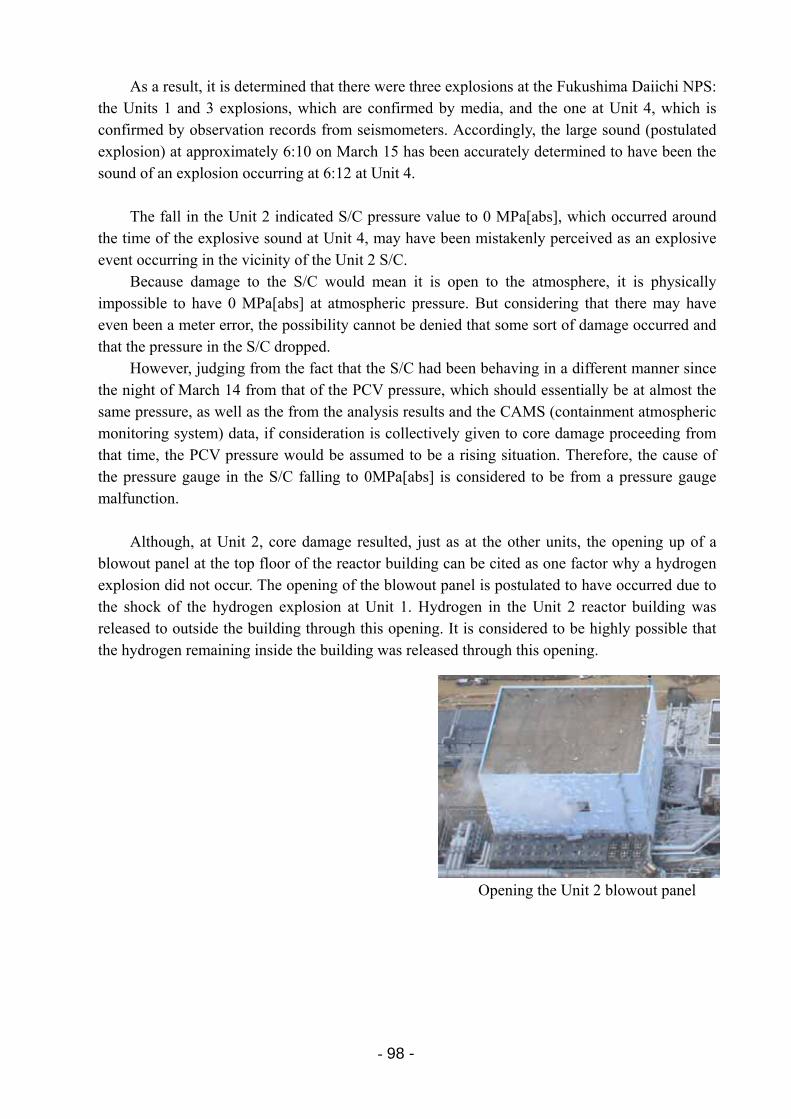
- 98 -
As a result, it is determined that there were three explosions at the Fukushima Daiichi NPS: the Units 1 and 3 explosions, which are confirmed by media, and the one at Unit 4, which is confirmed by observation records from seismometers. Accordingly, the large sound (postulated explosion) at approximately 6:10 on March 15 has been accurately determined to have been the sound of an explosion occurring at 6:12 at Unit 4.
The fall in the Unit 2 indicated S/C pressure value to 0 MPa[abs], which occurred around
the time of the explosive sound at Unit 4, may have been mistakenly perceived as an explosive event occurring in the vicinity of the Unit 2 S/C.
Because damage to the S/C would mean it is open to the atmosphere, it is physically impossible to have 0 MPa[abs] at atmospheric pressure. But considering that there may have even been a meter error, the possibility cannot be denied that some sort of damage occurred and that the pressure in the S/C dropped.
However, judging from the fact that the S/C had been behaving in a different manner since the night of March 14 from that of the PCV pressure, which should essentially be at almost the same pressure, as well as the from the analysis results and the CAMS (containment atmospheric monitoring system) data, if consideration is collectively given to core damage proceeding from that time, the PCV pressure would be assumed to be a rising situation. Therefore, the cause of the pressure gauge in the S/C falling to 0MPa[abs] is considered to be from a pressure gauge malfunction.
Although, at Unit 2, core damage resulted, just as at the other units, the opening up of a
blowout panel at the top floor of the reactor building can be cited as one factor why a hydrogen explosion did not occur. The opening of the blowout panel is postulated to have occurred due to the shock of the hydrogen explosion at Unit 1. Hydrogen in the Unit 2 reactor building was released to outside the building through this opening. It is considered to be highly possible that the hydrogen remaining inside the building was released through this opening.
Opening the Unit 2 blowout panel
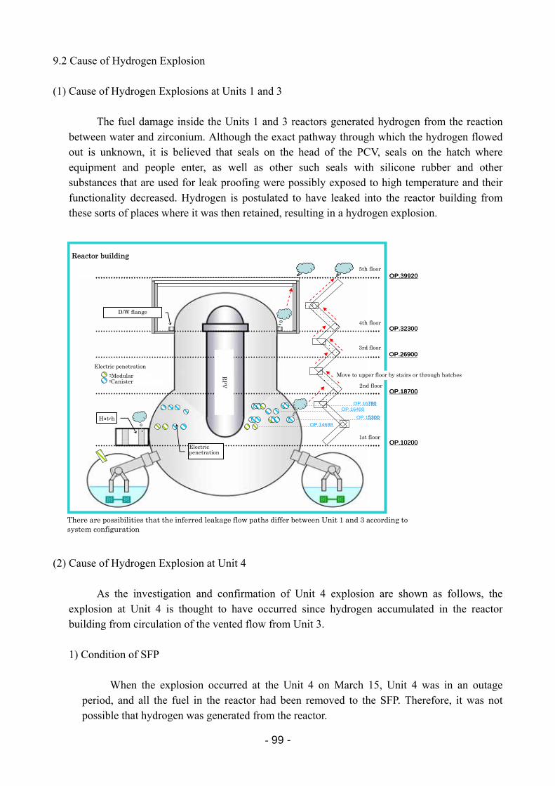
- 99 -
9.2 Cause of Hydrogen Explosion (1) Cause of Hydrogen Explosions at Units 1 and 3
The fuel damage inside the Units 1 and 3 reactors generated hydrogen from the reaction between water and zirconium. Although the exact pathway through which the hydrogen flowed out is unknown, it is believed that seals on the head of the PCV, seals on the hatch where equipment and people enter, as well as other such seals with silicone rubber and other substances that are used for leak proofing were possibly exposed to high temperature and their functionality decreased. Hydrogen is postulated to have leaked into the reactor building from these sorts of places where it was then retained, resulting in a hydrogen explosion.
(2) Cause of Hydrogen Explosion at Unit 4
As the investigation and confirmation of Unit 4 explosion are shown as follows, the explosion at Unit 4 is thought to have occurred since hydrogen accumulated in the reactor building from circulation of the vented flow from Unit 3. 1) Condition of SFP
When the explosion occurred at the Unit 4 on March 15, Unit 4 was in an outage period, and all the fuel in the reactor had been removed to the SFP. Therefore, it was not possible that hydrogen was generated from the reactor.
5階
4階
2階
1階
3階
原子炉建屋
OP.10200
OP.18700
OP.26900
OP.32300
OP.39920
OP.16780OP.16400
OP.15300
OP.14688ハッチ
電気ペネトレーション
ドライウェルフランジ
:モジュール型:キャニスタ型
電気ペネトレーション
5階
4階
2階
1階
3階
原子炉建屋
OP.10200
OP.18700
OP.26900
OP.32300
OP.39920
OP.16780OP.16400
OP.15300
OP.14688ハッチ
電気ペネトレーション
ドライウェルフランジ
:モジュール型:キャニスタ型
電気ペネトレーション
階段・ハッチ等を通じて上層階に移行
推定漏洩経路はシステム構成の違いにより、1号機と3号機で若干異なる可能性あり。 There are possibilities that the inferred leakage flow paths differ between Unit 1 and 3 according to system configuration
Reactor building
D/W flange
Electric penetration
Modular Canister
Hatch
Electric penetration
Move to upper floor by stairs or through hatches
1st floor
2nd floor
3rd floor
4th floor
5th floor
RP
V
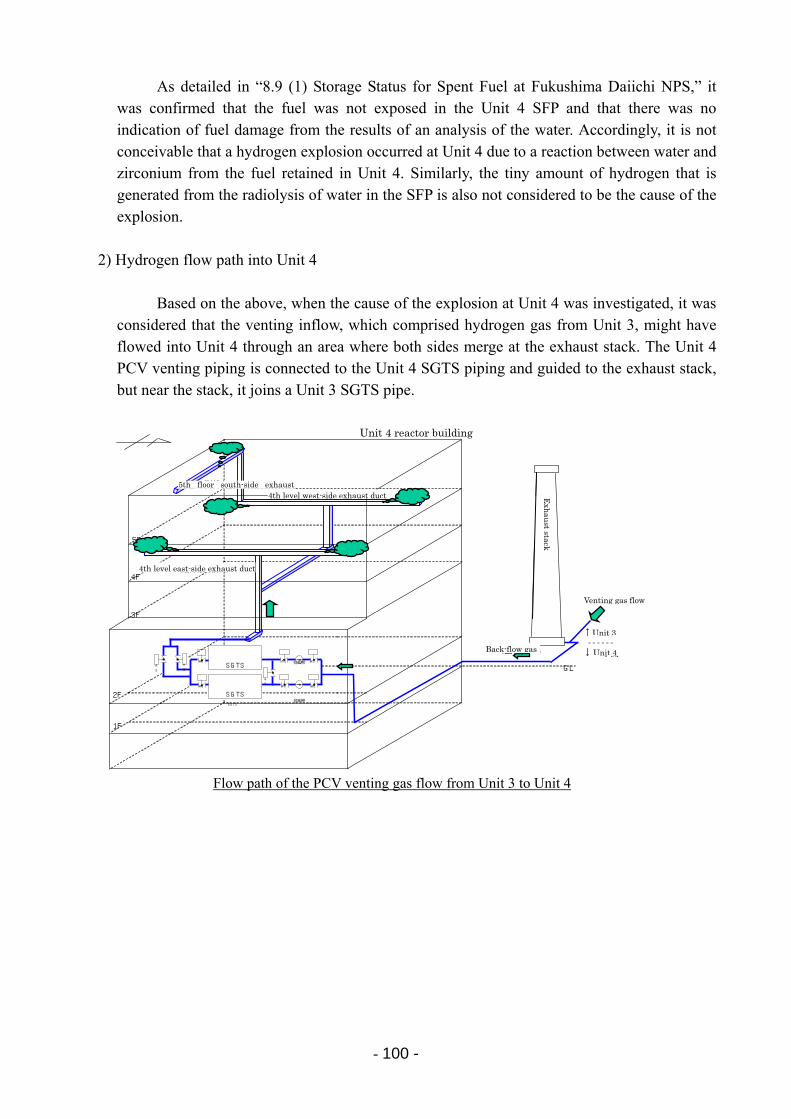
- 100 -
As detailed in “8.9 (1) Storage Status for Spent Fuel at Fukushima Daiichi NPS,” it was confirmed that the fuel was not exposed in the Unit 4 SFP and that there was no indication of fuel damage from the results of an analysis of the water. Accordingly, it is not conceivable that a hydrogen explosion occurred at Unit 4 due to a reaction between water and zirconium from the fuel retained in Unit 4. Similarly, the tiny amount of hydrogen that is generated from the radiolysis of water in the SFP is also not considered to be the cause of the explosion.
2) Hydrogen flow path into Unit 4
Based on the above, when the cause of the explosion at Unit 4 was investigated, it was considered that the venting inflow, which comprised hydrogen gas from Unit 3, might have flowed into Unit 4 through an area where both sides merge at the exhaust stack. The Unit 4 PCV venting piping is connected to the Unit 4 SGTS piping and guided to the exhaust stack, but near the stack, it joins a Unit 3 SGTS pipe.
Flow path of the PCV venting gas flow from Unit 3 to Unit 4
AO
A O AO
AO
AO
AO
AO
排風機
排風機
AO
AO
SGTS
SGTS
SGTS
SGTS
↑3 号機 ------ ↓4号機
1F
3F
4F
5F
GL
2F
4 階東側排気ダクト
5 階南側排気ダクト 4 階西側排気ダクト
ベントガス流
逆流ガス
排
気
筒
Venting gas flow
Unit 4 reactor building
4th level east-side exhaust duct
4th level west-side exhaust duct5th floor south-side exhaust
Back-flow gas Unit 4
Unit 3
Exh
aust stack
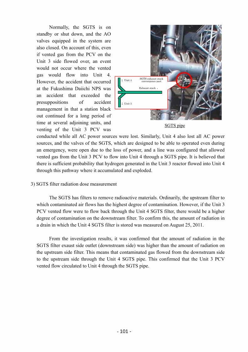
- 101 -
Normally, the SGTS is on standby or shut down, and the AO valves equipped in the system are also closed. On account of this, even if vented gas from the PCV on the Unit 3 side flowed over, an event would not occur where the vented gas would flow into Unit 4. However, the accident that occurred at the Fukushima Daiichi NPS was an accident that exceeded the presuppositions of accident management in that a station black out continued for a long period of time at several adjoining units, and venting of the Unit 3 PCV was conducted while all AC power sources were lost. Similarly, Unit 4 also lost all AC power sources, and the valves of the SGTS, which are designed to be able to operated even during an emergency, were open due to the loss of power, and a line was configured that allowed vented gas from the Unit 3 PCV to flow into Unit 4 through a SGTS pipe. It is believed that there is sufficient probability that hydrogen generated in the Unit 3 reactor flowed into Unit 4 through this pathway where it accumulated and exploded.
3) SGTS filter radiation dose measurement
The SGTS has filters to remove radioactive materials. Ordinarily, the upstream filter to which contaminated air flows has the highest degree of contamination. However, if the Unit 3 PCV vented flow were to flow back through the Unit 4 SGTS filter, there would be a higher degree of contamination on the downstream filter. To confirm this, the amount of radiation in a drain in which the Unit 4 SGTS filter is stored was measured on August 25, 2011.
From the investigation results, it was confirmed that the amount of radiation in the
SGTS filter exaust side outlet (downstream side) was higher than the amount of radiation on the upstream side filter. This means that contaminated gas flowed from the downstream side to the upstream side through the Unit 4 SGTS pipe. This confirmed that the Unit 3 PCV vented flow circulated to Unit 4 through the SGTS pipe.
SGTS pipe
↓3号機
↑4号機
排気筒→
SGTS排気管合流部Unit 4
Unit 3
Exhaust stack
SGTS exhaust stack convergence part
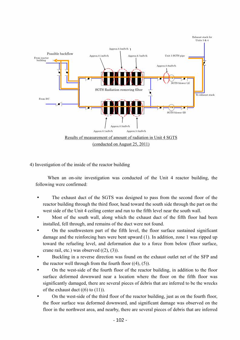
- 102 -
4) Investigation of the inside of the reactor building
When an on-site investigation was conducted of the Unit 4 reactor building, the
following were confirmed:
The exhaust duct of the SGTS was designed to pass from the second floor of the reactor building through the third floor, head toward the south side through the part on the west side of the Unit 4 ceiling center and run to the fifth level near the south wall.
Most of the south wall, along which the exhaust duct of the fifth floor had been installed, fell through, and remains of the duct were not found.
On the southwestern part of the fifth level, the floor surface sustained significant damage and the reinforcing bars were bent upward (1). In addition, zone 1 was ripped up toward the refueling level, and deformation due to a force from below (floor surface, crane rail, etc.) was observed ((2), (3)).
Buckling in a reverse direction was found on the exhaust outlet net of the SFP and the reactor well through from the fourth floor ((4), (5)).
On the west-side of the fourth floor of the reactor building, in addition to the floor surface deformed downward near a location where the floor on the fifth floor was significantly damaged, there are several pieces of debris that are inferred to be the wrecks of the exhaust duct ((6) to (11)).
On the west-side of the third floor of the reactor building, just as on the fourth floor, the floor surface was deformed downward, and significant damage was observed on the floor in the northwest area, and nearby, there are several pieces of debris that are inferred
Results of measurement of amount of radiation in Unit 4 SGTS
(conducted on August 25, 2011)
非常用ガス処理系排風機(B)
非常用ガス処理系放射能除去フィルタ
圧力抑制室より
排気筒へ
原子炉建屋より
3号機非常用ガス処理系排気管
3/4号機排気筒
逆流の可能性あり 約0.1mSv/h
約0.5mSv/h
約6.7mSv/h
約0.8mSv/h
非常用ガス処理系排風機(A)
約0.1mSv/h
約0.5mSv/h
約5.5mSv/h
From reactor building
From S/C
Exhaust stack for Units 3 & 4
Unit 3 SGTS pipe
SGTS blower (B)
SGTS blower (A)
To exhaust stack
SGTS Radiation removing filter
Possible backflow Approx.0.1mSv/h
Approx.0.5mSv/h
Approx.6.7mSv/h
Approx.0.8mSv/h
Approx.0.5mSv/h
Approx.0.1mSv/h Approx.5.5mSv/h
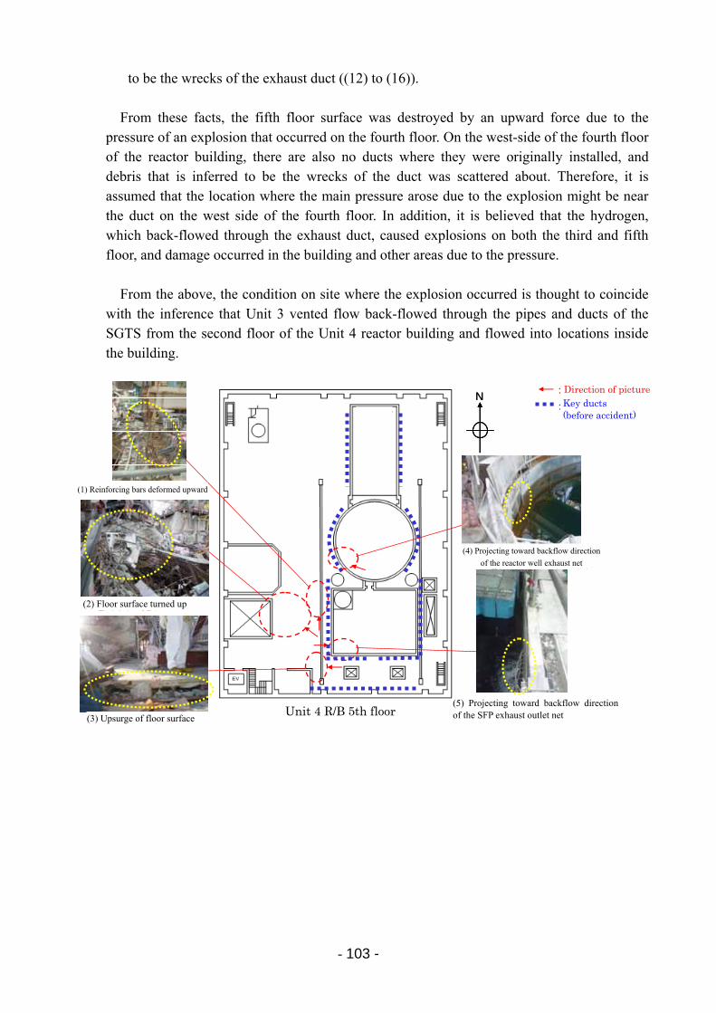
- 103 -
to be the wrecks of the exhaust duct ((12) to (16)).
From these facts, the fifth floor surface was destroyed by an upward force due to the pressure of an explosion that occurred on the fourth floor. On the west-side of the fourth floor of the reactor building, there are also no ducts where they were originally installed, and debris that is inferred to be the wrecks of the duct was scattered about. Therefore, it is assumed that the location where the main pressure arose due to the explosion might be near the duct on the west side of the fourth floor. In addition, it is believed that the hydrogen, which back-flowed through the exhaust duct, caused explosions on both the third and fifth floor, and damage occurred in the building and other areas due to the pressure.
From the above, the condition on site where the explosion occurred is thought to coincide
with the inference that Unit 3 vented flow back-flowed through the pipes and ducts of the SGTS from the second floor of the Unit 4 reactor building and flowed into locations inside the building.
4号機 R/B 5階
NN
③床面の盛り上がり
①上方向に変形した鉄筋
②床面の捲れ上がり
⑤使用済燃料プール排気口ネットの逆流方向への張り出し
:撮影方向
:主なダクト(事故前)
④原子炉ウェル排気口ネットの逆流方向への張り出し
(1) Reinforcing bars deformed upward
(2) Floor surface turned up
(3) Upsurge of floor surface
(5) Projecting toward backflow direction of the SFP exhaust outlet net
(4) Projecting toward backflow direction
of the reactor well exhaust net
Unit 4 R/B 5th floor
Direction of picture Key ducts (before accident)
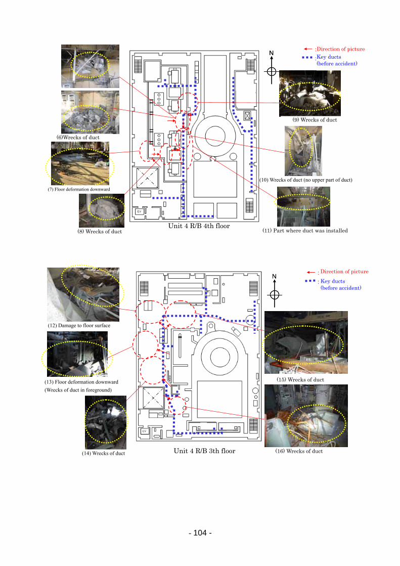
- 104 -
4号機 R/B 4階
NN
⑦床面の下方への変形
:撮影方向
⑧ダクトの残骸 ⑪ダクトが設置されていた部分
:主なダクト(事故前)
⑥ダクトの残骸
⑩ダクトの残骸(上部ダクトなし)
⑨ダクトの残骸
Direction of picture Key ducts (before accident)
(6)Wrecks of duct
(7) Floor deformation downward
(8) Wrecks of duct
(9) Wrecks of duct
(10) Wrecks of duct (no upper part of duct)
(11) Part where duct was installed Unit 4 R/B 4th floor
4号機 R/B 3階
NN:撮影方向
:主なダクト(事故前)
⑭ダクトの残骸
⑬床面の下方への変形(手前はダクトの残骸)
⑫床面の損傷
⑯ダクトの残骸
⑮ダクトの残骸
Direction of picture
Key ducts (before accident)
(12) Damage to floor surface
(13) Floor deformation downward
(Wrecks of duct in foreground)
Unit 4 R/B 3th floor (14) Wrecks of duct
(15) Wrecks of duct
(16) Wrecks of duct
- 105 -
10 Analysis of the Accident and Identification of Major Issues 10.1 Issues concerning plant behavior at the time of the accident
In this section, the information that has been collected at this time, including post analysis results based on this information are described. The plants subject to this analysis were Fukushima Daiichi Units 1 to 3, which sustained core damage, and Fukushima Daini Unit 1, which achieved cold shutdown due to prompt responses, such as the restoration of the temporary power supply for the emergency seawater system, etc.
For Fukushima Daiichi Units 1 to 3, the core status was evaluated using the accident analysis code (Modular Accident Analysis Program; hereinafter referred to as “MAAP”), based on information regarding the equipment status and operation during the initial stages after the earthquake, etc.
(1) Plant behavior of Fukushima Daiichi Unit 1
1) Evaluation of behavior by analysis
The event progression at Fukushima Daiichi Unit 1 is described in this section discussing the analysis results from the MAAP code and the measured data (actual values) for the reactor water level, reactor pressure, and the amount of hydrogen generated.
In the analysis, it is assumed that the IC was intermittently operated in accordance with
changes in the reactor pressure until the arrival of the tsunami and was not operated after the tsunami attack. Therefore, the reactor cooling water was evaporated and was emitted from the SRV to the S/C, causing the reactor water level to start decreasing.
In the analysis, the reactor water level reached the TAF approximately 3 hours after the earthquake (March 11, 14:46). The fuel temperature exceeded 1200°C and core damage started approximately 4 hours after the earthquake. The water level continued to decrease and dropped to the bottom of Active Fuel (BAF) at around 20:00 on March 11.
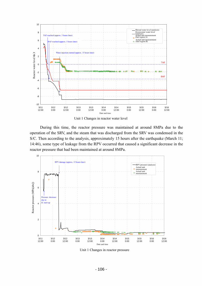
- 106 -
During this time, the reactor pressure was maintained at around 8MPa due to the
operation of the SRV, and the steam that was discharged from the SRV was condensed in the S/C. Then according to the analysis, approximately 15 hours after the earthquake (March 11; 14:46), some type of leakage from the RPV occurred that caused a significant decrease in the reactor pressure that had been maintained at around 8MPa.
0
2
4
6
8
10
3/11 12:00
3/12 0:00
3/12 12:00
3/13 0:00
3/13 12:00
3/14 0:00
3/14 12:00
3/15 0:00
3/15 12:00
3/16 0:00
3/16 12:00
日時
原子炉圧力(MPa[abs])
RPV圧力( 解析)
実機計測値( A系)
実機計測値( B系)
IC起動による圧力低下
RPV破損(約15時間後)
Unit 1 Changes in reactor pressure
RPV pressure (analysis) Actual unit measurement Actual unit measurement
RPV damage (approx. 15 hours later)
Pressure decrease due to IC start-up
Date and time
Rea
ctor
pre
ssur
e (M
Pa[
abs]
)
-10
-8
-6
-4
-2
0
2
4
6
8
10
3/11 12:00
3/12 0:00
3/12 12:00
3/13 0:00
3/13 12:00
3/14 0:00
3/14 12:00
3/15 0:00
3/15 12:00
3/16 0:00
3/16 12:00
日時
原子炉水位(m)
シュラウド内水位(解析)
ダウンカマ水位(解析)
実機計測値(燃料域A)
実機計測値(燃料域B)
TAF到達(約3時間後)
BAF到達(約5時間後)
注水開始(約15時間後)
TAF
BAF
Unit 1 Changes in reactor water level
TAF reached (approx. 3 hours later)
BAF reached (approx. 5 hours later)
Water injection started (approx. 15 hours later)
Actual unit measurement (fuel region B)
Downcomer water level (analysis)
Shroud water level (analysis)
Rea
ctor
wat
er le
vel(
m)
Date and time
Actual unit measurement (fuel region A)
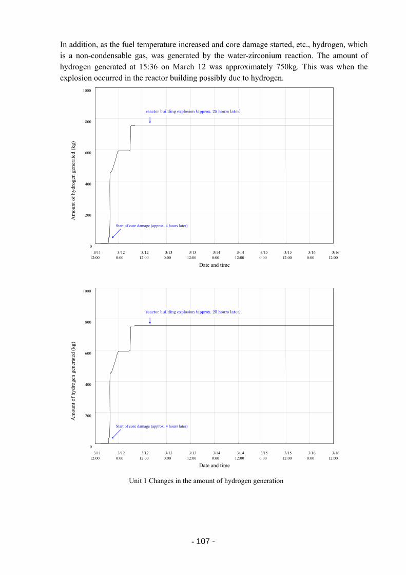
- 107 -
In addition, as the fuel temperature increased and core damage started, etc., hydrogen, which is a non-condensable gas, was generated by the water-zirconium reaction. The amount of hydrogen generated at 15:36 on March 12 was approximately 750kg. This was when the explosion occurred in the reactor building possibly due to hydrogen.
Unit 1 Changes in the amount of hydrogen generation
0
200
400
600
800
1000
3/11 12:00
3/12 0:00
3/12 12:00
3/13 0:00
3/13 12:00
3/14 0:00
3/14 12:00
3/15 0:00
3/15 12:00
3/16 0:00
3/16 12:00
Date and time
Start of core damage (approx. 4 hours later)
Am
ount
of
hydr
ogen
gen
erat
ed (
kg)
reactor building explosion (approx. 25 hours later)
0
200
400
600
800
1000
3/11 12:00
3/12 0:00
3/12 12:00
3/13 0:00
3/13 12:00
3/14 0:00
3/14 12:00
3/15 0:00
3/15 12:00
3/16 0:00
3/16 12:00
Date and time
Start of core damage (approx. 4 hours later)
Am
ount
of
hydr
ogen
gen
erat
ed (
kg)
reactor building explosion (approx. 25 hours later)
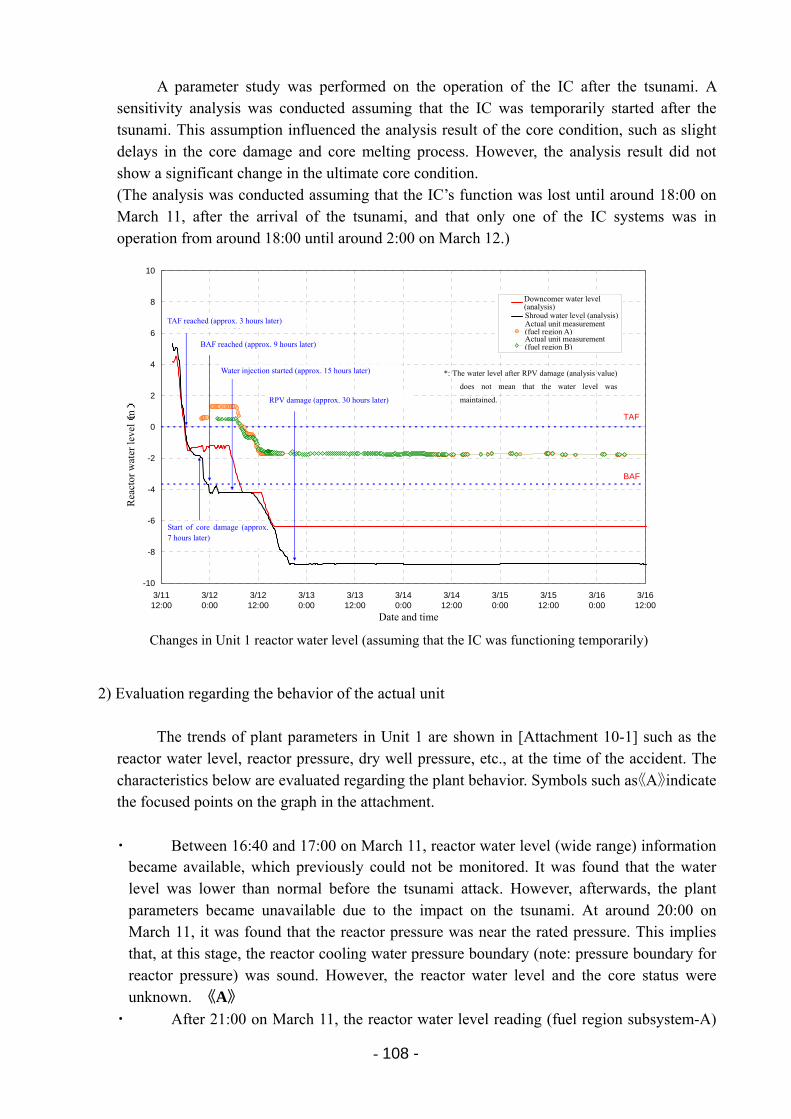
- 108 -
-10
-8
-6
-4
-2
0
2
4
6
8
10
3/11 12:00
3/12 0:00
3/12 12:00
3/13 0:00
3/13 12:00
3/14 0:00
3/14 12:00
3/15 0:00
3/15 12:00
3/16 0:00
3/16 12:00
日時
原子炉水位(m)
ダウンカマ水位(解析)
シュラウド内水位(解析)
実機計測値(燃料域A)
実機計測値(燃料域B)
TAF到達(約3時間後)
BAF到達(約9時間後)
TAF
BAF
注水開始(約15時間後)
炉心損傷開始(約7時間後)
RPV破損(約30時間後)
A parameter study was performed on the operation of the IC after the tsunami. A sensitivity analysis was conducted assuming that the IC was temporarily started after the tsunami. This assumption influenced the analysis result of the core condition, such as slight delays in the core damage and core melting process. However, the analysis result did not show a significant change in the ultimate core condition. (The analysis was conducted assuming that the IC’s function was lost until around 18:00 on March 11, after the arrival of the tsunami, and that only one of the IC systems was in operation from around 18:00 until around 2:00 on March 12.)
2) Evaluation regarding the behavior of the actual unit
The trends of plant parameters in Unit 1 are shown in [Attachment 10-1] such as the reactor water level, reactor pressure, dry well pressure, etc., at the time of the accident. The characteristics below are evaluated regarding the plant behavior. Symbols such as《A》indicate the focused points on the graph in the attachment.
・ Between 16:40 and 17:00 on March 11, reactor water level (wide range) information became available, which previously could not be monitored. It was found that the water level was lower than normal before the tsunami attack. However, afterwards, the plant parameters became unavailable due to the impact on the tsunami. At around 20:00 on March 11, it was found that the reactor pressure was near the rated pressure. This implies that, at this stage, the reactor cooling water pressure boundary (note: pressure boundary for reactor pressure) was sound. However, the reactor water level and the core status were unknown. 《A》
・ After 21:00 on March 11, the reactor water level reading (fuel region subsystem-A)
*: The water level after RPV damage (analysis value)
does not mean that the water level was
maintained.
Changes in Unit 1 reactor water level (assuming that the IC was functioning temporarily)
Shroud water level (analysis)
Downcomer water level (analysis)
Actual unit measurement (fuel region A) Actual unit measurement (fuel region B)
TAF reached (approx. 3 hours later)
BAF reached (approx. 9 hours later)
Water injection started (approx. 15 hours later)
RPV damage (approx. 30 hours later)
Start of core damage (approx. 7 hours later)
Rea
ctor
wat
er le
vel(
m)
Date and time
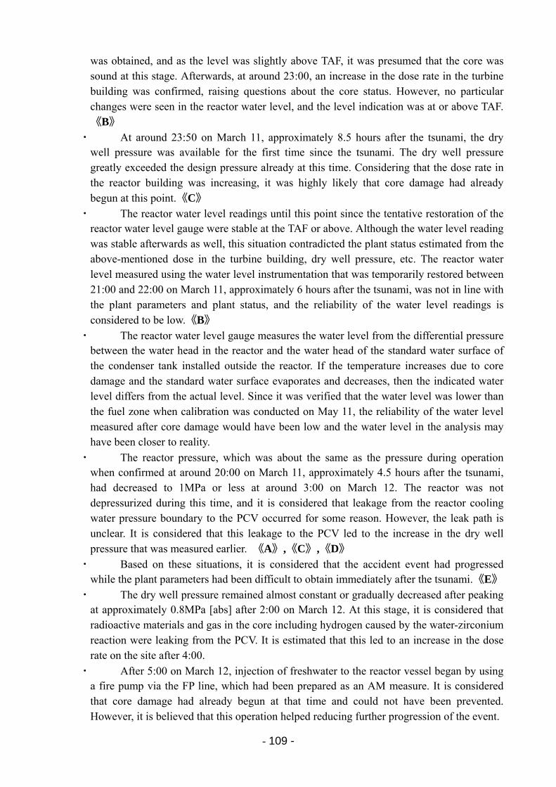
- 109 -
was obtained, and as the level was slightly above TAF, it was presumed that the core was sound at this stage. Afterwards, at around 23:00, an increase in the dose rate in the turbine building was confirmed, raising questions about the core status. However, no particular changes were seen in the reactor water level, and the level indication was at or above TAF. 《B》
・ At around 23:50 on March 11, approximately 8.5 hours after the tsunami, the dry well pressure was available for the first time since the tsunami. The dry well pressure greatly exceeded the design pressure already at this time. Considering that the dose rate in the reactor building was increasing, it was highly likely that core damage had already begun at this point.《C》
・ The reactor water level readings until this point since the tentative restoration of the reactor water level gauge were stable at the TAF or above. Although the water level reading was stable afterwards as well, this situation contradicted the plant status estimated from the above-mentioned dose in the turbine building, dry well pressure, etc. The reactor water level measured using the water level instrumentation that was temporarily restored between 21:00 and 22:00 on March 11, approximately 6 hours after the tsunami, was not in line with the plant parameters and plant status, and the reliability of the water level readings is considered to be low.《B》
・ The reactor water level gauge measures the water level from the differential pressure between the water head in the reactor and the water head of the standard water surface of the condenser tank installed outside the reactor. If the temperature increases due to core damage and the standard water surface evaporates and decreases, then the indicated water level differs from the actual level. Since it was verified that the water level was lower than the fuel zone when calibration was conducted on May 11, the reliability of the water level measured after core damage would have been low and the water level in the analysis may have been closer to reality.
・ The reactor pressure, which was about the same as the pressure during operation when confirmed at around 20:00 on March 11, approximately 4.5 hours after the tsunami, had decreased to 1MPa or less at around 3:00 on March 12. The reactor was not depressurized during this time, and it is considered that leakage from the reactor cooling water pressure boundary to the PCV occurred for some reason. However, the leak path is unclear. It is considered that this leakage to the PCV led to the increase in the dry well pressure that was measured earlier. 《A》,《C》,《D》
・ Based on these situations, it is considered that the accident event had progressed while the plant parameters had been difficult to obtain immediately after the tsunami.《E》
・ The dry well pressure remained almost constant or gradually decreased after peaking at approximately 0.8MPa [abs] after 2:00 on March 12. At this stage, it is considered that radioactive materials and gas in the core including hydrogen caused by the water-zirconium reaction were leaking from the PCV. It is estimated that this led to an increase in the dose rate on the site after 4:00.
・ After 5:00 on March 12, injection of freshwater to the reactor vessel began by using a fire pump via the FP line, which had been prepared as an AM measure. It is considered that core damage had already begun at that time and could not have been prevented. However, it is believed that this operation helped reducing further progression of the event.
- 110 -
At this time, a large amount of hydrogen had filled the PCV following core damage.
Since both the PCV pressure and temperature were high, it is estimated that radioactive material and hydrogen leaked into the reactor building.《F》
・ In order to decrease the PCV pressure, S/C venting was conducted. After 14:00 on March 12, a decrease in the PCV pressure was confirmed, Hence venting was determined to have been successful.《G》
・ Later, at 15:36 on March 12, the reactor building exploded. This is presumed to have occurred due to the accumulation of hydrogen in the reactor building generated as a result of core damage and being ignited by some source.
・ The dose rate measured near the main gate using a monitoring car temporarily increased at the time of S/C venting. However, the increase in background level was much lower than the high values since March 14. Hence, it is estimated that the temporary increase in dose rate was mainly due to noble gases.
3) Analysis on the IC
Based on the analysis on the plant behavior described in the previous section, it is
considered that core damage had progressed in a short period of time after the tsunami. Hence, the status of the IC, which is used to cool the reactor in the initial stages after shutdown, might have affected the event progression.
The analysis on the event focusing on the IC is as follows:
Reference: Outline of the IC (refer to [Attachment 10-2] for the composition)
・ The isolation condensers cool the reactor when the reactor is isolated and work by extracting
steam from the reactor and cool steam by exchanging heat with the cooling water stored in the
isolation condensers, turning it back into water and returning it to the reactor. The isolation
condenser is installed only in Unit 1 of Fukushima Daiichi.
・ There are two trains of the IC (subsystem-A and subsystem-B), and the pipes that circulate the
reactor steam are composed of four valves. Two valves each are installed at the entrance and exit
of each isolation condenser, on both sides of the containment vessel. The two valves inside the
containment vessel are activated by AC power and the other two valves outside the containment
are activated by DC power.
・ Normally, one of the valves on the exit side of the isolation condenser and outside the
containment vessel (3A valve, 3B valve) is closed, and the other valves are on standby in the fully
open position. Startup and shutdown of the IC is conducted by opening and closing these 3A
valve and 3B valves.
・ Reactor pressure can be controlled by intermittently opening and closing the valves.
- 111 -
<Facts on the IC operation>
March 11, 14:52; Automatic startup of the IC As the power of the emergency main bus was lost following the loss of off-site power, the MSIVs were automatically closed and the two IC systems were automatically started up by “high reactor pressure (7.13 MPa [gage]).” As the depressurization and cooling of the reactor was started, the reactor pressure began to decrease.
Around 15:03; Manual shutdown of the IC The decrease in reactor pressure following the IC startup was fast. It was determined that it would exceed the decreasing rate of 55 degrees C/h for the RPV temperature that is stipulated in the operating procedures. Therefore, the return pipe containment isolation valve (MO-3A, 3B) of the IC was “fully closed” for the moment. The other valves were in the open position and were in the usual standby status. This caused the reactor pressure to increase again. Later, it was determined that one IC system would be enough to keep the reactor pressure at about 6-7MPa. It was decided to use the subsystem-A, and the operation to control the reactor pressure by the opening and closing of the return pipe containment isolation valve (MO-3A) was started.
15:37; Loss of power Due to the tsunami flooding, Unit 1 lost all the AC power, as well as the DC power. Therefore, the lights of the MCR as well as the monitoring devices and various indicator lights were lost, and it was not possible to confirm the valve positions of, or to operate, the IC.
Around 16:42; Temporary restoration of the water level gauge Between around 16:40 and 17:00 on March 11, reactor water level (wide range) information became temporarily available (the indicated level was equivalent to TAF (top of active fuel) +250 cm at 16:42), which had not been able to be monitored until then. It was found that the water level was lower than the level observed before the arrival of the tsunami.
17:19; Attempt for verification of the IC in the field Since it was not possible to check the status of the IC from the MCR, it was decided to check the water level gauge for the shell-side water (cooling water) of the IC in the field where the IC was installed. Although an operator headed to the field, since the dose rate level in the field (the entrance of the reactor building) was higher than usual, he headed back from the field at 17:50 for the moment.
18:18; Restoration of the DC power for the outer side containment isolation valve of subsystem-A/ opening of the outer side containment isolation valve of subsystem-A
Some of the DC power was restored, maybe due to the temporarily unstable condition of the DC power caused by the impacts of the tsunami. An operator found that green lights were blinking (DC), which indicated that the supply pipe containment isolation valve (MO-2A) and the return pipe containment isolation valve (MO-3A) of the IC (subsystem-A) were “closed.” Since the supply pipe containment isolation valve (MO-2A) of the IC, which is usually in the open position, was closed, it was considered that a “IC pipe rupture” signal had been sent as an operation on the safe side following the loss of DC
- 112 -
power to detect “IC pipe rupture,” and all the containment isolation valves of the IC were closed. However, the operator expected that the containment isolation valves inside the PCV (MO-1A, 4A) might be open, and he attempted to open the return pipe containment isolation valve (MO-3A) and the supply pipe containment isolation valve (MO-2A) of the IC at 18:18. The status display light turned from “closed” to “open.” As the monitoring devices were not in operation due to the loss of power, the operator had no means to verify that the IC was activated. Thus, the operator confirmed that steam was being generated from the IC vent pipes after the opening of the valves (that clean water that had cooled the reactor steam was vaporized and released into the air) by the sound of steam generation and the fact that steam was observed over the reactor building.
18:25; Closing of the subsystem-A outer side containment isolation valve Since the steam generation stopped after a while, the return pipe containment isolation valve (MO-3A) of the IC was closed and the operation of IC was stopped. As an action that could be performed from the MCR, the configuration of the line for water injection into the reactor using the FP line was in progress. Amidst a series of unpredictable events, while the operator considered as a cause for the halt of steam generation that the containment isolation valves inside the PCV (MO-1A, 4A) had been closed by the isolation signal, he was concerned about the possibility that the shell-side water of the IC, which was the cooling water, was gone for some reason. Considering that the IC was not functioning and also taking into account the fact that the pipes necessary to replenish water to the shell-side were not configured yet, the operator closed the return pipe containment isolation valve (MO-3A) for the moment.
Around 20:50; Configuration of the line for water injection into the reactor using the FP line The configuration of the line for water injection into the reactor using the FP line was completed, and the diesel-driven fire pump was started up. This enabled the cooling water on the shell-side of the IC to be replenished. When an operator checked the operating condition of the IC, he confirmed that the display light for the closing status of the IC return pipe containment isolation valve (MO-3A) was unstable and was fading.
21:19; Temporary restoration of the reactor water level gauge Reactor water level information became available, which had not been able to be monitored. The instrument indicated the water level of TAF +200mm.
Around 21:30; Opening of the 3A valve (subsystem-A startup) Although the reactor water level was above the fuel, the power for the steam-driven HPCI pump was lost and the pump could not be started up, and at this point, the IC was the only cooling device of the high-pressure systems that could be expected to function. As the IC could normally be operated for about 10 hours without water supply from the shell-side, and because water could be supplied to the IC shell-side as the diesel-driven fire pump had started up, there was less concern for the lack of water on the shell-side. On the other hand, it was not clear when the IC could next be operated. Taking all of these into account, under an expectation that the IC, the cooling device of the high-pressure systems, could be activated, the return pipe containment isolation valve (MO-3A), which was temporarily closed, was opened again at around 21:30. The valve opened, and steam generation was confirmed by the sound of steam generation and steam was observed over the reactor building. The steam generation was also confirmed by the plant operation team of the ERC
- 113 -
from outside of the seismic isolated building. March 29; Restoration of the shell-side water level gauge of the IC
The shell-side water level gauge of the IC was restored. April 1; Confirmation of the valve position using the valve control circuit of the IC
As a part of restoration work, the valve position was confirmed based on the conductive status of the control circuit for the valves of the IC. The status of valves inside the PCV could not be confirmed due to the influence of the accident such as heating at the time of the accident. However, the valve position of the valves outside the PCV was able to be determined. The 3A and 2A valves of the IC (subsystem-A) were open. The 3B and 2B valves of the IC (subsystem-B) were closed.
April 3; Shell-side water level check of the IC When the water level gauge reading of the IC was investigated in the MCR, the indication for the subsystem-A was 63% and the subsystem-B was 83%.
October 18; Field survey The status of the outer side of the PCV of the IC was confirmed by a visual check in the field. No damage was found to its main units and main pipes. The valve status was the same as the results of the circuit investigation on April 1. It was found that the field water level gauge of the IC was 65% for the subsystem-A and 85% for the subsystem-B, which matched the instrument readings confirmed in the MCR on the same day.
The analysis is shown below based on the above-described facts and the previously provided analysis results.
<Evaluation regarding IC operation immediately after the earthquake>
・ As mentioned in "6.2 Plant status immediately after the earthquake," the decrease rate of the RPV temperature has to be controlled so that it would not exceed 55°C/h from the perspective of RPV protection according to the procedure. As pressure control was conducted manually and properly based on the procedures, it was considered that there was no any problem either in terms of equipment or in terms of operation.
<Status of IC valves after the tsunami>
・ The status of the valves at the time of tsunami arrival is considered to be, based on the operations conducted until the tsunami, that the 3A valve of the IC (subsystem-A) was closed, and the other three valves were fully open. For the subsystem-B, the 3B valve was closed, and the other three valves were fully open.
・ In addition, for subsystem-A, it was confirmed at around 18:18 that the 2A valve that had not been operated was fully closed. Also, for the subsystem-B, it was confirmed that the 2B valve that had not been operated was also fully closed, based on the results of the valve circuit investigation that was conducted on April 1. This was also confirmed by the position meter of the valve in the field on October 18. Therefore, it was confirmed that both the 2A and 2B valves had been open until the tsunami, and were closed afterwards although no operation was conducted on them.
- 114 -
・ The operations of the 2A and 2B valves until the first shutdown operation can be confirmed by the open-shut record of the system to record transient events. It is unlikely that an operator mistakenly operated the valves. Meanwhile, based on the configuration of the logic circuit, when the DC power of the logic circuit is lost, an interlocking operation is activated, and all four valves of each IC system are designed to be fully closed automatically due to the interlocking operation. In the case of this accident, it is considered that the DC power of the logic circuit was lost due to the tsunami and the interlocking signal for the valve close operations was activated. [Attachment 10-3]
・ The time required to fully close a valve from a fully-open position is within 15 seconds for an outer valve and within 20 seconds for an inner valve. If the DC power is lost due to the water damage caused by the tsunami, the valves automatically close during the time between when the DC power for instruments is affected by tsunami flooding that leads to the activation of interlocking operation, and when the DC power for valve operation is lost.
・ If the DC power for operation was lost during a valve closing operation, the valve would be half-open. However, as mentioned before, it was confirmed that the 2A and 2B valves were completely closed. Consequently it is highly probable that the IC valves automatically and fully closed, before the DC valve operating power was lost, in response to the isolation signal due to water damage by tsunami flooding to the power panels.
・ The valves inside the PCV are operated on AC power. The valve position of these valves would be determined according to the timing of the loss of DC power for instruments and the loss of AC power. While it is not possible to specify the valve position of the valves inside the PCV, any status from fully open to fully closed can be possible.
・ The above described analysis indicates that the operational state of the IC before the tsunami does not determine the operational state of the IC after the tsunami.
[Attachment 10-4] <Relationship with the core damage>
・ Since the automatic isolation interlock of the IC was actuated due to the loss of power caused by the tsunami, thereby causing the IC to become inoperable, the IC lost its function. According to the MAAP analysis result, because this happened immediately after the reactor shutdown with high decay heat, it is considered that the reactor water level decreased in a short period of time, leading to the exposure of core (Dropped to TAF at around 17:46).
・ Later, the DC power to the IC (subsystem-A) was restored, and at 18:18, the containment isolation valves (3A valve, 2A valve) of the IC (A) were opened, and it was confirmed that steam was being generated. After steam generation stopped, the 3A valve was closed at 18:25. Based on the analysis results of the MAAP, the core was already exposed at this time, and it is evaluated that the core was ultimately damaged regardless of whether or not the operation of the IC was continued after 18:18.
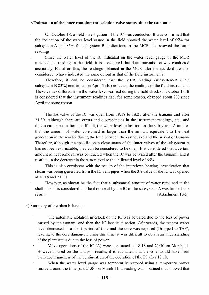
- 115 -
<Estimation of the inner containment isolation valve status after the tsunami>
・ On October 18, a field investigation of the IC was conducted. It was confirmed that the indication of the water level gauge in the field showed the water level of 65% for subsystem-A and 85% for subsystem-B. Indications in the MCR also showed the same readings
・ Since the water level of the IC indicated on the water level gauge of the MCR matched the reading in the field, it is considered that data transmission was conducted accurately. Based on this, the readings obtained in the MCR after the accident are also considered to have indicated the same output as that of the field instruments.
・ Therefore, it can be considered that the MCR reading (subsystem-A 63%; subsystem-B 83%) confirmed on April 3 also reflected the readings of the field instruments. These values differed from the water level verified during the field check on October 18. It is considered that the instrument readings had, for some reason, changed about 2% since April for some reason.
・ The 3A valve of the IC was open from 18:18 to 18:25 after the tsunami and after 21:30. Although there are errors and discrepancies in the instrument readings, etc., and thus accurate estimation is difficult, the water level indication for the subsystem-A implies that the amount of water consumed is larger than the amount equivalent to the heat generation in the reactor during the time between the earthquake and the arrival of tsunami. Therefore, although the specific open-close status of the inner valves of the subsystem-A has not been estimatable, they can be considered to be open. It is considered that a certain amount of heat removal was conducted when the IC was activated after the tsunami, and it resulted in the decrease in the water level to the indicated level of 65%.
・ This is also consistent with the results of the interviews hearing investigation that steam was being generated from the IC vent pipes when the 3A valve of the IC was opened at 18:18 and 21:30.
・ However, as shown by the fact that a substantial amount of water remained in the shell-side, it is considered that heat removal by the IC of the subsystem-A was limited as a result. [Attachment 10-5]
4) Summary of the plant behavior
・ The automatic isolation interlock of the IC was actuated due to the loss of power caused by the tsunami and then the IC lost its function. Afterwards, the reactor water level decreased in a short period of time and the core was exposed (Dropped to TAF), leading to the core damage. During this time, it was difficult to obtain an understanding of the plant status due to the loss of power.
・ Valve operations of the IC (A) were conducted at 18:18 and 21:30 on March 11. However, based on the analysis results, it is evaluated that the core would have been damaged regardless of the continuation of the operation of the IC after 18:18.
・ When the water level gauge was temporarily restored using a temporary power source around the time past 21:00 on March 11, a reading was obtained that showed that
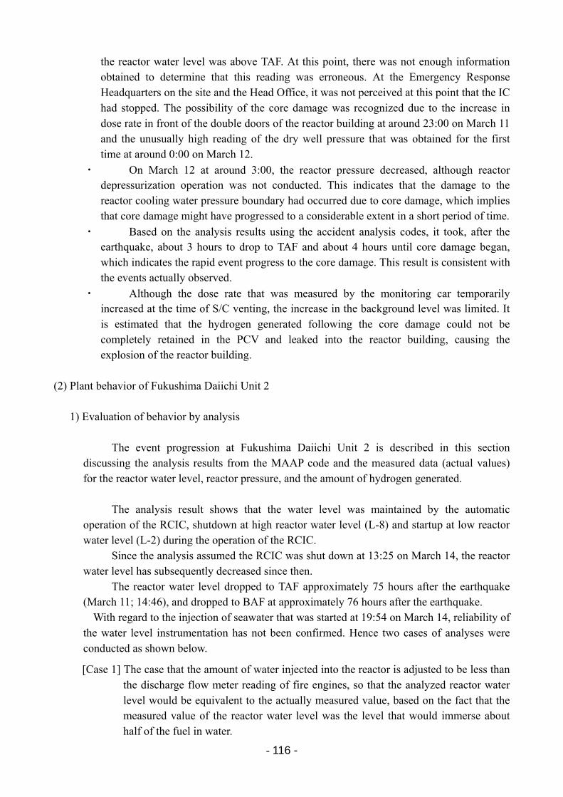
- 116 -
the reactor water level was above TAF. At this point, there was not enough information obtained to determine that this reading was erroneous. At the Emergency Response Headquarters on the site and the Head Office, it was not perceived at this point that the IC had stopped. The possibility of the core damage was recognized due to the increase in dose rate in front of the double doors of the reactor building at around 23:00 on March 11 and the unusually high reading of the dry well pressure that was obtained for the first time at around 0:00 on March 12.
・ On March 12 at around 3:00, the reactor pressure decreased, although reactor depressurization operation was not conducted. This indicates that the damage to the reactor cooling water pressure boundary had occurred due to core damage, which implies that core damage might have progressed to a considerable extent in a short period of time.
・ Based on the analysis results using the accident analysis codes, it took, after the earthquake, about 3 hours to drop to TAF and about 4 hours until core damage began, which indicates the rapid event progress to the core damage. This result is consistent with the events actually observed.
・ Although the dose rate that was measured by the monitoring car temporarily increased at the time of S/C venting, the increase in the background level was limited. It is estimated that the hydrogen generated following the core damage could not be completely retained in the PCV and leaked into the reactor building, causing the explosion of the reactor building.
(2) Plant behavior of Fukushima Daiichi Unit 2
1) Evaluation of behavior by analysis
The event progression at Fukushima Daiichi Unit 2 is described in this section discussing the analysis results from the MAAP code and the measured data (actual values) for the reactor water level, reactor pressure, and the amount of hydrogen generated.
The analysis result shows that the water level was maintained by the automatic operation of the RCIC, shutdown at high reactor water level (L-8) and startup at low reactor water level (L-2) during the operation of the RCIC.
Since the analysis assumed the RCIC was shut down at 13:25 on March 14, the reactor water level has subsequently decreased since then.
The reactor water level dropped to TAF approximately 75 hours after the earthquake (March 11; 14:46), and dropped to BAF at approximately 76 hours after the earthquake.
With regard to the injection of seawater that was started at 19:54 on March 14, reliability of the water level instrumentation has not been confirmed. Hence two cases of analyses were conducted as shown below.
[Case 1] The case that the amount of water injected into the reactor is adjusted to be less than the discharge flow meter reading of fire engines, so that the analyzed reactor water level would be equivalent to the actually measured value, based on the fact that the measured value of the reactor water level was the level that would immerse about half of the fuel in water.
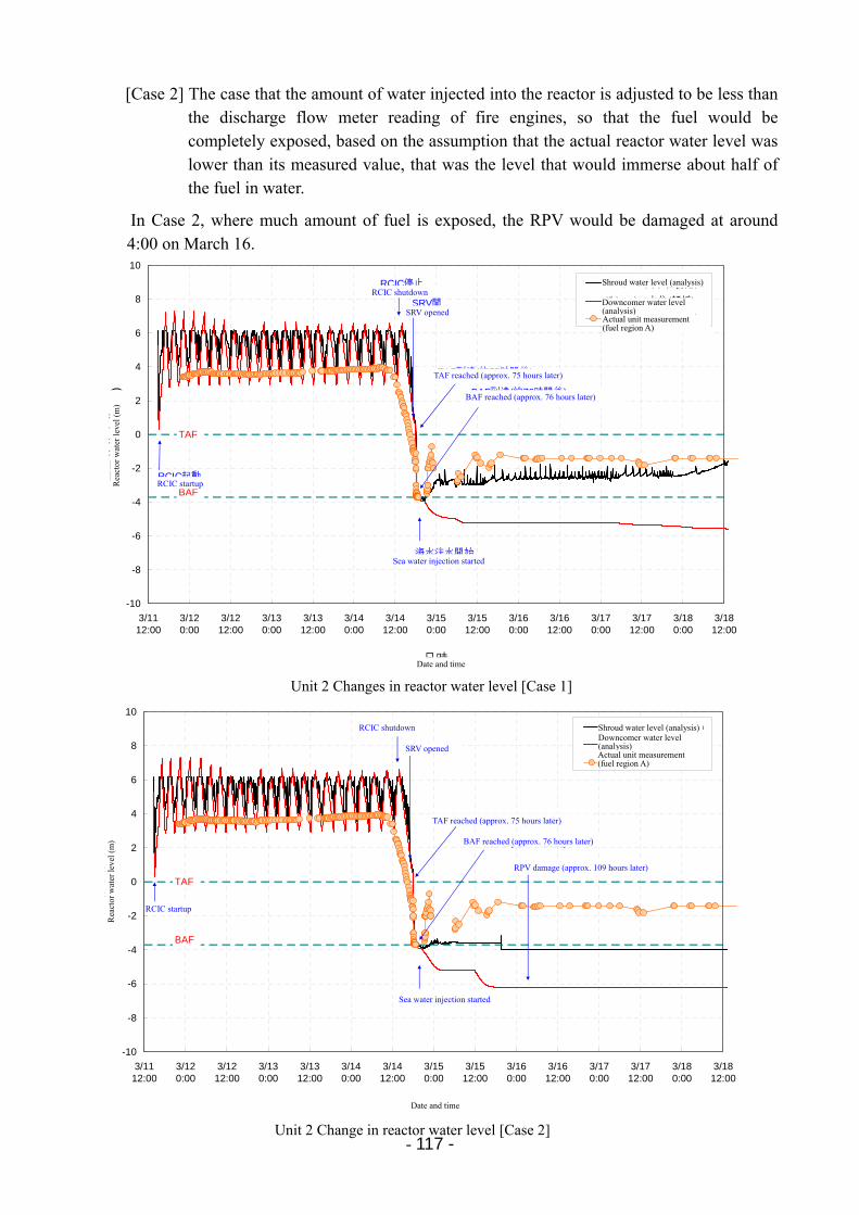
- 117 -
[Case 2] The case that the amount of water injected into the reactor is adjusted to be less than the discharge flow meter reading of fire engines, so that the fuel would be completely exposed, based on the assumption that the actual reactor water level was lower than its measured value, that was the level that would immerse about half of the fuel in water.
In Case 2, where much amount of fuel is exposed, the RPV would be damaged at around 4:00 on March 16.
Unit 2 Changes in reactor water level [Case 1]
-10
-8
-6
-4
-2
0
2
4
6
8
10
3/1112:00
3/120:00
3/1212:00
3/130:00
3/1312:00
3/140:00
3/1412:00
3/150:00
3/1512:00
3/160:00
3/1612:00
3/170:00
3/1712:00
3/180:00
3/1812:00
日時
原子炉炉水位
(m
)
シュラウド内水位(解析)
ダウンカマ水位(解析)
実機計測値(燃料域A)
RCIC起動
RCIC停止
SRV開
海水注水開始
TAF
BAF
TAF到達(約75時間後)
BAF到達(約76時間後)
Rea
ctor
wat
er le
vel (
m)
RCIC startup
RCIC shutdown
SRV opened
TAF reached (approx. 75 hours later)
BAF reached (approx. 76 hours later)
Sea water injection started
Shroud water level (analysis)
Downcomer water level (analysis) Actual unit measurement (fuel region A)
Date and time
Unit 2 Change in reactor water level [Case 2]
-10
-8
-6
-4
-2
0
2
4
6
8
10
3/1112:00
3/120:00
3/1212:00
3/130:00
3/1312:00
3/140:00
3/1412:00
3/150:00
3/1512:00
3/160:00
3/1612:00
3/170:00
3/1712:00
3/180:00
3/1812:00
日時
原子炉水位
(m
)
シュラウド内水位(解析)
ダウンカマ水位(解析)
実機計測値(燃料域A)
RCIC起動
RCIC停止
SRV開
海水注水開始
TAF
BAF
TAF到達(約75時間後)
BAF到達(約76時間後)
RPV破損(約109時間後)
Date and time
RCIC shutdown
SRV opened
TAF reached (approx. 75 hours later)
BAF reached (approx. 76 hours later)
RPV damage (approx. 109 hours later)
Sea water injection started
RCIC startup
Rea
ctor
wat
er le
vel (
m)
Shroud water level (analysis) Downcomer water level (analysis) Actual unit measurement (fuel region A)
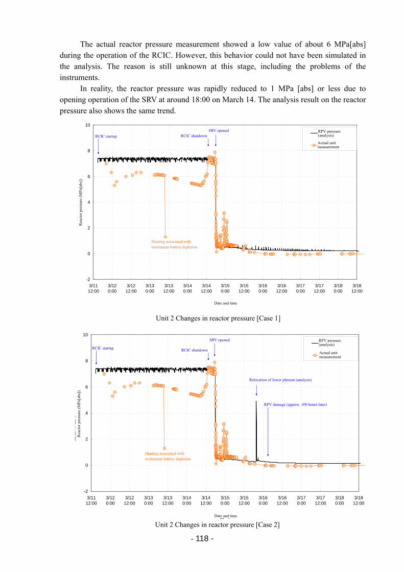
- 118 -
The actual reactor pressure measurement showed a low value of about 6 MPa[abs] during the operation of the RCIC. However, this behavior could not have been simulated in the analysis. The reason is still unknown at this stage, including the problems of the instruments.
In reality, the reactor pressure was rapidly reduced to 1 MPa [abs] or less due to opening operation of the SRV at around 18:00 on March 14. The analysis result on the reactor pressure also shows the same trend.
-2
0
2
4
6
8
10
3/1112:00
3/120:00
3/1212:00
3/130:00
3/1312:00
3/140:00
3/1412:00
3/150:00
3/1512:00
3/160:00
3/1612:00
3/170:00
3/1712:00
3/180:00
3/1812:00
日時
原子炉圧力
(M
Pa
[abs
])
RPV圧力(解析)
実機計測値
RCIC起動 RCIC停止SRV開
計装バッテリ枯渇に伴うハンチング
Unit 2 Changes in reactor pressure [Case 1]
RCIC startup RCIC shutdown SRV opened RPV pressure
(analysis)
Actual unitmeasurement
Hunting associated with instrument battery depletion
Date and time
Rea
ctor
pre
ssur
e (M
Pa[
abs]
)
-2
0
2
4
6
8
10
3/1112:00
3/120:00
3/1212:00
3/130:00
3/1312:00
3/140:00
3/1412:00
3/150:00
3/1512:00
3/160:00
3/1612:00
3/170:00
3/1712:00
3/180:00
3/1812:00
日時
原子炉圧力
(M
Pa[
abs]
)
RPV圧力(解析)
実機計測値
RCIC起動 RCIC停止
SRV開
計装バッテリ枯渇に伴うハンチング
下部プレナムへのリロケーション(解析)
RPV破損(約109時間後)
Unit 2 Changes in reactor pressure [Case 2]
Rea
ctor
pre
ssur
e (M
Pa[
abs]
)
Date and time
RCIC startup RCIC shutdown
SRV opened
Relocation of lower plenum (analysis)
RPV damage (approx. 109 hours later)
RPV pressure(analysis)
Actual unitmeasurement
Hunting associated with instrument battery depletion
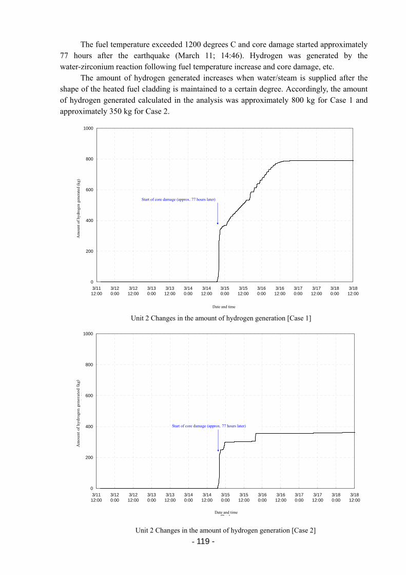
- 119 -
The fuel temperature exceeded 1200 degrees C and core damage started approximately 77 hours after the earthquake (March 11; 14:46). Hydrogen was generated by the water-zirconium reaction following fuel temperature increase and core damage, etc.
The amount of hydrogen generated increases when water/steam is supplied after the shape of the heated fuel cladding is maintained to a certain degree. Accordingly, the amount of hydrogen generated calculated in the analysis was approximately 800 kg for Case 1 and approximately 350 kg for Case 2.
0
200
400
600
800
1000
3/1112:00
3/120:00
3/1212:00
3/130:00
3/1312:00
3/140:00
3/1412:00
3/150:00
3/1512:00
3/160:00
3/1612:00
3/170:00
3/1712:00
3/180:00
3/1812:00
日時
水素発生量
(kg
)
炉心損傷開始(約77時間後)
Unit 2 Changes in the amount of hydrogen generation [Case 1]
Start of core damage (approx. 77 hours later)
Date and time
Am
ount
of
hydr
ogen
gen
erat
ed (
kg)
0
200
400
600
800
1000
3/1112:00
3/120:00
3/1212:00
3/130:00
3/1312:00
3/140:00
3/1412:00
3/150:00
3/1512:00
3/160:00
3/1612:00
3/170:00
3/1712:00
3/180:00
3/1812:00
日時
水素発生量
(kg
)
炉心損傷開始(約77時間後)
Unit 2 Changes in the amount of hydrogen generation [Case 2]
Start of core damage (approx. 77 hours later)
Date and time
Am
oun
t of
hyd
roge
n g
ener
ated
(kg
)
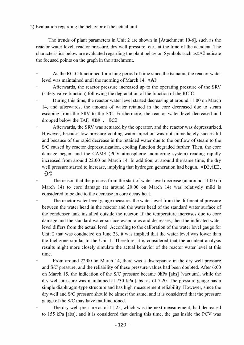
- 120 -
2) Evaluation regarding the behavior of the actual unit
The trends of plant parameters in Unit 2 are shown in [Attachment 10-6], such as the reactor water level, reactor pressure, dry well pressure, etc., at the time of the accident. The characteristics below are evaluated regarding the plant behavior. Symbols such as《A》indicate the focused points on the graph in the attachment.
・ As the RCIC functioned for a long period of time since the tsunami, the reactor water level was maintained until the morning of March 14.《A》
・ Afterwards, the reactor pressure increased up to the operating pressure of the SRV (safety valve function) following the degradation of the function of the RCIC.
・ During this time, the reactor water level started decreasing at around 11:00 on March 14, and afterwards, the amount of water retained in the core decreased due to steam escaping from the SRV to the S/C. Furthermore, the reactor water level decreased and dropped below the TAF.《B》, 《C》
・ Afterwards, the SRV was actuated by the operator, and the reactor was depressurized. However, because low-pressure cooling water injection was not immediately successful and because of the rapid decrease in the retained water due to the outflow of steam to the S/C caused by reactor depressurization, cooling function degraded further. Then, the core damage began, and the CAMS (PCV atmospheric monitoring system) reading rapidly increased from around 22:00 on March 14. In addition, at around the same time, the dry well pressure started to increase, implying that hydrogen generation had begun. 《D》,《E》,《F》
・ The reason that the process from the start of water level decrease (at around 11:00 on March 14) to core damage (at around 20:00 on March 14) was relatively mild is considered to be due to the decrease in core decay heat.
・ The reactor water level gauge measures the water level from the differential pressure between the water head in the reactor and the water head of the standard water surface of the condenser tank installed outside the reactor. If the temperature increases due to core damage and the standard water surface evaporates and decreases, then the indicated water level differs from the actual level. According to the calibration of the water level gauge for Unit 2 that was conducted on June 23, it was implied that the water level was lower than the fuel zone similar to the Unit 1. Therefore, it is considered that the accident analysis results might more closely simulate the actual behavior of the reactor water level at this time.
・ From around 22:00 on March 14, there was a discrepancy in the dry well pressure and S/C pressure, and the reliability of these pressure values had been doubted. After 6:00 on March 15, the indication of the S/C pressure became 0kPa [abs] (vacuum), while the dry well pressure was maintained at 730 kPa [abs] as of 7:20. The pressure gauge has a simple diaphragm-type structure and has high measurement reliability. However, since the dry well and S/C pressure should be almost the same, and it is considered that the pressure gauge of the S/C may have malfunctioned.
・ The dry well pressure as of 11:25, which was the next measurement, had decreased to 155 kPa [abs], and it is considered that during this time, the gas inside the PCV was
- 121 -
released into the atmosphere in some way, and the monitoring car reading near the main gate drastically increased.
3) Summary of the plant behavior
・ As the RCIC of Unit 2 functioned for a relatively long period of time, the core decay heat was lower than immediately after shutdown. However, as the high-pressure systems (RCIC) lost its function, a decrease in the reactor water level started. About 1 hour and 20 minutes after the RCIC shutdown, the fire engine’s pump was started up and preparations for low-pressure water injection were ready. However, the SRV did not immediately operate during reactor depressurization. It is considered that core damage occurred because the low-pressure water injection did not function immediately after the SRV was activated and the reactor depressurization was achieved, and because the cooling function degraded furthermore due to the rapid decrease in the retained water caused by the outflow of steam to the S/C associated with reactor depressurization.
・ According to the analysis by using the MAAP code, it is evaluated that core damage started due to the decrease in reactor water level followed by degradation of the function of the RCIC.
・ This pattern of event progression is similar for Unit 3, as described below. Note that from after 7:00 to around 11:00 on March 15, the gas inside the PCV was released, leading to an increase in the background level.
(3) Plant behavior of Fukushima Daiichi Unit 3
1) Evaluation of behavior by analysis
The event progression at Fukushima Daiichi Unit 3 is described in this section discussing the analysis results from the MAAP code and the measured data (actual values) for the reactor water level, reactor pressure, and the amount of hydrogen generated.
The analysis result shows that the water level was maintained by the automatic
operation of RCIC, shutdown at high reactor water level (L-8) and startup at low reactor water level (L-2) during the operation of the RCIC and HPCI.
There is a discrepancy between the actual measurement data and the analysis result in
terms of the operation of the RCIC and HPCI, and trend of the reactor pressure. However, the reactor water level was similarly maintained in both cases. Therefore, there are no differences from the viewpoint of analyzing the transition of the core condition.
The water level decreased in both cases, the analysis and the actual measured data,
following shutdown of the HPCI at 2:42 on March 13. According to the analysis, the reactor water level dropped to TAF approximately 40 hours after the earthquake (March 11; 14:46) and dropped to BAF approximately 42 hours after the earthquake.
- 122 -
As the reliability of the water level instrumentation could not be confirmed for freshwater injection that was started at 9:25 on March 13 and subsequent seawater injection, analyses were conducted for the following two cases:
[Case 1] The case that the amount of water injected into the reactor is adjusted to be less than the discharge flow meter reading of fire engines, so that the analyzed reactor water level would be equivalent to the actually measured value, based on the fact that the measured value of the reactor water level was the level that would immerse about half of the fuel in water.
[Case 2] The case that the amount of water injected into the reactor is adjusted to be less than the discharge flow meter reading of fire engines, so that the fuel would be completely exposed, based on the assumption that the actual reactor water level was lower than its measured value, that was the level that would immerse about half of the fuel in water.
In Case 2, where more fuel is exposed, the RPV would be damaged at around 8:00 on March 14.
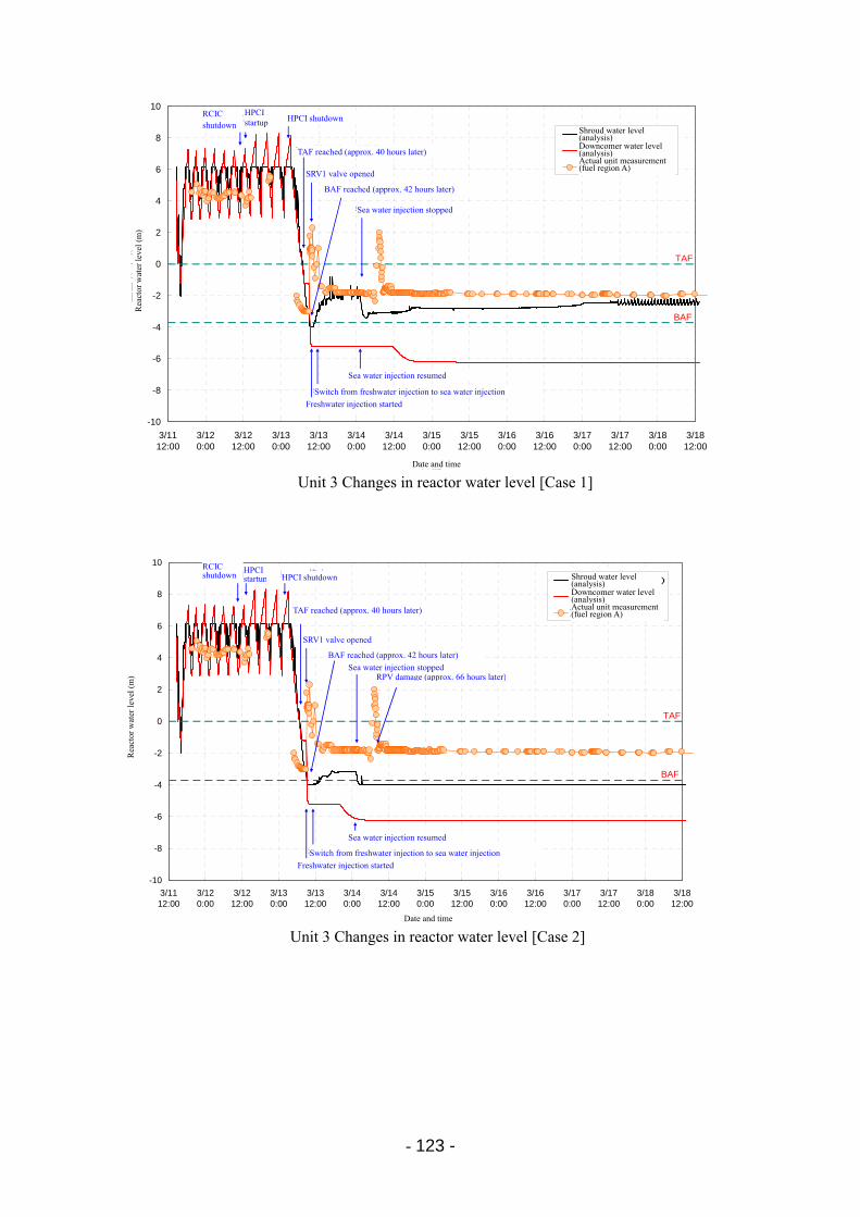
- 123 -
-10
-8
-6
-4
-2
0
2
4
6
8
10
3/1112:00
3/120:00
3/1212:00
3/130:00
3/1312:00
3/140:00
3/1412:00
3/150:00
3/1512:00
3/160:00
3/1612:00
3/170:00
3/1712:00
3/180:00
3/1812:00
日時
原子炉水位
(m
)シュラウド内水位(解析)
ダウンカマ水位(解析)
実機計測値
TAF
BAF
RCIC停止
SRV1弁開
淡水注入より海水注水に切替
海水注水停止
海水注水再開
HPCI停止
淡水注入開始
HPCI起動
TAF到達(約40時間後)
BAF到達(約42時間後)
Unit 3 Changes in reactor water level [Case 1]
Shroud water level (analysis) Downcomer water level (analysis) Actual unit measurement (fuel region A)
Date and time
RCIC shutdown
HPCI startup HPCI shutdown
TAF reached (approx. 40 hours later)
SRV1 valve opened
BAF reached (approx. 42 hours later)
Sea water injection stopped
Sea water injection resumed
Switch from freshwater injection to sea water injection
Freshwater injection started
Rea
ctor
wat
er le
vel (
m)
-10
-8
-6
-4
-2
0
2
4
6
8
10
3/1112:00
3/120:00
3/1212:00
3/130:00
3/1312:00
3/140:00
3/1412:00
3/150:00
3/1512:00
3/160:00
3/1612:00
3/170:00
3/1712:00
3/180:00
3/1812:00
日時
原子炉水位
(m
)
シュラウド内水位(解析)
ダウンカマ水位(解析)
実機計測値
TAF
BAF
RCIC停止
SRV1弁開
淡水注入より海水注水に切替
海水注水停止
海水注水再開
HPCI停止
淡水注入開始
HPCI起動
TAF到達(約40時間後)
BAF到達(約42時間後)
RPV破損(約66時間後)RPV damage (approx. 66 hours later)
Unit 3 Changes in reactor water level [Case 2]
Shroud water level (analysis) Downcomer water level (analysis) Actual unit measurement (fuel region A)
Date and time
RCIC shutdown
HPCI startup HPCI shutdown
TAF reached (approx. 40 hours later)
SRV1 valve opened
BAF reached (approx. 42 hours later)
Sea water injection stopped
Sea water injection resumed
Switch from freshwater injection to sea water injection
Freshwater injection started
Rea
ctor
wat
er le
vel (
m)
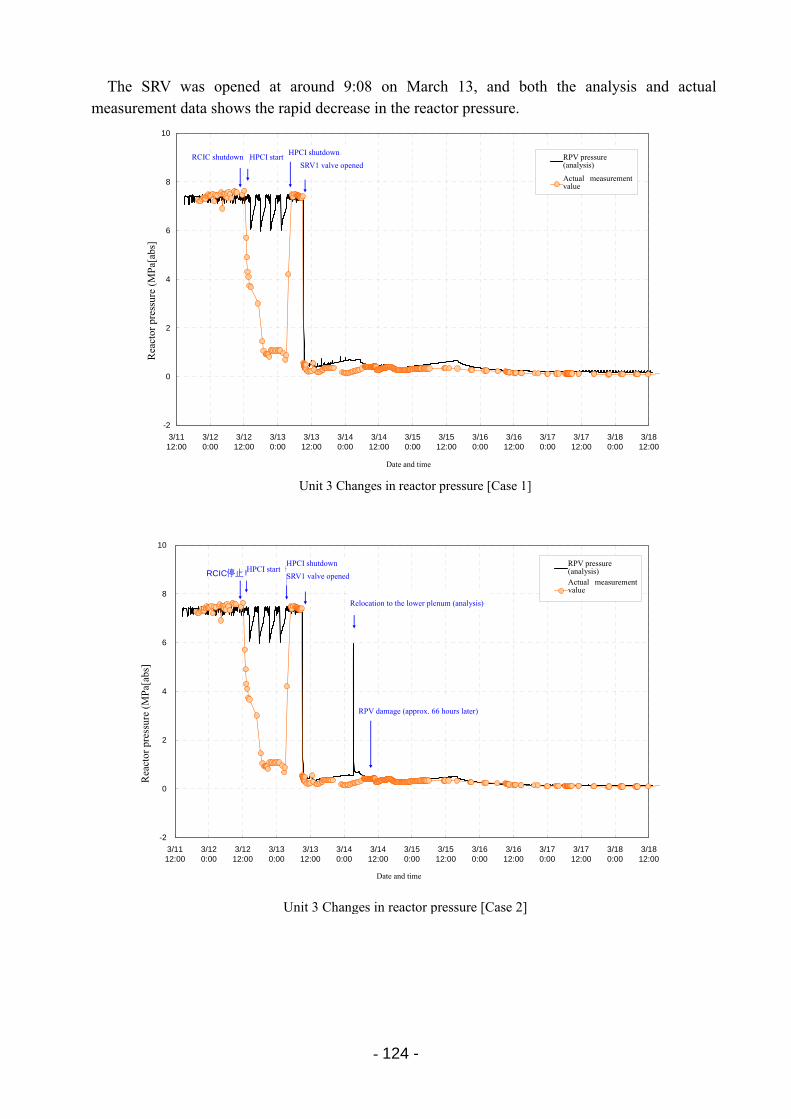
- 124 -
The SRV was opened at around 9:08 on March 13, and both the analysis and actual measurement data shows the rapid decrease in the reactor pressure.
-2
0
2
4
6
8
10
3/1112:00
3/120:00
3/1212:00
3/130:00
3/1312:00
3/140:00
3/1412:00
3/150:00
3/1512:00
3/160:00
3/1612:00
3/170:00
3/1712:00
3/180:00
3/1812:00
日時
原子炉圧力
(M
Pa[
abs]
)RPV圧力(解析)
実機計測値
HPCI停止RCIC停止SRV1弁開
HPCI起動 RPV pressure (analysis)
Rea
ctor
pre
ssur
e (M
Pa[
abs]
RCIC shutdown HPCI start
HPCI shutdown
SRV1 valve opened
Actual measurement value
Date and time
Unit 3 Changes in reactor pressure [Case 1]
-2
0
2
4
6
8
10
3/1112:00
3/120:00
3/1212:00
3/130:00
3/1312:00
3/140:00
3/1412:00
3/150:00
3/1512:00
3/160:00
3/1612:00
3/170:00
3/1712:00
3/180:00
3/1812:00
日時
原子炉圧力
(M
Pa
[ab
s])
RPV圧力(解析)
実機計測値
HPCI停止RCIC停止SRV1弁開
HPCI起動
下部プレナムへのリロケーション(解析)
RPV破損(約66時間後)
Date and time
Rea
ctor
pre
ssur
e (M
Pa[
abs]
RPV pressure (analysis) HPCI start
HPCI shutdown
SRV1 valve openedActual measurement value
Relocation to the lower plenum (analysis)
RPV damage (approx. 66 hours later)
Unit 3 Changes in reactor pressure [Case 2]
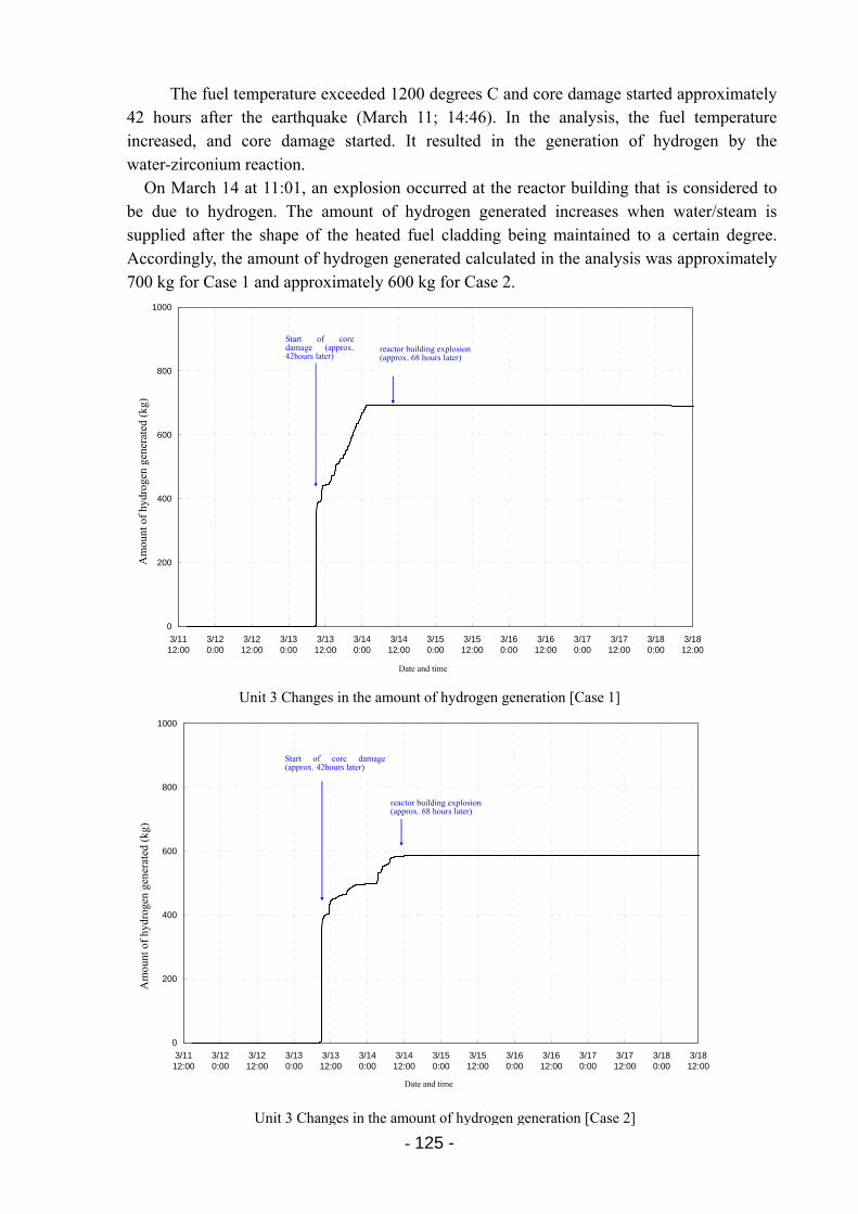
- 125 -
The fuel temperature exceeded 1200 degrees C and core damage started approximately 42 hours after the earthquake (March 11; 14:46). In the analysis, the fuel temperature increased, and core damage started. It resulted in the generation of hydrogen by the water-zirconium reaction.
On March 14 at 11:01, an explosion occurred at the reactor building that is considered to be due to hydrogen. The amount of hydrogen generated increases when water/steam is supplied after the shape of the heated fuel cladding being maintained to a certain degree. Accordingly, the amount of hydrogen generated calculated in the analysis was approximately 700 kg for Case 1 and approximately 600 kg for Case 2.
0
200
400
600
800
1000
3/1112:00
3/120:00
3/1212:00
3/130:00
3/1312:00
3/140:00
3/1412:00
3/150:00
3/1512:00
3/160:00
3/1612:00
3/170:00
3/1712:00
3/180:00
3/1812:00
日時
水素発生量
(kg
)
炉心損傷開始(約42時間後)
原子炉建屋爆発(約68時間後)
Date and time
Am
ount
of
hydr
ogen
gen
erat
ed (
kg)
Start of coredamage (approx. 42hours later) reactor building explosion
(approx. 68 hours later)
Unit 3 Changes in the amount of hydrogen generation [Case 1]
0
200
400
600
800
1000
3/1112:00
3/120:00
3/1212:00
3/130:00
3/1312:00
3/140:00
3/1412:00
3/150:00
3/1512:00
3/160:00
3/1612:00
3/170:00
3/1712:00
3/180:00
3/1812:00
日時
水素発生量
(kg
)
原子炉建屋爆発(約68時間後)
炉心損傷開始(約42時間後)
Am
ount
of
hydr
ogen
gen
erat
ed (
kg)
Start of core damage(approx. 42hours later)
Date and time
reactor building explosion (approx. 68 hours later)
Unit 3 Changes in the amount of hydrogen generation [Case 2]
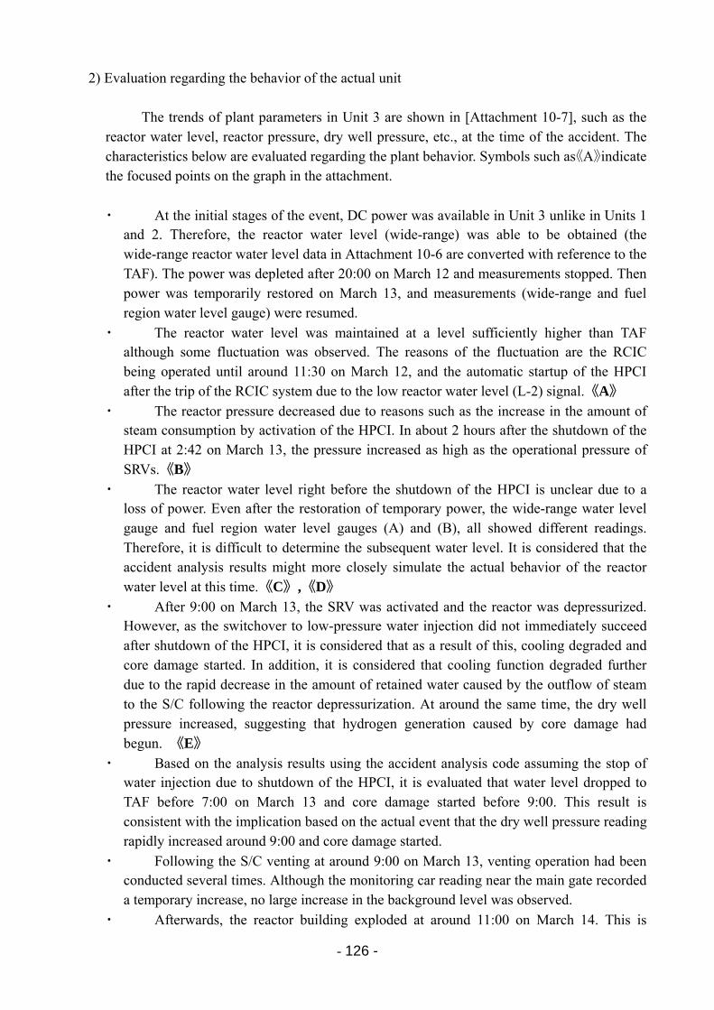
- 126 -
2) Evaluation regarding the behavior of the actual unit
The trends of plant parameters in Unit 3 are shown in [Attachment 10-7], such as the reactor water level, reactor pressure, dry well pressure, etc., at the time of the accident. The characteristics below are evaluated regarding the plant behavior. Symbols such as《A》indicate the focused points on the graph in the attachment.
・ At the initial stages of the event, DC power was available in Unit 3 unlike in Units 1 and 2. Therefore, the reactor water level (wide-range) was able to be obtained (the wide-range reactor water level data in Attachment 10-6 are converted with reference to the TAF). The power was depleted after 20:00 on March 12 and measurements stopped. Then power was temporarily restored on March 13, and measurements (wide-range and fuel region water level gauge) were resumed.
・ The reactor water level was maintained at a level sufficiently higher than TAF although some fluctuation was observed. The reasons of the fluctuation are the RCIC being operated until around 11:30 on March 12, and the automatic startup of the HPCI after the trip of the RCIC system due to the low reactor water level (L-2) signal.《A》
・ The reactor pressure decreased due to reasons such as the increase in the amount of steam consumption by activation of the HPCI. In about 2 hours after the shutdown of the HPCI at 2:42 on March 13, the pressure increased as high as the operational pressure of SRVs.《B》
・ The reactor water level right before the shutdown of the HPCI is unclear due to a loss of power. Even after the restoration of temporary power, the wide-range water level gauge and fuel region water level gauges (A) and (B), all showed different readings. Therefore, it is difficult to determine the subsequent water level. It is considered that the accident analysis results might more closely simulate the actual behavior of the reactor water level at this time.《C》,《D》
・ After 9:00 on March 13, the SRV was activated and the reactor was depressurized. However, as the switchover to low-pressure water injection did not immediately succeed after shutdown of the HPCI, it is considered that as a result of this, cooling degraded and core damage started. In addition, it is considered that cooling function degraded further due to the rapid decrease in the amount of retained water caused by the outflow of steam to the S/C following the reactor depressurization. At around the same time, the dry well pressure increased, suggesting that hydrogen generation caused by core damage had begun. 《E》
・ Based on the analysis results using the accident analysis code assuming the stop of water injection due to shutdown of the HPCI, it is evaluated that water level dropped to TAF before 7:00 on March 13 and core damage started before 9:00. This result is consistent with the implication based on the actual event that the dry well pressure reading rapidly increased around 9:00 and core damage started.
・ Following the S/C venting at around 9:00 on March 13, venting operation had been conducted several times. Although the monitoring car reading near the main gate recorded a temporary increase, no large increase in the background level was observed.
・ Afterwards, the reactor building exploded at around 11:00 on March 14. This is
- 127 -
presumed to have occurred due to the accumulation of hydrogen in the reactor building generated as a result of core damage and the hydrogen being ignited by some source.
3) Summary of the plant behavior
・ In Unit 3, the preparations for low-pressure water injection were performed by activating the diesel-driven fire pump. However, because the reactor pressure was higher than the water injection pressure, switching to low-pressure water injection was not immediately successful after shutdown of the high-pressure systems (HPCI). This caused degradation of cooling and thus leading to core damage.
・ S/C venting was conducted and repeated several times. The monitoring car reading near the main gate increased temporarily. However, no large increase in the background level was observed.
・ In addition, the hydrogen that was generated in association with the core damage was not completely retained in the PCV and leaked into the reactor building, and is considered to have caused the explosion of the reactor building.
(4) Plant behavior of Fukushima Daini Unit 1
1) Evaluation regarding the behavior of the actual unit
The trends of plant parameters in Fukushima Daini Unit 1 are shown in [Attachment 10-8], such as the reactor water level, reactor pressure, dry well pressure, etc., at the time of the accident. The characteristics below are evaluated regarding the plant behavior. Symbols such as《A》indicate the focused points on the graph in the attachment. ・ The reactor water level was maintained since the tsunami by the RCIC.《A》
・ In parallel to this, the reactor pressure was gradually decreased using the SRV, and at the same time, the MUWC, which is a low-pressure water injection system, was started up and put on standby.《B》
・ By gradually reducing the reactor pressure using the SRV, the MUWC was able to begin water injection. The MUWC was used to maintain the reactor water level, and the RCIC was stopped.《C》
・ As a result, the reactor water level was maintained at a level close to the normal water level, and a seamless switchover could be performed to low-pressure water injection.《A》
・ The dry well pressure gradually increased due to loss of heat removal using the emergency seawater system, and reached the design pressure of the dry well on the third day.《D》
・ As the emergency seawater system was restored on the third day, the dry well pressure started to decrease.《E》
・ As a backup measure for the delay in the restoration of the emergency seawater system, preparatory work had been finished for the PCV venting, which could decrease in the PCV pressure.
- 128 -
2) Summary of the plant behavior
・ Fukushima Daini Unit 1 successfully maintained the integrity of the core and achieved cold shutdown. In this unit, operation of the low-pressure water injection (MUWC) was started while high-pressure water injection (RCIC) was functioning.
・ Then, while the water level was maintained using the high-pressure water injection, the reactor pressure was decreased through gradual depressurization down to a pressure that enabled water injection using the low-pressure water injection system, and water injection from the low-pressure injection system was started. During this time, the water injection function was seamlessly switched over while maintaining the reactor water level.
・ Afterwards, the ultimate heat sink was reestablished through restoration of power to the RHR seawater system leading to cold shutdown.
・ Cold shutdown was basically achieved in the same way for Fukushima Daini Units 2 and 4. In Fukushima Daini Unit 3, one emergency seawater system was available. Therefore, cold shutdown was achieved according to the normal procedures.
・ As mentioned above, the AM measures that had been developed so far were able to function effectively at the Fukushima Daini NPS, and the plant was successfully stabilized and achieved cold shutdown.
(5) Issues based on plant behavior
Since the following characteristics are clear based on the overall progression of events, it is considered to be important to work on these issues in order to ensure that core cooling and damage prevention are successful.
1) If the cooling and water injection functions of the high-pressure systems are lost at an
early stage after reactor shutdown, the reactor water level decreases rapidly. If the cooling and water injection functions are lost in a few hours after reactor shutdown, water level will drop to TAF in about 2 hours following loss of the functions. Event progression is very quick once the cooling and water injection of the high-pressure systems are lost.
It is necessary for high-pressure water injection systems to be initiated immediately after an accident. It is important to utilize originally installed equipment to cope with this. → Promptly initiate flooding methods using high-pressure water injection systems
2) Dry well pressure increases gradually while the high-pressure systems are in operation.
However, once core damage begins, the dry well pressure increases rapidly due to the generation of hydrogen. In Unit 2, the time that core damage started can be identified through the measured data of the containment atmosphere monitoring system. The measured data is consistent with the start of the rapid increase in dry well pressure. It was also observed that the dry well pressure started to increase rapidly after the depressurization of the reactor. It is considered that core cooling further degraded due to the rapid decrease in the
- 129 -
amount of water retained in the reactor caused by the flashing, leading to core damage. Therefore, it is important to prepare reliable low-pressure systems before reactor
depressurization and to smoothly switch over to the low-pressure systems while maintaining a balance between the decrease in water level due to depressurization and the amount of water injection. At this stage, it is also important to ensure operability of depressurization by using SRVs. → Initiate depressurization methods before losing the function of high-pressure water
injection → Stable low-pressure water injection methods should be available during the
depressurization stage
3) As mentioned earlier, at Fukushima Daini Unit 1, operation of low-pressure water injection (MUWC) was initiated while high-pressure system water injection (RCIC) was functioning. Depressurization was gradually conducted while maintaining the water level through water injection using the high-pressure systems. After the reactor pressure decreased low enough to be able to inject water through the low-pressure systems, the water injection functions were seamlessly switched over. In addition, the heat removal function using the emergency seawater system was recovered while the low-pressure water injection system was maintaining its function.
At Fukushima Daini Unit 1, preparations had been made to remove heat from the PCV
through low-pressure water injection and venting (feed and bleed) in case where the dry well pressure became higher, although this was not implemented in the end. It is important that such response can be realized even under adverse conditions. → Provide reliable PCV venting methods (heat removal through the atmospheric
discharge of heat) → Provide measures to restore cooling function using seawater
4) In order to accurately implement the above operations, it is important to have an
accurate understanding of the plant status. In the case of Fukushima Daiichi Unit 1, the function of monitoring instruments was lost during the serious event progress. Monitoring of the reactor water level was also not possible in Fukushima Daiichi Unit 3 due to the depletion of DC power for a few hours before shutdown of the HPCI. Monitoring functions are also important for switching the water injection systems, in addition to the understanding of the plant status.
Therefore, it is important to maintain monitoring function for parameters such as reactor water level.
→ Provide measures in order to ensure measurements required for the
above-mentioned operations and monitoring of the conditions
- 130 -
10.2 Issues on facilities and functions (1) Conditions of functional loss [Appendix 10-9, 10]
Based on the accident progression described in the previous section, equipment and functional issues are identified for each of the following steps:
1) Maintaining cooling function after the earthquake; 2) Maintaining high-pressure water injection (cooling); 3) Switching to low-pressure water injection systems through reactor depressurization; 4) Removal of decay heat using the emergency seawater system; 5) Heat removal from the PCV by venting; 6) Prevention of hydrogen explosion; and 7) Maintaining monitoring functions.
1) Maintaining cooling function after the earthquake
In the case of Fukushima Daiichi NPS, off-site power was lost after the earthquake.
However, the power supply was maintained for all units by EDGs. At the Fukushima Daini NPS, off-site power was available for all units. Therefore, AC power was available for both Fukushima Daiichi and Fukushima Daini NPSs after the earthquake, and the core cooling function was maintained.
At this stage, there were no factors leading to core damage. 2) Maintaining high-pressure water injection (cooling) after the tsunami
Fukushima Daiichi Unit 1 lost its IC function immediately after the tsunami. Core
damage is considered to have occurred in a short period of time. Since the IC does not need active components during its operation, the reliability of the equipment is high with a low probability of mechanical failure. However, it could not be fully functioned due to the loss of DC power. The loss of DC power also caused the HPCI start up failure as back-up high-pressure cooling water injection system. The DC power lost its function due to the water damage to the power panels caused by the tsunami flooding.
At Fukushima Daiichi Unit 2, high-pressure water injection was able to be maintained due to the continuous operation of the RCIC, which was started up before the tsunami attack. However, when the DC power was lost, no backup system could be provided for the high-pressure water injection systems. The DC power lost its function due to the water damage to the power panels caused by the tsunami flooding.
At Fukushima Daiichi Unit 3, the RCIC functioned and high-pressure cooling water injection was maintained. When the decrease in water level as a result of loss of function of the RCIC, the back-up HPCI was started up due to the DC power supply and water injection was continued. However, after the HPCI shutdown, DC power was depleted, and it became
- 131 -
impossible to restart the RCIC and HPCI. The depletion of DC power was due to the loss of AC power to the battery charger to recharge the battery, and AC power was lost due to the water damage to the power panel.
As mentioned above, it is important to maintain AC power in order to have the function of high-pressure water injection (cooling) such as the IC, RCIC, and HPCI.
As for the case where IC lost DC power and was isolated due to the tsunami at the Fukushima Daiichi Unit 1, since it resulted in the loss of cooling function, it is necessary to clarify and examine the issues and carefully pursue the possibility of more flexible operation.
3) Switching to low-pressure water injection systems through reactor depressurization
At Fukushima Daiichi Unit 2, it was necessary to depressurize the reactor and switch to
a low-pressure water injection method when the high-pressure water injection methods were lost. However, originally installed low-pressure water injection equipment could not be operated due to the loss of AC power. In addition, large equipment that utilized the emergency seawater system for cooling could not be utilized easily. Furthermore, stand-alone small-scale equipment such as condensate make-up pumps could also not be used due to the loss of AC power and water damage of this equipment. The AC power lost its function due to the water damage to the power panels caused by the tsunami flooding.
In addition, the depressurization using the SRV was delayed, and it was difficult to
depressurize the reactor in a timely manner. This was made difficult by the inability to operate the control solenoid valve due to the loss of DC power. This pattern of event progression is similar for Fukushima Daiichi Unit 3.
Diesel-driven fire pumps are low-pressure water injection equipment that do not use electric power. Although these pumps were started up in Units 1 and 2, they lost their function in a short period of time due to tsunami flooding. The function of the pump was maintained in Unit 3. However, difficulty in reactor depressurization prevented water injection by using the equipment.
As a result, alternative measures, such as the use of temporary batteries and fire engines, had to be utilized
In order to ensure the function of the SRV, it is important to maintain DC power. In addition, it is also important to maintain highly-reliable low-pressure water injection equipment available.
4) Removal of decay heat using the emergency seawater system
The heat removal function of the emergency seawater system was lost due to due to
water damage to the pump motor by the tsunami and loss of AC power. The AC power lost its function due to the water damage to the power panels caused by the tsunami flooding.
In Fukushima Daiichi Units 1 to 3, the accident progressed and led to core damage quicker than the restoration of the emergency seawater system. In Fukushima Daiichi Units 5
- 132 -
and 6 and Fukushima Daini Units 1 to 4, low-pressure water injection was successfully implemented. In these plants, recovery work was implemented, such as motor restoration for the emergency seawater system, temporary restoration using temporary pumps, and power restoration using temporary power sources. It is considered that success in low-pressure water injection and core cooling provided additional time to restore the emergency seawater system.
As mentioned above, it is important to provide enough time for emergency response by maintaining low-pressure water injection. It is also important to enhance reliability for the response by preparing temporary restoration measures for the seawater system in advance.
5) Heat removal from the PCV by venting
In Fukushima Daiichi Units 1 to 3, which led to core damage, venting was inevitable
due to the increase in pressure in the PCV. For PCV venting, it was necessary to open two valves: one MO valve and the other AO valve. The MO valve could not be opened from the MCR due to the loss of AC power. AC power was lost because of the functional loss of the power panel due to tsunami water damage. In addition, the AO valve could not be opened from the MCR because of the decrease in the driving air pressure and the loss of AC power supply to the solenoid valve for driving the air flow. The drive air pressure decreased due to the loss of function of the originally installed air compressor following the loss of AC power. AC power was lost because of the functional loss of the power panel due to tsunami water damage. For operation of the air compressor, it is necessary to cool the equipment, and therefore, the cooling function of the seawater system is also necessary.
As mentioned above, in order to provide a venting path, it is important to maintain AC power. It is also important to prepare valve operation methods in advance by alternative means such as providing drive air pressure. The PCV venting has the primary function of removing heat from the PCV. Therefore, after low-pressure water injection methods became available to prevent core damage, it is important to utilize it as a heat removal source until the heat removal function of the emergency seawater system is recovered.
It is considered that PCV venting can be ensured by implementing the above measures. In order to provide low-pressure water injection functions and heat removal functions in a more certain manner, it is also necessary to review measures to actively operate the rupture disk. However, since it might cause inadvertent discharge, this issue should be carefully investigated.
6) Prevention of hydrogen explosion
In the plants that led to core damage, a substantial amount of hydrogen was generated
by the zirconium-water reaction in the reactor and accumulated inside the PCV. The hydrogen is considered to have somehow leaked into the reactor building, causing the explosion in the building. The PCV was filled with nitrogen, which is an inert gas. Since an
- 133 -
explosion did not occur in the PCV, it is considered that the nitrogen injection into the PCV functioned properly. The SGTS, which ventilates the building via filters to remove radioactive materials, lost its function due to the loss of AC power. Therefore, the hydrogen accumulated in the reactor building could not be actively exhausted. The AC power lost its function due to the water damage to the power panels caused by the tsunami flooding.
For Fukushima Daiichi Units 1 and 3, the reactor buildings were damaged due to the hydrogen explosions. On the other hand, an explosion did not occur in the building at the Fukushima Daiichi Unit 2. This is considered to be because the blowout panel on the top floor of the reactor building was opened due to the Unit 1 explosion, thereby providing ventilation of the Unit 2 reactor building.
At Fukushima Daiichi Unit 4, it is unlikely that hydrogen was generated in that plant. It is considered that the explosion was induced by the accumulation of hydrogen that flowed into the building through SGTS ducts during venting operation of the neighboring Unit 3.
For preventing hydrogen explosions, it is necessary to further investigate the leakage path to the reactor buildings. The experience in Fukushima Daiichi Unit 2 shows that ventilation would be effective in preventing explosions. Note that the first priority is on preventing hydrogen generation itself by preventing core damage.
7) Maintaining monitoring functions
During the accident, monitoring functions were lost that were required to understand
the status of the core at the time of the accident, such as the reactor water level and reactor pressure. The monitoring functions were lost due to the loss of DC power and AC power systems. The power systems lost their functions due to the water damage to the power panels caused by the tsunami flooding.
Therefore, it is important to provide power to instruments in order to maintain function
of instruments used for monitoring vital parameters in the accident.
To improve safety, for instance, taking into consideration the fact that the reading of the reactor water level gauges greatly differed from the actual value after core damage, it is necessary to have enough diversity rather than simply enhancing the accuracy of the water level gauge. To do this, it is considered that further R&D for measurement devices that meet demands for the accident management is important for further enhancement of the safety.
(2) Summary of equipment and functional issues
The correlation of factors leading to the loss of important functions based on the progression of this accident is described below. The accident was caused by the simultaneous loss of multiple safety functions due to the tsunami flooding. The main factors of the accident are “the simultaneous loss of total AC power and DC power for an extended period of time” and “the loss of the heat removal function of the emergency seawater system for an extended period
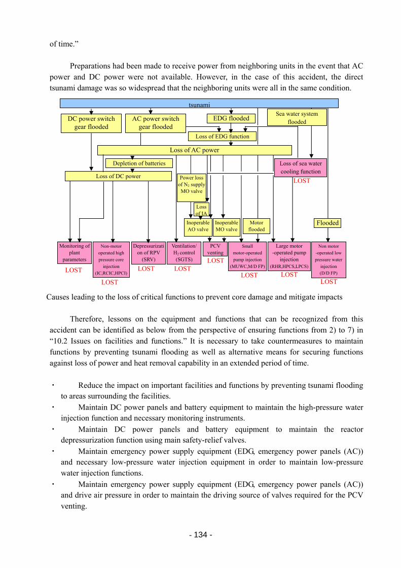
- 134 -
of time.”
Preparations had been made to receive power from neighboring units in the event that AC power and DC power were not available. However, in the case of this accident, the direct tsunami damage was so widespread that the neighboring units were all in the same condition.
Causes leading to the loss of critical functions to prevent core damage and mitigate impacts
Therefore, lessons on the equipment and functions that can be recognized from this accident can be identified as below from the perspective of ensuring functions from 2) to 7) in “10.2 Issues on facilities and functions.” It is necessary to take countermeasures to maintain functions by preventing tsunami flooding as well as alternative means for securing functions against loss of power and heat removal capability in an extended period of time.
・ Reduce the impact on important facilities and functions by preventing tsunami flooding to areas surrounding the facilities.
・ Maintain DC power panels and battery equipment to maintain the high-pressure water injection function and necessary monitoring instruments.
・ Maintain DC power panels and battery equipment to maintain the reactor depressurization function using main safety-relief valves.
・ Maintain emergency power supply equipment (EDG, emergency power panels (AC)) and necessary low-pressure water injection equipment in order to maintain low-pressure water injection functions.
・ Maintain emergency power supply equipment (EDG, emergency power panels (AC)) and drive air pressure in order to maintain the driving source of valves required for the PCV venting.
DC power switch gear flooded
EDG flooded
Loss of EDG function
Depletion of batteries
Loss of DC power LOST
LOST LOST LOST
LOSTLOST LOST
LOST
LOST
Loss of IA
Inoperable AO valve
Inoperable MO valve
Monitoring of plant
parameters
Non-motor
operated high
pressure core
injection
(IC,RCIC,HPCI)
Depressurization of RPV
(SRV)
Ventilation/H2 control (SGTS)
Small
motor-operated
pump injection
(MUWC,M/D FP)
PCV venting
Large motor -operated pump
injection (RHR,HPCS,LPCS)
Non motor
-operated low
pressure water
injection
(D/D FP)
Loss of AC power
Power loss of N2 supply
MO valve
tsunamiSea water system
flooded AC power switch gear flooded
Flooded
Loss of sea water cooling function
Motor flooded
- 135 -
・ Maintain emergency power supply equipment (EDG, emergency power panels (AC)) and emergency seawater system cooling equipment in order to maintain decay heat removal and auxiliary unit cooling.
・ Maintain emergency power supply equipment (EDG, emergency power panels (AC)) in order to maintain the functions of the SGTS.
・ Provide alternative measures for functions to prevent core damage even when “DC power,” “AC power,” and “Emergency seawater system’s heat removal function” are lost.
10.3 Issues based on factors impacting worker’s performance on the accident response
The tsunami flooded the entire building area of the Fukushima Daiichi NPS. This resulted in a loss of almost all the functions required for accident response, such as lighting, plant monitoring equipment, communication measures, and reactor cooling equipment, etc.
Such circumstances were greatly beyond the preexisting framework (premises for response systems and procedure manuals, etc.), and made the site response (operations) extremely difficult. In addition, the workers were forced to face an extremely difficult situation where the plant status at multiple units simultaneously worsened minute by minute, which created more and more work obstacles.
Amidst these circumstances, the power station, utilizing its accumulated knowledge and experience, came up with response actions for water injection to the reactors and PCV venting, etc, in order to stabilize the plants, and implemented these measures under an extremely poor environment in the field. The issues faced by the power station (increasing work obstacles, etc.) relating to water injection to the reactors and PCV venting, which are important response operations, are described below.
(1) Loss of reactor cooling and water injection functions
Due to the loss of the power and sea water (cooling) systems as the result of the tsunami,
the function of almost all equipment that was able to be used for reactor cooling and water injection was lost. This included the usual condensate and feed water system to alternative water injection systems, such as the ECCS and make up water condensate, etc.
In the initial stages of the accident (a few hours to a few days after the accident), the IC (Unit 1), RCIC (Unit 2), RCIC, and HPCI (Unit 3) were started up. However, subsequently, alternative water injection using fire engines became the only practical means of water injection Note 1).
In order to inject water into the reactors from fire engines, it was necessary to reduce reactor pressure to around 1MPa or less, however the SRVs used for depressurization were not able to be opened due to the loss of power (DC). Since no procedure was available regarding water injection using fire engines, procurement and connection of batteries, compressors and nitrogen gas cylinders to open the SRVs and depressurize the reactor, workers had to act flexibly.
Note 1) Water injection using temporary electric pumps was implemented starting on March 27
(Unit 2), March 28 (Unit 3), and March 29 (Unit 1).
- 136 -
(2) Loss of PCV heat removal function (venting not possible)
In order to configure the lines for PCV venting, it was necessary to operate the motor operated valve and air operated valve. However, due to the loss of power and the loss of compressed air to drive the air operated valve, none of these valves could be opened, and vent line configuration was not possible through normal means. Therefore, the motor operated valve was opened manually in the field.
The air operated valve was opened by the power station employees connecting temporary AC generators, air compressors and gas cylinders.
(3) Flexible response
As shown above, workers faced a situation in which response was not provided in the
procedures that had been developed in advance. Therefore, they had to come up with flexible response measures in order to implement necessary plant operations, such as reactor water injection and PCV venting.
(4) Loss of plant monitoring functions (including radiation monitoring and meteorological
observation) (loss of monitoring functions) Plant monitoring:
In the MCR, multiple monitoring instruments had been provided for each parameter, such as the reactor water level. Since almost all power, including DC power, was lost due to the tsunami, these instruments could not be used to monitor the plant. It also was difficult to understand the equipment status in the MCR, since equipment status displays such as the valve status, etc, were also lost.
For some instruments, such as the reactor water level, reactor pressure, and PCV pressure, batteries were connected to enable readings to be checked. However, it took time to read the instruments, and the obtained information was limited in terms of both type and frequency. Furthermore, some devices were exposed to conditions that greatly exceeded their usual usage environmental conditions. Therefore, there were cases in which it was difficult to understand plant status based on independent instrument readings (such as the reactor water level gauge)
Radiation monitoring:
Due to the loss of power after the tsunami, radiation monitoring equipment, such as the main stack monitor, area monitors inside the plant buildings, and monitoring posts installed near the site boundary of the power station became unavailable. As a result, radiation measurement cars and portable radiation counters were used to obtain dose measurements.
Since the function of the main stack radiation monitor was lost, timely and sensitive information regarding successful PCV venting (opening of the rupture disc) could not be obtained.
- 137 -
Meteorological equipment: There is an online system that measures and displays wind direction, wind speed, etc.
However, this was unavailable due to the loss of power after the tsunami. As a result, it was necessary to use alternative means (for instance, using Fukushima
Daini NPS data) to determine wind direction, wind speed etc., when predicting and evaluating radiation doses rate during PCV venting.
(5) Communication equipment (loss of communication methods)
Both the wireless phone system and wired paging equipment (in-plant fixed communication device and public-address system), which are generally used for on-site communication, were able to be used immediately after the earthquake. However, this equipment became unusable due to the power loss following the tsunami. Therefore, communication within the site (between the MCR and the field) and between the seismic isolated building (ERC)) and the field became difficult.
Apart from some cases in which the radios on fire engines, etc., were avalable, information in the field could not be obtained until a workers who went to the filed returned to report the conditions.
Furthermore, the safety parameter display system (SPDS), which communicates plant
status in the event of an accident, did not function since there were no parameters transmitted due to the plant-side power loss. The only communication methods that were able to be used between the MCR and the seismic isolated building were the hotline and landline. As a result, not only was the information that could be obtained from the site (plant information, operation status) extremely limited, but it also took time to obtain this limited information.
(6) Deterioration of the work environment (tsunami debris, loss of lighting, release of radioactive
materials, explosion damage)
In addition to aftershocks, tsunami risks, and tsunami debris interfering with outdoor work, the loss of lighting in the MCR, station buildings, and the field due to the total loss of AC power made work even more difficult. In addition, the release of radioactive materials degraded the work environment in the MCR and inside and outside the buildings rapidly.
In addition, response work was conducted under extremely difficult conditions; people were injured by the building explosions. The explosion caused setbacks such as damage to the temporary water hoses, and cables, etc.
10.4 Summary of the analysis and the identification of issues
The causes leading to core damage in Units 1 to 3 of Fukushima Daiichi can roughly be summarized as follows, although there are some differences among the units:
・ When designing NPSs, multiple, diverse, and independent emergency system cooling
- 138 -
equipment, etc., were installed in preparation for accidents caused by a single equipment failure.
Meanwhile, for tsunamis, the latest knowledge had been reflected in the designs. However, it was thought that there were enough margins in terms of the height of the building premises, and therefore, the possibility of a tsunami running up to the elevation of the building and causing multiple failures of equipment had not been taken into account.
・ Under such conditions, a huge earthquake occurred with a magnitude of 9.0, the 4th largest in the world ever to be recorded, followed by a tsunami with a height reaching 13m. This tsunami ran up to the elevation of the buildings of the Fukushima Daiichi NPS, severely damaged the facilities such as air intakes and carry-in entrances of the buildings, and flowed into the buildings where equipment was installed.
This caused indoor equipment as well as outdoor equipment, especially the EDGs and power-related equipment, to lose their functions. Furthermore, the units except for Unit 3 lost DC power that was necessary for the operations such as control and measurement.
・ In this way, the loss of power in Units 1-3 caused all motor-driven equipment to lose their functions that had been provided for safety purposes.
・ The steam-driven HPCI, RCIC, and IC had also been provided for safety purposes. Because the available time was limited for using steam-driven water injection systems due to problems regarding the duration of DC power required for control, and because of problems regarding function loss caused by flooding, it was necessary to depressurize the reactor and to use low-pressure cooling water injection designed for the use in low-pressure conditions by then. Ultimately, cooling equipment to remove decay heat from, and cool down the reactor was required.
・ Equipment that had originally been prepared for low-pressure cooling water injection had lost their functions due to the total loss of AC power. Operators attempted to use the diesel-driven fire pump, which was developed for use as a so-called AM measure in order to further enhance plant safety, to inject water into the reactor (alternative water injection). However since the outdoor pipes were damaged by the tsunami and because of flooding, etc., the pump lost its function before functioning sufficiently.
・ The tsunami paralyzed all of the safety functions that had been provided at the power station. Therefore, staff members of TEPCO and other related companies who responded to the accident at the power station were forced to cope with the situation without having satisfactory equipment. In the end, they were unable to keep up with the progression of the accident, resulting in core damage.
・ The core and pool cooling were performed by operating safety equipment in a direct and flexible manner, such as using fire engines for the reactor water injection and using temporary air compressors and car batteries for the PCV venting while utilizing equipment installed for the purpose of AM. It is considered that, from the perspective of preventing the further spread of the accident, the course of action of the response itself was correct.
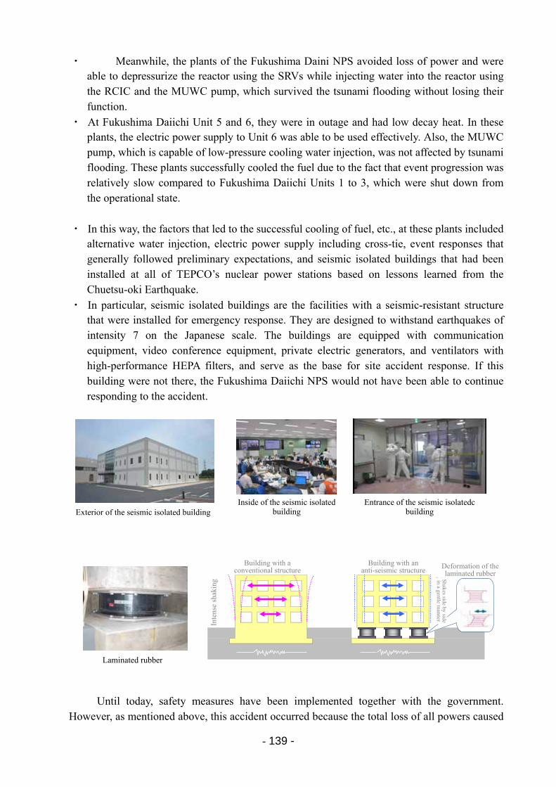
- 139 -
・ Meanwhile, the plants of the Fukushima Daini NPS avoided loss of power and were able to depressurize the reactor using the SRVs while injecting water into the reactor using the RCIC and the MUWC pump, which survived the tsunami flooding without losing their function.
・ At Fukushima Daiichi Unit 5 and 6, they were in outage and had low decay heat. In these plants, the electric power supply to Unit 6 was able to be used effectively. Also, the MUWC pump, which is capable of low-pressure cooling water injection, was not affected by tsunami flooding. These plants successfully cooled the fuel due to the fact that event progression was relatively slow compared to Fukushima Daiichi Units 1 to 3, which were shut down from the operational state.
・ In this way, the factors that led to the successful cooling of fuel, etc., at these plants included alternative water injection, electric power supply including cross-tie, event responses that generally followed preliminary expectations, and seismic isolated buildings that had been installed at all of TEPCO’s nuclear power stations based on lessons learned from the Chuetsu-oki Earthquake.
・ In particular, seismic isolated buildings are the facilities with a seismic-resistant structure that were installed for emergency response. They are designed to withstand earthquakes of intensity 7 on the Japanese scale. The buildings are equipped with communication equipment, video conference equipment, private electric generators, and ventilators with high-performance HEPA filters, and serve as the base for site accident response. If this building were not there, the Fukushima Daiichi NPS would not have been able to continue responding to the accident.
Until today, safety measures have been implemented together with the government. However, as mentioned above, this accident occurred because the total loss of all powers caused
Exterior of the seismic isolated building Inside of the seismic isolated
buildingEntrance of the seismic isolatedc
building
Laminated rubber
従来構造による建物 免震構造による建物
積層ゴムの変形ゆっ
く
りと平行に
ゆれる
はげし
くゆれる
Building with aconventional structure
Building with an anti-seismic structure Deformation of the
laminated rubber
Inte
nse
shak
ing S
hakes side by side in a gentle m
anner
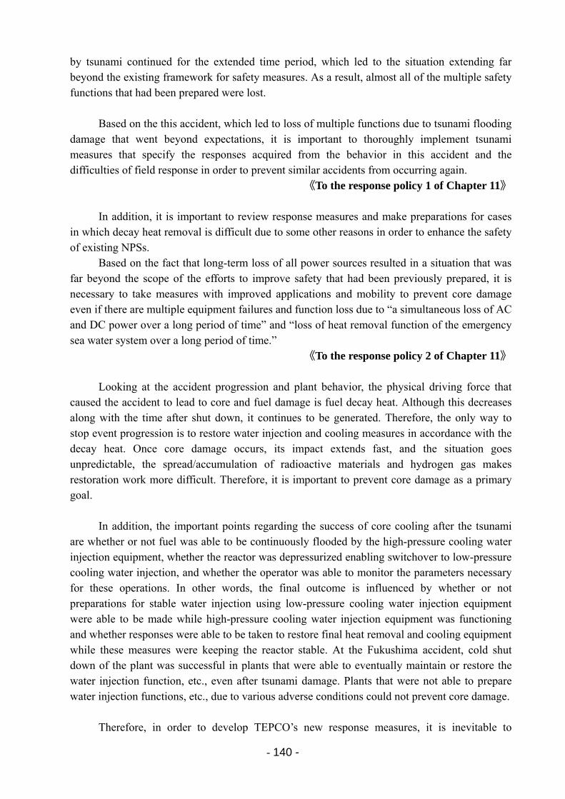
- 140 -
by tsunami continued for the extended time period, which led to the situation extending far beyond the existing framework for safety measures. As a result, almost all of the multiple safety functions that had been prepared were lost.
Based on the this accident, which led to loss of multiple functions due to tsunami flooding
damage that went beyond expectations, it is important to thoroughly implement tsunami measures that specify the responses acquired from the behavior in this accident and the difficulties of field response in order to prevent similar accidents from occurring again.
《To the response policy 1 of Chapter 11》
In addition, it is important to review response measures and make preparations for cases in which decay heat removal is difficult due to some other reasons in order to enhance the safety of existing NPSs.
Based on the fact that long-term loss of all power sources resulted in a situation that was far beyond the scope of the efforts to improve safety that had been previously prepared, it is necessary to take measures with improved applications and mobility to prevent core damage even if there are multiple equipment failures and function loss due to “a simultaneous loss of AC and DC power over a long period of time” and “loss of heat removal function of the emergency sea water system over a long period of time.”
《To the response policy 2 of Chapter 11》
Looking at the accident progression and plant behavior, the physical driving force that caused the accident to lead to core and fuel damage is fuel decay heat. Although this decreases along with the time after shut down, it continues to be generated. Therefore, the only way to stop event progression is to restore water injection and cooling measures in accordance with the decay heat. Once core damage occurs, its impact extends fast, and the situation goes unpredictable, the spread/accumulation of radioactive materials and hydrogen gas makes restoration work more difficult. Therefore, it is important to prevent core damage as a primary goal.
In addition, the important points regarding the success of core cooling after the tsunami are whether or not fuel was able to be continuously flooded by the high-pressure cooling water injection equipment, whether the reactor was depressurized enabling switchover to low-pressure cooling water injection, and whether the operator was able to monitor the parameters necessary for these operations. In other words, the final outcome is influenced by whether or not preparations for stable water injection using low-pressure cooling water injection equipment were able to be made while high-pressure cooling water injection equipment was functioning and whether responses were able to be taken to restore final heat removal and cooling equipment while these measures were keeping the reactor stable. At the Fukushima accident, cold shut down of the plant was successful in plants that were able to eventually maintain or restore the water injection function, etc., even after tsunami damage. Plants that were not able to prepare water injection functions, etc., due to various adverse conditions could not prevent core damage.
Therefore, in order to develop TEPCO’s new response measures, it is inevitable to
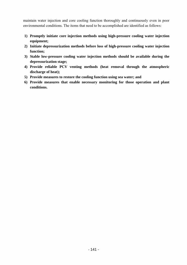
- 141 -
maintain water injection and core cooling function thoroughly and continuously even in poor environmental conditions. The items that need to be accomplished are identified as follows: 1) Promptly initiate core injection methods using high-pressure cooling water injection
equipment; 2) Initiate depressurization methods before loss of high-pressure cooling water injection
function; 3) Stable low-pressure cooling water injection methods should be available during the
depressurization stage; 4) Provide reliable PCV venting methods (heat removal through the atmospheric
discharge of heat); 5) Provide measures to restore the cooling function using sea water; and 6) Provide measures that enable necessary monitoring for those operation and plant
conditions.
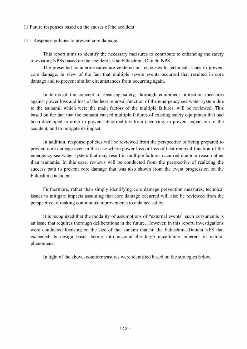
- 142 -
11 Future responses based on the causes of the accident 11.1 Response policies to prevent core damage
This report aims to identify the necessary measures to contribute to enhancing the safety of existing NPSs based on the accident at the Fukushima Daiichi NPS.
The presented countermeasures are centered on responses to technical issues to prevent core damage, in view of the fact that multiple severe events occurred that resulted in core damage and to prevent similar circumstances from occurring again.
In terms of the concept of ensuring safety, thorough equipment protection measures
against power loss and loss of the heat removal function of the emergency sea water system due to the tsunami, which were the main factors of the multiple failures, will be reviewed. This based on the fact that the tsunami caused multiple failures of existing safety equipment that had been developed in order to prevent abnormalities from occurring, to prevent expansion of the accident, and to mitigate its impact.
In addition, response policies will be reviewed from the perspective of being prepared to
prevent core damage even in the case where power loss or loss of heat removal function of the emergency sea water system that may result in multiple failures occurred due to a reason other than tsunamis. In this case, reviews will be conducted from the perspective of realizing the success path to prevent core damage that was also shown from the event progression on the Fukushima accident.
Furthermore, rather than simply identifying core damage prevention measures, technical issues to mitigate impacts assuming that core damage occurred will also be reviewed from the perspective of making continuous improvements to enhance safety.
It is recognized that the modality of assumptions of “external events” such as tsunamis is
an issue that requires thorough deliberations in the future. However, in this report, investigations were conducted focusing on the size of the tsunami that hit the Fukushima Daiichi NPS that exceeded its design basis, taking into account the large uncertainty inherent in natural phenomena.
In light of the above, countermeasures were identified based on the strategies below.
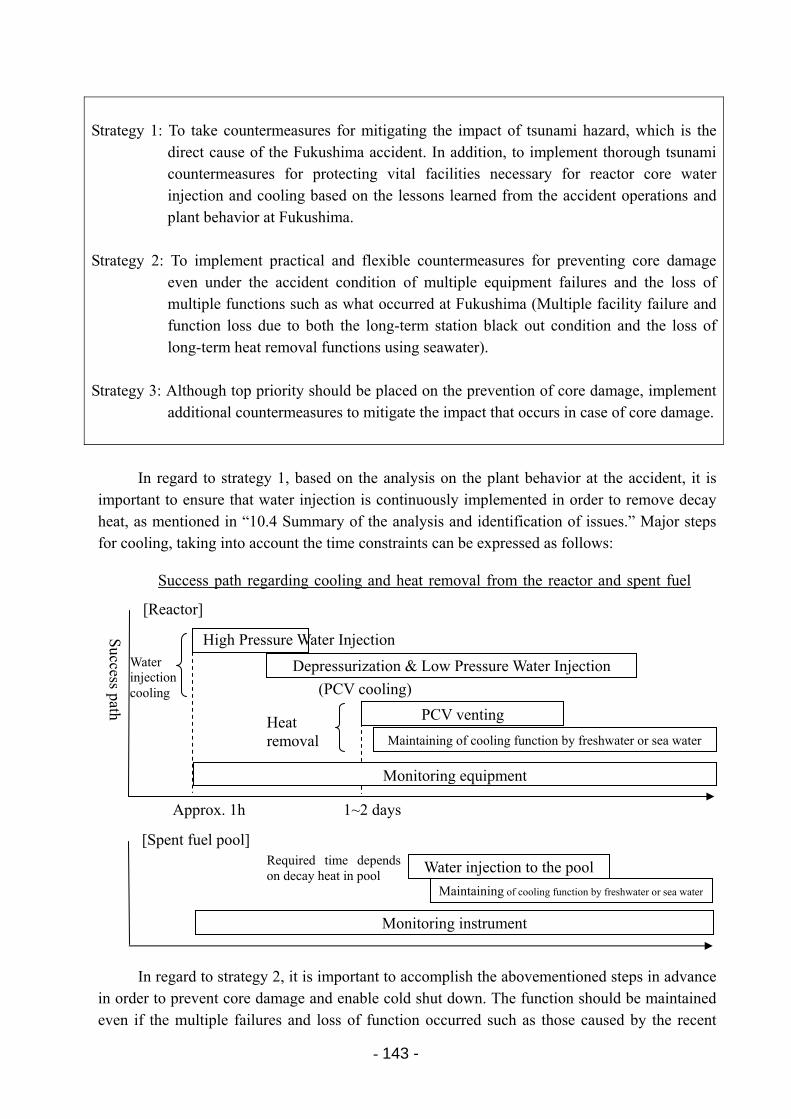
- 143 -
Strategy 1: To take countermeasures for mitigating the impact of tsunami hazard, which is the
direct cause of the Fukushima accident. In addition, to implement thorough tsunami countermeasures for protecting vital facilities necessary for reactor core water injection and cooling based on the lessons learned from the accident operations and plant behavior at Fukushima.
Strategy 2: To implement practical and flexible countermeasures for preventing core damage
even under the accident condition of multiple equipment failures and the loss of multiple functions such as what occurred at Fukushima (Multiple facility failure and function loss due to both the long-term station black out condition and the loss of long-term heat removal functions using seawater).
Strategy 3: Although top priority should be placed on the prevention of core damage, implement
additional countermeasures to mitigate the impact that occurs in case of core damage.
In regard to strategy 1, based on the analysis on the plant behavior at the accident, it is
important to ensure that water injection is continuously implemented in order to remove decay heat, as mentioned in “10.4 Summary of the analysis and identification of issues.” Major steps for cooling, taking into account the time constraints can be expressed as follows:
In regard to strategy 2, it is important to accomplish the abovementioned steps in advance in order to prevent core damage and enable cold shut down. The function should be maintained even if the multiple failures and loss of function occurred such as those caused by the recent
Success path regarding cooling and heat removal from the reactor and spent fuel
Success path
Depressurization & Low Pressure Water Injection
(PCV cooling)
PCV venting
Maintaining of cooling function by freshwater or sea water
Approx. 1h 1~2 days
Water injection cooling
Heat removal
[Reactor]
[Spent fuel pool]
Water injection to the pool
Maintaining of cooling function by freshwater or sea water
Required time depends on decay heat in pool
Monitoring equipment
Monitoring instrument
High Pressure Water Injection
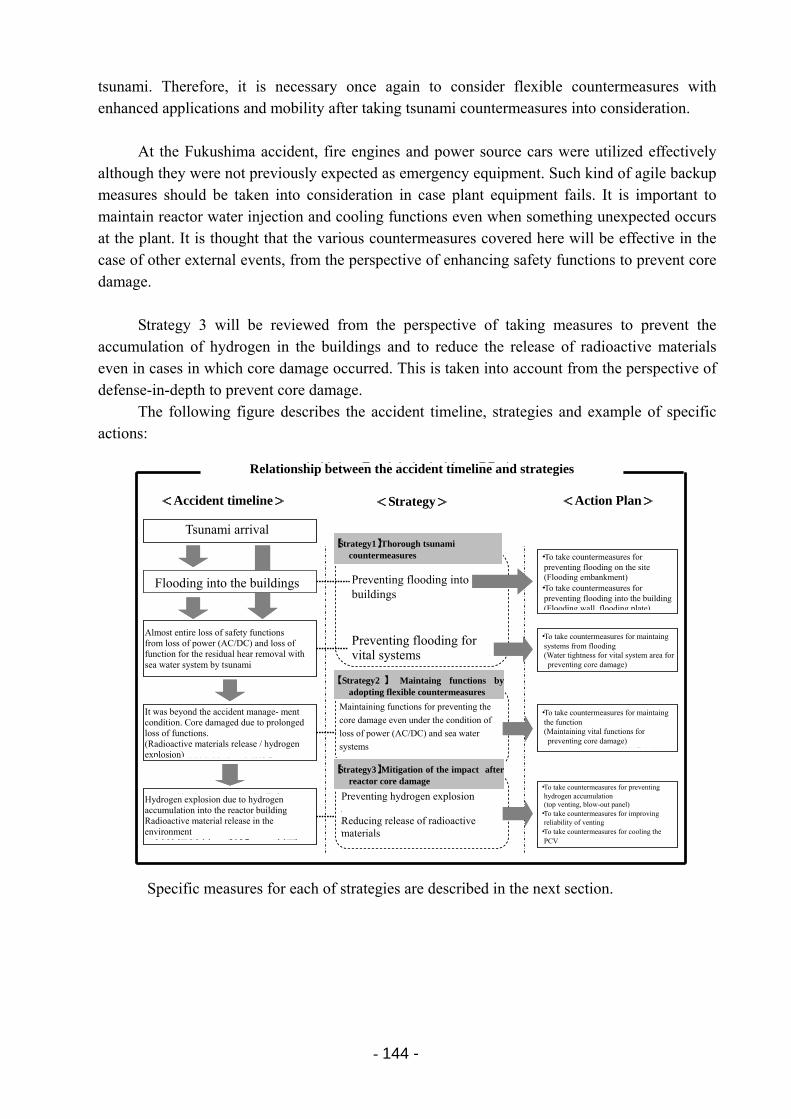
- 144 -
tsunami. Therefore, it is necessary once again to consider flexible countermeasures with enhanced applications and mobility after taking tsunami countermeasures into consideration.
At the Fukushima accident, fire engines and power source cars were utilized effectively
although they were not previously expected as emergency equipment. Such kind of agile backup measures should be taken into consideration in case plant equipment fails. It is important to maintain reactor water injection and cooling functions even when something unexpected occurs at the plant. It is thought that the various countermeasures covered here will be effective in the case of other external events, from the perspective of enhancing safety functions to prevent core damage.
Strategy 3 will be reviewed from the perspective of taking measures to prevent the
accumulation of hydrogen in the buildings and to reduce the release of radioactive materials even in cases in which core damage occurred. This is taken into account from the perspective of defense-in-depth to prevent core damage.
The following figure describes the accident timeline, strategies and example of specific actions:
Specific measures for each of strategies are described in the next section.
<事故の経過><事故の経過>
津波襲来
建屋への浸水
津波による電源(直流・交流)、海水系除熱機能の喪失による、ほぼ全ての安全機能の喪失
アクシデントマネジメントの前提を大きく超える状況。機能の回復ができなかったことから炉心損傷に至る(放射性物質放出/水素発生)
原子炉建屋への水素滞留により水素爆発
放射性物質の環境への放出
<対策の方針><対策の方針>
【方針1】徹底した津波対策
建屋への浸水防止
重要な機器の浸水防止
電源(直流・交流)、海水系の喪失を前提として、その場合でも炉心損傷を防止する機能の確保策
水素爆発の防止
放射性物質の放出低減
【方針2】柔軟な機能代替策
【方針3】炉心損傷時の影響緩和策
<具体化の方向性><具体化の方向性>
○敷地への浸水低減策(防潮堤)
○建屋浸水対策(防潮壁、防潮板)
○機器の浸水対策(炉心損傷防止のための重要機器エリアの水密化)
○機能確保策(炉心損傷防止のためのサクセスパスの機能確保)
○水素滞留防止策(トップベント、ブローアウトパネル)
○ベント信頼性向上策
○格納容器冷却対策
事故経過と対応方針の関連
<事故の経過><事故の経過>
津波襲来
建屋への浸水
津波による電源(直流・交流)、海水系除熱機能の喪失による、ほぼ全ての安全機能の喪失
アクシデントマネジメントの前提を大きく超える状況。機能の回復ができなかったことから炉心損傷に至る(放射性物質放出/水素発生)
原子炉建屋への水素滞留により水素爆発
放射性物質の環境への放出
<対策の方針><対策の方針>
【方針1】徹底した津波対策
建屋への浸水防止
重要な機器の浸水防止
電源(直流・交流)、海水系の喪失を前提として、その場合でも炉心損傷を防止する機能の確保策
水素爆発の防止
放射性物質の放出低減
【方針2】柔軟な機能代替策
【方針3】炉心損傷時の影響緩和策
<具体化の方向性><具体化の方向性>
○敷地への浸水低減策(防潮堤)
○建屋浸水対策(防潮壁、防潮板)
○機器の浸水対策(炉心損傷防止のための重要機器エリアの水密化)
○機能確保策(炉心損傷防止のためのサクセスパスの機能確保)
○水素滞留防止策(トップベント、ブローアウトパネル)
○ベント信頼性向上策
○格納容器冷却対策
事故経過と対応方針の関連Relationship between the accident timeline and strategies
<Accident timeline> <Strategy> <Action Plan>
Tsunami arrival
Flooding into the buildings
Almost entire loss of safety functions from loss of power (AC/DC) and loss of function for the residual hear removal with sea water system by tsunami
It was beyond the accident manage- ment condition. Core damaged due to prolonged loss of functions. (Radioactive materials release / hydrogen explosion)
Hydrogen explosion due to hydrogen accumulation into the reactor building Radioactive material release in the environment
【Strategy1】Thorough tsunami countermeasures
【 Strategy2 】 Maintaing functions byadopting flexible countermeasures
【Strategy3】Mitigation of the impact after reactor core damage
Preventing flooding intobuildings
Preventing flooding for vital systems
Maintaining functions for preventing the
core damage even under the condition of
loss of power (AC/DC) and sea water
systems
Preventing hydrogen explosion Reducing release of radioactive materials
・To take countermeasures for preventing flooding on the site (Flooding embankment) ・To take countermeasures for preventing flooding into the building(Flooding wall, flooding plate)
・To take countermeasures for maintaing systems from flooding (Water tightness for vital system area for preventing core damage)
・To take countermeasures for maintaing the function (Maintaining vital functions for preventing core damage)
・To take countermeasures for preventing hydrogen accumulation (top venting, blow-out panel) ・To take countermeasures for improving
reliability of venting ・To take countermeasures for cooling the
PCV
- 145 -
11.2 Specific countermeasures in consideration of the Fukushima accident
In order to apply the lessons learned from the Fukushima accident to the nuclear industry, it is important to take thorough anti-flooding measures for buildings and to develop countermeasures based on the necessary requirements to prevent core damage in advance.
In addition to tsunami preparations, the specific response measures for each step until successful cooling, which were mentioned above, were investigated. See [Attachment 11-1, 2] for the review results. Here, mainly the countermeasures on facilities focusing on preventing core damage in advance are described. For actual effective usage, it is necessary to ensure the enhancement of management aspects, such as procedures and training. In addition, countermeasures to be taken after there is core damage have also been investigated, as a precaution, and further investigations and improvements will be conducted in the future.
(1) Thorough flooding countermeasures for buildings
As mentioned before, the Fukushima accident was caused by the tsunami flowing into the major buildings. Tsunami flooded important equipment (power equipment, etc.) and caused the multiple failures of equipment and loss of function. It is therefore important to take measures to prevent the flooding of areas where important equipment and effective equipment for preventing core damage are installed, including those to be implemented in the mid to long-term.
[Action plan 1: Measures to prevent flooding on the site] Since the prevention of flooding of the power station contributes to mitigating the tsunami
impact and preventing extensive tsunami damage, sea walls will be installed.
[Action plan 1: Measures to prevent flooding of buildings] Installation of tidal board and wall at the openings of air intakes for key electrical equipment
installed on the outer walls of buildings, etc., which was the tsunami flooding route, will prevent water from entering from outside. In addition, in order to prevent water from entering the buildings, the water-tightness of the doors will be improved, and the wall penetration seals that are installed to pass through pipes and cables will be made waterproof to prevent flooding.
(2) High-pressure cooling water injection equipment
When the plant shuts down from an operational state due to an accident, equipment that can inject water at high pressure is initially required as the pressure of the RPV is high. In addition, as all the motor-driven high-pressure cooling water injection pumps could not be used in this accident due to the loss of AC power, steam-driven high-pressure cooling water injection equipment is important. Specifically, these include the IC (cooling function only) and the HPCI for Unit 1 and the RCIC and the HPCI for Units 2 and 3. This time, Units 2 and 3 succeeded in operating the RCIC over the long period of time. However, it is necessary to maintain DC power in order to reliably start up the RCIC and the HPCI without fail.

- 146 -
[Action plan 1: Measures to prevent flooding on the site] Therefore, in addition to the thorough tsunami countermeasures described in the previous
section, waterproofing measures at the locations of the high-pressure cooling water injection equipment and DC power required for start up (supply routes such as the battery room and main bus panel, etc) will be thoroughly implemented in order to protect them from water (prevent flooding). Regarding the main components, such as pumps, it is fundamentally difficult to change the installation location due to design restrictions such as its position in relation to the water source, etc. Since power sources might be relocated, one option is to move the power sources to high elevation instead of waterproofing.
[Action plan 2: Establishment of functions through flexible countermeasures (manual startup of steam-driven high-pressure cooling water injection equipment)]
A countermeasure with enhanced application and mobility is to provide a method to enable people to manually startup the turbine-driven high-pressure cooling water injection equipment (HPCI or RCIC) in the field in case it does not start up. Since the high-pressure cooling water injection equipment must be able to start up immediately, the top priority is for it to respond in a short period of time. Therefore, it will be effective to consider measures to inject water manually into the reactor even in the case if the high-pressure cooling water injection equipment cannot be started up from the MCR. That is, to manually open steam inlet valves, etc., of the high-pressure cooling water injection equipment in the field, and then to activate pumps by manually starting up the steam driven turbine.
[Action plan 2: Establishment of functions through flexible countermeasures (use of motor-driven high-pressure cooling water injection equipment)]
As an additional countermeasure, it would be necessary to take measures to start up a limited number of high-pressure water injection equipment by using portable equipment. The portable equipment such as power source cars would be stored and charged in a safe place usually. In case if original power supply equipment malfunctions, the portable equipment can be moved to the plant urgently.
The target of this countermeasure should be one with a simple startup condition. In other words, it would be better to select and start up high-pressure cooling water injection equipment with few associated equipment. (For instance, it is better to avoid equipment that requires another pump to supply cooling water for start up the equipment.).
Specifically, it will be effective to take measures to start up the SLC (or control rod drive hydraulic control system) as early as possible. It is necessary to consider countermeasures to prevent the pump from directly losing its function due to flooding for these devices as well (waterproofing of the pump installation area). In particular, since the SLC is located inside the Reactor Building, which is highly airtight, it is considered to be most advantageous as a tsunami countermeasure.
In order to utilize these measures, it is necessary to waterproof the power equipment including EDGs. In addition, as a countermeasure for the loss of electric power supply inside the plant, it is necessary to plan countermeasures in advance to provide AC power including procedures. Then for prompt connection of power source cars from outside, necessary equipment should be well prepared such as a set of transformer, circuit breaker, and cables to the equipment
- 147 -
rather than just simply sending a power source car. In addition, a sufficient amount of power source should be prepared on high elevation
outside the building in order to enhance diversity for EDGs. In regard to the SLC, it is necessary in advance to establish measures to maintain a water source including water for replenishment, since the system cannot store a large amount of water in itself.
(3) Depressurization equipment
In order to ultimately achieve plant heat removal and cooling, depressurization of the RPV is required. In this accident, there was difficulty in smoothly opening the SRVs in some plants for depressurization for the RPV. This is because there was a lack of DC power necessary for operating the SRV due to the loss of power.
[Action plan 1: Measures to prevent flooding of equipment] Therefore, measures to provide DC power (waterproofing of the battery room and main
bus panel installation area, etc. (or relocation)) are considered to be necessary.
[Action plan 2: Establishment of functions through flexible countermeasures (Establishment of a drive source for SRVs)]
In terms of countermeasures with enhanced application and mobility, it is necessary to charge and store backup batteries in a safe place away from the plant so that they can be urgently brought to the station in order to supply electricity when needed.
In the depressurization operation during the accident at the Fukushima Daiichi NPS, there was sufficient nitrogen gas required to operate the SRV. However, it would be necessary to prepare backup nitrogen gas cylinders, assuming a decrease in operational air pressure of the air operated valves.
(4) Low-pressure cooling water injection equipment
Low-pressure cooling water injection equipment includes the emergency low-pressure cooling water injection system equipment as well as the MUWC and the FP. In this case, the motor-driven emergency low-pressure cooling water injection system equipment, which had been expected to function, did not work due to the total loss of AC power. The MUWC, whose pipes had been connected to enable water injection to the reactor as so-called AM equipment, also lost its function due to water damage to the electric motor.
Therefore, the only low-pressure cooling water injection equipment that was able to be started up was the diesel-drive fire pump. However, as mentioned above, this was also not able to be used sufficiently. As a result, fire engines that were originally prepared for a different purpose were used for alternative low-pressure cooling water injection equipment. Because of the reasons such as that this method of injecting water into the reactor was not sufficiently reviewed in advance, and that it was also exposed to harsh environments, it was difficult to prepare in a short period of time stable and reliable low-pressure cooling water injection equipment, which prevented a smooth switchover to the low-pressure cooling water injection.
- 148 -
For water injection using low-pressure cooling water injection equipment, there is some time available for preparations, since high-pressure cooling water injection is used for initial response.
[Action plan 1: Measures to prevent the flooding of equipment] The top priorities in terms of measures to provide low-pressure cooling water injection are
to protect the FP pump and the MUWC pump, including the original installed diesel-drive fire pump, from flooding and to restore them from fuel depletion and power loss. Therefore, it is necessary to waterproof the installation location of the FP pump, to provide fuel for the diesel-driven fire pump (as well as the fuel delivery method), to provide power for the motor-driven fire pump using power source cars, etc., and to waterproof the control battery location.
In addition, it is necessary to waterproof the pump area for the MUWC, as well as to waterproof electrical equipment including the EDG or to provide AC power using power source cars, etc.
When AC power is lost, it is considered that the diesel-driven fire pump should be
preferentially used. However, once AC power is provided, the MUWC system pump can provide a more stable water supply since there is no need for fuel replenishment, etc. Much more time is available until using the low-pressure cooling water injection system compared to the high-pressure cooling water injection system. Therefore, it is important to assess the situation and to choose the more stable injection method.
[Action plan 2: Establishment of functions through flexible countermeasures (Establishment of power for alternative water injection systems)]
As a countermeasure that will serve as further preparation for an accident, it is necessary to charge and store spare batteries in a separate safe place in preparation for a decrease in the performance of the original batteries for controlling the abovementioned diesel-driven fire pump. It is also necessary to consider and prepare measure so that they can be brought to the field at any time.
In addition, in preparation for cases in which power to the MUWC pump, etc., is lost, a sufficiently capable power source should be prepared on high elevation outside the building. This can be implemented as a diverse measure in addition to the provision of power source cars and EDG, as described in the section regarding “high-pressure cooling water injection equipment.”
[Action plan 2: Establishment of functions through flexible countermeasures (Establishment of water injection means using fire engines)]
In addition, water injection to the reactor will be conducted using fire engines if all of the original installed low-pressure cooling water injection equipment cannot be used. Normally, the fire engines will be placed on standby in a safe place. If there is the risk of a situation in which the original installed pumps cannot be used, the fire engines will be promptly moved to the plant. Then the configuration will be lined up for water injection to the reactor by injecting water into an external connecting port.
To provide sufficient water source can be an issue that is common to all low-pressure
- 149 -
cooling water injection equipment. In the case of the Fukushima accident, pumps that could be used for reactor water injection were limited to the diesel-driven fire pump and fire engines. The fact that a large freshwater supply could not be provided and the fact that water could not be directly pumped up from the sea due to the difference in the elevation in the initial stages are considered as a part of the reasons of taking much time to inject water to the reactor.
[Action plan 2: Establishment of functions through flexible countermeasures (Establishment of a water source)]
There are many types of low-pressure cooling water injection equipment. Its water source differs depending on the pump used. Therefore, it is important to verify in advance the possibility of pumping up sea water and to establish the related procedures for a maintaining water source. Pumps that are able to be used may be limited depending on the situation. Therefore, it is also necessary to verify measures to access water from tanks that can serve as a water source in advance. In addition, there have been some cases in which the pipes of the FP were damaged by the tsunami and collision of floating debris in this accident. Hence it is also important to prepare a route map for the FP pipes for easily identifying damaged locations.
(5) Heat removal and cooling equipment
1) PCV venting (S/C venting)
When conducting low-pressure cooling water injection, the reactor pressure is released to the S/C using the SRV. When the reactor water level decreases, water is supplied using low-pressure water injection equipment. Eventually, both the pressure and temperature of the S/C increase. If sea water cannot be used as a cooling source under such circumstances, it is necessary to vent the S/C to use air as a cooling source and to release the pressure and heat of the S/C to the atmosphere.
In this accident, the pressure of the Fukushima Daiichi Unit 2 S/C increased to around its design pressure, and the temperature of the S/C increased to over 100˚C. This is because heat removal from the S/C was not possible, although reactor heat was released to the S/C, causing heat to be kept inside. In this accident, a line up of the PCV vent line could not be performed easily. As a result, it took a longer time than expected.
Venting from the S/C when there was still no fuel damage basically signifies active venting without the discharge of radioactive materials. This is important for maintaining the integrity of the PCV in addition to cooling the reactor. In order to complete the venting of the S/C, it is necessary to open a motor operated valve and an air operated valve.
[Action plan 1: Measures to prevent the flooding of equipment] Therefore, in order to ensure venting from the S/C from the standpoint of heat removal, first
priority is maintaining AC power and air for operation. Specifically, it is necessary to waterproof the power equipment including EDG and to provide portable air compressors (or gas cylinders) to provide air for operation.
- 150 -
[Action plan 2: Establishment of functions through flexible countermeasures (diversification of operations to open the air operated valve)]
As a countermeasure for maintain power supply, it is necessary to have power source cars as mentioned above. In addition, it is important to install portable generators for solenoid valves for air operated valves in a safe place. The procedure for promptly bringing in and utilizing them should be established for emergency. In addition, since the response is ultimately conducted by people, the design of the air operated valve as well as the motor operated valve would be modified for manual operation.
2) Heat removal through the shutdown cooling mode (RHR)
At Fukushima Daiichi Units 5 and 6 and Fukushima Daini Units 1, 2, and 4, cold shut
down could be finally achieved. However, during their emergency response, sea water systems for the RHR, etc., lost their functions that were designed as an ultimate heat sink.
In these units, emergency sea water systems as an ultimate heat sink was restored by connecting power source, installing alternative pumps, repairing or replacing motors, and others.
[Action plan 1: Measures to prevent the flooding of equipment] The RHR pump is installed inside the reactor building. Since it is a vertical pump, it is
basically resistant to tsunamis. It is necessary to maintain power supply system including EDGs through tsunami countermeasures (waterproofing, etc.). In addition, preparation for a spare replacement motor would be effective in order to activate pumps for emergency sea water systems and intermediate cooling systems.
[Action plan 2: Establishment of functions through flexible countermeasures (Establishment of a power source for the RHR)]
As a flexible countermeasure in preparation for a loss of power, a power source with sufficient capacity will be installed as diversification of the EDG on high elevation outside the building.
[Action plan 2: Establishment of functions through flexible countermeasures (diversification of heat exchanger equipment)]
In terms of measures with enhanced applications and mobility, the provision of a portable mobile heat exchanger (pump, heat exchanger set) that includes power source and cooling equipment will be considered in order to conduct quicker restoration.
3) Heat removal from spent fuel pool
[Action plan 1: Measures to prevent the flooding of equipment] The FPC is installed inside the reactor building and is generally resistant to tsunamis.
However, since it is a horizontal-type pump, countermeasures should be based on tsunami countermeasures (waterproofing) of the pump room and power system. In terms of power, the provision of power source cars, etc., will be considered as a backup measure.
Since it is currently difficult to measure the water level and temperature once the water
- 151 -
level decreases. A device that can measure the water level and temperature of the deep part of the pool will be installed in the pool so that more reliable cooling can be implemented.
[Action plan 2: Establishment of functions through flexible countermeasures (diversification of water injection methods)]
Based on the event progress in the Fukushima accident, a longer coping time for implementing responses to prevent fuel damage inside the SFP can be available, since flexible measures with enhanced application and mobility, preparation for fire engines and use of the FP pipes will be considered for back-up water injection functions.
(6) Maintaining power for monitoring instruments
In this accident, both AC power and DC power were lost. At Units 1 and 2, which suffered core damage, monitoring instruments lost their functions. In addition, in Unit 3, which was able to use DC power, operators had to save power by turning off unnecessary instruments, etc. for utilizing as long as possible. The loss of monitoring function for the operating condition of each equipment could cause errors and delays in decisions and responses. Hence, temporary batteries were connected to restore the instruments, although certain amount of time was necessary for the restoration.
[Action plan 1: Measures to prevent the flooding of equipment] Therefore, it is necessary to take measures from the tsunami to protect power sources for
equipment that is necessary for cold shut down (waterproofing of the battery room and main bus panel installation area, or their relocation).
[Action plan 2: Establishment of functions through flexible countermeasures (diversification of power sources for instruments)]
In addition, in order to enhance application and mobility, it is necessary to provide portable batteries for DC power. In addition, it would be necessary to prepare power source cars and portable chargers for long-term use.
(7) Measures for mitigating impact after core damage
In this accident, a large amount of hydrogen and radioactive materials were released
inside the PCV as a result of core damage. The hydrogen leaked into the reactor building and led to the release of radioactive materials into the environment.
In addition, due to the explosion of the hydrogen that is considered to have leaked into the reactor building from the PCV, the function to contain radioactive materials was lost and restoration activities themselves became substantially difficult.
The primary way to prevent the adverse impacts caused by core damage is to prevent core damage itself. From the perspective of defense-in-depth, it is important to take further measures in case core damage does occur.
The measures for mitigating impact after core damage will be improved future accident investigations.
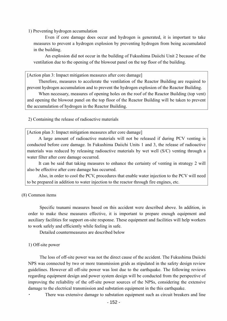
- 152 -
1) Preventing hydrogen accumulation
Even if core damage does occur and hydrogen is generated, it is important to take measures to prevent a hydrogen explosion by preventing hydrogen from being accumulated in the building.
An explosion did not occur in the building of Fukushima Daiichi Unit 2 because of the ventilation due to the opening of the blowout panel on the top floor of the building.
[Action plan 3: Impact mitigation measures after core damage] Therefore, measures to accelerate the ventilation of the Reactor Building are required to
prevent hydrogen accumulation and to prevent the hydrogen explosion of the Reactor Building. When necessary, measures of opening holes on the roof of the Reactor Building (top vent)
and opening the blowout panel on the top floor of the Reactor Building will be taken to prevent the accumulation of hydrogen in the Reactor Building.
2) Containing the release of radioactive materials
[Action plan 3: Impact mitigation measures after core damage] A large amount of radioactive materials will not be released if during PCV venting is
conducted before core damage. In Fukushima Daiichi Units 1 and 3, the release of radioactive materials was reduced by releasing radioactive materials by wet well (S/C) venting through a water filter after core damage occurred.
It can be said that taking measures to enhance the certainty of venting in strategy 2 will also be effective after core damage has occurred.
Also, in order to cool the PCV, procedures that enable water injection to the PCV will need to be prepared in addition to water injection to the reactor through fire engines, etc.
(8) Common items
Specific tsunami measures based on this accident were described above. In addition, in order to make these measures effective, it is important to prepare enough equipment and auxiliary facilities for support on-site response. These equipment and facilities will help workers to work safely and efficiently while feeling in safe.
Detailed countermeasures are described below 1) Off-site power
The loss of off-site power was not the direct cause of the accident. The Fukushima Daiichi NPS was connected by two or more transmission grids as stipulated in the safety design review guidelines. However all off-site power was lost due to the earthquake. The following reviews regarding equipment design and power system design will be conducted from the perspective of improving the reliability of the off-site power sources of the NPSs, considering the extensive damage to the electrical transmission and substation equipment in the this earthquake.
・ There was extensive damage to substation equipment such as circuit breakers and line
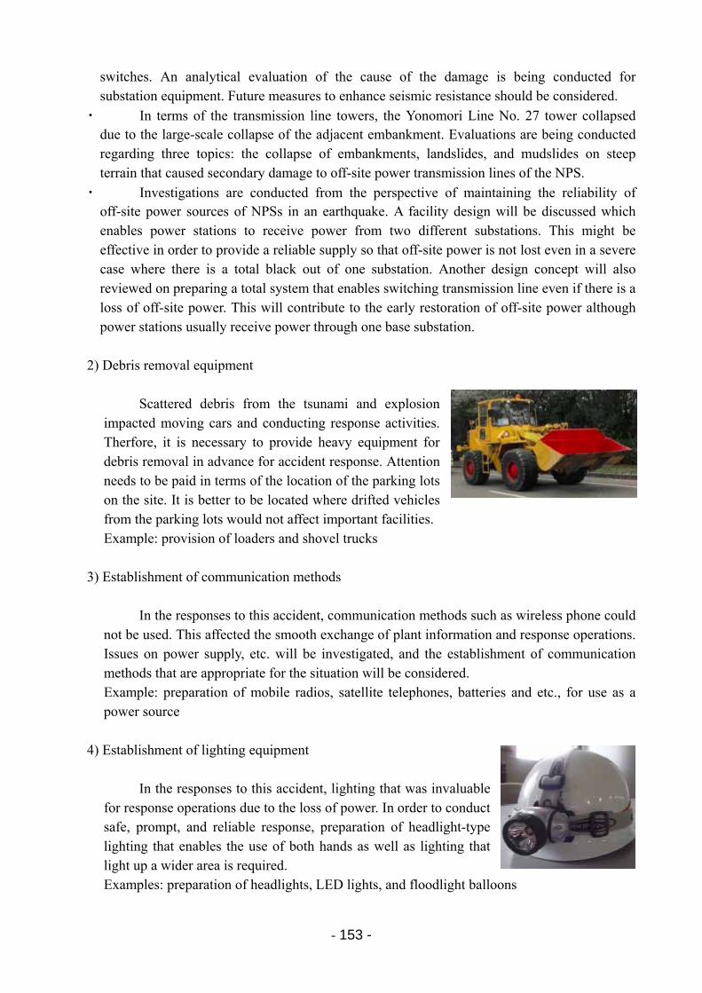
- 153 -
switches. An analytical evaluation of the cause of the damage is being conducted for substation equipment. Future measures to enhance seismic resistance should be considered.
・ In terms of the transmission line towers, the Yonomori Line No. 27 tower collapsed due to the large-scale collapse of the adjacent embankment. Evaluations are being conducted regarding three topics: the collapse of embankments, landslides, and mudslides on steep terrain that caused secondary damage to off-site power transmission lines of the NPS.
・ Investigations are conducted from the perspective of maintaining the reliability of off-site power sources of NPSs in an earthquake. A facility design will be discussed which enables power stations to receive power from two different substations. This might be effective in order to provide a reliable supply so that off-site power is not lost even in a severe case where there is a total black out of one substation. Another design concept will also reviewed on preparing a total system that enables switching transmission line even if there is a loss of off-site power. This will contribute to the early restoration of off-site power although power stations usually receive power through one base substation.
2) Debris removal equipment
Scattered debris from the tsunami and explosion
impacted moving cars and conducting response activities. Therfore, it is necessary to provide heavy equipment for debris removal in advance for accident response. Attention needs to be paid in terms of the location of the parking lots on the site. It is better to be located where drifted vehicles from the parking lots would not affect important facilities. Example: provision of loaders and shovel trucks
3) Establishment of communication methods
In the responses to this accident, communication methods such as wireless phone could not be used. This affected the smooth exchange of plant information and response operations. Issues on power supply, etc. will be investigated, and the establishment of communication methods that are appropriate for the situation will be considered. Example: preparation of mobile radios, satellite telephones, batteries and etc., for use as a power source
4) Establishment of lighting equipment
In the responses to this accident, lighting that was invaluable for response operations due to the loss of power. In order to conduct safe, prompt, and reliable response, preparation of headlight-type lighting that enables the use of both hands as well as lighting that light up a wider area is required. Examples: preparation of headlights, LED lights, and floodlight balloons
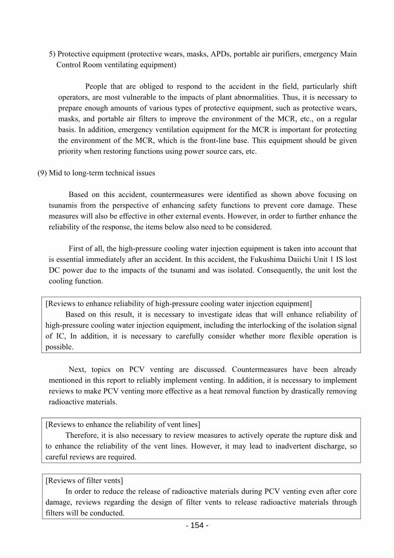
- 154 -
5) Protective equipment (protective wears, masks, APDs, portable air purifiers, emergency Main
Control Room ventilating equipment)
People that are obliged to respond to the accident in the field, particularly shift operators, are most vulnerable to the impacts of plant abnormalities. Thus, it is necessary to prepare enough amounts of various types of protective equipment, such as protective wears, masks, and portable air filters to improve the environment of the MCR, etc., on a regular basis. In addition, emergency ventilation equipment for the MCR is important for protecting the environment of the MCR, which is the front-line base. This equipment should be given priority when restoring functions using power source cars, etc.
(9) Mid to long-term technical issues
Based on this accident, countermeasures were identified as shown above focusing on tsunamis from the perspective of enhancing safety functions to prevent core damage. These measures will also be effective in other external events. However, in order to further enhance the reliability of the response, the items below also need to be considered.
First of all, the high-pressure cooling water injection equipment is taken into account that
is essential immediately after an accident. In this accident, the Fukushima Daiichi Unit 1 IS lost DC power due to the impacts of the tsunami and was isolated. Consequently, the unit lost the cooling function.
[Reviews to enhance reliability of high-pressure cooling water injection equipment] Based on this result, it is necessary to investigate ideas that will enhance reliability of
high-pressure cooling water injection equipment, including the interlocking of the isolation signal of IC, In addition, it is necessary to carefully consider whether more flexible operation is possible.
Next, topics on PCV venting are discussed. Countermeasures have been already
mentioned in this report to reliably implement venting. In addition, it is necessary to implement reviews to make PCV venting more effective as a heat removal function by drastically removing radioactive materials.
[Reviews to enhance the reliability of vent lines] Therefore, it is also necessary to review measures to actively operate the rupture disk and
to enhance the reliability of the vent lines. However, it may lead to inadvertent discharge, so careful reviews are required.
[Reviews of filter vents] In order to reduce the release of radioactive materials during PCV venting even after core
damage, reviews regarding the design of filter vents to release radioactive materials through filters will be conducted.
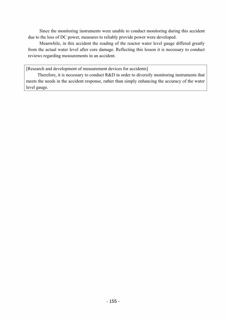
- 155 -
Since the monitoring instruments were unable to conduct monitoring during this accident
due to the loss of DC power, measures to reliably provide power were developed. Meanwhile, in this accident the reading of the reactor water level gauge differed greatly
from the actual water level after core damage. Reflecting this lesson it is necessary to conduct reviews regarding measurements in an accident.
[Research and development of measurement devices for accidents] Therefore, it is necessary to conduct R&D in order to diversify monitoring instruments that
meets the needs in the accident response, rather than simply enhancing the accuracy of the water level gauge.
- 156 -
12. Conclusion
TEPCO has been pursuing the reduction of the risks of nuclear disasters from various
perspectives. However, as mentioned in the report, the measures that we had prepared consequently turned out to be insufficient. We deeply apologize that this resulted in the extremely serious accident in which radioactive materials were released.
This report intended to identify lessons as the central player of the accident based on what
we have experienced data that have been collected, etc. As a first step, it describes the facts of the investigations that have been verified so far and identified countermeasures to prevent core damage. These items will be incorporated in TEPCO’s nuclear power plants, but we hope that many people in the nuclear power industry will read through the report and use it to enhance safety in BWR plants both in Japan and abroad.
We will continue to conduct further investigations and verifications regarding new topics
such as “the release of radioactive materials,” “radiation control,” “human resources,” “material procurement,” and “information disclosure/information provision,” etc., in addition to the topics that we have covered in this report, in order to learn from them.
Again, we sincerely apologize for the anxiety and inconvenience caused to the local
residents around the power station, the residents of Fukushima Prefecture, and the entire society. We would also like to express our gratitude towards the government, relevant organizations, and manufacturers, etc., for their support and cooperation in resolving this accident.
End