Embed Size (px)
Citation preview
FUJITSU Server PRIMEQUEST 2000 Series
Design Guide
CA92344-0696-07

PRIMEQUEST 2000 Series Design Guide
Table of Contents
Preface 1. PRIMEQUEST Overview 2. Basic Hardware Configuration 3. Hardware Configuration Design 4. Operation Management Design 5. OS/Support Appendices
Copyright 2016-2017 FUJITSU LIMITED 1

PRIMEQUEST 2000 Series Design Guide
Preface
About This Manual Contents of This Manual
This manual describes the concepts of system design and notes for users of the PRIMEQUEST 2000 series.
• For details on the operation of the main unit and other information, refer to the manuals for the PRIMEQUEST 2000 series main unit.
• For details on the operating environment of the software, refer to the website of each software.
• For details on virtualization, refer to the document of each virtualization software.
Organization of Manuals
The following figure shows the organization of manuals for the PRIMEQUEST 2000 series.
Copyright 2016-2017 FUJITSU LIMITED
Operation Installation Design
Linux (RHEL) Installation Guide Linux (RHEL) Operation Guide Design Guide Linux (RHEL) Design Guide
2

PRIMEQUEST 2000 Series Design Guide
Preface Symbols in This Manual
The following table shows the meaning of the symbol used in this manual.
Abbreviations in This Manual
Copyright 2016-2017 FUJITSU LIMITED
Name Abbreviation
PRIMEQUEST 2400E2 4 socket model
PRIMEQUEST 2000 series PRIMEQUEST
PRIMEQUEST 2400E3
PRIMEQUEST 2800B2
8 socket model PRIMEQUEST 2800B3
PRIMEQUEST 2800E2
PRIMEQUEST 2800E3
Microsoft® Windows Server® 2012 R2 Standard Windows Server 2012 R2
Windows Microsoft® Windows Server® 2012 R2 Datacenter
Microsoft® Windows Server® 2012 Standard Windows Server 2012
Microsoft® Windows Server® 2012 Datacenter
Red Hat® Enterprise Linux® 6 (for Intel64) RHEL 6 (for Intel64) RHEL 6 RHEL
Linux Red Hat® Enterprise Linux® 7 (for Intel64)
RHEL 7 (for Intel64) RHEL 7
SUSE® Linux® Enterprise Server 11 SLES 11 SLES Linux SUSE® Linux® Enterprise Server 12 SLES 12
Symbol Meaning
Indicates the page or document to refer to.
3

PRIMEQUEST 2000 Series Design Guide
Preface
Copyright 2016-2017 FUJITSU LIMITED
Name Abbreviation
Oracle® Linux 7 Update 2 Oracle Linux Linux
Oracle® VM Server for x86 Release 3.4 Oracle VM
VMware vSphere® 5.5 VMware 5.5
VMware VMware vSphere® 6
VMware vSphere® 6.5 VMware 6
PRIMEQUEST 2000 Series Hardware Installation Manual Hardware Installation Manual
PRIMEQUEST 2000 Series General Description General Description
PRIMEQUEST 2000 Series Installation Manual Installation Manual
PRIMEQUEST 2000 Series Administration Manual Administration Manual
PRIMEQUEST 2000 Series Tool Reference Tool Reference
PRIMEQUEST 2000 Series Linux Design Guide -Red Hat Enterprise Linux- Linux (RHEL) Design Guide
PRIMEQUEST 2000 Series Linux Installation Guide -Red Hat Enterprise Linux- Linux (RHEL) Installation Guide
PRIMEQUEST 2000 Series Linux Operation Guide -Red Hat Enterprise Linux- Linux (RHEL) Operation Guide
• Microsoft, Windows, Windows Server, Active Directory, and other Microsoft product names are either registered trademarks or trademarks of Microsoft Corporation in the United States and/or other countries.
• Linux® is the registered trademark of Linus Torvalds in the U.S. and other countries.
• Red Hat and Red Hat Enterprise Linux are trademarks of Red Hat, Inc., registered in the U.S. and other countries.
• Intel and Xeon are trademarks of Intel Corporation in the United States and/or other countries.
• VMware and other VMware product names are registered trademarks or trademarks of VMware, Inc. in the United States and/or other countries.
• NetVault is a trademark or registered trademark of Dell, Inc. in the United States and/or other countries.
• Oracle and Java are the registered trademarks of Oracle Corporation and its subsidiaries/related companies in the United States and other countries.
• Arcserve is a trademark or registered trademark of Arcserve (USA), LLC.
• SUSE is a trademark or registered trademark of SUSE LLC. in the United States and other countries.
• PRIMECLUSTER is a registered trademark of Fujitsu Limited.
• Other company names and product names are the trademarks or registered trademarks of their respective owners.
4

PRIMEQUEST 2000 Series Design Guide Copyright 2016-2017 FUJITSU LIMITED
1. PRIMEQUEST Overview
This chapter describes the overview of PRIMEQUEST.
For details, refer to "General Description".
5

PRIMEQUEST 2000 Series Design Guide
1.1 Product Lineup
Copyright 2016-2017 FUJITSU LIMITED
Core servers that combine the reliability of a mainframe and the cost efficiency of an open server to support mission critical operations
Highly-reliable servers that are based on the latest Intel architecture
Up to 1 partition 2800B2:Up to 8 CPUs and 144 cores 2800B3:Up to 8 CPUs and 192 cores
Up to 16 PCIe slots
Up to 4 partitions 2800E2:Up to 8 CPUs and 144 cores 2800E3:Up to 8 CPUs and 192 cores
Up to 56 PCIe slots
Up to 2 partitions 2400E2:Up to 4 CPUs and 72 cores 2400E3:Up to 4 CPUs and 96 cores
Up to 56 PCIe slots
For Enterprise
For Business
PRIMEQUEST
2800B2
PRIMEQUEST
2800B3
PRIMEQUEST
2400E2
PRIMEQUEST
2400E3
PRIMEQUEST
2800E2
PRIMEQUEST
2800E3
6

PRIMEQUEST 2000 Series Design Guide
1.2 Specifications (1/2) Item PRIMEQUEST 2000 series
Purpose Business Enterprise
Model name 2800B2 2400E2 2800E2
CPU Type Intel® Xeon® Processor E7 v3 Family
Number of cores (*1) 4/10/16/18
Maximum SMP (sockets/cores) (*1) 8/144 4/72 8/144
Maximum number of partitions 1 2 4
Memory
Supported DIMMs 8GB/16GB/32GB/64GB
Maximum memory capacity (*1) 12TB (64GB DIMM x 192) 6TB (64GB DIMM x 96)
With Memory Scale-up Boards: 12TB (64GB DIMM x 192)
12TB (64GB DIMM x 192)
Maximum internal disk capacity 14.4TB (DU 1.8TB x 8) 28.8TB (SB 1.8TB x 8, DU 1.8TB x 8) 43.2TB (SB 1.8TB x 16, DU 1.8TB x 8)
Maximum number of PCI slots (*1) Up to 16 (internal only) 16 (internal only) / up to 56 16 (internal only) / up to 56
Height 10U
Reliability, Availability, and Serviceability (RAS)
Memory Mirror Supported
Memory Spare Supported
Flexible I/O Supported
Reserved SB Not supported Supported
Extended Partitioning (including Extended Socket) Not supported Supported (RHEL)
Memory Scale-up Board Not supported Supported (RHEL) Not supported
Dynamic Reconfiguration Not supported Supported (RHEL)
RAID Hardware RAID / Software RAID
Redundancy Memory, IOU, PSU, FAN, HDD, SAS-SSD, PCI Express card, MMB, and power input system
Hot plug IOU (in a redundant configuration), PSU (in a redundant configuration), FAN, HDD (in a RAID configuration),
SAS-SSD (in a RAID configuration), PCI Express card (when a PCI Box is equipped), and MMB (in a duplex configuration)
Original dump function sadump (RHEL)
Cluster Intra-cabinet Supported
Inter-cabinet Supported
Remote operation WOL, PXE, video redirection, and console redirection
Copyright 2016-2017 FUJITSU LIMITED
(*1) The maximum number of CPUs, the maximum number of cores, and the maximum memory capacity that can be configured in a system vary depending on the type and version of the OS. For details, refer to "Appendix B OS Specifications".
The maximum number of PCI slots depends on the type and the number of IO units. For details, refer to "Chapter 1 Product Overview" in "General Description".
7

PRIMEQUEST 2000 Series Design Guide
1.2 Specifications (2/2) Item PRIMEQUEST 2000 series
Purpose Business Enterprise
Model name 2800B3 2400E3 2800E3
CPU Type Intel® Xeon® Processor E7 v4 Family
Number of cores (*1) 4/10/14/18/22/24
Maximum SMP (sockets/cores) (*1) 8/192 4/96 8/192
Maximum number of partitions 1 2 4
Memory
Supported DIMMs 8GB/16GB/32GB/64GB/128GB
Maximum memory capacity (*1) 12TB (64GB DIMM x 192) 12TB (128GB DIMM x 96)
With Memory Scale-up Boards: 15TB 24TB (128GB DIMM x 192)
Maximum internal disk capacity 14.4TB
(DU 1.8TB x 8) 28.8TB
(SB 1.8TB x 8, DU 1.8TB x 8) 43.2TB
(SB 1.8TB x 16, DU 1.8TB x 8)
Maximum number of PCI slots (*1) 16 16 (internal only) / up to 56 16 (internal only) / up to 56
Height 10U
Reliability, Availability, and Serviceability (RAS)
Memory Mirror Supported
Memory Spare Supported
Flexible I/O Supported
Reserved SB Not supported Supported
Extended Partitioning (including Extended Socket) Not supported Supported (RHEL)
Memory Scale-up Board Not supported Supported (RHEL) Not supported
Dynamic Reconfiguration Not supported Supported (RHEL, SLES 12 SP1)
RAID Hardware RAID / Software RAID
Redundancy Memory, IOU, PSU, FAN, HDD, SAS-SSD, PCI Express card, MMB, and power input system
Hot plug IOU (in a redundant configuration), PSU (in a redundant configuration), FAN, HDD (in a RAID configuration),
SAS-SSD (in a RAID configuration), PCI Express card (when a PCI Box is equipped), and MMB (in a duplex configuration)
Original dump function sadump (RHEL)
Cluster Intra-cabinet Supported
Inter-cabinet Supported
Remote operation WOL, PXE, video redirection, and console redirection
Copyright 2016-2017 FUJITSU LIMITED
(*1) The maximum number of CPUs, the maximum number of cores, and the maximum memory capacity that can be configured in a system vary depending on the type and version of the OS. For details, refer to "Appendix B OS Specifications".
The maximum number of PCI slots depends on the type and the number of IO units. For details, refer to "Chapter 1 Product Overview" in "General Description".
8

PRIMEQUEST 2000 Series Design Guide
1.3 Supported OS
Copyright 2016-2017 FUJITSU LIMITED
For the latest information on the supported OSs, refer to the following URL: http://sp.ts.fujitsu.com/dmsp/Publications/public/osrel-py.pdf
9

PRIMEQUEST 2000 Series Design Guide
1.4 Component Names
Copyright 2016-2017 FUJITSU LIMITED
Front Rear
IO unit (IOU)
System board (SB) Memory Scale-up Board (*1)
Disk unit (DU) Management board
(MMB)
Power supply unit (PSU)/FAN
(View without the front panel)
(*1) Memory Scale-up Boards are only available for the 2400E2/2400E3.
10

PRIMEQUEST 2000 Series Design Guide
1.5 Basic Configuration
Layout and Internal Connection Configuration for the 2800B2/2800B3
"1.5.1 Basic Configuration (2800B2/2800B3)"
Layout and Internal Connection Configuration for the 2400E2/2400E3
"1.5.2 Basic Configuration (2400E2/2400E3)"
Layout and Internal Connection Configuration for the 2400E2/2400E3 with Memory Scale-up Board
"1.5.3 Basic Configuration (2400E2/2400E3) with Memory Scale-up Board"
Layout and Internal Connection Configuration for the 2800E2/2800E3
"1.5.4 Basic Configuration (2800E2/2800E3)"
Copyright 2016-2017 FUJITSU LIMITED 11

PRIMEQUEST 2000 Series Design Guide
1.5.1 Basic Configuration (2800B2/2800B3) (1/2)
Copyright 2016-2017 FUJITSU LIMITED
2800B2/2800B3 Layout Component Max.
installable number
Installed as standard
SB 4
No
(must be ordered)
IOU 4
No
(must be ordered)
MMB 1 1
PSU 6
No
(must be ordered)
FAN 3 No
DU 2 No
AC cable 6
No
(must be ordered)
Basic components
Front Rear
12

PRIMEQUEST 2000 Series Design Guide
1.5.1 Basic Configuration (2800B2/2800B3) (2/2)
Internal Connection Configuration for 2800B2/2800B3
Copyright 2016-2017 FUJITSU LIMITED
For details on the configuration, refer to "General Description".
Component
Maximum number of ports and
cards
IOU onboard LAN ports 8 ports
PCI Express slots on IOUs 16 cards (*1)
Maximum number of ports and cards for network connection
(*1) Three cards per 10GbE IO unit and four cards per 1GbE IO unit
QPI: QuickPath Interconnect
13

PRIMEQUEST 2000 Series Design Guide
1.5.2 Basic Configuration (2400E2/2400E3) (1/2)
Copyright 2016-2017 FUJITSU LIMITED
2400E2/2400E3 Layout Component Max.
installable number
Installed as standard
SB 2
No
(must be ordered)
IOU 4
No
(must be ordered)
MMB 2 1
PSU 6
No
(must be ordered)
FAN 4 No
DU 2 No
AC cable 6
No
(must be ordered)
Basic components
Front Rear
14

PRIMEQUEST 2000 Series Design Guide
1.5.2 Basic Configuration (2400E2/2400E3) (2/2)
Internal Connection Configuration for 2400E2/2400E3
Copyright 2016-2017 FUJITSU LIMITED
For details on the configuration, refer to "General Description".
Component Maximum
number of ports and cards
IOU onboard LAN ports 8 ports
PCI Express slots on IOUs 16 cards (*1)
PCI Express slots on PCI Boxes 48 cards
Maximum number of ports and cards for network connection
(*1) Three cards per 10GbE IO unit and four cards per 1GbE IO unit
* The number of available PCI Box slots depends on which type of IO unit is selected.
15

PRIMEQUEST 2000 Series Design Guide
1.5.3 Basic Configuration (2400E2/2400E3) with Memory Scale-up Board (1/2)
Copyright 2016-2017 FUJITSU LIMITED
2400E2/2400E3 with Memory Scale-up Board Layout Component Max.
installable number
Installed as standard
SB 2
4
No
(SBs must be ordered)
Memory Scale-up Board
3
IOU 4
No
(must be ordered)
MMB 2 1
PSU 6
No
(must be ordered)
FAN 3 No
DU 2 No
AC cable 6
No
(must be ordered)
Basic components
Front Rear
MSB: Memory Scale-up Board
16

PRIMEQUEST 2000 Series Design Guide
1.5.3 Basic Configuration (2400E2/2400E3) with Memory Scale-up Board (2/2)
Internal Connection Configuration for the 2400E2/2400E3 with Memory Scale-up Board
Copyright 2016-2017 FUJITSU LIMITED
For details on the configuration, refer to "General Description".
Component Maximum
number of ports and cards
IOU onboard LAN ports 8 ports
PCI Express slots on IOUs 16 cards (*1)
PCI Express slots on PCI Boxes 48 cards
Maximum number of ports and cards for network connection
(*1) Three cards per 10GbE IO unit and four cards per 1GbE IO unit
* The number of available PCI Box slots depends on which type of IO unit is selected.
MSB: Memory Scale-up Board
17

PRIMEQUEST 2000 Series Design Guide
1.5.4 Basic Configuration (2800E2/2800E3) (1/2)
Copyright 2016-2017 FUJITSU LIMITED
2800E2/2800E3 Layout
Component Max. installable
number
Installed as standard
SB 4
No
(must be ordered)
IOU 4
No
(must be ordered)
MMB 2 1
PSU 6
No
(must be ordered)
FAN 3 No
DU 2 No
AC cable 6
No
(must be ordered)
Basic components
Front Rear
18

PRIMEQUEST 2000 Series Design Guide
1.5.4 Basic Configuration (2800E2/2800E3) (2/2)
Internal Connection Configuration for 2800E2/2800E3
Copyright 2016-2017 FUJITSU LIMITED
For details on the configuration, refer to "General Description".
Component
Maximum number of ports and
cards
IOU onboard LAN ports 8 ports
PCI Express slots on IOUs 16 cards (*1)
PCI Express slots on PCI Boxes 48 cards
Maximum number of ports and cards for network connection
(*1) Three cards per 10GbE IO unit and four cards per 1GbE IO unit
* The number of available PCI Box slots depends on which type of IO unit is selected.
19

PRIMEQUEST 2000 Series Design Guide
1.6 Features (1/7)
Hardware Partitioning (PPAR)
PPAR creates multiple separate blocks (partitions) in one cabinet and operates an independent system in each partition to allow flexible system operation.
•A different OS can be operated in each partition.
•An OS in one partition can be rebooted or shut down separately from other partitions.
•The partitions can be configured flexibly by using flexible I/O and Reserved SBs.
For details, refer to "3.2 Key Points
for Hardware Partitioning Design".
•Multiple configurations can be operated in a single cabinet, and multiple servers that are operated separately from each other can be integrated in the cabinet.
•If a failure occurs in a partition, the hardware can protect other partitions from being affected by the failure.
Copyright 2016-2017 FUJITSU LIMITED
PCI Express card
Partition A Partition B
Work A Work B Work C
IOU #0
PCI Express card
PCI Express card
PCI Express card
Configuration example: 8 socket model
SB#0 SB#2 SB#3
Partition C
PCI Express switch
IOU #1 IOU #2 IOU #3
PCI Express switch
PCI Express switch
SB#1
QPI network
PCI Express switch
20

PRIMEQUEST 2000 Series Design Guide
1.6 Features (2/7) Memory Mirror Function For details, refer to "2.2 System Board (SB)".
Full Mirror Mode (which allows mirroring for all the memory that is installed in a PPAR block) and Partial Mirror Mode (which allows mirroring for only the memory on the Home SB in a PPAR block) are supported.
Memory Spare Function This function ensures uninterrupted system operation by pro-actively monitoring the memory to detect a problem at the earliest possible time. Data is copied if a problem is detected.
Memory Scale-up Board Memory Scale-up Boards are used for expanding the memory capacity of the partitions.
Memory Scale-up Boards are only supported for the 2400E2/2400E3. A maximum of three boards can be installed in a cabinet.
A maximum of 3TB can be installed in a single board.
Flexible I/O Partitioning does not have any limitations on the placement of SBs and IOUs. Flexible I/O enables the Reserved SB function by using alternative SBs.
Copyright 2016-2017 FUJITSU LIMITED 21

PRIMEQUEST 2000 Series Design Guide
1.6 Features (3/7) Reserved SB Function For details, refer to "3.2 Key Points for Hardware Partitioning Design". This function automatically disconnects a failed SB, incorporates a spare SB that has
been configured in advance, and starts PPAR to continue system operation.
Degradation Function If redundantly configured hardware fails, this function isolates the failed component
and configures the system with the remaining hardware resources to continue system operation.
Active Processor Cores This function specifies the number of CPU cores to run in a partition. The Active Processor Cores function is used in cases such as software license errors that occur when the number of CPU cores in SBs increases after the SBs are switched by the Reserved SB function. * Consult your software vendors before using this function to reduce the number of software licenses.
Extended Partitioning This function further divides the blocks that were divided by PPAR into smaller partitions.
Extended Socket This function enables high-speed communications of up to 20Gbps between extended partitions that were configured in the same physical partition.
Copyright 2016-2017 FUJITSU LIMITED 22

PRIMEQUEST 2000 Series Design Guide
1.6 Features (4/7) Dynamic Reconfiguration
Dynamic Reconfiguration links with RHEL to enable the addition or the removal of hardware resources such as CPUs, memory, and I/O in a partition without stopping the PPAR system.
Adding or removing SB units or IOU units with PCI Box LH modules is possible.
Notes on hot removal of SBs: 2400E2/2800E2 supports hot removal of SBs for RHEL 7.1 or later. 2400E3/2800E3 supports hot removal of SBs for RHEL 7.2 or later.
RAID For details, refer to "3.3 Key Points for I/O Configuration Design".
Software RAID and hardware RAID ensures the reliability and availability of the system.
Redundancy By duplicating or multiplexing internal components, even if memory or other hardware fails, it is possible to prevent the system operation from being stopped.
Copyright 2016-2017 FUJITSU LIMITED 23

PRIMEQUEST 2000 Series Design Guide
1.6 Features (5/7) Hot Plug
A component that is stopped due to a failure can be replaced without stopping the operation of the partition.
Original Dump Function For details, refer to "3.3 Key Points for I/O Configuration Design".
This function collects system information when a problem occurs in the OS.
Cluster System For details, refer to "3.4 Key Points for Cluster Configurations".
Partition redundancy that is based on an inter-cabinet cluster or an intra-cabinet cluster is supported.
Boot Devices The following boot types are supported:
•Internal HDD/SAS-SSD (RAID card)
•HDD/SAS-SSD installed in a JX40 S2 (RAID card)
• iSCSI-SAN boot
•FC-SAN boot
•FCoE boot
Copyright 2016-2017 FUJITSU LIMITED 24

PRIMEQUEST 2000 Series Design Guide
1.6 Features (6/7) Remote Operation Function Wake On LAN (WOL) Function
•This function enables the power of partitions to be controlled remotely.
•Both onboard LANs on IOUs and LAN cards are supported.
Preboot eXecution Environment (PXE) Function
•This function enables operations such as installing and updating the OS to be managed from a server on the network.
•Only onboard LANs on IOUs are supported. (LAN cards are scheduled to be supported in the future.)
Console Functions
•Video Redirection Connection This function remotely performs KVM operations from a console that is connected to a LAN. This allows a virtual media function (in which FD/CD/DVD drives on the console PC can be used as the drives for the PRIMEQUEST).
•Text Console Redirection (for Maintenance) This function directs the serial output from a partition to a terminal via a LAN.
USB Port Disable Function
The front USB ports on the Home SB can be enabled or disabled in the BIOS menu.
Copyright 2016-2017 FUJITSU LIMITED 25

PRIMEQUEST 2000 Series Design Guide
1.6 Features (7/7) Green Compliance and Power Saving Power Saving Function
This function automatically adjusts the system operation so that the power consumption does not exceed the specified maximum value.
Energy-Saving Measures
•Power-efficient devices (LV-DIMM and SAS-SSD) are available.
•A highly-efficient power supply unit (80 PLUS platinum certified) is available.
Optimized Cooling
Cooling is optimized by finely controlling the FAN speed for each cooling group.
Reduction of Power Consumption
Power capping for PRIMEQUEST can automatically lower system performance so as to keep power consumption under pre-determined value.
Compliant with RoHS Directive (Revision <B> in September 2010)
Copyright 2016-2017 FUJITSU LIMITED 26

PRIMEQUEST 2000 Series Design Guide Copyright 2016-2017 FUJITSU LIMITED
2. Basic Hardware Configuration
This chapter describes the basic configuration of each component.
For details, refer to "General Description".
27

PRIMEQUEST 2000 Series Design Guide
2.1 Operator Panel (OPL)
The panel for displaying the system status
System LED Control A device (I2C LED Driver) installed to control the system LEDs that display the system status.
Intake Air Temperature Sensor A sensor that is installed for monitoring the intake air temperatures of the main unit.
System FRU A system FRU (I2C EEPROM) that is installed for storing information about the main unit.
Copyright 2016-2017 FUJITSU LIMITED
System LEDs
28
PRIMEQUEST 2000 Series Design Guide
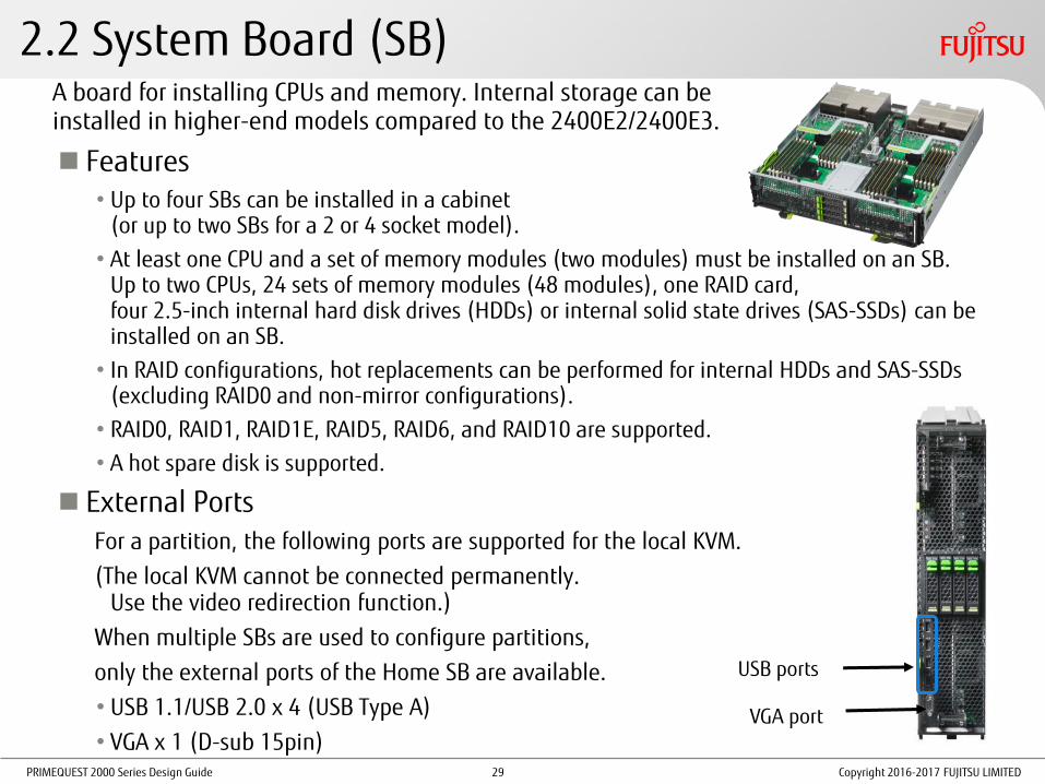
A board for installing CPUs and memory. Internal storage can be installed in higher-end models compared to the 2400E2/2400E3.
Features •Up to four SBs can be installed in a cabinet
(or up to two SBs for a 2 or 4 socket model).
• At least one CPU and a set of memory modules (two modules) must be installed on an SB. Up to two CPUs, 24 sets of memory modules (48 modules), one RAID card, four 2.5-inch internal hard disk drives (HDDs) or internal solid state drives (SAS-SSDs) can be installed on an SB.
• In RAID configurations, hot replacements can be performed for internal HDDs and SAS-SSDs (excluding RAID0 and non-mirror configurations).
• RAID0, RAID1, RAID1E, RAID5, RAID6, and RAID10 are supported.
• A hot spare disk is supported.
External Ports For a partition, the following ports are supported for the local KVM.
(The local KVM cannot be connected permanently. Use the video redirection function.)
When multiple SBs are used to configure partitions,
only the external ports of the Home SB are available.
•USB 1.1/USB 2.0 x 4 (USB Type A)
•VGA x 1 (D-sub 15pin)
2.2 System Board (SB)
VGA port
USB ports
Copyright 2016-2017 FUJITSU LIMITED 29

PRIMEQUEST 2000 Series Design Guide
2.2.1 CPU (1/5) Intel® Xeon® processors are used.
A QPI interface and memory controllers are integrated in these processors.
It is possible to scale up the configuration by connecting CPUs via the QPI.
Copyright 2016-2017 FUJITSU LIMITED
CPUs Supported by the PRIMEQUEST 2000 Series (1)
Product number Performance Number of cores 2800B2 2400E2 2800E2
Intel® Xeon® Processor E7-8890v3 2.50GHz/45.0MB 18 Yes Yes Yes
Intel® Xeon® Processor E7-8880v3 2.30GHz/45.0MB 18 Yes Yes Yes
Intel® Xeon® Processor E7-8870v3 2.10GHz/45.0MB 18 Yes Yes Yes
Intel® Xeon® Processor E7-8867v3 2.50GHz/45.0MB 16 Yes Yes Yes
Intel® Xeon® Processor E7-8860v3 2.20GHz/40.0MB 16 Yes Yes Yes
Intel® Xeon® Processor E7-8891v3 2.80GHz/45.0MB 10 Yes Yes Yes
Intel® Xeon® Processor E7-8893v3 3.20GHz/45.0MB 4 Yes Yes Yes
Yes: Installable -: Not installable
Note: For the latest information on the supported CPUs, contact your sales representative. The CPUs that can be installed vary between models. The CPUs listed in table (1) and table (2) cannot be mixed. To use Memory Scale-up Boards, two CPUs must be installed in the system board of the connection destination. However, connections to Memory Scale-up Boards are not available if the Intel® Xeon® Processor E7-8860v3 is installed in the system board.
30
PRIMEQUEST 2000 Series Design Guide
2.2.1 CPU (2/5)
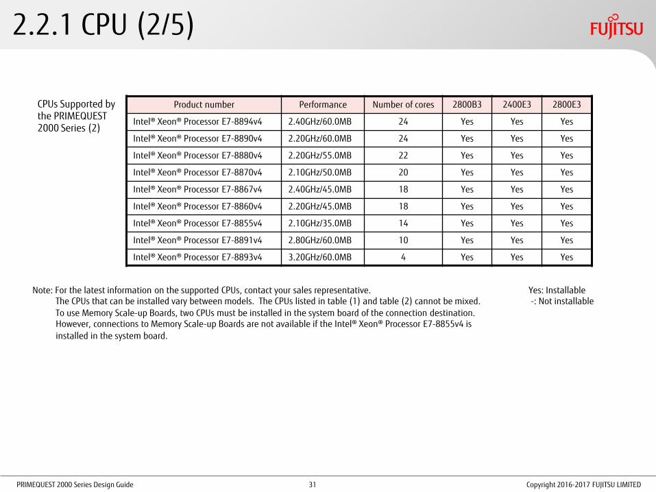
CPUs Supported by the PRIMEQUEST 2000 Series (2)
Yes: Installable -: Not installable
Note: For the latest information on the supported CPUs, contact your sales representative. The CPUs that can be installed vary between models. The CPUs listed in table (1) and table (2) cannot be mixed. To use Memory Scale-up Boards, two CPUs must be installed in the system board of the connection destination. However, connections to Memory Scale-up Boards are not available if the Intel® Xeon® Processor E7-8855v4 is installed in the system board.
Copyright 2016-2017 FUJITSU LIMITED
Product number Performance Number of cores 2800B3 2400E3 2800E3
Intel® Xeon® Processor E7-8894v4 2.40GHz/60.0MB 24 Yes Yes Yes
Intel® Xeon® Processor E7-8890v4 2.20GHz/60.0MB 24 Yes Yes Yes
Intel® Xeon® Processor E7-8880v4 2.20GHz/55.0MB 22 Yes Yes Yes
Intel® Xeon® Processor E7-8870v4 2.10GHz/50.0MB 20 Yes Yes Yes
Intel® Xeon® Processor E7-8867v4 2.40GHz/45.0MB 18 Yes Yes Yes
Intel® Xeon® Processor E7-8860v4 2.20GHz/45.0MB 18 Yes Yes Yes
Intel® Xeon® Processor E7-8855v4 2.10GHz/35.0MB 14 Yes Yes Yes
Intel® Xeon® Processor E7-8891v4 2.80GHz/60.0MB 10 Yes Yes Yes
Intel® Xeon® Processor E7-8893v4 3.20GHz/60.0MB 4 Yes Yes Yes
31

PRIMEQUEST 2000 Series Design Guide
2.2.1 CPU (3/5)
QuickPath Interconnect (QPI)
•A high-speed system bus delivering up to 9.6GT/s (bandwidth 38.4GB/s)
•The QPI connects a CPU and a chipset or connects CPUs to each other.
CPU Installation Conditions
For details, refer to "Appendix G Component Mounting Conditions" in "Administration Manual".
•CPUs must be installed from CPU#0 on an SB in the order of the slot numbers.
•SBs in which no CPU is installed cannot be incorporated in a PPAR block.
•At least one set of memory modules (two modules) must be installed for a CPU.
Conditions for Installing Different CPUs
Different types of CPUs can be installed in different PPAR blocks. (The CPUs must be supported in the PRIMEQUEST model.)
Copyright 2016-2017 FUJITSU LIMITED 32

PRIMEQUEST 2000 Series Design Guide
2.2.1 CPU (4/5)
Conditions for Installing Different CPUs (1/2)
IOU#0 IOU#1
Flexible I/O
SB#0 SB#1
IOU#0 IOU#1
Flexible I/O
SB#0 SB#1 Different CPUs
cannot be installed in the
same PPAR block.
Different CPUs can be installed in different PPAR blocks.
Different types of CPUs can be installed in different PPAR blocks of a cabinet (*).
Partition#0 Partition#0 Partition#1
(*) The CPUs must be supported in the PRIMEQUEST model.
Copyright 2016-2017 FUJITSU LIMITED
CPU
A CPU
A CPU
B
CPU
A CPU
A CPU
B CPU
B CPU
B
33

PRIMEQUEST 2000 Series Design Guide
2.2.1 CPU (5/5) Conditions for Installing Different CPUs (2/2)
Different types of CPUs cannot be installed in the same PPAR block.
Different types of CPUs cannot be installed in the same PPAR block of a cabinet.
IOU#0
Flexible I/O
Partition#0
SB#0
IOU#0
Partition#0 Partition#1
IOU#1
Flexible I/O
SB#0 SB#1
This installation is not allowed because PPAR#0 is switched from SB#0 to SB#2 if a failure occurs in SB#0.
Copyright 2016-2017 FUJITSU LIMITED
CPU
B CPU
B CPU
A CPU
A
IOU#0
Flexible I/O
Partition#0
Reserved SB
SB#0
CPU
A CPU
A
SB#1 SB#2
CPU
A CPU
A CPU
B CPU
B
IOU#0
Flexible I/O
SB#0
CPU
A CPU
A
SB#1 SB#2
CPU
A CPU
A
Partition#0 Reserved SB
CPU
A CPU
A
34

PRIMEQUEST 2000 Series Design Guide
2.2.2 Memory (1/7) Supported memory types are 8GB, 16GB, 32GB, 64GB, and 128GB DDR3/DDR4 DIMM.
Install a set of two identical DIMMs.
• Install four DIMMs (two sets) to use the Memory Mirror function. (Refer to "2.2.2 Memory (4/7)".)
• Install six DIMMs (three sets) to use the Memory Spare function. (Refer to "2.2.2 Memory (4/7)".)
• Refer to "2.2.2 Memory (5/7)" to use the Dynamic Reconfiguration function in either of the following conditions:
- When one partition is configured with a total of four boards that consist of system boards and Memory Scale-up boards.
- When one PPAR block is configured with eight CPUs and the Segment Mode (*1) is set as the PCI Address mode.
For one CPU, six sets of memory modules can be installed in the memory slots on the SB and another six sets of memory modules can be installed on an optional extended memory board.
Installed memory operates only when the relevant CPU is operating. Installation Group
Install memory modules in pairs where the memory slot numbers third digit has a difference of 3.
128GB DIMMs are supported only AC 200V environment.
Installation Group (1 CPU and Normal Mode)
Installation group Memory slot numbers
1 0A0, 0A3
2 0A1, 0A4
3 0A2, 0A5
4 0B0, 0B3
5 0B1, 0B4
6 0B2, 0B5
: :
24 1D2, 1D5
Memory Slot Arrangement
: Memory slots on an extended memory board
Copyright 2016-2017 FUJITSU LIMITED
(*1) Segment Mode: A "PCI Address Mode" that uses Seg/Bus/Dev/Func (default) to configure a type of PCI space in a partition. Segment Mode allows the use of more I/O than "Bus Mode".
35

PRIMEQUEST 2000 Series Design Guide
2.2.2 Memory (2/7)
Memory Installation Conditions • For one CPU, 1 to 12 sets of memory modules can be installed.
• Memory must be added on a set basis. (Add memory on a two-set basis when the Memory Mirror function is used or on a three-set basis when the Memory Spare function is used.) When only one set of memory module is installed, if one module fails, the SB is disconnected from the PPAR block. Therefore, it is recommended to install at least two sets of memory modules.
• Only the same memory modules can be installed to the same memory channel of each Memory Buffer. Different memory modules can be installed for different memory channels.
• When the Memory Mirror function is used, install the same configuration of memory (in size and the number of modules) in multiple memory channels that are used for mirroring.
• When the Memory Spare function is used, install the same memory modules in all six slots of the same Memory Buffer.
A "memory channel" is a DDR3/DDR4 interface connected to a Memory Buffer.
"Same memory channel" The same memory modules
must be installed. * MB: Memory Buffer
"Same memory channel" The same memory modules
must be installed.
Copyright 2016-2017 FUJITSU LIMITED 36

PRIMEQUEST 2000 Series Design Guide Copyright 2016-2017 FUJITSU LIMITED
2.2.2 Memory (3/7) Memory Installation Order
• When installing memory modules in the memory slots whose slot numbers have the same first and second digits, install the modules in the order of the third digit pairs, i.e., (0 and 3), (1 and 4), and (2 and 5).
Refer to the table in the following "Example of Installation Order".
• There are multiple patterns in installation order depending on whether the Memory Mirror function or Memory Spare function is used or not.
For details on installation order, refer to "G.2.1 DIMM mounting order and DIMM mixed mounting condition" in "Administration Manual" and the following slides.
[Example of Installation Order] 1 CPU and Normal Mode (The Same Type of Memory is Shown in the Same Color.)
CPU# MB# Memory
slot# Installation
order
0
D
0D5 12 0D4 8 0D3 4 0D2 12 0D1 8 0D0 4
C
0C5 10 0C4 6 0C3 2 0C2 10 0C1 6 0C0 2
B
0B5 11 0B4 7 0B3 3 0B2 11 0B1 7 0B0 3
A
0A5 9 0A4 5 0A3 1 0A2 9 0A1 5 0A0 1
37

PRIMEQUEST 2000 Series Design Guide
2.2.2 Memory (4/7)
•DIMM installation order for each mode
Copyright 2016-2017 FUJITSU LIMITED
(Slots with the same symbols must have the same type of DIMM installed.) • Install DIMMs at the same time in the slots with the same installation order number.
• When only one CPU is installed, install the DIMMs in the slots starting from the smallest slot number on CPU#0. • DIMMs are available in sets of two.
Refer to the next slide to use the Dynamic Reconfiguration function in either of the following conditions: - When one partition is configured with a total of four boards that consist of system boards and Memory Scale-up boards. - When one PPAR block is configured with eight CPUs (Segment Mode).
CPU#0 CPU#1
Slot No.
0A0 0A3 0B0 0B3 0C0 0C3 0D0 0C3 1A0 1A3 1B0 1B3 1C0 1C3 1D0 1D3
0A1 0A4 0B1 0B4 0C1 0C4 0D1 0C4 1A1 1A4 1B1 1B4 1C1 1C4 1D1 1D4
0A2 0A5 0B2 0B5 0C2 0C5 0D2 0C5 1A2 1A5 1B2 1B5 1C2 1C5 1D2 1D5
Normal Mode
1 1 4 4 2 2 6 6 1 1 5 5 3 3 7 7
8 8 12 12 10 10 14 14 9 9 13 13 11 11 15 15
16 16 20 20 18 18 22 22 17 17 21 21 19 19 23 23
Mirror Mode
1 1 1 1 2 2 2 2 1 1 1 1 3 3 3 3
4 4 4 4 6 6 6 6 5 5 5 5 7 7 7 7
8 8 8 8 10 10 10 10 9 9 9 9 11 11 11 11
Spare Mode
1 1 4 4 2 2 6 6 1 1 5 5 3 3 7 7
1 1 4 4 2 2 6 6 1 1 5 5 3 3 7 7
1 1 4 4 2 2 6 6 1 1 5 5 3 3 7 7
38

PRIMEQUEST 2000 Series Design Guide
2.2.2 Memory (5/7)
Copyright 2016-2017 FUJITSU LIMITED
(Slots with the same symbols must have the same type of DIMM installed.)
• DIMM installation order for each mode (when one of the following conditions apply)
• Dynamic Reconfiguration is used
• One partition is configured with four boards that are a combination of system boards and Memory Scale-up Boards
• One PPAR block is configured with eight CPUs when the Segment Mode is set as the PCI Address mode
• Install DIMMs at the same time in the slots with the same installation order number. • When Dynamic Reconfiguration is used or one PPAR block is configured with eight CPUs, two CPUs are installed in an SB. • When only one CPU is installed and Dynamic Reconfiguration is enabled, IOU- Dynamic Reconfiguration requires memory installation for CPU#0 in the above order. • DIMMs are available in sets of two.
CPU#0 CPU#1
Slot No.
0A0 0A3 0B0 0B3 0C0 0C3 0D0 0C3 1A0 1A3 1B0 1B3 1C0 1C3 1D0 1D3
0A1 0A4 0B1 0B4 0C1 0C4 0D1 0C4 1A1 1A4 1B1 1B4 1C1 1C4 1D1 1D4
0A2 0A5 0B2 0B5 0C2 0C5 0D2 0C5 1A2 1A5 1B2 1B5 1C2 1C5 1D2 1D5
Normal Mode
1 1 2 2 1 1 2 2 1 1 2 2 1 1 2 2
3 3 4 4 3 3 4 4 3 3 4 4 3 3 4 4
5 5 6 6 5 5 6 6 5 5 6 6 5 5 6 6
Mirror Mode
1 1 1 1 1 1 1 1 1 1 1 1 1 1 1 1
2 2 2 2 2 2 2 2 2 2 2 2 2 2 2 2
3 3 3 3 3 3 3 3 3 3 3 3 3 3 3 3
Spare Mode
1 1 2 2 1 1 2 2 1 1 2 2 1 1 2 2
1 1 2 2 1 1 2 2 1 1 2 2 1 1 2 2
1 1 2 2 1 1 2 2 1 1 2 2 1 1 2 2
39

PRIMEQUEST 2000 Series Design Guide
2.2.2 Memory (6/7) Conditions of Installing Different Memory Modules
16GB memory (8GB single-rank (*1) DIMM x 2) and 32GB memory (16GB dual-rank (*1) DIMM x 2) can be installed in the same partition. Different types of memory modules other than the above combination cannot be installed together in the same partition. Different types of memory modules can be installed in a different partition on a different SB.
Partition#0 Partition#1 Partition#0
16GB (8GB DIMM x 2)
64GB (32GB DIMM x 2)
16GB (8GB DIMM x 2)
32GB (16GB DIMM x 2)
64GB (32GB DIMM x 2)
Copyright 2016-2017 FUJITSU LIMITED
(*1) Memory rank: A unit of data input and output by a memory controller from the DRAM chips on a DIMM Memory access performance increases as the rank number increases.
40

PRIMEQUEST 2000 Series Design Guide
2.2.2 Memory (7/7)
Memory Mirror •Mirroring is performed between the memory group in MB#xA and MB#xB and the memory
group in MB#xC and MB#xD that are controlled by the same CPU.
•Memory Mirror is available even if only one CPU is installed in an SB.
Memory Spare •When multiple DIMM pairs are configured, a DIMM rank is used as a spare of other ranks.
• If the number of correctable errors that occur in a specific time period in a rank exceeds a threshold, the contents of the memory are copied to the rank that has been reserved as a spare and the DIMM rank in which the errors occurred is disconnected.
* Memory Mirror and Memory Spare cannot be enabled at the same time.
Memory Spare Memory Mirror Mirroring is available only between the same types of memory.
Intra-CPU mirroring
DIMM pair
Dual rank Spare
DIMM pair DIMM pair
Rank 0 Rank 0
DIMM pair
Single rank Spare Rank 0 Rank 0 Rank 0 Rank 0
DIMM pair DIMM pair
DIMM A DIMM B DIMM C DIMM D DIMM E DIMM F
* The available memory capacity is two-thirds of the total capacity of the installed memory.
* The available memory capacity is five-sixths of the total capacity of the installed memory.
Rank 0 Rank 0 Rank 0 Rank 0
Rank 1 Rank 1 Rank 1 Rank 1 Rank 1 Rank 1
DIMM A DIMM B DIMM C DIMM D DIMM E DIMM F
Rank 0 Rank 0
Copyright 2016-2017 FUJITSU LIMITED 41

PRIMEQUEST 2000 Series Design Guide
2.2.3 Memory Scale-up Board
Copyright 2016-2017 FUJITSU LIMITED
Memory installation boards only for the 2400E2/2400E3
Features • Up to three Memory Scale-up Boards can be installed in a cabinet.
• At least four sets of memory modules (eight modules) must be installed in a Memory Scale-up Board. A maximum of 24 sets of memory modules (48 modules) can be installed in a Memory Scale-up Board.
Memory Installation Conditions • Same as the system board (except 128GB DIMMs cannot be installed)
(For details, refer to "2.2.2 Memory (2/7)".)
Notes • To use Memory Scale-up Boards, two CPUs must be installed
in the system board of the connection destination. However, connections to Memory Scale-up Boards are not available if the Intel® Xeon® Processor E7-8860v3 or the Intel® Xeon® Processor E7-8855v4 is installed in the system board.
• SBs can be specified as Reserved SBs even if the partitions also include Memory Scale-up Boards. Memory Scale-up Boards do not support spare switching similar to Reserved SBs.
* Memory Scale-up Boards support the degradation function.
• The supported OSs are RHEL6 and RHEL7 only. Windows Server, SLES, Oracle Linux, Oracle VM and VMware are not supported.
42

PRIMEQUEST 2000 Series Design Guide
2.3 Management Board (MMB) (1/3)
A system control board that is equipped with an independent dedicated processor Features
•Redundant configuration can be achieved by installing two boards.
•Hot swap is possible only in a redundant configuration. •The dedicated CPU operates as a dedicated host for system management. •A Web server that is included in an MMB provides a graphical user
interface. •An MMB can be operated from a Web browser (GUI) on a remote PC, and it
is not necessary to prepare an operation management server separately. •Hardware management and monitoring function •Consolidated management and monitoring of the power supply, fan, and
hardware of each partition •Hardware setup (configuration change) function •Power control in the cabinet, sensor monitoring, partition configuration
settings, Memory Mirror mode settings, and reset process •Collection and display of operation logs and error logs
Copyright 2016-2017 FUJITSU LIMITED 43

PRIMEQUEST 2000 Series Design Guide
2.3 Management Board (MMB) (2/3)
•High-Level Security
•An original protocol is used to perform internal communication.
•Server management interfaces (Web Server and SNMP) are managed collectively.
•It is possible to add user definitions that allow operating only specific partitions. This function prevents wrong operations and malicious operations on partitions.
MMB (One board is included in the default configuration. Another MMB can be added for redundancy.)
SB (Partition)
SB (Partition)
Management and monitoring
Copyright 2016-2017 FUJITSU LIMITED 44

PRIMEQUEST 2000 Series Design Guide
2.3 Management Board (MMB) (3/3)
External Ports •User port x 2
Used to connect to the management LAN for operation management of PRIMEQUEST.
Duplication is possible.
•Port for maintenance x 1
Used by field engineers for maintenance.
•COM port for an MMB console
Used for initial setting.
User ports Port for maintenance
COM port for an MMB console
Copyright 2016-2017 FUJITSU LIMITED 45

PRIMEQUEST 2000 Series Design Guide
2.4 IO Unit (IOU) (1/3)
A unit that is equipped with PCI Express slots and LAN ports
There are two types of IOUs: 1GbE and 10GbE. Features
•An IOU connects components and external devices to an SB.
•Up to four IOUs can be installed in a cabinet.
•The number of PCI Express slots that can be installed in each IOU is as follows: - 1GbE IO unit : 4 - 10GbE IO unit : 3
•To connect a PCI Box, install a PCI Box connection card in the specified PCI Express slot on the IOU.
•1GbE IO units and 10GbE IO units can be installed together in the same cabinet.
Copyright 2016-2017 FUJITSU LIMITED 46

PRIMEQUEST 2000 Series Design Guide
2.4 IO Unit (IOU) (2/3)
1GbE IO Unit
•A 1GbE IO unit has two 1000BASE-T LAN ports.
•Up to four PCI cards with low profile bracket sizes can be installed.
10GbE IO Unit
•A 10GbE IO unit has two 10GBASE-T LAN ports.
•Up to three PCI cards can be installed. (If the bracket size of the PCI card is full height, up to two cards can be installed.)
1GbE IO Unit 10GbE IO Unit
Copyright 2016-2017 FUJITSU LIMITED 47

PRIMEQUEST 2000 Series Design Guide
2.4 IO Unit (IOU) (3/3)
IOU Configuration Examples
[Example with FC Cards] Connection to an external storage device (ETERNUS)
[Example with LAN Cards] Addition of LAN ports in a cluster configuration
[Example with a SAS Array Controller Card] Connection to an external hard disk cabinet (JX40 S2)
[Example with a SAS Card] Connection to a backup cabinet (PRIMERGY SX05)
PRIMERGY SX05
ETERNUS
JX40 S2
Copyright 2016-2017 FUJITSU LIMITED 48
PRIMEQUEST 2000 Series Design Guide
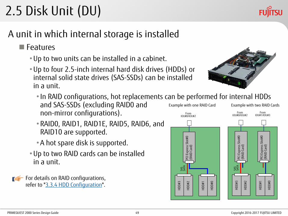
2.5 Disk Unit (DU)
A unit in which internal storage is installed Features
•Up to two units can be installed in a cabinet.
•Up to four 2.5-inch internal hard disk drives (HDDs) or internal solid state drives (SAS-SSDs) can be installed in a unit.
•In RAID configurations, hot replacements can be performed for internal HDDs and SAS-SSDs (excluding RAID0 and non-mirror configurations).
•RAID0, RAID1, RAID1E, RAID5, RAID6, and RAID10 are supported.
•A hot spare disk is supported.
•Up to two RAID cards can be installed in a unit. P
CI E
xpre
ss S
lot#
0 (
RA
ID C
ard)
HD
D#3
HD
D#2
HD
D#1
HD
D#0
SAS
SATA
From IOU#0/IOU#2
For details on RAID configurations, refer to "3.3.4 HDD Configuration".
Example with one RAID Card Example with two RAID Cards
PCI
Exp
ress
Slo
t#0
(R
AID
Car
d)
HD
D#3
HD
D#2
HD
D#1
HD
D#0
SAS
SATA
From IOU#0/IOU#2
PCI
Exp
ress
Slo
t#0
(R
AID
Car
d)
From IOU#1/IOU#3
Copyright 2016-2017 FUJITSU LIMITED 49

PRIMEQUEST 2000 Series Design Guide
2.6 PCI Box (1/4)
An extended I/O cabinet that is equipped with 12 PCI Express slots, each having eight PCI Express Gen3 (8Gbps) lanes Features
• Up to four PCI Boxes can be connected to a cabinet.
(No PCI Box can be connected to 2800B2/2800B3.)
• The PCI Box connection card on an IOU is used to connect a PCI Box.
• PCI Hot Plug (PHP) for PCI Express cards is supported.
• A PCI Box can be divided into two partitions (PCI Box LH modules), each having six slots.
• PCI Boxes, power supply units and power cables for PCI Boxes need to be obtained separately.
PHP
PCI Box LH
PCI Box LH
For details on the power supply configuration for a PCI Box, refer to "3.5.1 Power Supply Redundancy".
IOU connection port Six PCI Express
(eight lanes) slots
Copyright 2016-2017 FUJITSU LIMITED
PEXU: PCI Express Unit
LNKC: LINK Card. These cards are installed in PCI Boxes and are used to connect to IOUs.
The PHP function is not available when Oracle Linux and virtualization
software are used.
50
PRIMEQUEST 2000 Series Design Guide
2.6 PCI Box (2/4)
Copyright 2016-2017 FUJITSU LIMITED
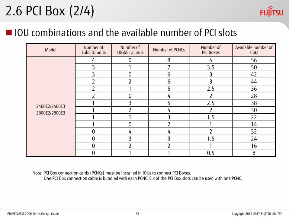
IOU combinations and the available number of PCI slots
Model Number of
1GbE IO units Number of
10GbE IO units Number of PCNCs
Number of PCI Boxes
Available number of slots
2400E2/2400E3
2800E2/2800E3
4 0 8 4 56 3 1 7 3.5 50 3 0 6 3 42 2 2 6 3 44 2 1 5 2.5 36 2 0 4 2 28 1 3 5 2.5 38 1 2 4 2 30 1 1 3 1.5 22 1 0 2 1 14 0 4 4 2 32 0 3 3 1.5 24 0 2 2 1 16 0 1 1 0.5 8
Note: PCI Box connection cards (PCNCs) must be installed in IOUs to connect PCI Boxes. One PCI Box connection cable is bundled with each PCNC. Six of the PCI Box slots can be used with one PCNC.
51

PRIMEQUEST 2000 Series Design Guide
2.6 PCI Box (3/4)
PCI Box Connection Conditions Different cabinets cannot be connected to a PCI Box (PCI Boxes cannot be shared by servers).
Straight Connection Cross Connection
Connection to Different PCI Boxes Connection from Different Cabinets to a PCI Box
Connection from 1GbE IO Units and 10GbE IO Units
Copyright 2016-2017 FUJITSU LIMITED
* The connection configuration depends on the type of IO unit that is to be installed.
52

PRIMEQUEST 2000 Series Design Guide
2.6 PCI Box (4/4)
A Configuration for Redundancy of PCI Boxes and PCI Box LH modules
The effects of a failed PCI Box are taken into account.
A Configuration for Failure Isolation of PCI Boxes
SB IOU
Partition#0
SB
Partition#1
PRIMEQUEST
IOU
Advantage Even if one PCI Box fails, the failed PCI Box can be disconnected by a reboot and the system can be started using the other PCI Box. Disadvantage Both partitions stop when a PCI Box fails.
PCI Box LH #0
PCI Box #0 PCI Box LH #1 PCI Box LH #0
PCI Box #1
SB IOU
Partition#0
SB
Partition#1
PRIMEQUEST
IOU
PCI Box #0 PCI Box #1
Stop
Redundancy of the PCI Boxes and PCI Box LH modules
The PCI Box is disconnected by a reboot.
Not affected
The PCI Box cannot be used until it is repaired.
The failure in partition#1 is isolated from partition#0.
PCI Box LH #1 PCI Box LH #0 PCI Box LH #1 PCI Box LH #0
For details on redundancy of PCI Express cards and connection destinations, refer to "3.3.5 Network Configuration".
Failure
Failure
Stop Start in a
degraded state
Start in a degraded state
Stop
Advantage This configuration provides failure isolation. Even if the PCI Box for a partition fails, the other partition is not affected. Disadvantage The PCI Box for the relevant partition cannot be used until the PCI Box is repaired.
Copyright 2016-2017 FUJITSU LIMITED
PCI Box LH #1
53

PRIMEQUEST 2000 Series Design Guide
2.7 Internal SSD (Limited Service Life Component)
Copyright 2016-2017 FUJITSU LIMITED
Solid State Drives Installed in IOUs or PCI Boxes Limited Number of Write Operations "Limited service life components" include the NAND flash memory which has a limited
number of write operations Depending on how SSDs are used, the NAND flash memory may reach the predetermined number of write operations before the product warranty period expires.
Warranty period The product warranty period ends when the warranty period expires or when the product reaches the guaranteed predetermined write value, whichever comes first.
Checking the status of the allowed write value, etc. • The status can be checked with management software or with command line tools. • Estimate the amount of writes when designing the system. In addition, check the status regularly
after system implementation. • If there is a possibility that the guaranteed predetermined write value is reached before the
system reaches the end of its service life, spare parts and procedures for moving the data to the spare parts must be prepared.
DWPD (Drive Writes Per Day): The average number of overwrite operations that can be performed in one day with the amount of data equivalent to the entire drive
Product name Product ID Guaranteed write value
DWPD
800GB PCIe SSD MC-0JSD61 / MCX0JSD61
10 times 1.6TB PCIe SSD MC-0JSD71 / MCX0JSD71
2TB PCIe SSD MC-0JSD81 / MCX0JSD81
54

PRIMEQUEST 2000 Series Design Guide
2.8 Power Supply Unit (PSU) A power supply unit (with FANs installed) that converts AC200V or AC100V to DC12V
For details on connecting this unit, refer to "2.3 Power cable connection" in "Hardware Installation Manual".
Up to six PSUs can be installed in a cabinet. For details on the number of PSUs that must be installed, refer to "4.5.1 PSU Configuration" in "General Description".
The following three types of units are available (but cannot be installed together).
• High-efficiency power supply unit (200V): 80 PLUS® Platinum certified • Power supply unit (200V): Equivalent to an 80 PLUS® Silver • Power supply unit (100V): Equivalent to an 80 PLUS® Silver
(2800B2/2800B3/2800E2/2800E3 does not support 100V.)
Power Supply Configuration
Input voltage
Power feeding method
Redundancy 2400E2/2400E3 2400E2/2400E3
with Memory Scale-up Board
2800B2/2800B3 2800E2/2800E3
200V Single power feed
Non-redundant 2 (2 + 0) 3 (3 + 0) 3 (3 + 0)
Redundant 3 (2 + 1) 4 (3 + 1) 4 (3 + 1)
Dual power feed Redundant 4 (2 x 2) 6 (3 x 2) 6 (3 x 2)
100V Single power feed
Non-redundant 4 (4 + 0)
Not supported Not supported Redundant 5 (4 + 1)
Redundant (for redundant UPS systems)
6 (4 + 2)
Dual power feed Not supported
Copyright 2016-2017 FUJITSU LIMITED 55

PRIMEQUEST 2000 Series Design Guide
2.9 FAN Unit (FANU)
A unit that contains only a FAN and can be installed in a PSU slot in which no PSU is installed.
A total of six units between the PSUs and the FANUs must be installed.
For details on the number of FANUs that must be installed and the installation slots, refer to "4.5.1 PSU Configuration" in "General Description".
Copyright 2016-2017 FUJITSU LIMITED
A total of six units between the PSUs and the FANUs are installed.
56

PRIMEQUEST 2000 Series Design Guide
2.10 Peripheral Configuration (1/4)
Console Unit
A PC is required to connect a console.
For details, refer to "4.1 Key Points for Console Operation".
Copyright 2016-2017 FUJITSU LIMITED 57
PRIMEQUEST 2000 Series Design Guide
2.10 Peripheral Configuration (2/4) Rack
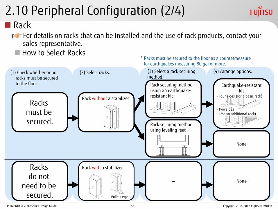
For details on racks that can be installed and the use of rack products, contact your sales representative.
How to Select Racks
(1) Check whether or not racks must be secured to the floor.
(2) Select racks. (3) Select a rack securing method.
(4) Arrange options.
Racks must be secured.
Rack securing method using an earthquake-resistant kit
Rack securing method using leveling feet
None
Earthquake-resistant kit
Rack without a stabilizer
Racks do not
need to be secured.
Rack with a stabilizer
- None
* Racks must be secured to the floor as a countermeasure for earthquakes measuring 80 gal or more.
- Two sides (for an additional rack)
- Four sides (for a basic rack)
Pullout type
Copyright 2016-2017 FUJITSU LIMITED 58

PRIMEQUEST 2000 Series Design Guide
2.10 Peripheral Configuration (3/4)
Notes on Using Racks •When installing devices in a rack, install heavier devices on the bottom to
lower the center of gravity and stabilize the rack.
•Attach a blank panel to the front of each unused space of the rack.
PRIMERGY and ETERNUS can also be installed.
PRIMERGY
ETERNUS
Rack External View For PRIMEQUEST, it is recommended that one PRIMEQUEST unit is installed per rack. (In some cases, two units can be installed.)
x 1 unit (recommended)
PRIMEQUEST
Copyright 2016-2017 FUJITSU LIMITED 59

PRIMEQUEST 2000 Series Design Guide
2.10 Peripheral Configuration (4/4)
Rack Installation Requirements A. Allowable spacing between posts: 685 to 790mm
B. Distance from the inside of the front door to the outside of the front rack posts: 60mm or more
C. Distance from the outside of the front rack posts to the inside of the rear door: 860mm or more
For details on rack installation conditions, refer to "Hardware Installation Manual".
A
B C
Rear door Front door
Front
Posts
Posts
Copyright 2016-2017 FUJITSU LIMITED 60

PRIMEQUEST 2000 Series Design Guide Copyright 2016-2017 FUJITSU LIMITED
3. Hardware Configuration Design
This chapter describes the key points for designing hardware configurations.
61

PRIMEQUEST 2000 Series Design Guide
3.1 Key Points for MMB Design
When focusing on reliability, install two MMBs to create a redundant configuration
Considerations Before Setting an MMB IP address, host name, subnet mask, and gateway address
User accounts
Name of the PRIMEQUEST system (this is also used as the SNMP system name.)
Management VLAN (virtual IP addresses, etc.) environment
Copyright 2016-2017 FUJITSU LIMITED
For details, refer to "2.2 Key Points for the MMB Settings" in "Linux (RHEL) Installation Guide" and "3.3 Connection and Setting of MMB" in "Installation Manual".
62

PRIMEQUEST 2000 Series Design Guide
3.2 Key Points for Hardware Partitioning Design
Key Points for Configuring PPAR blocks
Partitioning Design Rules For details, refer to "3.2.1 Partitioning Design Rules".
Key points for partitioning design
Partition granularity and configuration conditions
The total numbers of system boards/Memory Scale-up Boards and CPUs per partition
Functions That are Used for Partition Configuration For details, refer to "3.2.2 Functions That are Used for Partition Configuration".
Home SB
Reserved SB function
Dynamic Reconfiguration function
Switching Reserved SB Rules For details, refer to "3.2.3 Switching Reserved SB Rules".
Configuration Example For details, refer to "3.2.4 Configuration Example".
Guidelines for selecting a partition configuration
Configuration examples for each model Copyright 2016-2017 FUJITSU LIMITED 63
PRIMEQUEST 2000 Series Design Guide
3.2.1 Partitioning Design Rules (1/2)
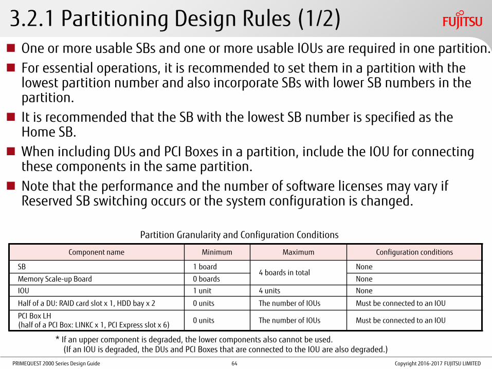
Component name Minimum Maximum Configuration conditions
SB 1 board 4 boards in total
None
Memory Scale-up Board 0 boards None
IOU 1 unit 4 units None
Half of a DU: RAID card slot x 1, HDD bay x 2 0 units The number of IOUs Must be connected to an IOU
PCI Box LH (half of a PCI Box: LINKC x 1, PCI Express slot x 6)
0 units The number of IOUs Must be connected to an IOU
One or more usable SBs and one or more usable IOUs are required in one partition.
For essential operations, it is recommended to set them in a partition with the lowest partition number and also incorporate SBs with lower SB numbers in the partition.
It is recommended that the SB with the lowest SB number is specified as the Home SB.
When including DUs and PCI Boxes in a partition, include the IOU for connecting these components in the same partition.
Note that the performance and the number of software licenses may vary if Reserved SB switching occurs or the system configuration is changed.
Partition Granularity and Configuration Conditions
* If an upper component is degraded, the lower components also cannot be used. (If an IOU is degraded, the DUs and PCI Boxes that are connected to the IOU are also degraded.)
Copyright 2016-2017 FUJITSU LIMITED 64

PRIMEQUEST 2000 Series Design Guide
3.2.1 Partitioning Design Rules (2/2)
Partition configuration
(Number of SBs per partition)
Total number of CPUs
2800B2/2800B3 2400E2/2400E3 2400E2/2400E3 with
Memory Scale-up Board 2800E2/2800E3
One SB
1 - Yes - Yes
2 Yes Yes Yes
(up to three Memory Scale-up Boards)
Yes
Two SBs
2 - Yes - -
3 - - - -
4 Yes Yes Yes
(up to two Memory Scale-up Boards)
Yes
Three SBs 6 Yes - - Yes
Four SBs 8 Yes - - Yes
The Total Numbers of System Boards/Memory Scale-up Boards and CPUs per Partition When multiple SBs are used to configure a partition:
• For the 2800B2/2800B3/2800E2/2800E3, two CPUs must be installed in each SB.
• For the 2400E2/2400E3, the same number of CPUs must be installed between the SBs.
When 128GB DIMMs are used, a single partition can only be configured with one SB. A single partition cannot be configured with multiple SBs.
In a default configuration, an SB with two CPUs and an SB with one CPU in one partition (2SB-3CPU) cannot be installed.
Yes: Possible -: Not possible
Copyright 2016-2017 FUJITSU LIMITED 65

PRIMEQUEST 2000 Series Design Guide
3.2.2 Functions That are Used for Partition Configuration - Home SB
Home SB The main SB among the SBs that are used to configure a PPAR block.
Functions That Are Enabled on the Home SB
•PCH (*1)
Onboard I/O is enabled, and USB ports and a VGA port can be used only on the Home SB.
•Reference clock source
The clock source of the Home SB becomes the clock source in the partition.
Selection of the Home SB
Specify the Home SB by using the MMB Web-UI.
If the Home SB is not specified directly, the first SB that is incorporated in the partition is specified as the Home SB.
* If the Home SB is removed from the partition or is degraded, the SB with the lowest number in the partition is specified as the Home SB.
Copyright 2016-2017 FUJITSU LIMITED
(*1) PCH: An Intel C600 series with built-in controllers such as USB controllers, APIC, and RTC
66
PRIMEQUEST 2000 Series Design Guide
SB#0 SB#1 SB#2 SB#3
IOU#0 IOU#1 IOU#2 IOU#3
SB#0 SB#1 SB#2 SB#3
IOU#0 IOU#1 IOU#2 IOU#3
3.2.2 Functions That are Used for Partition Configuration - Reserved SB (1/6)
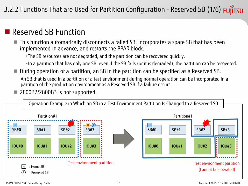
Reserved SB Function This function automatically disconnects a failed SB, incorporates a spare SB that has been
implemented in advance, and restarts the PPAR block.
•The SB resources are not degraded, and the partition can be recovered quickly.
•In a partition that has only one SB, even if the SB fails (or it is degraded), the partition can be recovered.
During operation of a partition, an SB in the partition can be specified as a Reserved SB.
An SB that is used in a partition of a test environment during normal operation can be incorporated in a partition of the production environment as a Reserved SB if a failure occurs.
2800B2/2800B3 is not supported.
R : Reserved SB
H
H H H
: Home SB
Operation Example in Which an SB in a Test Environment Partition Is Changed to a Reserved SB
R
Partition#1
Test environment partition Test environment partition
(Cannot be operated)
Partition#1
Copyright 2016-2017 FUJITSU LIMITED 67

PRIMEQUEST 2000 Series Design Guide
3.2.2 Functions That are Used for Partition Configuration - Reserved SB (2/6)
Wait Time for Reserved SB Switching From 0 to 99 minutes can be set for the shutdown wait time when a Reserved SB
that is used in another partition is switched by using the MMB Web-UI (the default setting is 10 minutes).
If the partition cannot be shut down after a specified time has passed, the Reserved SB is forced to be activated.
Saving the Partition Configuration Information Before Reserved SB switching is performed, the partition configuration
information for the entire cabinet is automatically saved to the MMB.
• The latest partition configuration information overwrites the existing information right before a Reserved SB replaces the failed SB (before the system reboots).
• The saved information can be viewed from the MMB Web-UI.
Memory Scale-up Board Memory Scale-up Boards cannot be used as the source or the target of Reserved
SB switching.
Copyright 2016-2017 FUJITSU LIMITED 68

PRIMEQUEST 2000 Series Design Guide
3.2.2 Functions That are Used for Partition Configuration - Reserved SB (3/6)
Copyright 2016-2017 FUJITSU LIMITED
Partition#1
Reserved SB Setting Rules (1/4) Consider the priority of partitions and do not specify SBs in different partitions with each other as Reserved SBs when multiple partitions are used or do not perform any loop settings for Reserved SBs.
Any SB that does not belong to the local partition can be set as a Reserved SB.
Partition#0
IOU#0
SB#0
CPU CPU
SB#1
CPU CPU
For a single partition, multiple Reserved SBs can be set.
Partition#0
IOU#0
SB#0
CPU CPU
SB#1
CPU CPU
SB#2
CPU CPU
Reserved SB
SB#2
CPU CPU
SB#3
CPU CPU
Reserved SB Reserved SB
OK
OK
IOU#1
Reserved SB
An SB can be set as a Reserved SB for multiple partitions.
SB#2
CPU CPU
Reserved SB
OK
Partition#1 Partition#0
IOU#0
SB#0
CPU CPU
SB#1
CPU CPU
IOU#1
OK
For a partition that consists of one SB, an SB with one or two CPUs can be set as a Reserved SB.
Partition#0
IOU#0
SB#0
CPU CPU
SB#1
CPU
SB#2
CPU CPU
Reserved SB
OK
Reserved SB
The SBs that are incorporated in a partition can also be set as Reserved SBs.
69

PRIMEQUEST 2000 Series Design Guide
3.2.2 Functions That are Used for Partition Configuration - Reserved SB (4/6)
Copyright 2016-2017 FUJITSU LIMITED
Reserved SB Setting Rules (2/4)
For a partition that consists of multiple SBs, only an SB with the same number of CPUs as the SBs in the partition can be set as a Reserved SB.
Only an SB that satisfies the "Conditions for Installing Different CPUs" in regard to partitions can be set as the Reserved SB.
Partition#0
IOU#0
SB#0
CPU CPU
SB#1
CPU CPU
SB#2
CPU CPU
SB#3
CPU CPU
Reserved SB Reserved SB
OK
Only an SB that has the same DIMM installation conditions as the partition can be set as a Reserved SB.
Partition#0
IOU#0
SB#0
CPU CPU
SB#1
CPU CPU
SB#2
CPU
SB#3
CPU CPU
Reserved SB Reserved SB
OK NG
Different types
Partition#0
IOU#0
SB#0
8GB 8GB
SB#1
8GB 8GB
SB#2 SB#3 Reserved SB Reserved SB
OK
32GB 32GB 16GB 16GB
Reserved SB settings that make a configuration violate the CPU installation rules after an SB is replaced with a Reserved SB are not supported.
Reserved SB settings that make a configuration violate the rules for installing different types of CPUs after an SB is replaced with a Reserved SB are not supported.
Reserved SB settings that make a configuration violate the rules for installing different types of memory modules after an SB is replaced with a Reserved SB are not supported.
NG
NG
70

PRIMEQUEST 2000 Series Design Guide
3.2.2 Functions That are Used for Partition Configuration - Reserved SB (5/6)
Copyright 2016-2017 FUJITSU LIMITED
Partition#1
Partition#1
IOU#1
Reserved SB Setting Rules (3/4) In some SB configurations, the amount of resources (the number of CPUs and/or the number of memory
modules (memory capacity)) decreases or increases after switching. It is necessary to check the estimated performance and the estimated number of software licenses in advance.
* If a volume license or package product is used in a Windows OS or if the SB being used is not an SB that was purchased together with the enable kit, license authentication may be demanded after Reserved SB switching occurs.
Partition#0
IOU#0
SB#0
CPU CPU
SB#1
CPU
SB#2
CPU CPU
Reserved SB
Failure
IOU#1
Partition#0
IOU#0
SB#0
CPU CPU
SB#1
CPU
SB#2
CPU CPU Failed
1CPU
2CPU
A Reserved SB (CPU x 2) is set for the following partitions:
Partition#0 (CPU x 2) Partition#1 (CPU x 1)
When the Reserved SB is incorporated in partition#1, the number of CPUs increases. Two CPU licenses are required for partition#1.
71

PRIMEQUEST 2000 Series Design Guide
3.2.2 Functions That are Used for Partition Configuration - Reserved SB (6/6)
Reserved SB Setting Rules (4/4) When using Reserved SBs, use NTP for time synchronization that is performed after switching.
If devices are connected to the external (VGA and USB) ports on the Home SB and the Home SB is replaced, those devices must be connected to the newly replaced Home SB.
Copyright 2016-2017 FUJITSU LIMITED 72

PRIMEQUEST 2000 Series Design Guide
3.2.2 Functions That are Used for Partition Configuration - Dynamic Reconfiguration
Dynamic Reconfiguration Function This function allows changing the hardware configuration of a partition while the OS is running, without a restart.
This function can be used in the following conditions.
Supported Models 2400E2/2400E3/2800E2/2800E3
Supported OSs RHEL 6.6 or later and RHEL 7.1 or later
Supported Functions Hot addition:
Hot addition of SBs and IOUs with PCI Box LH modules is possible with supported OSs and models.
Hot removal: Hot removal of IOUs with PCI Box LH modules is possible with supported OSs and models.
Notes on hot removal of SBs: 2400E2/2800E2 supports hot removal of SBs for RHEL 7.1 or later. 2400E3/2800E3 supports hot removal of SBs for RHEL 7.2 or later.
Copyright 2016-2017 FUJITSU LIMITED 73

PRIMEQUEST 2000 Series Design Guide
3.2.3 Switching Reserved SB Rules (1/5)
Switching Conditions An SB that is incorporated in a partition is switched to a Reserved SB when one of the following
events occurs (*1).
SB degradation (Memory Scale-up Boards are not supported by the Reserved SB function.)
CPU core degradation
DIMM degradation (even if one DIMM fails)
Detection of partial corruption in the memory of the mirroring pair (*2)
Detection of QPI lane degradation (*2)
Detection of SMI2 lane switchover (*2)
Detection of PCI Express lane/speed degradation (between a CPU and an IOU) (*2) (*1) Actual Reserved SB switching occurs when the partition is started after a condition for Reserved SB switching
is met.
(*2) Because the partition operation continues, Reserved SB switching occurs when the partition is rebooted
manually.
When the Home SB is Switched When the Home SB is switched to a Reserved SB, the SB with the lowest SB number among SBs including Reserved SBs is changed to the Home SB. * The same rule applies even if a degradation occurs.
For details on switching conditions, refer to "3.2.4 Reserved SB" in "Administration Manual".
Copyright 2016-2017 FUJITSU LIMITED 74

PRIMEQUEST 2000 Series Design Guide
SB#0 SB#1 SB#2 SB#3
IOU#0 IOU#1 IOU#2 IOU#3
SB#0 SB#1 SB#2 SB#3
IOU#0 IOU#1 IOU#2 IOU#3
3.2.3 Switching Reserved SB Rules (2/5)
When an SB Is Set as a Reserved SB for Multiple Partitions If multiple SBs in different partitions fail simultaneously, the Reserved SB is used to replace the failed SB in the partition with the lowest partition number.
R
R : Reserved SB
H
H H H H
: Home SB
R
[Example] An SB is Set as a Reserved SB for Two Partitions. (If SB#0 and SB#2 Fail Simultaneously)
Partition#1 Partition#0 Partition#1 Partition#0
* The setting of SB#3 as the Reserved SB for partition#1 is automatically cancelled when Reserved SB switching occurs.
The SB with the lowest SB number is changed to the
new Home SB.
Not switched to the Reserved SB
Copyright 2016-2017 FUJITSU LIMITED 75

PRIMEQUEST 2000 Series Design Guide
SB#0 SB#1 SB#2 SB#3
IOU#0 IOU#1 IOU#2 IOU#3
SB#0 SB#1 SB#2 SB#3
IOU#0 IOU#1 IOU#2 IOU#3
3.2.3 Switching Reserved SB Rules (3/5)
When Multiple Reserved SBs Are Set for a Partition When there are Reserved SBs that do not belong to any partition, the Reserved
SB with the highest SB number is used first.
R H H
[Example] Multiple SBs (SB#2 and SB#3) are Set as Reserved SBs for Partition#0. (If SB#1 Fails)
R
Partition#1 Partition#0 Partition#1 Partition#0
R : Reserved SB
H : Home SB
R R R R H H
Copyright 2016-2017 FUJITSU LIMITED 76

PRIMEQUEST 2000 Series Design Guide
When Multiple Reserved SBs Are Set for Multiple Partitions The switching priority order is determined by the following conditions.
The partition with the lowest partition number is selected as the priority partition for which a Reserved SB is used.
The Reserved SB with the highest SB number is used first.
SB#0 SB#1 SB#2 SB#3
IOU#0 IOU#1 IOU#2 IOU#3
SB#0 SB#1 SB#2 SB#3
IOU#0 IOU#1 IOU#2 IOU#3
3.2.3 Switching Reserved SB Rules (4/5)
R R H H H H
[Example] Two SBs are Set as Reserved SBs for Two Partitions. (If SB#0 and SB#1 Fail Simultaneously)
R R
R : Reserved SB
H : Home SB
Partition#1 Partition#0 Partition#1 Partition#0
Copyright 2016-2017 FUJITSU LIMITED 77

PRIMEQUEST 2000 Series Design Guide
Partition#0 Partition#1 Partition#2 Partition#3
SB#0 SB#1 SB#2 SB#3
IOU#0 IOU#1 IOU#2 IOU#3
SB#0 SB#1 SB#2 SB#3
IOU#0 IOU#1 IOU#2 IOU#3
3.2.3 Switching Reserved SB Rules (5/5)
When Each Reserved SB Is Incorporated in a Partition If One or More Partitions Are Powered Off
Among the powered-off Reserved SBs, the Reserved SB with the highest SB number is used first.
If All Partitions Are Powered On
The Reserved SB with the highest SB number is used first.
=> Then, the partition with this Reserved SB is stopped.
[Example] When the Reserved SBs (SB#1, SB#2, and SB#3) for Partition#0 Belong to Other Partitions (If SB#0 Fails)
R H H H H R R H R H R R H R R R R
Cannot be used
Partition#0 Partition#1 Partition#3
Powered off Powered off Powered off Powered off
Partition#2
R : Reserved SB
H : Home SB
Copyright 2016-2017 FUJITSU LIMITED 78

PRIMEQUEST 2000 Series Design Guide
3.2.4 Configuration Example - Guidelines
Item 2800B2/2800B3 2400E2/2400E3 2800E2/2800E3
A guideline of the number of cores per partition
4 to 192 cores 4 to 96 cores 4 to 192 cores
A guideline of the memory capacity per partition
Maximum 12TB Maximum 12TB
With Memory Scale-up Boards: Maximum 15TB
Maximum 24TB
A guideline of the number of partitions
1 partition 1 to 2 partitions 2 partitions or more
Work details Aggregation of PC servers and higher reliability
Core system reconfiguration (open MF), UNIX server replacement, and DB server/ERP infrastructure
Prerequisites This section assumes that the following items are predetermined.
• The number of partitions
• The number of CPUs and the number of cores
• The lowest memory capacity
Guidelines for Model Selection When I/O scalability is highly important and the Dynamic Reconfiguration function is used, the
2400E2/2400E3/2800E2/2800E3 is recommended.
When I/O redundancy is highly important, the 2400E2/2400E3 is recommended.
When higher CPU performance per partition is required, the 2800E2/2800E3 is recommended.
Copyright 2016-2017 FUJITSU LIMITED 79
PRIMEQUEST 2000 Series Design Guide
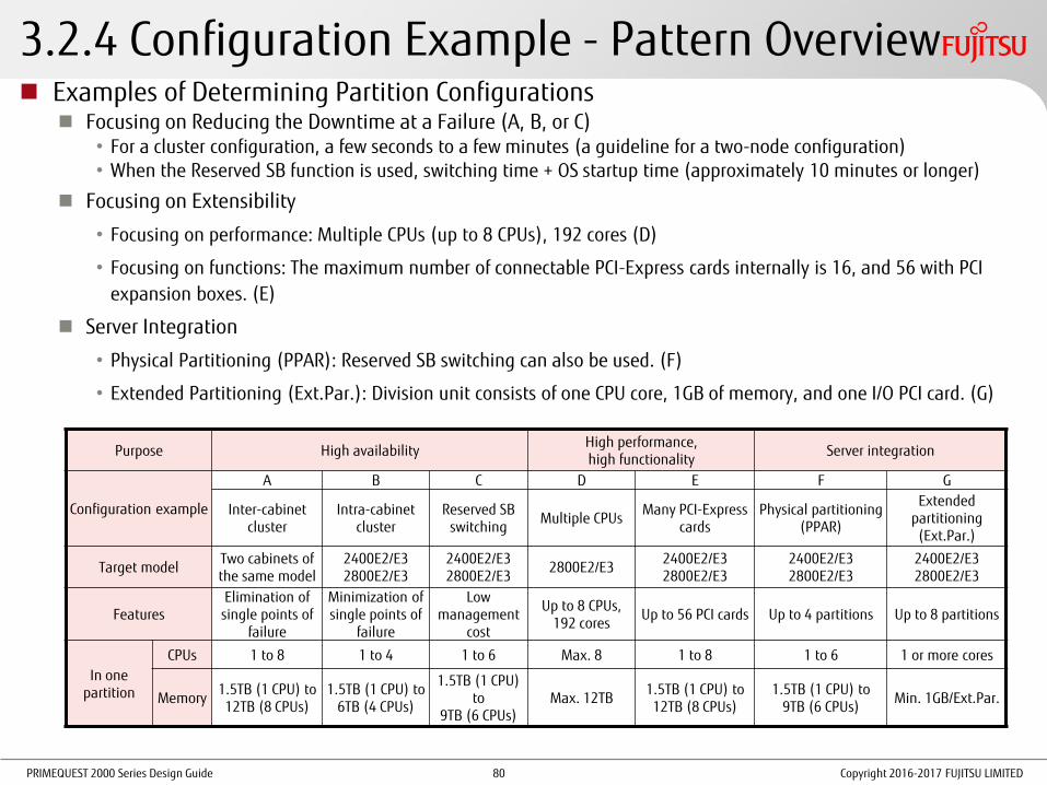
3.2.4 Configuration Example - Pattern Overview Examples of Determining Partition Configurations
Focusing on Reducing the Downtime at a Failure (A, B, or C) • For a cluster configuration, a few seconds to a few minutes (a guideline for a two-node configuration) • When the Reserved SB function is used, switching time + OS startup time (approximately 10 minutes or longer)
Focusing on Extensibility
• Focusing on performance: Multiple CPUs (up to 8 CPUs), 192 cores (D)
• Focusing on functions: The maximum number of connectable PCI-Express cards internally is 16, and 56 with PCI
expansion boxes. (E)
Server Integration
• Physical Partitioning (PPAR): Reserved SB switching can also be used. (F)
• Extended Partitioning (Ext.Par.): Division unit consists of one CPU core, 1GB of memory, and one I/O PCI card. (G)
Copyright 2016-2017 FUJITSU LIMITED
Purpose High availability High performance, high functionality
Server integration
Configuration example
A B C D E F G
Inter-cabinet cluster
Intra-cabinet cluster
Reserved SB switching
Multiple CPUs Many PCI-Express
cards Physical partitioning
(PPAR)
Extended partitioning (Ext.Par.)
Target model Two cabinets of the same model
2400E2/E3 2800E2/E3
2400E2/E3 2800E2/E3
2800E2/E3 2400E2/E3 2800E2/E3
2400E2/E3 2800E2/E3
2400E2/E3 2800E2/E3
Features Elimination of
single points of failure
Minimization of single points of
failure
Low management
cost
Up to 8 CPUs, 192 cores
Up to 56 PCI cards Up to 4 partitions Up to 8 partitions
In one partition
CPUs 1 to 8 1 to 4 1 to 6 Max. 8 1 to 8 1 to 6 1 or more cores
Memory 1.5TB (1 CPU) to 12TB (8 CPUs)
1.5TB (1 CPU) to 6TB (4 CPUs)
1.5TB (1 CPU) to
9TB (6 CPUs) Max. 12TB
1.5TB (1 CPU) to 12TB (8 CPUs)
1.5TB (1 CPU) to 9TB (6 CPUs)
Min. 1GB/Ext.Par.
80

PRIMEQUEST 2000 Series Design Guide
Cluster system #1
Cluster system #2
Copyright 2016-2017 FUJITSU LIMITED
3.2.4 Configuration Example (A) - Inter-Cabinet Cluster
Complete elimination of both single points of failure and shared components Cluster configuration between two cabinets with the same specifications, Memory
Mirror configuration Clustering between Cabinet#0 and Cabinet#1: If a failure occurs, node switching occurs
immediately and the system operation continues. Example: High-reliability database for a large number of users that is installed in
multiple cabinets
SB
CPU CPU
Memory Memory
IO unit
PCI card
PCI card
IO unit
PCI card
PCI card
SB
CPU CPU
Memory Memory
IO unit
PCI card
PCI card
IO unit
PCI card
PCI card
SB
CPU CPU
Memory Memory
IO unit
PCI card
PCI card
IO unit
PCI card
PCI card
SB
CPU CPU
Memory Memory
IO unit
PCI card
PCI card
IO unit
PCI card
PCI card
Redundancy Redundancy Redundancy Redundancy Redundancy Redundancy Redundancy Redundancy
Memory Memory Memory Memory Memory Memory Memory Memory Memory Mirror
PRIMEQUEST 2400E3 (Cabinet#0) PRIMEQUEST 2400E3 (Cabinet#1)
81

PRIMEQUEST 2000 Series Design Guide
Cluster system
Copyright 2016-2017 FUJITSU LIMITED
3.2.4 Configuration Example (B) - Intra-Cabinet Cluster
Minimization of single points of failure (The cabinet and the midplane are single points of failure. However, the possibility of failure is very small
because no electronic parts are contained.)
Cluster configuration between PPAR blocks with the same specifications in a cabinet, Memory Mirror configuration
Clustering between PPAR#0 and PPAR#1: If a failure occurs, node switching occurs immediately and the system operation continues.
Cluster configuration for small-sized installation (installation of one PRIMEQUEST)
Example: High-reliability database for a user base that is small to medium sized, vSphereHA.
SB
CPU CPU
Memory Memory
IO unit
PCI card
PCI card
IO unit
PCI card
PCI card
SB
CPU CPU
Memory Memory
IO unit
PCI card
PCI card
IO unit
PCI card
PCI card
Redundancy Redundancy Redundancy Redundancy
Memory Memory Memory Memory Memory Mirror
PRIMEQUEST 2400E3
Partition#0 Partition#1
82
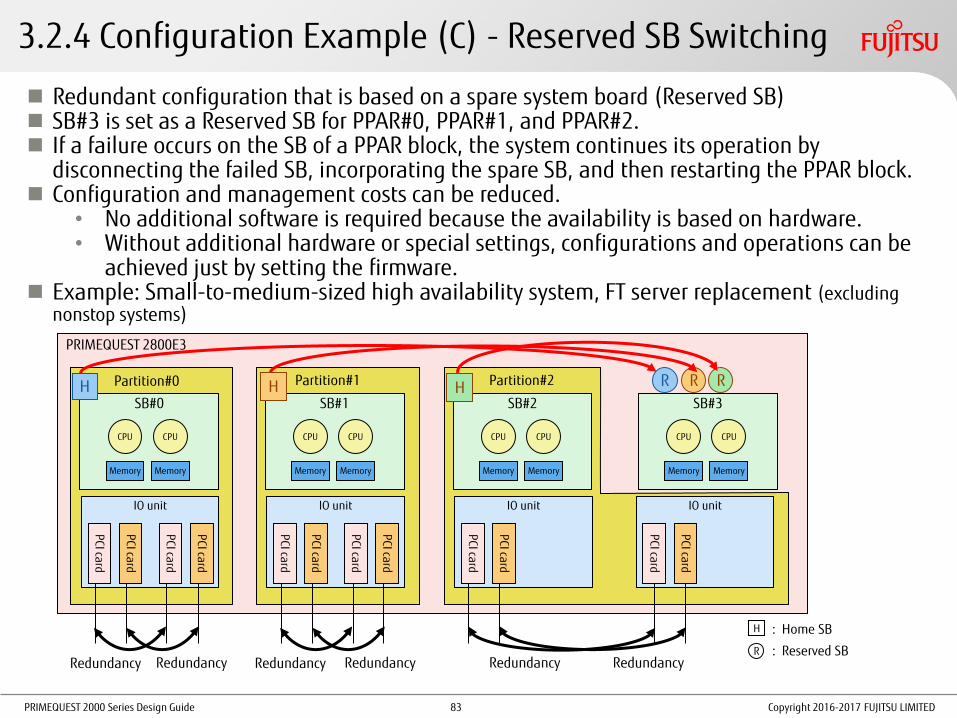
PRIMEQUEST 2000 Series Design Guide Copyright 2016-2017 FUJITSU LIMITED
3.2.4 Configuration Example (C) - Reserved SB Switching
R : Reserved SB
H : Home SB
Redundant configuration that is based on a spare system board (Reserved SB) SB#3 is set as a Reserved SB for PPAR#0, PPAR#1, and PPAR#2. If a failure occurs on the SB of a PPAR block, the system continues its operation by
disconnecting the failed SB, incorporating the spare SB, and then restarting the PPAR block. Configuration and management costs can be reduced.
• No additional software is required because the availability is based on hardware. • Without additional hardware or special settings, configurations and operations can be
achieved just by setting the firmware. Example: Small-to-medium-sized high availability system, FT server replacement (excluding
nonstop systems)
SB#0
CPU CPU
Memory Memory
IO unit
PCI card
PCI card
PCI card
PCI card
SB#1
CPU CPU
Memory Memory
IO unit
PCI card
PCI card
PCI card
PCI card
Redundancy Redundancy Redundancy Redundancy
SB#2
CPU CPU
Memory Memory
IO unit
PCI card
PCI card
SB#3
CPU CPU
Memory Memory
IO unit
PCI card
PCI card
Redundancy Redundancy
Partition#0 Partition#1 Partition#2
PRIMEQUEST 2800E3
R R R H H H
83

PRIMEQUEST 2000 Series Design Guide Copyright 2016-2017 FUJITSU LIMITED
3.2.4 Configuration Example (D) - High Performance Multiple CPUs
High-performance configuration: Up to 8 CPUs and 192 cores per partition Behavior at a CPU failure
• If a core failure occurs, then the system degrades the core, restarts the partition, and continues the operation.
• If a failure other than a core failure occurs, then the system disconnects the SB that contains the failed part, restarts the partition with 6-CPU configuration, and continues the operation.
Example: In-memory high performance database, SAP HANA
SB
CPU CPU
Memory Memory
SB
CPU CPU
Memory Memory
SB
CPU CPU
Memory Memory
IO unit
SB
CPU CPU
Memory Memory
IO unit
Partition#0
IO unit IO unit
Memory Memory Memory Memory Memory Memory Memory Memory Memory Mirror
PRIMEQUEST 2800E3
84
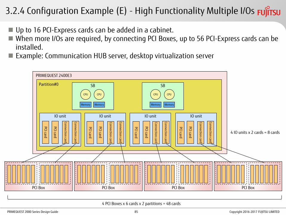
PRIMEQUEST 2000 Series Design Guide Copyright 2016-2017 FUJITSU LIMITED
3.2.4 Configuration Example (E) - High Functionality Multiple I/Os
Up to 16 PCI-Express cards can be added in a cabinet. When more I/Os are required, by connecting PCI Boxes, up to 56 PCI-Express cards can be
installed. Example: Communication HUB server, desktop virtualization server
SB
CPU CPU
Memory Memory
SB
CPU CPU
Memory Memory
Partition#0
IO unit
Conn
ection card
PCI card
PCI card
Conn
ection card
PCI Box
PCI Box
PCI Box
PCI Box
IO unit
Conn
ection card
PCI card
PCI card
Conn
ection card
IO unit
PCI card
PCI card
IO unit
PCI card
PCI card
Conn
ection card
Conn
ection card
Conn
ection card
Conn
ection card
4 PCI Boxes x 6 cards x 2 partitions = 48 cards
4 IO units x 2 cards = 8 cards
PRIMEQUEST 2400E3
85

PRIMEQUEST 2000 Series Design Guide Copyright 2016-2017 FUJITSU LIMITED
3.2.4 Configuration Example (F) - Physical Partitioning
System boards and IO units in a cabinet are combined and divided into PPAR blocks. PPAR blocks are independent of each other. The hardware configuration and OS can be
different between the PPAR blocks. Each PPAR block consists of at least one SB, at most four SBs (for 2800E2/2800E3) or
two SBs (for 2400E2/2400E3), and at least one IOU. After the initial build, the configuration can be modified based on the operation condition.
* When Dynamic Reconfiguration is not used, the PPAR block to be modified must be stopped.
Example: Server integration, enhancement of the future scale-up range of a server
SB
CPU CPU
Memory Memory
IO unit
PCI card
PCI card
PCI card
PCI card
SB
CPU CPU
Memory Memory
IO unit
PCI card
PCI card
PCI card
PCI card
Redundancy Redundancy Redundancy Redundancy
Partition#0 Partition#1
SB
CPU CPU
Memory Memory
Partition#2
SB
CPU CPU
Memory Memory
PRIMEQUEST 2800E3
IO unit
PCI card
PCI card
IO unit
PCI card
PCI card
Redundancy Redundancy
86

PRIMEQUEST 2000 Series Design Guide
Each physical partition is divided into smaller partitions. Partitions are independent of each other. The hardware configuration and OS can be
different between the partitions. The minimum division unit consists of one CPU core, 1GB of memory, and one I/O PCI card. After the initial build, the configuration can be modified based on the operation condition.
Note: Memory Scale-up Boards can be used, however Dynamic Reconfiguration cannot be used.
Example: Physical integration of small-sized servers
Physical Partition#2
Copyright 2016-2017 FUJITSU LIMITED
3.2.4 Configuration Example (G) - Extended Partitioning
SB
IO unit
PCI card
PCI card
PCI card
PCI card
SB
IO unit
PCI card
PCI card
PCI card
PCI card
Physical Partition#0 Physical Partition#1
SB
IO unit
PCI card
PCI card
PCI card
PCI card
SB
IO unit
PCI card
PCI card
PCI card
PCI card
Ext.Par.#0 Ext.Par.#1
PRIMEQUEST 2800E3
Mem
ory
Mem
ory
Mem
ory
Mem
ory
Mem
ory
Mem
ory
Mem
ory
Mem
ory
Mem
ory
Mem
ory
Mem
ory
Mem
ory
Mem
ory
Mem
ory
Mem
ory
Mem
ory
Core
Core
Core
Core
Core
Core
Core
Core
Core
Core
Core
Core
Core
Core
Core
Core
Core
Core
Core
Core
Core
Core
Core
Core
Core
Core
Core
Core
Core
Core
Core
Core
Core
Core
Core
Core
Core
Core
Core
Core
Ext.Par.
#2 Ext.Par.#3
Core
Core
Core
Core
Core
Core
Core
Core
Core
Core
Core
Core
Core
Core
Core
Core
Core
Core
Core
Core
Core
Core
Core
Core
Core
Core
Core
Core
Core
Core
Core
Core
Core
Core
Core
Core
Core
Core
Core
Core
Ext.Par.#5 Ext.Par.
#4
87

PRIMEQUEST 2000 Series Design Guide
3.3 Key Points for I/O Configuration Design Boot Type Selection
For details, refer to "3.3.1 Boot Type Selection".
Guidelines for Selecting Internal Storage For details, refer to "3.3.2 Guidelines for Selecting Internal Storage".
Obtaining RAID Cards and FBUs For details, refer to "3.3.3 Obtaining RAID Cards and FBUs".
HDD Configuration For details, refer to "3.3.4 HDD Configuration".
Guidelines for Selecting a RAID Configuration for HDDs • Software RAID •Hardware RAID • SAN boot
Memory Dump Function
Network Configuration For details, refer to "3.3.5 Network Configuration".
Network Types and Usage Network Redundancy
I/O Space Settings for PCI Devices For details, refer to "3.3.6 Setting I/O Space for PCI Devices".
I/O space assignment setting
Copyright 2016-2017 FUJITSU LIMITED 88

PRIMEQUEST 2000 Series Design Guide
3.3.1 Boot Type Selection
Boot type Boot devices Usage
Internal HDD or SAS-SSD (*1) DU
Internal disk for an SB Boot an OS that is installed in an internal HDD.
External HDD cabinet JX40 S2 with a SAS card for connection Boot an OS that is installed in an external HDD cabinet.
FC boot in an external file unit (SAN environment)
FC card Boot an OS that is installed in an external disk array device.
FCoE boot in an external file unit (SAN environment)
CNA Boot an OS that is installed in an external disk array device.
iSCSI boot in an external file unit (SAN environment)
LAN card, and LAN port on an IOU Boot an OS that is installed in an external disk array device.
Preboot eXecution Environment (PXE) LAN card, and LAN port on an IOU Boot via remote operation.
Boot from a virtual media Device or file that is set as a virtual media Boot from a device or file that is set as a virtual media.
Boot from a device connected to the front USB port on the Home SB
USB connected device (e.g. CD and DVD) Boot from a USB connected device that is used temporarily for operations such as system configuration. (This operation is not available when the front bezel is removed.)
It is recommended to use a redundant HDD (hardware RAID or software RAID) as a boot HDD.
When an internal disk is used as a boot device, RAID is configured at the same time as the OS installation using ServerView Installation Manager (SVIM).
(*1) For details on the internal storage in the cabinet, refer to "3.3.2 Guidelines for Selecting Internal Storage".
Copyright 2016-2017 FUJITSU LIMITED 89

PRIMEQUEST 2000 Series Design Guide Copyright 2016-2017 FUJITSU LIMITED
3.3.2 Guidelines for Selecting Internal Storage
RAID Cards or HDDs/SAS-SSDs in DUs and SBs
Item Installed in DUs
(shared between partitions)
Installed in DUs (not shared between
partitions) Installed in SBs
Supported models All models 2400E2/E3, 2800E2/E3
Number of RAID cards 2 1 Up to 1
Number of HDDs Up to 2 per RAID card UP to 4 Up to 4
When a Reserved SB switching occurs
Internal storage is automatically connected to the switched partition Internal storage is isolated
(unavailable)
Intra-cabinet cluster configuration
The number of partitions that are used (up to 2) must be stopped at the same time when maintenance is being performed
No partitions need to be stopped at the same time because internal storage is not shared between the partitions
Connection source
Shared Not shared
IOU#0 DU#0 RAID#0 HDD #2/3
DU#0 RAID#0 HDD #0/1/2/3
IOU#1 DU#0 RAID#1 HDD #0/1
DU#0 RAID#1 HDD #0/1/2/3
IOU#2 DU#1 RAID#0 HDD #2/3
DU#1 RAID#0 HDD #0/1/2/3
IOU#3 DU#1 RAID#1 HDD #0/1
DU#1 RAID#1 HDD #0/1/2/3
DU
(LDU#1)
RAID card #0
HDD#2
HDD#3
RAID card #1
HDD#0
HDD#1
IOU #0 or 2 IOU #1 or 3
SB #m SB #n
HDD#3
IOU #0 or 2
SB #m
HDD#2
HDD#1
HDD#0
DU
HDD#3
RAID card #0
IOU #1 or 3
SB #n
HDD#2
HDD#1
HDD#0
RAID card #1 RAID
card #1
RAID card #0
90

PRIMEQUEST 2000 Series Design Guide Copyright 2016-2017 FUJITSU LIMITED
3.3.3 Obtaining RAID Cards and FBUs
RAID Cards in SBs A SAS array controller card installation kit is required
Obtain FBUs (Flash Backup Unit) (optional)
Obtain RAID software licenses (optional)
RAID Cards in DUs Obtain FBUs (optional) for each RAID card
Obtain RAID software licenses (optional)
RAID Cards in 1GbE IO Units (for JX40 S2 Connection) Obtain FBUs (optional) for each RAID card (installed in Slot#1 and Slot#2)
Obtain FBUs (optional) (different from the FBUs for SBs/DUs)
Obtain an FBU installation kit (this kit uses Slot#0 exclusively)
FBUs cannot be connected to RAID cards that are installed in 10GbE IO units, PCI Boxes, or Slot#3 on 1GbE IO units.
91

PRIMEQUEST 2000 Series Design Guide
3.3.4 HDD Configuration (1/5)
Guidelines for Selecting a RAID Configuration for HDDs Redundancy with "SAN boot + multipath driver" is recommended for reliability.
Item
Software RAID Hardware RAID
SAN boot + multipath driver OS standard PRIMECLUSTER GDS Inside of an SB or DU (*1) External hard disk cabinet (JX40 S2)
OS (*2) Supported with RHEL Supported Supported Supported
High-speed access Relatively slow Relatively slow Supported Supported Supported
Card duplication Supported Supported Not supported Not supported Supported
Path duplication Supported Supported Not supported Not supported Supported
RAID level Depends on the software 1 1, 1E, 5, 6, 10 Available at the RAID levels that are
supported by the SAS array controller card that is connected to JX40 S2
Available at the RAID level of the storage device being used
Device duplication at boot time
Not supported Supported Supported Supported Supported
Notes (1/2) • If an unpredictable power supply problem occurs, data in the cache (*) that is equipped in a
hardware RAID or disk may be lost. To avoid such a problem, make sure to consider installing a redundant power supply or dual power feed option as well as a CVCF or UPS.
(*) A hardware RAID uses the cache on the hardware when Write Back or Always Write Back is specified. A disk uses the cache on the hardware when the disk cache is enabled.
Copyright 2016-2017 FUJITSU LIMITED
(*1) For details, refer to "3.3.2 Guidelines for Selecting Internal Storage".
(*2) For details on the supported OSs or virtualization software, refer to the related documents of the OS or virtualization software.
92

PRIMEQUEST 2000 Series Design Guide
3.3.4 HDD Configuration (2/5)
Notes (2/2) • When internal HDDs are used, the hardware RAID controller may fail to fully detect failures on a hard disk,
and a system slowdown may occur.
[Additional Notes]
If intermittent media errors occur on a HDD, a slowdown may occur on rare occasions.
This problem may occur for example due to many scratches in a wide area on the HDD. The RAID controller tries to replace the media error area and salvage data using RAID parity. Therefore, if intermittent media errors occur over a long time, the salvage processing takes a longer time and the conventional media access processing is delayed.
If there are restrictions in operation, the following options are recommended. - Use ETERNUS. - Replace the HDD with a SAS-SSD.
• When using an internal SSD for a PCI slot, note the following points.
- The SSD cannot be used as a boot drive.
- When a failed SSD is replaced, the integrity of the data in the drive cannot be guaranteed. Reliability design including recovery from a regular backup and software RAID configuration is required to prepare for possible risks.
• When using an internal HDD in an SB, note the following points.
When the HDD is used as a boot drive or a data disk and the Reserved SB function is used, the HDD cannot be started or operated.
Copyright 2016-2017 FUJITSU LIMITED 93

PRIMEQUEST 2000 Series Design Guide
OS
3.3.4 HDD Configuration (3/5) Software RAID
• RHEL standard RAID function
For details, refer to "Linux (RHEL) Design Guide".
• Mirroring with PRIMECLUSTER GDS is supported.
For details on support information, refer to
"Linux (RHEL) Design Guide".
Hardware RAID • Hard disk redundancy for disk units and SBs
•A RAID card is included by default in a DU to support RAID configurations.
•RAID0, RAID1, RAID1E, RAID5, RAID6, and RAID10 can be configured.
•Hot swapping internal HDDs is supported (excluding RAID0 and non-mirror configurations).
•RAID management tool "ServerView RAID Manager" is supported. (This tool is bundled with the main server unit by default).
• Hard disk redundancy on an external file unit
•A RAID configuration can be created in the file unit on an external storage device (such as ETERNUS).
For details, refer to the manual for the file unit.
•RAID0, RAID1, RAID1E, RAID5, RAID6, RAID10, RAID50, and RAID60 can be configured.
•Hot swapping internal HDDs is supported (excluding RAID0 and non-mirror configurations).
•RAID management tool "ServerView RAID Manager" is supported. (This tool is bundled with the main server unit by default).
For details, refer to "SAS3 12 Gb/s MegaRAID® SAS Software User Guide" and "FUJITSU Software ServerView Suite ServerView RAID Manager User Guide".
SAN Boot An OS is started from a boot disk that is set in an external storage.
OS
RAID CARD
HDD HDD
Hardware RAID
GDS
HDD HDD
Software RAID
Copyright 2016-2017 FUJITSU LIMITED 94

PRIMEQUEST 2000 Series Design Guide
3.3.4 HDD Configuration (4/5)
Memory Dump Function for Windows (OS Standard Function) If a fatal system error occurs, data in the physical memory is output to a file. Dump Types and Estimated Sizes
Mechanism for Acquiring Dump Information 1. If a system failure occurs, dump information is output to the paging file in the boot volume. 2. After the OS is restarted, a tentative paging file is created, and the acquired dump information is
moved to the specified save destination.
Windows
STOP error
Acquire memory dump information
Store to a save destination
Dump type Description Dump file size
Complete memory dump Records all data that exists in the physical memory when the system stops.
Physical memory size + 300MB
Kernel memory dump Records the information only in the kernel memory space. Depends on the memory space during system operation.
Minimum memory dump Records the minimum information that is useful for identifying the problem.
128KB or 256KB
Automatic memory dump Records information that is equivalent to the conventional kernel memory dump.
The following points are different from the kernel memory dump.
The initial value of the paging file size is smaller than the kernel memory dump size.
If part of the information in the kernel memory space cannot be recorded, the page file size is automatically extended after the next startup. (If part of the information in the kernel memory space cannot be recorded, acquisition of memory dump information may fail.)
For details, refer to "13.4.3 Setting up the dump environment (Windows)" in "Administration Manual".
Work
Copyright 2016-2017 FUJITSU LIMITED 95

PRIMEQUEST 2000 Series Design Guide
3.3.4 HDD Configuration (5/5)
Memory Dump Function for RHEL If a fatal system error occurs, data in the physical memory is output to a file.
Dump Types and Estimated Sizes sadump (a dedicated tool for PRIMEQUEST) kdump (OS standard function)
Dump acquisition area (Dump device for sadump) (Temporary data storage area) Internal disk => OK External disk => OK Cluster sharing is not allowed.
Installed memory capacity + 512MB * Required
Alternative area that is used if a device error occurs
(Installed memory capacity + 512MB)
:
N areas
(Installed memory capacity + 1GB) / 0.9 (1st generation) * Required
:
Error
Error
Acqu
isition
(Installed memory capacity + 1GB) / 0.9 (2nd generation)
Save data to a disk that is not managed
with GDS (RAW device)
Save data to a disk that is not
managed with GDS
When creating a dedicated disk partition (such as /var/crash) for saving dump data, increase the acquisition area size for kdump by 10% in consideration of the file system management area.
Acquisition area for kdump
* Non-Fujitsu storage devices cannot be used for dump areas for sadump.
Copyright 2016-2017 FUJITSU LIMITED 96

PRIMEQUEST 2000 Series Design Guide
3.3.5 Network Configuration (1/5) Network Types Connect with different types of networks for various intended purposes to achieve security and load
balancing.
Operation LAN The LAN that is used by the customer
Management LAN The LAN for connecting each partition and MMB to external servers such as the operation management server
Cluster LAN (Cluster interconnect or private network)
•The LAN that allows mutual status monitoring between nodes in a cluster configuration
•Use a subnet that is different from the one for other LANs (such as the operation LAN).
For details, refer to "3.4 Key Points for Cluster Configurations".
Internal LAN The LAN for connecting each partition to MMBs for internal communication
Maintenance LAN The LAN that is used for maintenance • For connecting a maintenance terminal (port for maintenance)
On the external switching hub device for connecting to the management LAN for MMBs, select [Disable] for the spanning tree protocol function.
Management server
Management LAN
MMB#0 User port
REMCS port
Port for maintenance
Partition PCH
MMB#1 User port
REMCS port
Port for maintenance
Cabinet
Operation LAN
Cluster LAN
Internal LAN
* Specify different subnets for the management LAN, cluster LAN, internal LAN, and maintenance LAN. * When counting the number of LAN ports that are required for a partition, consider that two ports are used for the management LAN.
Copyright 2016-2017 FUJITSU LIMITED
Maintenance terminal
Maintenance LAN
97

PRIMEQUEST 2000 Series Design Guide
PCI Express Slots
Partition A Partition B
LAN
3.3.5 Network Configuration (2/5)
Redundancy of Internal Ports Concepts of Reliable Configurations
When configuring partitions with multiple components, install internal ports on different components.
Example of IOUs Separate IOUs from each other.
IOU#1
PCI Express Slots
LAN
IOU#0
Copyright 2016-2017 FUJITSU LIMITED 98

PRIMEQUEST 2000 Series Design Guide
IOU
1000Base-T (Dual)
PCI Express card
FC card (Dual)
1000Base-T (Dual)
FC card (Dual)
Duplicated
- FC card (Single) => FC card (multiple channels)
- Unused 1000Base-T ports are used.
Duplicated
Duplicated
Duplicated 1000Base-T (Dual) Duplicated
This configuration is not correct because the duplication does not make sense if the PCI Express card fails.
Incorrect Example
Advantage: The numbers of extended I/O cabinets and PCI Boxes can be reduced.
Disadvantage: If the PCI Express card fails, multiple ports cannot be used.
* Because the card is duplicated, the system can continue to operate safely.
3.3.5 Network Configuration (3/5) Configuration That Focuses on Redundancy Multiple channel ports on a PCI Express card are used effectively.
Copyright 2016-2017 FUJITSU LIMITED
PCI Box connection card
PCI Box
1000Base-T (Dual)
FC card (Single)
Empty
1000Base-T (Dual)
FC card (Single)
Empty
Not used
Not used
Duplicated
Duplicated
PCI Box LH #0
PCI Box LH #1
PCI Box connection card
IOU PCI Express card
Configuration That Focuses on Hot Swap Considering the range of impact during a PCI Express card failure, for connections with a PCI
Express card (single card), only one port is used when using a multi-port card.
99

PRIMEQUEST 2000 Series Design Guide
Network Configuration Redundancy with an Onboard LAN A network configuration can be duplicated by using an Onboard LAN.
* When an onboard LAN is used, before maintenance is performed on an IOU,
all partitions that use the IOU must be stopped.
Redundant Configuration for the Management LAN The management LAN can be recovered when an error occurs by creating a redundant
configuration of the user ports on the MMBs that are connected to the management LAN with tools such as the bonding driver, PRIMECLUSTER GLS, and Intel® PROSet.
When MMBs are duplicated but user ports are not, the active MMB must be switched manually if an MMB fails.
For details, refer to "1.3.3 Redundant configuration of the management LAN" in "Administration Manual".
3.3.5 Network Configuration (4/5)
Copyright 2016-2017 FUJITSU LIMITED
IOU
PCI Box
LAN card
LAN card
Onboard
LAN card
LAN card
Can be duplicated
Can be duplicated
PCI Box connection card
PCI Box connection card
Can be duplicated
100

PRIMEQUEST 2000 Series Design Guide
3.3.5 Network Configuration (5/5)
InfiniBand Network Configuration Redundancy
Copyright 2016-2017 FUJITSU LIMITED
IOU
PCI Box
IB card
IB card
IB card
IB card
Can be duplicated PCI Box connection card
PCI Box connection card Can be duplicated
Can be duplicated
IOU IB card
Can be duplicated
Replacement of an Ethernet Environment with InfiniBand Cards InfiniBand cards with a wide bandwidth of 40Gbps or 56Gbps can accommodate more networks
than when a 10GbE environment is used.
InfiniBand cards can be used for the paths to synchronize databases. Use of InfiniBand cards with PCIe SSDs can provide better results within the network.
101

PRIMEQUEST 2000 Series Design Guide
3.3.6 Setting I/O Space for PCI Devices (1/2)
To perform a boot in a legacy BIOS environment, it is necessary to assign the I/O space to the boot device.
The size of the I/O space is 64KB for all models.
A 4KB area of the I/O space can be assigned per device.
The assignment is possible for up to 15 devices (that is, 16 devices in total including one device that is reserved for a PCH). The following devices can be assigned:
- Onboard LANs
- RAID cards in SBs
- RAID cards in DUs
- PCI Express slots on IOUs
- PCI Boxes
Copyright 2016-2017 FUJITSU LIMITED 102

PRIMEQUEST 2000 Series Design Guide
3.3.6 Setting I/O Space for PCI Devices (2/2)
Select one of the following two assignment types and set the assignment in the "Device Manager menu" of the UEFI.
* When auto assignment is used for some devices and forced assignment is used for other devices in the same system, auto assignment is performed after forced assignment is set (and a system reset is performed).
• Forced assignment of the I/O space
•Reserve an I/O resource for each device (including onboard devices such as IOUs) for I/O resources and PCI Express cards that are included in a partition.
• This type of assignment is useful for assigning I/O space to specific devices and cards if there are more than 16 devices that require the I/O space.
• Auto assignment of the I/O space
• This type of assignment is easy to use and can be implemented when the partition configuration is relatively small and 16 or less devices require the I/O space.
For details, refer to "3.4 [Device Manager] Menu" in "Tool Reference".
Copyright 2016-2017 FUJITSU LIMITED 103

PRIMEQUEST 2000 Series Design Guide
3.4 Key Points for Cluster Configurations (1/4)
Cluster operation with cluster operation software is supported to increase the system availability.
For details, refer to "Chapter 1 Product Overview" in "General Description".
Relationship Between Redundant Configurations and Reliability
Cost for Installation and Operation
Firm reliability of the cabinet Component redundancy (PSU, FAN, MMB, IOU, and so on)
Improved reliability of SBs and QPI network Flexible I/O mechanism Reserved SB (spare SB)
Firm reliability in the middle layer and application layer Inter-cabinet cluster (for securing work continuity) Intra-cabinet cluster (for improving work continuity) * Cluster software
Windows => Windows Server Failover Clustering (WSFC) RHEL => PRIMECLUSTER
Inter-cabinet cluster (Countermeasures against
server failures)
Intra-cabinet cluster (Countermeasures against
partition failures)
Flexible I/O + spare SB (Countermeasures against
CPU/SB failures)
Reliability
Redundancy of the power supply, fan, and so on
(Countermeasures against operation failure)
Disaster recovery (Countermeasures against
disaster)
Memory Mirror/ Memory Spare
(Countermeasures against memory failures)
Copyright 2016-2017 FUJITSU LIMITED
CPU
DIMM DIMM
CPU
CPU
DIMM DIMM
CPU
104

PRIMEQUEST 2000 Series Design Guide
3.4 Key Points for Cluster Configurations (2/4)
Cluster System Overview
•A dedicated LAN for inter-node communication is used to connect between nodes.
•Private network is used for Windows.
•Cluster interconnect is used for Linux.
•Inter-node communication is performed periodically to monitor for problems.
•There are two types of cluster systems: inter-cabinet cluster and intra-cabinet cluster.
For details, refer to "3.4.1 Inter-Cabinet Cluster" and "3.4.2 Intra-Cabinet Cluster".
•Windows
Clustering with Windows Server Failover Clustering (OS standard function) is recommended.
* A server for Active Directory (AD server) is required separately.
•RHEL
Clustering with PRIMECLUSTER is recommended.
Copyright 2016-2017 FUJITSU LIMITED 105

PRIMEQUEST 2000 Series Design Guide
Possible Combinations of PRIMEQUEST Cluster Configurations (1/2) • Inter-Cabinet Cluster
• Clustering between different models is not supported. • Each node consists of the same model in the same configuration
(in the number of CPUs, CPU frequency, memory capacity, HDD capacity, and number of HDDs).
• Intra-Cabinet Cluster • All nodes have the same configuration (in the number of CPUs,
CPU frequency, memory capacity, HDD capacity, and number of HDDs).
• If an IOU fails, the redundancy of the system is lost and components such as the midplane become single points of failure.
3.4 Key Points for Cluster Configurations (3/4)
Copyright 2016-2017 FUJITSU LIMITED 106

PRIMEQUEST 2000 Series Design Guide
3.4 Key Points for Cluster Configurations (4/4)
Possible Combinations of PRIMEQUEST Cluster Configurations (2/2) The following table shows whether OracleDB is supported as the cluster management DB software.
OS Cluster software Configuration 2800B2/2800B3 2400E2/2400E3 2800E2/2800E3
RHEL
PRIMECLUSTER (excluding RAC)
Intra-cabinet No Yes* Yes
Inter-cabinet Yes* Yes* Yes*
PRIMECLUSTER (RAC) Intra-cabinet/ inter-cabinet
No No No
Oracle Clusterware (SE2-RAC)
Intra-cabinet No No No
Inter-cabinet No No No
Oracle Clusterware (EE-RAC)
Intra-cabinet Yes* Yes* Yes*
Inter-cabinet Yes* Yes* Yes*
Windows
WSFC (excluding RAC) Intra-cabinet No Yes* Yes
Inter-cabinet Yes* Yes* Yes*
WSFC (RAC) Intra-cabinet/ inter-cabinet
No No No
Oracle Clusterware (SE2-RAC)
Intra-cabinet No No No
Inter-cabinet No No No
Oracle Clusterware (EE-RAC)
Intra-cabinet Yes* Yes* Yes*
Inter-cabinet Yes* Yes* Yes*
Note: When RAC is used, PRIMECLUSTER and WSFC cannot be used together with RAC. Use Oracle Clusterware.
RAC: Oracle Real Application Clusters
WSFC: Windows Server Failover Clustering
Yes*: Supported and recommended (IOU redundancy configuration is allowed)
Yes: Supported and recommended
No: Not supported
Copyright 2016-2017 FUJITSU LIMITED 107

PRIMEQUEST 2000 Series Design Guide
3.4.1 Inter-Cabinet Cluster
A cluster configuration for communication between PRIMEQUEST nodes (cabinets)
Linux
The cluster interconnect is configured separately from the operation LAN and management LAN.
Partition#0
Cluster software
BMC MMB#0
(Active)
MMB#1
(Standby)
Cabinet#0 Partition#0
Cluster software
BMC MMB#0
(Active)
MMB#1
(Standby)
Cabinet#1
Cluster interconnect
Operation LAN
Management LAN
Windows
The private network is configured separately from the public network (operation LAN).
Cabinet#1 Partition#0
Cluster service
Cabinet#0 Partition#0
Cluster service
AD server
Private network
Public network (operation LAN)
Teaming
Copyright 2016-2017 FUJITSU LIMITED
SVmco SVmco
108

PRIMEQUEST 2000 Series Design Guide
3.4.2 Intra-Cabinet Cluster
A cluster configuration for communication between nodes (partitions) that are created in a cabinet
By configuring both active and standby systems in a cabinet, availability of the entire system including the software layer is ensured.
Windows
Partition#X
Cluster service
AD server
Private network Public network
(Operation LAN)
Partition#Y
Cluster service
Copyright 2016-2017 FUJITSU LIMITED
Linux
MMB#0
(Active)
MMB#1
(Standby)
Cluster interconnect
Operation LAN
Partition#X
Cluster software
BMC
Partition#Y
Cluster software
BMC
Management LAN
SVmco SVmco
(e.g. PRIMECLUSTER) Clustering
(WSFC) Clustering
109

PRIMEQUEST 2000 Series Design Guide
3.5 Key Points for Power Supply
Power Supply Redundancy For details, refer to "3.5.1 Power Supply Redundancy".
Examples of single power feed and dual power feed
UPS Redundancy For details, refer to "3.5.2 UPS Redundancy".
Guidelines for Selecting a 200V Power Distribution Box For details, refer to "3.5.3 Guidelines for Selecting a 200V Power Distribution Box".
AC200V Power Distribution Box Brief Specifications
Guidelines on the Number of AC200V Power Distribution Boxes
Copyright 2016-2017 FUJITSU LIMITED 110
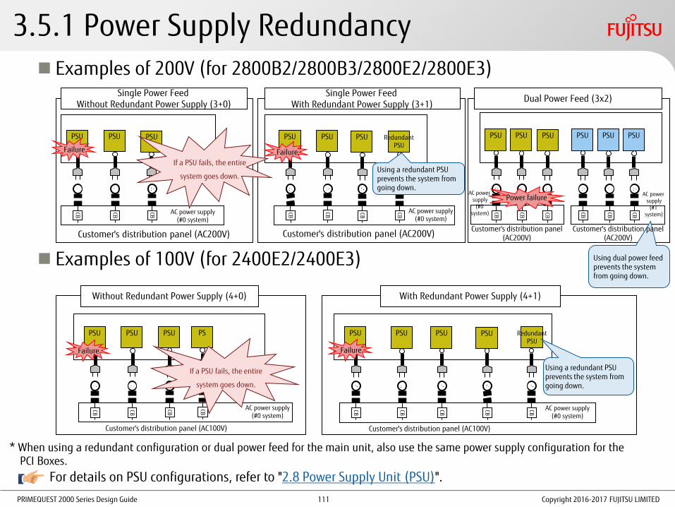
PRIMEQUEST 2000 Series Design Guide
Redundant PSU
3.5.1 Power Supply Redundancy Examples of 200V (for 2800B2/2800B3/2800E2/2800E3)
Examples of 100V (for 2400E2/2400E3)
CB
CB
Customer's distribution panel (AC200V)
AC power supply (#0 system)
PSU
PSU
Single Power Feed Without Redundant Power Supply (3+0)
CB
Customer's distribution panel (AC200V)
AC power supply (#0 system)
PSU
PSU
Single Power Feed With Redundant Power Supply (3+1)
Dual Power Feed (3x2)
AC power supply
(#0 system)
PSU
PSU
PSU
CB
AC power supply
(#1 system)
PSU
Using dual power feed prevents the system from going down.
Without Redundant Power Supply (4+0)
CB
Customer's distribution panel (AC100V)
AC power supply (#0 system)
PSU
PSU
PSU
Failure
With Redundant Power Supply (4+1)
CB
Customer's distribution panel (AC100V)
AC power supply (#0 system)
CB
PSU
PSU
CB
PSU
CB
* When using a redundant configuration or dual power feed for the main unit, also use the same power supply configuration for the PCI Boxes.
PSU
CB
PSU
CB
CB
Power failure
CB
PSU
Customer's distribution panel (AC200V)
If a PSU fails, the entire
system goes down.
Redundant PSU
CB
Using a redundant PSU prevents the system from going down.
PS
CB
If a PSU fails, the entire
system goes down.
PSU
CB
Using a redundant PSU prevents the system from going down.
CB
PSU
For details on PSU configurations, refer to "2.8 Power Supply Unit (PSU)".
Customer's distribution panel (AC200V)
Copyright 2016-2017 FUJITSU LIMITED
CB
CB
CB
CB
CB
Failure
Failure
Failure
111
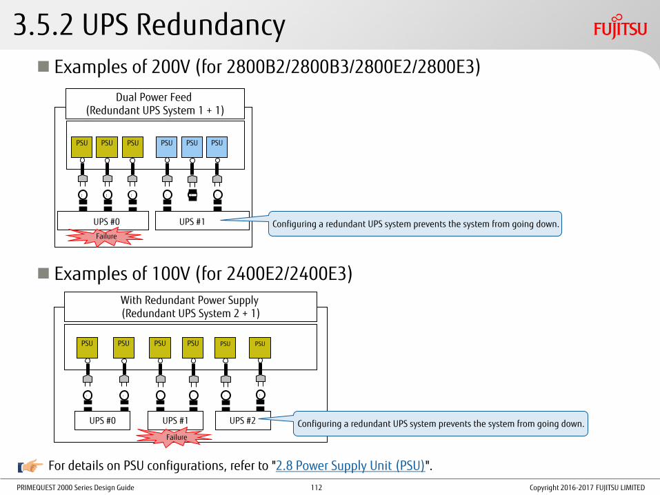
PRIMEQUEST 2000 Series Design Guide
3.5.2 UPS Redundancy Examples of 200V (for 2800B2/2800B3/2800E2/2800E3)
Examples of 100V (for 2400E2/2400E3)
For details on PSU configurations, refer to "2.8 Power Supply Unit (PSU)".
Copyright 2016-2017 FUJITSU LIMITED
Dual Power Feed (Redundant UPS System 1 + 1)
UPS #0
PSU
PSU
PSU
PSU
Configuring a redundant UPS system prevents the system from going down.
PSU
Failure
PSU
UPS #1
With Redundant Power Supply (Redundant UPS System 2 + 1)
PSU
PSU
PSU
PSU
PSU
PSU
UPS #0 UPS #1 UPS #2 Configuring a redundant UPS system prevents the system from going down.
Failure
112

PRIMEQUEST 2000 Series Design Guide
3.5.3 Guidelines for Selecting a 200V Power Distribution Box
AC200V Power Distribution Box Brief Specifications
Guidelines on the Number of AC200V Power Distribution Boxes
Copyright 2016-2017 FUJITSU LIMITED
U number Voltage Input Output Output current
1U 200V NEMA L6-30P IEC320 C19 3 24A/BOX 16A per box
0U 200V NEMA L6-30P IEC320 C19 3 24A/BOX 16A per box
Model 200V non-redundant
configuration 200V redundant
configuration 200V dual power feed
configuration
2400E2/2400E3 1 1 2
2400E2/2400E3 with Memory Scale-up Board
1 2 2
2800E2/2800E3 2 2 4
2800E2/2800E3, 2800B2/2800B3
(*1) (4,500VA or less) 1 2 2
(*1) Calculate the required number of power distribution boxes according to the maximum apparent power. The maximum apparent power can be calculated by using the Power Calculator ("Tool"). As the above example shows, if the maximum apparent power is 4.500VA or less , the number of power distribution boxes can be reduced.
113

PRIMEQUEST 2000 Series Design Guide Copyright 2016-2017 FUJITSU LIMITED
4. Operation Management Design
This chapter describes the key points for designing operation management.
For details, refer to "Administration Manual".
114

PRIMEQUEST 2000 Series Design Guide
Functions of Consoles
Action That Is Required When Reserved SB Switching Occurs If switching by the Reserved SB function occurs, the console connection must be changed.
4.1 Key Points for Console Operation (1/2)
Conn
ection
type
Console type Intended purposes Connection
target Remarks
Rem
ote
Video redirection Control and management of the OS in a partition (using images)
Management LAN
It is difficult to acquire operation logs or automate operations (log acquisition can be performed by using an application with a log acquisition function).
A PC in which JRE is installed must be connected to the management LAN.
If the resolution on the server is 800 x 600, part of the screen may not be displayed or trails of the mouse pointer may appear.
Text console Maintenance Management LAN
Copyright 2016-2017 FUJITSU LIMITED 115
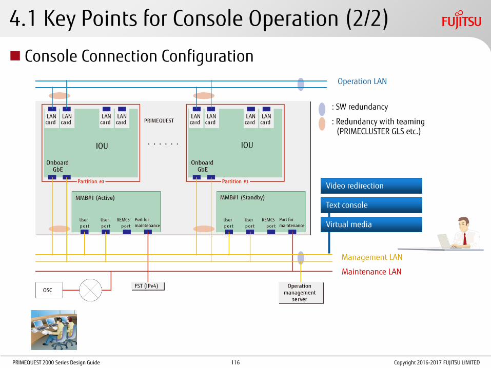
PRIMEQUEST 2000 Series Design Guide
4.1 Key Points for Console Operation (2/2)
Console Connection Configuration
: SW redundancy
: Redundancy with teaming (PRIMECLUSTER GLS etc.)
Virtual media
Video redirection
Text console
Management LAN
Maintenance LAN
Operation LAN
IOU IOU
Copyright 2016-2017 FUJITSU LIMITED 116

PRIMEQUEST 2000 Series Design Guide
Integrated management of different models through ServerView Resource Orchestrator V3 (optional)
4.2 Key Points for Server Operation Management (1/2)
Hardware management of a PRIMEQUEST server through the MMB Web-UI (agentless management)
Hardware management of multiple PRIMEQUEST and PRIMERGY servers through ServerView Suite
- Hardware status monitoring
- Hardware setting
- Power supply operation (turning on/off) etc. on a partition basis
http://www.fujitsu.com/global/products/computing/servers/mission-critical/primequest/technology/server-view.html
- Consolidated management and operability of multiple PRIMEQUEST servers in an integrated screen
- Functions for supporting the entire system life cycle that are provided to the managed servers
- Power supply operation and reboot operation for a partition that can be performed from a GUI
http://www.fujitsu.com/global/products/software/infrastructure-software/resource-management/serverview-resource-orchestrator/
- A single screen for displaying server information in which different operations and monitoring between platforms are integrated
- Server operations (start, stop, and reboot operations) through the screen (Automation with a CLI is also possible.)
- Functions for supporting the entire virtual environment operation (Integrated management of physical servers and virtual servers, simplified and visualized operation of virtual servers, and simplified maintenance)
Copyright 2016-2017 FUJITSU LIMITED
Storage
PRIMERGY
Network SV Agent
Operation management client
Operation management server
Management target: Resources
SV Agent
ServerView Resource Orchestrator
PRIMERGY MMB
GUI client
Operation management server
Operation target: Multiple PRIMEQUEST and PRIMERGY servers
PRIMERGY
MMB MMB
ServerView Operations Manager
SVAS SVAS SVAS
Management PC
Operation target: One PRIMEQUEST server
MMB
SVAS BMC BIOS
Partition
SV RAID SV RAID SV RAID
SVAS: ServerView Agentless Service SV RAID: ServerView RAID Manager
MMB MMB
117

PRIMEQUEST 2000 Series Design Guide
4.2 Key Points for Server Operation Management (2/2)
Operation Management of the Entire System with Systemwalker Centric Manager Operation management including work management, network management, and storage management
Failure statuses can be checked easily through an integrated monitoring screen.
ServerView Suite functions can be used through web call linkage.
Duplicated operation management server
If a problem occurs on the primary management server, monitoring can be continued by switching to the secondary management server.
Operations on the monitoring screen are restricted to prevent unintended operations and unauthorized access.
For details, refer to "Appendix J Systemwalker Centric Manager Linkage" in "Administration Manual".
Copyright 2016-2017 FUJITSU LIMITED
Systemwalker Centric Manager (Client)
Systemwalker Centric Manager (Manager)
Storage
PRIMERGY
Network
Operation management client
Operation management server
Management target: Resources
MMB
Systemwalker Centric Manager (Agent)
MMB
Systemwalker Centric Manager (Agent)
118

PRIMEQUEST 2000 Series Design Guide
4.3 Key Points for Backing Up and Restoring Configurations (1/2)
Backup and Restoration of Configuration Information For details, refer to "10.1 Backing Up and Restoring Configuration Information" in "Administration Manual".
Backup Mechanism
•Configuration information is stored in the System FRU (I2C EEPROM) on the OPL. (This processing is performed regularly or when MMB firmware is updated.)
•The same information is stored also in the flash memory of the MMB.
•When duplicated MMBs are used, the same information is always stored in both MMBs.
Backup Contents
•Firmware setting information
•Device identification information
Copyright 2016-2017 FUJITSU LIMITED 119

PRIMEQUEST 2000 Series Design Guide
Backup and Restoration of System Disks OS Standard Commands and Tools
Optional Products
4.3 Key Points for Backing Up and Restoring Configurations (2/2)
Command or tool name OS
Windows Linux
Windows Server Backup Yes -
dump and restore commands - Yes
Tool name OS
Options that can be added Windows (*1) Linux (*2)
ServerView Resource Orchestrator V3 Yes Yes -
SystemcastWizard Professional Yes Yes -
PRIMECLUSTER GDS Snapshot - Yes -
ETERNUS SF AdvancedCopy Manager Yes (*3) Yes (*3) -
NetVault Backup 11 (*4) - Yes NetVault Backup 11 BMR Single Offline Only Client
NetVault Backup 11 for Windows (*4) Yes - NetVault Backup 11 for Windows BMR Single Offline Only Client
NetVault Backup 11 for Windows BMR Single Client for Windows
Arcserve Backup for Windows Yes - Arcserve Backup for Windows Disaster Recovery Option
For details, refer to "Linux (RHEL) Design Guide".
* Floppy disk drives cannot be connected to the PRIMEQUEST 2000 series. Select a method that does not require direct connection of a floppy disk drive.
* The software support information is as of June 2016. For the latest software information, contact your sales representative.
Yes: Available
-: Not available
Yes: Available, -: Not available (*1) For details on support information for Windows Server 2012, visit our web site: http://www.fujitsu.com/global/products/computing/servers/mission-critical/primequest/software/.
(*2) For details on support information for Oracle Linux support, contact your sales representative.
(*3) Only for a SAN boot configuration with an ETERNUS disk storage system
(*4) For supported configurations, contact your sales representative.
Copyright 2016-2017 FUJITSU LIMITED 120

PRIMEQUEST 2000 Series Design Guide
4.4 Key Points for NTP Operation
The NTP should be used when the Reserved SB function is used or when a partition is configured with two or more SBs
Time Setting Targets For details on settings, refer to "Installation Manual" and "4.4 Key Points for Time Correction" in "Linux (RHEL) Design Guide".
MMB
The MMB works as an NTP client that is connected to external NTP servers to synchronize time.
Each partition
Each partition works as an NTP client that is connected to external NTP servers.
* To ensure the stability of the NTP operation, specify multiple NTP servers from each NTP client.
* Select NTP servers that have a high-precision clock in the Internet or intranet.
NTP server
(Primary)
NTP server
(Secondary)
NTP server
(Other)
System
clock
PCH RTC
BMC RTC
Partition#0 MMB
System
clock
MMB RTC
NTP
client
NTP
client
Copyright 2016-2017 FUJITSU LIMITED 121
PRIMEQUEST 2000 Series Design Guide Copyright 2016-2017 FUJITSU LIMITED
5. OS/Support
This chapter describes information on the OS.
122

PRIMEQUEST 2000 Series Design Guide
5.1 Arrangement Information
For details on the types of OSs and support, contact your sales representative.
For details on OS specifications, refer to "Appendix B OS Specifications" and the website of each vendor.
Copyright 2016-2017 FUJITSU LIMITED 123
PRIMEQUEST 2000 Series Design Guide Copyright 2016-2017 FUJITSU LIMITED
Appendices
124
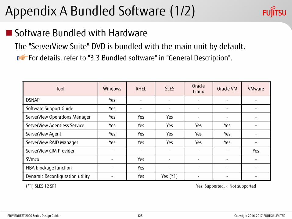
PRIMEQUEST 2000 Series Design Guide
Appendix A Bundled Software (1/2)
Software Bundled with Hardware The "ServerView Suite" DVD is bundled with the main unit by default.
For details, refer to "3.3 Bundled software" in "General Description".
Tool Windows RHEL SLES Oracle Linux
Oracle VM VMware
DSNAP Yes - - - - -
Software Support Guide Yes - - - - -
ServerView Operations Manager Yes Yes Yes - - -
ServerView Agentless Service Yes Yes Yes Yes Yes -
ServerView Agent Yes Yes Yes Yes Yes -
ServerView RAID Manager Yes Yes Yes Yes Yes -
ServerView CIM Provider - - - - - Yes
SVmco - Yes - - - -
HBA blockage function - Yes - - - -
Dynamic Reconfiguration utility - Yes Yes (*1) - - -
Yes: Supported, -: Not supported
Copyright 2016-2017 FUJITSU LIMITED
(*1) SLES 12 SP1
125

PRIMEQUEST 2000 Series Design Guide
Appendix A Bundled Software (2/2)
Drivers Windows
Drivers are provided with ServerView Suite.
For the latest versions, contact your sales representative.
Related Software Server Management Software
For details, refer to "1.5.3 Server management software" in "General Description".
Copyright 2016-2017 FUJITSU LIMITED 126

PRIMEQUEST 2000 Series Design Guide
Appendix B OS Specifications (1/8)
The following OS specification information is applied to the PRIMEQUEST 2000 series. For details on the specifications including maximum values on each OS, refer to the
information that is provided by each vendor. Windows Server 2012: Comparison of Specifications
Copyright 2016-2017 FUJITSU LIMITED
(*1) The upper limits of the file system size and the file size in each file system are as follows:
FAT Maximum size: 2TB, maximum file size: 2TB
NTFS Maximum size: 16TB (4KB cluster)/256TB (64KB cluster) (implementation restrictions, the logical maximum value is 16EB)
Maximum file size: 16TB (implementation restrictions, the logical maximum value is 2^64-1 clusters)
ReFS, which is the latest file system for Windows Server 2012, can be used for data areas, but ReFS is not recommended because its use has not been proven well.
OS type R2 Datacenter / R2 Standard Datacenter / Standard
CPU
Maximum number of sockets 8
Maximum number of cores 192
Maximum number of logical CPUs 384 (when Hyper-V is enabled)
320 (when Hyper-V is disabled)
Memory Maximum memory capacity 4TB
Disk (*1)
Number of partitions in a disk MBR format (Primary + Extended): 3+124, 4+0
GPT format: 128+0
Maximum LUN capacity MBR format: 2TB
GPT format: 256TB (Upper limit in the file system)
PCI Maximum number of PCI slots All slots can be used.
PCI Hot Plug PCI Box is supported. No IOU is supported. (Specification of the main unit)
Firmware UEFI support Supported
127
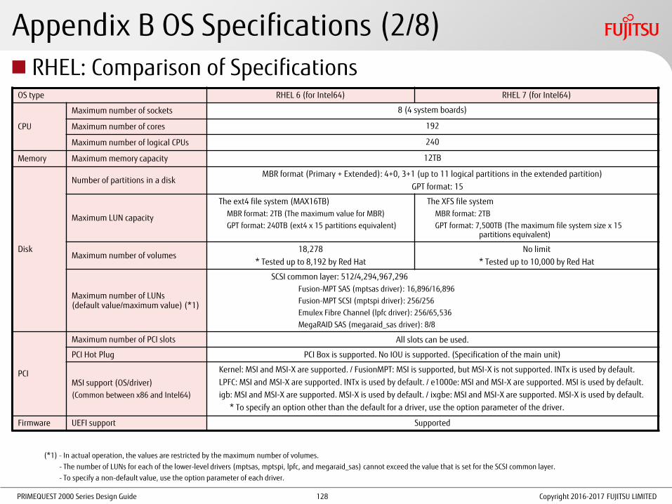
PRIMEQUEST 2000 Series Design Guide
Appendix B OS Specifications (2/8)
OS type RHEL 6 (for Intel64) RHEL 7 (for Intel64)
CPU
Maximum number of sockets 8 (4 system boards)
Maximum number of cores 192
Maximum number of logical CPUs 240
Memory Maximum memory capacity 12TB
Disk
Number of partitions in a disk MBR format (Primary + Extended): 4+0, 3+1 (up to 11 logical partitions in the extended partition)
GPT format: 15
Maximum LUN capacity
The ext4 file system (MAX16TB)
MBR format: 2TB (The maximum value for MBR)
GPT format: 240TB (ext4 x 15 partitions equivalent)
The XFS file system
MBR format: 2TB
GPT format: 7,500TB (The maximum file system size x 15 partitions equivalent)
Maximum number of volumes 18,278
* Tested up to 8,192 by Red Hat
No limit
* Tested up to 10,000 by Red Hat
Maximum number of LUNs (default value/maximum value) (*1)
SCSI common layer: 512/4,294,967,296
Fusion-MPT SAS (mptsas driver): 16,896/16,896
Fusion-MPT SCSI (mptspi driver): 256/256
Emulex Fibre Channel (lpfc driver): 256/65,536
MegaRAID SAS (megaraid_sas driver): 8/8
PCI
Maximum number of PCI slots All slots can be used.
PCI Hot Plug PCI Box is supported. No IOU is supported. (Specification of the main unit)
MSI support (OS/driver)
(Common between x86 and Intel64)
Kernel: MSI and MSI-X are supported. / FusionMPT: MSI is supported, but MSI-X is not supported. INTx is used by default.
LPFC: MSI and MSI-X are supported. INTx is used by default. / e1000e: MSI and MSI-X are supported. MSI is used by default.
igb: MSI and MSI-X are supported. MSI-X is used by default. / ixgbe: MSI and MSI-X are supported. MSI-X is used by default.
* To specify an option other than the default for a driver, use the option parameter of the driver.
Firmware UEFI support Supported
RHEL: Comparison of Specifications
(*1) - In actual operation, the values are restricted by the maximum number of volumes.
- The number of LUNs for each of the lower-level drivers (mptsas, mptspi, lpfc, and megaraid_sas) cannot exceed the value that is set for the SCSI common layer.
- To specify a non-default value, use the option parameter of each driver.
Copyright 2016-2017 FUJITSU LIMITED 128

PRIMEQUEST 2000 Series Design Guide Copyright 2016-2017 FUJITSU LIMITED
Appendix B OS Specifications (3/8)
SLES: Comparison of Specifications For details, refer to the following URLs:
SLES 11: https://www.suse.com/releasenotes/x86_64/SUSE-SLES/11/#rnotes-technical
SLES 12: https://www.suse.com/releasenotes/x86_64/SUSE-SLES/12/#TechInfo
OS type SLES 11 SP4 SLES 12 SP1
CPU Maximum number of logical CPUs 4,096 8,192
Memory Maximum memory capacity 24TB
Disk Maximum file system size 16TB (ext3) 1EB (ext4)
Maximum file size 2TB (ext3) 1EB (ext4)
PCI Maximum number of PCI slots All slots can be used.
PCI Hot Plug PCI Box is supported. No IOU is supported. (Specification of the main unit)
Firmware UEFI support Supported
129

PRIMEQUEST 2000 Series Design Guide Copyright 2016-2017 FUJITSU LIMITED
Appendix B OS Specifications (4/8)
Oracle Linux: Comparison of Specifications For details, refer to the following URL:
http://docs.oracle.com/cd/E52668_01/E67200/html/section-xv3-gvd-kn.html
OS type Oracle Linux 7 Update 2
CPU Maximum number of logical CPUs 2,048
Memory Maximum memory capacity 64TB
Disk
Maximum LUN capacity 50TB
Maximum file system size
bfrts: 50TB
ext4: 50TB
XFS: 500TB
Maximum file size
bfrts: 50TB
ext4: 50TB
XFS: 16TB
PCI Maximum number of PCI slots All slots can be used.
PCI Hot Plug Not supported
Firmware UEFI support Supported
130
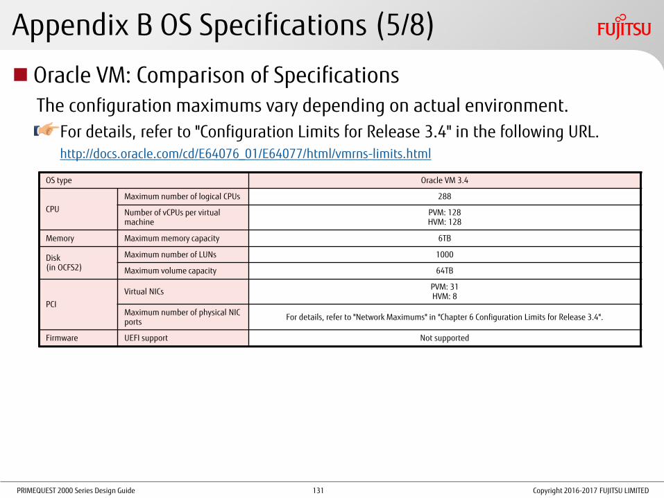
PRIMEQUEST 2000 Series Design Guide Copyright 2016-2017 FUJITSU LIMITED
Appendix B OS Specifications (5/8)
Oracle VM: Comparison of Specifications The configuration maximums vary depending on actual environment.
For details, refer to "Configuration Limits for Release 3.4" in the following URL. http://docs.oracle.com/cd/E64076_01/E64077/html/vmrns-limits.html
OS type Oracle VM 3.4
CPU
Maximum number of logical CPUs 288
Number of vCPUs per virtual machine
PVM: 128 HVM: 128
Memory Maximum memory capacity 6TB
Disk (in OCFS2)
Maximum number of LUNs 1000
Maximum volume capacity 64TB
PCI
Virtual NICs PVM: 31 HVM: 8
Maximum number of physical NIC ports
For details, refer to "Network Maximums" in "Chapter 6 Configuration Limits for Release 3.4".
Firmware UEFI support Not supported
131

PRIMEQUEST 2000 Series Design Guide
Appendix B OS Specifications (6/8)
Copyright 2016-2017 FUJITSU LIMITED
VMware vSphere 5.5: Comparison of Specifications The configuration maximums vary depending on actual environment.
For details, refer to "Configuration Maximums" in the following URL:
https://www.vmware.com/pdf/vsphere5/r55/vsphere-55-configuration-maximums.pdf
Edition of vSphere 5 Essentials Essentials Plus Standard Enterprise Enterprise Plus
CPU
Maximum number of logical CPUs
320
Number of vCPUs per virtual machine
64Way
Memory Maximum memory capacity 4TB
Disk (in VMFS)
Maximum number of LUNs 256
Maximum volume capacity 64TB
PCI
Maximum number of FC-HBAs 8
Maximum number of physical NIC ports
For details, refer to "Networking Maximums" in "Configuration Maximums".
Firmware UEFI support vSphere 5.5 GA/update1: Supported
vSphere 5.5 update2/update3: Not supported
Note: The number of LAN ports for the partition must include a port (1Gbps/1 port) for communication between the partition and the MMBs. In addition, make sure to include the number of onboard LAN ports (2 ports per IOU).
132

PRIMEQUEST 2000 Series Design Guide
Appendix B OS Specifications (7/8)
Copyright 2016-2017 FUJITSU LIMITED
VMware vSphere 6: Comparison of Specifications The configuration maximums vary depending on actual environment.
For details, refer to "Configuration Maximums" in the following URL:
https://www.vmware.com/pdf/vsphere6/r60/vsphere-60-configuration-maximums.pdf
Edition of vSphere 6 Essentials Essentials Plus Standard Enterprise Enterprise Plus
CPU
Maximum number of logical CPUs
480
Number of vCPUs per virtual machine
128Way
Memory Maximum memory capacity 6TB
Disk (in VMFS)
Maximum number of LUNs 256
Maximum volume capacity 64TB
PCI
Maximum number of FC-HBAs 8
Maximum number of physical NIC ports
For details, refer to "Networking Maximums" in "Configuration Maximums".
Firmware UEFI support Supported
Note: The number of LAN ports for the partition must include a port (1Gbps/1 port) for communication between the partition and the MMBs. In addition, make sure to include the number of onboard LAN ports (2 ports per IOU).
133

PRIMEQUEST 2000 Series Design Guide
Appendix B OS Specifications (8/8)
Copyright 2016-2017 FUJITSU LIMITED
VMware vSphere 6.5: Comparison of Specifications The configuration maximums vary depending on actual environment.
For details, refer to "Configuration Maximums" in the following URL:
https://www.vmware.com/pdf/vsphere6/r65/vsphere-65-configuration-maximums.pdf
Edition of vSphere 6 Essentials Essentials Plus Standard Enterprise Enterprise Plus
CPU
Maximum number of logical CPUs
576
Number of vCPUs per virtual machine
128Way
Memory Maximum memory capacity 12TB
Disk (in VMFS)
Maximum number of LUNs 512
Maximum volume capacity 64TB
PCI
Maximum number of FC-HBAs 8
Maximum number of physical NIC ports
For details, refer to "Networking Maximums" in "Configuration Maximums".
Firmware UEFI support Supported
Note: The number of LAN ports for the partition must include a port (1Gbps/1 port) for communication between the partition and the MMBs. In addition, make sure to include the number of onboard LAN ports (2 ports per IOU).
134

PRIMEQUEST 2000 Series Design Guide
Conditions of Use
Copyright, Trademark Rights, and Other Intellectual Property Rights The contents (text, images, audio, etc.) in this manual are protected by copyright, trademark rights, and other intellectual property rights. These contents may be printed and downloaded for personal use only. However, permission from Fujitsu Limited or the relevant right holder is required for any other use, such as reuse on your own website or uploading to another server.
Warranty Restrictions Fujitsu Limited does not guarantee the accuracy, merchantability, or applicability to your purpose of these contents, and shall bear no liability for any damages that are incurred as a result of the use of these contents. These contents are subject to change or removal without notice. For more information on this product or to contact us, refer to the following URL: http://www.fujitsu.com/global/about/resources/contact/computing/server/mission-critical/index.html
CA92344-0696-xx
All rights reserved.
Copyright 2016-2017 FUJITSU LIMITED 135

Copyright 2016-2017 FUJITSU LIMITED 136