Embed Size (px)
DESCRIPTION
Fujifilm Finepix-e550 Sm
Citation preview

THE COMPONENTS IDENTIFIED BY THE MARK “ ” ON THE SCHEMATICDIAGRAM AND IN THE PARTS LIST ARE CRITICAL FOR SAFETY.PLEASE REPLACE ONLY BY THE COMPONENTS SPECIFIED ON THE SCHEMATICDIAGRAM AND IN THE PARTS LIST.IF YOU USE PARTS NOT SPECIFIED, IT MAY RESULT IN A FIRE AND ANELECTRICAL SHOCK.
FUJI PHOTO FILM CO., LTD.Ref.No.: ZM00565-103
Printed in Japan 2005.10
DIGITAL CAMERA
FinePix E550
US/CA/EU/EG/GE/AS/CH/JP-ModelSERVICE MANUAL
WARNING
2
FinePix E550 Service Manual
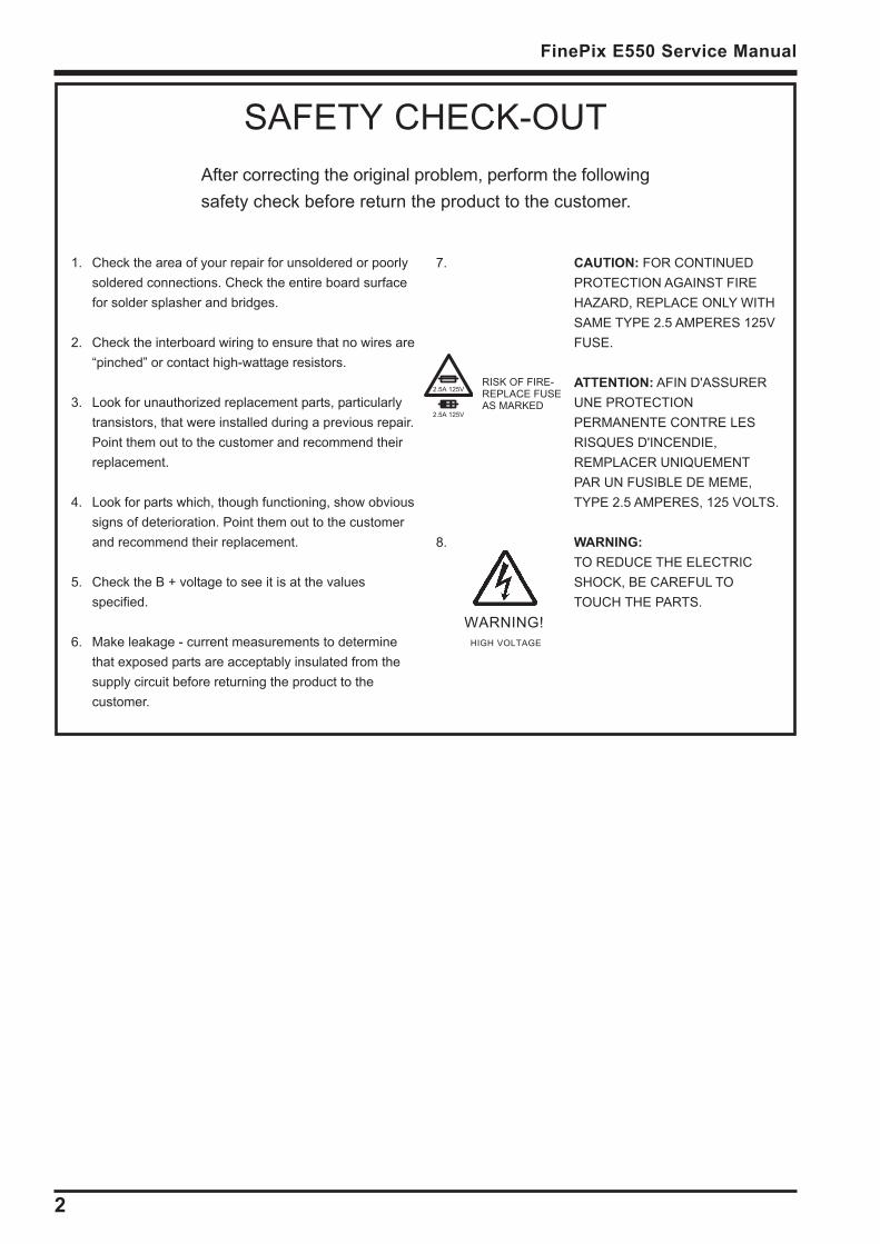
7. CAUTION: FOR CONTINUEDPROTECTION AGAINST FIREHAZARD, REPLACE ONLY WITHSAME TYPE 2.5 AMPERES 125VFUSE.
ATTENTION: AFIN D'ASSURERUNE PROTECTIONPERMANENTE CONTRE LESRISQUES D'INCENDIE,REMPLACER UNIQUEMENTPAR UN FUSIBLE DE MEME,TYPE 2.5 AMPERES, 125 VOLTS.
8. WARNING:TO REDUCE THE ELECTRICSHOCK, BE CAREFUL TOTOUCH THE PARTS.
WARNING! HIGH VOLTAGE
SAFETY CHECK-OUTAfter correcting the original problem, perform the followingsafety check before return the product to the customer.
1. Check the area of your repair for unsoldered or poorlysoldered connections. Check the entire board surfacefor solder splasher and bridges.
2. Check the interboard wiring to ensure that no wires are“pinched” or contact high-wattage resistors.
3. Look for unauthorized replacement parts, particularlytransistors, that were installed during a previous repair.Point them out to the customer and recommend theirreplacement.
4. Look for parts which, though functioning, show obvioussigns of deterioration. Point them out to the customerand recommend their replacement.
5. Check the B + voltage to see it is at the valuesspecified.
6. Make leakage - current measurements to determinethat exposed parts are acceptably insulated from thesupply circuit before returning the product to thecustomer.
2.5A 125V
2.5A 125V
RISK OF FIRE-REPLACE FUSEAS MARKED
3
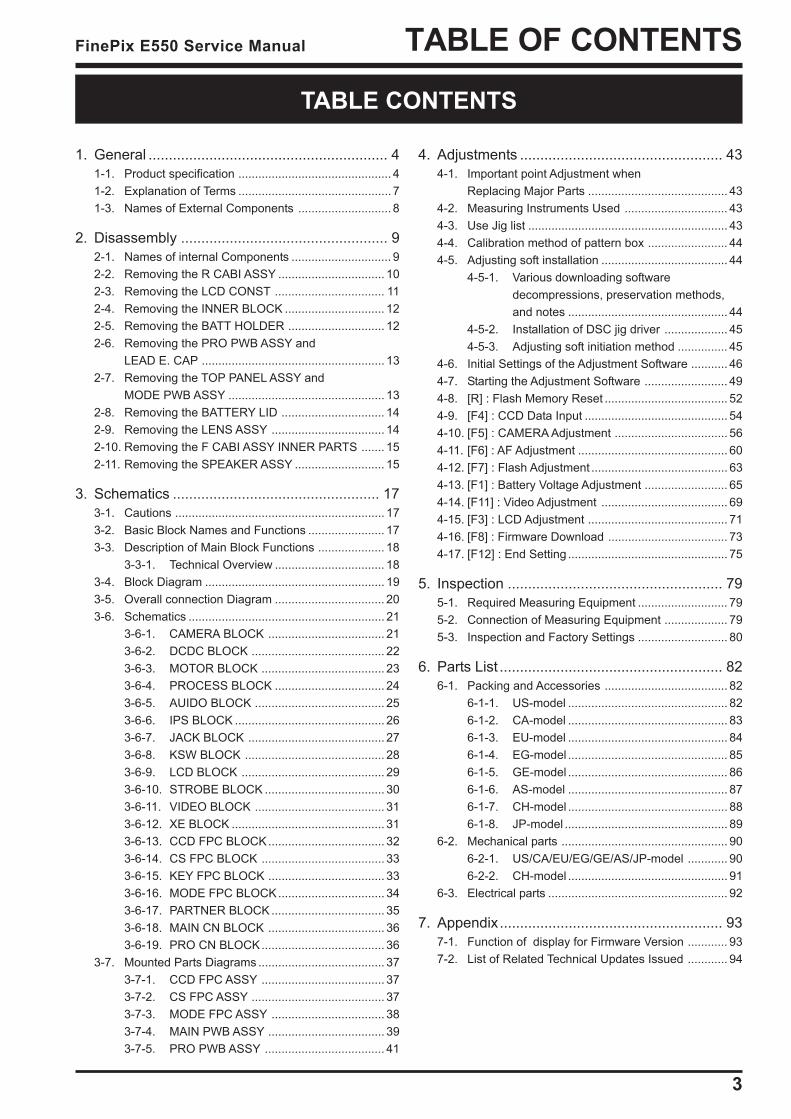
TABLE OF CONTENTSFinePix E550 Service Manual
TABLE CONTENTS
1. General ........................................................... 41-1. Product specification .............................................. 41-2. Explanation of Terms .............................................. 71-3. Names of External Components ............................ 8
2. Disassembly ................................................... 92-1. Names of internal Components .............................. 92-2. Removing the R CABI ASSY ................................ 102-3. Removing the LCD CONST ................................. 112-4. Removing the INNER BLOCK .............................. 122-5. Removing the BATT HOLDER ............................. 122-6. Removing the PRO PWB ASSY and
LEAD E. CAP ....................................................... 132-7. Removing the TOP PANEL ASSY and
MODE PWB ASSY ............................................... 132-8. Removing the BATTERY LID ............................... 142-9. Removing the LENS ASSY .................................. 142-10. Removing the F CABI ASSY INNER PARTS ....... 152-11. Removing the SPEAKER ASSY ........................... 15
3. Schematics ................................................... 173-1. Cautions ............................................................... 173-2. Basic Block Names and Functions ....................... 173-3. Description of Main Block Functions .................... 18
3-3-1. Technical Overview ................................. 183-4. Block Diagram ...................................................... 193-5. Overall connection Diagram ................................. 203-6. Schematics ........................................................... 21
3-6-1. CAMERA BLOCK ................................... 213-6-2. DCDC BLOCK ........................................ 223-6-3. MOTOR BLOCK ..................................... 233-6-4. PROCESS BLOCK ................................. 243-6-5. AUIDO BLOCK ....................................... 253-6-6. IPS BLOCK ............................................. 263-6-7. JACK BLOCK ......................................... 273-6-8. KSW BLOCK .......................................... 283-6-9. LCD BLOCK ........................................... 293-6-10. STROBE BLOCK .................................... 303-6-11. VIDEO BLOCK ....................................... 313-6-12. XE BLOCK .............................................. 313-6-13. CCD FPC BLOCK................................... 323-6-14. CS FPC BLOCK ..................................... 333-6-15. KEY FPC BLOCK ................................... 333-6-16. MODE FPC BLOCK................................ 343-6-17. PARTNER BLOCK .................................. 353-6-18. MAIN CN BLOCK ................................... 363-6-19. PRO CN BLOCK..................................... 36
3-7. Mounted Parts Diagrams ...................................... 373-7-1. CCD FPC ASSY ..................................... 373-7-2. CS FPC ASSY ........................................ 373-7-3. MODE FPC ASSY .................................. 383-7-4. MAIN PWB ASSY ................................... 393-7-5. PRO PWB ASSY .................................... 41
4. Adjustments .................................................. 434-1. Important point Adjustment when
Replacing Major Parts .......................................... 434-2. Measuring Instruments Used ............................... 434-3. Use Jig list ............................................................ 434-4. Calibration method of pattern box ........................ 444-5. Adjusting soft installation ...................................... 44
4-5-1. Various downloading softwaredecompressions, preservation methods,and notes ................................................ 44
4-5-2. Installation of DSC jig driver ................... 454-5-3. Adjusting soft initiation method ............... 45
4-6. Initial Settings of the Adjustment Software ........... 464-7. Starting the Adjustment Software ......................... 494-8. [R] : Flash Memory Reset ..................................... 524-9. [F4] : CCD Data Input ........................................... 544-10. [F5] : CAMERA Adjustment .................................. 564-11. [F6] : AF Adjustment ............................................. 604-12. [F7] : Flash Adjustment ......................................... 634-13. [F1] : Battery Voltage Adjustment ......................... 654-14. [F11] : Video Adjustment ...................................... 694-15. [F3] : LCD Adjustment .......................................... 714-16. [F8] : Firmware Download .................................... 734-17. [F12] : End Setting ................................................ 75
5. Inspection ..................................................... 795-1. Required Measuring Equipment ........................... 795-2. Connection of Measuring Equipment ................... 795-3. Inspection and Factory Settings ........................... 80
6. Parts List ....................................................... 826-1. Packing and Accessories ..................................... 82
6-1-1. US-model ................................................ 826-1-2. CA-model ................................................ 836-1-3. EU-model ................................................ 846-1-4. EG-model ................................................ 856-1-5. GE-model ................................................ 866-1-6. AS-model ................................................ 876-1-7. CH-model ................................................ 886-1-8. JP-model ................................................. 89
6-2. Mechanical parts .................................................. 906-2-1. US/CA/EU/EG/GE/AS/JP-model ............ 906-2-2. CH-model ................................................ 91
6-3. Electrical parts ...................................................... 92
7. Appendix....................................................... 937-1. Function of display for Firmware Version ............ 937-2. List of Related Technical Updates Issued ............ 94
4
1. General FinePix E550 Service Manual
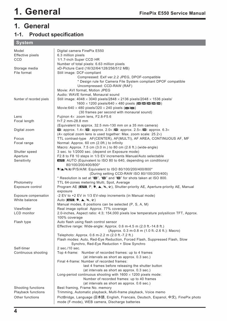
SystemModel Digital camera FinePix E550Effective pixels 6.3 million pixelsCCD 1/1.7-inch Super CCD HR
Number of total pixels: 6.63 million pixelsStorage media xD-Picture Card (16/32/64/128/256/512 MB)File format Still image: DCF-compliant
Compressed: Exif ver.2.2 JPEG, DPOF-compatible * Design rule for Camera File System compliant DPOF compatible Uncompressed: CCD-RAW (RAF)
Movie: AVI format, Motion JPEGAudio: WAVE format, Monaural sound
Number of recorded pixels Still image: 4048 × 3040 pixels/2848 × 2136 pixels/2048 × 1536 pixels/ 1600 × 1200 pixels/640 × 480 pixels ( / / / / )Movie:640 × 480 pixels/320 × 240 pixels ( / )
(30 frames per second with monaural sound)Lens Fujinon 4× zoom lens, F2.8-F5.6Focal length f=7.2 mm-28.8 mm
(Equivalent to approx. 32.5 mm-130 mm on a 35 mm camera)Digital zoom : approx. 1.4× / : approx. 2.0× / : approx. 2.5× / : approx. 6.3×
(4× optical zoom lens is used together: Max. zoom scale: 25.2×)Focus TTL contrast-type AF(CENTER), AF(MULTI), AF AREA, CONTINUOUS AF, MFFocal range Normal: Approx. 60 cm (2.0ft.) to infinity
Macro: Approx. 7.5 cm (3.0 in.) to 80 cm (2.6 ft.) (wide-angle)Shutter speed 3 sec. to 1/2000 sec. (depend on Exposure mode)Aperture F2.8 to F8 10 steps in 1/3 EV increments Manual/Auto selectableSensitivity : AUTO (Equivalent to ISO 80 to 640, depending on conditions)/
80/100/200/400/800*/ / / /P/S/A/M: Equivalent to ISO 80/100/200/400/800*
(During setting CCD-RAW ISO 80/100/200/400)* Resolution is set at “ ”, “ ” and “ ” for shots taken at ISO 800.
Photometry TTL 64-zones metering Multi, Spot, AverageExposure control Program AE ( , P, , , , ), Shutter-priority AE, Aperture-priority AE, Manual
exposureExposure compensation -2 EV to +2 EV in 1/3 EV-step increments (in Manual mode)White balance Auto ( , , , , )
Manual modes, 8 positions can be selected (P, S, A, M)Viewfinder Real image optical Approx. 77% coverageLCD monitor 2.0-inches, Aspect ratio: 4:3; 154,000 pixels low temperature polysilicon TFT, Approx.
100% coverageFlash type Auto flash using flash control sensor
Effective range: Wide-angle: Approx. 0.6 m-4.5 m (2.0 ft.-14.8 ft.) (Approx. 0.3 m-0.8 m (1.0 ft.-2.6 ft.): Macro)
Telephoto: Approx. 0.6 m-2.2 m (2.0 ft.-7.2 ft.)Flash modes: Auto, Red-Eye Reduction, Forced Flash, Suppressed Flash, Slow
Synchro, Red-Eye Reduction + Slow SynchroSelf-timer 2 sec./10 sec.Continuous shooting Top 4-frame: Number of recorded frames: up to 4 frames
(at intervals as short as approx. 0.3 sec.)Final 4-frame: Number of recorded frames:
last 4 frames before releasing the shutter button (at intervals as short as approx. 0.3 sec.)
Long-period continuous shooting with 1600 × 1200 pixels mode: Number of recorded frames: up to 40 frames (at intervals as short as approx. 0.6 sec.)
Shooting functions Best framing, Frame No. memoryPlayback functions Trimming, Automatic playback, Multi-frame playback, Voice memoOther functions PictBridge, Language ( , English, Francais, Deutsch, Espanol, ), FinePix photo
mode (F-mode), WEB camera, Discharge batteries
1. General1-1. Product specification
5
1. GeneralFinePix E550 Service Manual
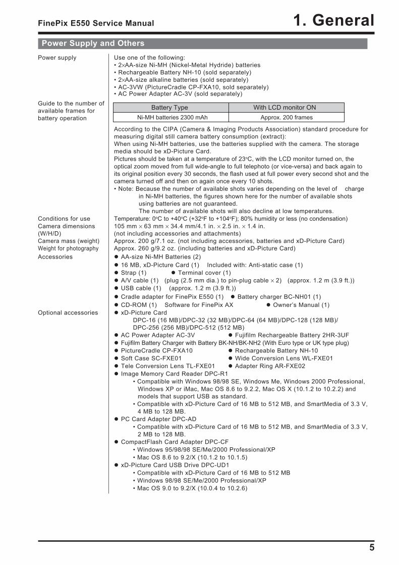
Power Supply and OthersPower supply Use one of the following:
• 2×AA-size Ni-MH (Nickel-Metal Hydride) batteries• Rechargeable Battery NH-10 (sold separately)• 2×AA-size alkaline batteries (sold separately)• AC-3VW (PictureCradle CP-FXA10, sold separately)• AC Power Adapter AC-3V (sold separately)
According to the CIPA (Camera & Imaging Products Association) standard procedure formeasuring digital still camera battery consumption (extract):When using Ni-MH batteries, use the batteries supplied with the camera. The storagemedia should be xD-Picture Card.Pictures should be taken at a temperature of 23oC, with the LCD monitor turned on, theoptical zoom moved from full wide-angle to full telephoto (or vice-versa) and back again toits original position every 30 seconds, the flash used at full power every second shot and thecamera turned off and then on again once every 10 shots.• Note: Because the number of available shots varies depending on the level of charge
in Ni-MH batteries, the figures shown here for the number of available shotsusing batteries are not guaranteed.
The number of available shots will also decline at low temperatures.Conditions for use Temperature: 0oC to +40oC (+32oF to +104oF); 80% humidity or less (no condensation)Camera dimensions 105 mm × 63 mm × 34.4 mm/4.1 in. × 2.5 in. × 1.4 in.(W/H/D) (not including accessories and attachments)Camera mass (weight) Approx. 200 g/7.1 oz. (not including accessories, batteries and xD-Picture Card)Weight for photography Approx. 260 g/9.2 oz. (including batteries and xD-Picture Card)Accessories AA-size Ni-MH Batteries (2)
16 MB, xD-Picture Card (1) Included with: Anti-static case (1) Strap (1) Terminal cover (1) A/V cable (1) (plug (2.5 mm dia.) to pin-plug cable × 2) (approx. 1.2 m (3.9 ft.)) USB cable (1) (approx. 1.2 m (3.9 ft.)) Cradle adapter for FinePix E550 (1) Battery charger BC-NH01 (1) CD-ROM (1) Software for FinePix AX Owner’s Manual (1)
Optional accessories xD-Picture CardDPC-16 (16 MB)/DPC-32 (32 MB)/DPC-64 (64 MB)/DPC-128 (128 MB)/DPC-256 (256 MB)/DPC-512 (512 MB)
AC Power Adapter AC-3V Fujifilm Rechargeable Battery 2HR-3UF Fujifilm Battery Charger with Battery BK-NH/BK-NH2 (With Euro type or UK type plug) PictureCradle CP-FXA10 Rechargeable Battery NH-10 Soft Case SC-FXE01 Wide Conversion Lens WL-FXE01 Tele Conversion Lens TL-FXE01 Adapter Ring AR-FXE02 Image Memory Card Reader DPC-R1
• Compatible with Windows 98/98 SE, Windows Me, Windows 2000 Professional,Windows XP or iMac, Mac OS 8.6 to 9.2.2, Mac OS X (10.1.2 to 10.2.2) andmodels that support USB as standard.
• Compatible with xD-Picture Card of 16 MB to 512 MB, and SmartMedia of 3.3 V,4 MB to 128 MB.
PC Card Adapter DPC-AD• Compatible with xD-Picture Card of 16 MB to 512 MB, and SmartMedia of 3.3 V,
2 MB to 128 MB. CompactFlash Card Adapter DPC-CF
• Windows 95/98/98 SE/Me/2000 Professional/XP• Mac OS 8.6 to 9.2/X (10.1.2 to 10.1.5)
xD-Picture Card USB Drive DPC-UD1• Compatible with xD-Picture Card of 16 MB to 512 MB• Windows 98/98 SE/Me/2000 Professional/XP• Mac OS 9.0 to 9.2/X (10.0.4 to 10.2.6)
Guide to the number ofavailable frames forbattery operation Ni-MH batteries 2300 mAh Approx. 200 frames
Battery Type With LCD monitor ON

6
1. General FinePix E550 Service Manual
Input/Output TerminalsA/V OUT (Audio/Visual output) 2.5 mm dia. jacksocket
(USB) socket For file transfer to a computer and connection to the optional cradleDC input Socket for specified AC power adapter AC-3V (sold separately)
Connection for the AC Power Adapter AC-3VW bundled with the cradle (sold separately)
Standard number of available frames/recording time per xD-Picture CardThe number of available frames, recording time or file size varies slightly depending on the subjects photographed. Note alsothat the divergence between standard number of frames and the actual number of frames is greater for xD-Picture Cards with higher capacities.
Quality setting
DPC-16 (16 MB)
DPC-32 (32 MB)
DPC-64 (64 MB)
DPC-128 (128 MB)
DPC-256 (256 MB)
Image data size
Number of recorded pixels
F
4048 3040 2848 2136 2048 1536 1600 1200 640 480 4048 3040 640 480 320 240
N (30 fps) (30 fps)
3
6
12
26
52
4.9MB
DPC-512 (512 MB) 105
6
12
26
52
105
2.5MB
211
10
20
42
84
169
1.5MB
339
19
40
81
162
325
780KB
651
25
50
101
204
409
630KB
818
122
247
497
997
1997
125KB
3993
1
2
4
9
19
13MB
39
18 sec.
36 sec.
73 sec.
147 sec.
296 sec.
9.8 min.
26 sec.
54 sec.
109 sec.
219 sec.
7.3 min.
14.6 min.
7
1. GeneralFinePix E550 Service Manual
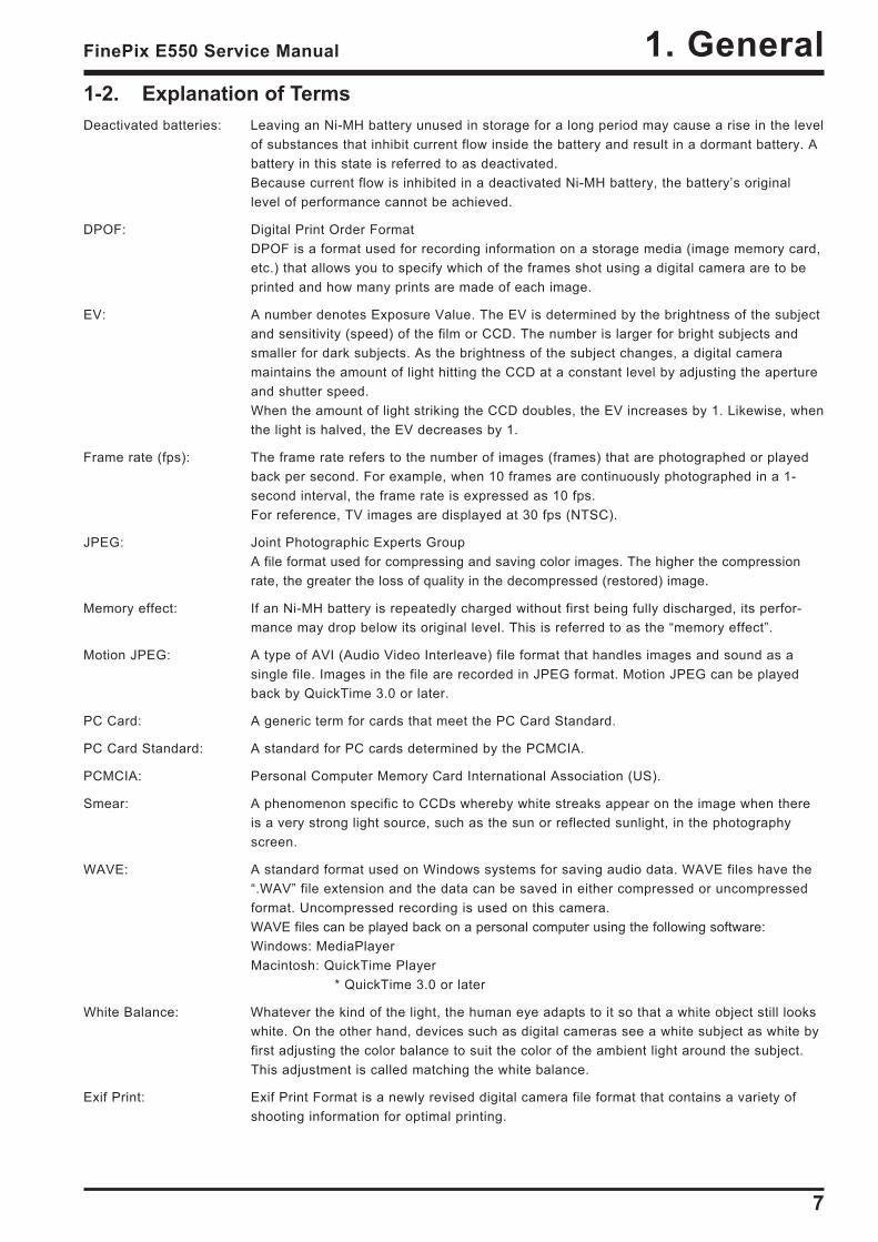
1-2. Explanation of TermsDeactivated batteries: Leaving an Ni-MH battery unused in storage for a long period may cause a rise in the level
of substances that inhibit current flow inside the battery and result in a dormant battery. Abattery in this state is referred to as deactivated.Because current flow is inhibited in a deactivated Ni-MH battery, the battery’s originallevel of performance cannot be achieved.
DPOF: Digital Print Order FormatDPOF is a format used for recording information on a storage media (image memory card,etc.) that allows you to specify which of the frames shot using a digital camera are to beprinted and how many prints are made of each image.
EV: A number denotes Exposure Value. The EV is determined by the brightness of the subjectand sensitivity (speed) of the film or CCD. The number is larger for bright subjects andsmaller for dark subjects. As the brightness of the subject changes, a digital cameramaintains the amount of light hitting the CCD at a constant level by adjusting the apertureand shutter speed.When the amount of light striking the CCD doubles, the EV increases by 1. Likewise, whenthe light is halved, the EV decreases by 1.
Frame rate (fps): The frame rate refers to the number of images (frames) that are photographed or playedback per second. For example, when 10 frames are continuously photographed in a 1-second interval, the frame rate is expressed as 10 fps.For reference, TV images are displayed at 30 fps (NTSC).
JPEG: Joint Photographic Experts GroupA file format used for compressing and saving color images. The higher the compressionrate, the greater the loss of quality in the decompressed (restored) image.
Memory effect: If an Ni-MH battery is repeatedly charged without first being fully discharged, its perfor-mance may drop below its original level. This is referred to as the “memory effect”.
Motion JPEG: A type of AVI (Audio Video Interleave) file format that handles images and sound as asingle file. Images in the file are recorded in JPEG format. Motion JPEG can be playedback by QuickTime 3.0 or later.
PC Card: A generic term for cards that meet the PC Card Standard.
PC Card Standard: A standard for PC cards determined by the PCMCIA.
PCMCIA: Personal Computer Memory Card International Association (US).
Smear: A phenomenon specific to CCDs whereby white streaks appear on the image when thereis a very strong light source, such as the sun or reflected sunlight, in the photographyscreen.
WAVE: A standard format used on Windows systems for saving audio data. WAVE files have the“.WAV” file extension and the data can be saved in either compressed or uncompressedformat. Uncompressed recording is used on this camera.WAVE files can be played back on a personal computer using the following software:Windows: MediaPlayerMacintosh: QuickTime Player
* QuickTime 3.0 or later
White Balance: Whatever the kind of the light, the human eye adapts to it so that a white object still lookswhite. On the other hand, devices such as digital cameras see a white subject as white byfirst adjusting the color balance to suit the color of the ambient light around the subject.This adjustment is called matching the white balance.
Exif Print: Exif Print Format is a newly revised digital camera file format that contains a variety ofshooting information for optimal printing.

8
1. General FinePix E550 Service Manual
1-3. Names of External Components
Flash control sensor
Flash
Speaker
Microphone
Viewfinder window
Adapter ring release button
Shutter button
Mode dial
Self-timer lamp
Lens (Lens cover)
DC IN 3V (Power input) socket
USB socket
Cradle connection socket
A/V OUT (Audio / Visual output) socket
POWER button
Terminal cover
Flash pop-up button
(Wide zoom) button
Mode switch
BACK button
DISP (Display) button
Battery cover
Battery cover lock release button
MENU/OK button
4-direction ( ) button
(Tele zoom) button
Strap mount
Viewfinder lamp
Viewfinder
Exposure compensation button
Tripod mount
LCD monitor
xD-Picture Card slot
Battery compartment
Photo mode ( ) button
/ (Macro) button
/ (Flash) button
9
2. DisassemblyFinePix E550 Service Manual
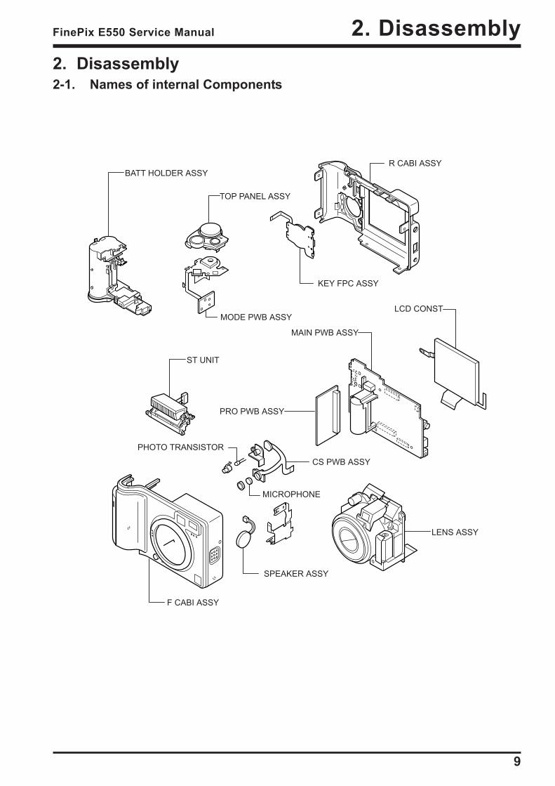
2. Disassembly2-1. Names of internal Components
R CABI ASSY
TOP PANEL ASSY
KEY FPC ASSY
MODE PWB ASSY
BATT HOLDER ASSY
F CABI ASSY
SPEAKER ASSY
CS PWB ASSY
MICROPHONE
PHOTO TRANSISTOR
ST UNIT
LENS ASSY
LCD CONST
MAIN PWB ASSY
PRO PWB ASSY
10
2. Disassembly FinePix E550 Service Manual
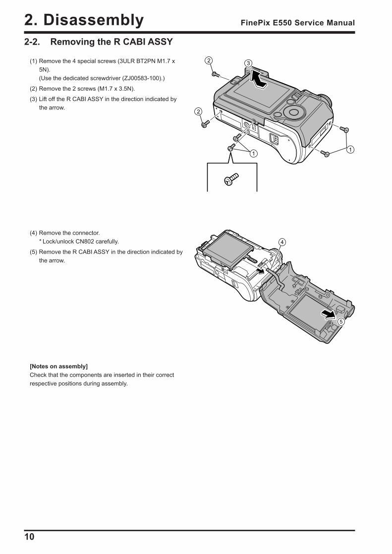
2-2. Removing the R CABI ASSY
(1) Remove the 4 special screws (3ULR BT2PN M1.7 x5N).(Use the dedicated screwdriver (ZJ00583-100).)
(2) Remove the 2 screws (M1.7 x 3.5N).
(3) Lift off the R CABI ASSY in the direction indicated bythe arrow.
(4) Remove the connector.* Lock/unlock CN802 carefully.
(5) Remove the R CABI ASSY in the direction indicated bythe arrow.
[Notes on assembly]Check that the components are inserted in their correctrespective positions during assembly.
2
11
2
3
4
5
11
2. DisassemblyFinePix E550 Service Manual
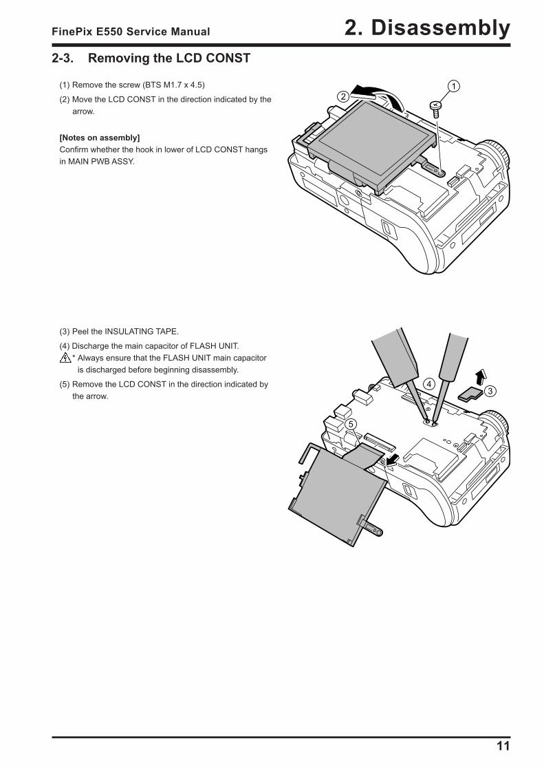
2-3. Removing the LCD CONST
(1) Remove the screw (BTS M1.7 x 4.5)
(2) Move the LCD CONST in the direction indicated by thearrow.
[Notes on assembly]Confirm whether the hook in lower of LCD CONST hangsin MAIN PWB ASSY.
(3) Peel the INSULATING TAPE.
(4) Discharge the main capacitor of FLASH UNIT.* Always ensure that the FLASH UNIT main capacitor
is discharged before beginning disassembly.
(5) Remove the LCD CONST in the direction indicated bythe arrow.
12
4
5
3
12
2. Disassembly FinePix E550 Service Manual
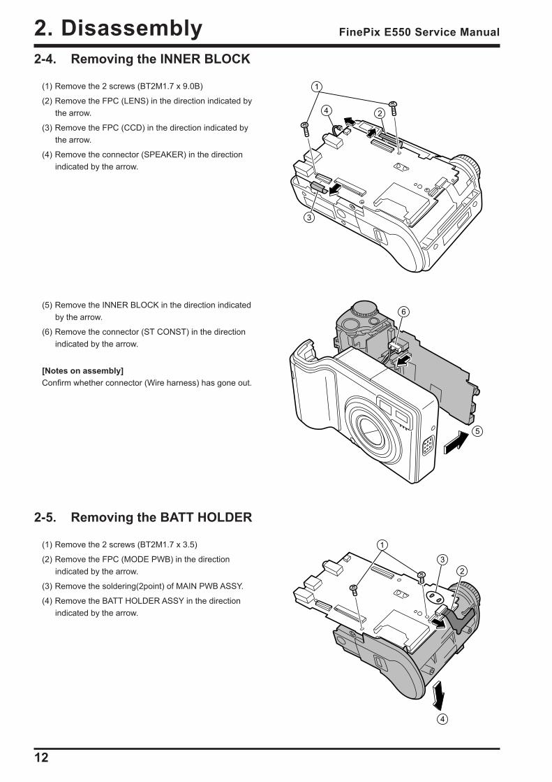
2-4. Removing the INNER BLOCK
(1) Remove the 2 screws (BT2M1.7 x 9.0B)
(2) Remove the FPC (LENS) in the direction indicated bythe arrow.
(3) Remove the FPC (CCD) in the direction indicated bythe arrow.
(4) Remove the connector (SPEAKER) in the directionindicated by the arrow.
2-5. Removing the BATT HOLDER
(1) Remove the 2 screws (BT2M1.7 x 3.5)
(2) Remove the FPC (MODE PWB) in the directionindicated by the arrow.
(3) Remove the soldering(2point) of MAIN PWB ASSY.
(4) Remove the BATT HOLDER ASSY in the directionindicated by the arrow.
(5) Remove the INNER BLOCK in the direction indicatedby the arrow.
(6) Remove the connector (ST CONST) in the directionindicated by the arrow.
[Notes on assembly]Confirm whether connector (Wire harness) has gone out.
1
4
3
2
5
6
4
32
1

13
2. DisassemblyFinePix E550 Service Manual
2-7. Removing the TOP PANEL ASSY and MODE PWB ASSY
(1) Remove the EMI SHEET A in the direction indicated bythe arrow.
(2) Remove the screw (M1.7 x 3.0)
(3) Remove the FPC(MODE PWB)in the directionindicated by the arrow.
2-6. Removing the PRO PWB ASSY and LEAD E. CAP
(1) Remove the PRO PWB ASSY in the direction indicatedby the arrow.
(2) Remove the soldering(2point) of MAIN PWB ASSY.
(3) Remove the LEAD E CAPin the direction indicated bythe arrow.
(4) Remove Hook in the direction indicated by the arrow.
(5) Remove CONDENSER HOLDER in the directionindicated by the arrow.
[Assembly]To assemble, use the disassembly procedure in reverse.
1
2
3
4
5
1
2
3
4
5(4) Remove the FPC(MODE PWB) in the directionindicated by the arrow.
(5) Remove theMODE PWB ASSY in the directionindicated by the arrow.
[Assembly]Do not insert it diagonally when you assemble it.
14
2. Disassembly FinePix E550 Service Manual
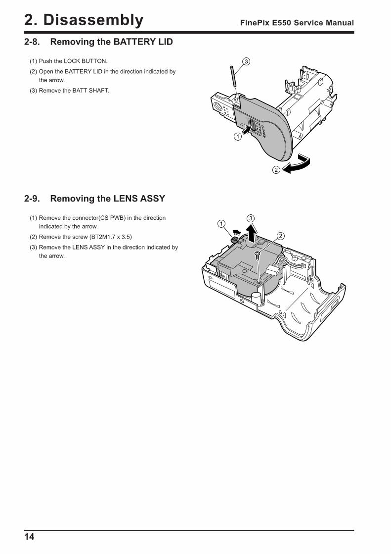
2-8. Removing the BATTERY LID
(1) Push the LOCK BUTTON.
(2) Open the BATTERY LID in the direction indicated bythe arrow.
(3) Remove the BATT SHAFT.
2-9. Removing the LENS ASSY
(1) Remove the connector(CS PWB) in the directionindicated by the arrow.
(2) Remove the screw (BT2M1.7 x 3.5)
(3) Remove the LENS ASSY in the direction indicated bythe arrow.
1
2
3
1
2
3
15
2. DisassemblyFinePix E550 Service Manual
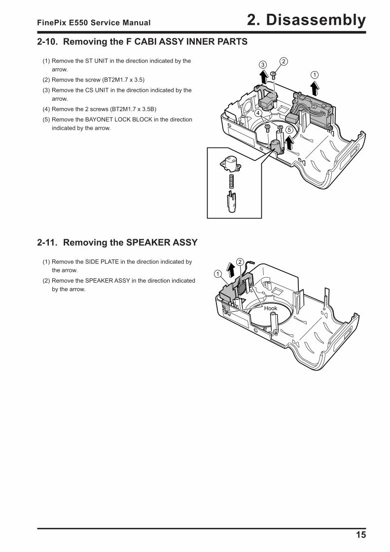
2-11. Removing the SPEAKER ASSY
(1) Remove the SIDE PLATE in the direction indicated bythe arrow.
(2) Remove the SPEAKER ASSY in the direction indicatedby the arrow.
1
2
Hook
1
23
5
4
2-10. Removing the F CABI ASSY INNER PARTS
(1) Remove the ST UNIT in the direction indicated by thearrow.
(2) Remove the screw (BT2M1.7 x 3.5)
(3) Remove the CS UNIT in the direction indicated by thearrow.
(4) Remove the 2 screws (BT2M1.7 x 3.5B)
(5) Remove the BAYONET LOCK BLOCK in the directionindicated by the arrow.

16
2. Disassembly FinePix E550 Service Manual
MEMO
17
3. SchematicsFinePix E550 Service Manual
3. Schematics3-1. Cautions
<Cautions when replacing parts>• Do not reuse removed parts. Always use new parts.
• Note that the negative side of tantalum condensers is readily damaged by heat.
• Except for chemical condensers and tantalum condensers, voltage is not displayed on condensers with a voltageresistance of 50V or less.
• Resistors not marked are 1/16W chip resistors.
• KΩ = 1000Ω, MΩ = 1000KΩ
• B characteristics of variable resistors and semi-fixed resistors are not displayed.
3-2. Basic Block Names and Functions
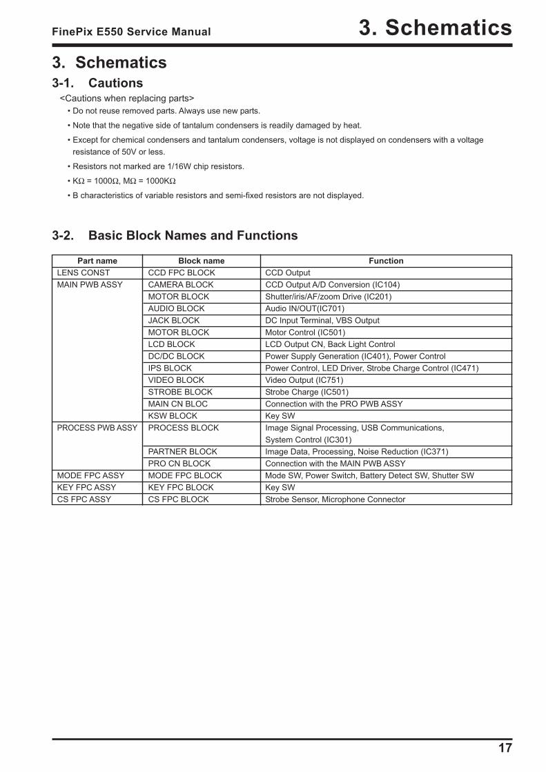
Part name Block name FunctionLENS CONST CCD FPC BLOCK CCD OutputMAIN PWB ASSY CAMERA BLOCK CCD Output A/D Conversion (IC104)
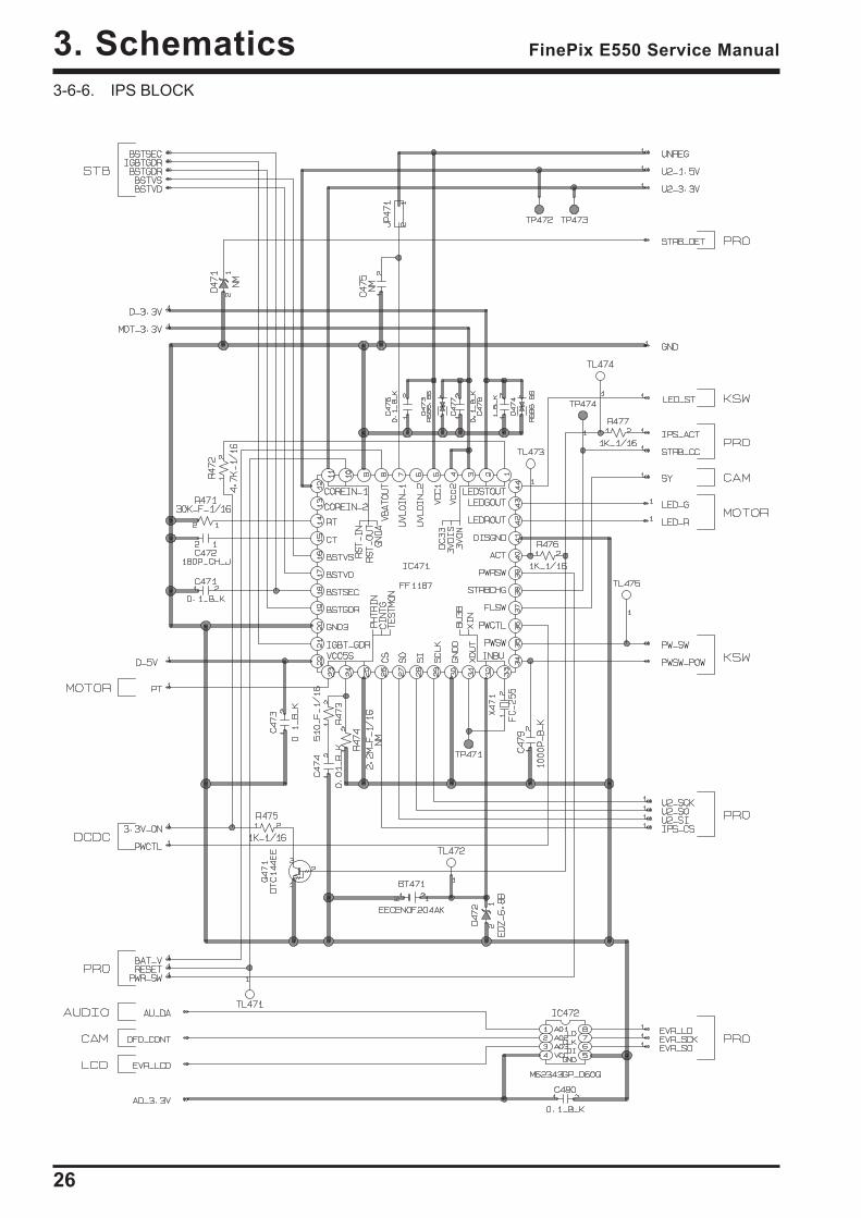
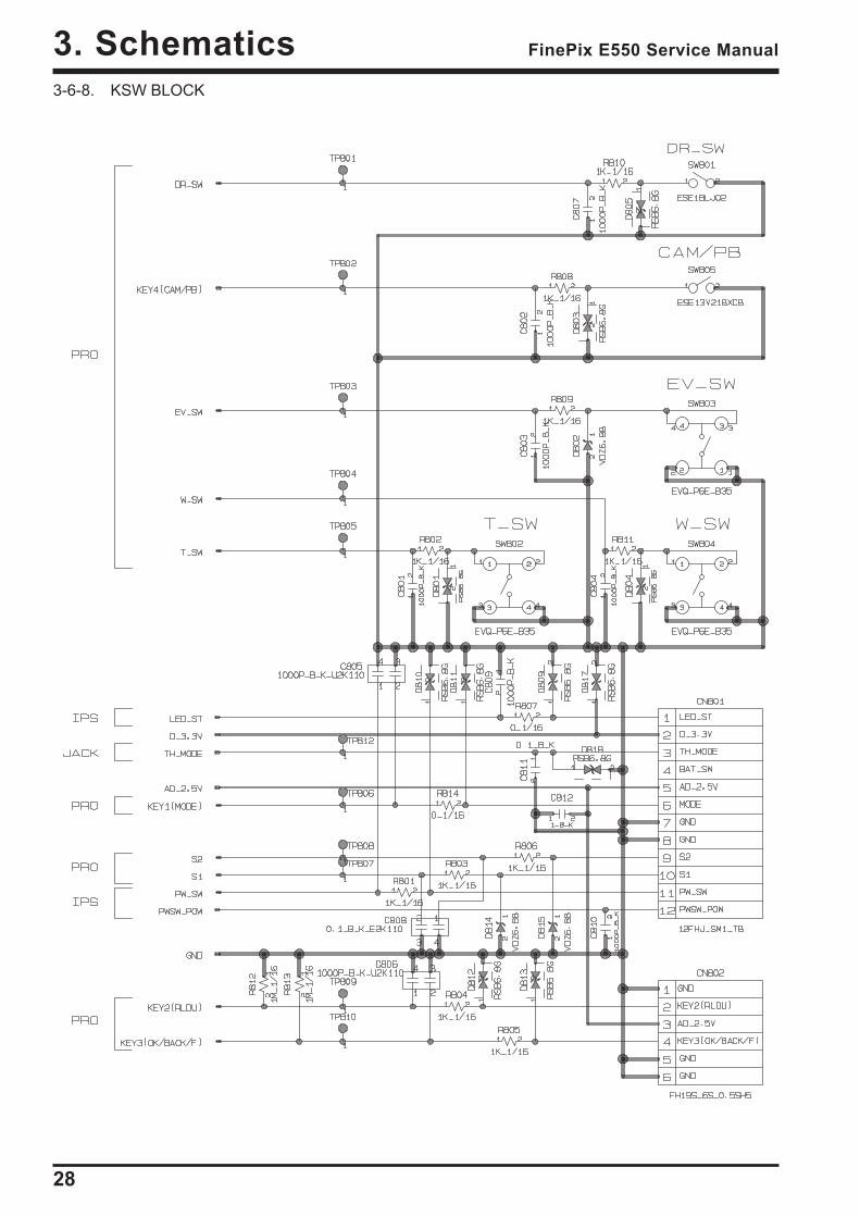
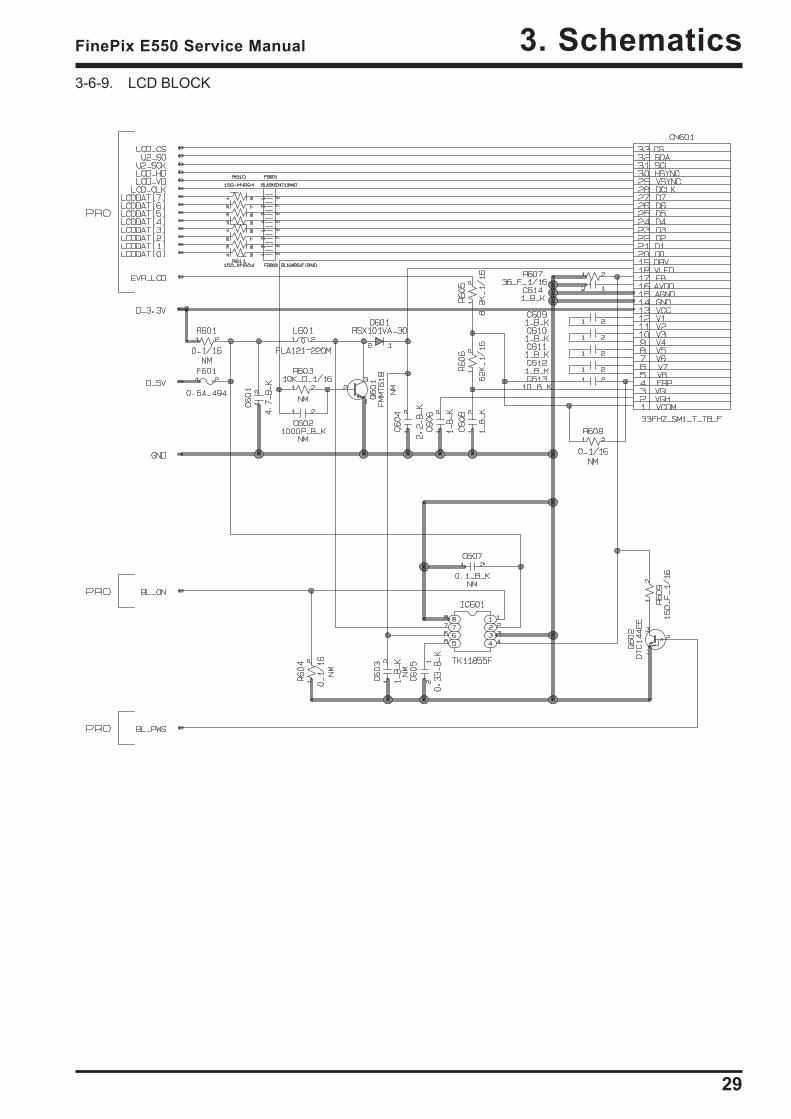
MOTOR BLOCK Shutter/iris/AF/zoom Drive (IC201)AUDIO BLOCK Audio IN/OUT(IC701)JACK BLOCK DC Input Terminal, VBS OutputMOTOR BLOCK Motor Control (IC501)LCD BLOCK LCD Output CN, Back Light ControlDC/DC BLOCK Power Supply Generation (IC401), Power ControlIPS BLOCK Power Control, LED Driver, Strobe Charge Control (IC471)VIDEO BLOCK Video Output (IC751)STROBE BLOCK Strobe Charge (IC501)MAIN CN BLOC Connection with the PRO PWB ASSYKSW BLOCK Key SW
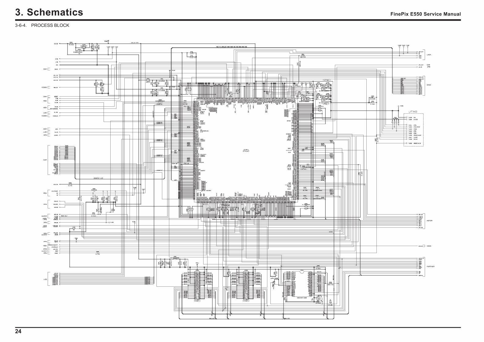
PROCESS PWB ASSY PROCESS BLOCK Image Signal Processing, USB Communications,System Control (IC301)
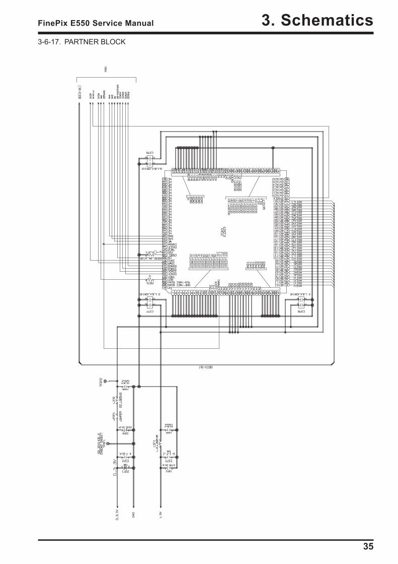
PARTNER BLOCK Image Data, Processing, Noise Reduction (IC371)PRO CN BLOCK Connection with the MAIN PWB ASSY
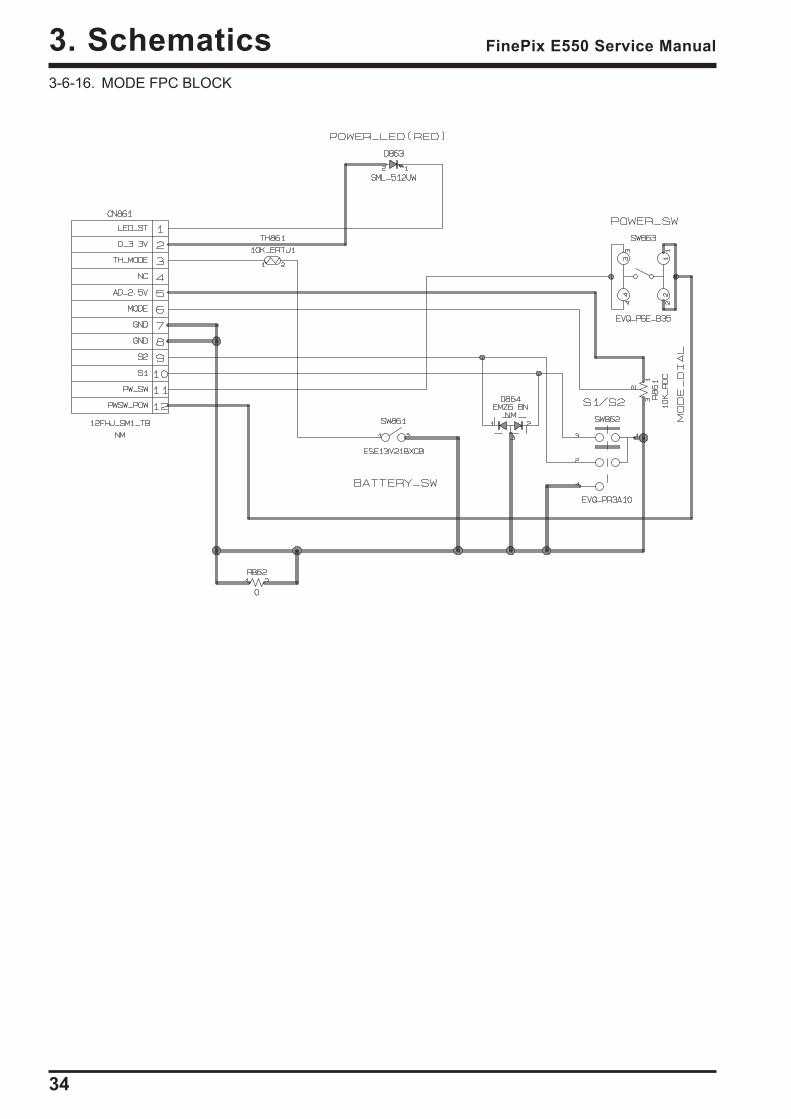
MODE FPC ASSY MODE FPC BLOCK Mode SW, Power Switch, Battery Detect SW, Shutter SWKEY FPC ASSY KEY FPC BLOCK Key SWCS FPC ASSY CS FPC BLOCK Strobe Sensor, Microphone Connector
18
3. Schematics FinePix E550 Service Manual
3-3. Description of Main Block Functions3-3-1. Technical OverviewCCD signal processing/Camera circuit section
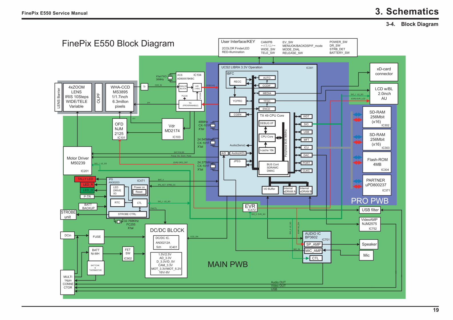
Analog signals output from the 1/1.7 type Super-CCD Honeycom IV HR (IC151), with an effective pixel count of 6.3mega-pixels, undergo false color compensation processing, adaptive interpolation processing, amplification (AGC) andsignal mixing inside the CCD signal processing IC “ACS (IC104)” before being converted to 14-bit digital signals (A/D)and sent to the signal processing LSI “UCS2 (IC301)”.The vertical drive IC (IC103) for driving the CCD and the OFD voltage control IC (IC101) are in this block.
Motor Circuit SectionThe signal processing LSI “UCS2 (IC301)” that has received various operating switch commands manages the motordrive IC (IC201) and controls the AF, SHUTTER, ZOOM and IRIS motors.
Imaging and Signal Processing SectionInput data from the CCD14-bit digital image data (corresponding to 1H) that has been output from the imaging section (CCD/Camera Block) issent to the signal processing LSI “UCS2 (IC301)”, converted to 32-bit (16-bit x 2) data by the [internal buffer] inside thisLSI, and the image data for one frame (4048 x 3040 pix) is stored temporarily in [SD-RAM]. It is also integrated in the[AUTO operation section] using the 32-bit the signal processing LSI “UCS2 (IC301)” image data and sent to the ACS_IC(IC104) to obtain the appropriate AE/AF/AWB.Record processing to xD CardImage data stored in SD-DRAM “IC302/303” is sent one frame at a time to the internal [signal processing section] in thesignal processing LSI “UCS2 (IC301)”. In a process called unpacking, “32-bit to 12-bit conversion” and “pre-processingincluding digital clamp, white balance and noise reduction processing, linear matrix processing, gamma correction and R/G/B 14-bit to R/G/B 8-bit conversion” to “8-bit digital R/G/B signals to Y:Cb:Cr = 4:2:2 YC processing” are implemented inthis [signal processing section] and 8-bit Y/Cb/Cr image data are sent to the [internal buffer].* Noise reduction processing, linear matrix processing and gamma correction included here are processed by the Partner
chip.The “rearrangement of data in a format in which 8-bit Y/Cb/Cr signals are easily compressed” is done in the [internalbuffer] and after passing through the [JPEG operation block] to the [media controller], they are recorded on the xD card.Reproduction of images from xD cardCompressed image data from the xD card is sent as 8-bit image data to the signal processing LSI “UCS2 (IC301)” then itis sent to the [media control section], the [DMA unit] and the SD-DRAM “IC302/303” and then it is sent to the [mediacontroller], to the [JPEG operation section] and to the [signal processing section].In the [signal processing section], 8-bit Y/Cb/Cr signals are converted to 8-bit R/G/B signals and at the same time,lettering display signals are weighted and passed through the [LCD controller to the LCD unit and displayed.Image capture system adjustment data are stored in the Flash ROM (IC304).
LCD UnitDigital signals sent from the signal processing LSI “UCS2 (IC301)” are sent directly to the LCD.
Power Supply SectionPower supply circuits constructed in the core of the DC IC (IC401) create the following power supplies, which aresupplied to each block.D3.3V [IC201 (MOTOR BLOCK), IC302/IC303 (SDRAM), IC301 (UCS2), IC472(DAL), IC304 (Flash Rom), IC371
(PARTNER), IC471 (IPS), LCD (CN501), MODE FPC, USB (CN901)]D5V [IC103 (V_Drv), C401 (DCDC BLOCK), IC471 (IPS)]-8V [IC151 (CCD), IC103 (V_Drv)]15V [IC151 (CCD), IC103 (V_Drv), IC101 (OFD_Drv)]CAM3.3V [IC104 (ACS)]1.5V [IC301 (UCS2), IC371 (PARTNER)]2.5V [IC301 (UCS2)]MOT3.3V [IC201 (MOTOR BLOCK), IC701 (AUDIO BLOCK), IC471 (IPS)MOT5.2V [IC201 (MOTOR BLOCK)]AD_3.3V [IC701 (AUDIO BLOCK), IC751 (VIDEO BLOCK), IC472 (DAL)]
19
3. SchematicsFinePix E550 Service Manual
3-4. Block Diagram
PRO PWB
MAIN PWB
TX 49 CPU Core
JPEG
IBFC
UCS2 LIBRA 3.3V Operation
RECC
YCPRO
CGEN
AUTO
CCDIF
MEDIA
TFDC
ENCD
DEBUG I/F
CPU Core
l-cache 16k
Audio(Seriul)
A/D Audio(A/D)
BUS Cont
SDRAMC
DMAC
I/O Buffer Internal
eDRAM A
Internal
eDRAM B
Periphera
l B
US
96M
Hz
WDT
SIO
USB
MFT
ICU
DAC
PORT
CLKC
IC301
AUDIO IC BP3602
CTL
MIC_AMP
SP_AMP
IC701
RTC
LED
DRIVE
X3
STROBE CTRL
IPS
AN30203
CTL
Power on
Reset
FinePix E550 Block Diagram
LCD w/BL
2.0inch
AU
SD-RAM
256Mbit
(x16)
Flash-ROM
4MB
xD-card
connector
Speaker
Mic
STROBE
unit
4xZOOM
LENS
IRIS 10Steps
WIDE/TELE
Variable
WHA-CCD
MS3895
1/1.7inch
6.3millon
pixels
Vdr
MD2174
Motor Driver
M50239
VideoAMP
NJM2575
CAM/PB
WIDE_SW
TELE_SW
EV_SW
MENUOK/BACKDSP/F_mode
MODE_DIAL
RELEASE_SW
2COLOR FinderLED
RED-Illumination
OFD
NJM
2125
Video OUT
USB filter
USB
Audio OUT
ACS
AD80057BKBC
ANALOG
BLOCK
A/D
(14bit)
TG
(PROGRAMABLE)
AD
CL
K
PULSE
OL
PF
SHT PULSE
User Interface/KEY
Tr
SD-RAM
256Mbit
(x16)
X'tal FXO
36MHz
POWER_SW
DR_SW
STRB_DET
BATTERY_SW
24.545MHz
CX-101F
X'tal
MULTI
14pin
CONNE
CTOR
DCin
BATT
Ni-MH
FUSE
FET
SW
BATTCHK
&
THERMISTOR
DC/DC BLOCK
DC/DC IC.
AN30212A
5ch
1.5V/2.5V
AD_3.3V
D_3.3V/D_5V
CAM_3.3V
MOT_3.3V/MOT_5.2V
16V/-8V
LED_R
LED_G
P-TR
BATT
BACKUP
32.768KHz
FC255
X'tal
EVR
48MHz
CX-101F
X'tal
PARTNERuPD800237
SIO_1 U2_SO
SIO_1 U2_SO
SIO_2 EVR_SO
SIO
_0
U
2_
SO
SIO_1 U2_SO
EVR3 EVR_LCD
EV
R1
AU
_D
A
EVR2 OFD_CNT
TALLY LED
24.375MHz
CX-101F
X'tal
H
MIC_IN
PWCTL
IPS_ACT STRB_CC
BAT_V
Focus Iris Zoom Pulse
CCD_ON
CCD_IN CCD[13-0]
LE
NS
Ba
rrie
r
IC752
IC201
IC471
IC902
IC103
IC472
IC101
IC104
IC401
IC371
IC304
IC302
IC303
20
3. Schematics FinePix E550 Service Manual
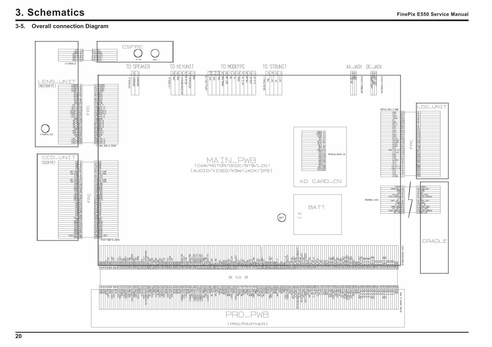
3-5. Overall connection Diagram
21
3. SchematicsFinePix E550 Service Manual
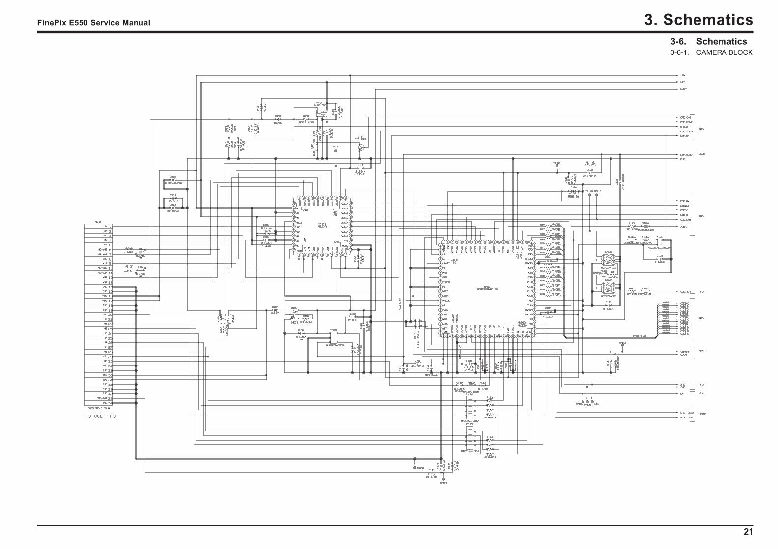
3-6. Schematics3-6-1. CAMERA BLOCK
22
3. Schematics FinePix E550 Service Manual
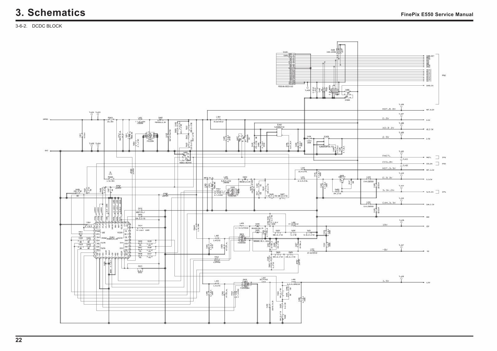
3-6-2. DCDC BLOCK
23
3. SchematicsFinePix E550 Service Manual
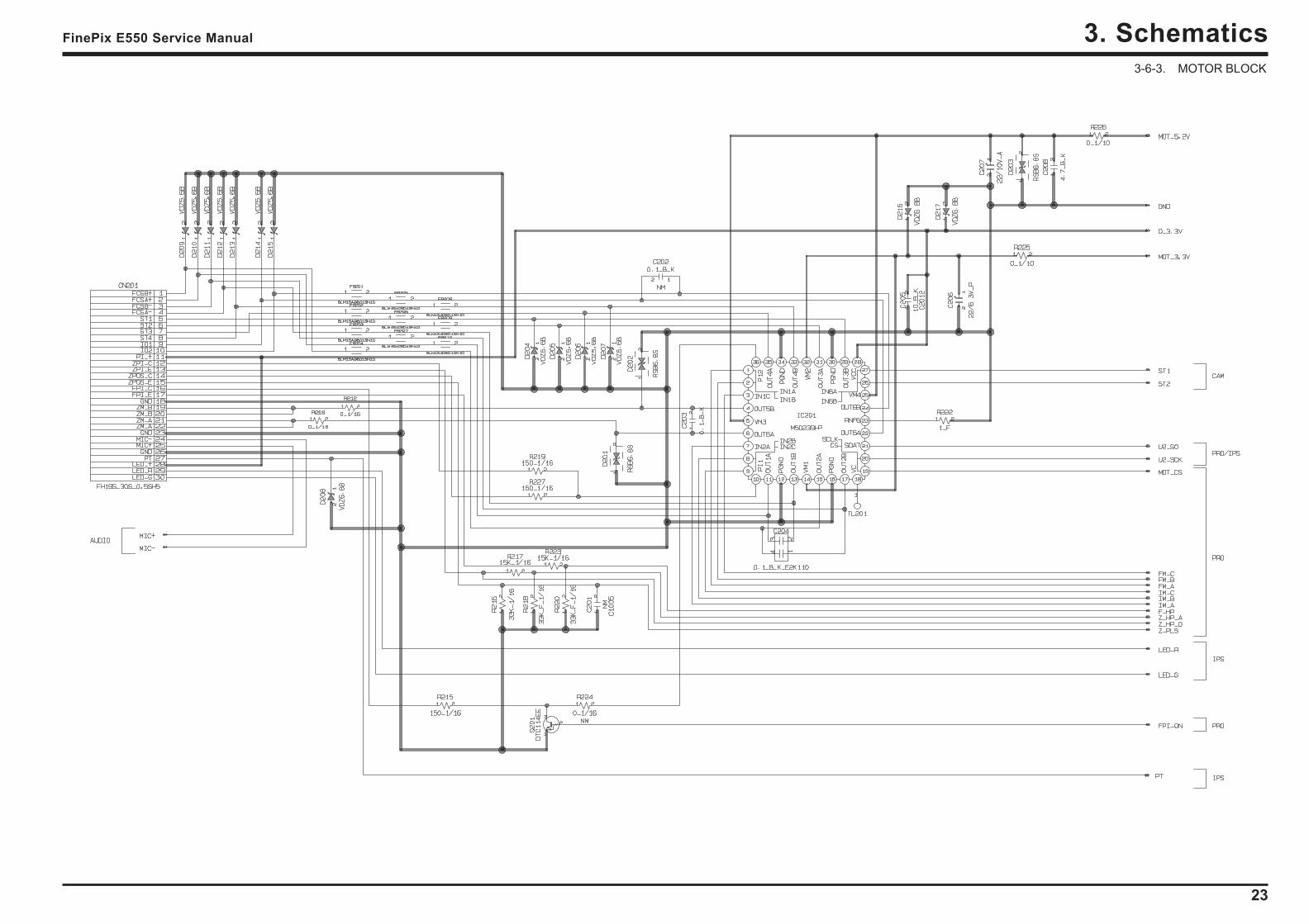
3-6-3. MOTOR BLOCK
24
3. Schematics FinePix E550 Service Manual
3-6-4. PROCESS BLOCK

25
3. SchematicsFinePix E550 Service Manual
3-6-5. AUIDO BLOCK
26
3. Schematics FinePix E550 Service Manual
3-6-6. IPS BLOCK

27
3. SchematicsFinePix E550 Service Manual
3-6-7. JACK BLOCK
28
3. Schematics FinePix E550 Service Manual
3-6-8. KSW BLOCK
29
3. SchematicsFinePix E550 Service Manual
3-6-9. LCD BLOCK
30
3. Schematics FinePix E550 Service Manual
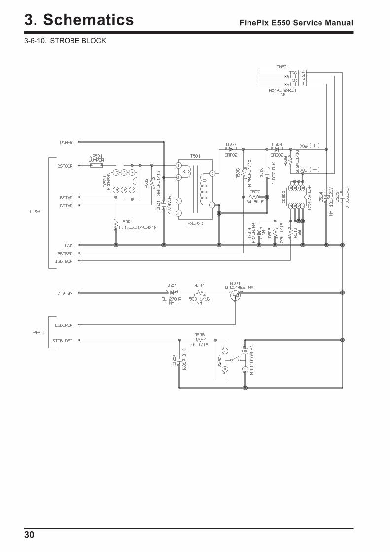
3-6-10. STROBE BLOCK
31
3. SchematicsFinePix E550 Service Manual
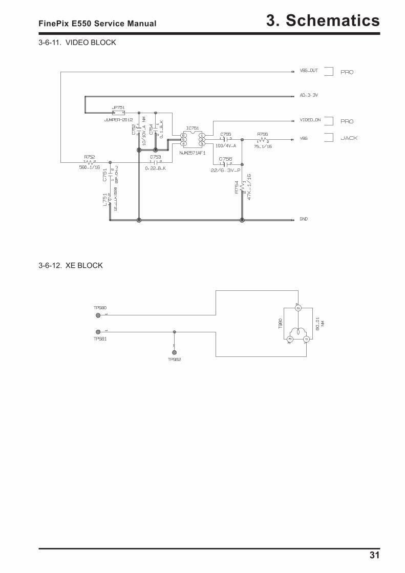
3-6-11. VIDEO BLOCK
3-6-12. XE BLOCK
32
3. Schematics FinePix E550 Service Manual
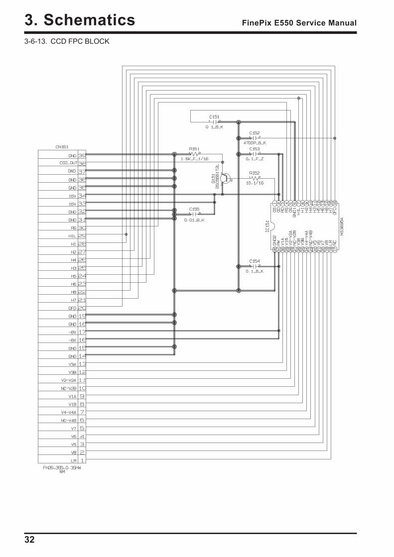
3-6-13. CCD FPC BLOCK
33
3. SchematicsFinePix E550 Service Manual
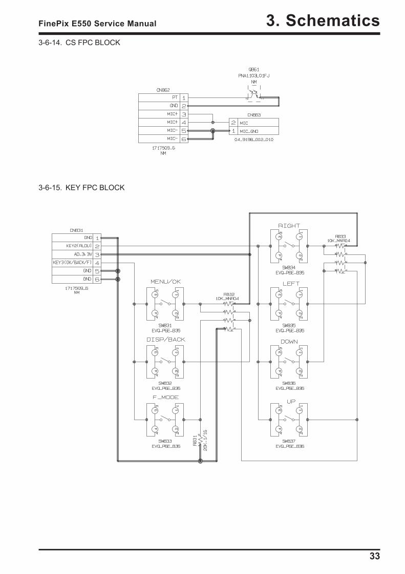
3-6-14. CS FPC BLOCK
3-6-15. KEY FPC BLOCK
34
3. Schematics FinePix E550 Service Manual
3-6-16. MODE FPC BLOCK
35
3. SchematicsFinePix E550 Service Manual
3-6-17. PARTNER BLOCK
36
3. Schematics FinePix E550 Service Manual
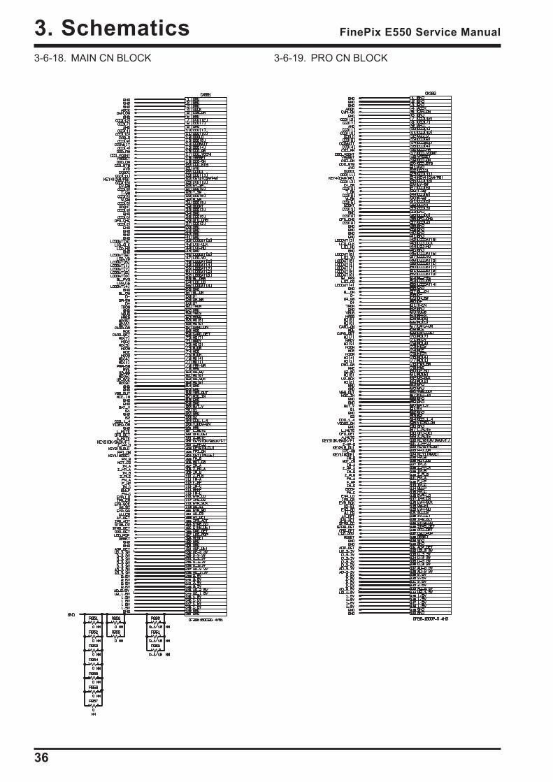
3-6-18. MAIN CN BLOCK 3-6-19. PRO CN BLOCK
37
3. SchematicsFinePix E550 Service Manual
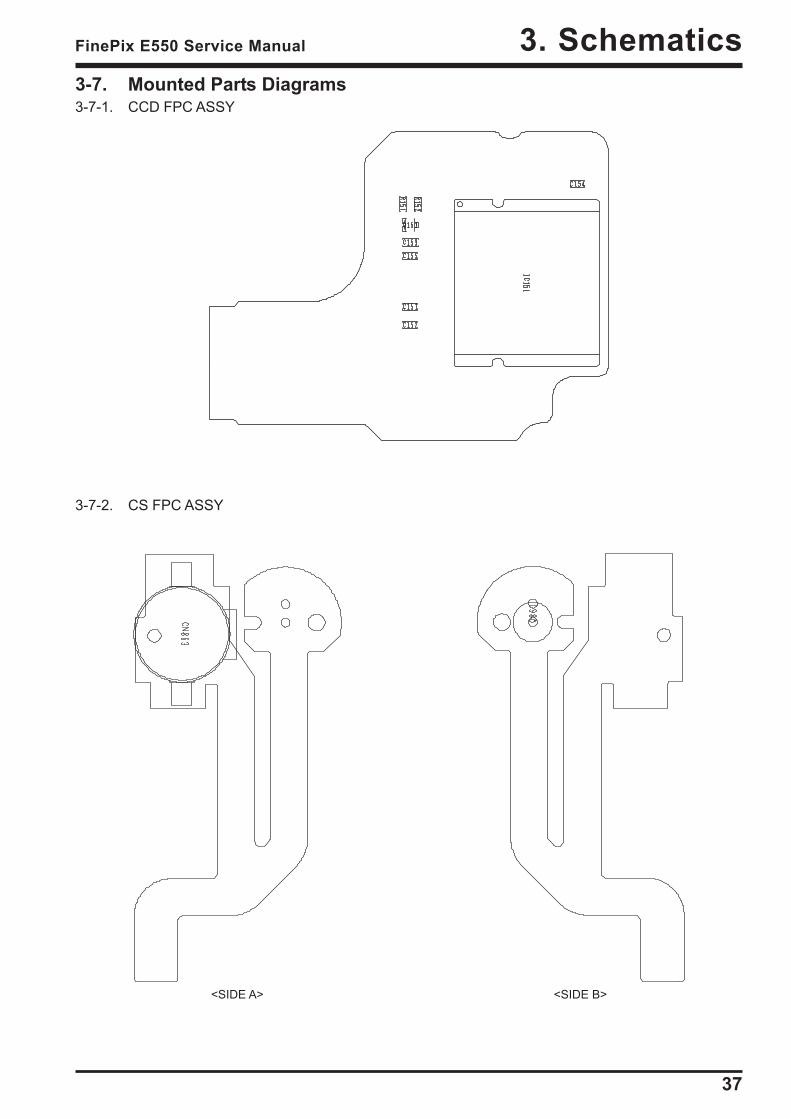
3-7. Mounted Parts Diagrams3-7-1. CCD FPC ASSY
<SIDE A> <SIDE B>
3-7-2. CS FPC ASSY
38
3. Schematics FinePix E550 Service Manual
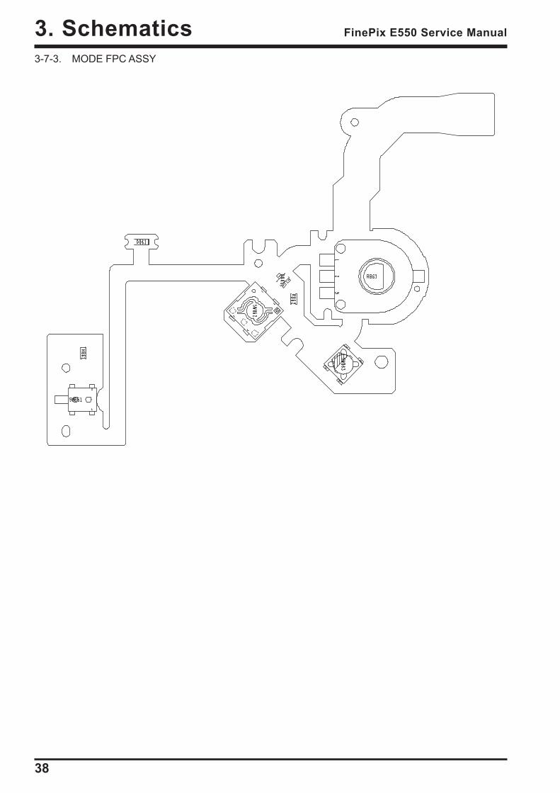
3-7-3. MODE FPC ASSY
39
3. SchematicsFinePix E550 Service Manual
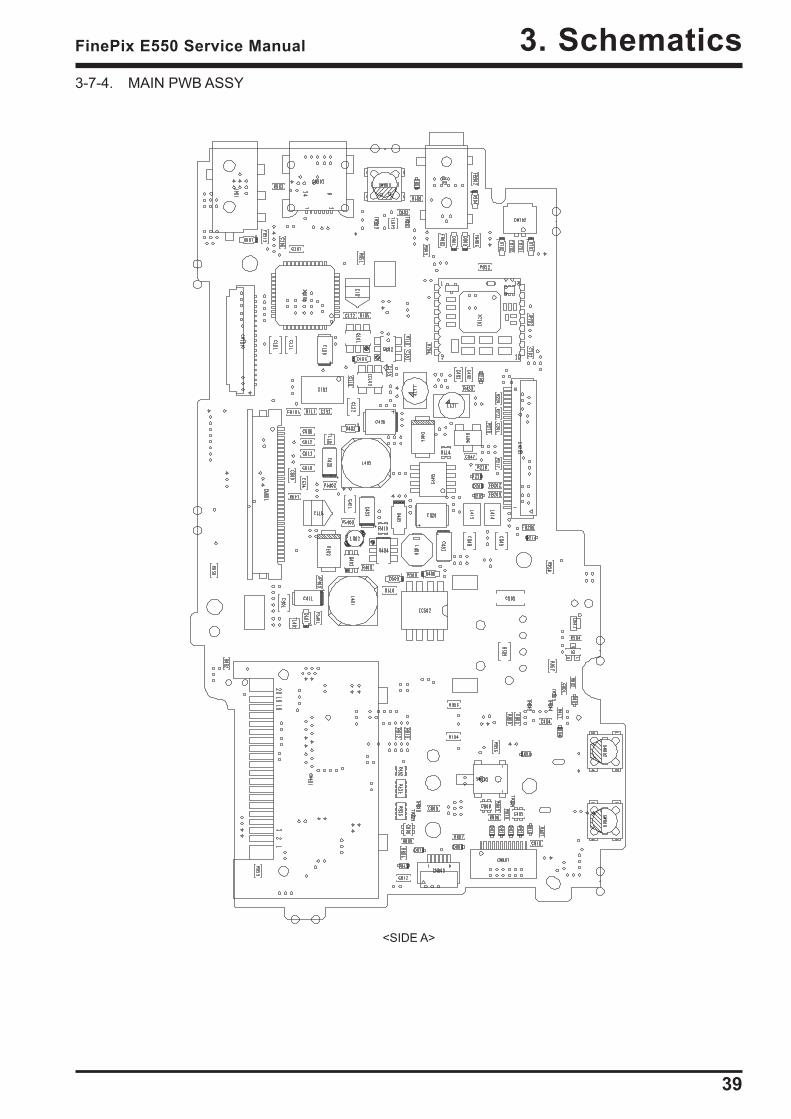
<SIDE A>
3-7-4. MAIN PWB ASSY
40
3. Schematics FinePix E550 Service Manual
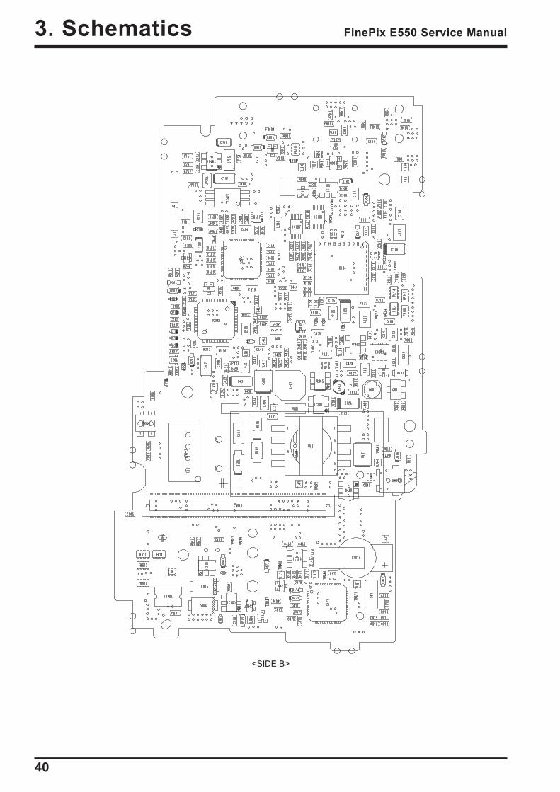
<SIDE B>
41
3. SchematicsFinePix E550 Service Manual
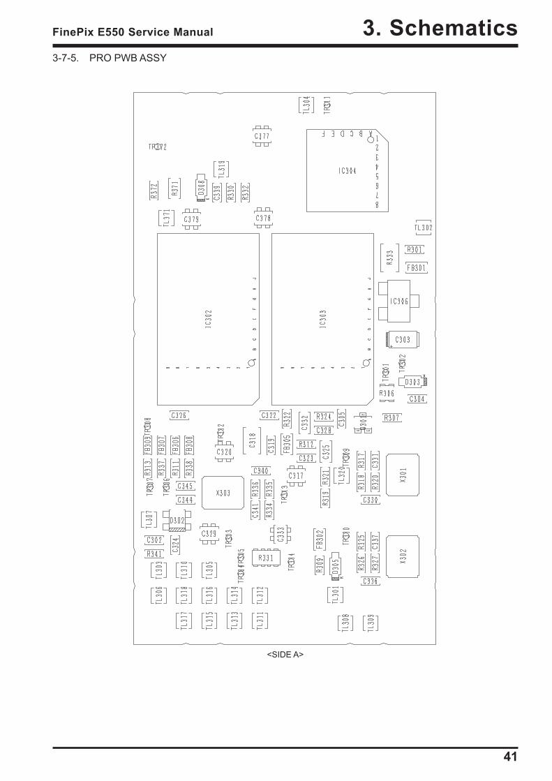
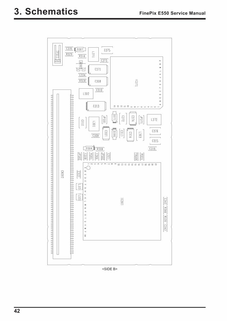
3-7-5. PRO PWB ASSY
<SIDE A>
42
3. Schematics FinePix E550 Service Manual
<SIDE B>
43
4. AdjustmentsFinePix E550 Service Manual
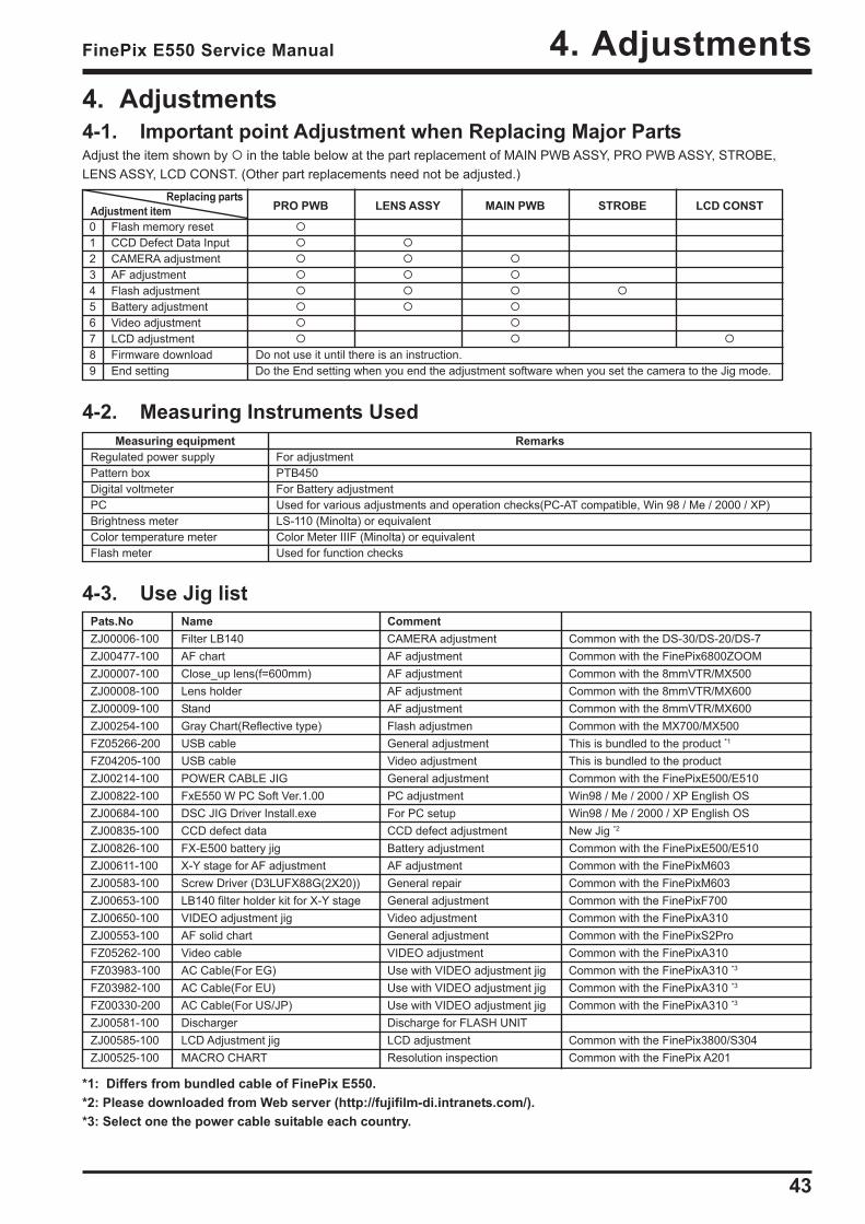
4. Adjustments4-1. Important point Adjustment when Replacing Major PartsAdjust the item shown by in the table below at the part replacement of MAIN PWB ASSY, PRO PWB ASSY, STROBE,LENS ASSY, LCD CONST. (Other part replacements need not be adjusted.)
Pats.No Name CommentZJ00006-100 Filter LB140 CAMERA adjustment Common with the DS-30/DS-20/DS-7ZJ00477-100 AF chart AF adjustment Common with the FinePix6800ZOOMZJ00007-100 Close_up lens(f=600mm) AF adjustment Common with the 8mmVTR/MX500ZJ00008-100 Lens holder AF adjustment Common with the 8mmVTR/MX600ZJ00009-100 Stand AF adjustment Common with the 8mmVTR/MX600ZJ00254-100 Gray Chart(Reflective type) Flash adjustmen Common with the MX700/MX500FZ05266-200 USB cable General adjustment This is bundled to the product *1
FZ04205-100 USB cable Video adjustment This is bundled to the productZJ00214-100 POWER CABLE JIG General adjustment Common with the FinePixE500/E510ZJ00822-100 FxE550 W PC Soft Ver.1.00 PC adjustment Win98 / Me / 2000 / XP English OSZJ00684-100 DSC JIG Driver Install.exe For PC setup Win98 / Me / 2000 / XP English OSZJ00835-100 CCD defect data CCD defect adjustment New Jig *2
ZJ00826-100 FX-E500 battery jig Battery adjustment Common with the FinePixE500/E510ZJ00611-100 X-Y stage for AF adjustment AF adjustment Common with the FinePixM603ZJ00583-100 Screw Driver (D3LUFX88G(2X20)) General repair Common with the FinePixM603ZJ00653-100 LB140 filter holder kit for X-Y stage General adjustment Common with the FinePixF700ZJ00650-100 VIDEO adjustment jig Video adjustment Common with the FinePixA310ZJ00553-100 AF solid chart General adjustment Common with the FinePixS2ProFZ05262-100 Video cable VIDEO adjustment Common with the FinePixA310FZ03983-100 AC Cable(For EG) Use with VIDEO adjustment jig Common with the FinePixA310 *3
FZ03982-100 AC Cable(For EU) Use with VIDEO adjustment jig Common with the FinePixA310 *3
FZ00330-200 AC Cable(For US/JP) Use with VIDEO adjustment jig Common with the FinePixA310 *3
ZJ00581-100 Discharger Discharge for FLASH UNITZJ00585-100 LCD Adjustment jig LCD adjustment Common with the FinePix3800/S304ZJ00525-100 MACRO CHART Resolution inspection Common with the FinePix A201
Replacing partsAdjustment item PRO PWB LENS ASSY MAIN PWB STROBE LCD CONST
0 Flash memory reset1 CCD Defect Data Input2 CAMERA adjustment3 AF adjustment4 Flash adjustment5 Battery adjustment6 Video adjustment7 LCD adjustment8 Firmware download Do not use it until there is an instruction.9 End setting Do the End setting when you end the adjustment software when you set the camera to the Jig mode.
Measuring equipment RemarksRegulated power supply For adjustmentPattern box PTB450Digital voltmeter For Battery adjustmentPC Used for various adjustments and operation checks(PC-AT compatible, Win 98 / Me / 2000 / XP)Brightness meter LS-110 (Minolta) or equivalentColor temperature meter Color Meter IIIF (Minolta) or equivalentFlash meter Used for function checks
4-2. Measuring Instruments Used
4-3. Use Jig list
*1: Differs from bundled cable of FinePix E550.*2: Please downloaded from Web server (http://fujifilm-di.intranets.com/).*3: Select one the power cable suitable each country.
44
4. Adjustments FinePix E550 Service Manual
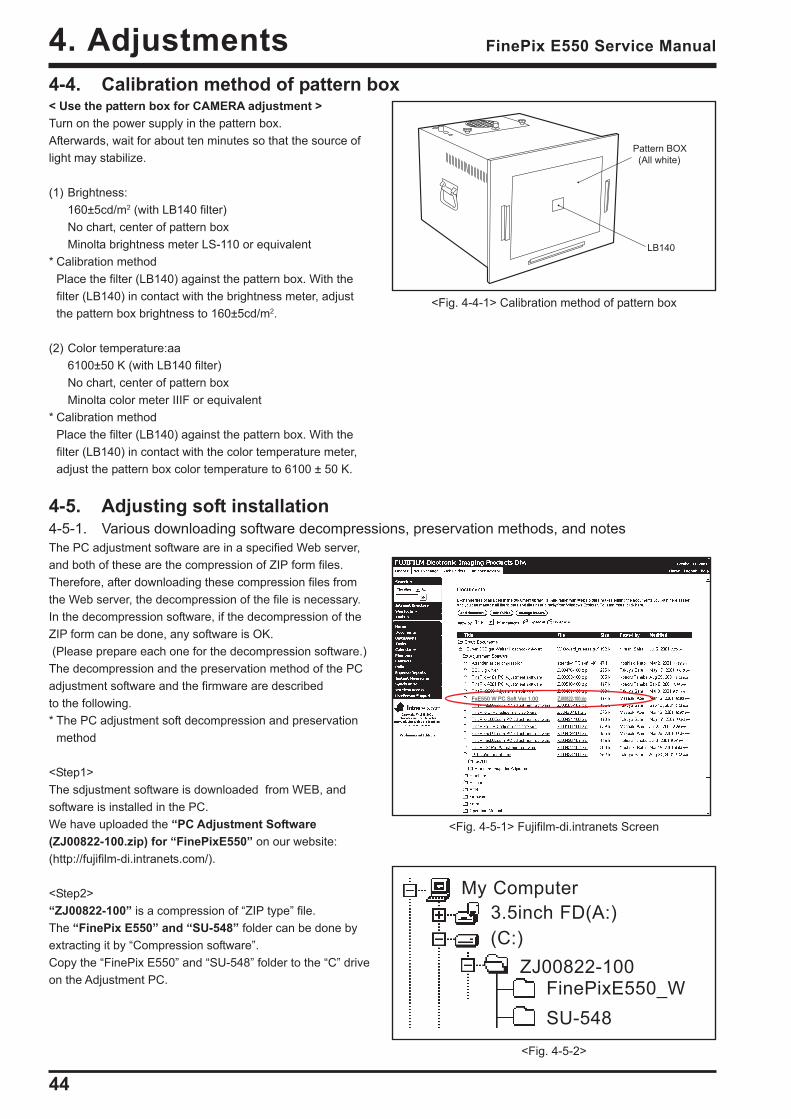
4-4. Calibration method of pattern box< Use the pattern box for CAMERA adjustment >Turn on the power supply in the pattern box.Afterwards, wait for about ten minutes so that the source oflight may stabilize.
(1) Brightness:160±5cd/m2 (with LB140 filter)No chart, center of pattern boxMinolta brightness meter LS-110 or equivalent
* Calibration methodPlace the filter (LB140) against the pattern box. With thefilter (LB140) in contact with the brightness meter, adjustthe pattern box brightness to 160±5cd/m2.
(2) Color temperature:aa6100±50 K (with LB140 filter)No chart, center of pattern boxMinolta color meter IIIF or equivalent
* Calibration methodPlace the filter (LB140) against the pattern box. With thefilter (LB140) in contact with the color temperature meter,adjust the pattern box color temperature to 6100 ± 50 K.
4-5. Adjusting soft installation4-5-1. Various downloading software decompressions, preservation methods, and notesThe PC adjustment software are in a specified Web server,and both of these are the compression of ZIP form files.Therefore, after downloading these compression files fromthe Web server, the decompression of the file is necessary.In the decompression software, if the decompression of theZIP form can be done, any software is OK. (Please prepare each one for the decompression software.)The decompression and the preservation method of the PCadjustment software and the firmware are describedto the following.* The PC adjustment soft decompression and preservation
method
<Step1>The sdjustment software is downloaded from WEB, andsoftware is installed in the PC.We have uploaded the “PC Adjustment Software(ZJ00822-100.zip) for “FinePixE550” on our website:(http://fujifilm-di.intranets.com/).
<Step2>“ZJ00822-100” is a compression of “ZIP type” file.The “FinePix E550” and “SU-548” folder can be done byextracting it by “Compression software”.Copy the “FinePix E550” and “SU-548” folder to the “C” driveon the Adjustment PC.
<Fig. 4-4-1> Calibration method of pattern box
LB140
Pattern BOX
(All white)
ZJ00822-100
My Computer3.5inch FD(A:)(C:)
FinePixE550_W
<Fig. 4-5-2>
<Fig. 4-5-1> Fujifilm-di.intranets Screen
FxE550 W PC Soft Ver.1.00 ZJ00822-100.zip
SU-548
45
4. AdjustmentsFinePix E550 Service Manual
ZJ00822-100
My Computer3.5inch FD(A:)(C:)
FinePixE550_W
<Fig. 4-5-3>
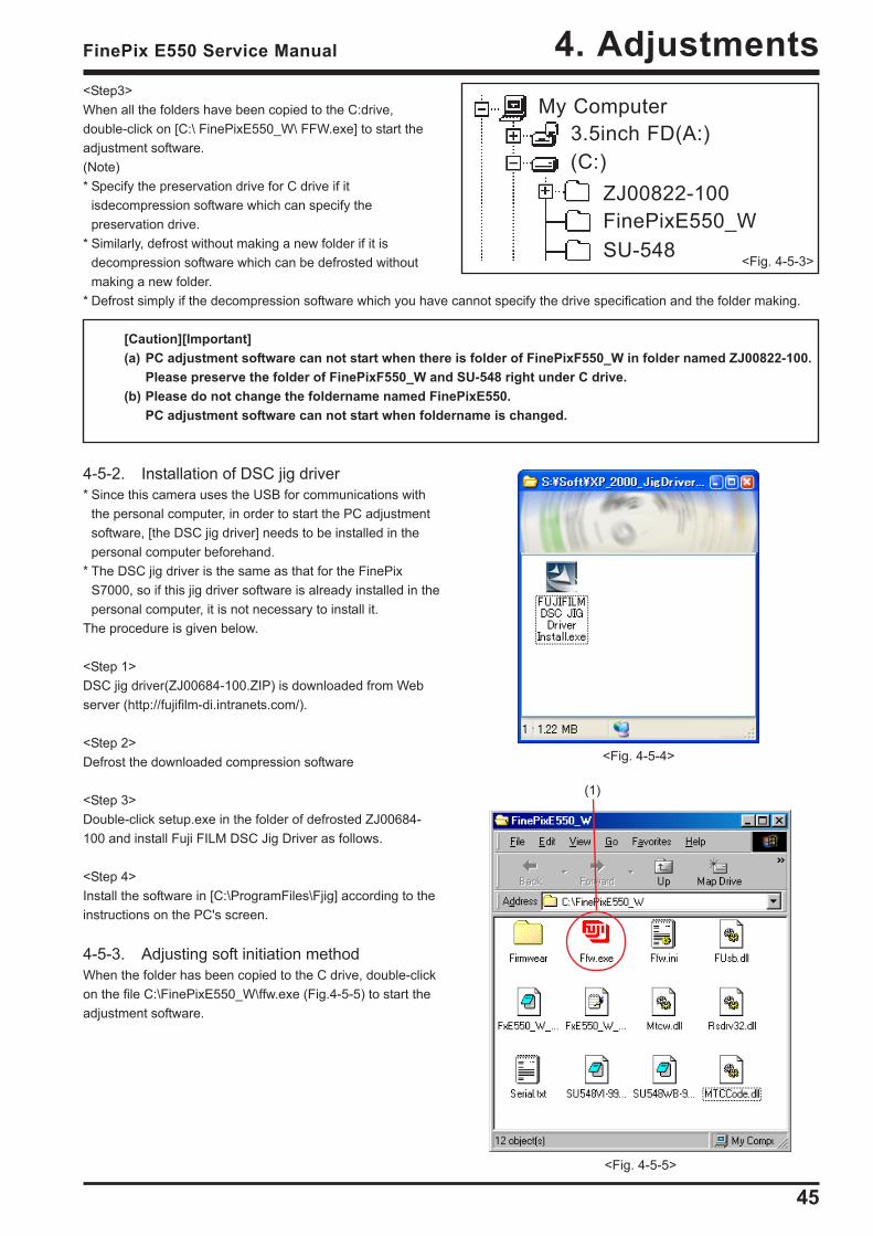
<Step3>When all the folders have been copied to the C:drive,double-click on [C:\ FinePixE550_W\ FFW.exe] to start theadjustment software.(Note)* Specify the preservation drive for C drive if it
isdecompression software which can specify thepreservation drive.
* Similarly, defrost without making a new folder if it isdecompression software which can be defrosted withoutmaking a new folder.
* Defrost simply if the decompression software which you have cannot specify the drive specification and the folder making.
[Caution][Important](a) PC adjustment software can not start when there is folder of FinePixF550_W in folder named ZJ00822-100.
Please preserve the folder of FinePixF550_W and SU-548 right under C drive.(b) Please do not change the foldername named FinePixE550.
PC adjustment software can not start when foldername is changed.
4-5-2. Installation of DSC jig driver* Since this camera uses the USB for communications with
the personal computer, in order to start the PC adjustmentsoftware, [the DSC jig driver] needs to be installed in thepersonal computer beforehand.
* The DSC jig driver is the same as that for the FinePixS7000, so if this jig driver software is already installed in thepersonal computer, it is not necessary to install it.
The procedure is given below.
<Step 1>DSC jig driver(ZJ00684-100.ZIP) is downloaded from Webserver (http://fujifilm-di.intranets.com/).
<Step 2>Defrost the downloaded compression software
<Step 3>Double-click setup.exe in the folder of defrosted ZJ00684-100 and install Fuji FILM DSC Jig Driver as follows.
<Step 4>Install the software in [C:\ProgramFiles\Fjig] according to theinstructions on the PC's screen.
4-5-3. Adjusting soft initiation methodWhen the folder has been copied to the C drive, double-clickon the file C:\FinePixE550_W\ffw.exe (Fig.4-5-5) to start theadjustment software.
SU-548
(1)
<Fig. 4-5-4>
<Fig. 4-5-5>
46
4. Adjustments FinePix E550 Service Manual
4-6. Initial Settings of the Adjustment Software* The initial settings are already written in the "FFW.ini" file,
therefore perform the following procedure to the letter.Note that, if you change file names, the software will notstart up.
* The initial settings of steps 3 to 6 are already set in the"FFW.ini" file. Therefore, you need only to check them.
* Do not rewrite the user program (FxE550_W_0.ff). If theprogram is rewritten, the adjustment software will notstartup.
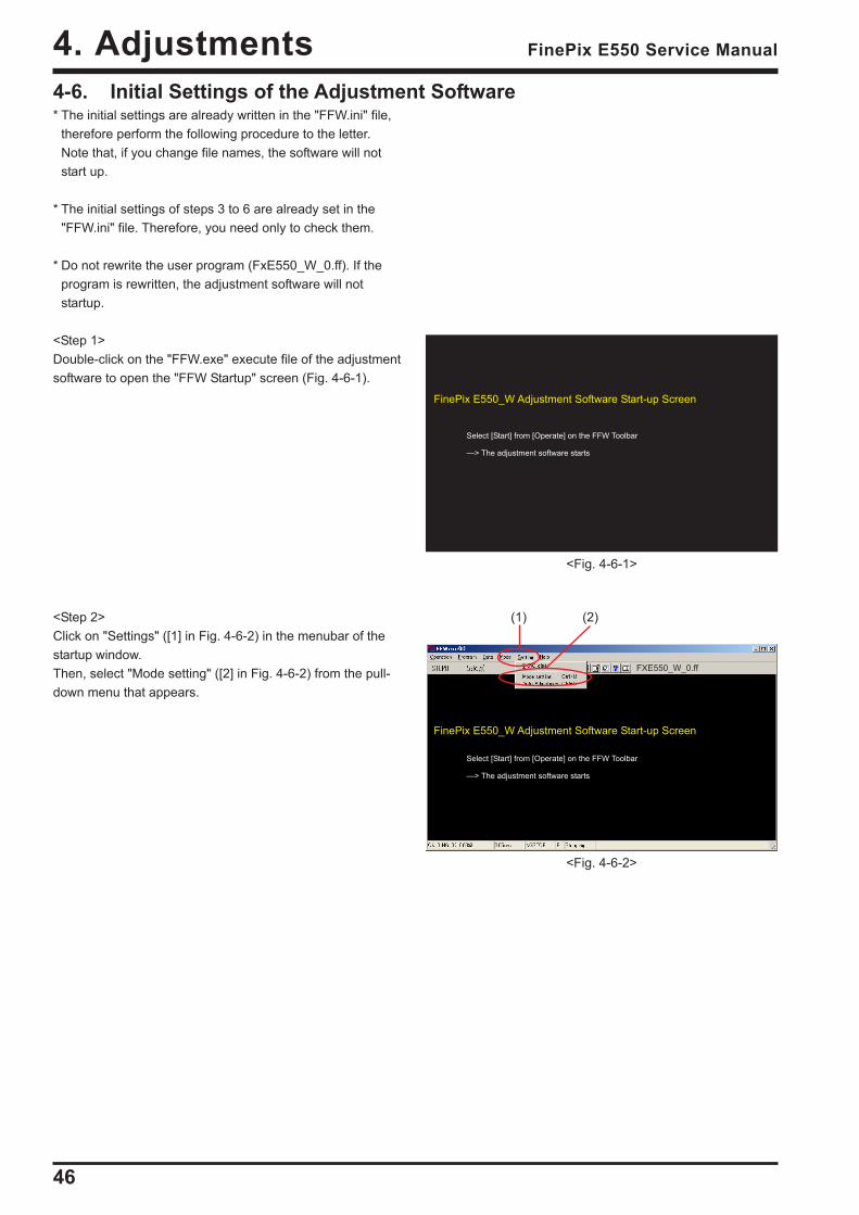
<Step 1>Double-click on the "FFW.exe" execute file of the adjustmentsoftware to open the "FFW Startup" screen (Fig. 4-6-1).
<Step 2>Click on "Settings" ([1] in Fig. 4-6-2) in the menubar of thestartup window.Then, select "Mode setting" ([2] in Fig. 4-6-2) from the pull-down menu that appears.
<Fig. 4-6-2>
(1) (2)
FinePix E550_W Adjustment Software Start-up Screen
Select [Start] from [Operate] on the FFW Toolbar
—> The adjustment software starts
FinePix E550_W Adjustment Software Start-up Screen
Select [Start] from [Operate] on the FFW Toolbar
—> The adjustment software starts
<Fig. 4-6-1>
FXE550_W_0.ff
47
4. AdjustmentsFinePix E550 Service Manual
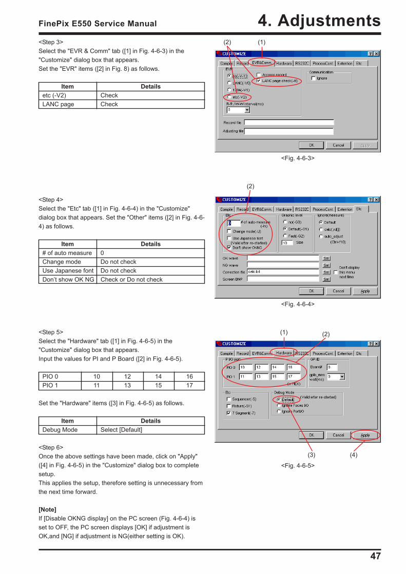
<Step 3>Select the "EVR & Comm" tab ([1] in Fig. 4-6-3) in the"Customize" dialog box that appears.Set the "EVR" items ([2] in Fig. 8) as follows.
Item Detailsetc (-V2) CheckLANC page Check
<Step 4>Select the "Etc" tab ([1] in Fig. 4-6-4) in the "Customize"dialog box that appears. Set the "Other" items ([2] in Fig. 4-6-4) as follows.
Item Details# of auto measure 0Change mode Do not checkUse Japanese font Do not checkDon’t show OK NG Check or Do not check
<Step 5>Select the "Hardware" tab ([1] in Fig. 4-6-5) in the"Customize" dialog box that appears.Input the values for PI and P Board ([2] in Fig. 4-6-5).
PIO 0 10 12 14 16PIO 1 11 13 15 17
Set the "Hardware" items ([3] in Fig. 4-6-5) as follows.
Item DetailsDebug Mode Select [Default]
<Step 6>Once the above settings have been made, click on "Apply"([4] in Fig. 4-6-5) in the "Customize" dialog box to completesetup.This applies the setup, therefore setting is unnecessary fromthe next time forward.
[Note]If [Disable OKNG display] on the PC screen (Fig. 4-6-4) isset to OFF, the PC screen displays [OK] if adjustment isOK,and [NG] if adjustment is NG(either setting is OK).
<Fig. 4-6-3>
(1)(2)
<Fig. 4-6-5>
(2)(1)
(4)(3)
(2)
<Fig. 4-6-4>
48
4. Adjustments FinePix E550 Service Manual
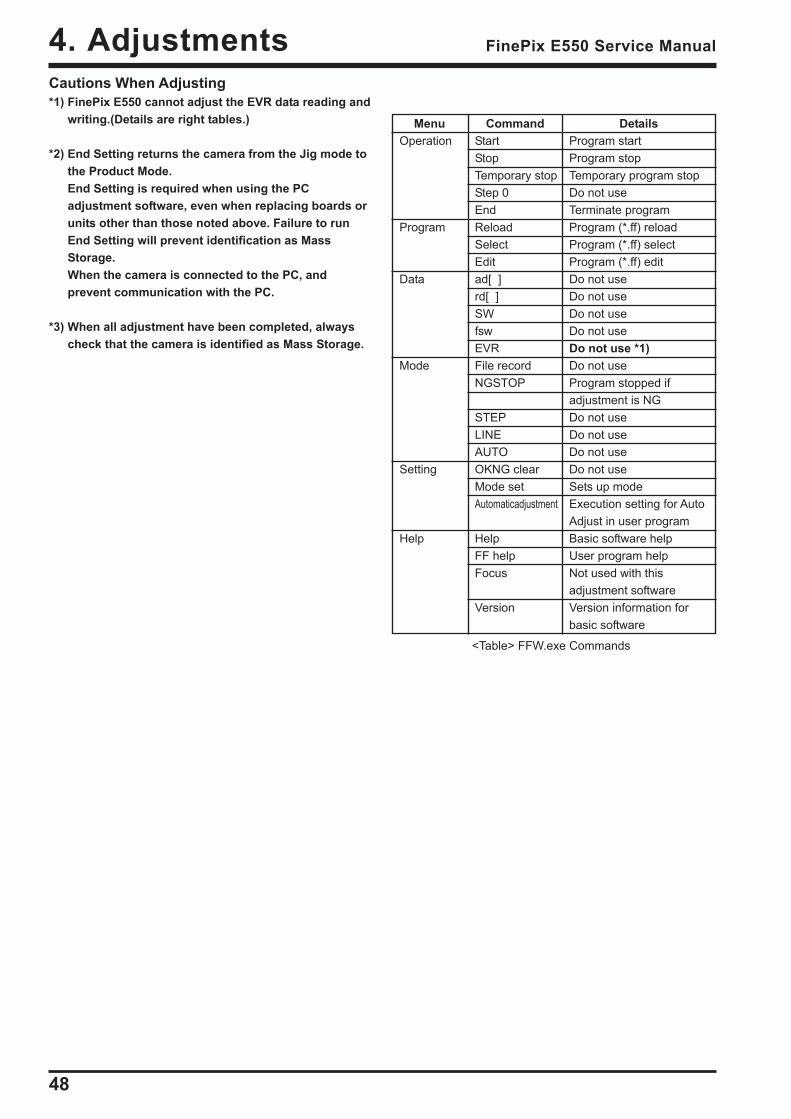
Menu Command DetailsOperation Start Program start
Stop Program stopTemporary stop Temporary program stopStep 0 Do not useEnd Terminate program
Program Reload Program (*.ff) reloadSelect Program (*.ff) selectEdit Program (*.ff) edit
Data ad[ ] Do not userd[ ] Do not useSW Do not usefsw Do not useEVR Do not use *1)
Mode File record Do not useNGSTOP Program stopped if
adjustment is NGSTEP Do not useLINE Do not useAUTO Do not use
Setting OKNG clear Do not useMode set Sets up modeAutomaticadjustment Execution setting for Auto
Adjust in user programHelp Help Basic software help
FF help User program helpFocus Not used with this
adjustment softwareVersion Version information for
basic software
<Table> FFW.exe Commands
Cautions When Adjusting*1) FinePix E550 cannot adjust the EVR data reading and
writing.(Details are right tables.)
*2) End Setting returns the camera from the Jig mode tothe Product Mode.End Setting is required when using the PCadjustment software, even when replacing boards orunits other than those noted above. Failure to runEnd Setting will prevent identification as MassStorage.When the camera is connected to the PC, andprevent communication with the PC.
*3) When all adjustment have been completed, alwayscheck that the camera is identified as Mass Storage.
49
4. AdjustmentsFinePix E550 Service Manual
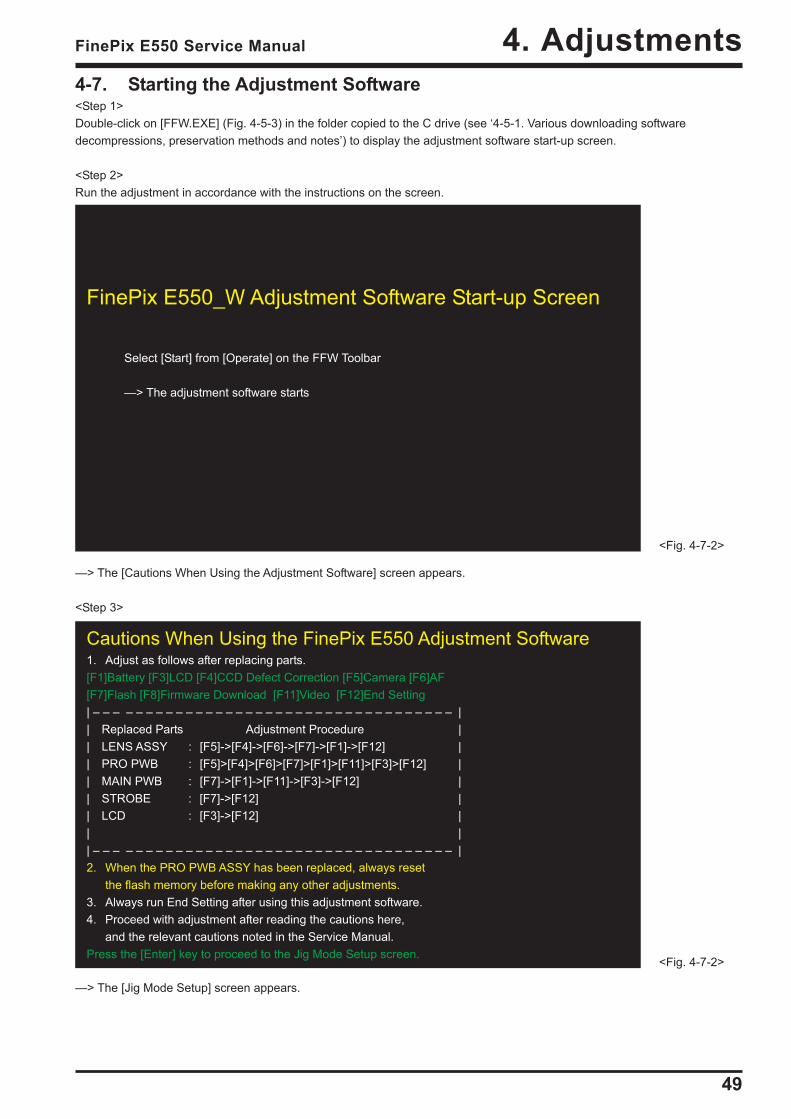
Cautions When Using the FinePix E550 Adjustment Software1. Adjust as follows after replacing parts.[F1]Battery [F3]LCD [F4]CCD Defect Correction [F5]Camera [F6]AF[F7]Flash [F8]Firmware Download [F11]Video [F12]End Setting| – – – – – – – – – – – – – – – – – – – – – – – – – – – – – – – – – – – – || Replaced Parts Adjustment Procedure || LENS ASSY : [F5]->[F4]->[F6]->[F7]->[F1]->[F12] || PRO PWB : [F5]>[F4]>[F6]>[F7]>[F1]>[F11]>[F3]>[F12] || MAIN PWB : [F7]->[F1]->[F11]->[F3]->[F12] || STROBE : [F7]->[F12] || LCD : [F3]->[F12] || || – – – – – – – – – – – – – – – – – – – – – – – – – – – – – – – – – – – – |2. When the PRO PWB ASSY has been replaced, always reset
the flash memory before making any other adjustments.3. Always run End Setting after using this adjustment software.4. Proceed with adjustment after reading the cautions here,
and the relevant cautions noted in the Service Manual.Press the [Enter] key to proceed to the Jig Mode Setup screen.
<Fig. 4-7-2>
FinePix E550_W Adjustment Software Start-up Screen
Select [Start] from [Operate] on the FFW Toolbar
—> The adjustment software starts
<Fig. 4-7-2>
4-7. Starting the Adjustment Software<Step 1>Double-click on [FFW.EXE] (Fig. 4-5-3) in the folder copied to the C drive (see ‘4-5-1. Various downloading softwaredecompressions, preservation methods and notes’) to display the adjustment software start-up screen.
<Step 2>Run the adjustment in accordance with the instructions on the screen.
—> The [Cautions When Using the Adjustment Software] screen appears.
<Step 3>
—> The [Jig Mode Setup] screen appears.
50
4. Adjustments FinePix E550 Service Manual
<Step 4>
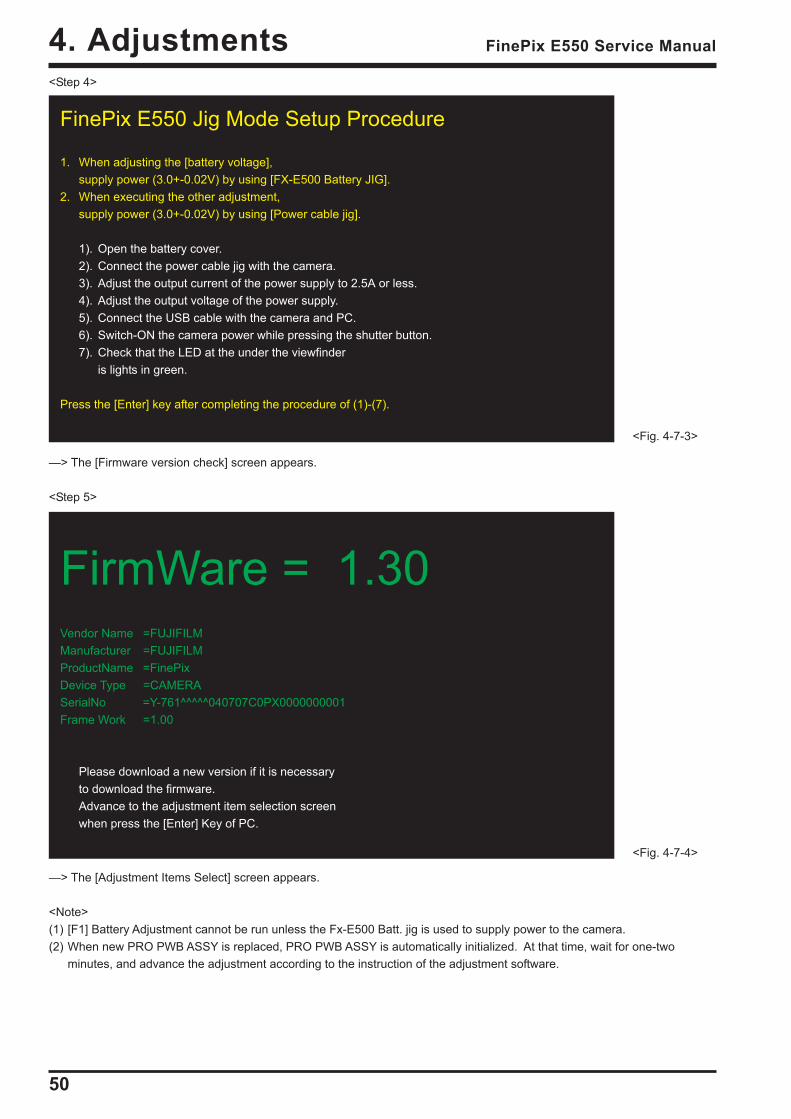
—> The [Firmware version check] screen appears.
<Step 5>
—> The [Adjustment Items Select] screen appears.
<Note>(1) [F1] Battery Adjustment cannot be run unless the Fx-E500 Batt. jig is used to supply power to the camera.(2) When new PRO PWB ASSY is replaced, PRO PWB ASSY is automatically initialized. At that time, wait for one-two
minutes, and advance the adjustment according to the instruction of the adjustment software.
FinePix E550 Jig Mode Setup Procedure
1. When adjusting the [battery voltage],supply power (3.0+-0.02V) by using [FX-E500 Battery JIG].
2. When executing the other adjustment,supply power (3.0+-0.02V) by using [Power cable jig].
1). Open the battery cover.2). Connect the power cable jig with the camera.3). Adjust the output current of the power supply to 2.5A or less.4). Adjust the output voltage of the power supply.5). Connect the USB cable with the camera and PC.6). Switch-ON the camera power while pressing the shutter button.7). Check that the LED at the under the viewfinder
is lights in green.
Press the [Enter] key after completing the procedure of (1)-(7).
<Fig. 4-7-3>
FirmWare = 1.30Vendor Name =FUJIFILMManufacturer =FUJIFILMProductName =FinePixDevice Type =CAMERASerialNo =Y-761^^^^^040707C0PX0000000001Frame Work =1.00
Please download a new version if it is necessaryto download the firmware.Advance to the adjustment item selection screenwhen press the [Enter] Key of PC.
<Fig. 4-7-4>
51
4. AdjustmentsFinePix E550 Service Manual
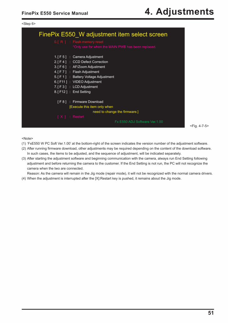
FinePix E550_W adjustment item select screen0.[ R ] : Flash memory reset
*Only use for when the MAIN PWB has been replaced.
1. [ F 5 ] : Camera Adjustment2. [ F 4 ] : CCD Defect Correction3. [ F 6 ] : AF/Zoom Adjustment4. [ F 7 ] : Flash Adjustment5. [ F 1 ] : Battery Voltage Adjustment6. [ F11 ] : VIDEO Adjustment7. [ F 3 ] : LCD Adjustment8. [ F12 ] : End Setting
[ F 8 ] : Firmware Download[Execute this item only when
need to change the firmware.][ X ] : Restart
Fx E550 ADJ Software Ver.1.00<Fig. 4-7-5>
<Step 6>
<Note>(1) ‘FxE550 W PC Soft Ver.1.00’ at the bottom-right of the screen indicates the version number of the adjustment software.(2) After running firmware download, other adjustments may be required depending on the content of the download software.
In such cases, the items to be adjusted, and the sequence of adjustment, will be indicated separately.(3) After starting the adjustment software and beginning communication with the camera, always run End Setting following
adjustment and before returning the camera to the customer. If the End Setting is not run, the PC will not recognize thecamera when the two are connected.Reason: As the camera will remain in the Jig mode (repair mode), it will not be recognized with the normal camera drivers.
(4) When the adjustment is interrupted after the [X]:Restart key is pushed, it remains about the Jig mode.

52
4. Adjustments FinePix E550 Service Manual
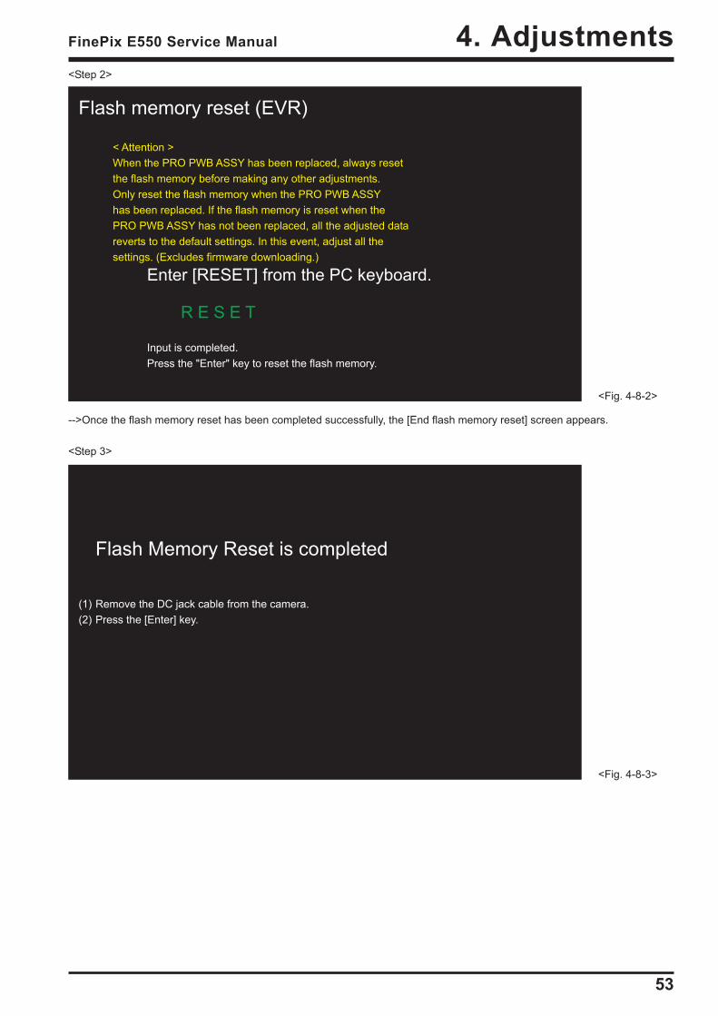
4-8. [R] : Flash Memory Reset<Note>Only reset the flash memory when the PRO PWB ASSY has been replaced.When the PRO PWB ASSY has been replaced, always reset the flash memory before making any other adjustments.If the flash memory is reset when the PRO PWB ASSY has not been replaced, all the adjusted data reverts to the defaultsettings.In this event, adjust all the settings.(Excludes firmware downloading.)After the PRO PWB ASSY has been replaced, proceeding with other adjustments without first resetting the flash memorywill prevent the successful completion of the adjustments.(In some cases the camera may be completely disabled.)If this occurs, set the camera to jig mode again and then reset the flash memory.
<Step 1>In the adjustment item selection screen, select [R]: Reset flash memory.-->The flash memory reset confirmation screen appears.
-->The [Reconfirm flash memory reset] screen then appears.
Flash memory reset (EVR)
< Attention >When the PRO PWB ASSY has been replaced, always resetthe flash memory before making any other adjustments.Only reset the flash memory when the PRO PWB ASSYhas been replaced. If the flash memory is reset when thePRO PWB ASSY has not been replaced, all the adjusted datareverts to the default settings. In this event, adjust all thesettings. (Excludes firmware downloading.)
Enter [RESET] from the PC keyboard.
<Fig. 4-8-1>
53
4. AdjustmentsFinePix E550 Service Manual
Flash memory reset (EVR)
< Attention >When the PRO PWB ASSY has been replaced, always resetthe flash memory before making any other adjustments.Only reset the flash memory when the PRO PWB ASSYhas been replaced. If the flash memory is reset when thePRO PWB ASSY has not been replaced, all the adjusted datareverts to the default settings. In this event, adjust all thesettings. (Excludes firmware downloading.)
Enter [RESET] from the PC keyboard.
R E S E T
Input is completed.Press the "Enter" key to reset the flash memory.
<Fig. 4-8-2>
Flash Memory Reset is completed
(1) Remove the DC jack cable from the camera.(2) Press the [Enter] key.
<Fig. 4-8-3>
<Step 2>
-->Once the flash memory reset has been completed successfully, the [End flash memory reset] screen appears.
<Step 3>
54
4. Adjustments FinePix E550 Service Manual
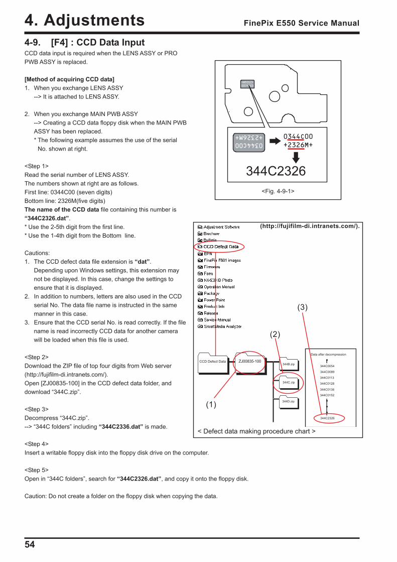
4-9. [F4] : CCD Data InputCCD data input is required when the LENS ASSY or PROPWB ASSY is replaced.
[Method of acquiring CCD data]1. When you exchange LENS ASSY
--> It is attached to LENS ASSY.
2. When you exchange MAIN PWB ASSY--> Creating a CCD data floppy disk when the MAIN PWBASSY has been replaced.* The following example assumes the use of the serial
No. shown at right.
<Step 1>Read the serial number of LENS ASSY.The numbers shown at right are as follows.First line: 0344C00 (seven digits)Bottom line: 2326M(five digits)The name of the CCD data file containing this number is“344C2326.dat”.* Use the 2-5th digit from the first line.* Use the 1-4th digit from the Bottom line.
Cautions:1. The CCD defect data file extension is “dat”.
Depending upon Windows settings, this extension maynot be displayed. In this case, change the settings toensure that it is displayed.
2. In addition to numbers, letters are also used in the CCDserial No. The data file name is instructed in the samemanner in this case.
3. Ensure that the CCD serial No. is read correctly. If the filename is read incorrectly CCD data for another camerawill be loaded when this file is used.
<Step 2>Download the ZIP file of top four digits from Web server(http://fujifilm-di.intranets.com/).Open [ZJ00835-100] in the CCD defect data folder, anddownload “344C.zip”.
<Step 3>Decompress “344C.zip”.--> “344C folders” including “344C2336.dat” is made.
<Step 4>Insert a writable floppy disk into the floppy disk drive on the computer.
<Step 5>Open in “344C folders”, search for “344C2326.dat”, and copy it onto the floppy disk.
Caution: Do not create a folder on the floppy disk when copying the data.
<Fig. 4-9-1>
(http://fujifilm-di.intranets.com/).
CCD Defect Data ZJ00785-100344B.zip
344C.zip
344D.zip
Data after decompression
344C0089
344C0128
344C0113
344C0136
344C0152
344C0054
344C2326
(3)
(2)
(1)
344C2326
ZJ00835-100
< Defect data making procedure chart >

55
4. AdjustmentsFinePix E550 Service Manual
< Adjustment ><Step 1>Select [F4] CCD Defect Data Input on the [Adjustment Items Select] screen.--> The [CCD Defect Data Input Start] screen appears.
<Step 2>Run the adjustment in accordance with the instructions on the screen.
--> Write the adjustment data to the flash ROM when adjustment has been completed correctly.--> The [CCD Defect Data Input Complete] screen appears.
<Step 3>
CCD Defect data input is completed.Press the [Enter] key to returnto the Adjustment Item Selection Screen.
<Fig. 4-9-3>
CCD Defect data input< Preparations >
(1) Enter the 8-digit ccdserial number in theCCD Data Input dialog box.The file extrension need not be entered.
(2) Insert the floppy diskin the A: drive (floppy disk drive) on the PC.
When preparations (1) - (3) are complete, press the [Enter] key on the PC.( Or, click on the OK button.)
344C2326
<Fig. 4-9-2>
56
4. Adjustments FinePix E550 Service Manual
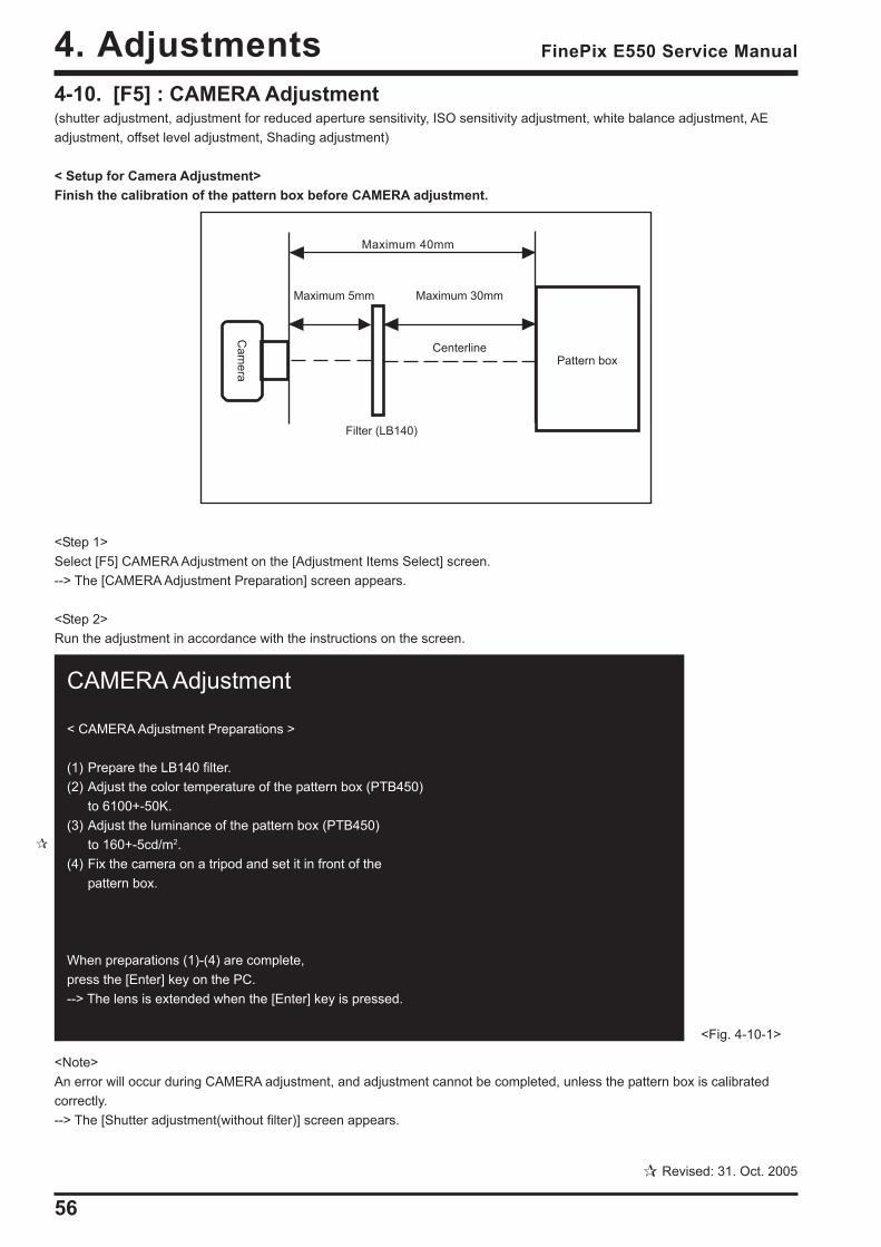
4-10. [F5] : CAMERA Adjustment(shutter adjustment, adjustment for reduced aperture sensitivity, ISO sensitivity adjustment, white balance adjustment, AEadjustment, offset level adjustment, Shading adjustment)
< Setup for Camera Adjustment>Finish the calibration of the pattern box before CAMERA adjustment.
<Step 1>Select [F5] CAMERA Adjustment on the [Adjustment Items Select] screen.--> The [CAMERA Adjustment Preparation] screen appears.
<Step 2>Run the adjustment in accordance with the instructions on the screen.
<Note>An error will occur during CAMERA adjustment, and adjustment cannot be completed, unless the pattern box is calibratedcorrectly.--> The [Shutter adjustment(without filter)] screen appears.
Cam
era
Filter (LB140)
Pattern box
Maximum 5mm
Centerline
Maximum 30mm
Maximum 40mm
CAMERA Adjustment
< CAMERA Adjustment Preparations >
(1) Prepare the LB140 filter.(2) Adjust the color temperature of the pattern box (PTB450)
to 6100+-50K.(3) Adjust the luminance of the pattern box (PTB450)
to 160+-5cd/m2.(4) Fix the camera on a tripod and set it in front of the
pattern box.
When preparations (1)-(4) are complete,press the [Enter] key on the PC.--> The lens is extended when the [Enter] key is pressed.
<Fig. 4-10-1>
Revised: 31. Oct. 2005

57
4. AdjustmentsFinePix E550 Service Manual
Shutter adjustment(1) Set the distance between the camera and pattern box.(2) The LB140 filter is not placed in front of the lens.
When preparations are complete, press the [Enter] key.LB140 filter
------------------------------| | || 5mm or | 30mm or less. || less. | |<--Center--> | <------ Center ------> Pattern box |
(PTB450) |CAMERA |
| | ------------------------------
< Setup for CAMERA Adjustment ><Fig. 4-10-2>
Squeezing sensitivity decrease rate adjustment(1) Set the distance between the camera and pattern box.(2) Place the LB140 filter in front of the lens.
When preparations are complete, press the [Enter] key.LB140 filter
| ------------------------------| | | || 5mm or | 30mm or less. || less. | |<--Center--> | <------ Center ------> Pattern box |
(PTB450) |CAMERA |
| | ------------------------------
< Setup for CAMERA Adjustment ><Fig. 4-10-3>
<Step 3>
--> The [Squeezing sensitivity decrease rate adjustment (with filter)] screen appears.
<Step 4>
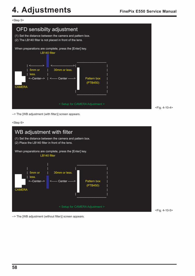
--> The [OFD sensibilty adjustment (without filter)] screen appears.
58
4. Adjustments FinePix E550 Service Manual
WB adjustment with filter(1) Set the distance between the camera and pattern box.(2) Place the LB140 filter in front of the lens.
When preparations are complete, press the [Enter] key.LB140 filter
| ------------------------------| | | || 5mm or | 30mm or less. || less. | |<--Center--> | <------ Center ------> Pattern box |
(PTB450) |CAMERA |
| | ------------------------------
< Setup for CAMERA Adjustment ><Fig. 4-10-5>
OFD sensibilty adjustment(1) Set the distance between the camera and pattern box.(2) The LB140 filter is not placed in front of the lens.
When preparations are complete, press the [Enter] key.LB140 filter
------------------------------| <------------> <---------------------> | || 5mm or | 30mm or less. || less. | |<--Center--> | <------ Center ------> Pattern box |
(PTB450) |CAMERA |
| | ------------------------------
< Setup for CAMERA Adjustment ><Fig. 4-10-4>
<Step 5>
--> The [WB adjustment (with filter)] screen appears.
<Step 6>
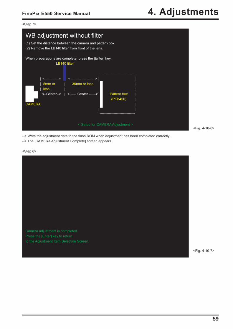
--> The [WB adjustment (without filter)] screen appears.
59
4. AdjustmentsFinePix E550 Service Manual
Camera adjustment is completed.Press the [Enter] key to returnto the Adjustment Item Selection Screen.
<Fig. 4-10-7>
WB adjustment without filter(1) Set the distance between the camera and pattern box.(2) Remove the LB140 filter from front of the lens.
When preparations are complete, press the [Enter] key.LB140 filter
------------------------------| <------------> <---------------------> | || 5mm or | 30mm or less. || less. | |<--Center--> | <------ Center ------> Pattern box |
(PTB450) |CAMERA |
| | ------------------------------
< Setup for CAMERA Adjustment ><Fig. 4-10-6>
<Step 7>
--> Write the adjustment data to the flash ROM when adjustment has been completed correctly.--> The [CAMERA Adjustment Complete] screen appears.
<Step 8>
60
4. Adjustments FinePix E550 Service Manual
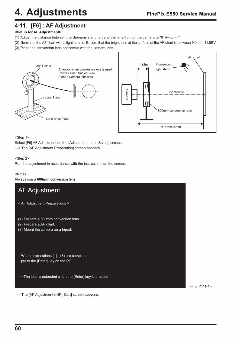
AF Adjustment
< AF Adjustment Preparations >
(1) Prepare a 600mm conversion lens.(2) Prepare a AF chart.(3) Mount the camera on a tripod.
When preparations (1) - (3) are complete, press the [Enter] key on the PC.
--> The lens is extended when the [Enter] key is pressed.
<Fig. 4-11-1>
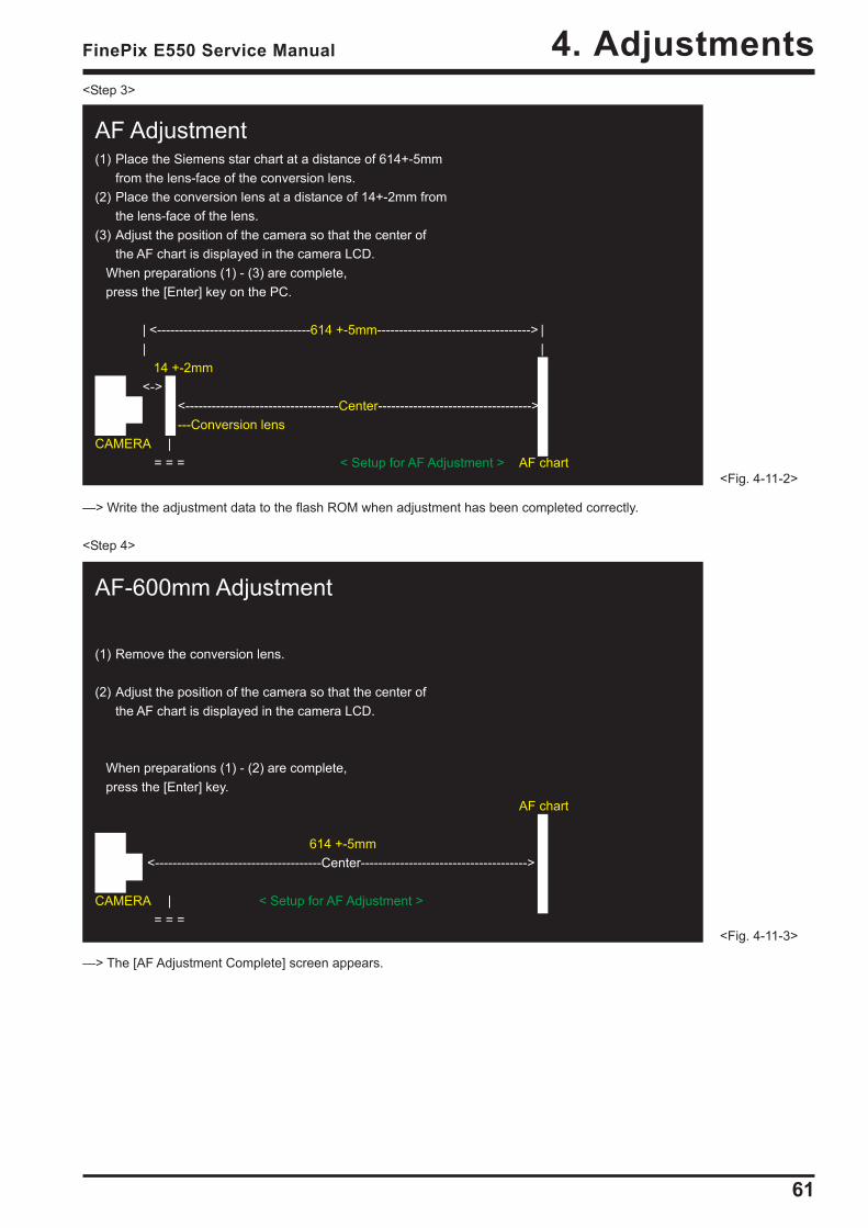
4-11. [F6] : AF Adjustment<Setup for AF Adjustment>(1) Adjust the distance between the Siemens star chart and the lens front of the camera to "614+-5mm"(2) Illuminate the AF chart with a light source. Ensure that the brightness at the surface of the AF chart is between 9.0 and 11.5EV.(3) Place the conversion lens concentric with the camera lens.
<Step 1>Select [F6] AF Adjustment on the [Adjustment Items Select] screen.—> The [AF Adjustment Preparation] screen appears.
<Step 2>Run the adjustment in accordance with the instructions on the screen.
<Note>Always use a 600mm conversion lens.
—> The [AF Adjustment (INF) Start] screen appears.
Lens Holder
Lens Base Plate
Lens Stand
Attention when conversion lens is used.
Convex side : Subject side.
Plane : Camera lens side.
614mm±5mm
AF chart
14±2mm Fluorescentlight stand
Centerline
Cam
era600mm conversion lens
61
4. AdjustmentsFinePix E550 Service Manual
<Step 3>
—> Write the adjustment data to the flash ROM when adjustment has been completed correctly.
<Step 4>
—> The [AF Adjustment Complete] screen appears.
AF-600mm Adjustment
(1) Remove the conversion lens.
(2) Adjust the position of the camera so that the center ofthe AF chart is displayed in the camera LCD.
When preparations (1) - (2) are complete, press the [Enter] key.
AF chart
614 +-5mm<--------------------------------------Center-------------------------------------->
CAMERA | < Setup for AF Adjustment >= = =
<Fig. 4-11-3>
AF Adjustment(1) Place the Siemens star chart at a distance of 614+-5mm
from the lens-face of the conversion lens.(2) Place the conversion lens at a distance of 14+-2mm from
the lens-face of the lens.(3) Adjust the position of the camera so that the center of
the AF chart is displayed in the camera LCD. When preparations (1) - (3) are complete, press the [Enter] key on the PC.
| <-----------------------------------614 +-5mm-----------------------------------> || | 14 +-2mm<->
<-----------------------------------Center----------------------------------->---Conversion lens
CAMERA |= = = < Setup for AF Adjustment > AF chart
<Fig. 4-11-2>
62
4. Adjustments FinePix E550 Service Manual
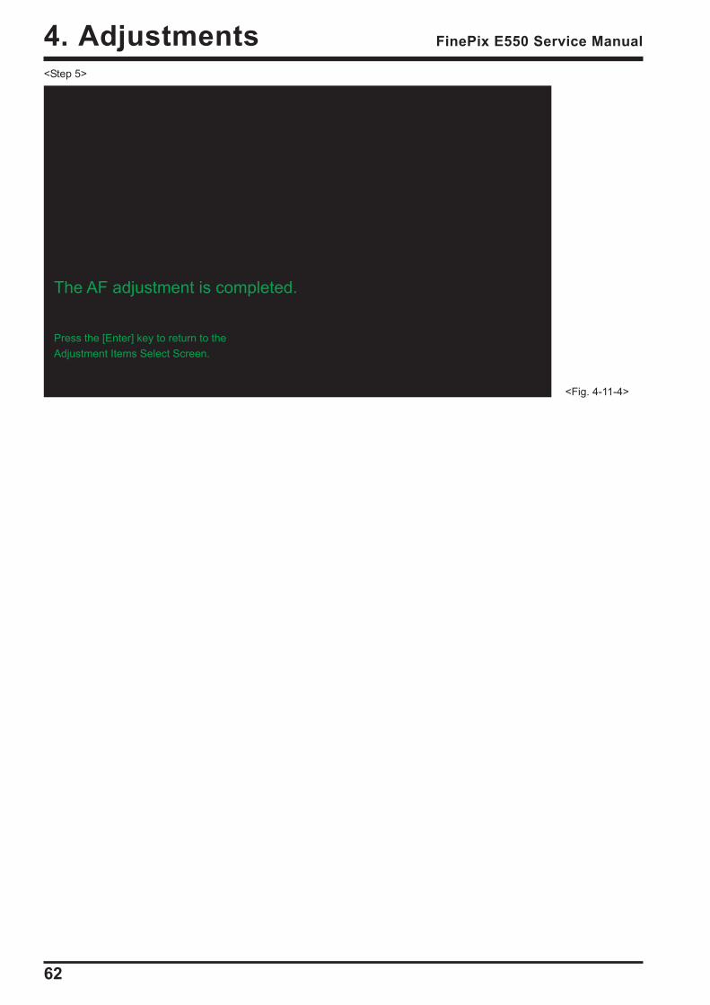
<Fig. 4-11-4>
<Step 5>
The AF adjustment is completed.
Press the [Enter] key to return to theAdjustment Items Select Screen.
63
4. AdjustmentsFinePix E550 Service Manual
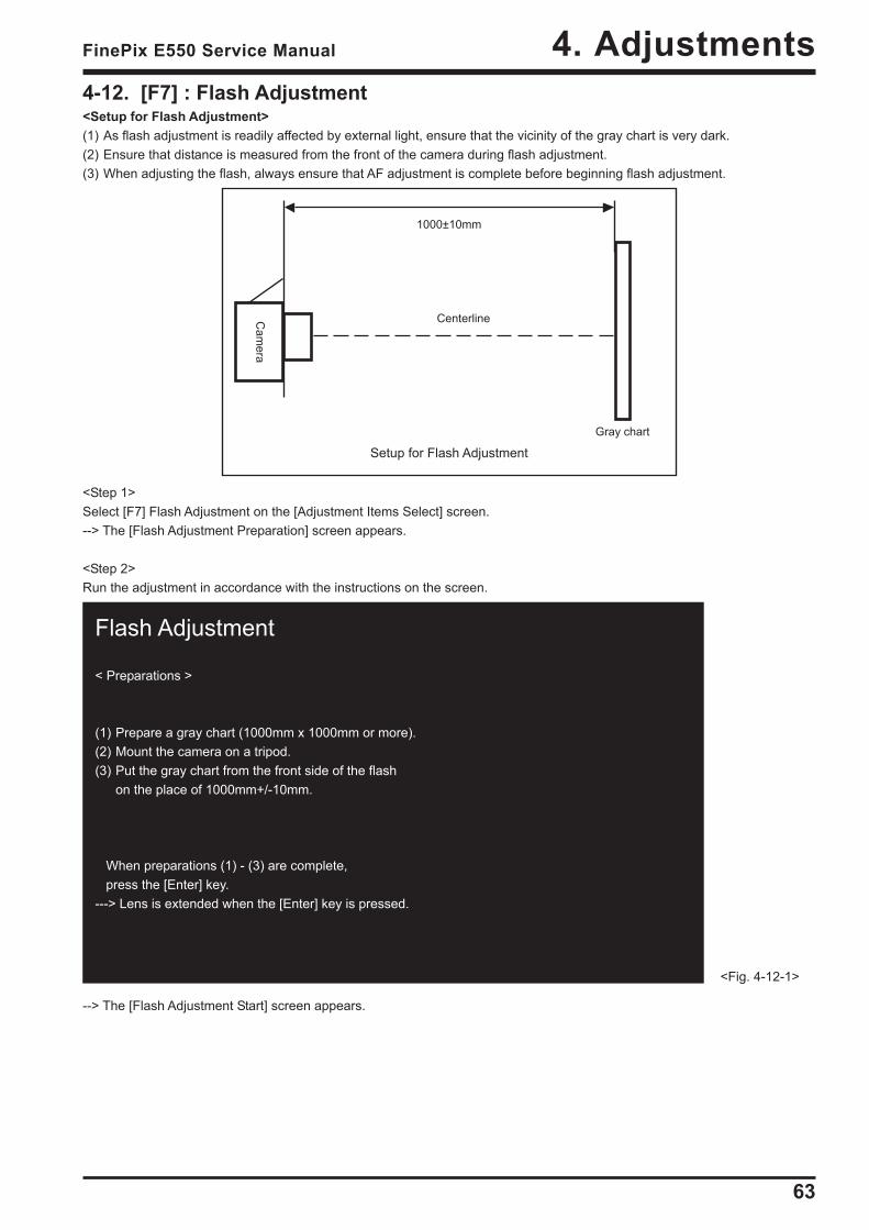
Flash Adjustment
< Preparations >
(1) Prepare a gray chart (1000mm x 1000mm or more).(2) Mount the camera on a tripod.(3) Put the gray chart from the front side of the flash
on the place of 1000mm+/-10mm.
When preparations (1) - (3) are complete, press the [Enter] key.---> Lens is extended when the [Enter] key is pressed.
<Fig. 4-12-1>
4-12. [F7] : Flash Adjustment<Setup for Flash Adjustment>(1) As flash adjustment is readily affected by external light, ensure that the vicinity of the gray chart is very dark.(2) Ensure that distance is measured from the front of the camera during flash adjustment.(3) When adjusting the flash, always ensure that AF adjustment is complete before beginning flash adjustment.
Setup for Flash AdjustmentGray chart
1000±10mm
Centerline
<Step 1>Select [F7] Flash Adjustment on the [Adjustment Items Select] screen.--> The [Flash Adjustment Preparation] screen appears.
<Step 2>Run the adjustment in accordance with the instructions on the screen.
--> The [Flash Adjustment Start] screen appears.
Cam
era
64
4. Adjustments FinePix E550 Service Manual
<Step 3>
--> Write the adjustment data to the flash ROM when adjustment has been completed correctly.--> The [Flash Adjustment Complete] screen appears.
<Step 4>
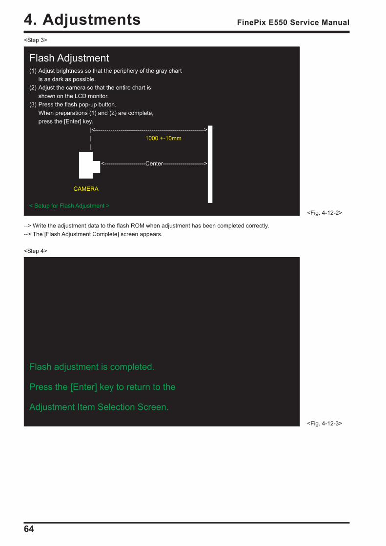
Flash Adjustment(1) Adjust brightness so that the periphery of the gray chart
is as dark as possible.(2) Adjust the camera so that the entire chart is
shown on the LCD monitor.(3) Press the flash pop-up button.
When preparations (1) and (2) are complete,press the [Enter] key.
|<-------------------------------------------------------->| 1000 +-10mm|
<---------------------Center--------------------->
CAMERA
< Setup for Flash Adjustment ><Fig. 4-12-2>
Flash adjustment is completed.
Press the [Enter] key to return to the
Adjustment Item Selection Screen.
<Fig. 4-12-3>
65
4. AdjustmentsFinePix E550 Service Manual
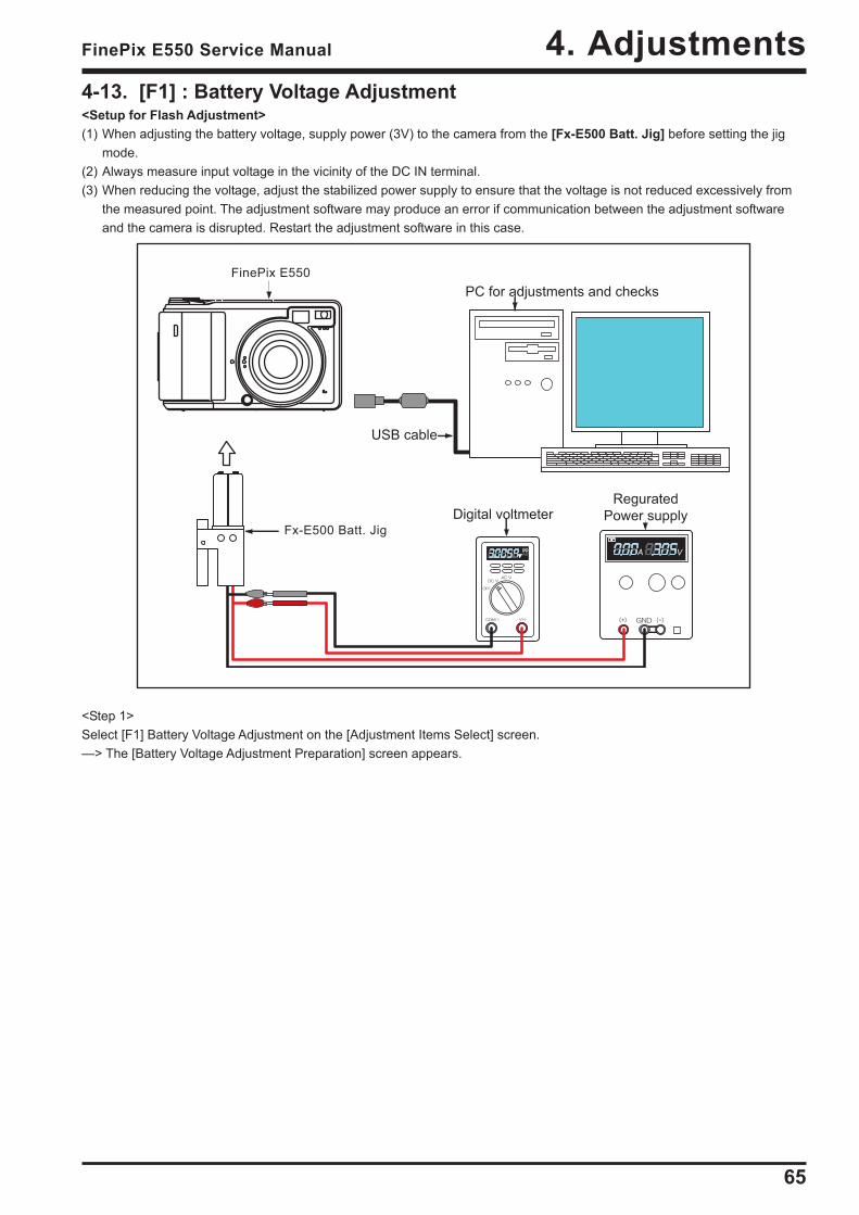
4-13. [F1] : Battery Voltage Adjustment<Setup for Flash Adjustment>(1) When adjusting the battery voltage, supply power (3V) to the camera from the [Fx-E500 Batt. Jig] before setting the jig
mode.(2) Always measure input voltage in the vicinity of the DC IN terminal.(3) When reducing the voltage, adjust the stabilized power supply to ensure that the voltage is not reduced excessively from
the measured point. The adjustment software may produce an error if communication between the adjustment softwareand the camera is disrupted. Restart the adjustment software in this case.
<Step 1>Select [F1] Battery Voltage Adjustment on the [Adjustment Items Select] screen.—> The [Battery Voltage Adjustment Preparation] screen appears.
FinePix E550
Fx-E500 Batt. Jig
66
4. Adjustments FinePix E550 Service Manual
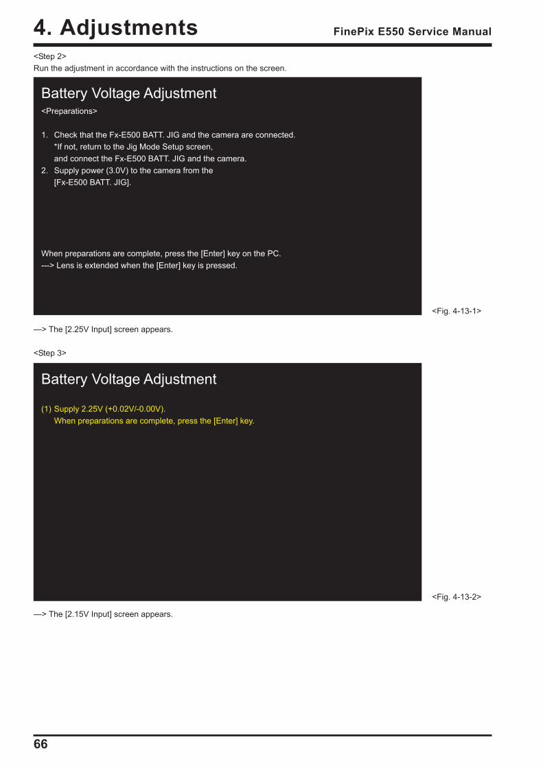
Battery Voltage Adjustment
(1) Supply 2.25V (+0.02V/-0.00V).When preparations are complete, press the [Enter] key.
<Fig. 4-13-2>
Battery Voltage Adjustment<Preparations>
1. Check that the Fx-E500 BATT. JIG and the camera are connected.*If not, return to the Jig Mode Setup screen,and connect the Fx-E500 BATT. JIG and the camera.
2. Supply power (3.0V) to the camera from the[Fx-E500 BATT. JIG].
When preparations are complete, press the [Enter] key on the PC.---> Lens is extended when the [Enter] key is pressed.
<Fig. 4-13-1>
<Step 2>Run the adjustment in accordance with the instructions on the screen.
—> The [2.25V Input] screen appears.
<Step 3>
—> The [2.15V Input] screen appears.
67
4. AdjustmentsFinePix E550 Service Manual
<Fig. 4-13-4>
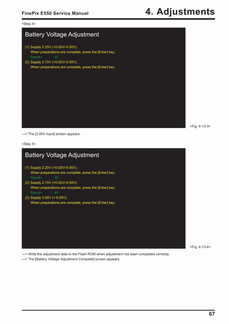
Battery Voltage Adjustment
(1) Supply 2.25V (+0.02V/-0.00V).When preparations are complete, press the [Enter] key.Result= 4C
(2) Supply 2.15V (+0.02V/-0.00V).When preparations are complete, press the [Enter] key.Result= 49
(3) Supply 3.00V (+-0.05V).When preparations are complete, press the [Enter] key.
<Fig. 4-13-3>
Battery Voltage Adjustment
(1) Supply 2.25V (+0.02V/-0.00V).When preparations are complete, press the [Enter] key.Result= 4C
(2) Supply 2.15V (+0.02V/-0.00V).When preparations are complete, press the [Enter] key.
<Step 4>
—> The [3.00V Input] screen appears.
<Step 5>
—> Write the adjustment data to the Flash ROM when adjustment has been completed correctly.—> The [Battery Voltage Adjustment Complete] screen appears.

68
4. Adjustments FinePix E550 Service Manual
<Fig. 4-13-5>
The BATTERY adjustment is completed.
Press the [Enter] key to return to theAdjustment Item selection Screen.
<Step 6>
69
4. AdjustmentsFinePix E550 Service Manual
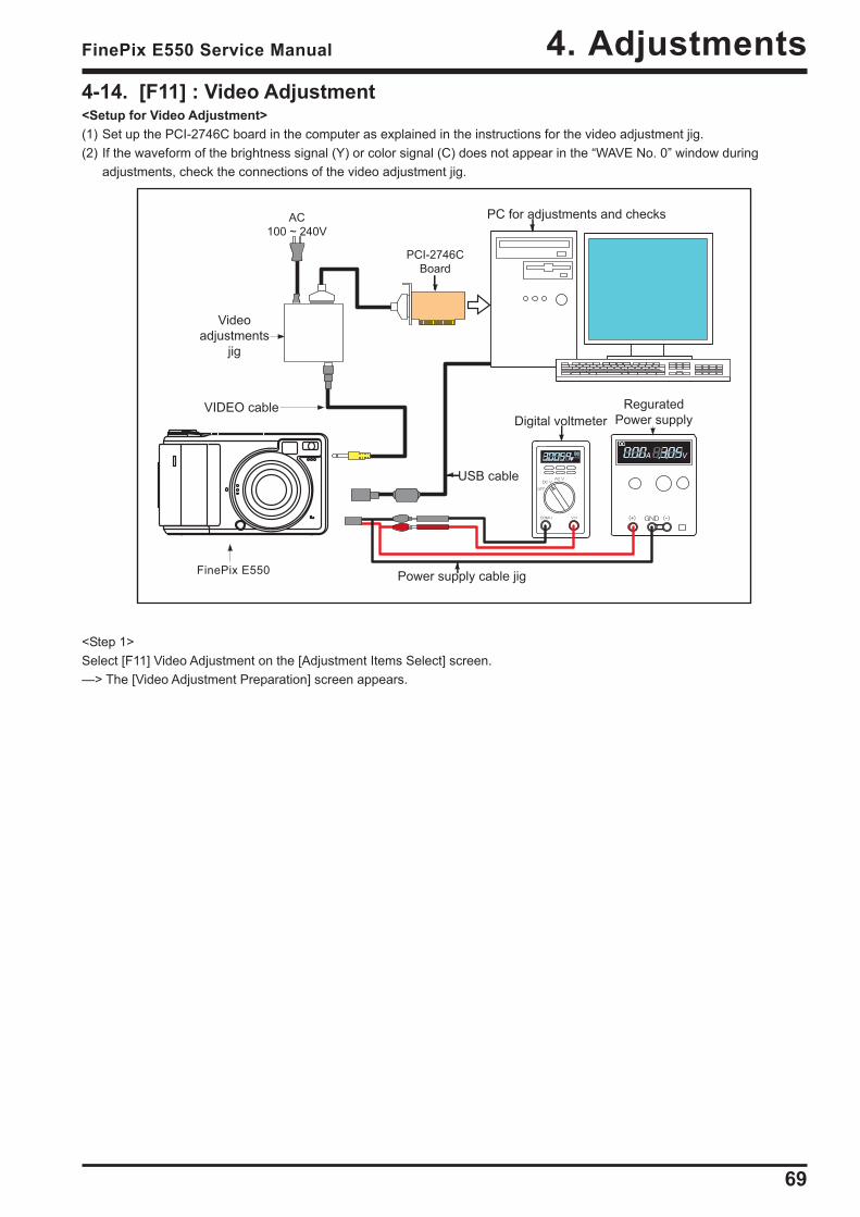
4-14. [F11] : Video Adjustment<Setup for Video Adjustment>(1) Set up the PCI-2746C board in the computer as explained in the instructions for the video adjustment jig.(2) If the waveform of the brightness signal (Y) or color signal (C) does not appear in the “WAVE No. 0” window during
adjustments, check the connections of the video adjustment jig.
<Step 1>Select [F11] Video Adjustment on the [Adjustment Items Select] screen.—> The [Video Adjustment Preparation] screen appears.
FinePix E550
PCI-2746C
Board
AC
100 ~ 240V
70
4. Adjustments FinePix E550 Service Manual
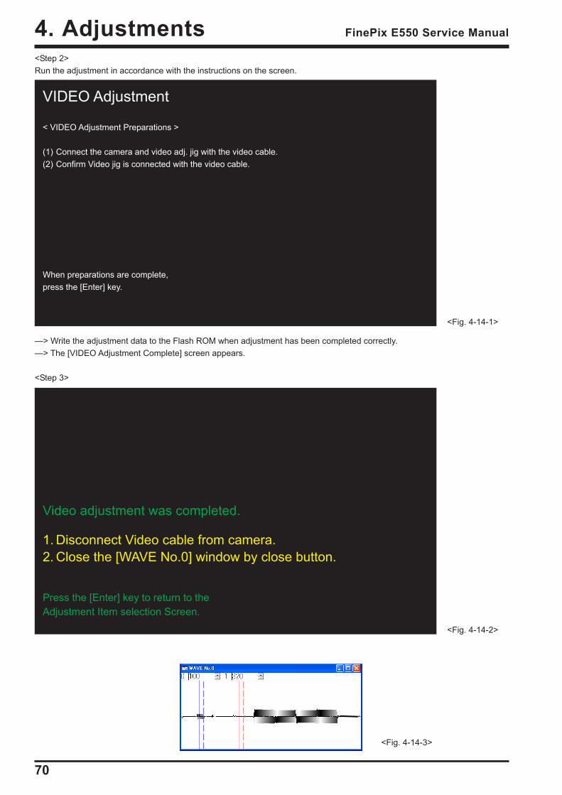
Video adjustment was completed.
1. Disconnect Video cable from camera.2. Close the [WAVE No.0] window by close button.
Press the [Enter] key to return to theAdjustment Item selection Screen.
<Fig. 4-14-2>
VIDEO Adjustment
< VIDEO Adjustment Preparations >
(1) Connect the camera and video adj. jig with the video cable.(2) Confirm Video jig is connected with the video cable.
When preparations are complete,press the [Enter] key.
<Fig. 4-14-1>
<Fig. 4-14-3>
<Step 2>Run the adjustment in accordance with the instructions on the screen.
—> Write the adjustment data to the Flash ROM when adjustment has been completed correctly.—> The [VIDEO Adjustment Complete] screen appears.
<Step 3>
71
4. AdjustmentsFinePix E550 Service Manual
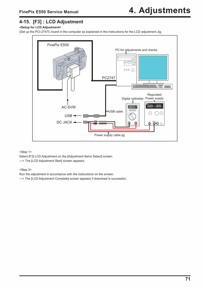
4-15. [F3] : LCD Adjustment<Setup for LCD Adjustment>(Set up the PCI-2747C board in the computer as explained in the instructions for the LCD adjustment Jig.
<Step 1>Select [F3] LCD Adjustment on the [Adjustment Items Select] screen.—> The [LCD Adjustment Start] screen appears.
<Step 2>Run the adjustment in accordance with the instructions on the screen.—> The [LCD Adjustment Complete] screen appears if download is successful.
FinePix E550
AC-5VW
PC2747
USB
DC JACK
72
4. Adjustments FinePix E550 Service Manual
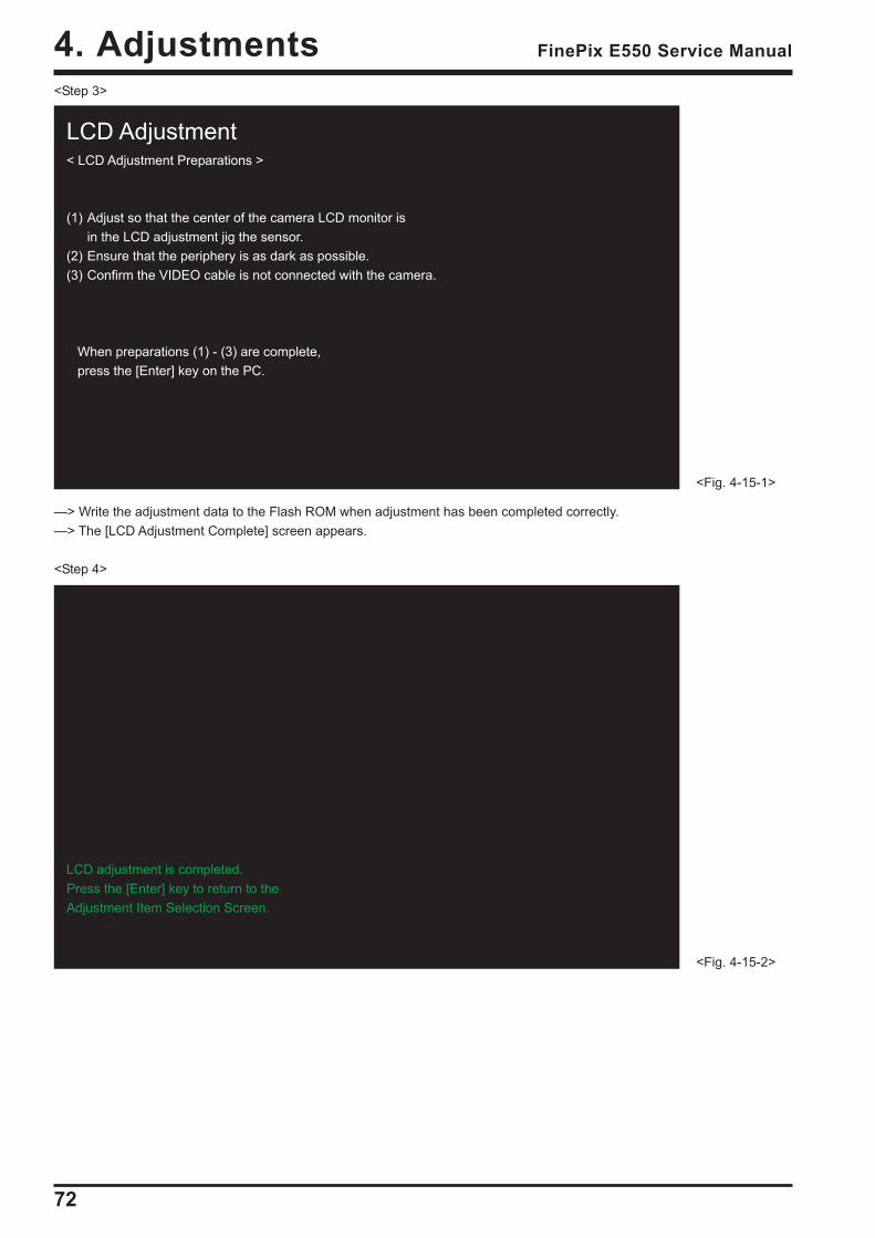
LCD adjustment is completed.Press the [Enter] key to return to theAdjustment Item Selection Screen.
<Fig. 4-15-2>
LCD Adjustment< LCD Adjustment Preparations >
(1) Adjust so that the center of the camera LCD monitor isin the LCD adjustment jig the sensor.
(2) Ensure that the periphery is as dark as possible.(3) Confirm the VIDEO cable is not connected with the camera.
When preparations (1) - (3) are complete, press the [Enter] key on the PC.
<Fig. 4-15-1>
<Step 3>
—> Write the adjustment data to the Flash ROM when adjustment has been completed correctly.—> The [LCD Adjustment Complete] screen appears.
<Step 4>
73
4. AdjustmentsFinePix E550 Service Manual
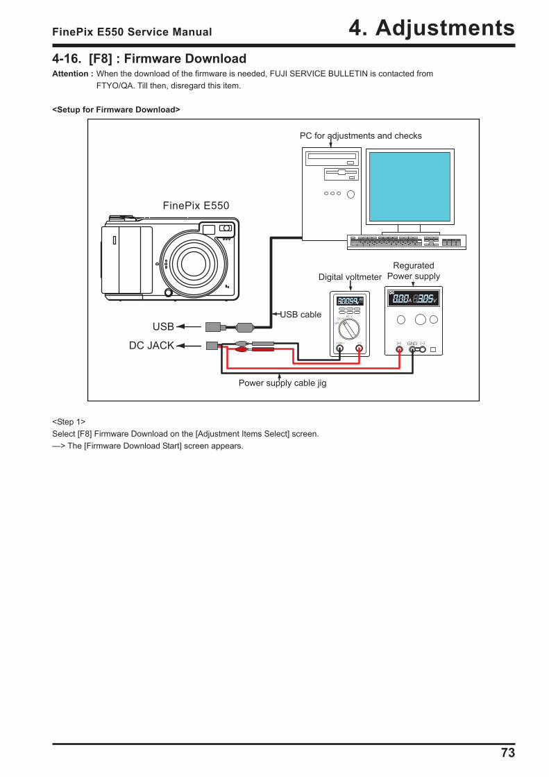
4-16. [F8] : Firmware DownloadAttention : When the download of the firmware is needed, FUJI SERVICE BULLETIN is contacted from
FTYO/QA. Till then, disregard this item.
<Setup for Firmware Download>
<Step 1>Select [F8] Firmware Download on the [Adjustment Items Select] screen.—> The [Firmware Download Start] screen appears.
USB
DC JACK
FinePix E550
74
4. Adjustments FinePix E550 Service Manual
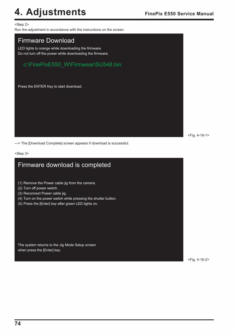
Firmware download is completed
(1) Remove the Power cable jig from the camera.(2) Turn off power switch.(3) Reconnect Power cable jig.(4) Turn on the power switch while pressing the shutter button.(5) Press the [Enter] key after green LED lights on.
The system returns to the Jig Mode Setup screenwhen press the [Enter] key.
<Fig. 4-16-2>
Firmware DownloadLED lights to orange while downloading the firmware.Do not turn off the power while downloading the firmware.
c:\FinePixE550_W\Firmwear\SU548.bin
Press the ENTER Key to start download.
<Fig. 4-16-1>
<Step 2>Run the adjustment in accordance with the instructions on the screen.
—> The [Download Complete] screen appears if download is successful.
<Step 3>
75
4. AdjustmentsFinePix E550 Service Manual
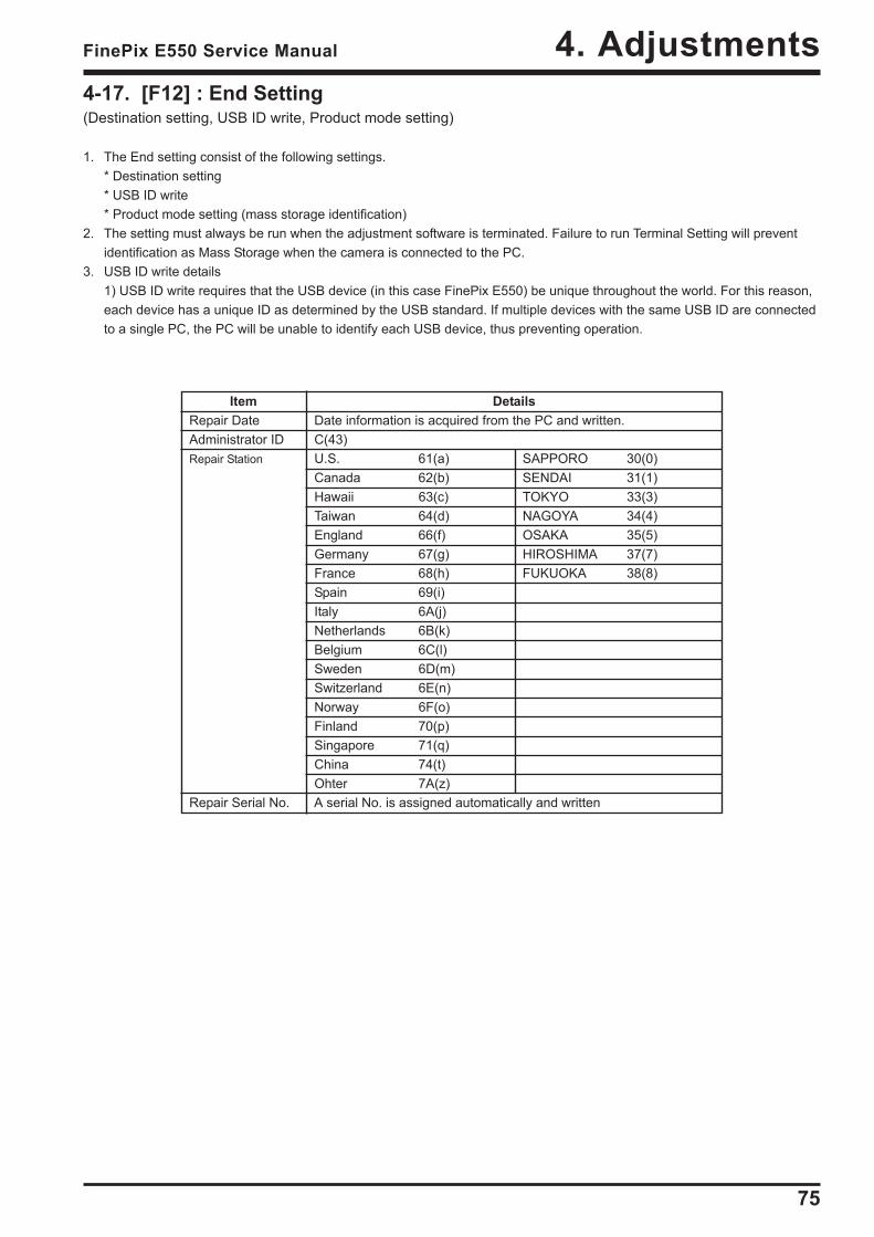
4-17. [F12] : End Setting(Destination setting, USB ID write, Product mode setting)
1. The End setting consist of the following settings.* Destination setting* USB ID write* Product mode setting (mass storage identification)
2. The setting must always be run when the adjustment software is terminated. Failure to run Terminal Setting will preventidentification as Mass Storage when the camera is connected to the PC.
3. USB ID write details1) USB ID write requires that the USB device (in this case FinePix E550) be unique throughout the world. For this reason,each device has a unique ID as determined by the USB standard. If multiple devices with the same USB ID are connectedto a single PC, the PC will be unable to identify each USB device, thus preventing operation.
Item DetailsRepair Date Date information is acquired from the PC and written.Administrator ID C(43)Repair Station U.S. 61(a) SAPPORO 30(0)
Canada 62(b) SENDAI 31(1)Hawaii 63(c) TOKYO 33(3)Taiwan 64(d) NAGOYA 34(4)England 66(f) OSAKA 35(5)Germany 67(g) HIROSHIMA 37(7)France 68(h) FUKUOKA 38(8)Spain 69(i)Italy 6A(j)Netherlands 6B(k)Belgium 6C(l)Sweden 6D(m)Switzerland 6E(n)Norway 6F(o)Finland 70(p)Singapore 71(q)China 74(t)Ohter 7A(z)
Repair Serial No. A serial No. is assigned automatically and written

76
4. Adjustments FinePix E550 Service Manual
Destination settingThe destination is selected from an undermentioned list,according to third character from left side of the serial number.
The third character<A> FinePix E550 JP-model 0 to 9<B> FinePix E550 US/CA-model A to H,J,K<C> FinePix E550 EU/EG/GE/AS-model L to N,P to V<D> FinePix E550 CH-model W to Z
<Fig. 4-17-2>
End Setting
The End settings consist of the destination setting,the USB_ID write, and product mode settings(= Mass Storage recognition).
Press the [Enter] key.
<Fig. 4-17-1>
<Step 1>Select [F12] End Setting on the [Adjustment Items Select] screen.—> The [End Setting Description] screen appears.
<Step 2>Run the adjustment in accordance with the instructions on the screen.
—> The [Destination Setting] screen appears.
<Step 3>
<Note>This example assumes that <B>US-Model has been selected. The following screen therefore appears.—> The [US-Model selected] screen appears.
Revised: 31. Oct. 2005
77
4. AdjustmentsFinePix E550 Service Manual
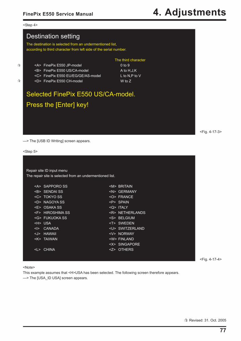
Destination settingThe destination is selected from an undermentioned list,according to third character from left side of the serial number.
The third character<A> FinePix E550 JP-model 0 to 9<B> FinePix E550 US/CA-model A to H,J,K<C> FinePix E550 EU/EG/GE/AS-model L to N,P to V<D> FinePix E550 CH-model W to Z
Selected FinePix E550 US/CA-model.Press the [Enter] key!
<Fig. 4-17-3>
Repair site ID input menuThe repair site is selected from an undermentioned list.
<A> SAPPORO SS <M> BRITAIN<B> SENDAI SS <N> GERMANY<C> TOKYO SS <O> FRANCE<D> NAGOYA SS <P> SPAIN<E> OSAKA SS <Q> ITALY<F> HIROSHIMA SS <R> NETHERLANDS<G> FUKUOKA SS <S> BELGIUM<H> USA <T> SWEDEN<I> CANADA <U> SWITZERLAND<J> HAWAII <V> NORWAY<K> TAIWAN <W> FINLAND
<X> SINGAPORE<L> CHINA <Z> OTHERS
<Fig. 4-17-4>
<Step 4>
—> The [USB ID Writing] screen appears.
<Step 5>
<Note>This example assumes that <H>USA has been selected. The following screen therefore appears.—> The [USA_ID USA] screen appears.
Revised: 31. Oct. 2005
78
4. Adjustments FinePix E550 Service Manual
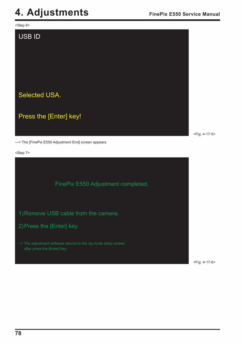
<Step 6>
—> The [FinePix E550 Adjustment End] screen appears.
<Step 7>
USB ID
Selected USA.
Press the [Enter] key!
<Fig. 4-17-5>
<Fig. 4-17-6>
FinePix E550 Adjustment completed.
1)Remove USB cable from the camera.
2)Press the [Enter] key.
--> The adjustment software returns to the Jig mode setup screenafter press the [Enter] key.
79
5. InspectionFinePix E550 Service Manual
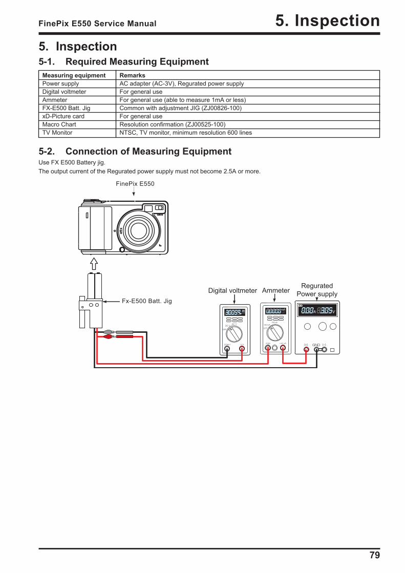
5. Inspection5-1. Required Measuring Equipment
Measuring equipment RemarksPower supply AC adapter (AC-3V), Regurated power supplyDigital voltmeter For general useAmmeter For general use (able to measure 1mA or less)FX-E500 Batt. Jig Common with adjustment JIG (ZJ00826-100)xD-Picture card For general useMacro Chart Resolution confirmation (ZJ00525-100)TV Monitor NTSC, TV monitor, minimum resolution 600 lines
5-2. Connection of Measuring EquipmentUse FX E500 Battery jig.The output current of the Regurated power supply must not become 2.5A or more.
FinePix E550
Fx-E500 Batt. Jig
Ammeter
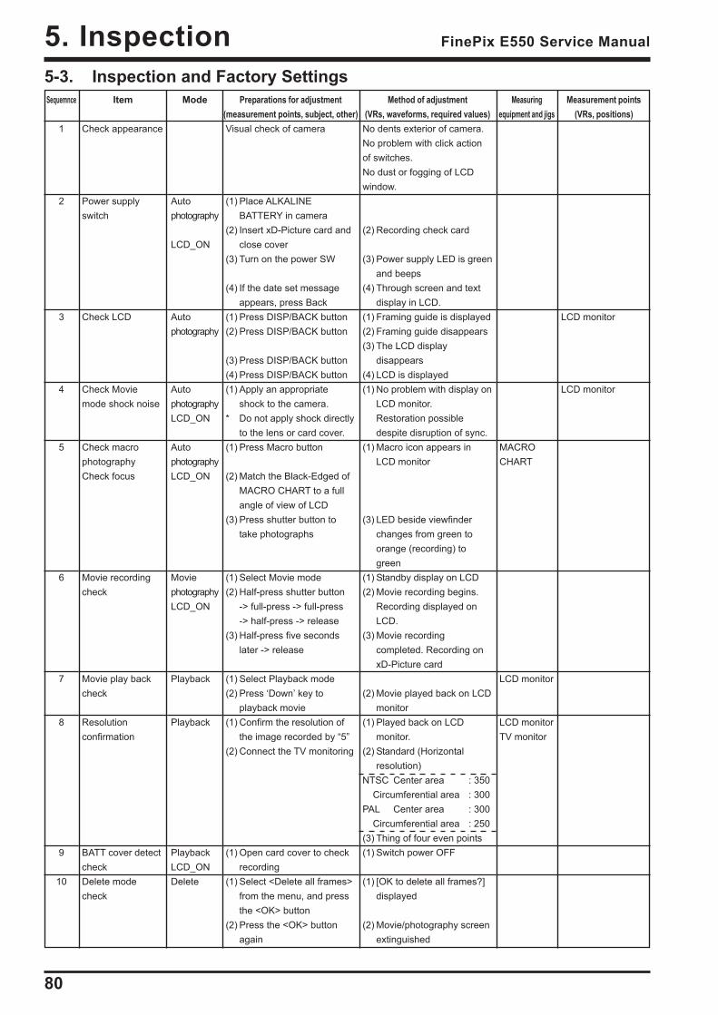
80
5. Inspection FinePix E550 Service Manual
5-3. Inspection and Factory SettingsSequemnce Item Mode Preparations for adjustment
(measurement points, subject, other)Method of adjustment
(VRs, waveforms, required values)Measuring
equipment and jigsMeasurement points
(VRs, positions)1
2
3
4
5
6
7
8
9
10
Check appearance
Power supplyswitch
Check LCD
Check Moviemode shock noise
Check macrophotographyCheck focus
Movie recordingcheck
Movie play backcheck
Resolutionconfirmation
BATT cover detectcheckDelete modecheck
Autophotography
LCD_ON
Autophotography
AutophotographyLCD_ON
AutophotographyLCD_ON
MoviephotographyLCD_ON
Playback
Playback
PlaybackLCD_ONDelete
Visual check of camera
(1) Place ALKALINEBATTERY in camera
(2) Insert xD-Picture card andclose cover
(3) Turn on the power SW
(4) If the date set messageappears, press Back
(1) Press DISP/BACK button(2) Press DISP/BACK button
(3) Press DISP/BACK button(4) Press DISP/BACK button(1) Apply an appropriate
shock to the camera.* Do not apply shock directly
to the lens or card cover.(1) Press Macro button
(2) Match the Black-Edged ofMACRO CHART to a fullangle of view of LCD
(3) Press shutter button totake photographs
(1) Select Movie mode(2) Half-press shutter button
-> full-press -> full-press-> half-press -> release
(3) Half-press five secondslater -> release
(1) Select Playback mode(2) Press ‘Down’ key to
playback movie(1) Confirm the resolution of
the image recorded by “5”(2) Connect the TV monitoring
(1) Open card cover to checkrecording
(1) Select <Delete all frames>from the menu, and pressthe <OK> button
(2) Press the <OK> buttonagain
No dents exterior of camera.No problem with click actionof switches.No dust or fogging of LCDwindow.
(2) Recording check card
(3) Power supply LED is greenand beeps
(4) Through screen and textdisplay in LCD.
(1) Framing guide is displayed(2) Framing guide disappears(3) The LCD display
disappears(4) LCD is displayed(1) No problem with display on
LCD monitor.Restoration possibledespite disruption of sync.
(1) Macro icon appears inLCD monitor
(3) LED beside viewfinderchanges from green toorange (recording) togreen
(1) Standby display on LCD(2) Movie recording begins.
Recording displayed onLCD.
(3) Movie recordingcompleted. Recording onxD-Picture card
(2) Movie played back on LCDmonitor
(1) Played back on LCDmonitor.
(2) Standard (Horizontalresolution)
NTSC Center area : 350Circumferential area : 300
PAL Center area : 300Circumferential area : 250
(3) Thing of four even points(1) Switch power OFF
(1) [OK to delete all frames?]displayed
(2) Movie/photography screenextinguished
MACROCHART
LCD monitor
LCD monitorTV monitor
LCD monitor
LCD monitor
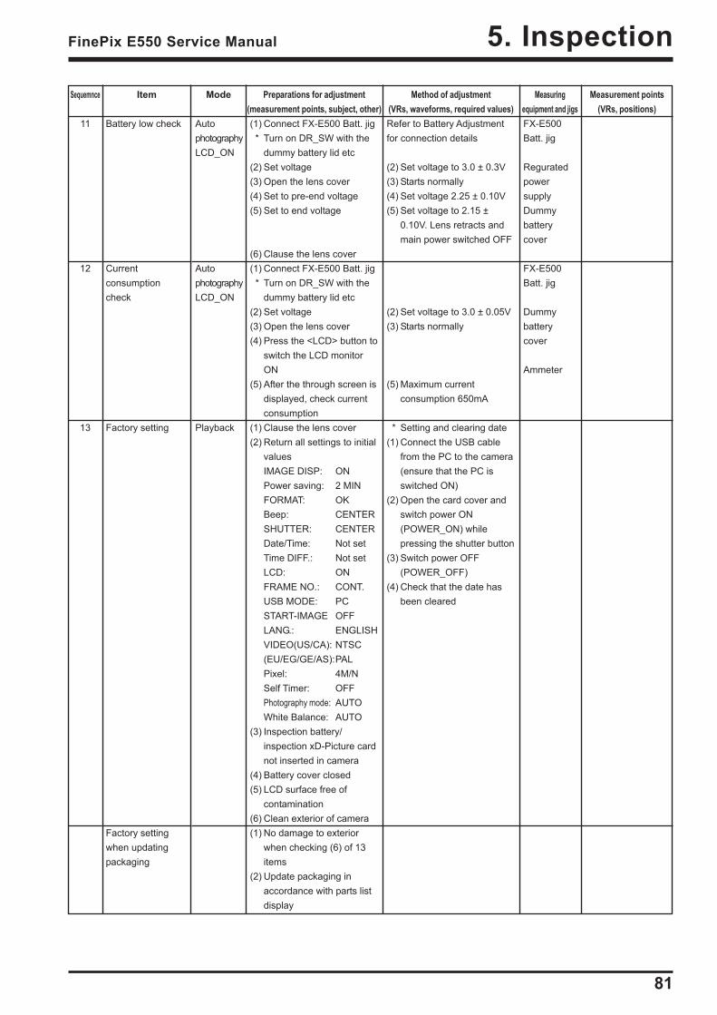
81
5. InspectionFinePix E550 Service Manual
Sequemnce Item Mode Preparations for adjustment(measurement points, subject, other)
Method of adjustment(VRs, waveforms, required values)
Measuringequipment and jigs
Measurement points(VRs, positions)
11
12
13
Battery low check
Currentconsumptioncheck
Factory setting
Factory settingwhen updatingpackaging
AutophotographyLCD_ON
AutophotographyLCD_ON
Playback
(1) Connect FX-E500 Batt. jig * Turn on DR_SW with the
dummy battery lid etc(2) Set voltage(3) Open the lens cover(4) Set to pre-end voltage(5) Set to end voltage
(6) Clause the lens cover(1) Connect FX-E500 Batt. jig * Turn on DR_SW with the
dummy battery lid etc(2) Set voltage(3) Open the lens cover(4) Press the <LCD> button to
switch the LCD monitorON
(5) After the through screen isdisplayed, check currentconsumption
(1) Clause the lens cover(2) Return all settings to initial
valuesIMAGE DISP: ONPower saving: 2 MINFORMAT: OKBeep: CENTERSHUTTER: CENTERDate/Time: Not setTime DIFF.: Not setLCD: ONFRAME NO.: CONT.USB MODE: PCSTART-IMAGE OFFLANG.: ENGLISHVIDEO(US/CA): NTSC(EU/EG/GE/AS):PALPixel: 4M/NSelf Timer: OFFPhotography mode: AUTOWhite Balance: AUTO
(3) Inspection battery/inspection xD-Picture cardnot inserted in camera
(4) Battery cover closed(5) LCD surface free of
contamination(6) Clean exterior of camera(1) No damage to exterior
when checking (6) of 13items
(2) Update packaging inaccordance with parts listdisplay
Refer to Battery Adjustmentfor connection details
(2) Set voltage to 3.0 ± 0.3V(3) Starts normally(4) Set voltage 2.25 ± 0.10V(5) Set voltage to 2.15 ±
0.10V. Lens retracts andmain power switched OFF
(2) Set voltage to 3.0 ± 0.05V(3) Starts normally
(5) Maximum currentconsumption 650mA
* Setting and clearing date(1) Connect the USB cable
from the PC to the camera(ensure that the PC isswitched ON)
(2) Open the card cover andswitch power ON(POWER_ON) whilepressing the shutter button
(3) Switch power OFF(POWER_OFF)
(4) Check that the date hasbeen cleared
FX-E500Batt. jig
ReguratedpowersupplyDummybatterycover
FX-E500Batt. jig
Dummybatterycover
Ammeter
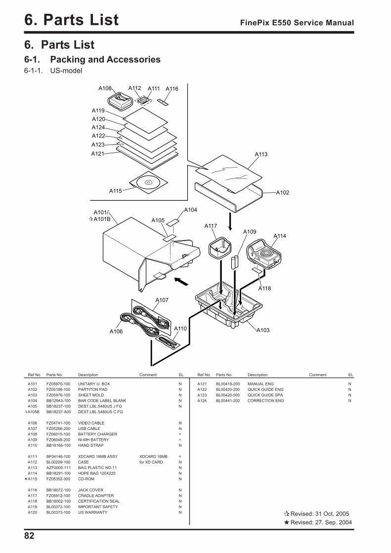
82
6. Parts List FinePix E550 Service Manual
6. Parts List6-1. Packing and Accessories6-1-1. US-model
A101 FZ05970-100 UNITARY U. BOX NA102 FZ05186-100 PARTITON PAD NA103 FZ05976-100 SHEET MOLD NA104 BB12943-100 BAR CODE LABEL BLANK NA105 BB18237-100 DEST.LBL.5480US J FG NA105B BB18237-A00 DEST.LBL.5480US C FG
A106 FZ04741-100 VIDEO CABLE NA107 FZ05266-200 USB CABLE NA108 FZ06015-100 BATTERY CHARGER =A109 FZ06048-200 NI-MH BATTERY =A110 BB18166-100 HAND STRAP N
A111 BF04146-100 XDCARD 16MB ASSY XDCARD 16MB =A112 BL00209-100 CASE for XD CARD NA113 AZF0000-111 BAG PLASTIC NO.11 NA114 BB18291-100 HDPE BAG 120X220 NA115 FZ05352-300 CD-ROM N
A116 BB18072-100 JACK COVER NA117 FZ05912-100 CRADLE ADAPTER NA118 BB18002-100 CERTIFICATION SEAL NA119 BL00372-100 IMPORTANT SAFETY NA120 BL00373-100 US WARRANTY N
Ref No. Parts No. Description Comment EL Ref No. Parts No. Description Comment EL
A119
A120
A122
A123
A121
A124
A102
A103
A104
A105
A106
A107
A108
A109
A110
A111A112
A113
A114
A115
A116
A117
A118
A101/
A101B
A121 BL00419-200 MANUAL ENG NA122 BL00420-200 QUICK GUIDE ENG NA123 BL00420-500 QUICK GUIDE SPA NA124 BL00441-200 CORRECTION ENG N
Revised: 31 Oct. 2005Revised: 27. Sep. 2004

83
6. Parts ListFinePix E550 Service Manual
6-1-2. CA-model
A119
A120
A122
A121
A123
A102
A103
A104
A105
A106
A107
A108
A109
A110
A111A112
A113
A114
A115
A116
A117
A118
A101/
A101B
A101 FZ05970-100 UNITARY U. BOX NA102 FZ05186-100 PARTITON PAD NA103 FZ05976-100 SHEET MOLD NA104 BB12943-100 BAR CODE LABEL BLANK NA105 BB18237-400 DEST.LBL.5480CA J FG NA105B BB18237-D00 DEST.LBL.5480CA C FG
A106 FZ04741-100 VIDEO CABLE NA107 FZ05266-200 USB CABLE NA108 FZ06015-100 BATTERY CHARGER =A109 FZ06048-200 NI-MH BATTERY =A110 BB18166-100 HAND STRAP N
A111 BF04146-100 XDCARD 16MB ASSY XDCARD 16MB =A112 BL00209-100 CASE for XD CARD NA113 AZF0000-111 BAG PLASTIC NO.11 NA114 BB18291-100 HDPE BAG 120X220 NA115 FZ05352-300 CD-ROM N
A116 BB18072-100 JACK COVER NA117 FZ05912-100 CRADLE ADAPTER NA118 BB18002-100 CERTIFICATION SEAL NA119 BL00419-200 MANUAL ENG NA120 BL00419-300 MANUAL FRE N
A121 BL00420-200 QUICK GUIDE ENG NA122 BL00420-300 QUICK GUIDE FRE NA123 BL00441-200 CORRECTION ENG NA124 BL00441-300 CORRECTION FRE N
Ref No. Parts No. Description Comment EL Ref No. Parts No. Description Comment EL
Revised: 31. Oct. 2005Revised: 27. Sep. 2004
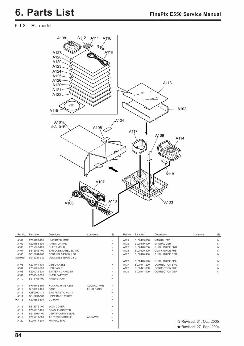
84
6. Parts List FinePix E550 Service Manual
6-1-3. EU-model
Ref No. Parts No. Description Comment EL Ref No. Parts No. Description Comment EL
A119
A120
A122
A121
A123
A125
A124
A126
A127
A128
A129
A102
A103
A104
A105
A106
A107
A108
A109
A110
A111A112
A113
A114
A115
A116
A117
A118
A101/
A101B
A101 FZ05970-100 UNITARY U. BOX NA102 FZ05186-100 PARTITON PAD NA103 FZ05976-100 SHEET MOLD NA104 BB12943-100 BAR CODE LABEL BLANK NA105 BB18237-200 DEST.LBL.5480EU J FG NA105B BB18237-B00 DEST.LBL.5480EU C FG
A106 FZ04741-100 VIDEO CABLE NA107 FZ05266-200 USB CABLE NA108 FZ06015-200 BATTERY CHARGER =A109 FZ06048-300 NI-MH BATTERY =A110 BB18166-100 HAND STRAP N
A111 BF04146-100 XDCARD 16MB ASSY XDCARD 16MB =A112 BL00209-100 CASE for XD CARD NA113 AZF0000-111 BAG PLASTIC NO.11 NA114 BB18291-100 HDPE BAG 120X220 NA115 FZ05352-300 CD-ROM N
A116 BB18072-100 JACK COVER NA117 FZ05912-100 CRADLE ADAPTER NA118 BB18002-100 CERTIFICATION SEAL NA119 FZ05210-300 AC POWERCORD E AC-5VW E NA120 BL00419-200 MANUAL ENG N
A121 BL00419-300 MANUAL FRE NA122 BL00419-400 MANUAL GER NA123 BL00420-200 QUICK GUIDE ENG NA124 BL00420-300 QUICK GUIDE FRE NA125 BL00420-400 QUICK GUIDE GER N
A126 BL00420-500 QUICK GUIDE SPA NA127 BL00441-200 CORRECTION ENG NA128 BL00441-300 CORRECTION FRE NA129 BL00441-400 CORRECTION GER N
Revised: 31. Oct. 2005Revised: 27. Sep. 2004
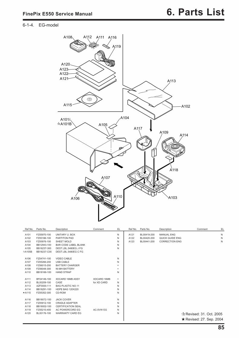
85
6. Parts ListFinePix E550 Service Manual
6-1-4. EG-model
Ref No. Parts No. Description Comment EL Ref No. Parts No. Description Comment EL
A119
A120
A122
A121
A123
A102
A103
A104
A105
A106
A107
A108
A109
A110
A111A112
A113
A114
A115
A116
A117
A118
A101/
A101B
A101 FZ05970-100 UNITARY U. BOX NA102 FZ05186-100 PARTITON PAD NA103 FZ05976-100 SHEET MOLD NA104 BB12943-100 BAR CODE LABEL BLANK NA105 BB18237-300 DEST.LBL.5480EG J FG NA105B BB18237-C00 DEST.LBL.5480EG C FG
A106 FZ04741-100 VIDEO CABLE NA107 FZ05266-200 USB CABLE NA108 FZ06015-200 BATTERY CHARGER =A109 FZ06048-300 NI-MH BATTERY =A110 BB18166-100 HAND STRAP N
A111 BF04146-100 XDCARD 16MB ASSY XDCARD 16MB =A112 BL00209-100 CASE for XD CARD NA113 AZF0000-111 BAG PLASTIC NO.11 NA114 BB18291-100 HDPE BAG 120X220 NA115 FZ05352-300 CD-ROM N
A116 BB18072-100 JACK COVER NA117 FZ05912-100 CRADLE ADAPTER NA118 BB18002-100 CERTIFICATION SEAL NA119 FZ05210-400 AC POWERCORD EG AC-5VW EG NA120 BL00176-100 WARRANTY CARD EG N
A121 BL00419-200 MANUAL ENG NA122 BL00420-200 QUICK GUIDE ENG NA123 BL00441-200 CORRECTION ENG N
Revised: 31. Oct. 2005Revised: 27. Sep. 2004
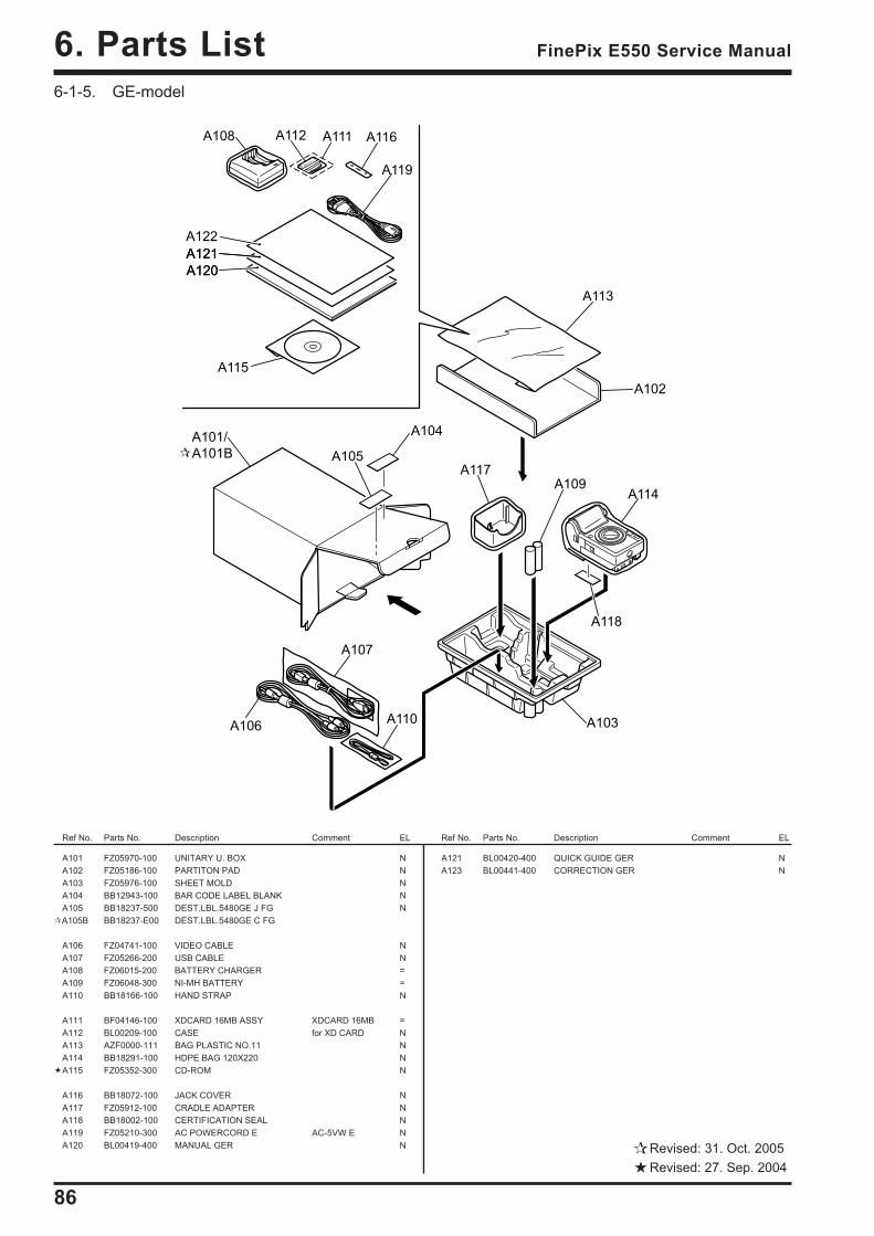
86
6. Parts List FinePix E550 Service Manual
6-1-5. GE-model
Ref No. Parts No. Description Comment EL Ref No. Parts No. Description Comment EL
A101 FZ05970-100 UNITARY U. BOX NA102 FZ05186-100 PARTITON PAD NA103 FZ05976-100 SHEET MOLD NA104 BB12943-100 BAR CODE LABEL BLANK NA105 BB18237-500 DEST.LBL.5480GE J FG NA105B BB18237-E00 DEST.LBL.5480GE C FG
A106 FZ04741-100 VIDEO CABLE NA107 FZ05266-200 USB CABLE NA108 FZ06015-200 BATTERY CHARGER =A109 FZ06048-300 NI-MH BATTERY =A110 BB18166-100 HAND STRAP N
A111 BF04146-100 XDCARD 16MB ASSY XDCARD 16MB =A112 BL00209-100 CASE for XD CARD NA113 AZF0000-111 BAG PLASTIC NO.11 NA114 BB18291-100 HDPE BAG 120X220 NA115 FZ05352-300 CD-ROM N
A116 BB18072-100 JACK COVER NA117 FZ05912-100 CRADLE ADAPTER NA118 BB18002-100 CERTIFICATION SEAL NA119 FZ05210-300 AC POWERCORD E AC-5VW E NA120 BL00419-400 MANUAL GER N
A120
A121
A119
A120
A121
A122
A102
A103
A104
A105
A106
A107
A108
A109
A110
A111A112
A113
A114
A115
A116
A117
A118
A101/
A101B
Revised: 31. Oct. 2005Revised: 27. Sep. 2004
A121 BL00420-400 QUICK GUIDE GER NA123 BL00441-400 CORRECTION GER N

87
6. Parts ListFinePix E550 Service Manual
6-1-6. AS-model
Ref No. Parts No. Description Comment EL Ref No. Parts No. Description Comment EL
A101 FZ05970-100 UNITARY U. BOX NA102 FZ05186-100 PARTITON PAD NA103 FZ05976-100 SHEET MOLD NA104 BB12943-100 BAR CODE LABEL BLANK NA105 BB18237-600 DEST.LBL.5480AS J FG NA105B BB18237-F00 DEST.LBL.5480AS C FG
A106 FZ04741-100 VIDEO CABLE NA107 FZ05266-200 USB CABLE NA108 FZ06015-200 BATTERY CHARGER =A109 FZ06048-300 NI-MH BATTERY =A110 BB18166-100 HAND STRAP N
A111 BF04146-100 XDCARD 16MB ASSY XDCARD 16MB =A112 BL00209-100 CASE for XD CARD NA113 AZF0000-111 BAG PLASTIC NO.11 NA114 BB18291-100 HDPE BAG 120X220 NA115 FZ05352-300 CD-ROM N
A116 BB18072-100 JACK COVER NA117 FZ05912-100 CRADLE ADAPTER NA118 BB18002-100 CERTIFICATION SEAL NA119 FZ05210-300 AC POWERCORD E AC-5VW E NA120 BL00419-200 MANUAL ENG N
A120
A121
A119
A120
A121
A122
A102
A103
A104
A105
A106
A107
A108
A109
A110
A111A112
A113
A114
A115
A116
A117
A118
A101/
A101B
Revised: 31. Oct. 2005Revised: 27. Sep. 2004
A121 BL00420-200 QUICK GUIDE ENG NA123 BL00441-200 CORRECTION ENG N
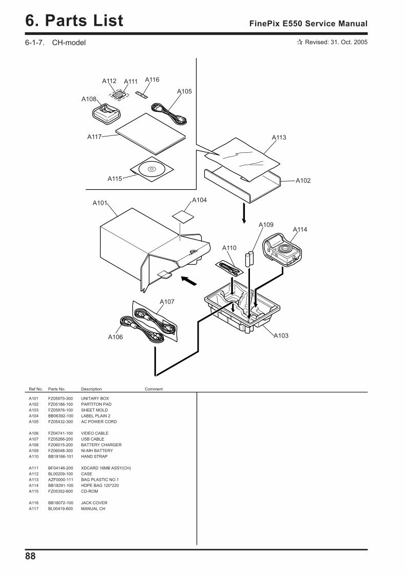
88
6. Parts List FinePix E550 Service Manual
Revised: 31. Oct. 20056-1-7. CH-model
A105
A117
A101
A102
A103
A104
A106
A107
A108
A109
A110
A111A112
A113
A114
A115
A116
Ref No. Parts No. Description Comment
A101 FZ05970-300 UNITARY BOXA102 FZ05186-100 PARTITON PADA103 FZ05976-100 SHEET MOLDA104 BB06392-100 LABEL PLAIN 2A105 FZ05432-300 AC POWER CORD
A106 FZ04741-100 VIDEO CABLEA107 FZ05266-200 USB CABLEA108 FZ06015-200 BATTERY CHARGERA109 FZ06048-300 NI-MH BATTERYA110 BB18166-101 HAND STRAP
A111 BF04146-200 XDCARD 16MB ASSY(CH)A112 BL00209-100 CASEA113 AZF0000-111 BAG PLASTIC NO.1A114 BB18291-100 HDPE BAG 120*220A115 FZ05352-600 CD-ROM
A116 BB18072-100 JACK COVERA117 BL00419-600 MANUAL CH
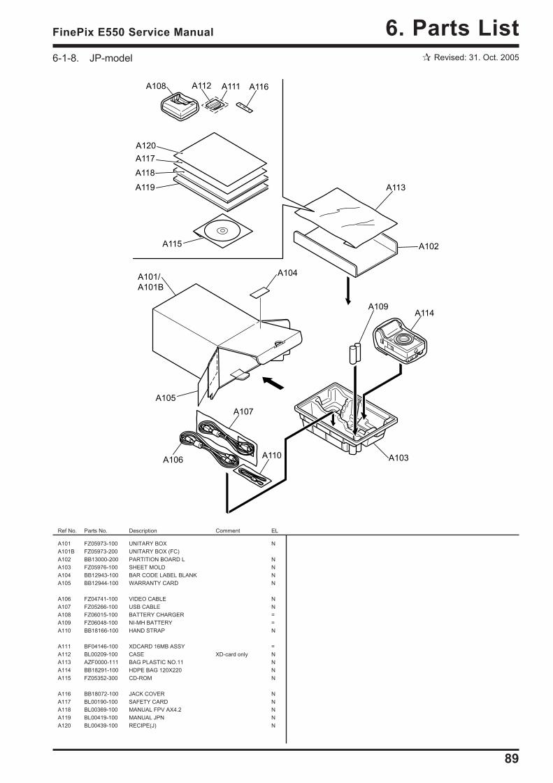
89
6. Parts ListFinePix E550 Service Manual
Revised: 31. Oct. 20056-1-8. JP-model
Ref No. Parts No. Description Comment EL
A118
A119
A101/
A101B
A102
A103
A104
A105
A106
A107
A108
A109
A110
A111A112
A113
A114
A115
A116
A117
A120
A101 FZ05973-100 UNITARY BOX NA101B FZ05973-200 UNITARY BOX (FC)A102 BB13000-200 PARTITION BOARD L NA103 FZ05976-100 SHEET MOLD NA104 BB12943-100 BAR CODE LABEL BLANK NA105 BB12944-100 WARRANTY CARD N
A106 FZ04741-100 VIDEO CABLE NA107 FZ05266-100 USB CABLE NA108 FZ06015-100 BATTERY CHARGER =A109 FZ06048-100 NI-MH BATTERY =A110 BB18166-100 HAND STRAP N
A111 BF04146-100 XDCARD 16MB ASSY =A112 BL00209-100 CASE XD-card only NA113 AZF0000-111 BAG PLASTIC NO.11 NA114 BB18291-100 HDPE BAG 120X220 NA115 FZ05352-300 CD-ROM N
A116 BB18072-100 JACK COVER NA117 BL00190-100 SAFETY CARD NA118 BL00369-100 MANUAL FPV AX4.2 NA119 BL00419-100 MANUAL JPN NA120 BL00439-100 RECIPE(J) N
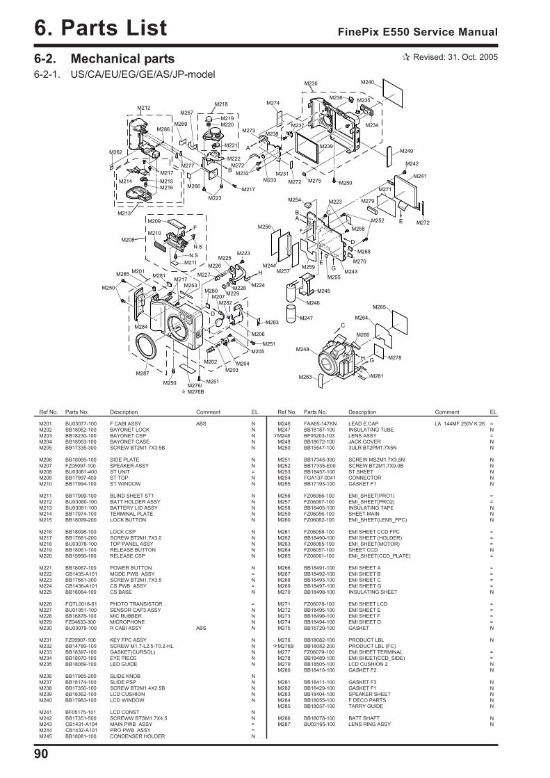
90
6. Parts List FinePix E550 Service Manual
M201 BU03077-100 F CABI ASSY ABS NM202 BB18062-100 BAYONET LOCK NM203 BB18230-100 BAYONET CSP NM204 BB18063-100 BAYONET CASE NM205 BB17335-300 SCREW BT2M1.7X3.5B N
M206 BB18065-100 SIDE PLATE NM207 FZ05997-100 SPEAKER ASSY NM208 BU03061-400 ST UNIT =M209 BB17997-400 ST TOP NM210 BB17994-100 ST WINDOW N
M211 BB17999-100 BLIND SHEET ST1 NM212 BU03080-100 BATT HOLDER ASSY NM213 BU03081-100 BATTERY LID ASSY NM214 BB17974-100 TERMINAL PLATE NM215 BB18099-200 LOCK BUTTON N
M216 BB18098-100 LOCK CSP NM217 BB17681-200 SCREW BT2M1.7X3.0 NM218 BU03078-100 TOP PANEL ASSY NM219 BB18061-100 RELEASE BUTTON NM220 BB15956-100 RELEASE CSP N
M221 BB18067-100 POWER BUTTON NM222 CB1435-A101 MODE PWB ASSY =M223 BB17681-300 SCREW BT2M1.7X3.5 NM224 CB1436-A101 CS PWB ASSY =M225 BB18064-100 CS BASE N
M226 FQTL0018-01 PHOTO TRANSISTOR =M227 BU01951-100 SENSOR CAP3 ASSY NM228 BB16878-100 MIC RUBBER NM229 FZ04833-300 MICROPHONE NM230 BU03079-100 R CABI ASSY ABS N
M231 FZ05907-100 KEY FPC ASSY NM232 BB14789-100 SCREW M1.7-L2.5-T0.2-HL NM233 BB18397-100 GASKET(CURSOL) NM234 BB18070-100 EYE PIECE NM235 BB18069-100 LED GUIDE N
M236 BB17965-200 SLIDE KNOB NM237 BB18174-100 SLIDE PSP NM238 BB17350-100 SCREW BT2M1.4X2.5B NM239 BB18362-100 LCD CUSHION NM240 BB17983-100 LCD WINDOW N
M241 BF05175-101 LCD CONST NM242 BB17351-500 SCREWW BTSM1.7X4.5 NM243 CB1431-A104 MAIN PWB ASSY =M244 CB1432-A101 PRO PWB ASSY =M245 BB18081-100 CONDENSER HOLDER N
Ref No. Parts No. Description Comment EL Ref No. Parts No. Description Comment EL
M246 FAA65-147KN LEAD E.CAP LA 144MF 250V K 26 =M247 BB18187-100 INSULATING TUBE NM248 BF05203-103 LENS ASSY =M249 BB18072-100 JACK COVER NM250 BB15547-100 3ULR BT2PM1.7X5N N
M251 BB17345-300 SCREW MS2M1.7X3.5N NM252 BB17335-E00 SCREW BT2M1.7X9.0B NM253 BB18457-100 ST SHEET NM254 FGA137-0041 CONNECTOR NM255 BB17193-100 GASKET F1 N
M256 FZ06066-100 EMI_SHEET(PRO1) =M257 FZ06067-100 EMI_SHEET(PRO2) =M258 BB18405-100 INSULATING TAPE NM259 FZ06056-100 SHEET MAIN NM260 FZ06062-100 EMI_SHEET(LENS_FPC) N
M261 FZ06058-100 EMI SHEET CCD FPC =M262 BB18490-100 EMI SHEET (HOLDER) =M263 FZ06065-100 EMI_SHEET(MOTOR) =M264 FZ06057-100 SHEET CCD NM265 FZ06061-100 EMI_SHEET(CCD_PLATE) =
M266 BB18491-100 EMI SHEET A =M267 BB18492-100 EMI SHEET B =M268 BB18493-100 EMI SHEET C =M269 BB18497-100 EMI SHEET G =M270 BB18498-100 INSULATING SHEET N
M271 FZ06078-100 EMI SHEET LCD =M272 BB18495-100 EMI SHEET E =M273 BB18496-100 EMI SHEET F =M274 BB18494-100 EMI SHEET D =M275 BB16729-100 GASKET N
M276 BB18082-100 PRODUCT LBL NM276B BB18082-200 PRODUCT LBL (FC)M277 FZ06079-100 EMI SHEET TERMINAL =M278 BB18489-100 EMI SHEET(CCD_SIDE) =M279 BB18505-100 LCD CUSHION 2 NM280 BB18410-100 GASKET F2 N
M281 BB18411-100 GASKET F3 NM282 BB18429-100 GASKET F1 NM283 BB18404-100 SPEAKER SHEET NM284 BB18055-100 F DECO PARTS NM285 BB18057-100 TARRY GUIDE N
M286 BB18078-100 BATT SHAFT NM287 BU03165-100 LENS RING ASSY N
C
B
E
B
A
D
D
F
G
C
F
H
H
E
G
A
M201
M202
M203
M204
M205
M206
M251
M208
M209
M210
M211
N.S
N.S
M212
M213
M214 M215
M216
M217
M286
M218
M219
M220
M221
M222
M223
M217
M267
M269
M266
M277
M274
M273
M272
M232
M233 M272 M275M250
M230 M240
M249
M234
M236M235
M239
M238
M237
M242
M241
M272
M271
M279
M287
M284
M285
M258
M252
M223M254
M243
M270
M268
M245
M247
M246
M259M244
M256
M257
M224
M223M225
M226
M227
M228
M229M207
M251
M250
M250
M278
M265
M264
M260
M248
M263 M261
M282
M280
M281
M253
M217
M283
M262
M231
M255
M276/
M276B
6-2. Mechanical parts6-2-1. US/CA/EU/EG/GE/AS/JP-model
Revised: 31. Oct. 2005
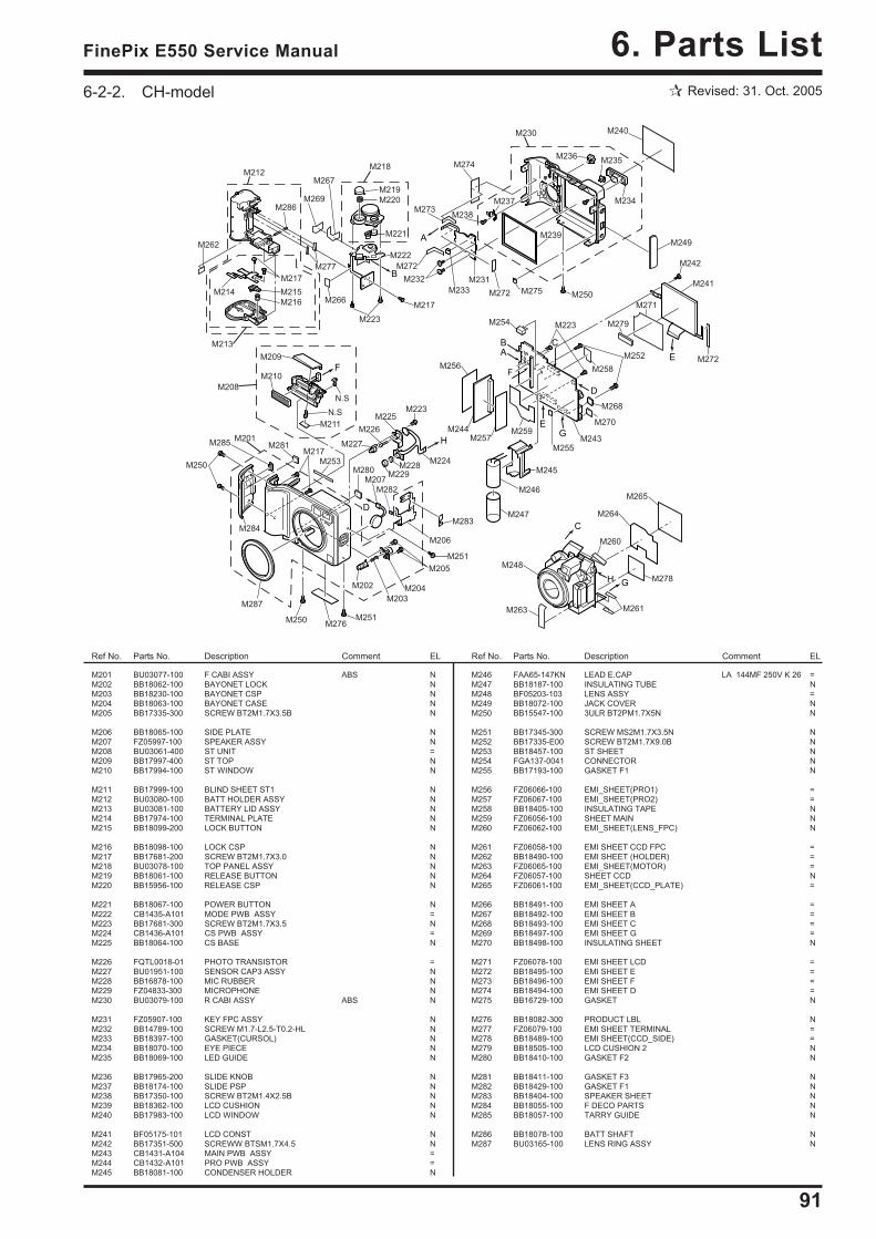
91
6. Parts ListFinePix E550 Service Manual
6-2-2. CH-model
M201 BU03077-100 F CABI ASSY ABS NM202 BB18062-100 BAYONET LOCK NM203 BB18230-100 BAYONET CSP NM204 BB18063-100 BAYONET CASE NM205 BB17335-300 SCREW BT2M1.7X3.5B N
M206 BB18065-100 SIDE PLATE NM207 FZ05997-100 SPEAKER ASSY NM208 BU03061-400 ST UNIT =M209 BB17997-400 ST TOP NM210 BB17994-100 ST WINDOW N
M211 BB17999-100 BLIND SHEET ST1 NM212 BU03080-100 BATT HOLDER ASSY NM213 BU03081-100 BATTERY LID ASSY NM214 BB17974-100 TERMINAL PLATE NM215 BB18099-200 LOCK BUTTON N
M216 BB18098-100 LOCK CSP NM217 BB17681-200 SCREW BT2M1.7X3.0 NM218 BU03078-100 TOP PANEL ASSY NM219 BB18061-100 RELEASE BUTTON NM220 BB15956-100 RELEASE CSP N
M221 BB18067-100 POWER BUTTON NM222 CB1435-A101 MODE PWB ASSY =M223 BB17681-300 SCREW BT2M1.7X3.5 NM224 CB1436-A101 CS PWB ASSY =M225 BB18064-100 CS BASE N
M226 FQTL0018-01 PHOTO TRANSISTOR =M227 BU01951-100 SENSOR CAP3 ASSY NM228 BB16878-100 MIC RUBBER NM229 FZ04833-300 MICROPHONE NM230 BU03079-100 R CABI ASSY ABS N
M231 FZ05907-100 KEY FPC ASSY NM232 BB14789-100 SCREW M1.7-L2.5-T0.2-HL NM233 BB18397-100 GASKET(CURSOL) NM234 BB18070-100 EYE PIECE NM235 BB18069-100 LED GUIDE N
M236 BB17965-200 SLIDE KNOB NM237 BB18174-100 SLIDE PSP NM238 BB17350-100 SCREW BT2M1.4X2.5B NM239 BB18362-100 LCD CUSHION NM240 BB17983-100 LCD WINDOW N
M241 BF05175-101 LCD CONST NM242 BB17351-500 SCREWW BTSM1.7X4.5 NM243 CB1431-A104 MAIN PWB ASSY =M244 CB1432-A101 PRO PWB ASSY =M245 BB18081-100 CONDENSER HOLDER N
Ref No. Parts No. Description Comment EL Ref No. Parts No. Description Comment EL
M246 FAA65-147KN LEAD E.CAP LA 144MF 250V K 26 =M247 BB18187-100 INSULATING TUBE NM248 BF05203-103 LENS ASSY =M249 BB18072-100 JACK COVER NM250 BB15547-100 3ULR BT2PM1.7X5N N
M251 BB17345-300 SCREW MS2M1.7X3.5N NM252 BB17335-E00 SCREW BT2M1.7X9.0B NM253 BB18457-100 ST SHEET NM254 FGA137-0041 CONNECTOR NM255 BB17193-100 GASKET F1 N
M256 FZ06066-100 EMI_SHEET(PRO1) =M257 FZ06067-100 EMI_SHEET(PRO2) =M258 BB18405-100 INSULATING TAPE NM259 FZ06056-100 SHEET MAIN NM260 FZ06062-100 EMI_SHEET(LENS_FPC) N
M261 FZ06058-100 EMI SHEET CCD FPC =M262 BB18490-100 EMI SHEET (HOLDER) =M263 FZ06065-100 EMI_SHEET(MOTOR) =M264 FZ06057-100 SHEET CCD NM265 FZ06061-100 EMI_SHEET(CCD_PLATE) =
M266 BB18491-100 EMI SHEET A =M267 BB18492-100 EMI SHEET B =M268 BB18493-100 EMI SHEET C =M269 BB18497-100 EMI SHEET G =M270 BB18498-100 INSULATING SHEET N
M271 FZ06078-100 EMI SHEET LCD =M272 BB18495-100 EMI SHEET E =M273 BB18496-100 EMI SHEET F =M274 BB18494-100 EMI SHEET D =M275 BB16729-100 GASKET N
M276 BB18082-300 PRODUCT LBL NM277 FZ06079-100 EMI SHEET TERMINAL =M278 BB18489-100 EMI SHEET(CCD_SIDE) =M279 BB18505-100 LCD CUSHION 2 NM280 BB18410-100 GASKET F2 N
M281 BB18411-100 GASKET F3 NM282 BB18429-100 GASKET F1 NM283 BB18404-100 SPEAKER SHEET NM284 BB18055-100 F DECO PARTS NM285 BB18057-100 TARRY GUIDE N
M286 BB18078-100 BATT SHAFT NM287 BU03165-100 LENS RING ASSY N
C
B
E
B
A
D
D
F
G
C
F
H
H
E
G
A
M201
M202
M203
M204
M205
M206
M251
M208
M209
M210
M211
N.S
N.S
M212
M213
M214 M215
M216
M217
M286
M218
M219
M220
M221
M222
M223
M217
M267
M269
M266
M277
M274
M273
M272
M232
M233 M272 M275M250
M230 M240
M249
M234
M236M235
M239
M238
M237
M242
M241
M272
M271
M279
M287
M284
M285
M258
M252
M223M254
M243
M270
M268
M245
M247
M246
M259M244
M256
M257
M224
M223M225
M226
M227
M228
M229M207
M251
M250
M250
M278
M265
M264
M260
M248
M263 M261
M282
M280
M281
M253
M217
M283
M262
M231
M276
M255
Revised: 31. Oct. 2005
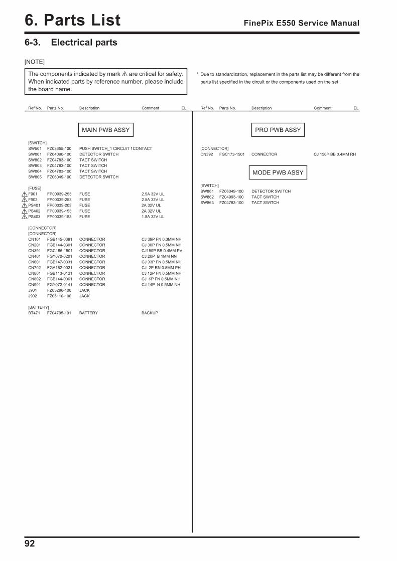
92
6. Parts List FinePix E550 Service Manual
6-3. Electrical parts
[NOTE]
The components indicated by mark are critical for safety.When indicated parts by reference number, please includethe board name.
Ref No. Parts No. Description Comment EL Ref No. Parts No. Description Comment EL
* Due to standardization, replacement in the parts list may be different from theparts list specified in the circuit or the components used on the set.
MAIN PWB ASSY
[SWITCH]SW501 FZ03655-100 PUSH SWITCH_1 CIRCUIT 1CONTACTSW801 FZ04090-100 DETECTOR SWITCHSW802 FZ04783-100 TACT SWITCHSW803 FZ04783-100 TACT SWITCHSW804 FZ04783-100 TACT SWITCHSW805 FZ06049-100 DETECTOR SWITCH
[FUSE]F901 FP00039-253 FUSE 2.5A 32V ULF902 FP00039-253 FUSE 2.5A 32V ULPS401 FP00039-203 FUSE 2A 32V ULPS402 FP00039-153 FUSE 2A 32V ULPS403 FP00039-153 FUSE 1.5A 32V UL
[CONNECTOR][CONNECTOR]CN101 FGB145-0391 CONNECTOR CJ 39P FN 0.3MM NHCN201 FGB144-0301 CONNECTOR CJ 30P FN 0.5MM NHCN391 FGC186-1501 CONNECTOR CJ150P BB 0.4MM PVCN401 FGY070-0201 CONNECTOR CJ 20P B 1MM NNCN601 FGB147-0331 CONNECTOR CJ 33P FN 0.5MM NHCN702 FGA162-0021 CONNECTOR CJ 2P RN 0.8MM PHCN801 FGB113-0121 CONNECTOR CJ 12P FN 0.5MM NHCN802 FGB144-0061 CONNECTOR CJ 6P FN 0.5MM NHCN901 FGY072-0141 CONNECTOR CJ 14P N 0.5MM NHJ901 FZ05286-100 JACKJ902 FZ05110-100 JACK
[BATTERY]BT471 FZ04705-101 BATTERY BACKUP
PRO PWB ASSY
[CONNECTOR]CN392 FGC173-1501 CONNECTOR CJ 150P BB 0.4MM RH
MODE PWB ASSY
[SWITCH]SW861 FZ06049-100 DETECTOR SWITCHSW862 FZ04993-100 TACT SWITCHSW863 FZ04783-100 TACT SWITCH
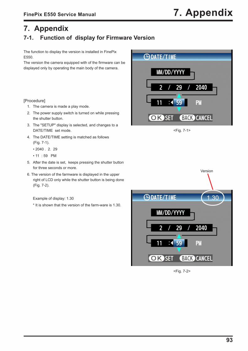
93
7. AppendixFinePix E550 Service Manual
7. Appendix7-1. Function of display for Firmware Version
The function to display the version is installed in FinePixE550.The version the camera equipped with of the firmware can bedisplayed only by operating the main body of the camera.
[Procedure]1. The camera is made a play mode.
2. The power supply switch is turned on while pressingthe shutter button.
3. The "SETUP" display is selected, and changes to aDATE/TIME set mode.
4. The DATE/TIME setting is matched as follows(Fig. 7-1).
• 2040 . 2. 29
• 11 : 59 PM
5. After the date is set, keeps pressing the shutter buttonfor three seconds or more.
6. The version of the farmware is displayed in the upperright of LCD only while the shutter button is being done(Fig. 7-2).
Example of display: 1.30
* It is shown that the version of the farm-ware is 1.30.
<Fig. 7-1>
<Fig. 7-2>
Version
1.30
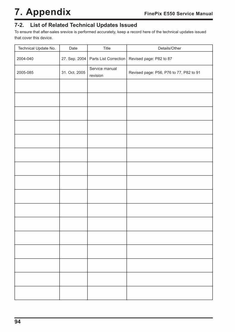
94
7. Appendix FinePix E550 Service Manual
7-2. List of Related Technical Updates IssuedTo ensure that after-sales srevice is performed accuratety, keep a record here of the technical updates issuedthat cover this device.
Technical Update No. Date Title Details/Other
2004-040 27. Sep. 2004 Parts List Correction Revised page: P82 to 87
2005-085 31. Oct. 2005Service manual
Revised page: P56, P76 to 77, P82 to 91revision

26-30, Nishiazabu 2-chome, Minato-ku, Tokyo 106-8620, Japan.
FUJI PHOTO FILM CO., LTD.