Embed Size (px)
Citation preview

Fuji IGBT Module V Series 1700V Family
Technical Notes
1 RBSOA, SCSOA ・・・・・・・・・・・・・・・・・ MT5F24382
2 High current output characteristics ・・・・・・・・・・・・・・・・・ MT5F24040
3 Switching energy and Reverse recovery
dV/dt with combination of Rg and Cge ・・・・・・・・・・・・・・・・・ MT5F27844
4 Junction breakdown voltage VCES and
junction temperature Tj ・・・・・・・・・・・・・・・・・ MT5F27807
5 -Vge and switching loss characteristics ・・・・・・・・・・・・・・・・・ MT5F27813
6 Gate resistance dependence of surge
voltage ・・・・・・・・・・・・・・・・・ MT5F27829
7 -dlc/dt at turn-off and Tj characteristics ・・・・・・・・・・・・・・・・・ MT5F27831
8 Parallel connection of 2in1 package modules ・・・・・・・・・・・・・・・・・ MT5F27805
9 Short-circuit capacity ・・・・・・・・・・・・・・・・・ MT5F27809

1Jan.2014
Technical data: MT5F24382

1Jan.2014
Technical data: MT5F24040

1Jan.2014
Technical data: MT5F27844
− Fuji IGBT Module V Series 1700V Family −
Switching energy and Reverse recovery dV/dt with combination of Rg and Cge
Type name:2MBI550VN-170-50
Conditions:Vdc=900V, Ic, If=550A, Vge=+/-15V, Rg=vari., Cge=0, 47, 100nF
Tj=25℃ or 125℃
(a) Rg dependence of reverse recovery dv/dt (b) Rg dependence of turn-on loss
(c) Rg dependence of turn-off loss (d) Rg dependence of reverse recovery loss

2Jan.2014
Technical data: MT5F27844
0
200
400
600
800
1000
1200
0 5 10 15 20
Eon+
Eoff+
Err (
mJ/
puls
e)
dv/dt at reverse recovery (kV/usec)
0nF
47nF
100nF
Rg=15Ω
Rg=1.8Ω
Rg=3.3Ω
Rg=6.8Ω
Additional external capacitance between IGBT gate and emitter terminals has an effect of improving the
trade off between reverse recovery dv/dt and total switching energy as shown in above chart. However,
simply add Cge slows down the IGBT significantly and it results penalty of increasing the switching loss.
Therefore, the combination of extra-Cge and reduction of the gate resistance (Rg) is recommended to
achieve the highest performance of lower dV/dt as well as keep switching energy low. Typical Cge and Rg
values for initial guess are : 2x of Cies in our datasheet and 1/2 Rg of your original design, however,
experimental confirmation in practical application is recommended.
0V0A
IF
VR
dv/dt
0V0A
IF
VR
dv/dt

1Jan.2014
Technical data: MT5F27807
− Fuji IGBT Module V Series 1700V Family −
Junction breakdown voltage VCES and junction temperature Tj
In general, the breakdown voltage of power semiconductor devices have liner function to the junction
temperature if "Impact ionization" and "Avalanche multiplication" are dominant physics of junction
breakdown At low temperature, the carriers in drift region are relatively easier to have high velocity because
of less scattering due to lattice vibration so that the impact ionization ratio increases. Therefore, the
breakdown voltage of the power semiconductor device becomes lower at low temperature. The
temperature effect shown in the above figure should be taken into account into practical design not to
exceed breakdown voltage if the target applications have chances of low temperature operation and/or
start-up.
-50 -25 0 25 501000
1200
1400
1600
1800
2000
2200
2400
1700V V series
Typ.
Min.
Junction Temperature Tj (oC)
Bre
ak d
own
volta
ge V
CE
S (
V)
Fig. Junction Temperature Dependence of Junction Breakdown Voltage
1Jan.2014
Technical data: MT5F27813
− Fuji IGBT Module V Series 1700V Family −
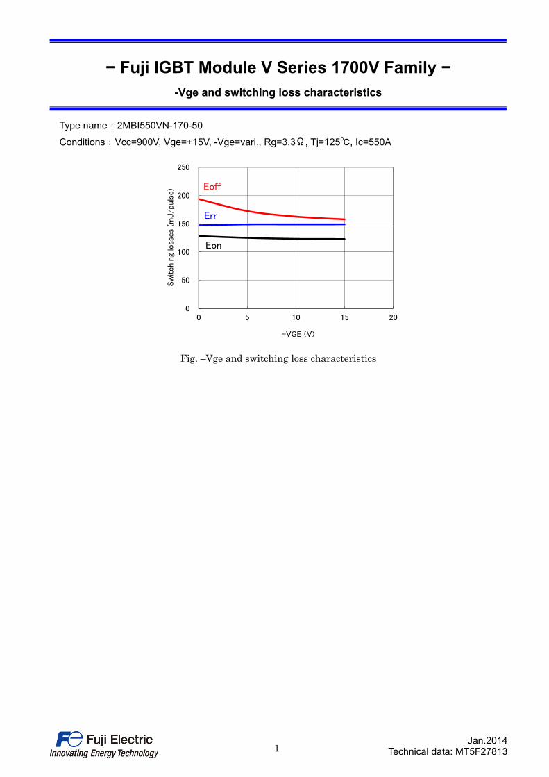
-Vge and switching loss characteristics
Type name:2MBI550VN-170-50
Conditions:Vcc=900V, Vge=+15V, -Vge=vari., Rg=3.3Ω, Tj=125℃, Ic=550A
0
50
100
150
200
250
0 5 10 15 20
Sw
itchin
g lo
sses
(mJ/pu
lse)
-VGE (V)
Eon
Err
Eoff
Fig. –Vge and switching loss characteristics
1Jan.2014
Technical data: MT5F27829
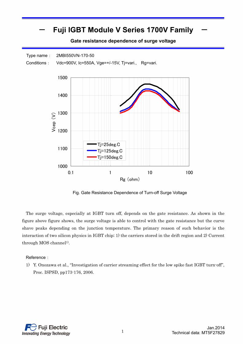
- Fuji IGBT Module V Series 1700V Family - Gate resistance dependence of surge voltage
Type name: 2MBI550VN-170-50
Conditions: Vdc=900V, Ic=550A, Vge=+/-15V, Tj=vari., Rg=vari.
The surge voltage, especially at IGBT turn off, depends on the gate resistance. As shown in the
figure above figure shows, the surge voltage is able to control with the gate resistance but the curve
shave peaks depending on the junction temperature. The primary reason of such behavior is the
interaction of two silicon physics in IGBT chip; 1) the carriers stored in the drift region and 2) Current
through MOS channel1).
Reference:
1) Y. Onozawa et al., “Investigation of carrier streaming effect for the low spike fast IGBT turn-off”,
Proc. ISPSD, pp173-176, 2006.
1000
1100
1200
1300
1400
1500
0.1 1 10 100
Rg (ohm)
Vcep
(V
)
Tj=25deg.C
Tj=125deg.C
Tj=150deg.C
Fig. Gate Resistance Dependence of Turn-off Surge Voltage
1Jan.2014
Technical data: MT5F27831
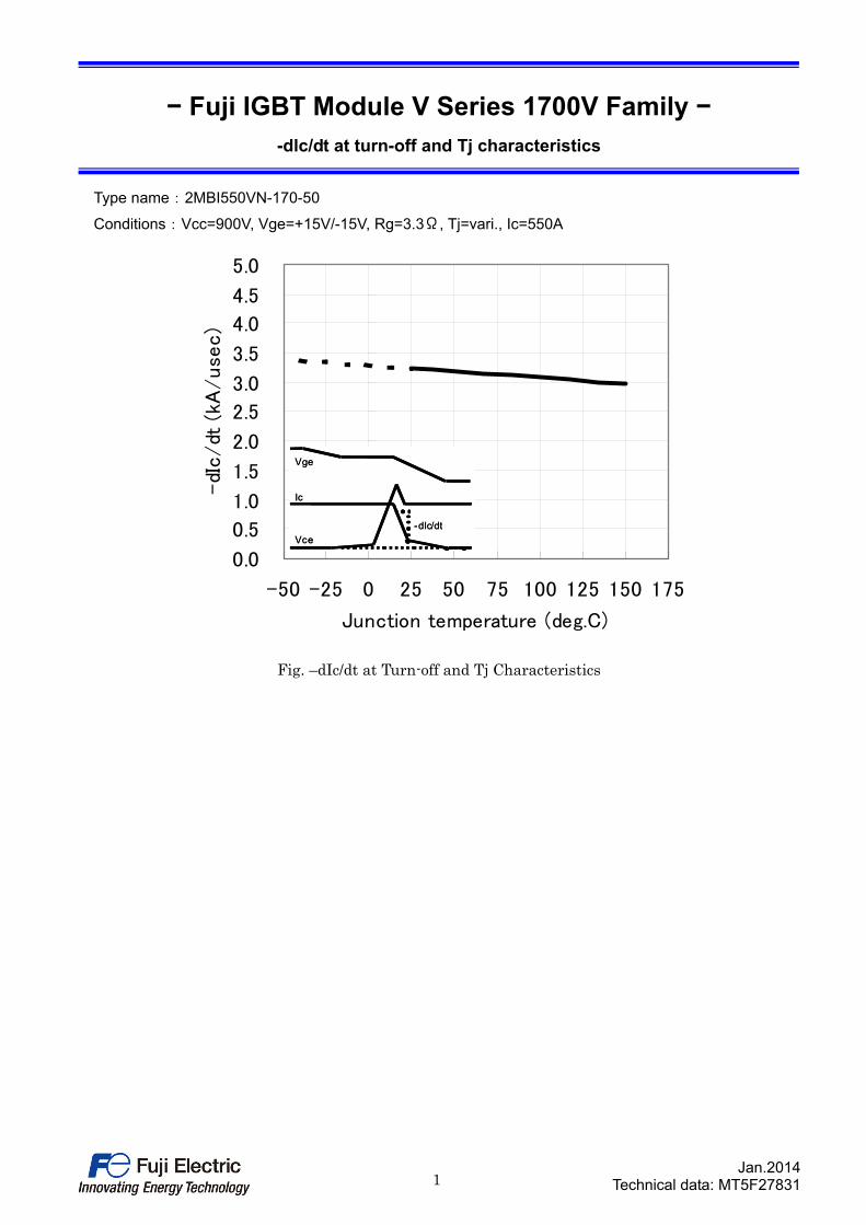
− Fuji IGBT Module V Series 1700V Family −
-dlc/dt at turn-off and Tj characteristics
Type name:2MBI550VN-170-50
Conditions:Vcc=900V, Vge=+15V/-15V, Rg=3.3Ω, Tj=vari., Ic=550A
0.0
0.5
1.0
1.5
2.0
2.5
3.0
3.5
4.0
4.5
5.0
-50 -25 0 25 50 75 100 125 150 175
Junction temperature (deg.C)
-dI
c/dt
(kA
/use
c)
Vge
Ic
Vce
-dIc/dt
Vge
Ic
Vce
-dIc/dt
Fig. –dIc/dt at Turn-off and Tj Characteristics
1Jan.2014
Technical data: MT5F27805
− Fuji IGBT Module V Series 1700V Family −
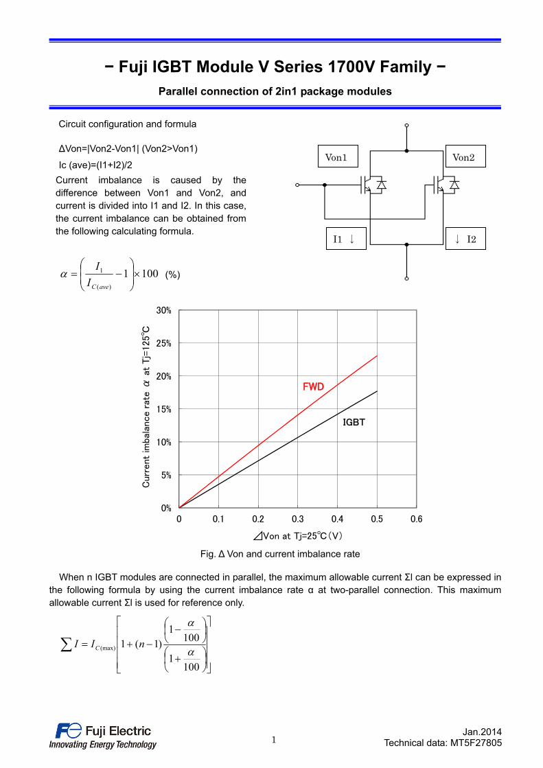
Parallel connection of 2in1 package modules
Circuit configuration and formula
∆Von=|Von2-Von1| (Von2>Von1)
Ic (ave)=(I1+I2)/2
Current imbalance is caused by the difference between Von1 and Von2, and current is divided into I1 and I2. In this case, the current imbalance can be obtained from the following calculating formula.
1001)(
1
aveCI
I (%)
0%
5%
10%
15%
20%
25%
30%
0 0.1 0.2 0.3 0.4 0.5 0.6
Curr
ent
imba
lance r
ate α
at
Tj=
125℃
⊿Von at Tj=25℃(V)
FWD
IGBT
Fig. ∆ Von and current imbalance rate
When n IGBT modules are connected in parallel, the maximum allowable current Σl can be expressed in the following formula by using the current imbalance rate α at two-parallel connection. This maximum allowable current Σl is used for reference only.
1001
1001
)1(1(max)
nII C
Von1
I1 ↓ ↓ I2
Von2
1Jan.2014
Technical data: MT5F27809
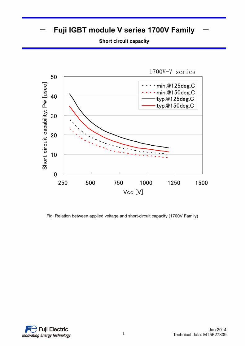
- Fuji IGBT module V series 1700V Family - Short circuit capacity
0
10
20
30
40
50
250 500 750 1000 1250 1500
Vcc [V]
Short
circuit c
apab
ility
: P
w [
use
c]
[email protected][email protected][email protected][email protected]
Fig. Relation between applied voltage and short-circuit capacity (1700V Family)
1700V-V series

WARNING
1.��This�Catalog�contains�the�product�specifications,�characteristics,�data,�materials,�and�structures�as�of�January 2014.The
��contents�are�subject�to�change�without�notice�for�specification�changes�or�other�reasons.��When�using�a�product�listed�in�this�Catalog,�be�
sur�to�obtain�the�latest�specifications.
2.��All�applications�described�in�this�Catalog�exemplify�the�use�of�Fuji's�products�for�your�reference�only.��No�right�or�license,�either�express�or�implied,�under�any�patent,�copyright,�trade�secret�or�other�intellectual�property�right�owned�by�Fuji�Electric�Co.,�Ltd.�is�(or�shall�be�deemed)�granted.��Fuji�Electric�Co.,�Ltd.�makes�no�representation�or�warranty,�whether�express�or�implied,�relating�to�the�infringement�or�alleged�infringement�of�other's�intellectual�property�rights�which�may�arise�from�the�use�of�the�applications�described�herein.
3.��Although�Fuji�Electric�Co.,�Ltd.�is�enhancing�product�quality�and�reliability,�a�small�percentage�of�semiconductor�products�may�become�faulty.��When�using�Fuji�Electric�semiconductor�products�in�your�equipment,�you�are�requested�to�take�adequate�safety�measures�to�prevent�the�equipment�from�causing�a�physical�injury,�fire,�or�other�problem�if�any�of�the�products�become�faulty.��It�is�recommended�to�make�your�design�failsafe,�flame�retardant,�and�free�of�malfunction.
�4.��The�products�introduced�in�this�Catalog�are�intended�for�use�in�the�following�electronic�and�electrical�equipment�which�has�normal�reliability�requirements.�•�Computers� •�OA�equipment� •�Communications�equipment�(terminal�devices)� •�Measurement�equipment�•�Machine�tools� •�Audiovisual�equipment� •�Electrical�home�appliances� •�Personal�equipment� •�Industrial�robots�etc.
5.��If�you�need�to�use�a�product�in�this�Catalog�for�equipment�requiring�higher�reliability�than�normal,�such�as�for�the�equipment�listed�below,�it�is�imperative�to�contact�Fuji�Electric�Co.,�Ltd.�to�obtain�prior�approval.��When�using�these�products�for�such�equipment,�take�adequate�measures�such�as�a�backup�system�to�prevent�the�equipment�from�malfunctioning�even�if�a�Fuji's�product�incorporated�in�the�equipment�becomes�faulty.�•�Transportation�equipment�(mounted�on�cars�and�ships)� � •�Trunk�communications�equipment�•�Traffic-signal�control�equipment� � � •�Gas�leakage�detectors�with�an�auto-shut-off�feature�•�Emergency�equipment�for�responding�to�disasters�and�anti-burglary�devices� •�Safety�devices�•�Medical�equipment
6.��Do�not�use�products�in�this�Catalog�for�the�equipment�requiring�strict�reliability�such�as�the�following�and�equivalents�to�strategic�equipment�(without�limitation).�•�Space�equipment� � •�Aeronautic�equipment� •�Nuclear�control�equipment�•�Submarine�repeater�equipment
7.��Copyright�©1996-2014�by�Fuji�Electric�Co.,�Ltd.�All�rights�reserved.�No�part�of�this�Catalog�may�be�reproduced�in�any�form�or�by�any�means�without�the�express�permission�of�Fuji�Electric�Co.,�Ltd.
8.��If�you�have�any�question�about�any�portion�in�this�Catalog,�ask�Fuji�Electric�Co.,�Ltd.�or�its�sales�agents�before�using�the�product.�Neither�Fuji�Electric�Co.,�Ltd.�nor�its�agents�shall�be�liable�for�any�injury�caused�by�any�use�of�the�products�not�in�accordance�with�instructions�set�forth�herein.