Embed Size (px)
Citation preview

Instruction Manual
PORTABLE TYPE ULTRASONIC FLOWMETER
TYPE: FLOW TRANSMITTER FSC-4DETECTOR FSS-1, FSD-1
INF-TN4FSC-E
INF-TN4FSC-E i
PREFACE
Product nationality : Japan
-
Notice
Option

ii INF-TN4FSC-E
CONTENTS
34
5
88
333435
3738
INF-TN4FSC-E iii
44454548
535354
575758
7375
8385
iv INF-TN4FSC-E
INF-TN4FSC-E v
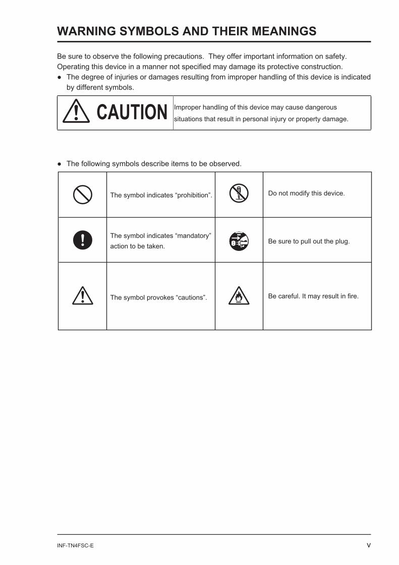
Be sure to observe the following precautions. They offer important information on safety.
by different symbols.
CAUTION Improper handling of this device may cause dangerous
The symbol indicates “prohibition”.
The symbol provokes “cautions”.
The symbol indicates “mandatory”action to be taken.
Do not modify this device.
Be careful. It may result in fire.
Be sure to pull out the plug.
WARNING SYMBOLS AND THEIR MEANINGS
vi INF-TN4FSC-E
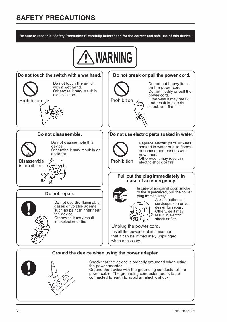
Be sure to read this “Safety Precautions” carefully beforehand for the correct and safe use of this device.
Do not touch the switch with a wet hand. Do not break or pull the power cord.
Do not put heavy items on the power cord. Do not modify or pull the power cord.Otherwise it may break and result in electric shock and fire.
Do not disassemble.Do not disassemble this device.Otherwise it may result in anaccident.
Do not use electric parts soaked in water.
Replace electric parts or wires soaked in water due to floods or some other reasons with new ones. Otherwise it may result in electric shock or fire.
Do not repair.
Do not use the flammable gases or volatile agents such as paint thinner near the device. Otherwise it may result in explosion or fire.
Pull out the plug immediately in case of an emergency.
In case of abnormal odor, smoke or fire is perceived, pull the power plug immediately.
Ask an authorized serviceperson or yourdealer for repair.Otherwise it may result in electricshock or fire.
Do not touch the switch with a wet hand. Otherwise it may result in electric shock.
WARNING
Prohibition
Prohibition
Prohibition
Disassembleis prohibited.
Unplug the power cord.Install the power cord in a manner that it can be immediately unplugged when necessary.
Ground the device when using the power adapter.
Check that the device is properly grounded when using the power adapter.Ground the device with the grounding conductor of the power cable. The grounding conductor needs to be connected to earth to avoid an electric shock.
SAFETY PRECAUTIONS
INF-TN4FSC-E vii
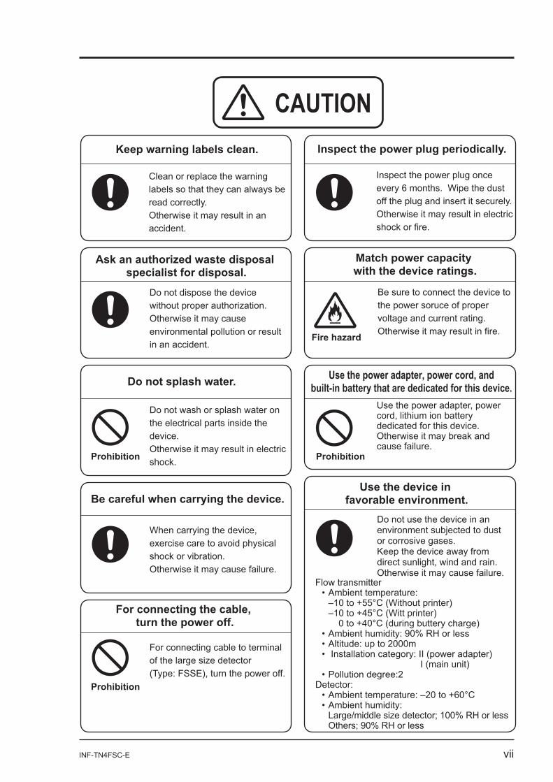
CAUTIONKeep warning labels clean.
Ask an authorized waste disposal specialist for disposal.
Do not splash water.
Prohibition
Prohibition
Be careful when carrying the device.
Inspect the power plug periodically.
Clean or replace the warning labels so that they can always be read correctly.Otherwise it may result in an accident.
Do not dispose the device without proper authorization.Otherwise it may cause environmental pollution or result in an accident.
Do not wash or splash water on the electrical parts inside the device.Otherwise it may result in electric shock.
When carrying the device, exercise care to avoid physical shock or vibration.Otherwise it may cause failure.
For connecting the cable, turn the power off.
For connecting cable to terminal of the large size detector (Type: FSSE), turn the power off.
Inspect the power plug once every 6 months. Wipe the dust off the plug and insert it securely.Otherwise it may result in electric shock or fire.
Match power capacity with the device ratings.
Fire hazard
Be sure to connect the device to the power soruce of proper voltage and current rating.Otherwise it may result in fire.
Use the power adapter, power cord, and built-in battery that are dedicated for this device.
Prohibition
Use the power adapter, power cord, lithium ion battery dedicated for this device.Otherwise it may break and cause failure.
Use the device in favorable environment.
Do not use the device in an environment subjected to dust or corrosive gases.Keep the device away from direct sunlight, wind and rain.Otherwise it may cause failure.
Flow transmitter
–10 to +55°C (Without printer) –10 to +45°C (Witt printer)
0 to +40°C (during buttery charge)RH or less
I (main unit)
Detector:
RH or less
viii INF-TN4FSC-E
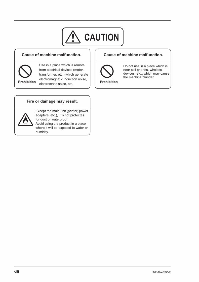
CAUTIONCause of machine malfunction. Cause of machine malfunction.
Prohibition Prohibition
Use in a place which is remote from electrical devices (motor, transformer, etc.) which generate electromagnetic induction noise, electrostatic noise, etc.
Fire or damage may result.
Do not use in a place which is near cell phones, wireless devices, etc., which may cause the machine blunder.
Except the main unit (printer, power adapters, etc.), it is not protectes for dust or waterproof.Avoid using the product in a place where it will be exposed to water or humidity.

INF-TN4FSC-E 1
1. OVERVIEW
-
2 INF-TN4FSC-E
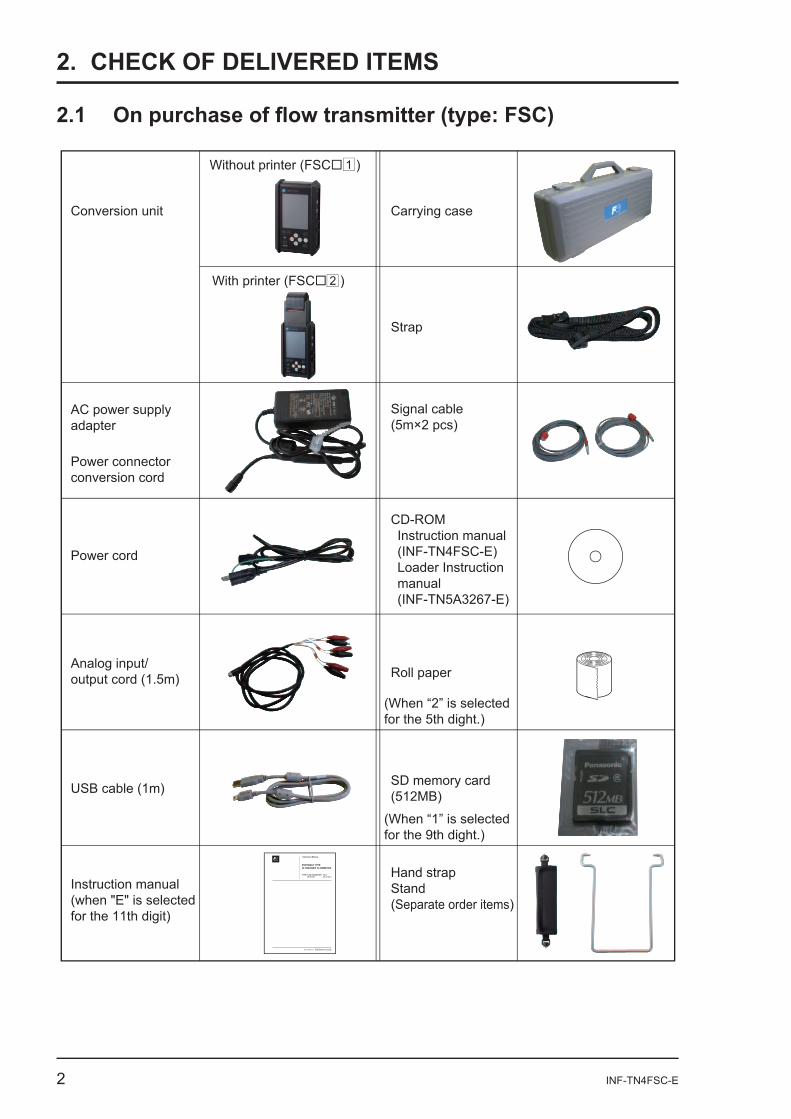
2. CHECK OF DELIVERED ITEMS
Conversion unit Carrying case
Strap
AC power supply adapter
Power connector conversion cord
Power cord
Analog input/output cord (1.5m)
USB cable (1m)
CD-ROMInstruction manual(INF-TN4FSC-E)Loader Instructionmanual(INF-TN5A3267-E)
Roll paper
(When “2” is selected for the 5th dight.)
(When “1” is selected for the 9th dight.)
SD memory card(512MB)
Hand strapStand(Separate order items)
Signal cable (5m×2 pcs)
Without printer (FSC )
Instruction manual(when "E" is selected for the 11th digit)
With printer (FSC )
1
2
Instruction Manual
PORTABLE TYPE ULTRASONIC FLOWMETER
TYPE: FLOW TRANSMITTER FSC-4DETECTOR FSS-1, FSD-1
INF-TN4FSC-E
INF-TN4FSC-E 3
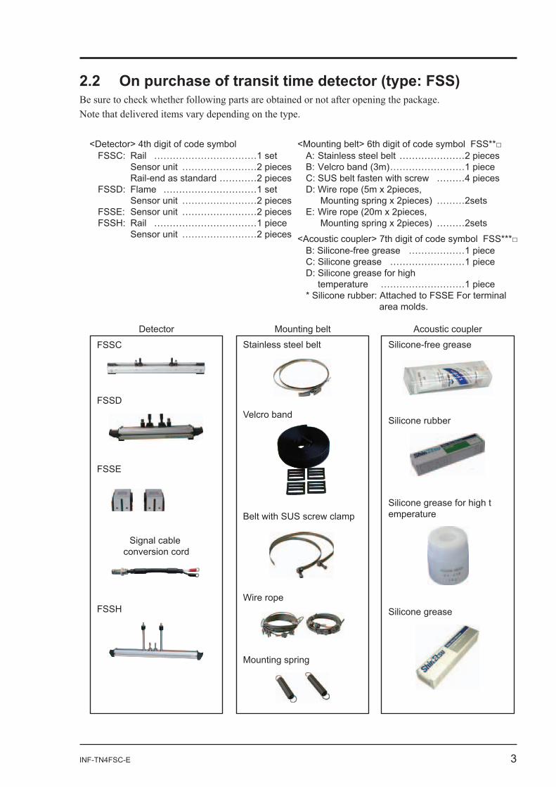
Detector Mounting belt Acoustic coupler
FSSD
FSSE
FSSH
Signal cable conversion cord
FSSC Stainless steel belt
Velcro band
Belt with SUS screw clamp
Wire rope
Mounting spring
Silicone-free grease
Silicone rubber
Silicone grease for high temperature
Silicone grease
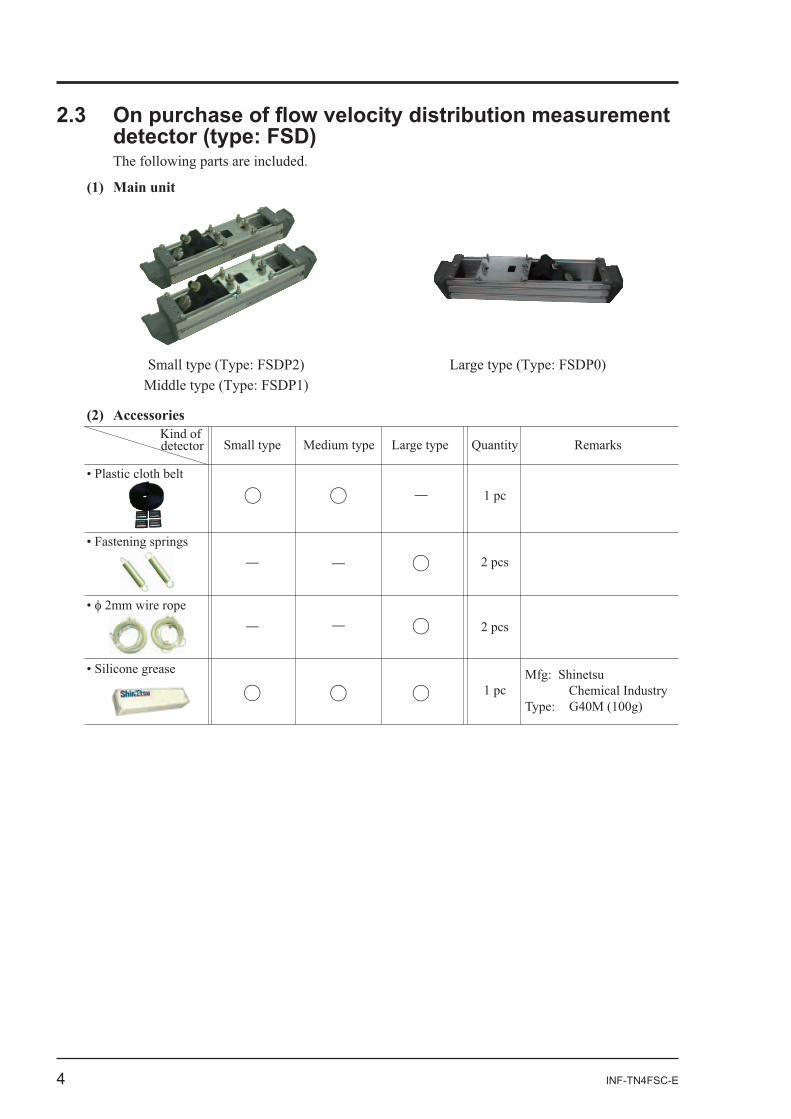
<Detector> 4th digit of code symbolFSSC: Rail ……………………………1 set Sensor unit ……………………2 pieces Rail-end as standard …………2 piecesFSSD: Flame …………………………1 set Sensor unit ……………………2 piecesFSSE: Sensor unit ……………………2 piecesFSSH: Rail ……………………………1 piece Sensor unit ……………………2 pieces
A: Stainless steel belt …………………2 piecesB: Velcro band (3m)……………………1 pieceC: SUS belt fasten with screw ………4 piecesD: Wire rope (5m x 2pieces, Mounting spring x 2pieces) ………2setsE: Wire rope (20m x 2pieces, Mounting spring x 2pieces) ………2sets
B: Silicone-free grease ………………1 pieceC: Silicone grease ……………………1 pieceD: Silicone grease for high temperature ………………………1 piece* Silicone rubber: Attached to FSSE For terminal area molds.
4 INF-TN4FSC-E
(1) Main unit
(2) Accessories
INF-TN4FSC-E 5
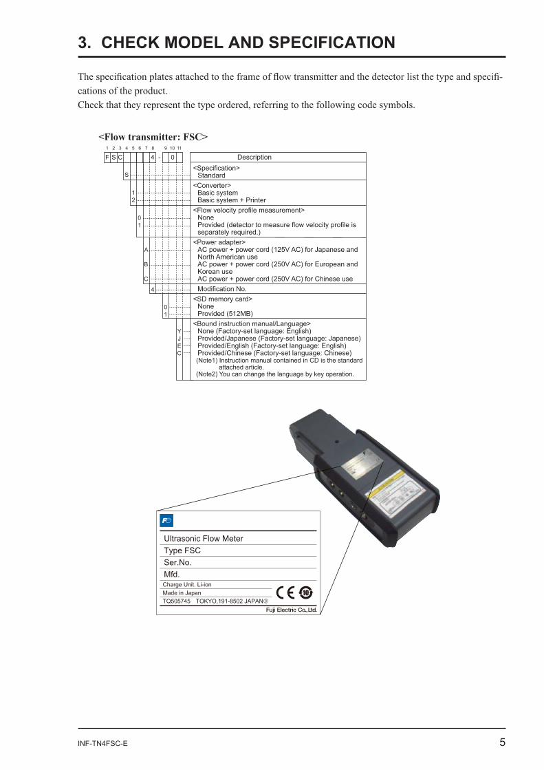
3. CHECK MODEL AND SPECIFICATION
-
<Flow transmitter: FSC>
4 0F S C Description1 2 3 4 5 6 7 8
-9 10 11
<Specification>Standard
<Converter>Basic systemBasic system + Printer
<Flow velocity profile measurement>NoneProvided (detector to measure flow velocity profile is separately required.)
<Power adapter>AC power + power cord (125V AC) for Japanese and North American useAC power + power cord (250V AC) for European and Korean useAC power + power cord (250V AC) for Chinese useModification No.
<SD memory card>NoneProvided (512MB)
<Bound instruction manual/Language>None (Factory-set language: English)Provided/Japanese (Factory-set language: Japanese)Provided/English (Factory-set language: English)Provided/Chinese (Factory-set language: Chinese)
S
4
01
YJEC
A
B
C
01
12
(Note1) Instruction manual contained in CD is the standard attached article.
(Note2) You can change the language by key operation.
6 INF-TN4FSC-E
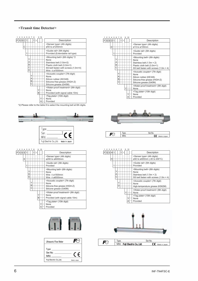
<Transit time Detector>
Description<Senser type> (4th digits)ø50 to ø1200mm
<Mounting belt> (6th digits) *2NoneStainless belt (1.5m×2)Plastic cloth belt (3.0m×1)SS belt fasten with screws (1.0m×4)
<Tag plate> (10th digit)NoneProvided
1F S S C 11 2 3 4 5 6 7 8 9 10
YABCD
<Acoustic coupler> (7th digit)NoneSilicon rubber (KE348)Silicone-free grease (HIGH-Z)Silicone grease (G40M)
YABC
C
<Guide rail> (5th digits)Provided (Extendable rail type) 1
YA
<Water-proof treatment> (9th digit)NoneProvided (with signal cable 10m)
YB
Description<Senser type> (4th digits)ø13 to ø100mm
<Mounting belt> (6th digits)NoneStainless belt (1.5m × 2)
SS belt fasten with screws (1.0m × 4)
<Tag plate> (10th digit)NoneProvided
1F S S D 11 2 3 4 5 6 7 8 9 10
YA
Plastic cloth belt (3.0m×1)BC
<Acoustic coupler> (7th digit)NoneSilicon rubber (KE348)Silicone-free grease (HIGH-Z)Silicone grease (G40M)
YABC
D
<Guide rail> (5th digits)Provided1
YA
<Water-proof treatment> (9th digit)NoneY
Description<Senser type> (4th digits)ø50 to ø400mm (-40 to 200°C)
<Mounting belt> (6th digits)NoneStainless belt (1.5m × 2)SS belt fasten with screws (1.0m × 4)
<Tag plate> (10th digit)NoneProvided
1F S S H 11 2 3 4 5 6 7 8 9 10
YAC
<Acoustic coupler> (7th digit)NoneHigh-temperature grease (KS62M)
YD
H
<Guide rail> (5th digits)Provided1
YA
<Water-proof treatment> (9th digit)NoneY
Description<Senser type> (4th digits)ø200 to ø6000mm
<Mounting belt> (6th digits)None
<Tag plate> (10th digit)NoneProvided
1F S S E 11 2 3 4 5 6 7 8 9 10
YDE
<Acoustic coupler> (7th digit)NoneSilicone-free grease (HIGH-Z)Silicone grease (G40M)
YBC
E
<Guide rail> (5th digits)Provided1
YA
<Water-proof treatment> (9th digit)NoneProvided (with signal cable 10m)
YB
*2) Please refer to the table 8 to select the mounting belt at 6th digits.
Ultrasonic Flow Meter
Type
Mfd.Ser.No.
Made in Japan
Fuji Electric Co., Ltd.Type. Ser.No.Mfd. Made in Japan
Type. Ser.No.Mfd. Made in Japan
INF-TN4FSC-E 7
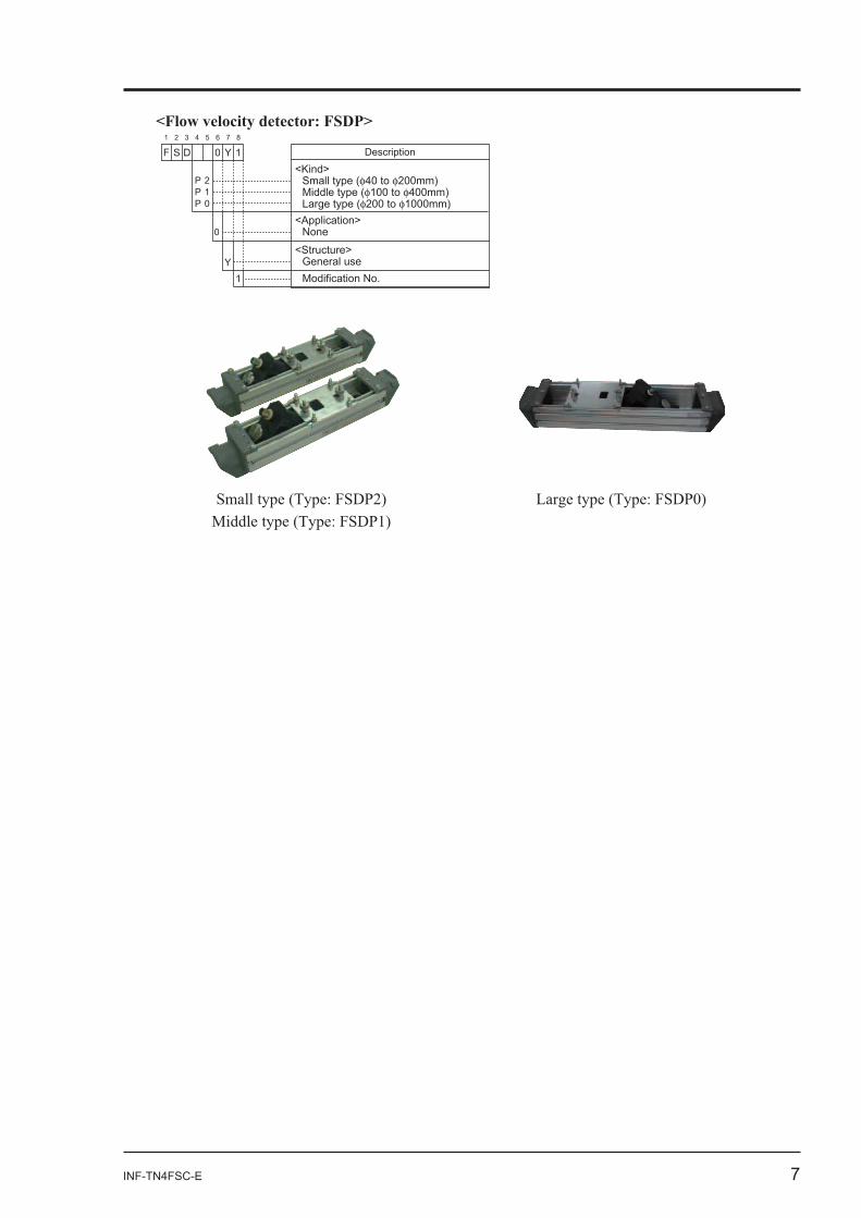
<Flow velocity detector: FSDP>
F DescriptionS D 0 Y 11 2 3 4 5 6 7 8
<Kind>Small type ( 40 to 200mm)Middle type ( 100 to 400mm)Large type ( 200 to 1000mm)
<Structure>General use
PPP
210
0
Y
<Application>None
1 Modification No.
8 INF-TN4FSC-E
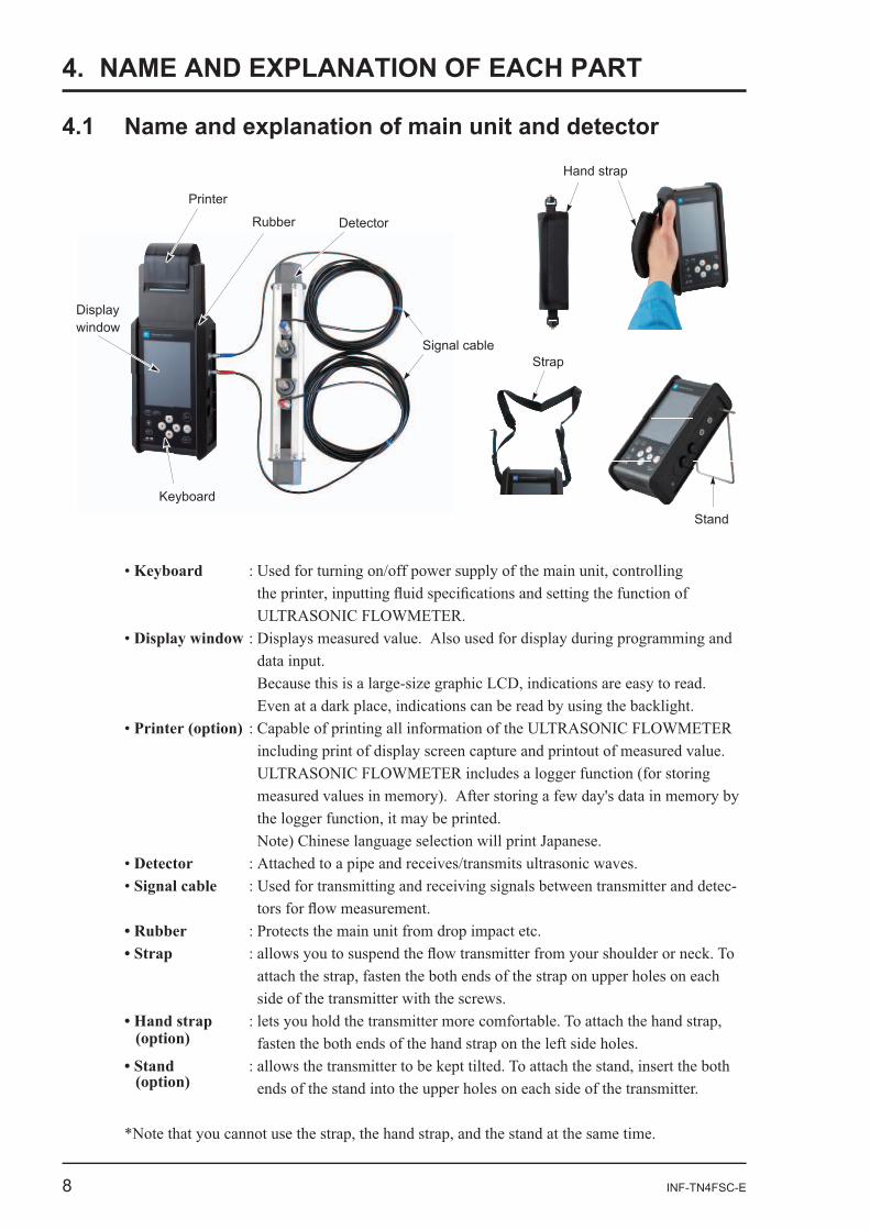
4. NAME AND EXPLANATION OF EACH PART
Keyboard
Display window
Printer (option)
DetectorSignal cable
Keyboard
Display window
Detector
Printer
Rubber
Signal cable
Hand strap
Strap
Stand
(option)
(option)
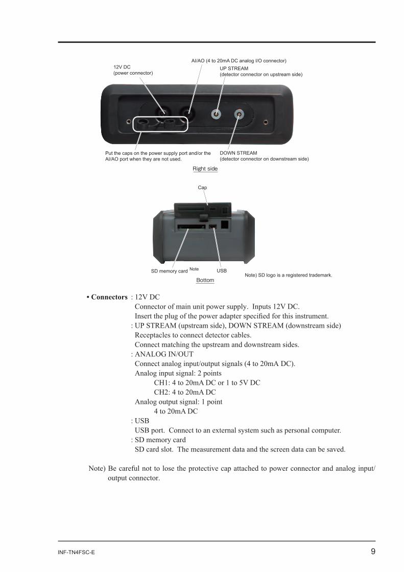
INF-TN4FSC-E 9
12V DC(power connector)
AI/AO (4 to 20mA DC analog I/O connector)UP STREAM (detector connector on upstream side)
DOWN STREAM (detector connector on downstream side)
Right side
SD memory cardNote) SD logo is a registered trademark.
Note
Cap
USB
Bottom
Put the caps on the power supply port and/or the AI/AO port when they are not used.
10 INF-TN4FSC-E
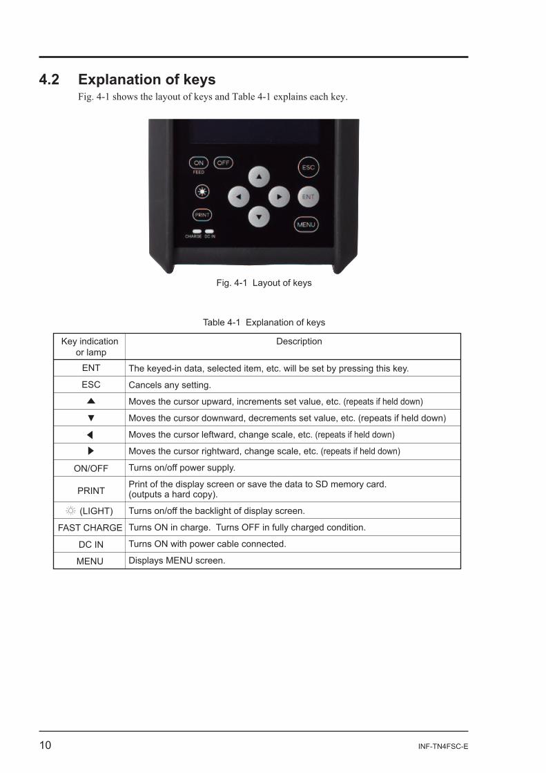
Fig. 4-1 Layout of keys
Table 4-1 Explanation of keys
Description
The keyed-in data, selected item, etc. will be set by pressing this key.
Cancels any setting.
Moves the cursor upward, increments set value, etc. (repeats if held down)
Moves the cursor downward, decrements set value, etc. (repeats if held down)
Moves the cursor leftward, change scale, etc. (repeats if held down)
Moves the cursor rightward, change scale, etc. (repeats if held down)
Turns on/off power supply.
Print of the display screen or save the data to SD memory card. (outputs a hard copy).
Turns on/off the backlight of display screen.
Turns ON in charge. Turns OFF in fully charged condition.
Turns ON with power cable connected.
Displays MENU screen.
Key indication or lamp
ENT
ESC
ON/OFF
(LIGHT)
FAST CHARGE
DC IN
MENU
INF-TN4FSC-E 11
4.3.1 Handling notice
--
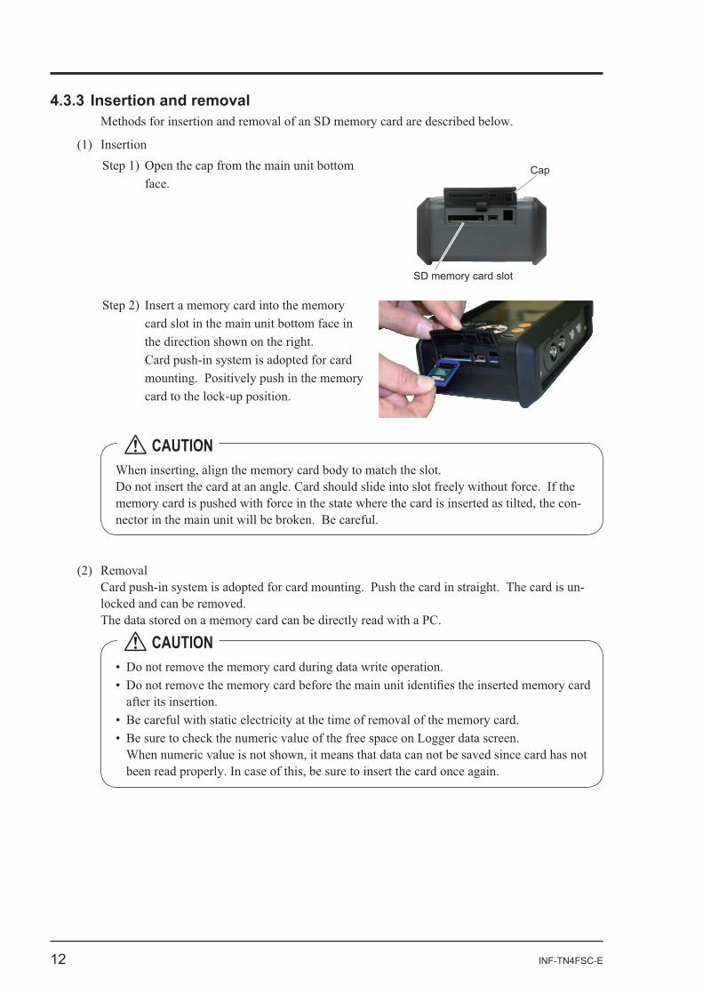
12 INF-TN4FSC-E
SD memory card slot
Cap
-
CAUTION
-
CAUTION
INF-TN4FSC-E 13
(1) Types of recorded data
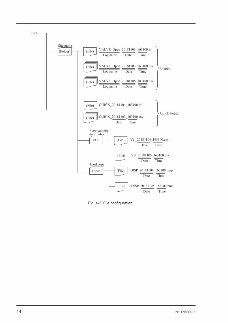
14 INF-TN4FSC-E
Root
(Folder) Site name
VALVE_Open_20181103_163100.csvDate Time
QUICK_20181104_163100.ini
Logger
(File)
(File)
(File)
QUICK_20181103_163100.csv Date Time
Quick logger
VEL
Flow velocity distribution
Vel_20181104_163100.csv Data Time
Vel_20181105_163100.csv Date Time
DISP
Hard copy DISP_20181104_163100.bmp
Date Time
DISP_20181105_163100.bmp Date Time
VALVE_Open_20181105_183100.csv Date Time
VALVE_Open_20181103_163100.iniDate TimeLog name
Log name
Log name(File)
(File)
(File)
(File)
(File)
(File)
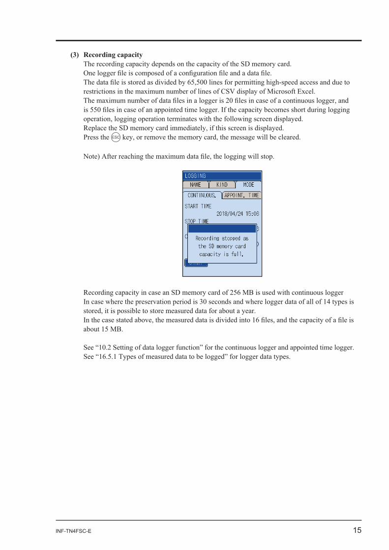
INF-TN4FSC-E 15
Press the ESC
16 INF-TN4FSC-E
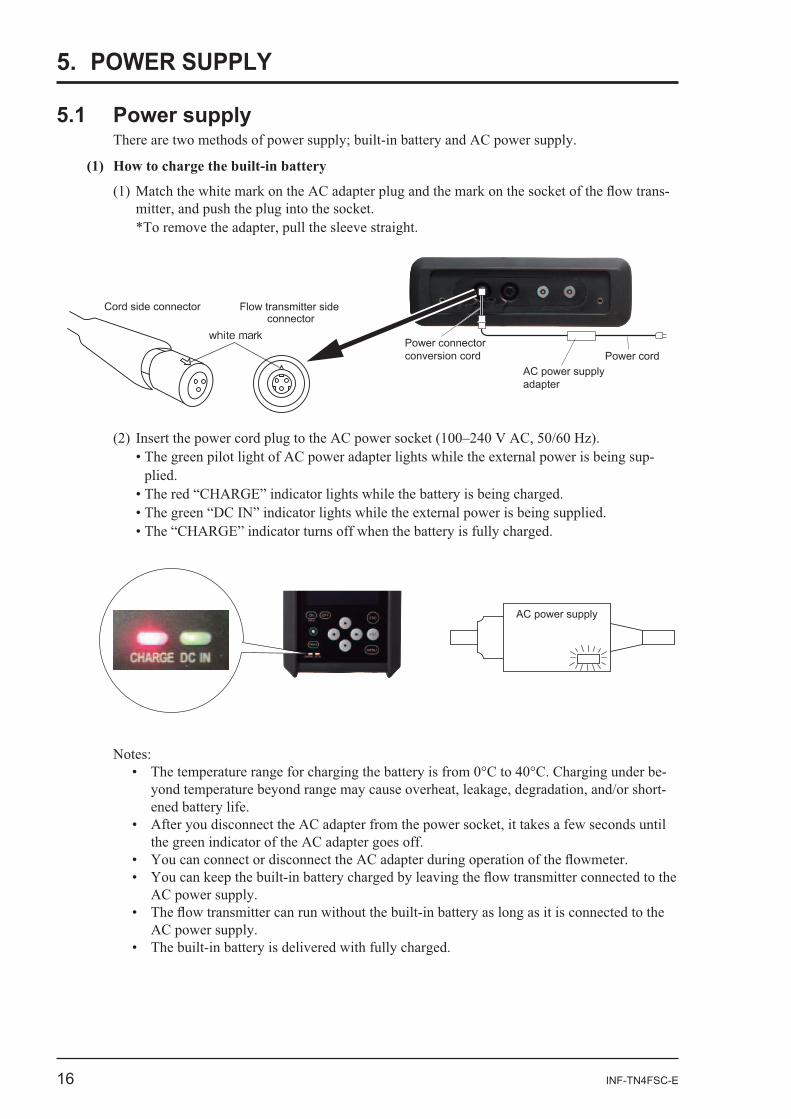
5. POWER SUPPLY
-
AC power supply
Power connector conversion cord
AC power supply adapter
Power cord
white mark
Cord side connector Flow transmitter side connector
-
Notes:--
INF-TN4FSC-E 17
(3) Operating by AC power adapter for a prolonged time
-
CAUTION
18 INF-TN4FSC-E
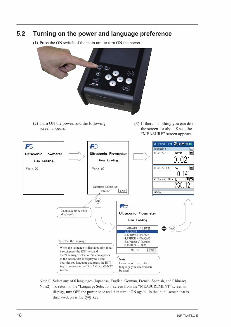
screen in
ENT
ENT
ENT
Language to be set is displayed.
To select the language
Note: From the next step, the language you selected can be used.
When the language is displayed (for about 8 sec.), press the ENT key, and the “Language Selection”screen appears. In the screen that is displayed, selectyour desired language and press the ENT key. It returns to the “MEASUREMENT” screen.
INF-TN4FSC-E 19
-
CAUTION
20 INF-TN4FSC-E
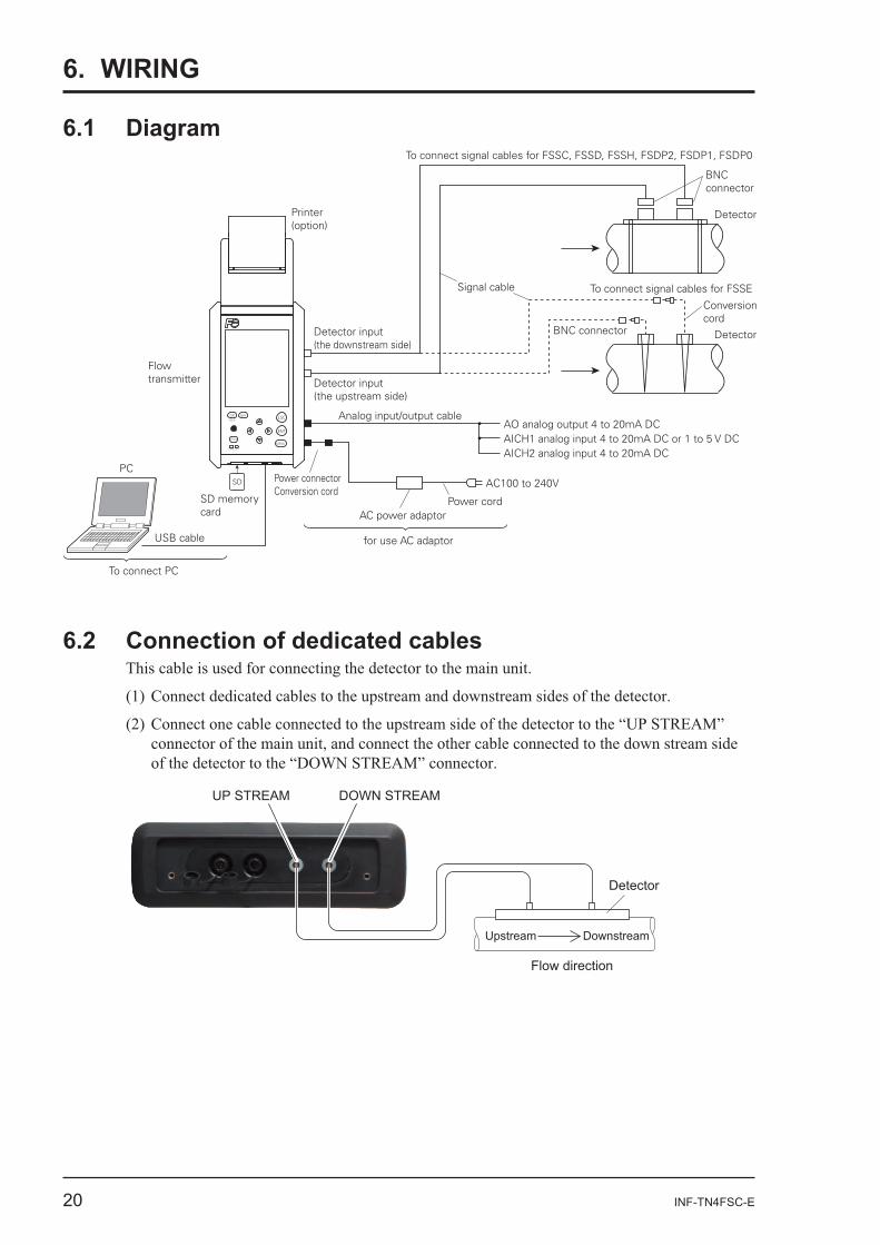
6. WIRING
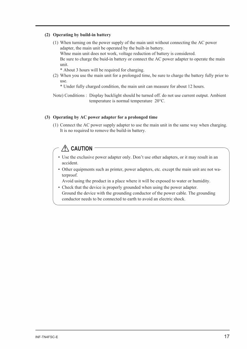
SD
CHARGE DC IN
FEEDESCON OFF
ENT
MENU
Printer (option)
Detector
Detector
Conversioncord
Signal cable
To connect signal cables for FSSC, FSSD, FSSH, FSDP2, FSDP1, FSDP0
To connect signal cables for FSSE
BNC connector
BNC connector
AO analog output 4 to 20mA DCAICH1 analog input 4 to 20mA DC or 1 to 5 V DCAICH2 analog input 4 to 20mA DC
Analog input/output cable
AC100 to 240V
Power cordAC power adaptor
Power connector Conversion cord
To connect PC
PC
Flowtransmitter
USB cable
SD memory card
for use AC adaptor
Detector input (the downstream side)
Detector input (the upstream side)
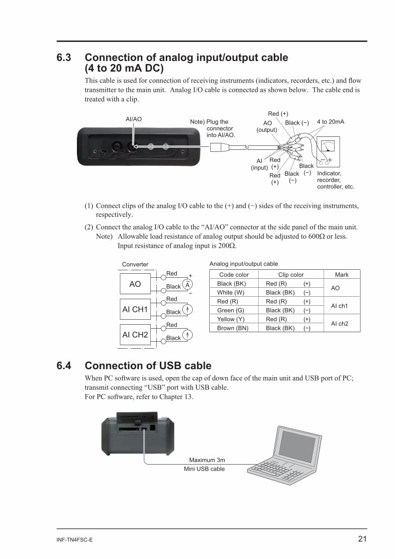
6.2 Connection of dedicated cables
DOWN STREAMUP STREAM
Upstream Downstream
Flow direction
Detector
INF-TN4FSC-E 21
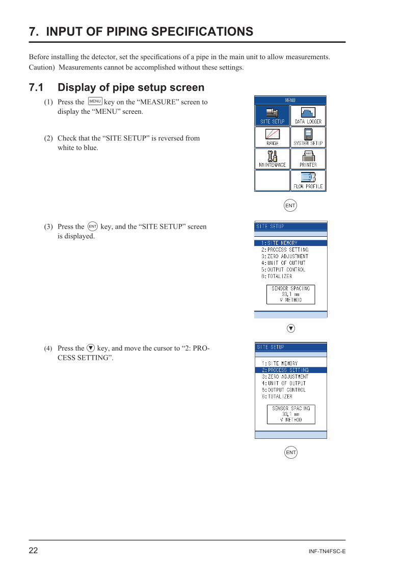
6.3 Connection of analog input/output cable
Red (+)
Red(+)
Black
4 to 20mA
-+
AO(output)
AI/AO Note) Plug the connector into AI/AO.
AI(input)
Indicator, recorder, controller, etc.
Red(+) Black
AI ch2
AOAI ch1
RedConverter
Black
Red
Black
Red
Black
AO
AI CH1
AI CH2
+A
6.4 Connection of USB cable
Mini USB cableMaximum 3m
Analog input/output cable
Code color Clip color MarkBlack (BK) Red (R) (+)
AOWhite (W)Red (R) Red (R) (+)
AI ch1Green (G)Yellow (Y) Red (R) (+)
AI ch2Brown (BN)
22 INF-TN4FSC-E
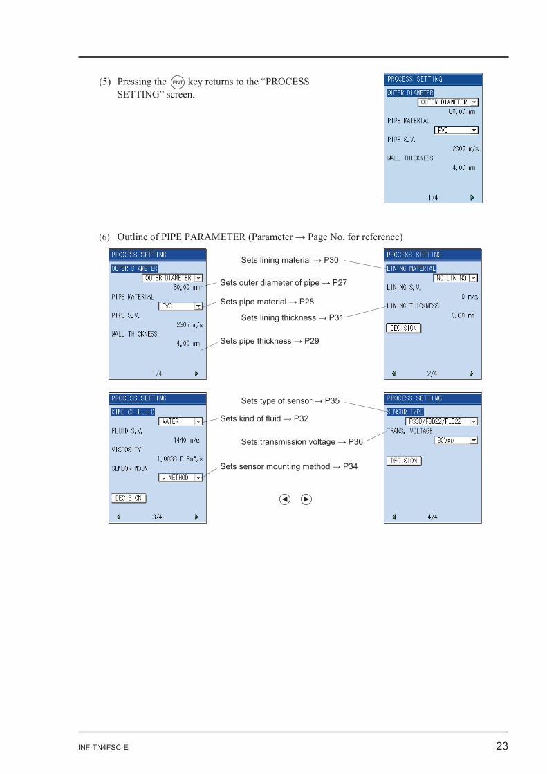
7. INPUT OF PIPING SPECIFICATIONS
7.1 Display of pipe setup screenMENU
ENT
ENT
Press the -
ENT
INF-TN4FSC-E 23
ENT
Sets outer diameter of pipe
Sets pipe material
Sets pipe thickness
Sets sensor mounting method
Sets lining material
Sets lining thickness
Sets type of sensor
Sets transmission voltage
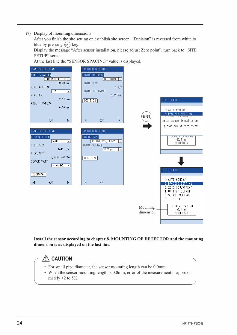
24 INF-TN4FSC-E
ENT
ENT
Mounting dimension
-
CAUTION
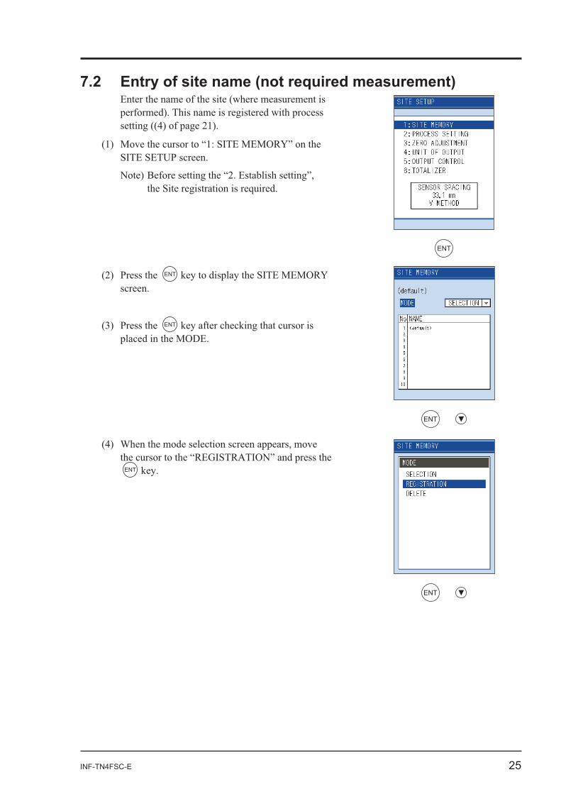
INF-TN4FSC-E 25
ENT
ENT
ENT
ENT
ENT
ENT
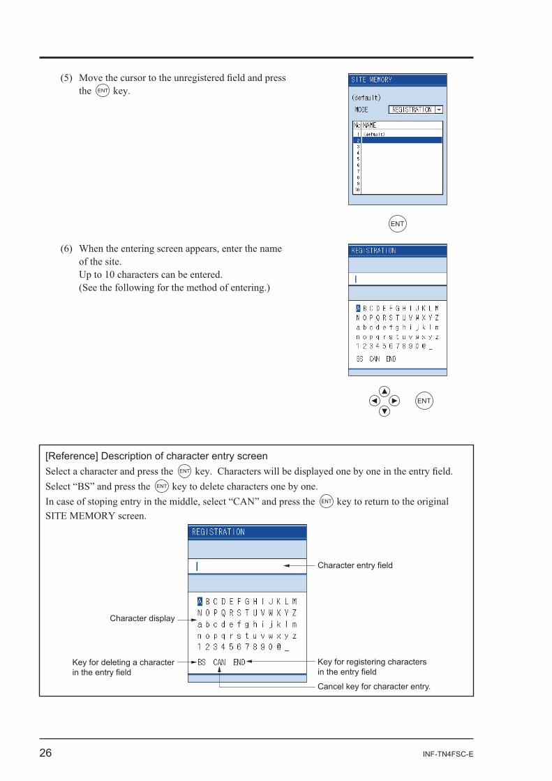
26 INF-TN4FSC-E
the ENT
ENT
ENT
[Reference] Description of character entry screenSelect a character and press the ENT
ENT
ENT
Character entry field
Key for registering characters in the entry field
Cancel key for character entry.
Character display
Key for deleting a character in the entry field
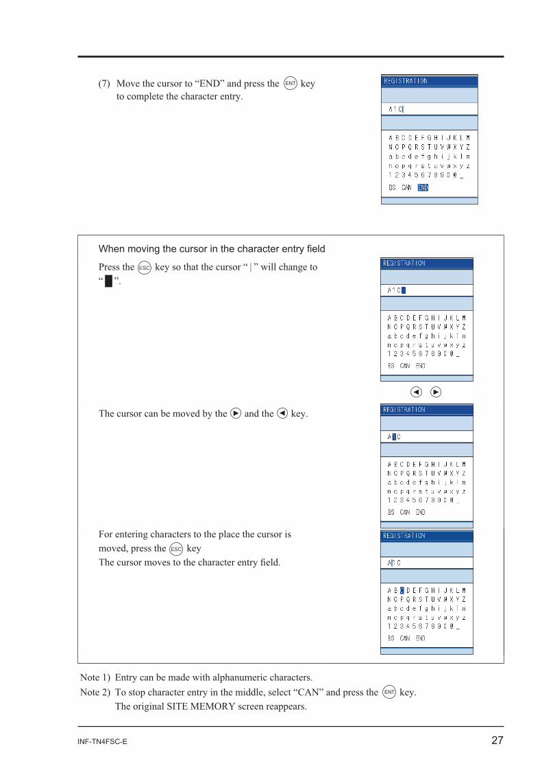
INF-TN4FSC-E 27
ENT
Press the ESC
and the
ESC
ENT
28 INF-TN4FSC-E
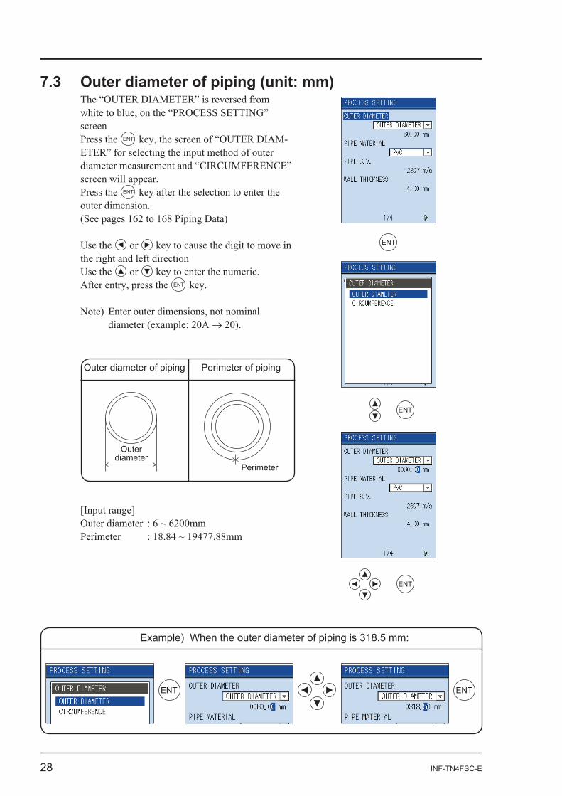
screen Press the ENT -
Press the ENT
or
or ENT
ENT
ENT
ENT
Example) When the outer diameter of piping is 318.5 mm:
ENT ENT
Outerdiameter
Perimeter
Outer diameter of piping Perimeter of piping
INF-TN4FSC-E 29
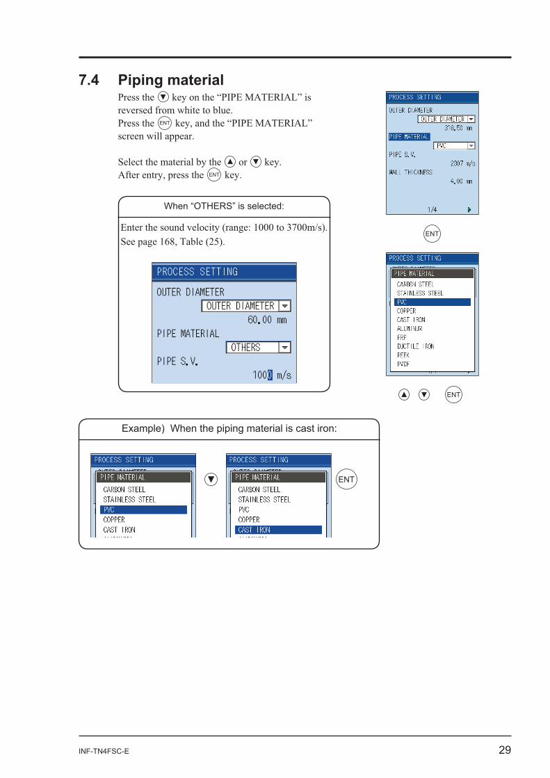
Press the
Press the ENT
or ENT
When “OTHERS” is selected:
ENT
ENT
ENT
Example) When the piping material is cast iron:
30 INF-TN4FSC-E
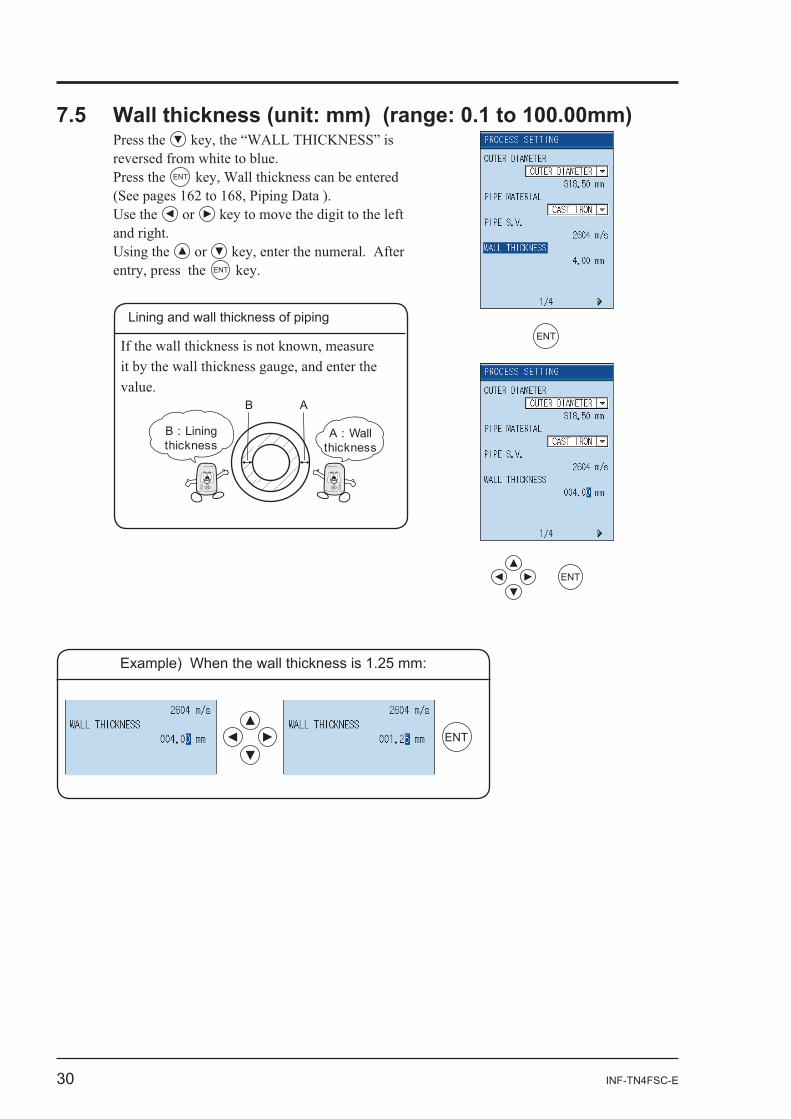
Press the
Press the ENT
or
or ENT
B : Liningthickness
B
A : Wallthickness
A
Lining and wall thickness of pipingENT
ENT
ENT
Example) When the wall thickness is 1.25 mm:
INF-TN4FSC-E 31
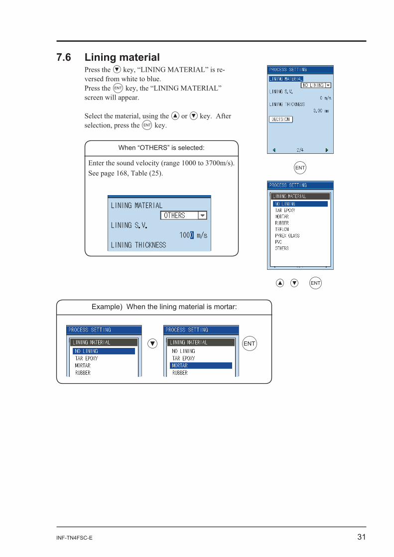
Press the -
Press the ENT
or ENT
When “OTHERS” is selected:
ENT
ENT
ENT
Example) When the lining material is mortar:
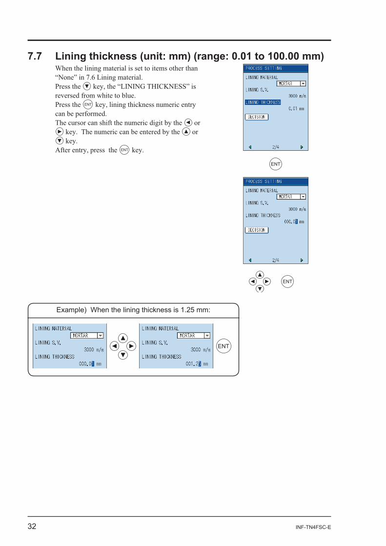
32 INF-TN4FSC-E
Press the
Press the ENT
or or
ENT
ENT
ENT
ENT
Example) When the lining thickness is 1.25 mm:
INF-TN4FSC-E 33
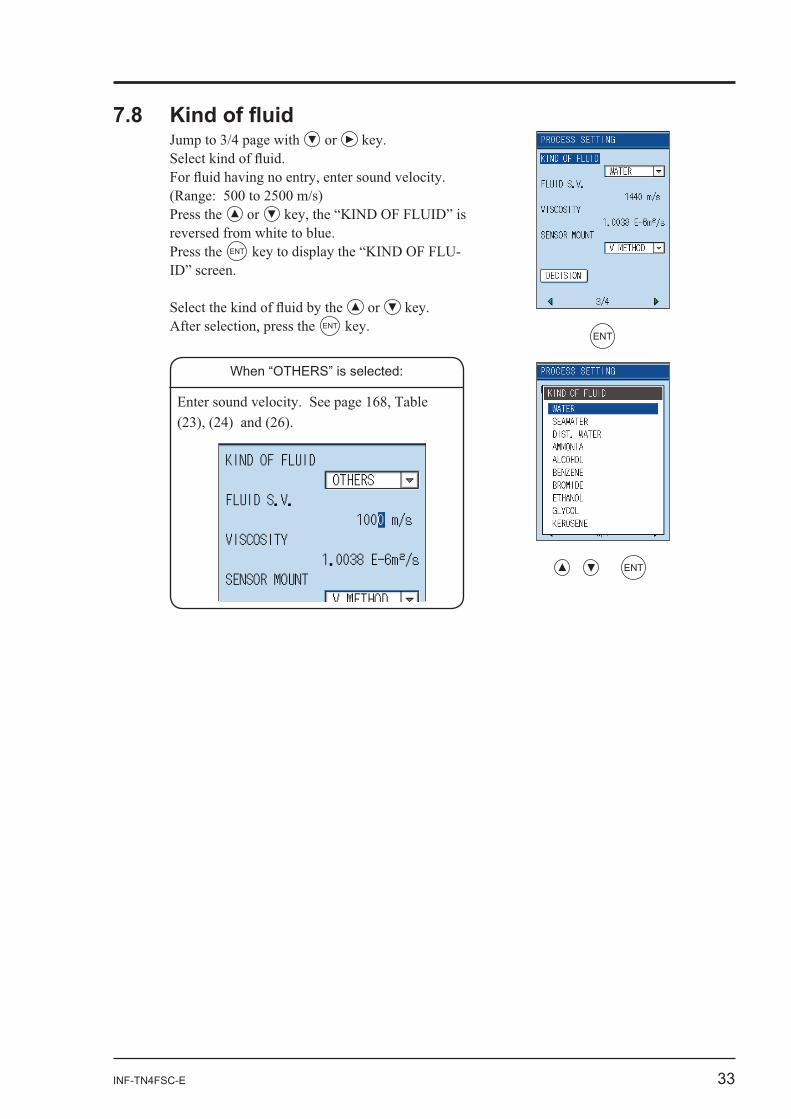
or
Press the or
Press the ENT -
or ENT
When “OTHERS” is selected:
ENT
ENT
34 INF-TN4FSC-E
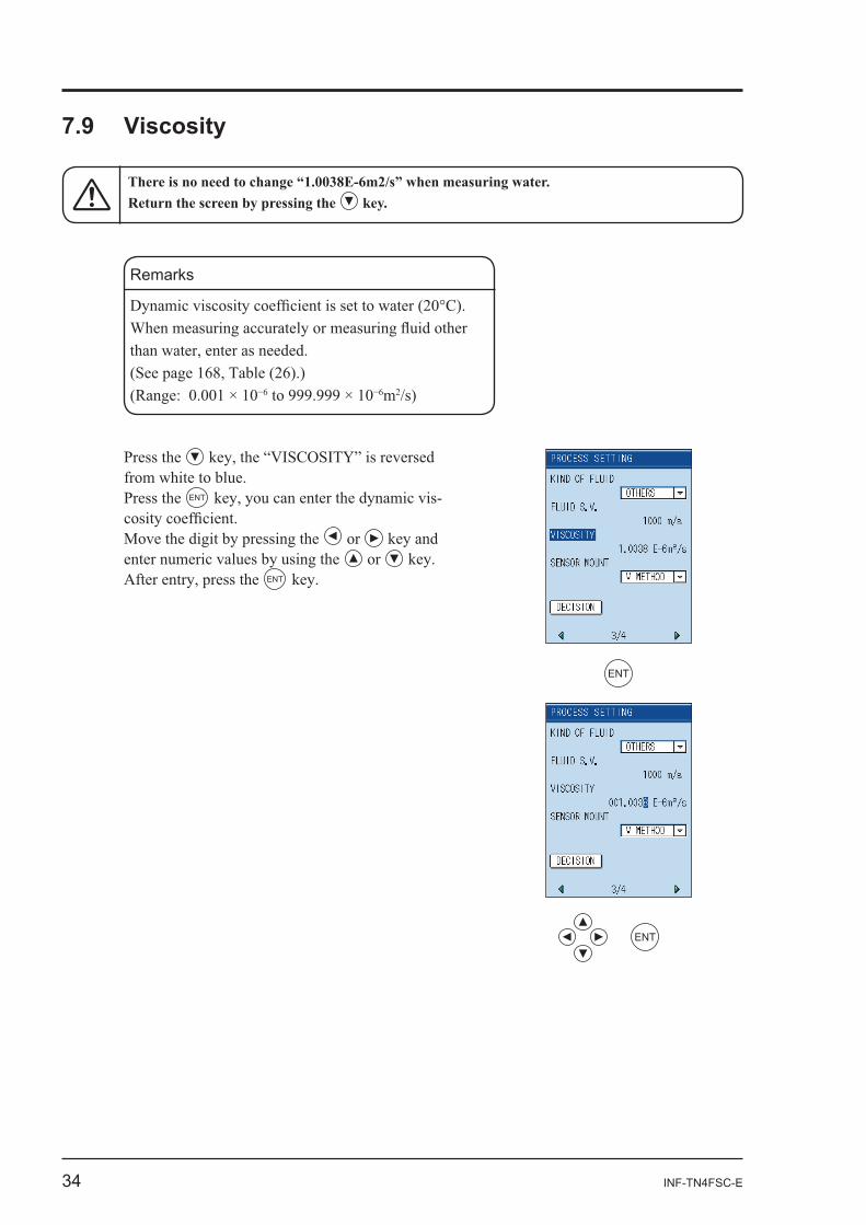
7.9 Viscosity
Remarks
/s)
Press the
Press the ENT -
or or
ENT
ENT
ENT
INF-TN4FSC-E 35
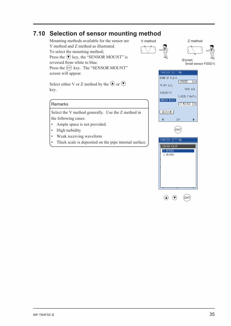
Press the
Press the ENT
or
Remarks
V method Z method
(Except. Small sensor FSSD1)
ENT
ENT
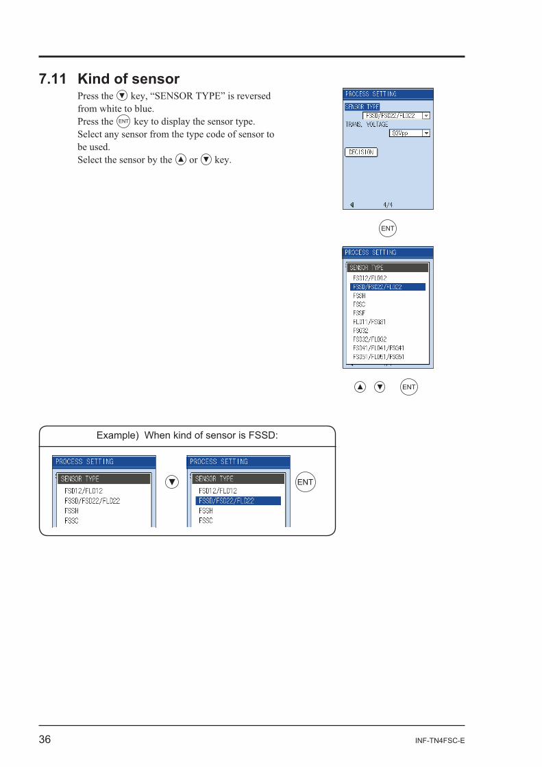
36 INF-TN4FSC-E
7.11 Kind of sensorPress the
Press the ENT
Select the sensor by the or
ENT
ENT
ENT
Example) When kind of sensor is FSSD:
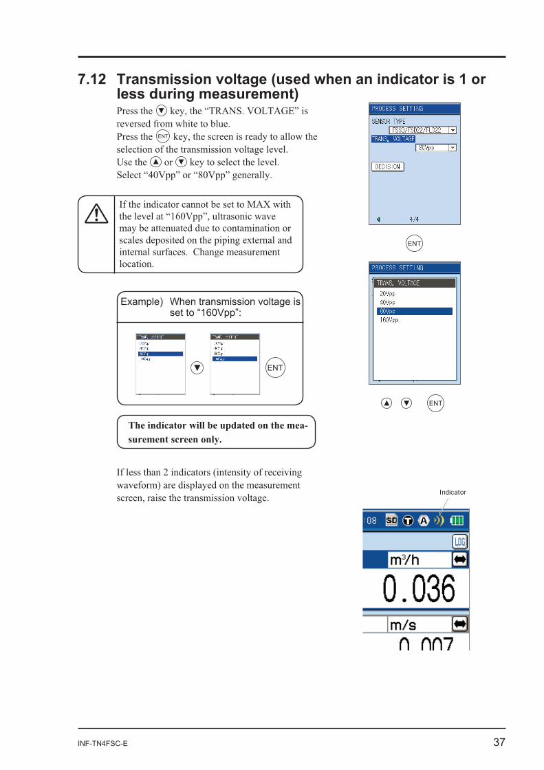
INF-TN4FSC-E 37
Press the
Press the ENT
or
Example) When transmission voltage is set to “160Vpp”:
ENT
ENT
ENT
Indicator
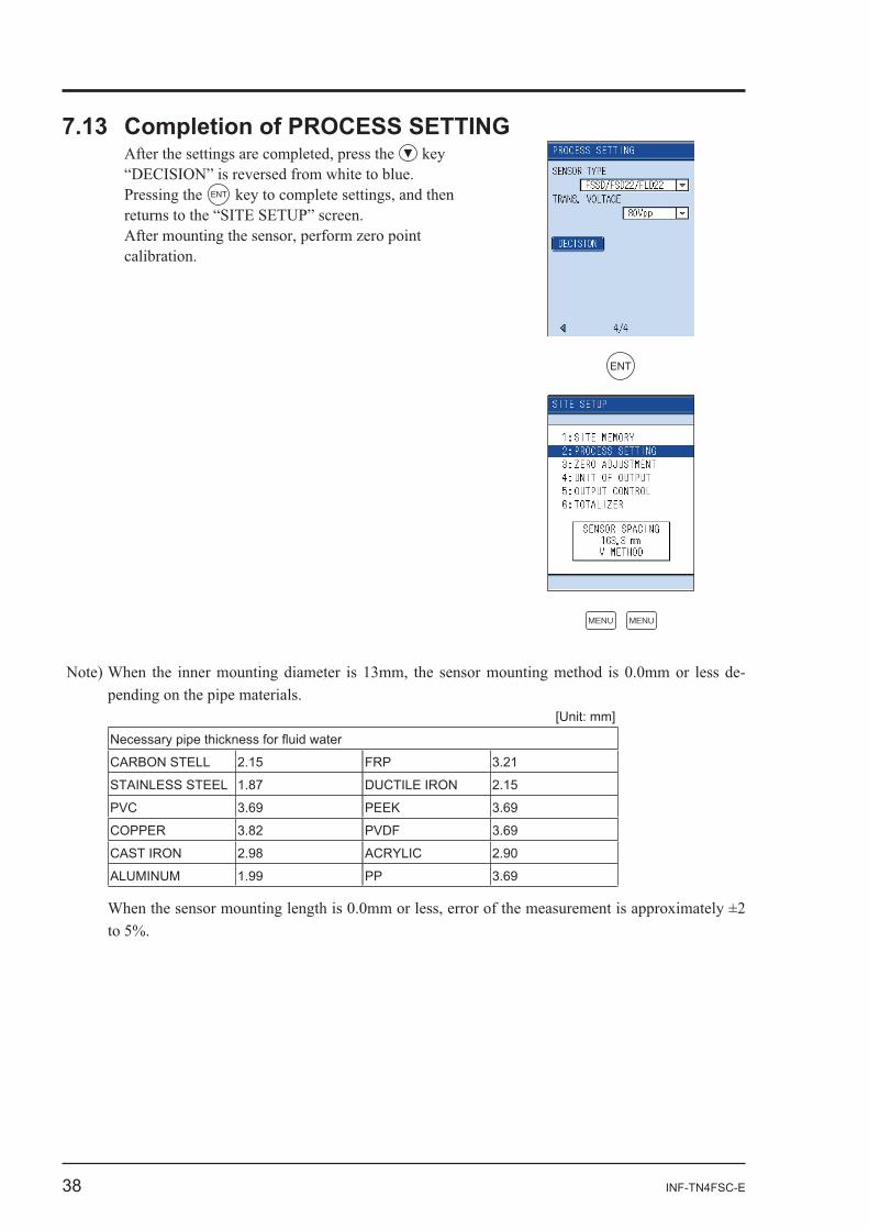
38 INF-TN4FSC-E
ENT
ENT
MENU MENU
-
[Unit: mm]
CARBON STELL 2.15 FRP 3.21
STAINLESS STEEL 1.87 DUCTILE IRON 2.15
PVC 3.69 PEEK 3.69
COPPER 3.82 PVDF 3.69
CAST IRON 2.98 ACRYLIC 2.90
ALUMINUM 1.99 PP 3.69
INF-TN4FSC-E 39
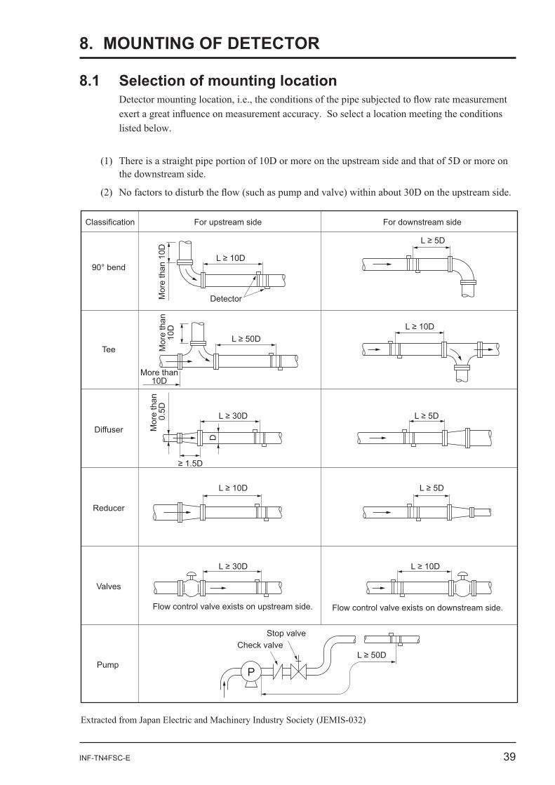
8. MOUNTING OF DETECTOR
P
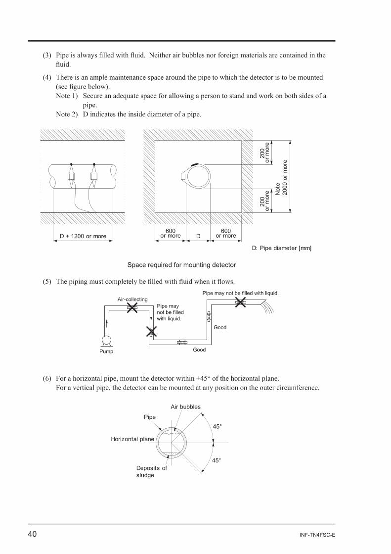
40 INF-TN4FSC-E
D + 1200 or more600
or more D600
or more
200
or m
ore
200
or m
ore
Not
e20
00 o
r m
ore
D: Pipe diameter [mm]
Space required for mounting detector
Pump
Air-collecting
Good
Good
Pipe may not be filled with liquid.
Pipe may not be filled with liquid.
Horizontal plane
Pipe
Deposits of sludge
Air bubbles
45°
45°
INF-TN4FSC-E 41
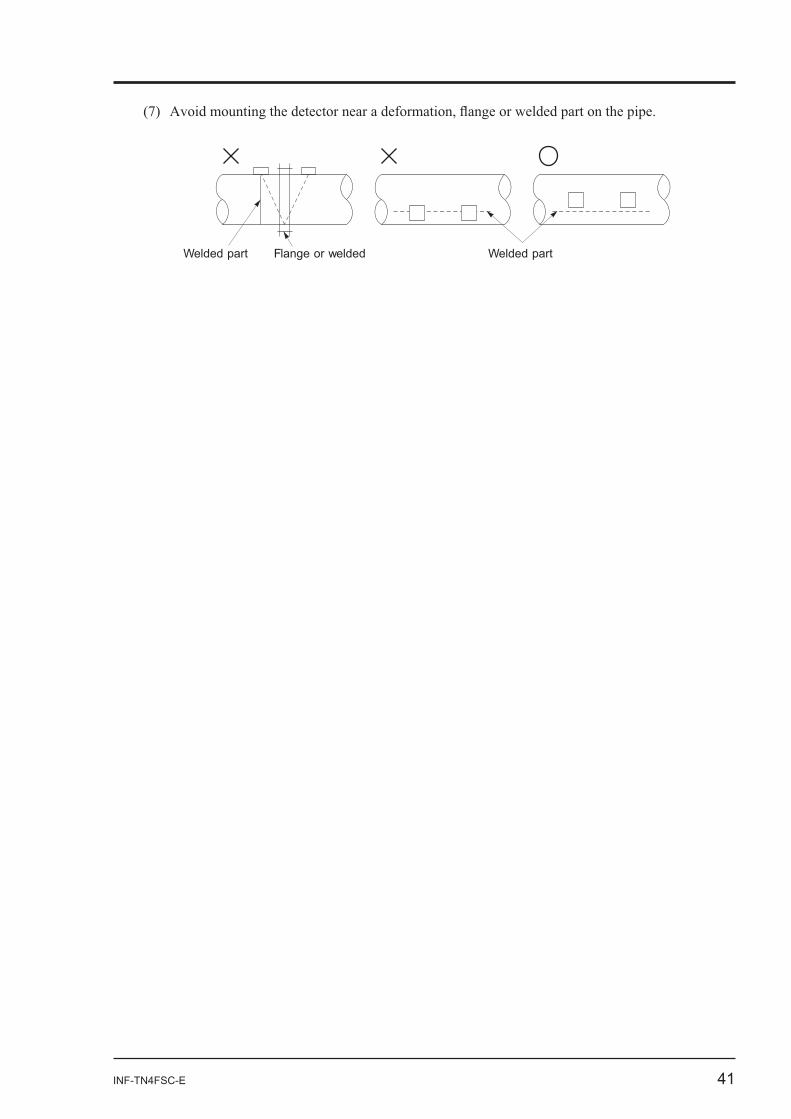
Welded part Flange or welded Welded part
42 INF-TN4FSC-E
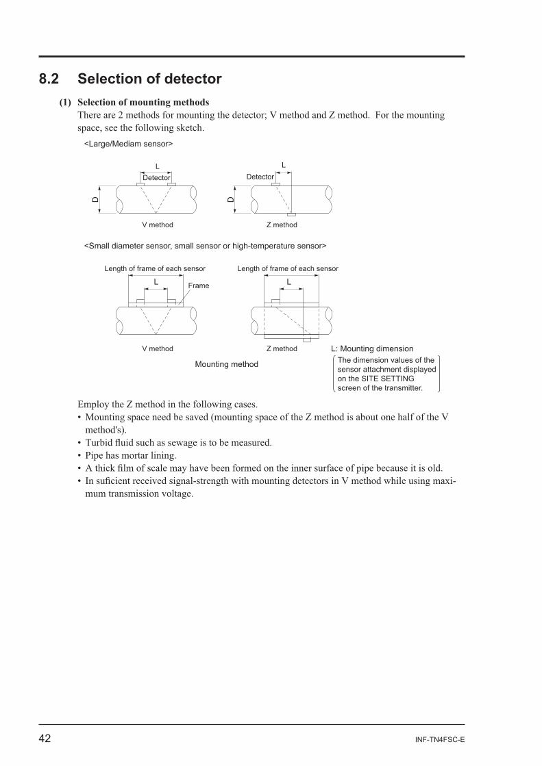
8.2 Selection of detector
Length of frame of each sensor
Frame
Length of frame of each sensor
L L
L: Mounting dimension
<Small diameter sensor, small sensor or high-temperature sensor>
D D
<Large/Mediam sensor>
DetectorL
V method
DetectorL
Z method
V method Z method
Mounting method The dimension values of the sensor attachment displayed on the SITE SETTING screen of the transmitter.
-
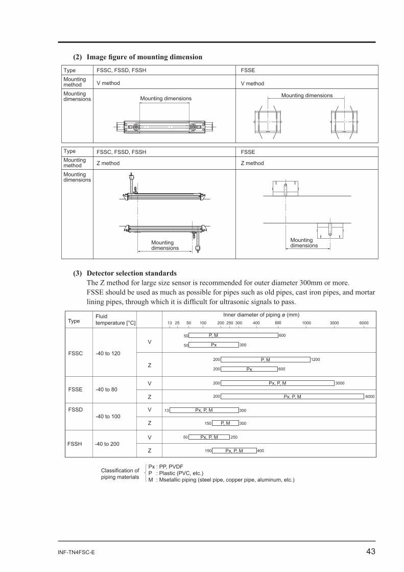
INF-TN4FSC-E 43
FSSEFSSC, FSSD, FSSHType
V methodV method
Z method Z method
Mounting dimensions
Mounting dimensionsMounting
dimensions
Mounting dimensions
MountingmethodMountingdimensions
TypeMountingmethodMountingdimensions
FSSC, FSSD, FSSH FSSE
(3) Detector selection standards
Z
VFSSE
FSSD
VFSSH
Z
V
Z
V
FSSC -40 to 120
-40 to 80
-40 to 100
-40 to 200
13 25 50 100 200 300 400 1000 3000 6000250TypeFluid temperature [°C]
Inner diameter of piping ø (mm)
Px
Px, P, M
Px, P, M
Px, P, M
P, M
Px, P, M
Px, P, M
30013
Z P, M 300150
50
50
150 400
250
200 1200
Px200 600
200 3000
6000200
300
P, M50 600
Px : PP, PVDFP : Plastic (PVC, etc.)M : Msetallic piping (steel pipe, copper pipe, aluminum, etc.)
Classification of piping materials
44 INF-TN4FSC-E
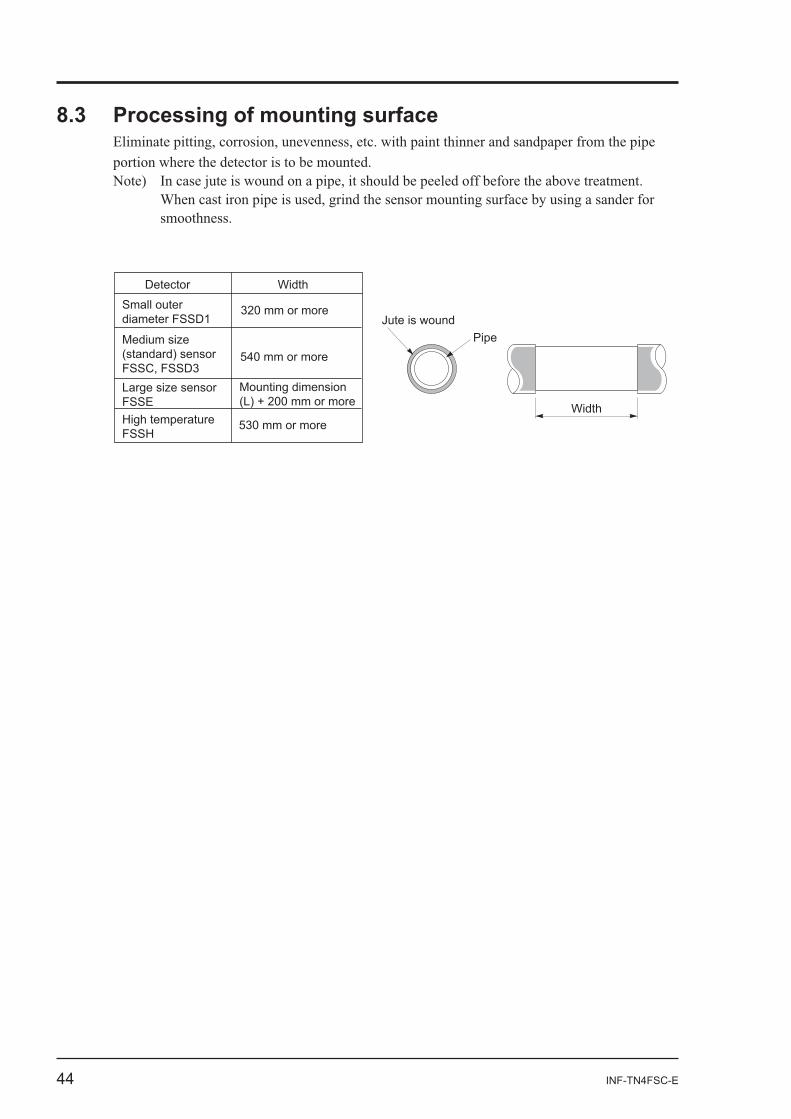
Jute is wound
Detector Width
Pipe
Width
Small outer diameter FSSD1
320 mm or more
Medium size (standard) sensorFSSC, FSSD3
540 mm or more
Large size sensorFSSE
Mounting dimension (L) + 200 mm or more
High temperatureFSSH
530 mm or more
INF-TN4FSC-E 45
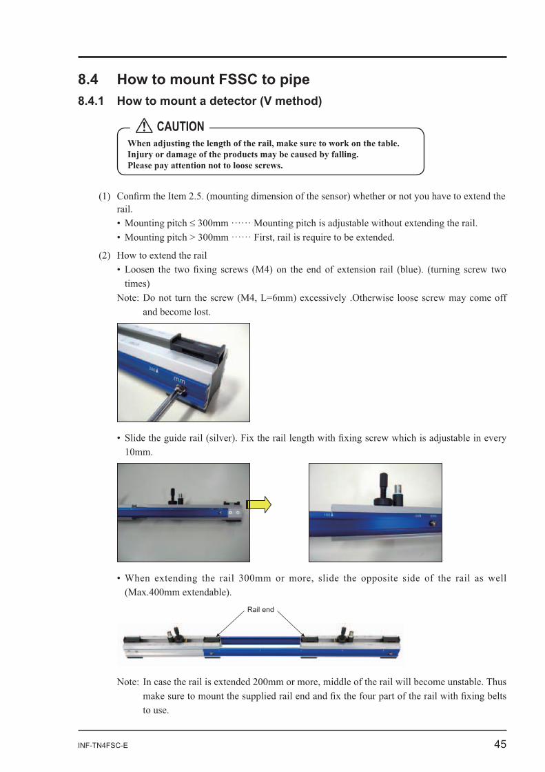
Rail end
CAUTION
46 INF-TN4FSC-E
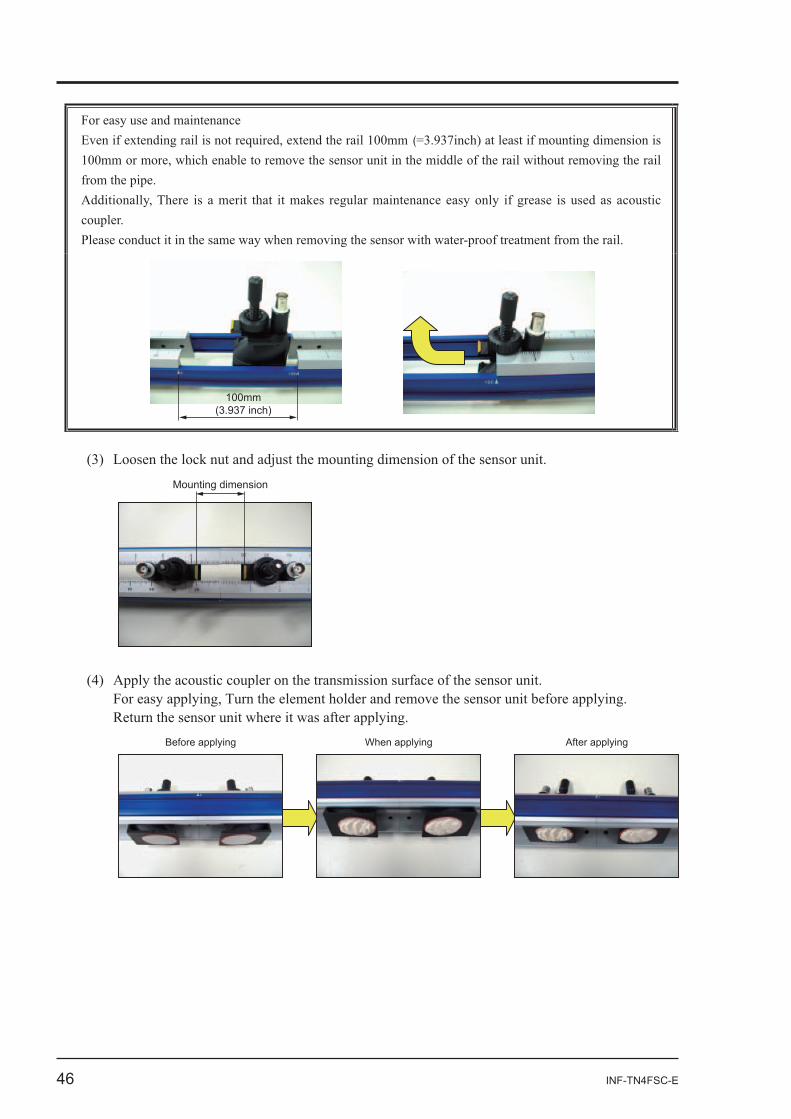
(
100mm(3.937 inch)
Mounting dimension
Before applying When applying After applying
INF-TN4FSC-E 47
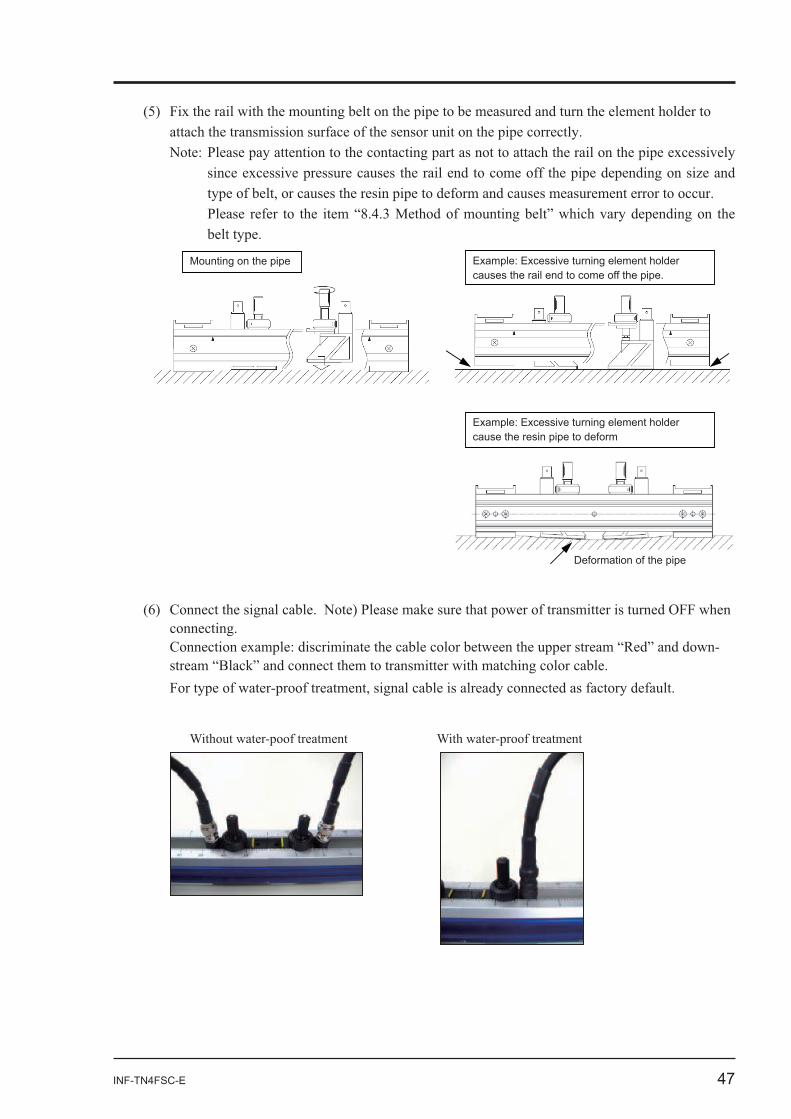
Mounting on the pipe Example: Excessive turning element holder causes the rail end to come off the pipe.
Example: Excessive turning element holder cause the resin pipe to deform
Deformation of the pipe
-
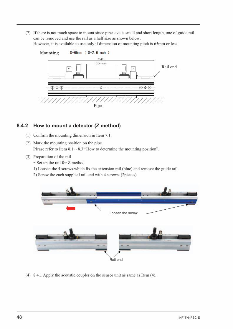
48 INF-TN4FSC-E
Mounting
Rail end
Pipe
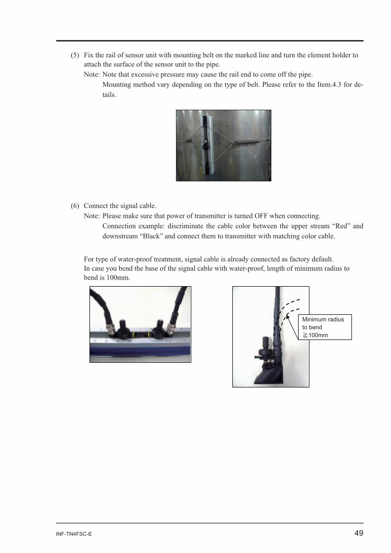
Rail end
Loosen the screw
INF-TN4FSC-E 49
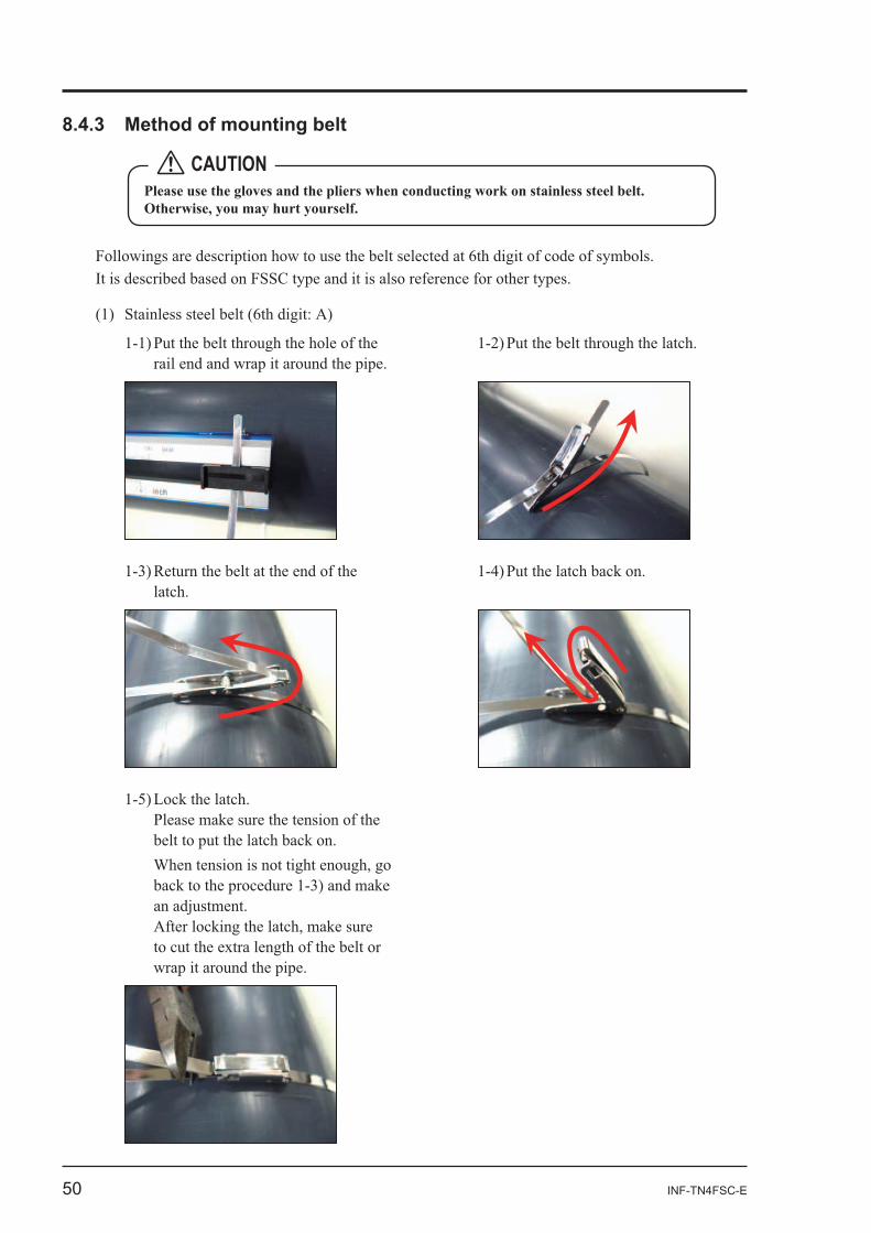
-
Minimum radius to bend
100mm
50 INF-TN4FSC-E
CAUTION
INF-TN4FSC-E 51
52 INF-TN4FSC-E
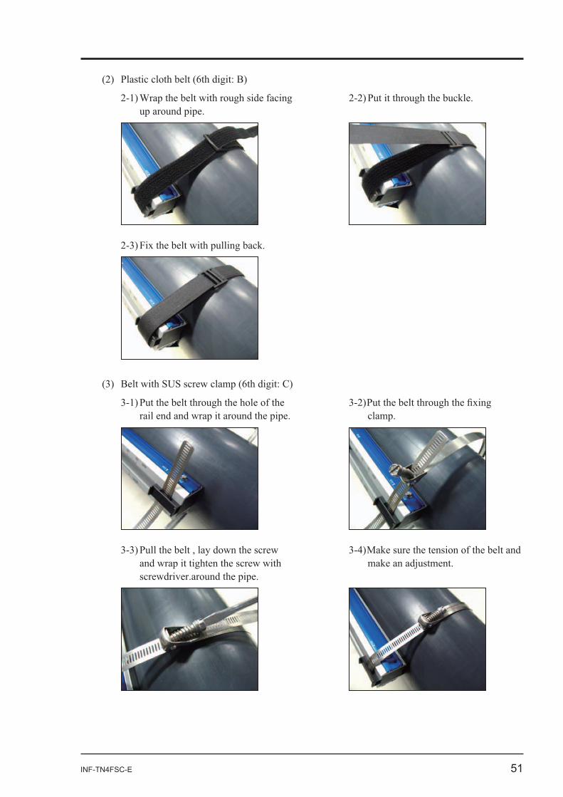
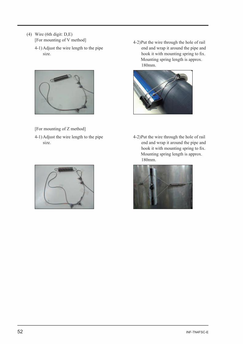
end and wrap it around the pipe and
end and wrap it around the pipe and
INF-TN4FSC-E 53
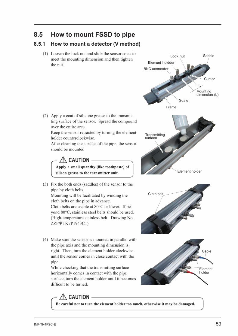
Element holdder
Lock nut Saddle
Scale
Cursor
Mounting dimension (L)
Frame
BNC connector
-
Transmitting surface
Element holder
-
Cloth belt
Element holder
Cable
CAUTION
CAUTION
54 INF-TN4FSC-E
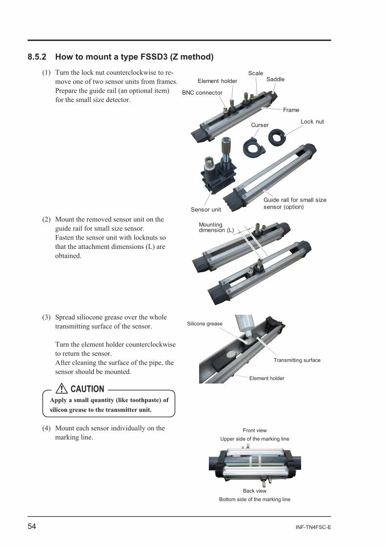
- Element holder
Lock nut
Sensor unit
SaddleScale
Curser
Frame
BNC connector
Guide rall for small size sensor (option)
Mounting dimension (L)
Element holder
Silicone grease
Transmitting surface
Front view
Back view
Upper side of the marking line
Bottom side of the marking line
CAUTION
INF-TN4FSC-E 55
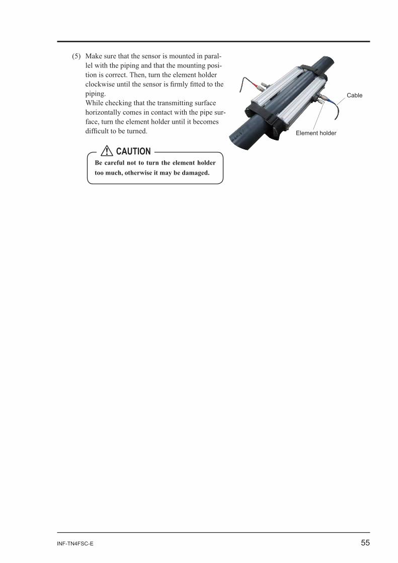
--
-
Element holder
Cable
CAUTION
56 INF-TN4FSC-E
-
Align this edge.
100mmLine drawn on gauge paper
Draw line A.
Draw a linealong the edge. A0
-
A0A2
200mm
-
A0A1
B1 B0 Straight line B
A0, A1B0, B1
to
B2
B2
B0
B0
100mm A0
INF-TN4FSC-E 57
Cover
-
Cable clamp
Conversion cord
CAUTION
CAUTION
58 INF-TN4FSC-E
BNC connector
Conversion cord
Signal cable
Pipe
Guide plateFixing screw
Transmissionsurface
Transmissiondirection mark
180
600
Sensor
Marked lines
Fasteningspring
Loosen this wire clipand pull the wire rope.
Pipe
INF-TN4FSC-E 59
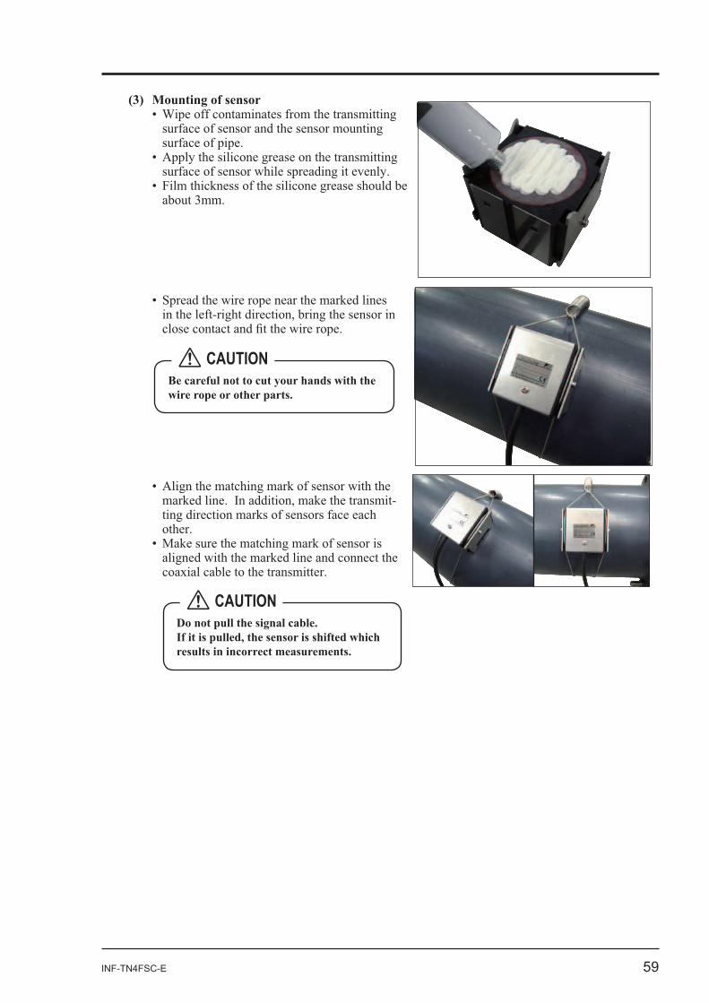
(3) Mounting of sensor
-
CAUTION
CAUTION
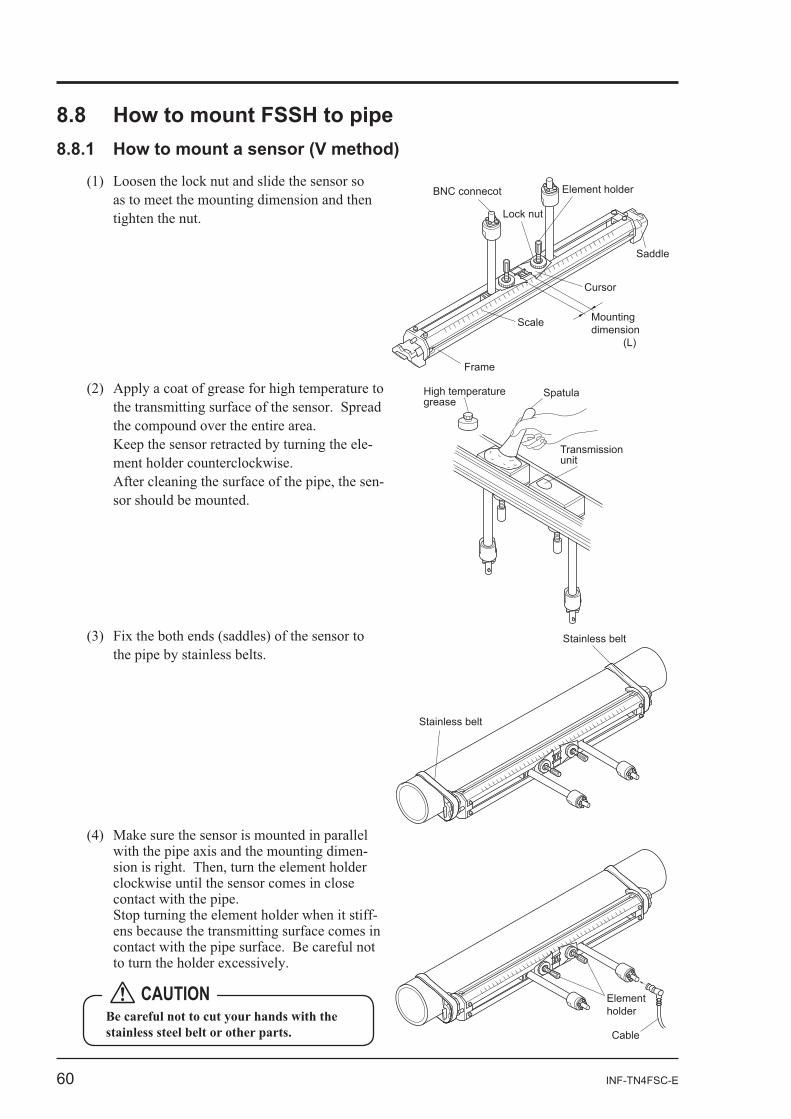
60 INF-TN4FSC-E
BNC connecot Element holder
Lock nut
Saddle
Cursor
Frame
Scale Mounting dimension (L)
-
-
High temperature grease
Spatula
Transmission unit
Stainless belt
Stainless belt
-
-
Element holder
Cable
CAUTION
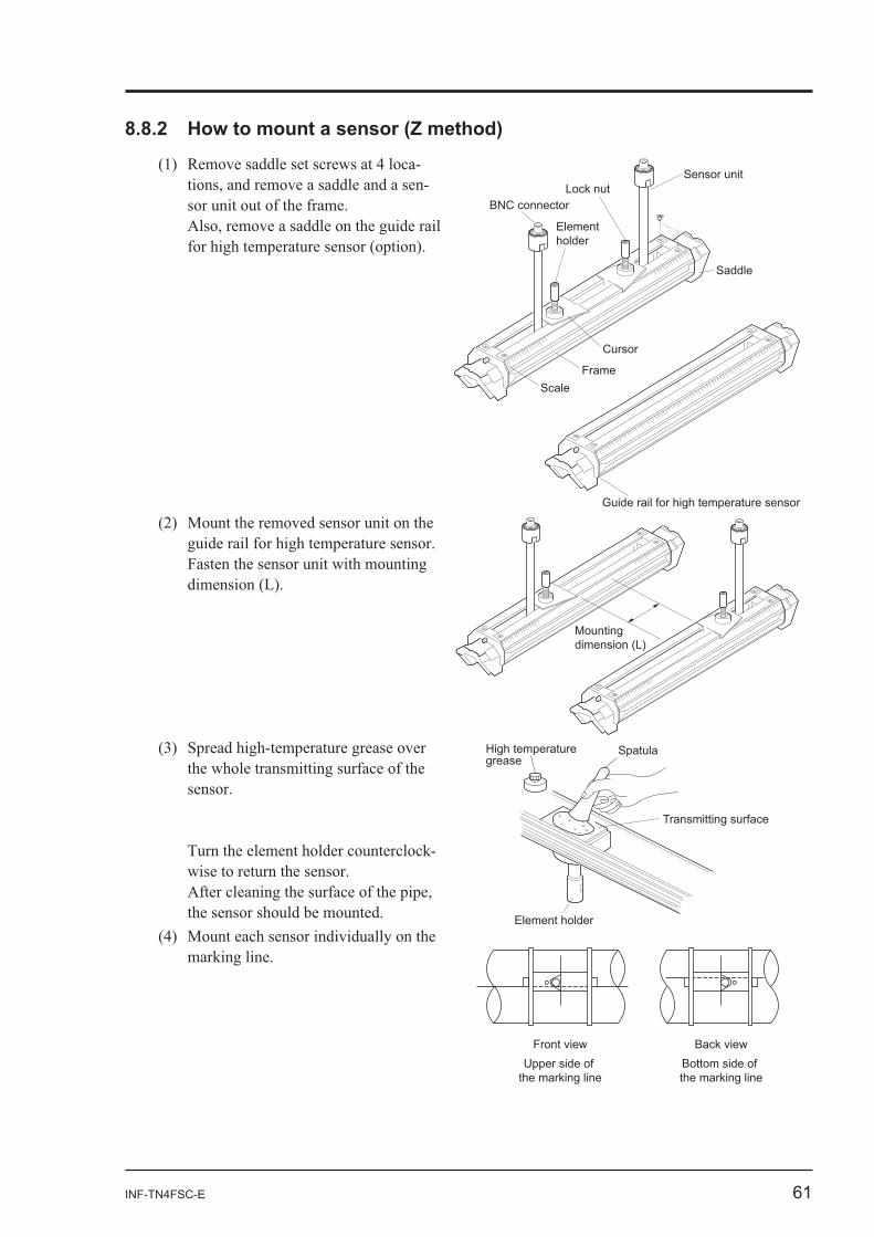
INF-TN4FSC-E 61
--
BNC connector
Elementholder
Lock nut
Saddle
Cursor
FrameScale
Guide rail for high temperature sensor
Sensor unit
Mounting dimension (L)
-
Element holder
Transmitting surface
High temperature grease
Spatula
Front view Back viewUpper side of
the marking lineBottom side of the marking line
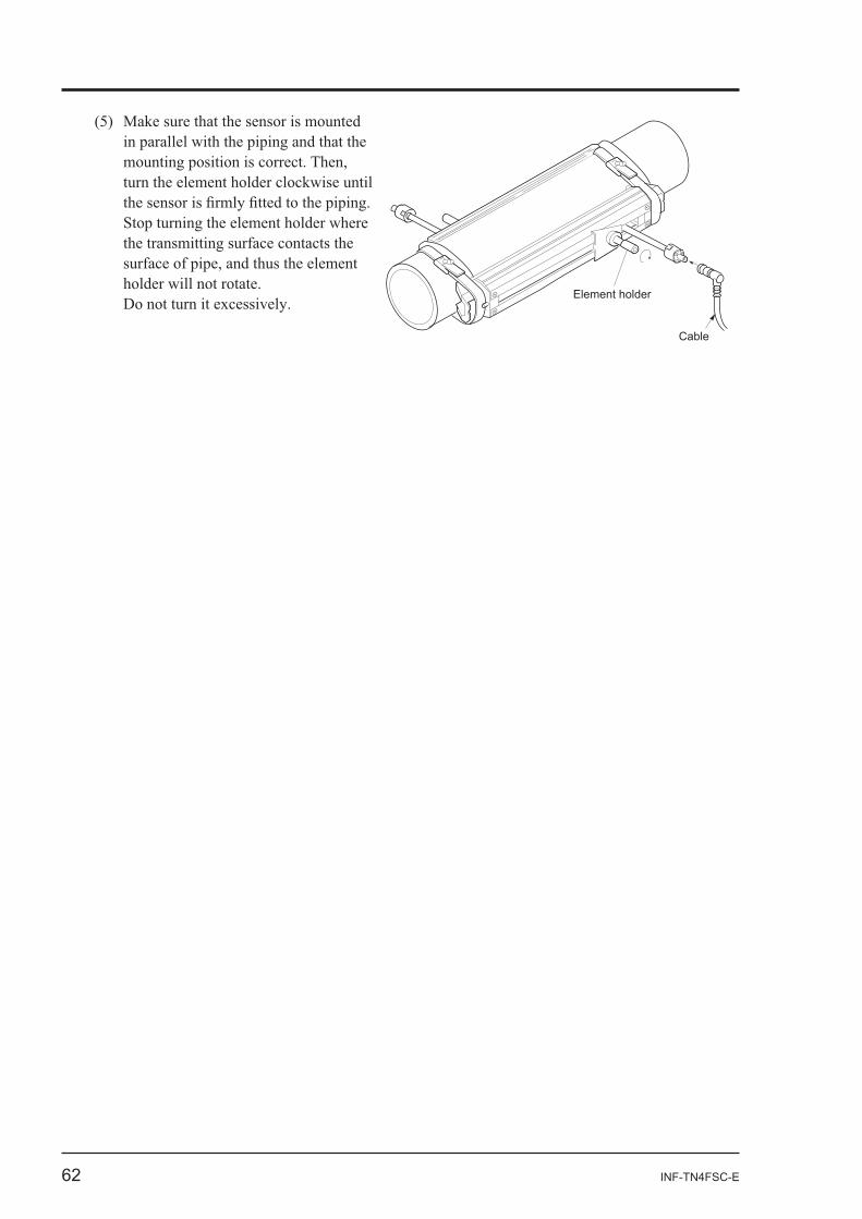
62 INF-TN4FSC-E
Element holder
Cable
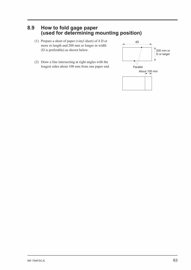
INF-TN4FSC-E 63
4D
Parallel
200 mm or D or larger
About 100 mm
64 INF-TN4FSC-E
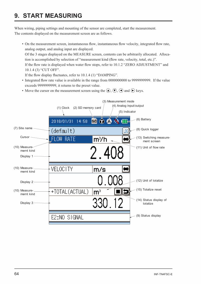
9. START MEASURING
-
and
(1) Clock
(7) Site name
Display 1
Cursor
Display 2
Display 3
(10) Measure- mernt kind
(10) Measure- mernt kind
(10) Measure- mernt kind
(2) SD memory card
(6) Battery
(4) Analog input/output
(5) Indicator
(8) Quick logger
(13) Switching measure- ment screen
(15) Totalize reset
(9) Status display
(14) Status display of totalize
(12) Unit of totalize
(11) Unit of flow rate
(3) Measurement mode
INF-TN4FSC-E 65
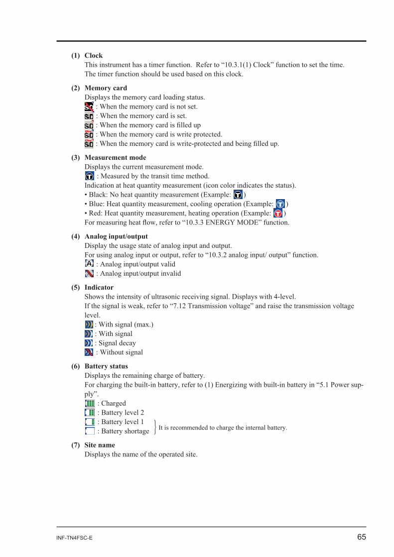
(1) Clock
(2) Memory card
(3) Measurement mode
))
)
(5) Indicator
-
(7) Site name
66 INF-TN4FSC-E
: Cannot be started
(9) Status display is indicated at the
-
-
ENT
the or ENT
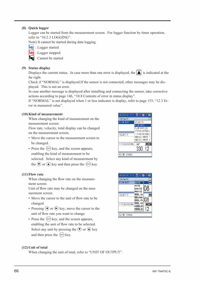
(11) Flow rate-
-
or
ENT
or and then press the ENT
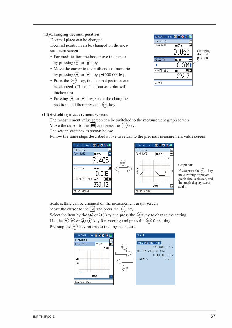
INF-TN4FSC-E 67
-
or
or ENT
or the ENT
Move the cursor to the and press the ENT
ENT
Move the cursor to the and press the ENT
or ENT
or ENT
ESC
ESC
ENT
position
If you press the ESCthe currently displayed
68 INF-TN4FSC-E
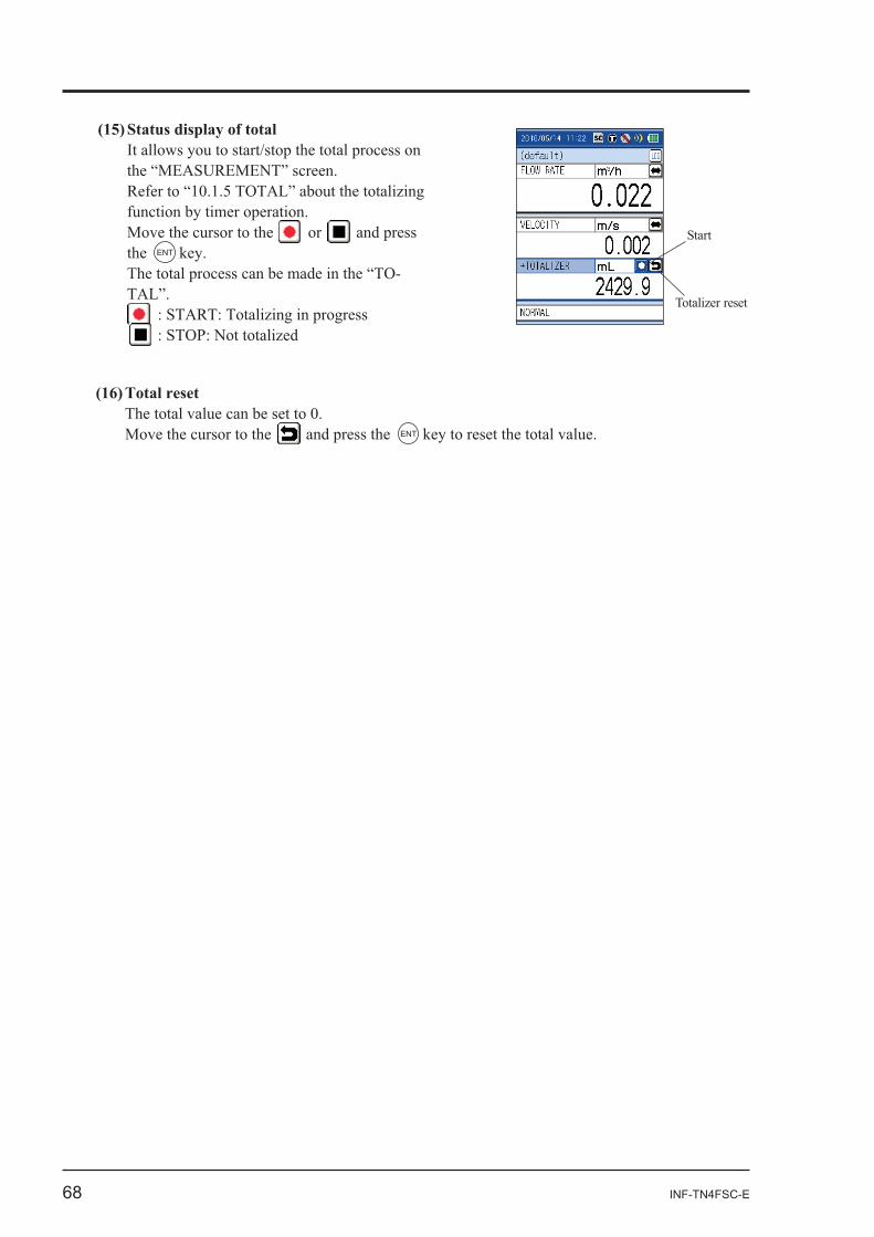
(15) Status display of totalIt allows you to start/stop the total process on
Move the cursor to the or and press the ENT
-
Move the cursor to the and press the ENT
Start
INF-TN4FSC-E 69
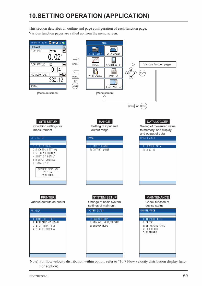
SITE SETUP RANGESetting of input andoutput range
Condition settings formeasurement
DATA LOGGER
PRINTERVarious outputs on printer
Saving of measured value to memory, and display and output of data
SYSTEM SETUP MAINTENANCECheck function of device status
Change of basic system settings of main unit
[Menu screen][Measure screen]
Various function pages
or
ENT
ESC
or
ESC
MENU
MENU
MENU
-
70 INF-TN4FSC-E
on the page
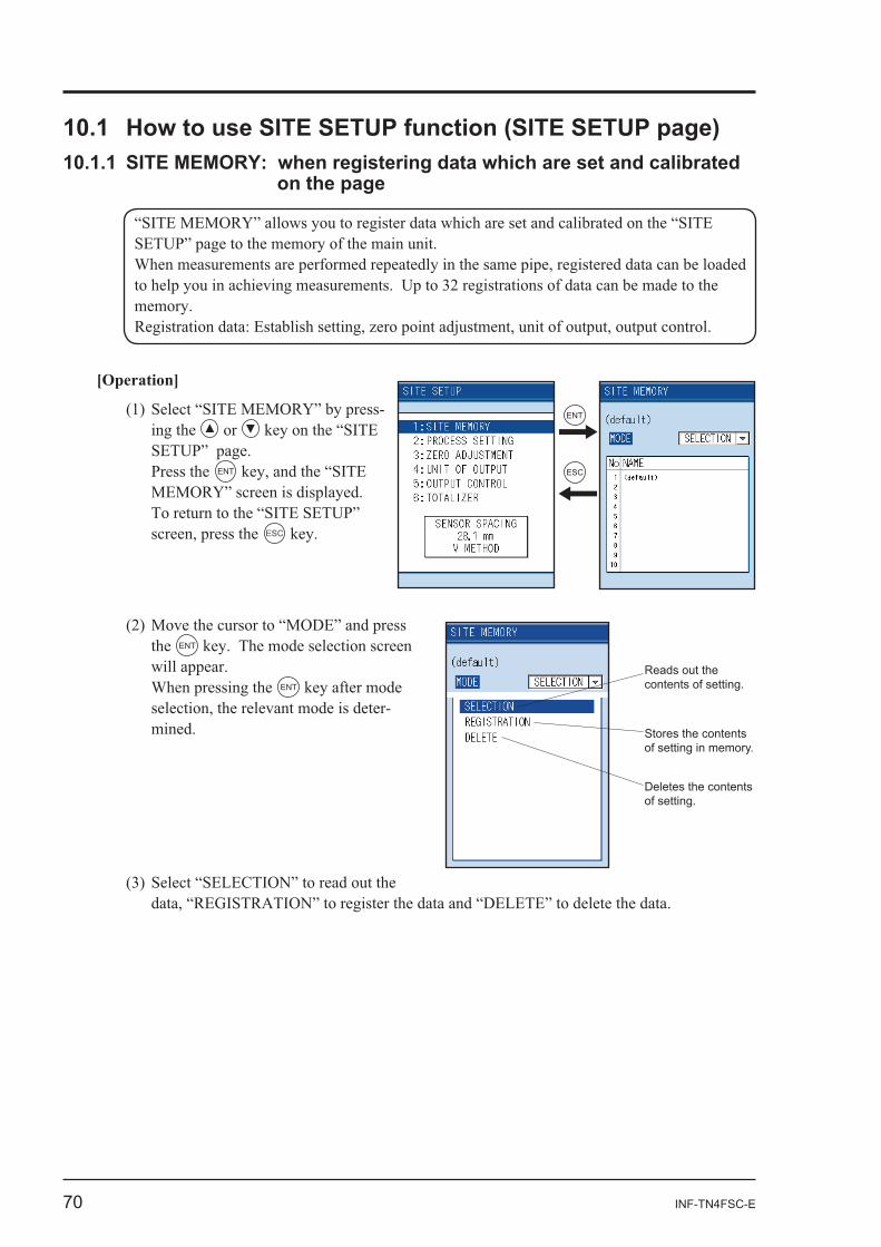
[Operation]
- or
Press the ENT
ESC
the ENT
ENT
-
Reads out the contents of setting.
Stores the contents of setting in memory.
Deletes the contents of setting.
ENT
ESC
INF-TN4FSC-E 71
ENT
ENT
ENT
ENT ENT
ENT
ENT ENT
ENT ENT
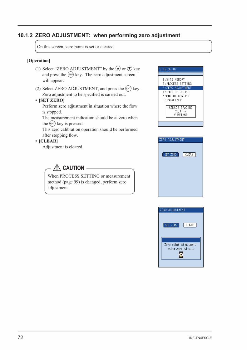
72 INF-TN4FSC-E
[Operation]
or and press the ENT
ENT
the ENT
CAUTION
INF-TN4FSC-E 73
3 3 3 3 3 3
3 3 3 3 3 3
3 3 3
3 3 3
Direction of selected unitDisplay Logger Printer
Flow rate unit : The unit selected by the unit of output is used.Flow rate total : The unit selected by measurement screen is used.Temperature
Thermal total
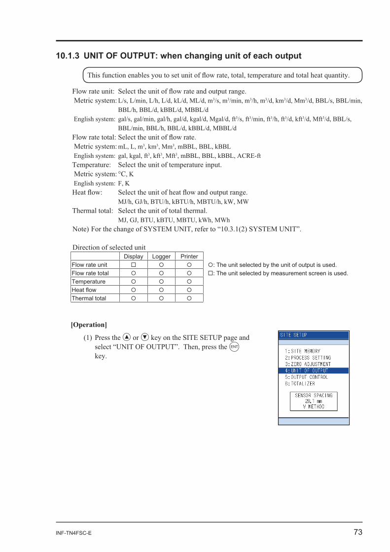
[Operation]
or ENT
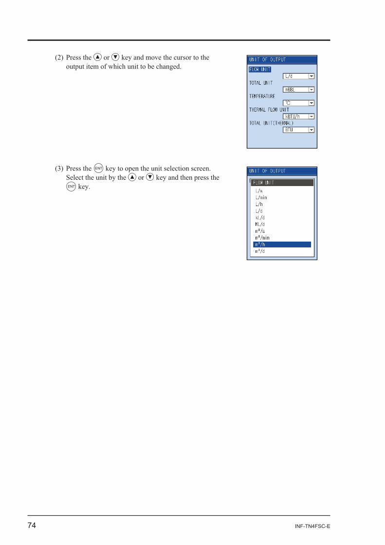
74 INF-TN4FSC-E
or
ENT
Select the unit by the or ENT
INF-TN4FSC-E 75
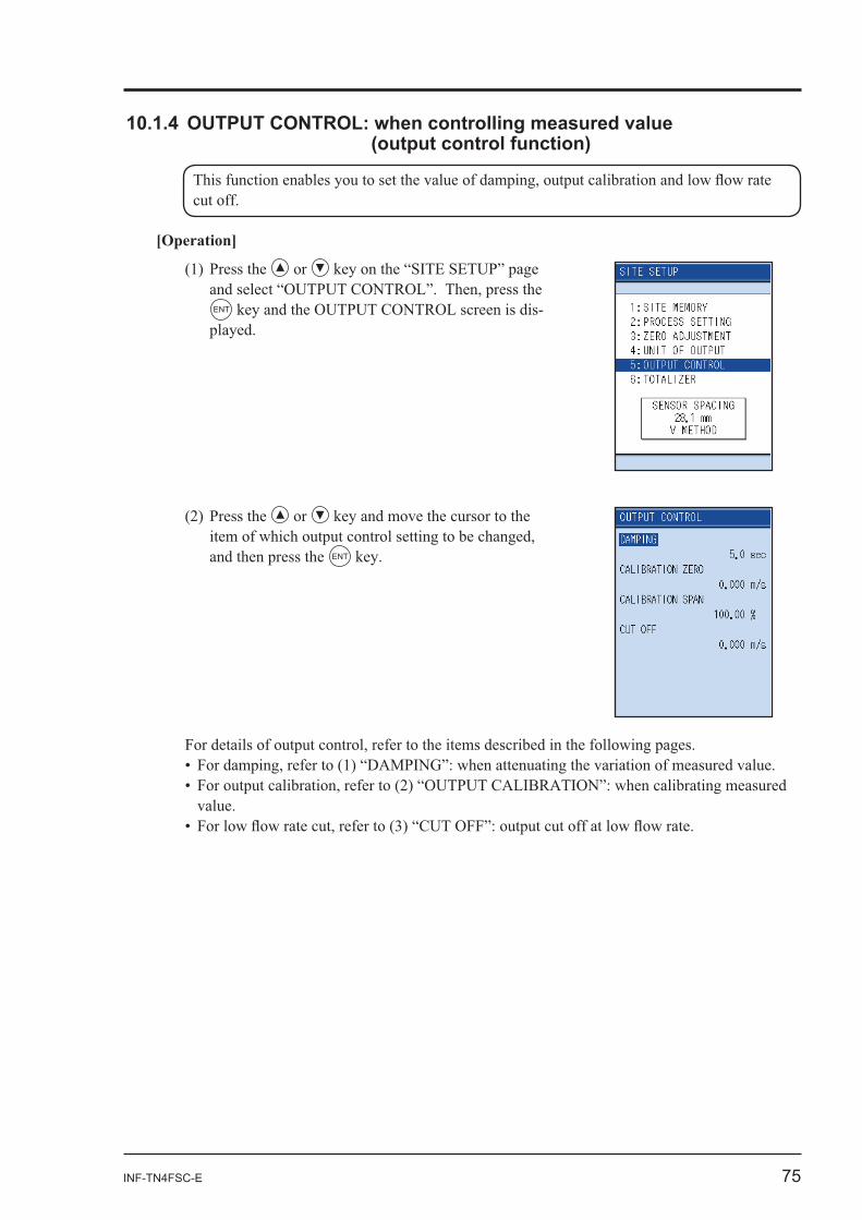
[Operation]
or
ENT -
or
and then press the ENT
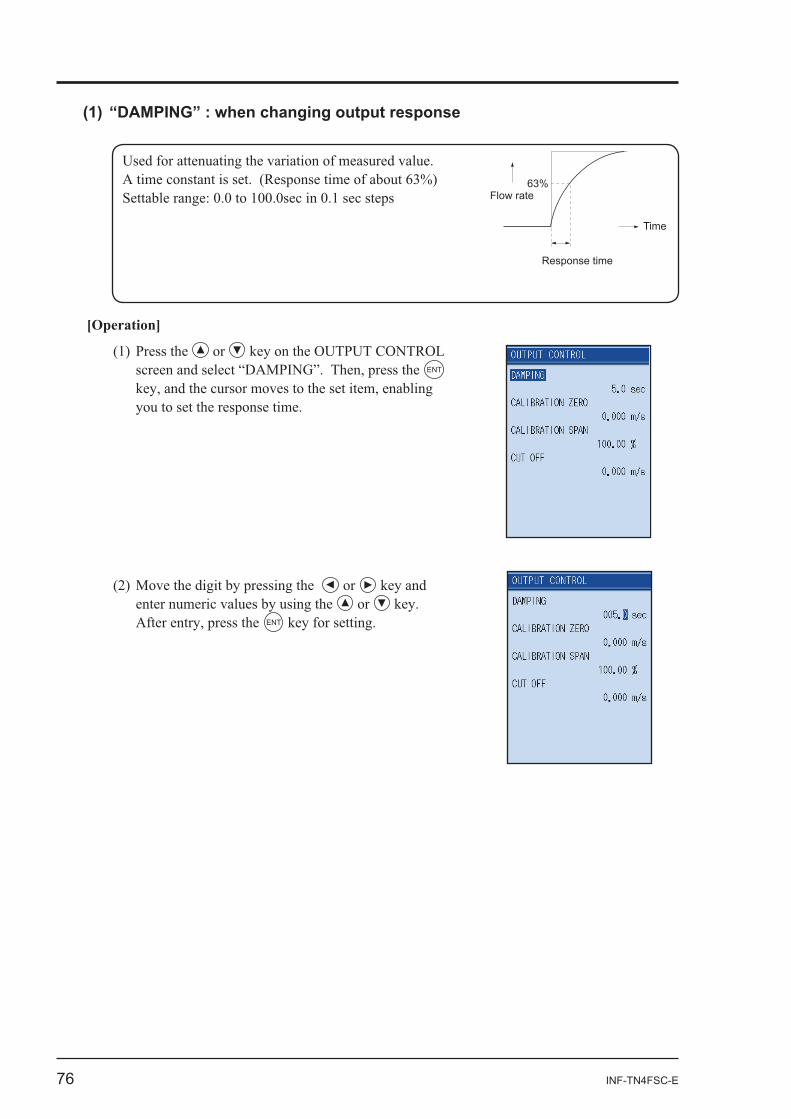
76 INF-TN4FSC-E
63%
Time
Response time
Flow rate
[Operation]
or ENT
or or
ENT
INF-TN4FSC-E 77
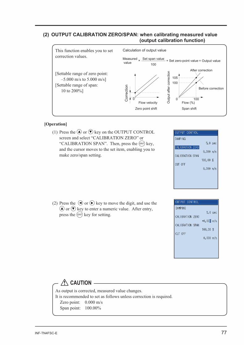
This function enables you to set
[Operation]
or
ENT
or or
press the ENT
0Cor
rect
ion
0 100
100
Calculation of output value
After correction
Before correction
Flow (%)Flow velocity
105
Zero point shift Span shift
Measured value = Output valueSet span value
100+ Set zero-point value
Out
put a
fter c
orre
ctio
n
×
CAUTION
78 INF-TN4FSC-E
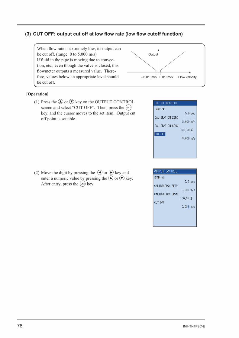
0.010m/s Flow velocity- 0.010m/s
Output
-
-
[Operation]
or ENT
or or
ENT
INF-TN4FSC-E 79
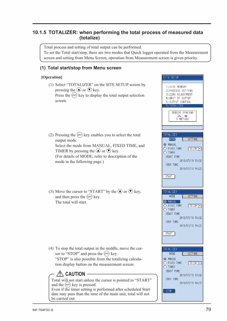
[Operation]
or Press the ENT
or and then press the ENT
ENT
or
-ENT
-
and the ENT
CAUTION
80 INF-TN4FSC-E
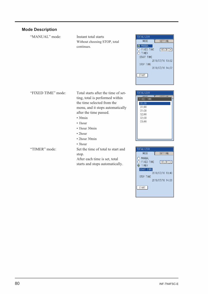
Mode DescriptionInstant total starts
-
INF-TN4FSC-E 81
the or ENT
the or Press the ENT
-
-
The total continues until the burnout
82 INF-TN4FSC-E
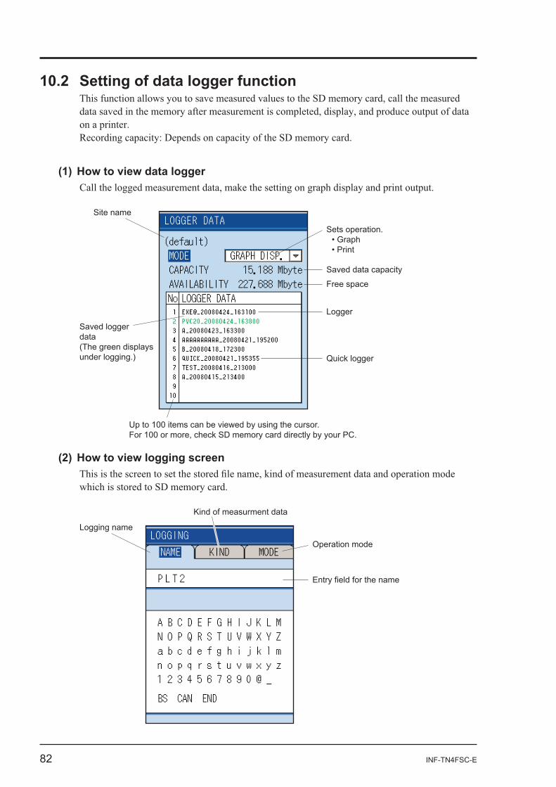
Saved loggerdata(The green displays under logging.)
Site name
Up to 100 items can be viewed by using the cursor.For 100 or more, check SD memory card directly by your PC.
Sets operation.
Saved data capacity
Free space
Logger
Quick logger
Logging name
Kind of measurment data
Operation mode
Entry field for the name
INF-TN4FSC-E 83
-
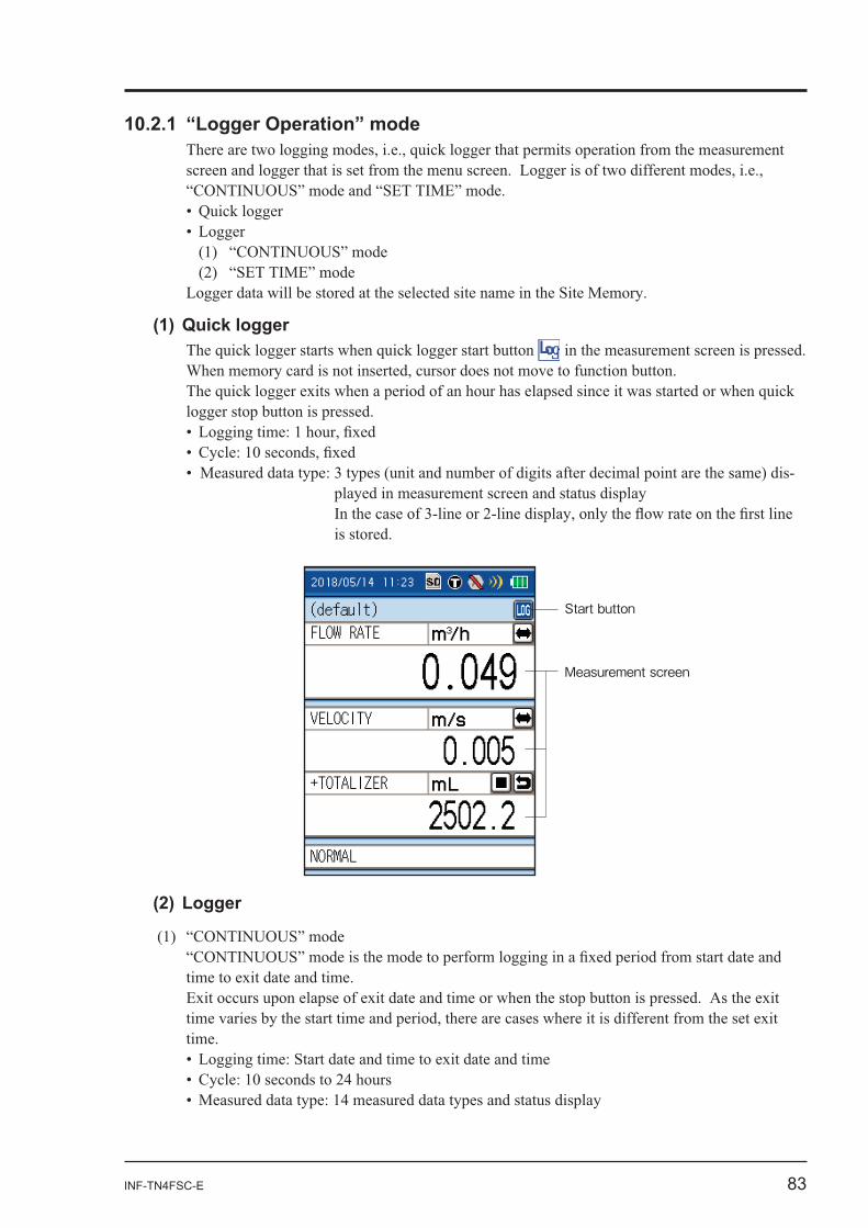
Start button
Measurement screen

84 INF-TN4FSC-E
9/1 9/2 9/3 9/4 9/5 9/6 9/7 9/8 : PM9:00 : AM4:00
: Logging
9/1 9/2 9/3 9/4 9/5 9/6 9/7 9/8 : 21:00 : 04:00
: Logging
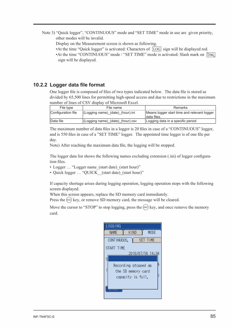
INF-TN4FSC-E 85
LOGLOG
File type File name Remarks(Logging name)_(date)_(hour).ini Means logger start time and relevant logger
(Logging name)_(date)_(hour).csv
-
Press the ESC
ENT
86 INF-TN4FSC-E
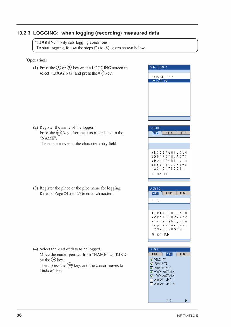
[Operation]
or ENT
Press the ENT
by the ENT
INF-TN4FSC-E 87
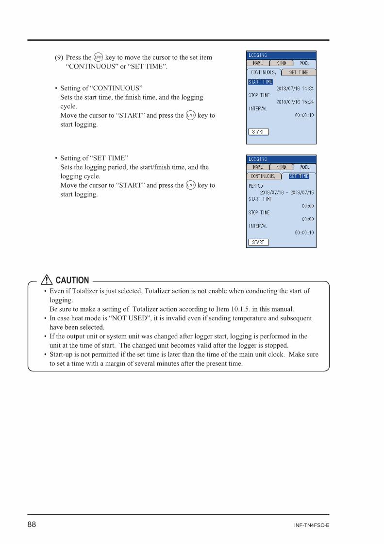
or the ENT
Press the
ESC
ENT -
CAUTION
88 INF-TN4FSC-E
ENT
ENT
ENT
CAUTION
INF-TN4FSC-E 89
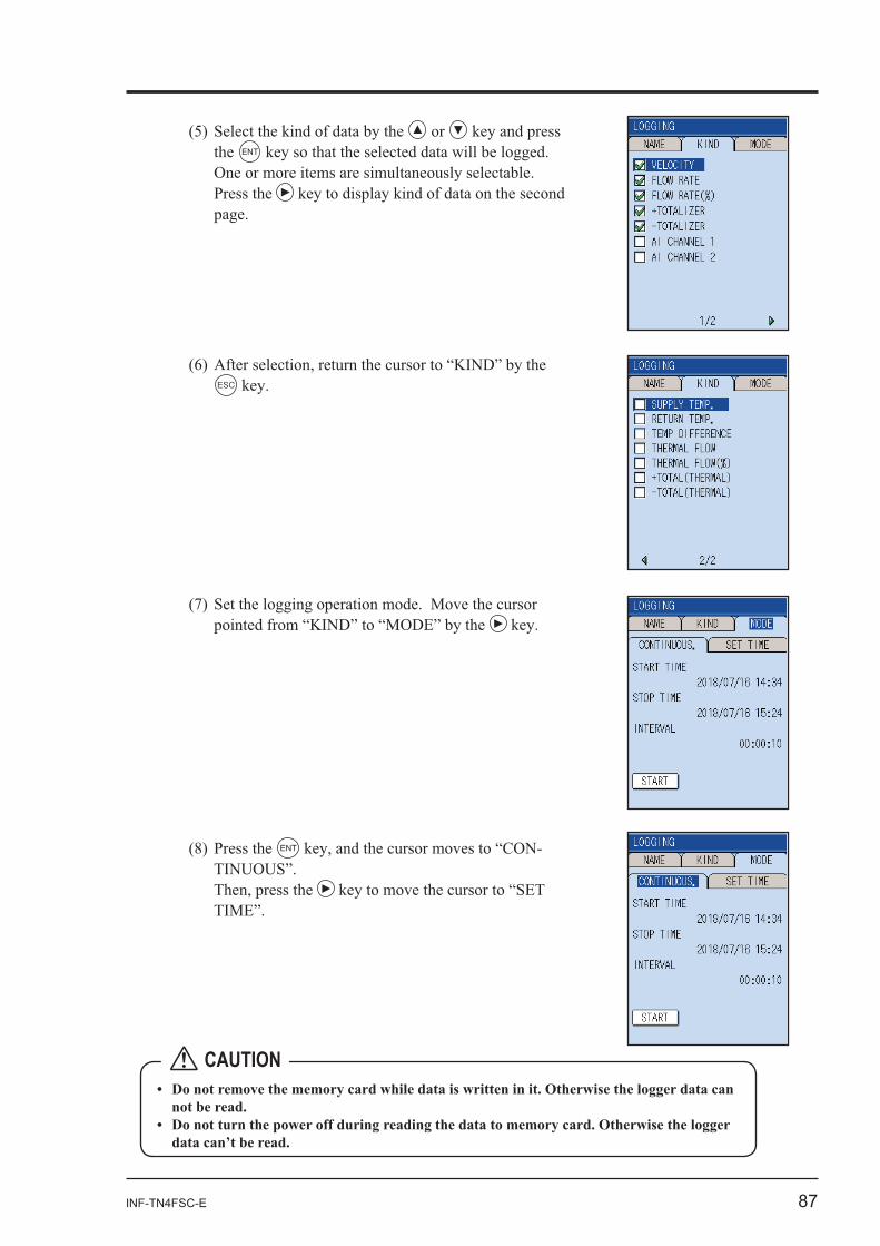
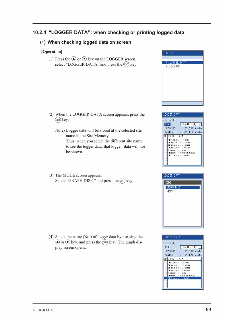
[Operation]
or ENT
ENT
ENT
or ENT -
90 INF-TN4FSC-E
ENT
or
or or
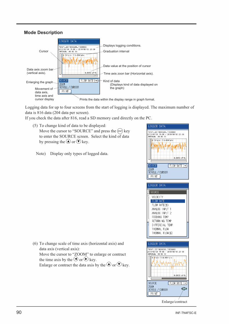
Displays logging conditions.
Graduation intervalCursor
Data axis zoom bar (vertical axis).
Enlarging the graph
Movement of data axis, time axis and cursor display
Data value at the position of cursor
Time axis zoon bar (Horizontal axis).
Kind of data (Displays kind of data displayed on the graph)
Prints the data within the display range in graph format.
Mode Description
INF-TN4FSC-E 91
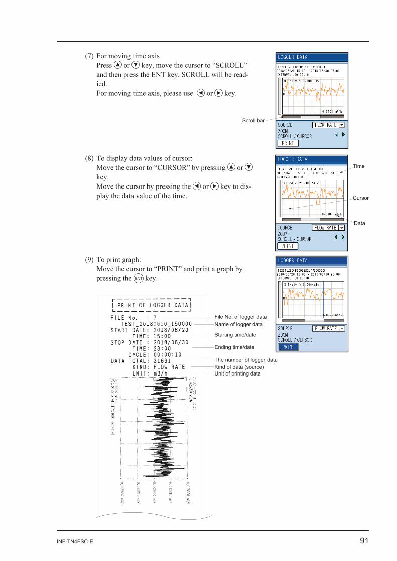
ENT
File No. of logger dataName of logger data
Starting time/date
Ending time/date
The number of logger dataKind of data (source)Unit of printing data
Cursor
Time
Data
Press or -
or
or
or -
Scroll bar
92 INF-TN4FSC-E
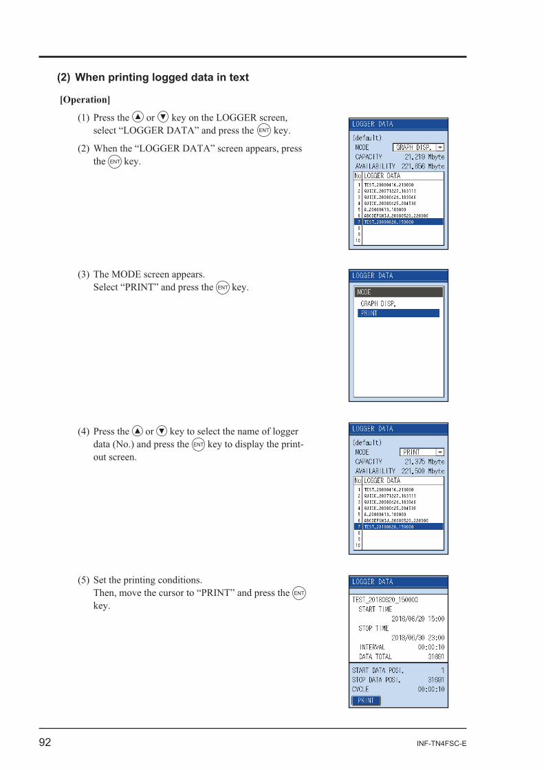
[Operation]
or ENT
the ENT
ENT
or ENT -
ENT
INF-TN4FSC-E 93
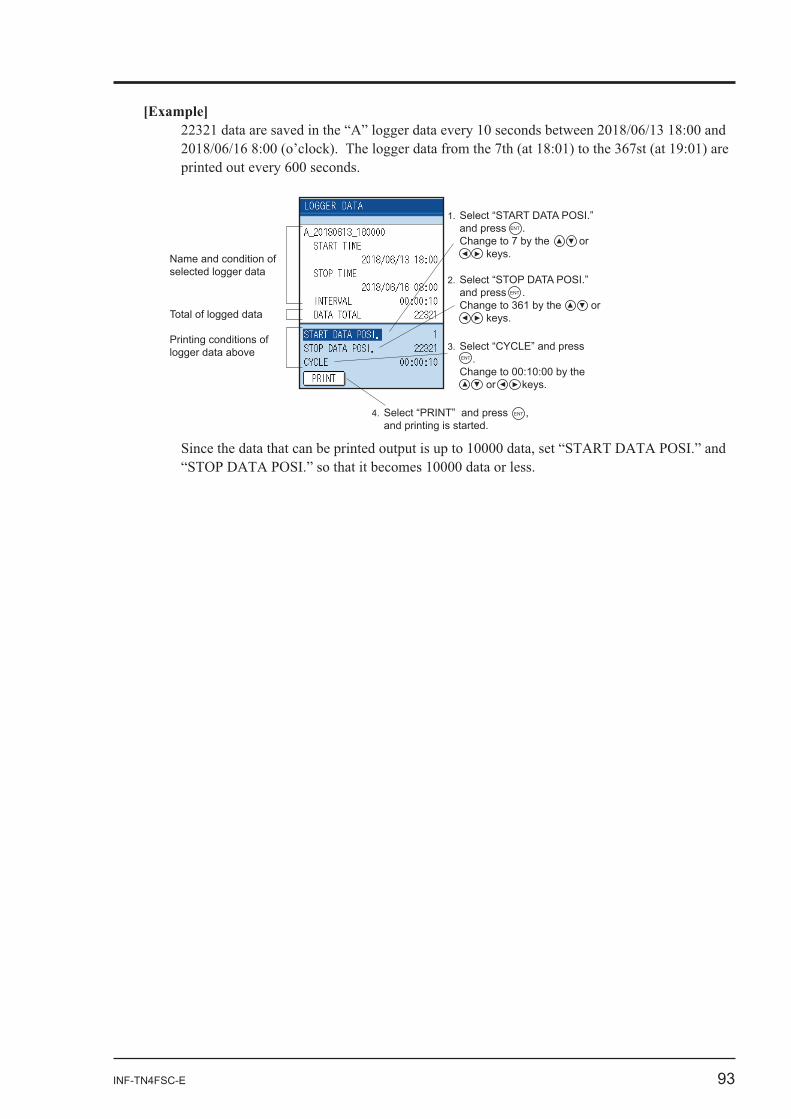
1. Select “START DATA POSI.” and press . Change to 7 by the or keys.
ENT
2. Select “STOP DATA POSI.” and press . Change to 361 by the or keys.
ENT
3. Select “CYCLE” and press . Change to 00:10:00 by the or keys.
ENT
4. Select “PRINT” and press , and printing is started.
ENT
Name and condition of selected logger data
Total of logged data
Printing conditions of logger data above
94 INF-TN4FSC-E
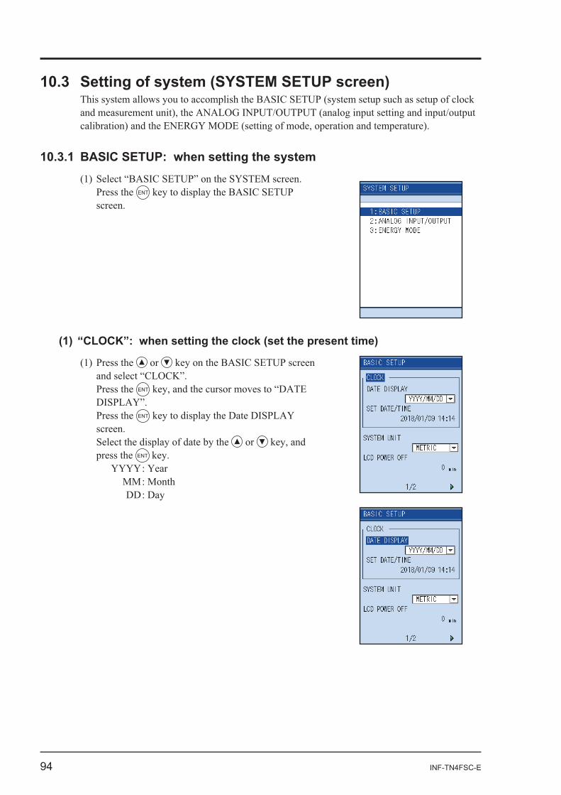
or
Press the ENT
Press the ENT
Select the display of date by the or press the ENT
YYYY : Year MM : Month DD : Day
Press the ENT
INF-TN4FSC-E 95
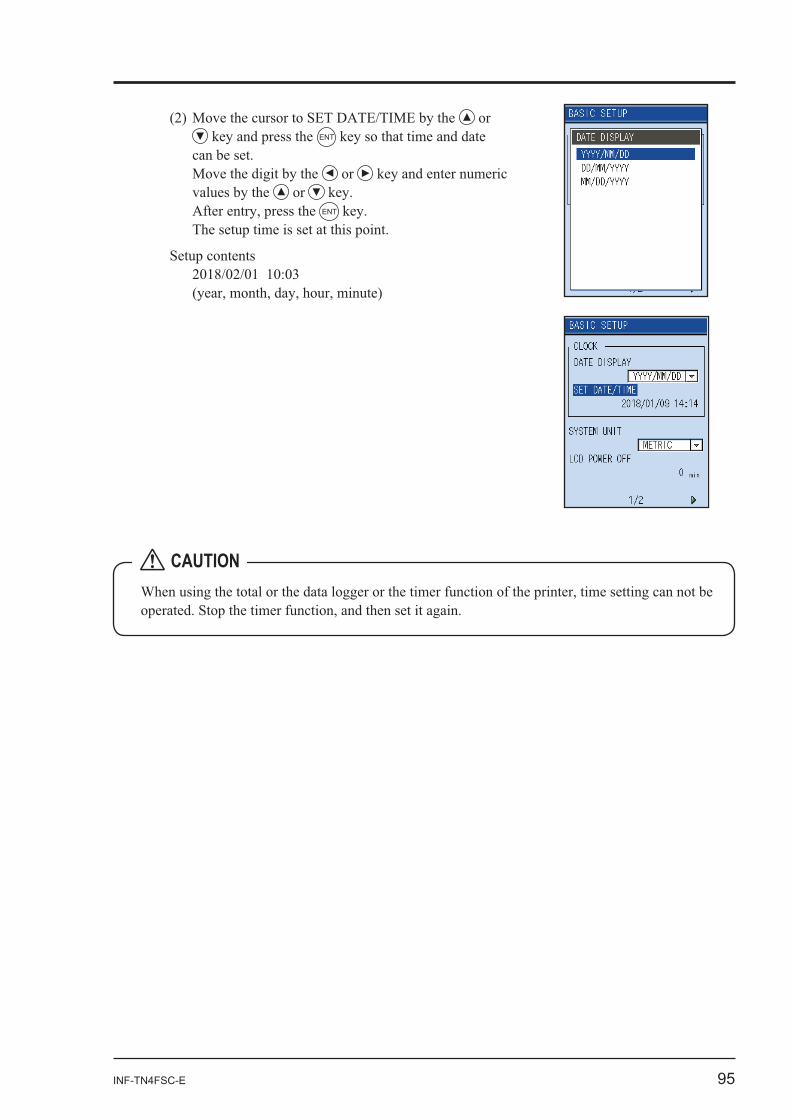
or ENT
or values by the or
ENT
Setup contents
CAUTION
96 INF-TN4FSC-E
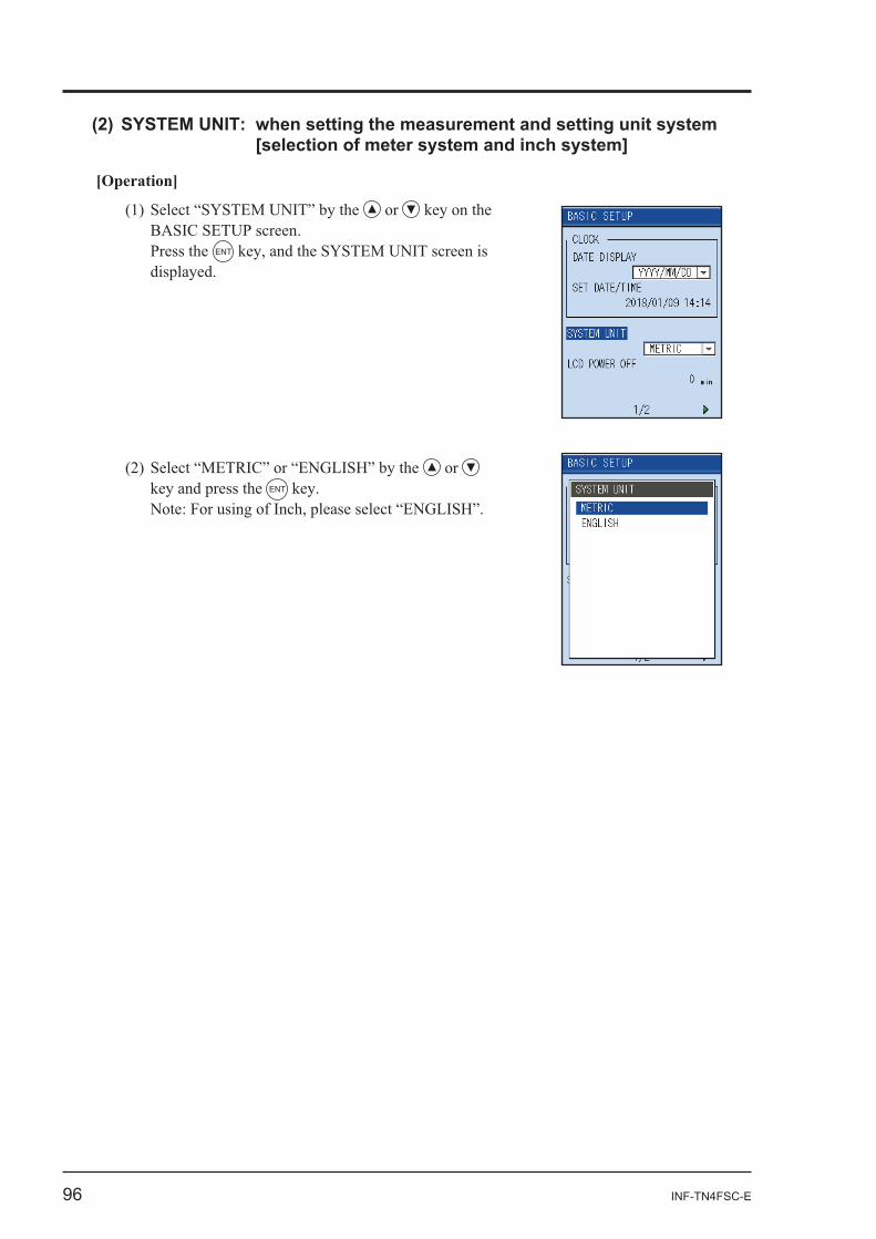
[Operation]
or
Press the ENT
or ENT
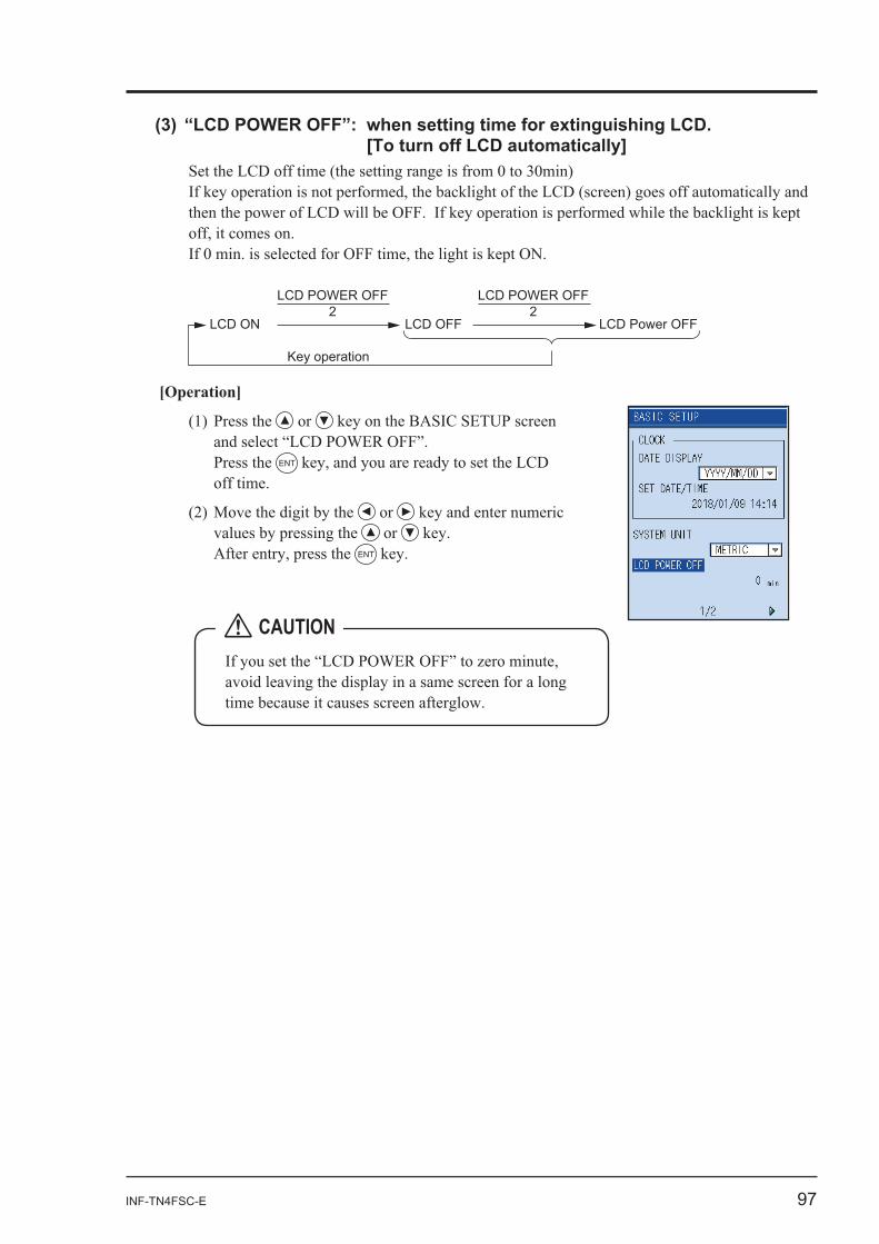
INF-TN4FSC-E 97
LCD ON
LCD POWER OFF2
Key operation
LCD POWER OFF2
LCD OFF LCD Power OFF
[Operation]
or
Press the ENT
or or
ENT
CAUTION
98 INF-TN4FSC-E
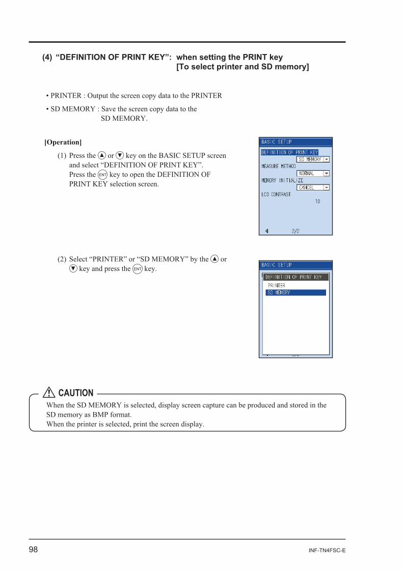
or ENT
[Operation]
or
Press the ENT
CAUTION
INF-TN4FSC-E 99
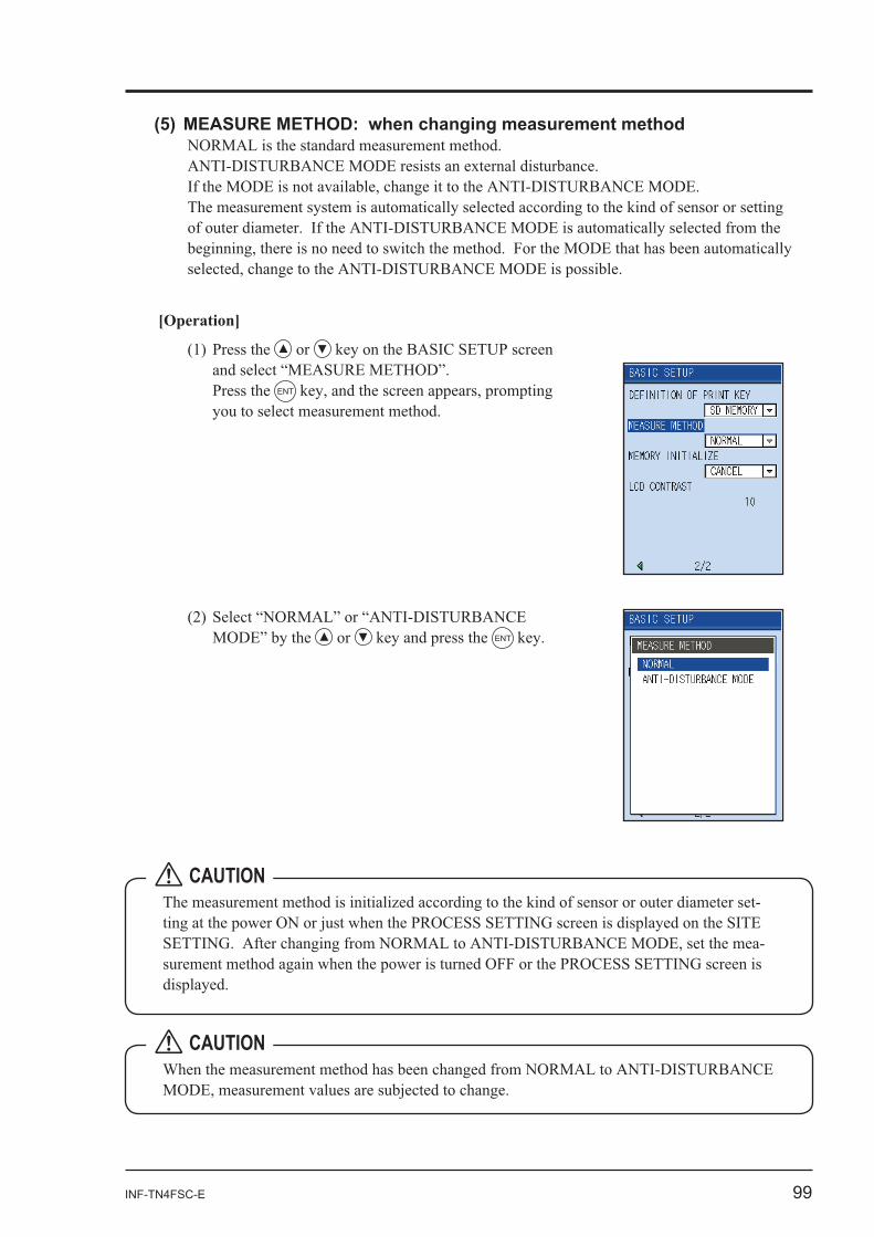
[Operation]
or
Press the ENT
-
-
CAUTION
or ENT
CAUTION
100 INF-TN4FSC-E
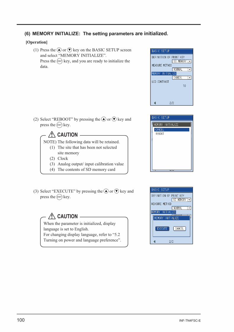
[Operation]
or
Press the ENT
CAUTION
or press the ENT
CAUTION
or press the ENT
INF-TN4FSC-E 101
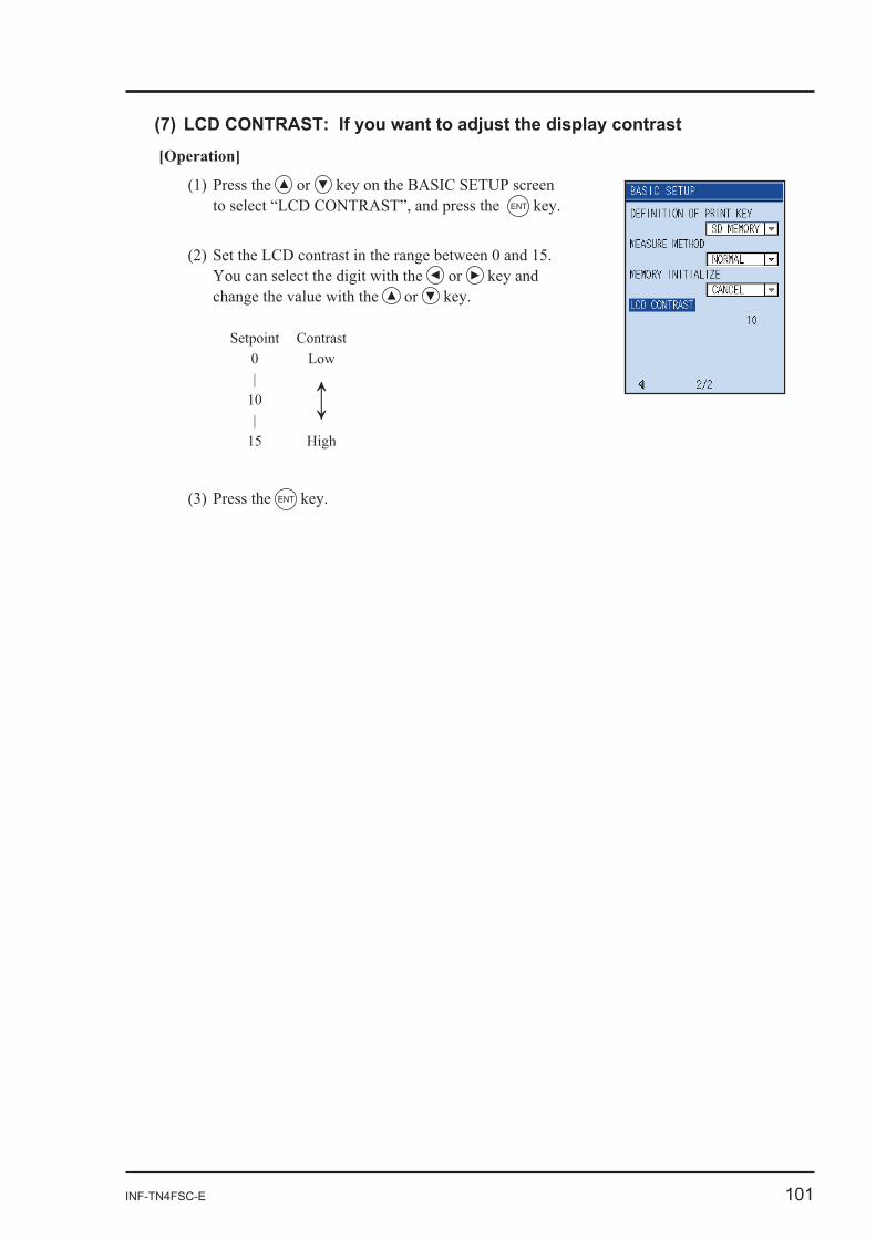
[Operation]
or ENT
or and or
Setpoint Contrast
ENT
102 INF-TN4FSC-E
-
Press the ENT
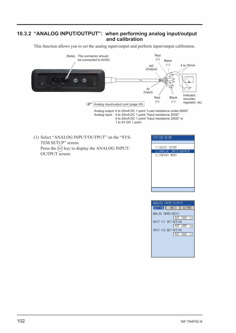
and calibration
AI ch2
AOAI ch1
Red(+)
Red(+)
Black
Black
4 to 20mAAO(Output)
Indicator, recorder,regulator, etc.
(Note) The connector should be connected to AI/AO.
1 to 5V DC 1 point
Analog input/output cord (page 20)
-+AI(Input)
INF-TN4FSC-E 103
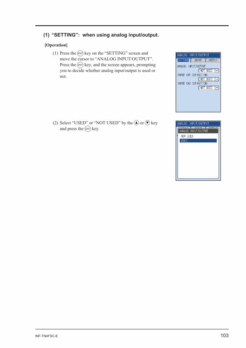
[Operation]
ENT
Press the ENT
or and press the ENT
104 INF-TN4FSC-E
ENT
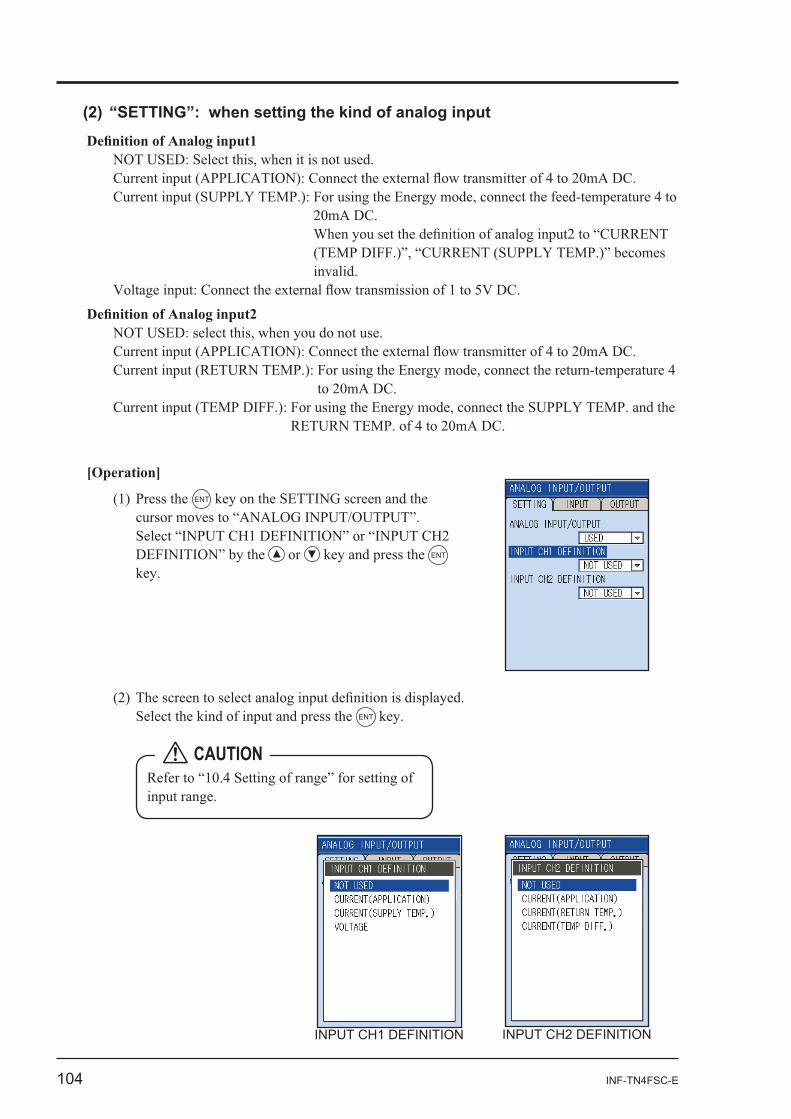
[Operation]
ENT
or ENT
INPUT CH1 DEFINITION INPUT CH2 DEFINITION
CAUTION
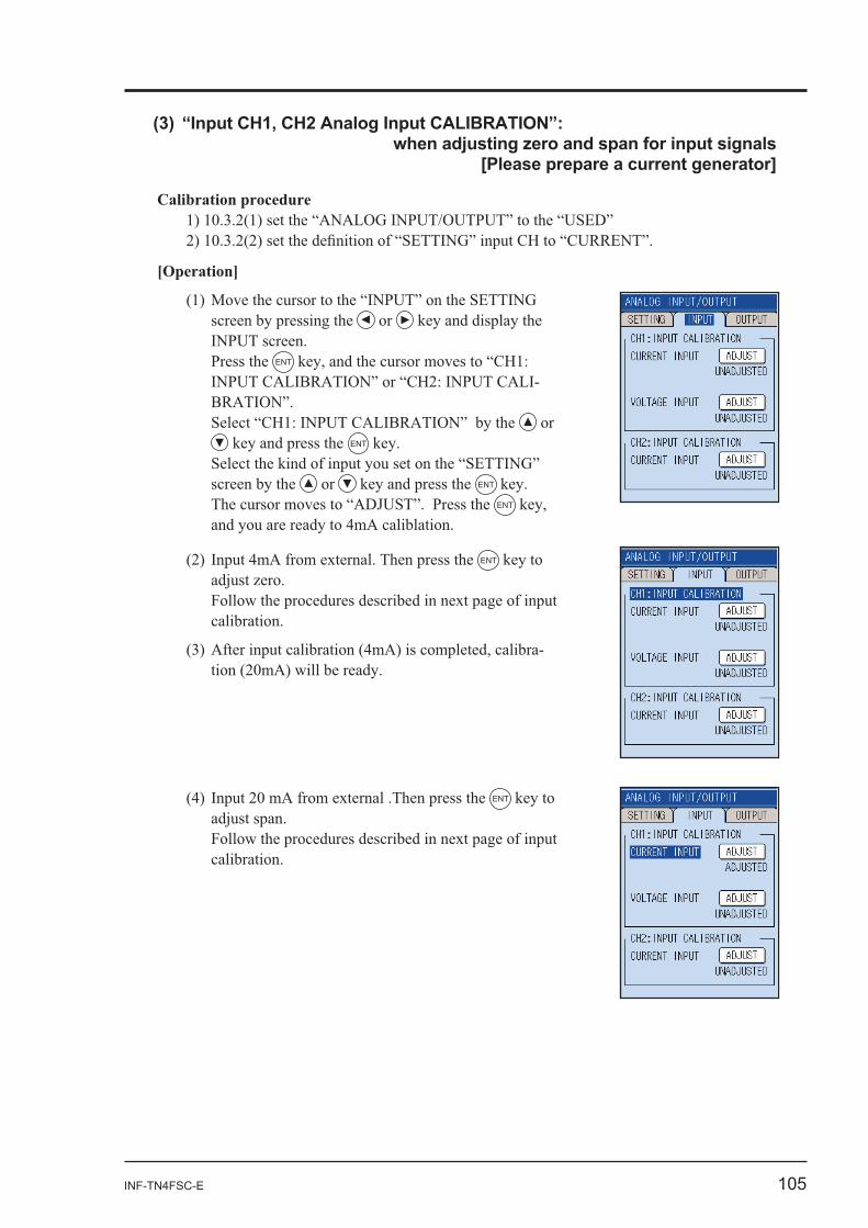
INF-TN4FSC-E 105
ENT
Calibration procedure
[Operation]
or
Press the ENT
-
or ENT
screen by the or ENT
ENT
ENT
-
106 INF-TN4FSC-E
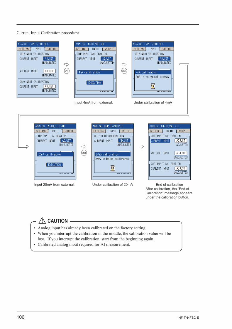
Current Input Caribration procedure
ENT
Input 4mA from external. Under calibration of 4mA
ENT
ENT
Input 20mA from external. Under calibration of 20mA End of calibrationAfter calibration, the “End of Calibration” message appears under the calibration button.
CAUTION
INF-TN4FSC-E 107
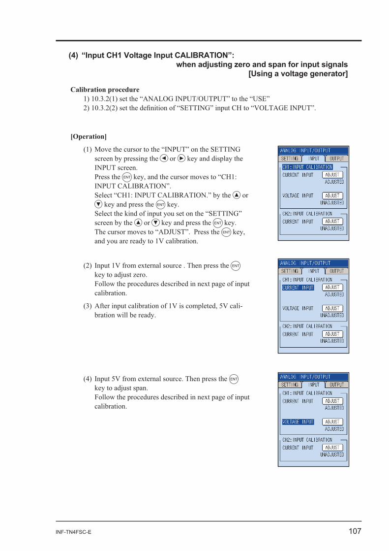
Calibration procedure
[Operation]
or
Press the ENT
or ENT
screen by the or ENT
ENT
ENT
-
ENT
108 INF-TN4FSC-E
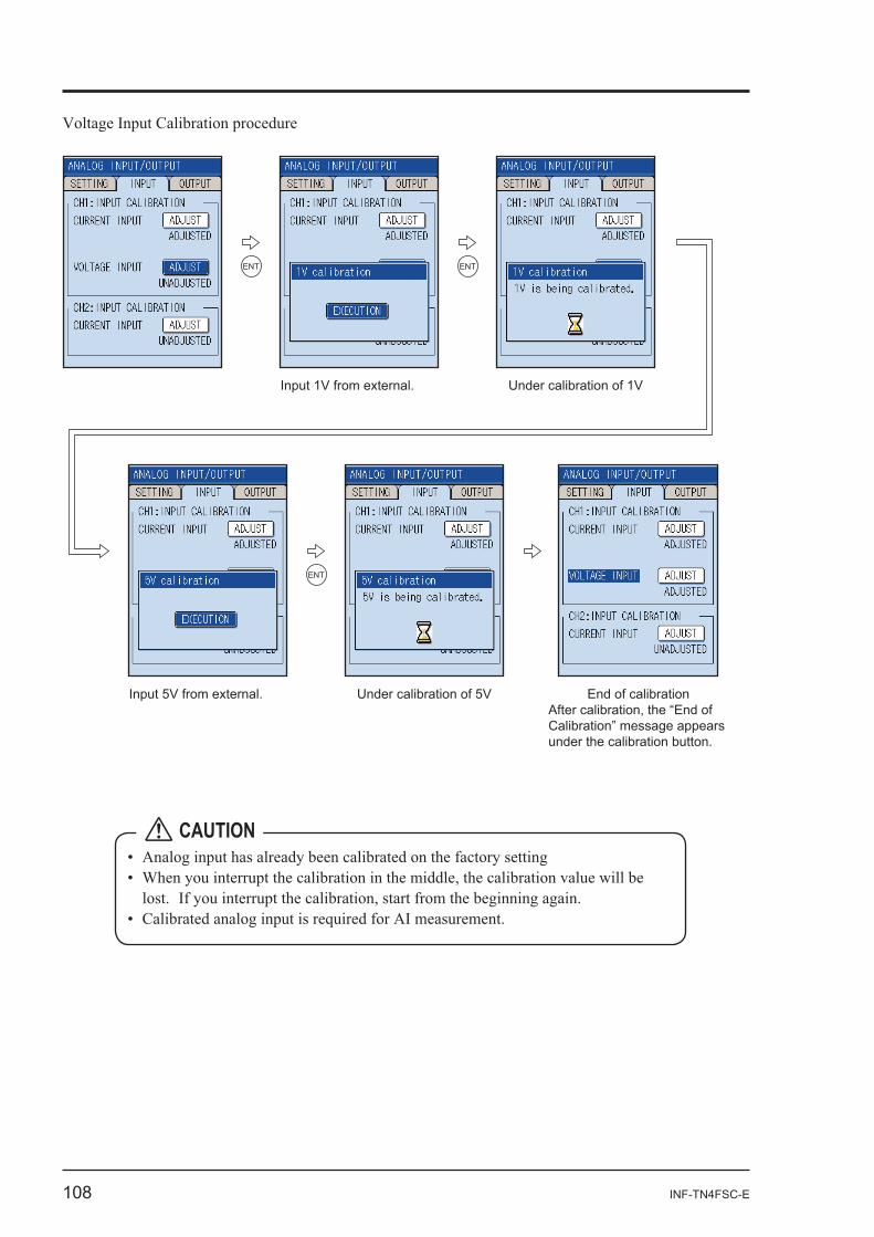
ENT
Input 1V from external. Under calibration of 1V
ENT
ENT
Input 5V from external. Under calibration of 5V End of calibrationAfter calibration, the “End of Calibration” message appears under the calibration button.
CAUTION
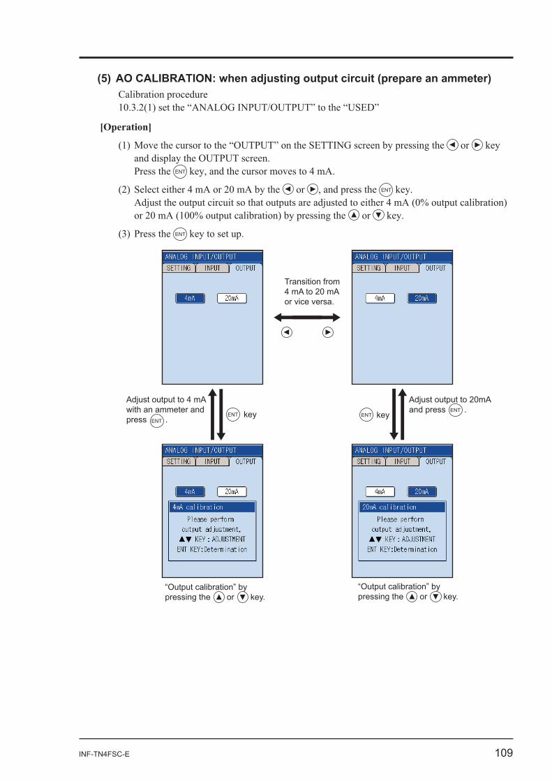
INF-TN4FSC-E 109
Calibration procedure
[Operation]
or
Press the ENT
or ENT
or
ENT
ENT
Adjust output to 20mAand press .
ENT
Adjust output to 4 mA with an ammeter and press .
ENT ENT
“Output calibration” by pressing the or key.
“Output calibration” by pressing the or key.
key key
Transition from 4 mA to 20 mA or vice versa.
110 INF-TN4FSC-E
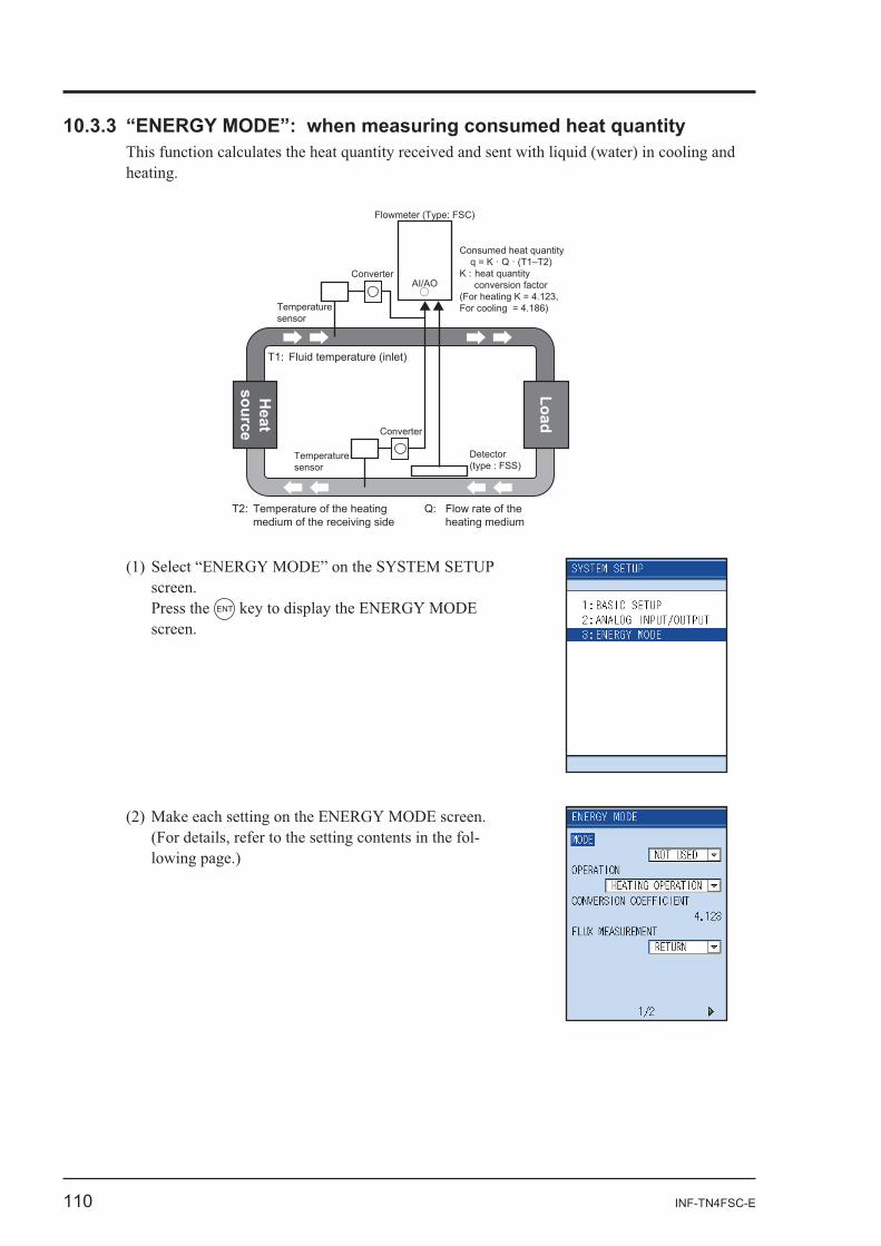
Press the ENTH
eatsource
Load
Detector(type : FSS)
Converter
Converter
Q: Flow rate of the heating medium
T2: Temperature of the heating medium of the receiving side
T1: Fluid temperature (inlet)
Flowmeter (Type: FSC)
Consumed heat quantity q = K · Q · (T1–T2)K : heat quantity conversion factor(For heating K = 4.123,For cooling = 4.186)Temperature
sensor
Temperaturesensor
AI/AO
-
INF-TN4FSC-E 111
-
-
-
112 INF-TN4FSC-E
-
INF-TN4FSC-E 113
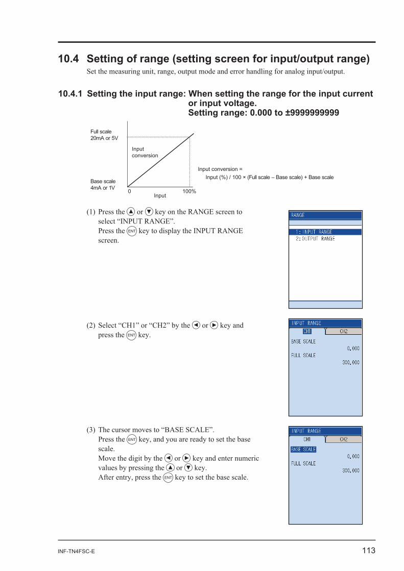
or input voltage.
0 100%Input
Input conversion
Full scale20mA or 5V
Base scale4mA or 1V
Input conversion = Input (%) / 100 × (Full scale – Base scale) + Base scale
or
Press the ENT
or press the ENT
Press the ENT
or or
ENT
114 INF-TN4FSC-E
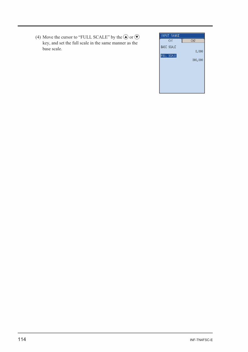
or
INF-TN4FSC-E 115
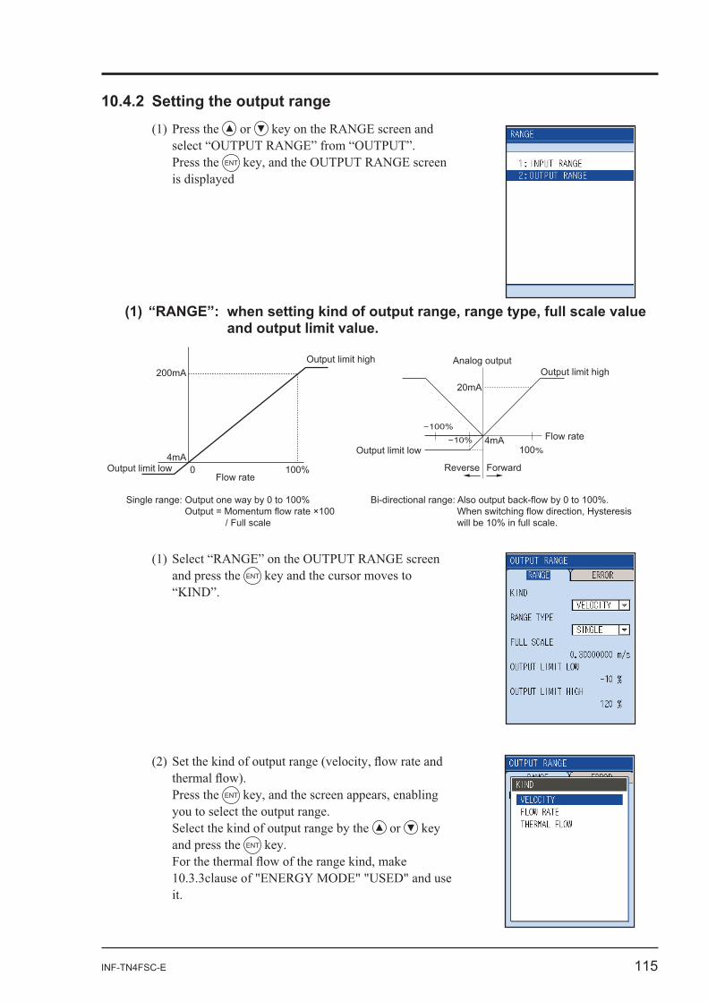
or
Press the ENT
is displayed
and press the ENT
Press the ENT
or
and press the ENT
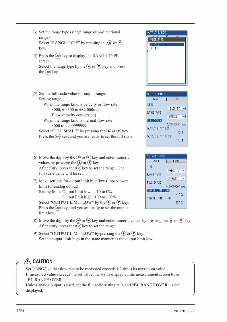
100%
Flow rate
ForwardReverse
Analog output
20mA
4mA
Output limit highOutput limit high
Output limit low
0 100%
200mA
4mAOutput limit low
Flow rate
Single range: Output one way by 0 to 100%Output = Momentum flow rate ×100 / Full scale
Bi-directional range: Also output back-flow by 0 to 100%. When switching flow direction, Hysteresis will be 10% in full scale.
116 INF-TN4FSC-E
or or ENT
or Press the ENT
or or ENT
or
or
ENT
or the ENT
or Press the ENT
CAUTION
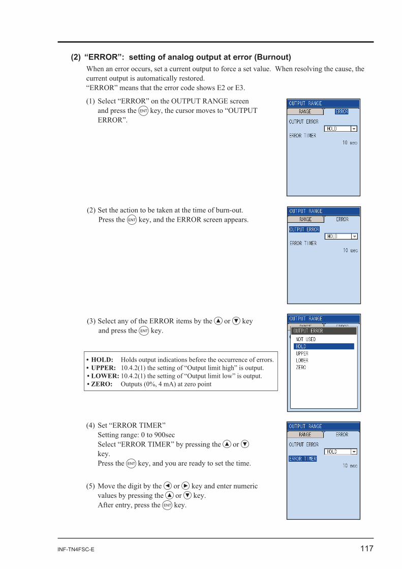
INF-TN4FSC-E 117
Press the ENT
or and press the ENT
and press the ENT
or
Press the ENT
or or
ENT
118 INF-TN4FSC-E
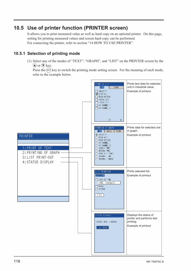
or Press the ENT
Prints text data for selected unit in industrial value.Example of printout
Prints data for selected unit in graph.Example of printout
Prints selected list.Example of printout
Displays the status of printer and performs test printing.Example of printout
INF-TN4FSC-E 119
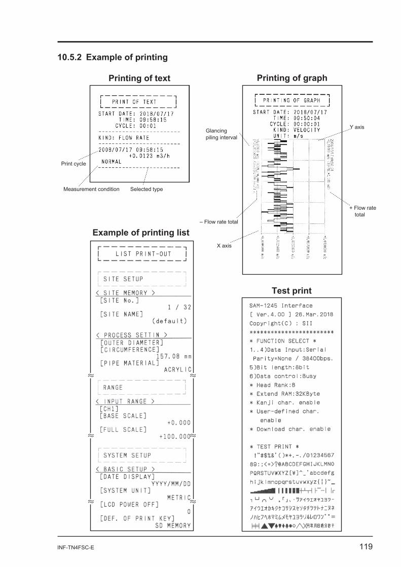
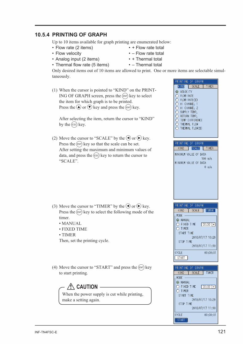
Printing of graph
Test print
Print cycle
Measurement condition Selected type
Glancing piling interval
– Flow rate total
X axis
Y axis
+ Flow rate total
120 INF-TN4FSC-E
or
Press the ENT
-
ENT
Press the or press the ENT
or
ESC
ENT
ENT
CAUTION
INF-TN4FSC-E 121
-
-ENT
Press the or ENT
by the ESC
or Press the ENT
ESC
or Press the ENT
ENT
CAUTION
122 INF-TN4FSC-E
ENT
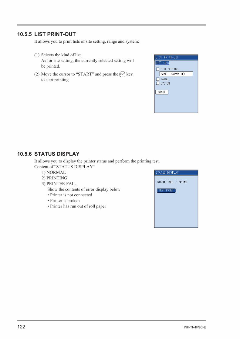
Show the contents of error display below
INF-TN4FSC-E 123
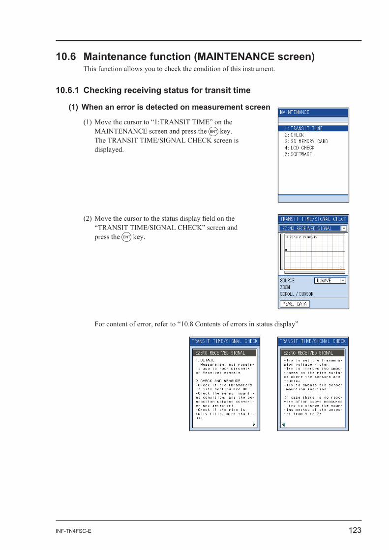
ENT
press the ENT
124 INF-TN4FSC-E
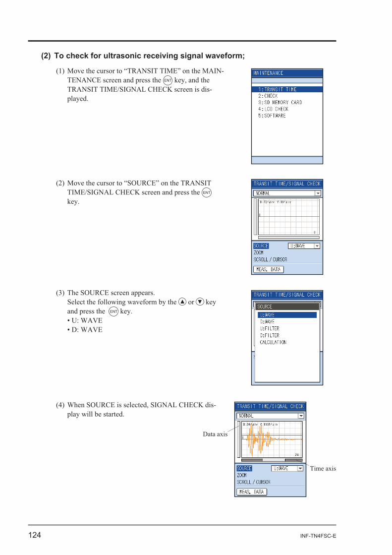
-ENT
-
ENT
-
or and press the ENT
INF-TN4FSC-E 125
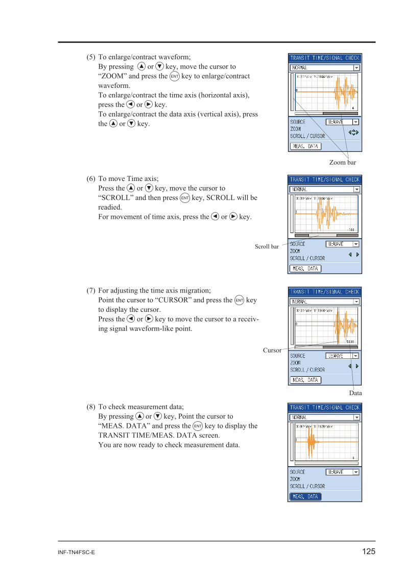
or ENT
press the or
the or
Press the or
ENT
or
ENT
Press the or -
or ENT
Scroll bar
Cursor
Data
126 INF-TN4FSC-E
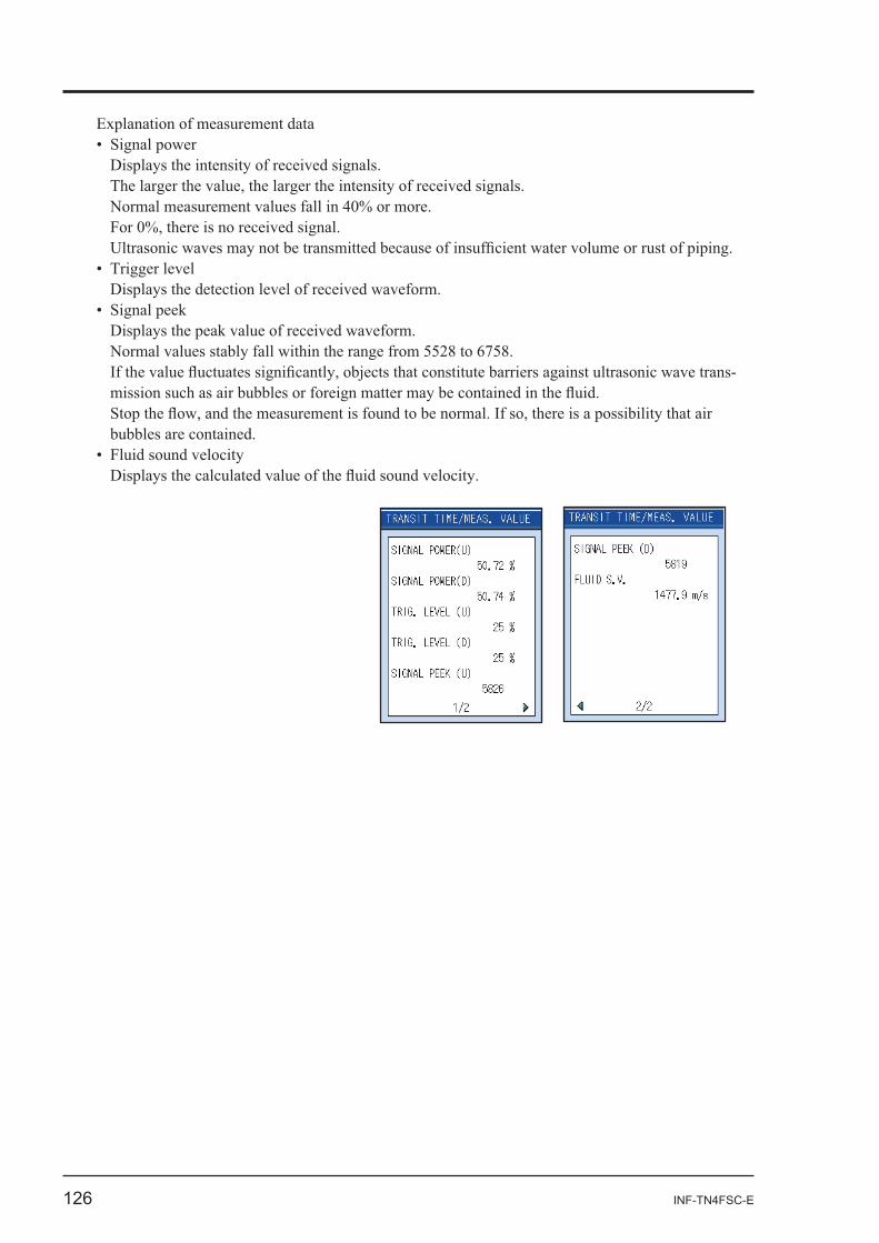
-
INF-TN4FSC-E 127
-
-
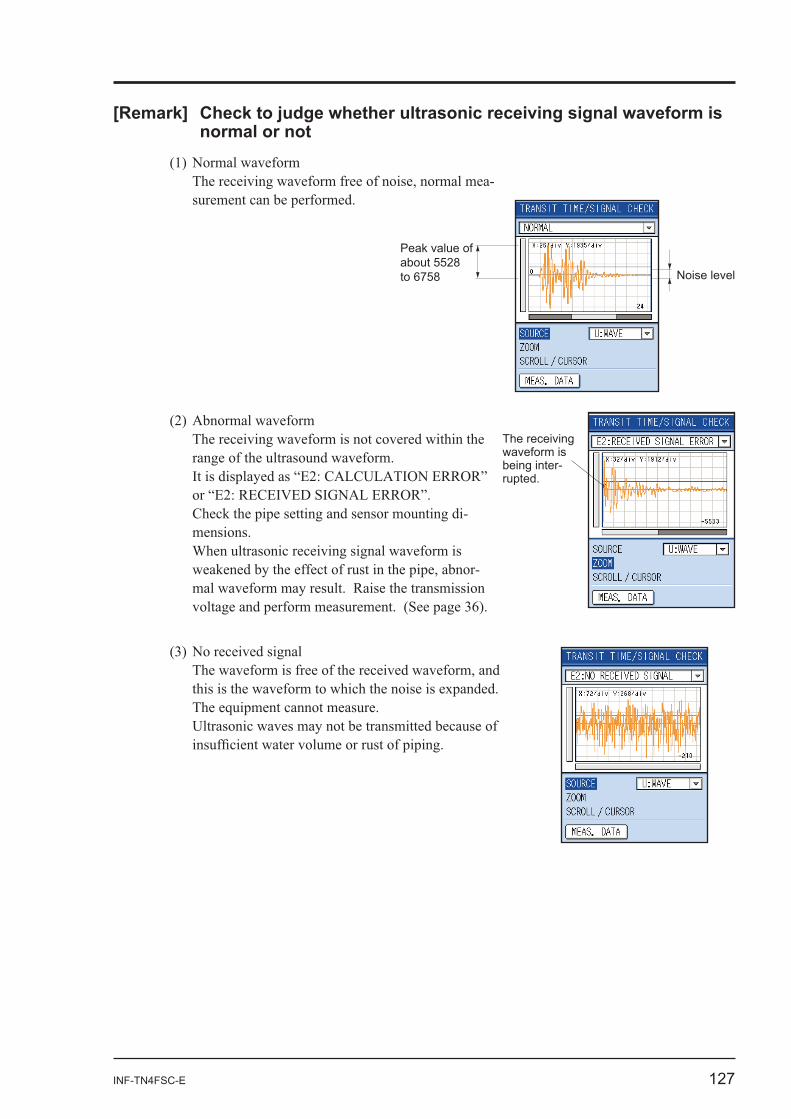
Peak value of about 5528 to 6758 Noise level
-
The receiving waveform is being inter-rupted.
128 INF-TN4FSC-E
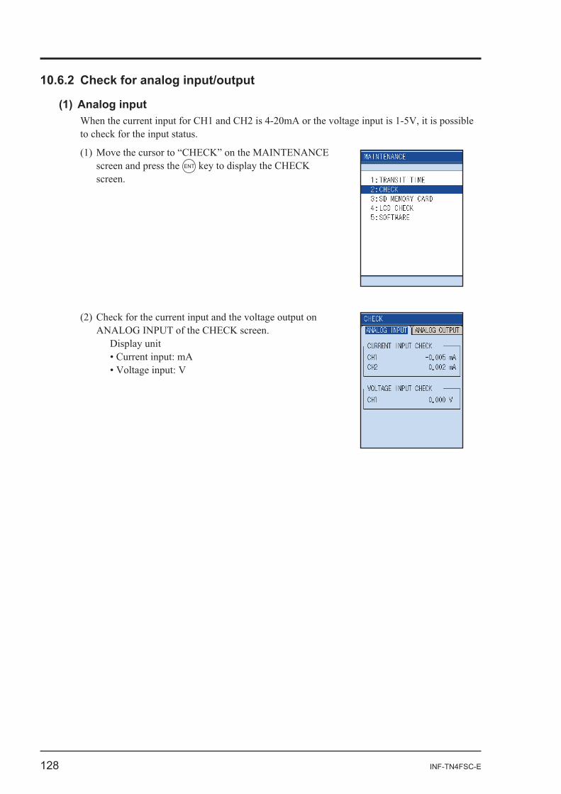
screen and press the ENT
Display unit
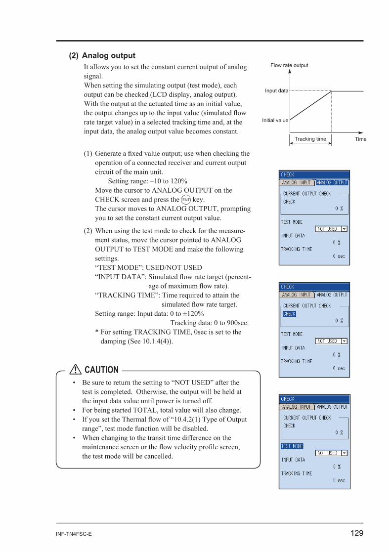
INF-TN4FSC-E 129
operation of a connected receiver and current output
ENT
-
-
Time
Initial value
Flow rate output
Tracking time
Input data
CAUTION
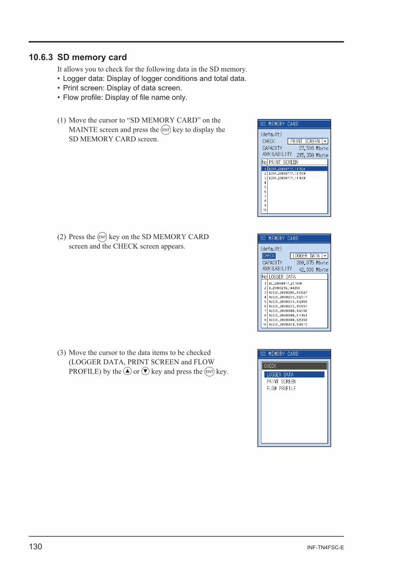
130 INF-TN4FSC-E
ENT
ENT
or ENT
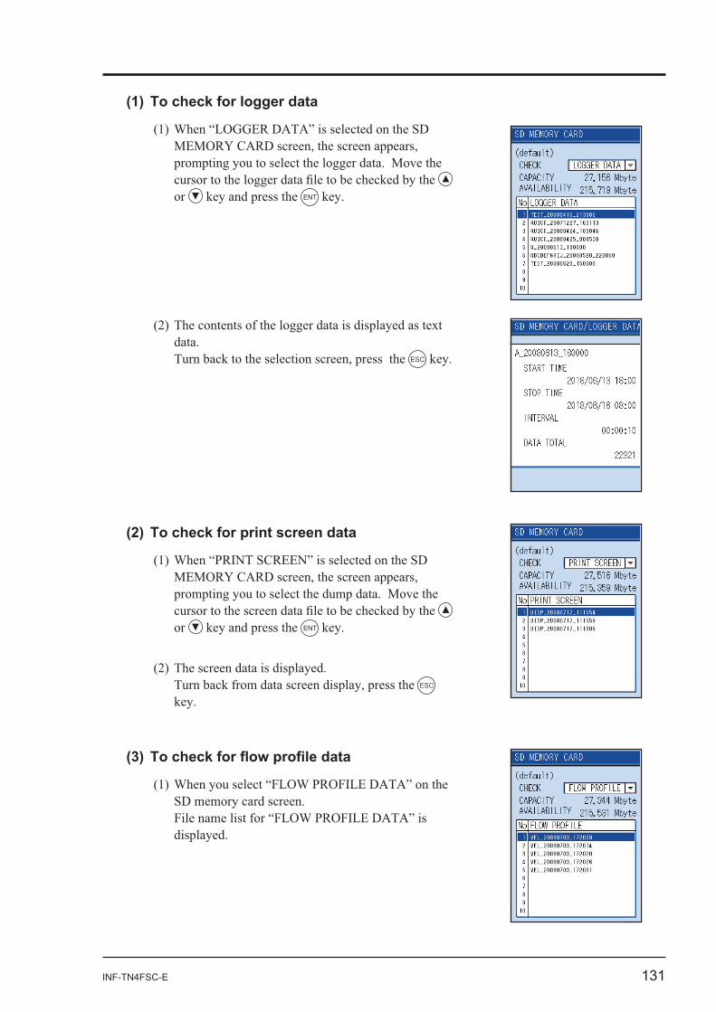
INF-TN4FSC-E 131
or ENT
ESC
or ENT
ESC
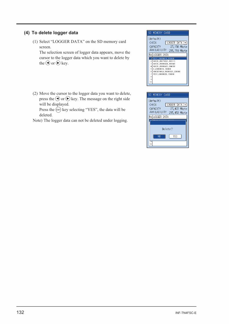
132 INF-TN4FSC-E
the or
press the or
Press the ENT
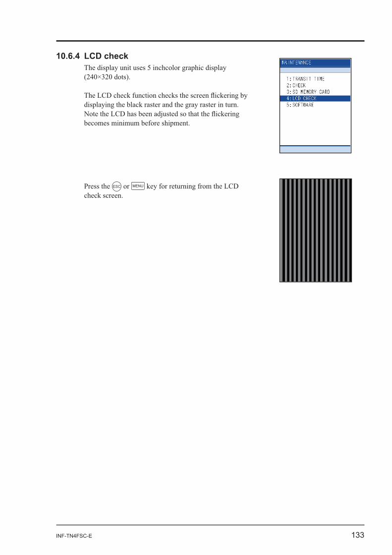
INF-TN4FSC-E 133
Press the ESC or MENU
134 INF-TN4FSC-E
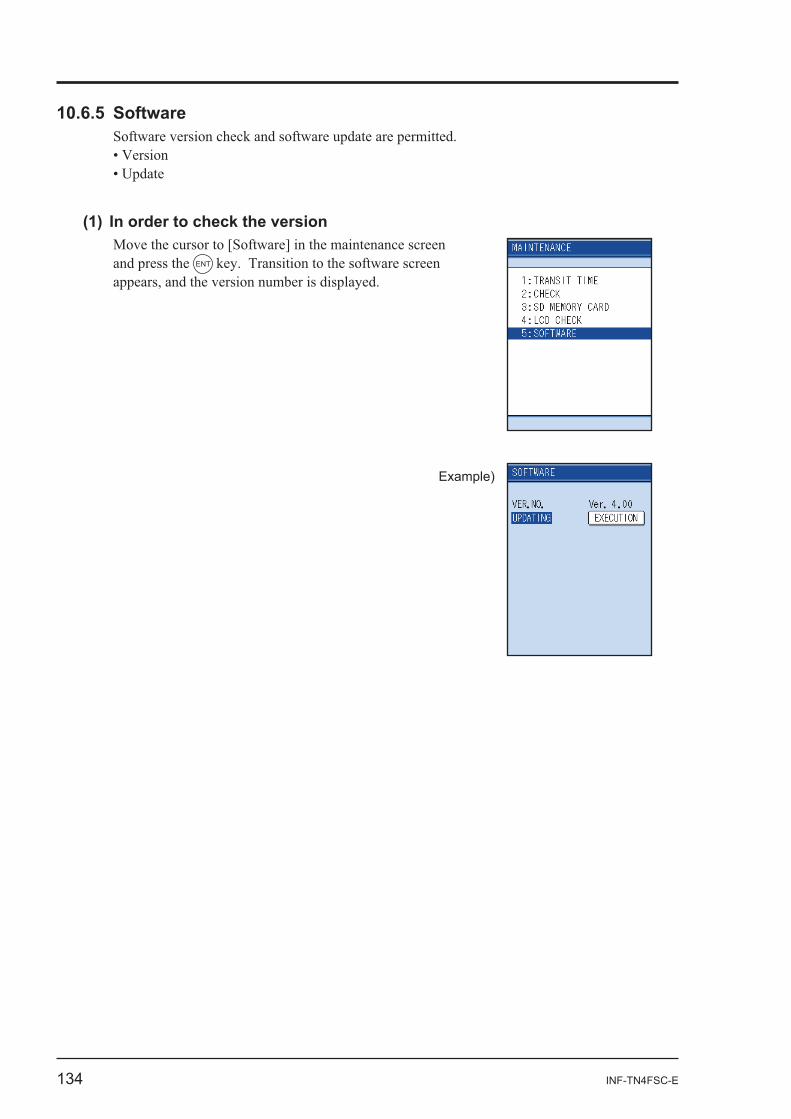
and press the ENT
Example)
INF-TN4FSC-E 135
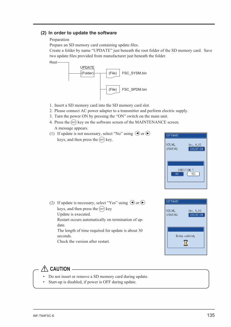
Preparation
Root
(Folder) UPDATE
(File) FSC_SYSM.bin
FSC_SPDM.bin(File)
ENT
or ENT
CAUTION
or ENT
-
136 INF-TN4FSC-E
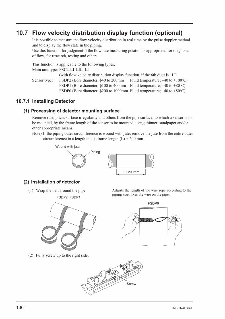
Main unit type: FSC -
Wound with jutePiping
L+200mm
FSDP2, FSDP1
FSDP0
Screw
INF-TN4FSC-E 137
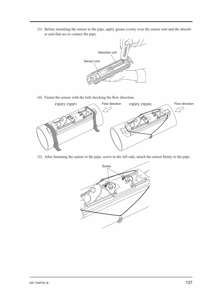
-
Absorber unit
Sensor unit
Gre
ase
FSDP2, FSDP1 FSDP2, FSDP0Flow direction Flow direction
Screw
138 INF-TN4FSC-E
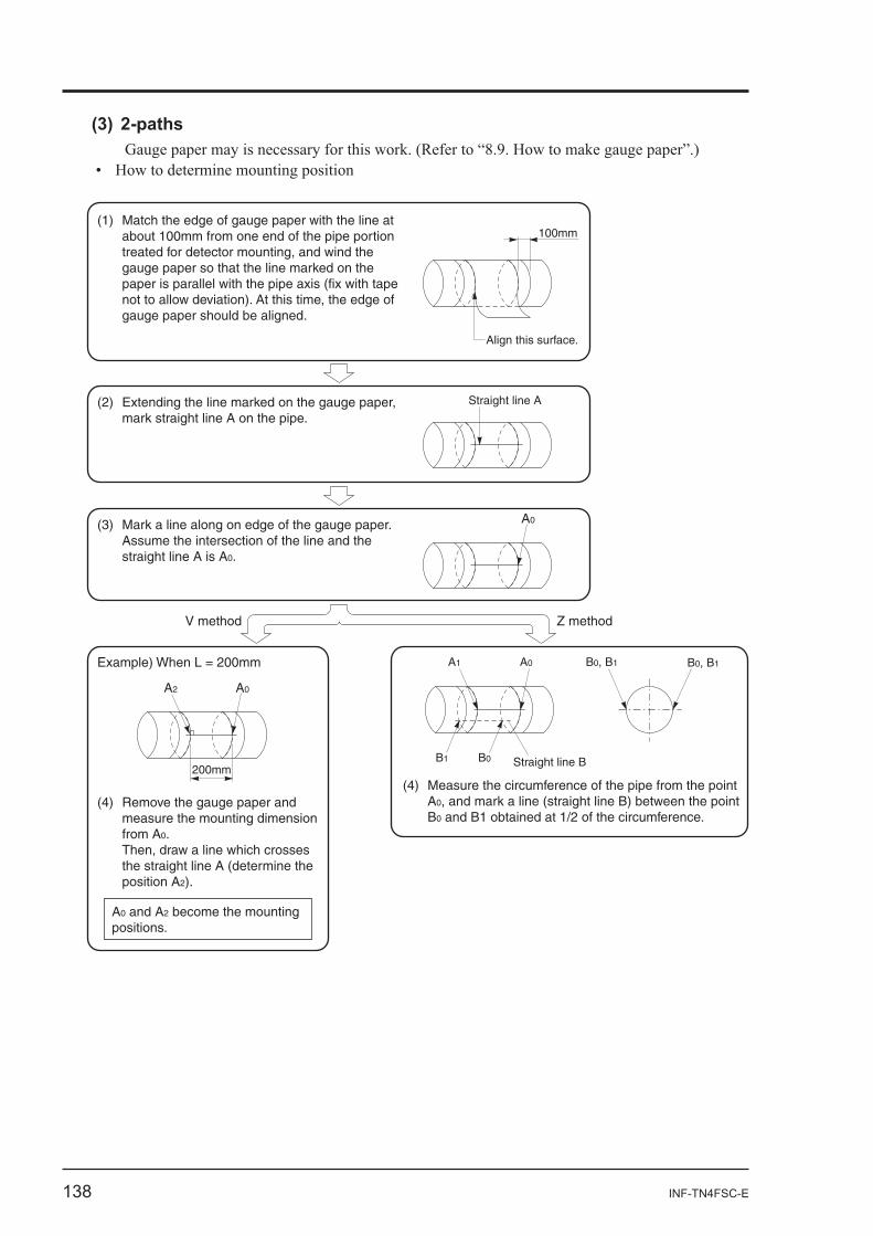
Align this surface.
100mm
Straight line A
A0
A0A2
200mm
A0A1
B1 B0 Straight line B
B0, B1B0, B1
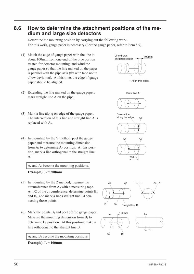
Match the edge of gauge paper with the line at about 100mm from one end of the pipe portion treated for detector mounting, and wind the gauge paper so that the line marked on the paper is parallel with the pipe axis (fix with tape not to allow deviation). At this time, the edge of gauge paper should be aligned.
(1)
Extending the line marked on the gauge paper, mark straight line A on the pipe.
(2)
Mark a line along on edge of the gauge paper. Assume the intersection of the line and the straight line A is A0.
(3)
V method Z method
Remove the gauge paper and measure the mounting dimension from A0. Then, draw a line which crosses the straight line A (determine the position A2).
(4)Measure the circumference of the pipe from the point A0, and mark a line (straight line B) between the point B0 and B1 obtained at 1/2 of the circumference.
(4)
A0 and A2 become the mounting positions.
Example) When L = 200mm
INF-TN4FSC-E 139
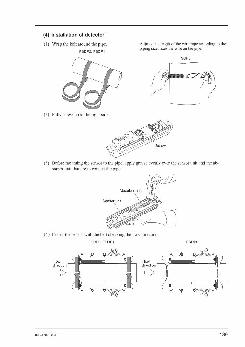
FSDP2, FSDP1
FSDP0
Screw
-
Absorber unit
Sensor unit
Gre
ase
4FSDP2, FSDP1
Flow direction
Flow direction
FSDP0
140 INF-TN4FSC-E
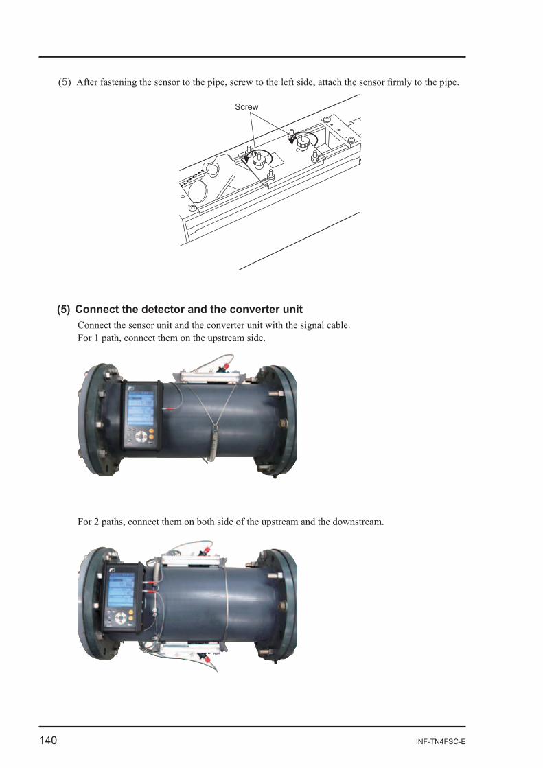
5
Screw
INF-TN4FSC-E 141
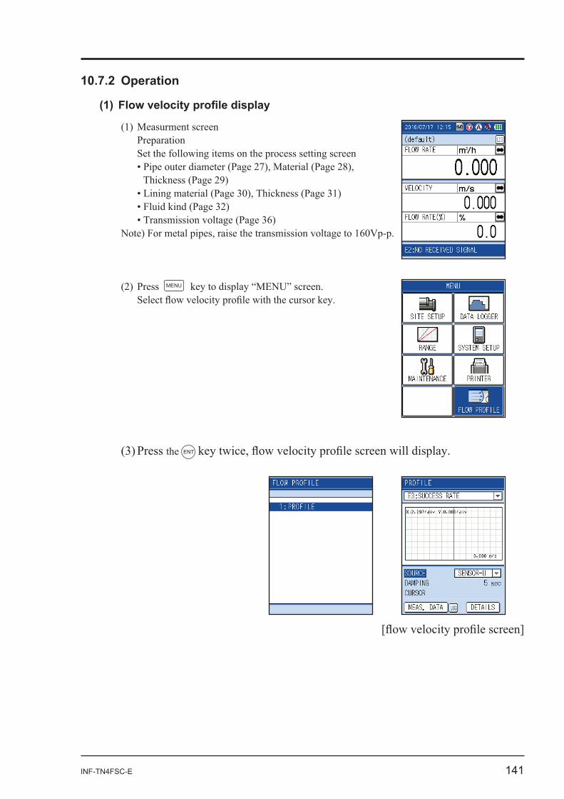
Preparation
MENU
the ENT
142 INF-TN4FSC-E
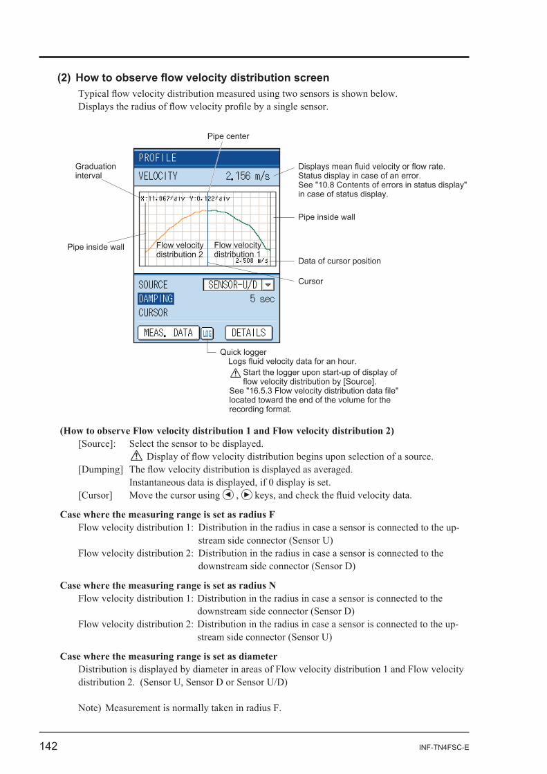
Pipe inside wall
Graduation interval
Flow velocity distribution 2
Flow velocity distribution 1
Pipe center
Displays mean fluid velocity or flow rate. Status display in case of an error. See "10.8 Contents of errors in status display" in case of status display.
Pipe inside wall
Data of cursor position
Cursor
Quick loggerLogs fluid velocity data for an hour.
Start the logger upon start-up of display of flow velocity distribution by [Source].
See "16.5.3 Flow velocity distribution data file" located toward the end of the volume for the recording format.
-
-
INF-TN4FSC-E 143
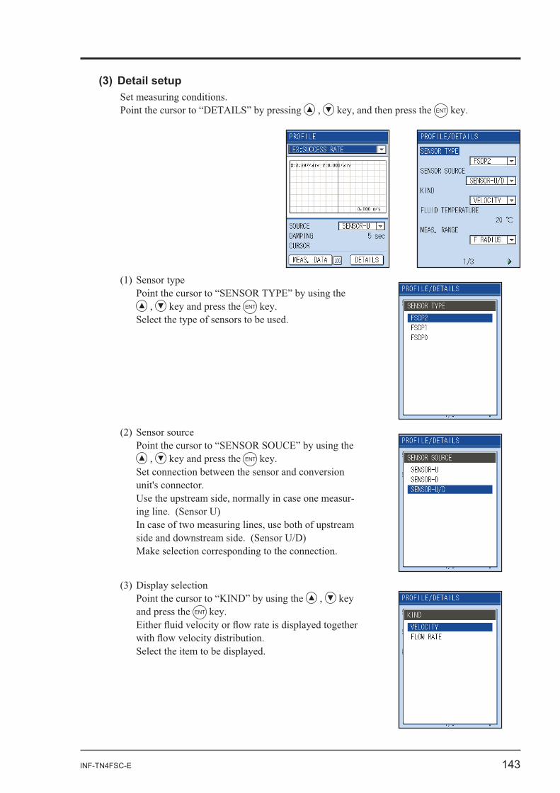
ENT
ENT
ENT
Set connection between the sensor and conversion
-
and press the ENT
144 INF-TN4FSC-E
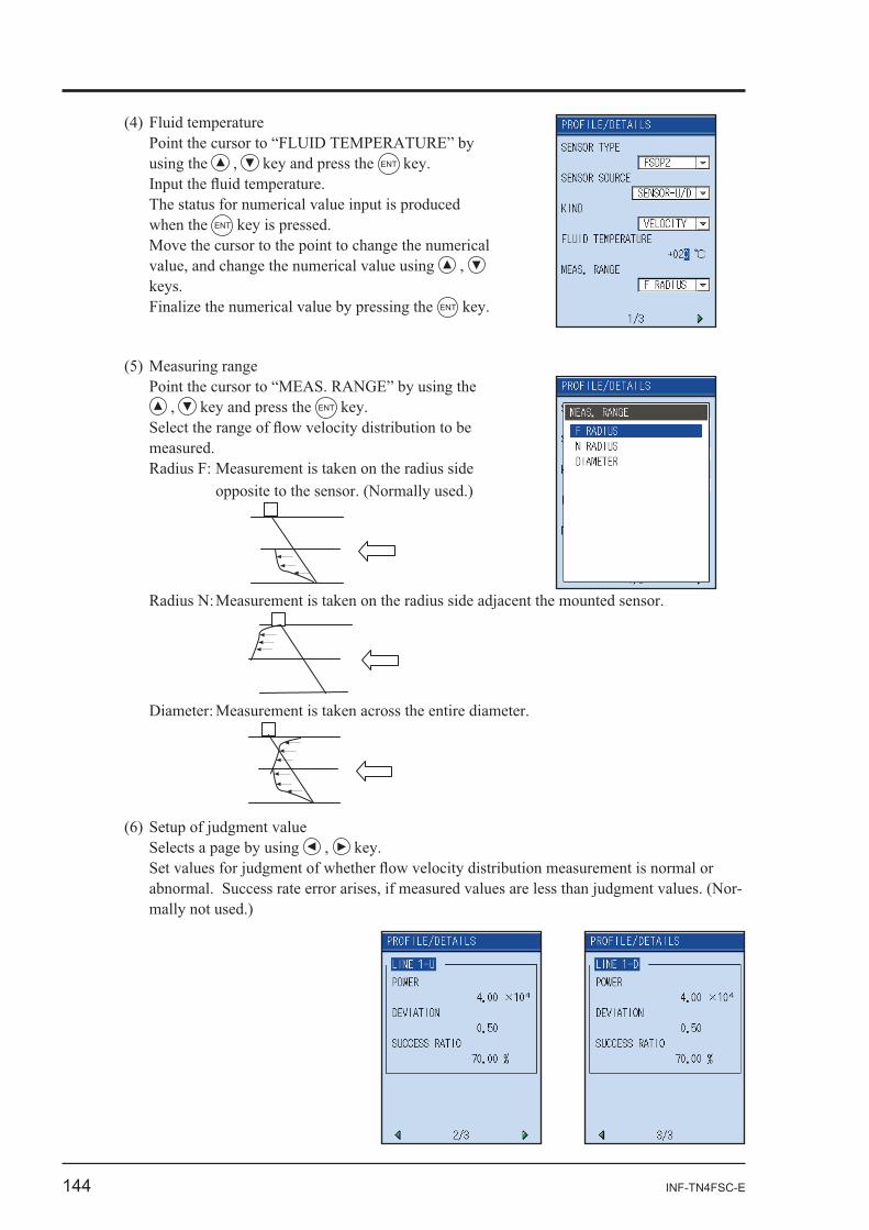
ENT
when the ENT
ENT
ENT
-
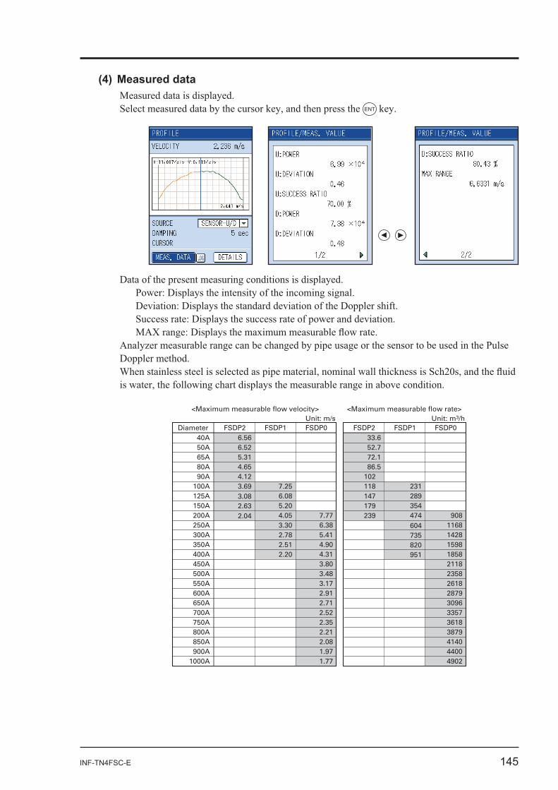
INF-TN4FSC-E 145
ENT
<Maximum measurable flow velocity>Unit: m/s
<Maximum measurable flow rate>Unit: m3/h
Diameter
50A
FSDP2
6.52
FSDP1 FSDP0
65A 5.3180A 4.6590A 4.12
100A 3.693.082.632.04
7.25125A 6.08150A 5.20200A 4.05
3.302.782.512.20
7.77250A 6.38300A 5.41350A 4.90400A 4.31450A 3.80500A 3.48550A 3.17600A 2.91650A 2.71700A 2.52750A 2.35800A 2.21850A 2.08900A 1.97
1000A 1.77
FSDP2
52.740A 6.56 33.6
FSDP1 FSDP0
72.186.5
102118147179239
231289354474604735820951
908116814281598185821182358261828793096335736183879414044004902
146 INF-TN4FSC-E
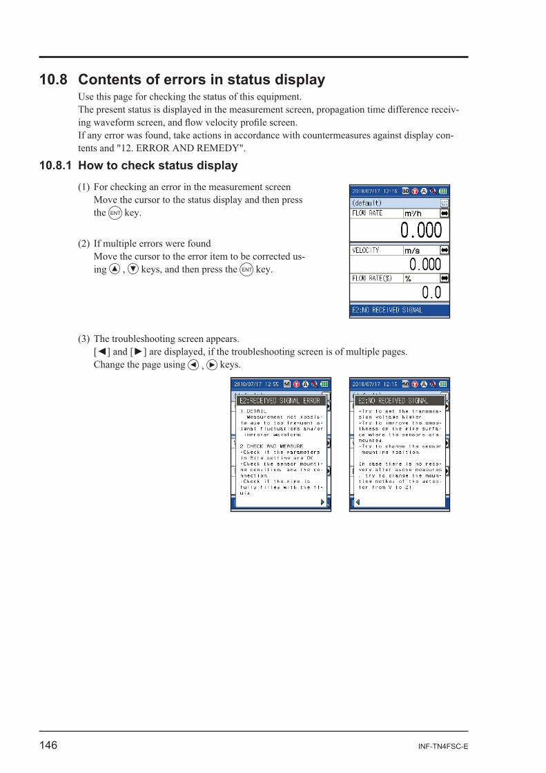
-
-
Move the cursor to the status display and then press the ENT
-
ENT
INF-TN4FSC-E 147
148 INF-TN4FSC-E
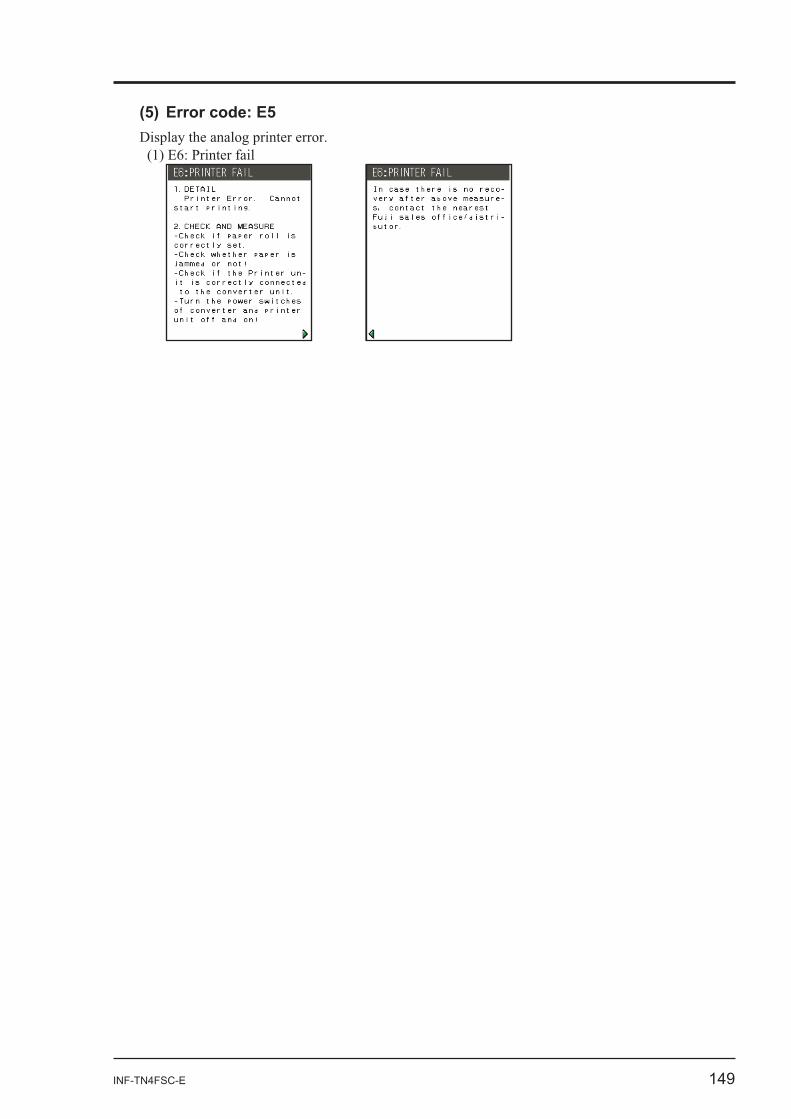
INF-TN4FSC-E 149
150 INF-TN4FSC-E
11. MAINTENANCE AND CHECKUP
-
-
-
INF-TN4FSC-E 151
-
-
-
-
152 INF-TN4FSC-E
-
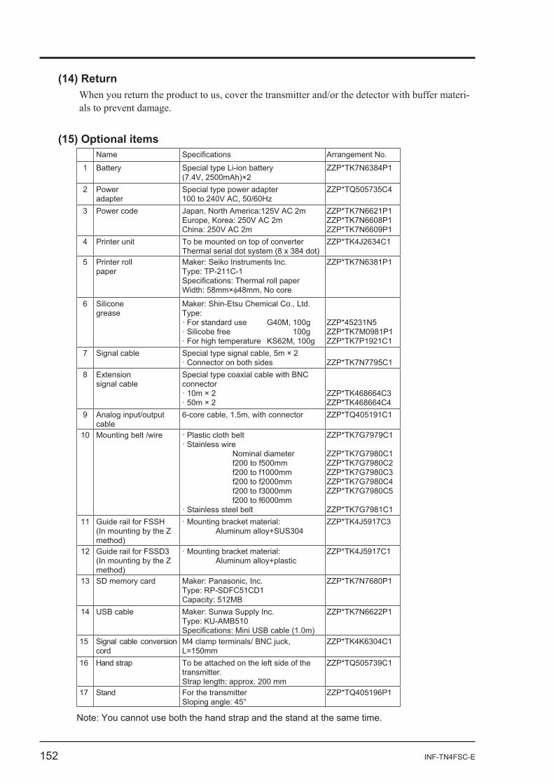
Name Arrangement No.
1 Battery Special type Li-ion battery(7.4V, 2500mAh)×2
ZZP*TK7N6384P1
2 Poweradapter
Special type power adapter ZZP*TQ505735C4
3 Power code Japan, North America:125V AC 2mEurope, Korea: 250V AC 2mChina: 250V AC 2m
ZZP*TK7N6621P1ZZP*TK7N6608P1ZZP*TK7N6609P1
4 Printer unit To be mounted on top of converterThermal serial dot system (8 x 384 dot)
ZZP*TK4J2634C1
5 Printer roll paper
Maker: Seiko Instruments Inc. Type: TP-211C-1
Width: 58mm× 48mm, No core
ZZP*TK7N6381P1
6 Silicone grease
Maker: Shin-Etsu Chemical Co., Ltd. Type:· For standard use G40M, 100g· Silicobe free 100g· For high temperature KS62M, 100g
ZZP*45231N5ZZP*TK7M0981P1ZZP*TK7P1921C1
7 Signal cable Special type signal cable, 5m × 2· Connector on both sides ZZP*TK7N7795C1
8 Extension signal cable
Special type coaxial cable with BNC connector· 10m × 2· 50m × 2
ZZP*TK468664C3ZZP*TK468664C4
9 Analog input/output cable
6-core cable, 1.5m, with connector ZZP*TQ405191C1
10 Mounting belt /wire · Plastic cloth belt· Stainless wire Nominal diameter f200 to f500mm f200 to f1000mm f200 to f2000mm f200 to f3000mm f200 to f6000mm· Stainless steel belt
ZZP*TK7G7979C1
ZZP*TK7G7980C1ZZP*TK7G7980C2ZZP*TK7G7980C3ZZP*TK7G7980C4ZZP*TK7G7980C5
ZZP*TK7G7981C111 Guide rail for FSSH
(In mounting by the Z method)
· Mounting bracket material: Aluminum alloy+SUS304
ZZP*TK4J5917C3
12 Guide rail for FSSD3 (In mounting by the Z method)
· Mounting bracket material: Aluminum alloy+plastic
ZZP*TK4J5917C1
13 SD memory card Maker: Panasonic, Inc. Type: RP-SDFC51CD1Capacity: 512MB
ZZP*TK7N7680P1
14 USB cable Maker: Sunwa Supply Inc. Type: KU-AMB510
ZZP*TK7N6622P1
15 Signal cable conversion cord L=150mm
ZZP*TK4K6304C1
16 Hand strap To be attached on the left side of the transmitter. Strap length: approx. 200 mm
ZZP*TQ505739C1
17 Stand For the transmitter Sloping angle: 45°
ZZP*TQ405196P1
Note: You cannot use both the hand strap and the stand at the same time.
INF-TN4FSC-E 153
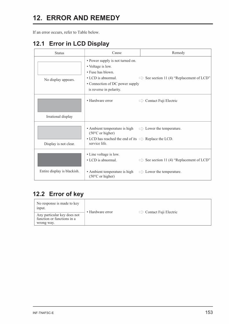
12. ERROR AND REMEDY
12.1 Error in LCD DisplayStatus Cause Remedy
No display appears.
No response is made to keyinput.
Any particular key does notfunction or functions in a
Contact Fuji Electric
154 INF-TN4FSC-E
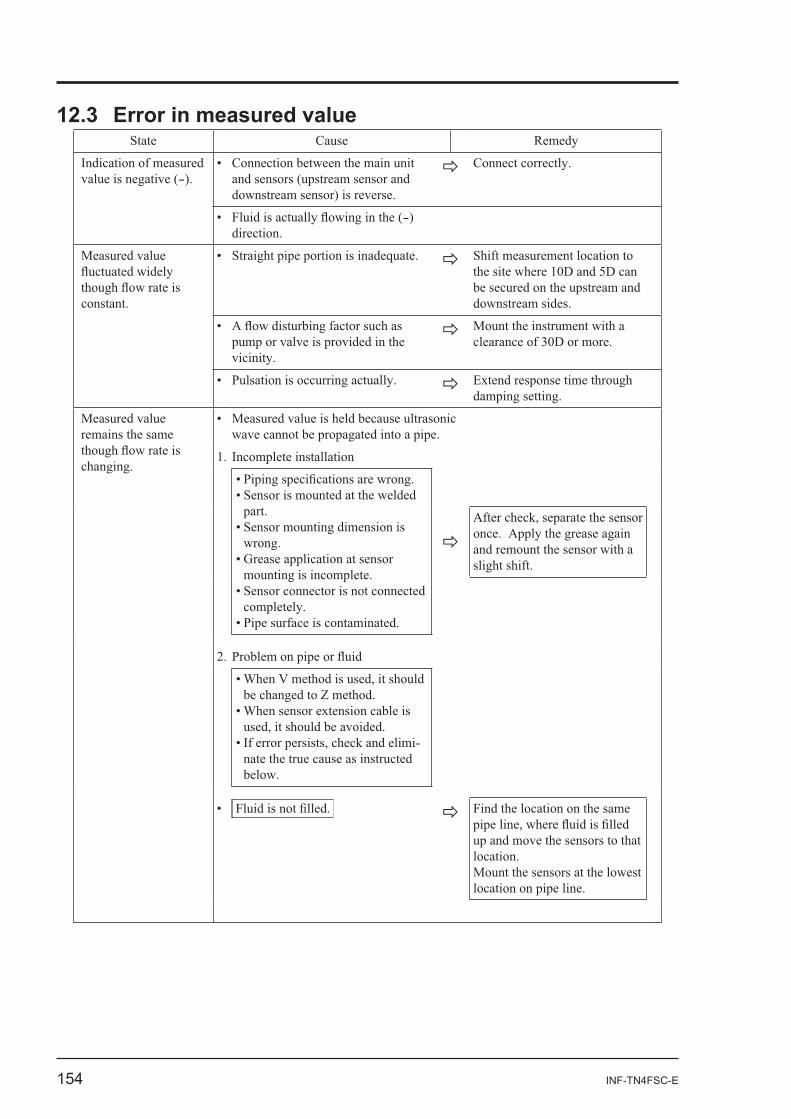
State Cause
-
-)
Measured value
Measured value Measured value is held because ultrasonic
-nate the true cause as instructed
Mount the sensors at the lowest
INF-TN4FSC-E 155
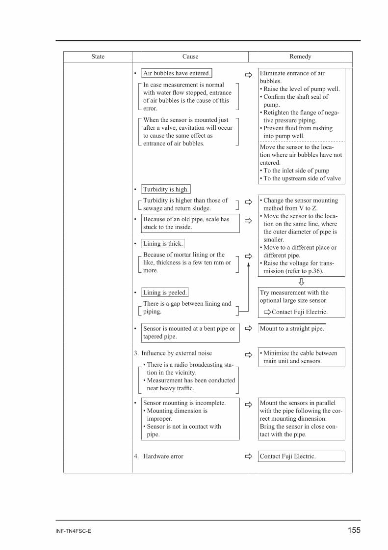
State Cause
of air bubbles is the cause of this
-
Move the sensor to the loca-tion where air bubbles have not
-
-
-
Mount the sensors in parallel
-
-
156 INF-TN4FSC-E
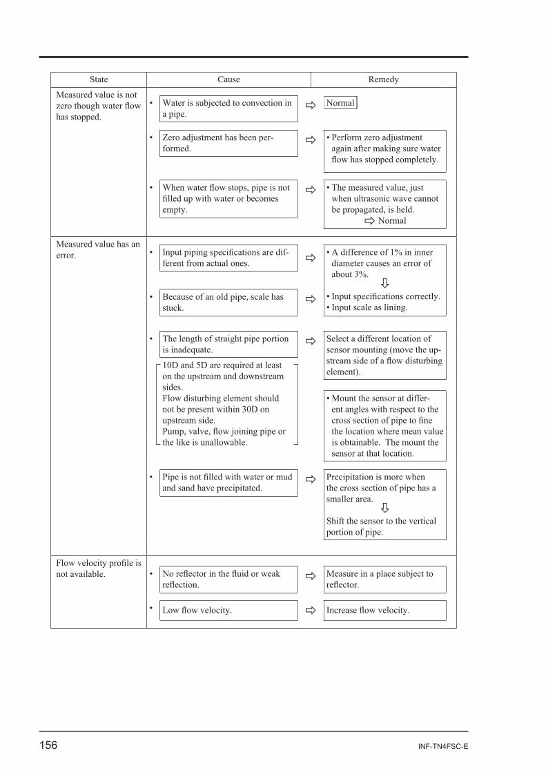
State Cause
Measured value is not Water is subjected to convection in
-
when ultrasonic wave cannot
Measured value has an -
Select a different location of
-
the cross section of pipe has a
Shift the sensor to the vertical
Measure in a place subject to
INF-TN4FSC-E 157
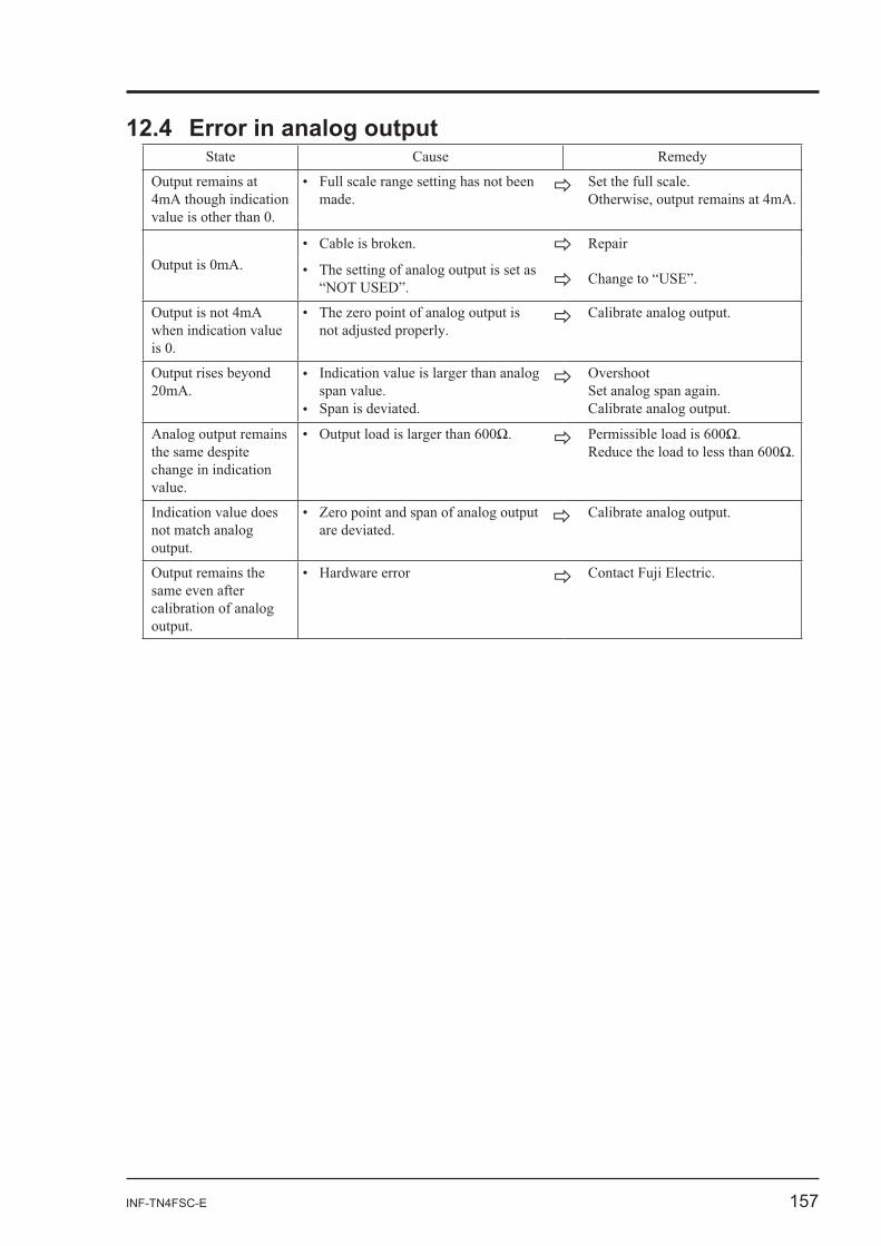
12.4 Error in analog outputState Cause
when indication value
Output rises beyond Overshoot
Indication value does
158 INF-TN4FSC-E
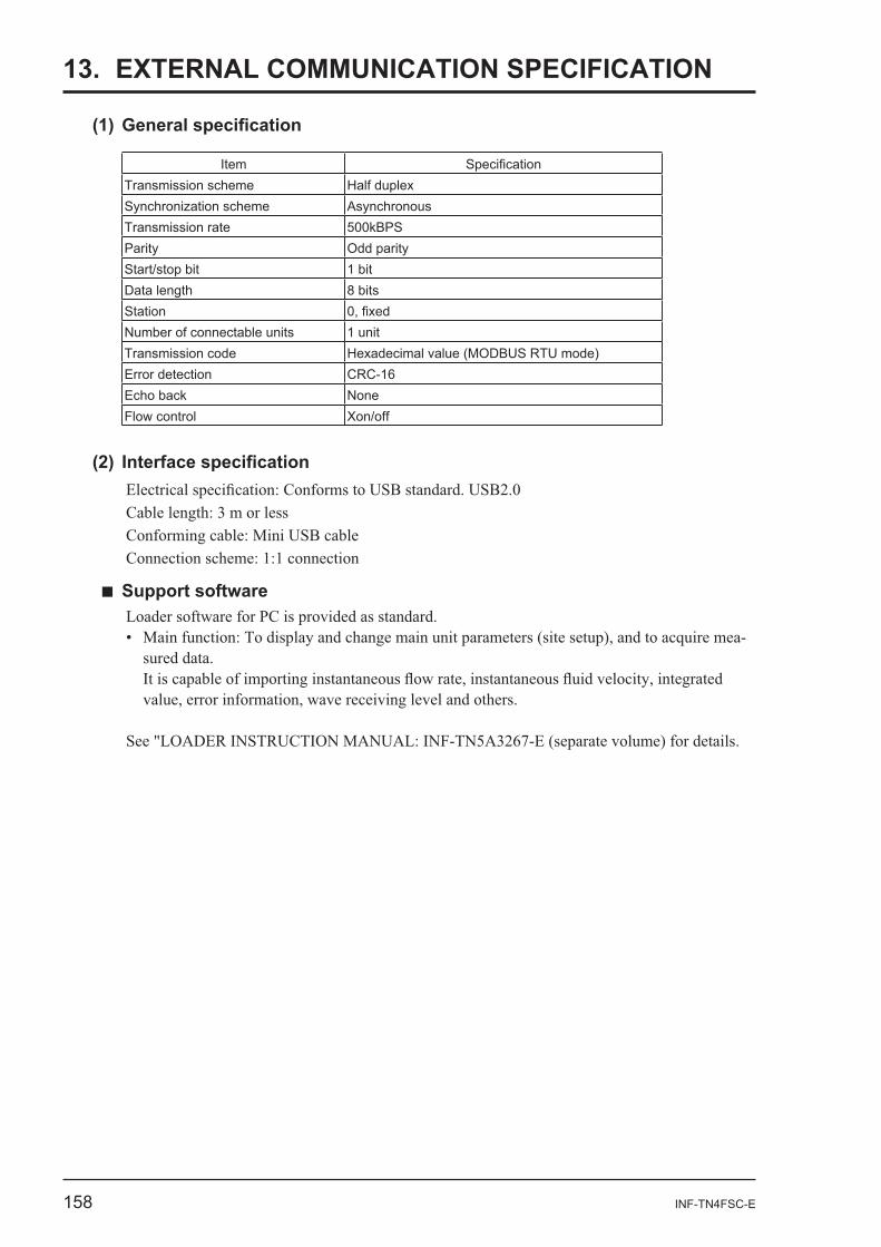
13. EXTERNAL COMMUNICATION SPECIFICATION
ItemTransmission scheme Half duplex
AsynchronousTransmission rate 500kBPSParity Odd parityStart/stop bit 1 bitData length 8 bitsStationNumber of connectable units 1 unitTransmission code Hexadecimal value (MODBUS RTU mode)Error detection CRC-16Echo back NoneFlow control Xon/off
-
INF-TN4FSC-E 159
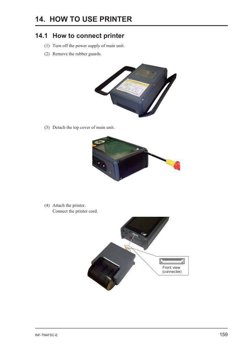
14. HOW TO USE PRINTER
Front view (connecter)
160 INF-TN4FSC-E
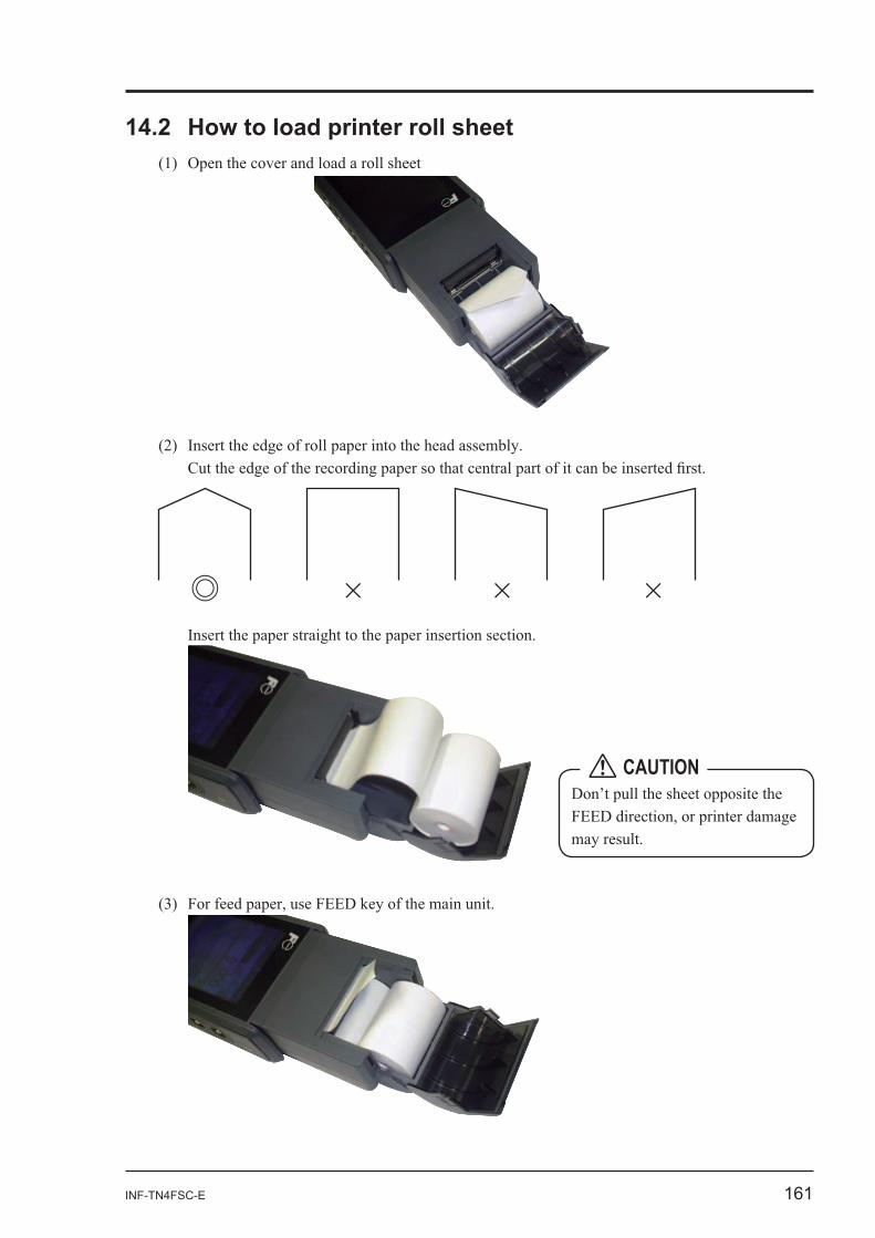
INF-TN4FSC-E 161
Don’t pull the sheet opposite the CAUTION
162 INF-TN4FSC-E
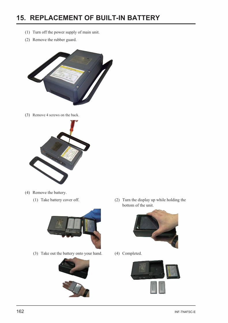
15. REPLACEMENT OF BUILT-IN BATTERY
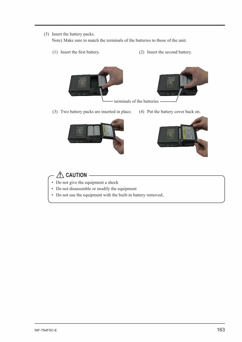
INF-TN4FSC-E 163
CAUTION
164 INF-TN4FSC-E
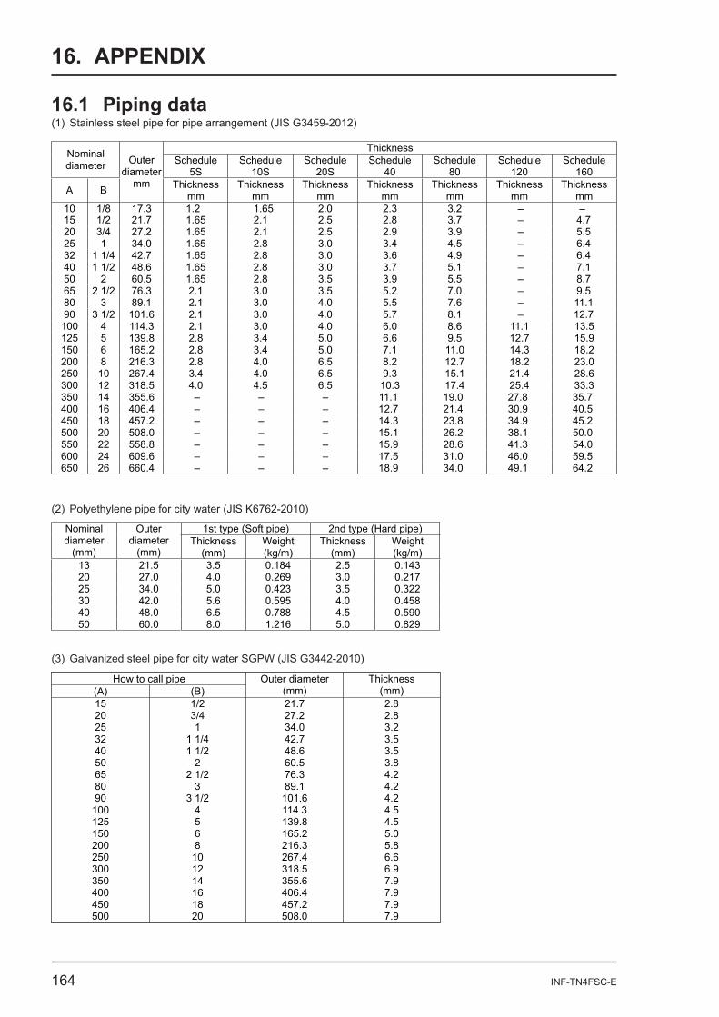
16. APPENDIX
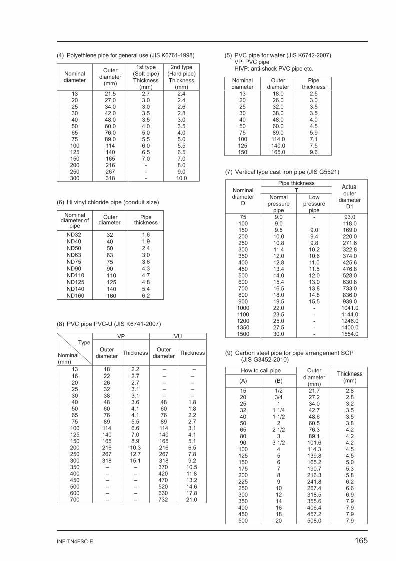
16.1 Piping data (1) Stainless steel pipe for pipe arrangement (JIS G3459-2012)
(2) Polyethylene pipe for city water (JIS K6762-2010)
Thickness Nominal diameter Schedule
5SSchedule
10SSchedule
20SSchedule
40Schedule
80Schedule
120Schedule
160
A B
Outerdiameter
mm Thickness mm
Thickness mm
Thickness mm
Thickness mm
Thickness mm
Thickness mm
Thickness mm
15 1/2 21.7 1.65 2.1 2.5 2.8 3.7 – 4.7 10 1/8 17.3 1.2 1.65 2.0 2.3 3.2 – –
20 3/4 27.2 1.65 2.1 2.5 2.9 3.9 – 5.5 25 1 34.0 1.65 2.8 3.0 3.4 4.5 – 6.4 32 1 1/4 42.7 1.65 2.8 3.0 3.6 4.9 – 6.4 40 1 1/2 48.6 1.65 2.8 3.0 3.7 5.1 – 7.1 50 2 60.5 1.65 2.8 3.5 3.9 5.5 – 8.7 65 2 1/2 76.3 2.1 3.0 3.5 5.2 7.0 – 9.5 80 3 89.1 2.1 3.0 4.0 5.5 7.6 – 11.1 90 3 1/2 101.6 2.1 3.0 4.0 5.7 8.1 – 12.7 100 4 114.3 2.1 3.0 4.0 6.0 8.6 11.1 13.5 125 5 139.8 2.8 3.4 5.0 6.6 9.5 12.7 15.9 150 6 165.2 2.8 3.4 5.0 7.1 11.0 14.3 18.2 200 8 216.3 2.8 4.0 6.5 8.2 12.7 18.2 23.0 250 10 267.4 3.4 4.0 6.5 9.3 15.1 21.4 28.6 300 12 318.5 4.0 4.5 6.5 10.3 17.4 25.4 33.3 350 14 355.6 – – – 11.1 19.0 27.8 35.7 400 16 406.4 – – – 12.7 21.4 30.9 40.5 450 18 457.2 – – – 14.3 23.8 34.9 45.2 500 20 508.0 – – – 15.1 26.2 38.1 50.0 550 22 558.8 – – – 15.9 28.6 41.3 54.0 600 24 609.6 – – – 17.5 31.0 46.0 59.5 650 26 660.4 – – – 18.9 34.0 49.1 64.2
1st type (Soft pipe) 2nd type (Hard pipe) Nominal diameter
(mm)
Outerdiameter
(mm)Thickness
(mm)Weight (kg/m)
Thickness(mm)
Weight (kg/m)
13 21.5 3.5 0.184 2.5 0.143 20 27.0 4.0 0.269 3.0 0.217 25 34.0 5.0 0.423 3.5 0.322 30 42.0 5.6 0.595 4.0 0.458 40 48.0 6.5 0.788 4.5 0.590 50 60.0 8.0 1.216 5.0 0.829
How to call pipe (A) (B)
Outer diameter (mm)
Thickness (mm)
15 1/2 21.7 2.8 20 3/4 27.2 2.8 25 1 34.0 3.2 32 1 1/4 42.7 3.5 40 1 1/2 48.6 3.5 50 2 60.5 3.8 65 2 1/2 76.3 4.2 80 3 89.1 4.2 90 3 1/2 101.6 4.2
100 4 114.3 4.5 125 5 139.8 4.5 150 6 165.2 5.0 200 8 216.3 5.8 250 10 267.4 6.6 300 12 318.5 6.9 350 14 355.6 7.9 400 16 406.4 7.9 450 18 457.2 7.9 500 20 508.0 7.9
INF-TN4FSC-E 165
(4) Polyethlene pipe for general use (JIS K6761-1998)
1st type (Soft pipe)
2nd type (Hard pipe)Nominal
diameter
Outerdiameter
(mm) Thickness (mm)
Thickness(mm)
13 21.5 2.7 2.4 20 27.0 3.0 2.4 25 34.0 3.0 2.6 30 42.0 3.5 2.8 40 48.0 3.5 3.0 50 60.0 4.0 3.5 65 76.0 5.0 4.0 75 89.0 5.5 5.0
100 114 6.0 5.5 125 140 6.5 6.5 150 165 7.0 7.0 200 216 - 8.0 250 267 - 9.0 300 318 - 10.0
(5) PVC pipe for water (JIS K6742-2007) VP: PVC pipe HIVP: anti-shock PVC pipe etc.
Nominal diameter
Outerdiameter
Pipethickness
13 18.0 2.5 20 26.0 3.0 25 32.0 3.5 30 38.0 3.5 40 48.0 4.0 50 60.0 4.5 75 89.0 5.9
100 114.0 7.1 125 140.0 7.5 150 165.0 9.6
324050637590110125140160
1.61.92.43.03.64.34.74.85.46.2
ND32ND40ND50ND63ND75ND90ND110ND125ND140ND160
Nominaldiameter of
pipeOuter
diameter Pipe
thickness
(7) Vertical type cast iron pipe (JIS G5521)
Pipe thickness TNominal
diameter D
Normalpressure
pipe
Low pressure
pipe
Actualouter
diameter D1
75 9.0 - 93.0 100 9.0 - 118.0 150 9.5 9.0 169.0 200 10.0 9.4 220.0 250 10.8 9.8 271.6 300 11.4 10.2 322.8 350 12.0 10.6 374.0 400 12.8 11.0 425.6 450 13.4 11.5 476.8 500 14.0 12.0 528.0 600 15.4 13.0 630.8 700 16.5 13.8 733.0 800 18.0 14.8 836.0 900 19.5 15.5 939.0
1000 22.0 - 1041.0 1100 23.5 - 1144.0 1200 25.0 - 1246.0 1350 27.5 - 1400.0 1500 30.0 - 1554.0
(9) Carbon steel pipe for pipe arrangement SGP (JIS G3452-2010)
(8) PVC pipe PVC-U (JIS K6741-2007)
How to call pipe
(A) (B)
Outerdiameter
(mm)
Thickness(mm)
15 1/2 21.7 2.8 20 3/4 27.2 2.8 25 1 34.0 3.2 32 1 1/4 42.7 3.5 40 1 1/2 48.6 3.5 50 2 60.5 3.8 65 2 1/2 76.3 4.2 80 3 89.1 4.2 90 3 1/2 101.6 4.2
100 4 114.3 4.5 125 5 139.8 4.5 150 6 165.2 5.0 175 7 190.7 5.3 200 8 216.3 5.8 225 9 241.8 6.2 250 10 267.4 6.6 300 12 318.5 6.9 350 14 355.6 7.9 400 16 406.4 7.9 450 18 457.2 7.9 500 20 508.0 7.9
VP VU Type
Nominal (mm)
Outerdiameter Thickness Outer
diameter Thickness
13 18 2.2 – – 16 22 2.7 – – 20 26 2.7 – – 25 32 3.1 – – 30 38 3.1 – – 40 48 3.6 48 1.8 50 60 4.1 60 1.8 65 76 4.1 76 2.2 75 89 5.5 89 2.7
100 114 6.6 114 3.1 125 140 7.0 140 4.1 150 165 8.9 165 5.1 200 216 10.3 216 6.5 250 267 12.7 267 7.8 300 318 15.1 318 9.2 350 – – 370 10.5 400 – – 420 11.8 450 – – 470 13.2 500 – – 520 14.6 600 – – 630 17.8 700 – – 732 21.0
166 INF-TN4FSC-E
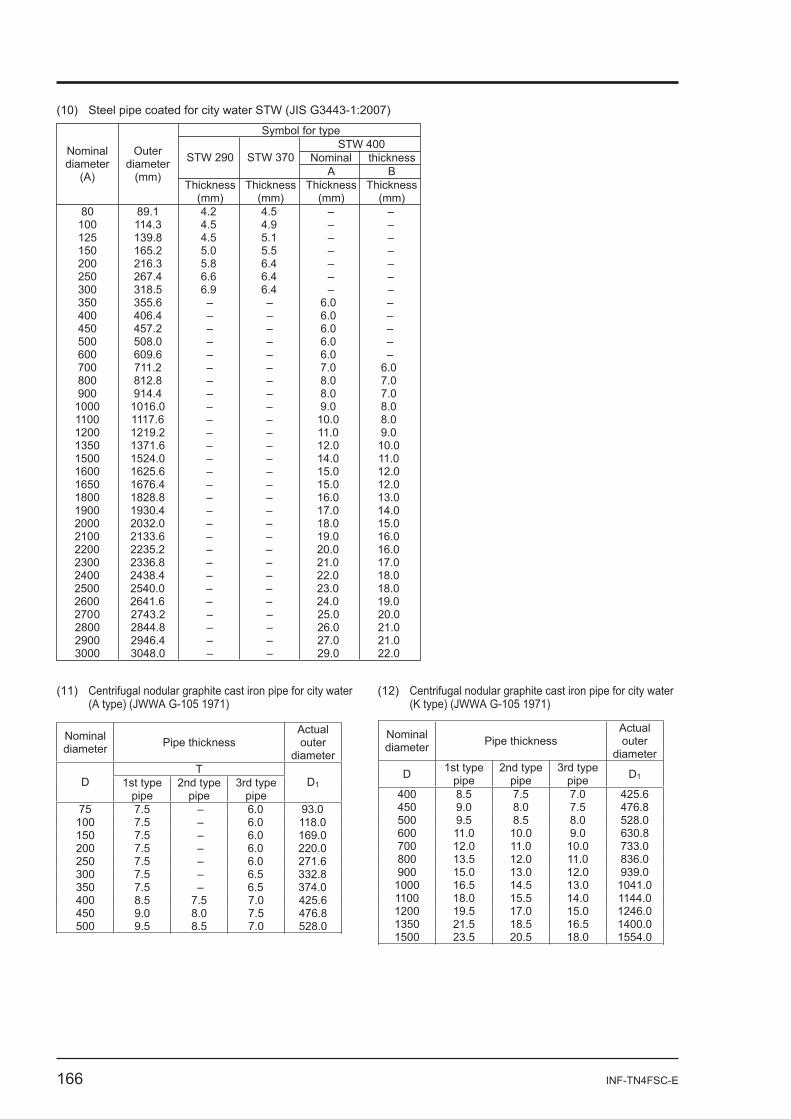
(10) Steel pipe coated for city water STW (JIS G3443-1:2007)
80 89.1 4.2 4.5 – – 100 114.3 4.5 4.9 – – 125 139.8 4.5 5.1 – – 150 165.2 5.0 5.5 – – 200 216.3 5.8 6.4 – – 250 267.4 6.6 6.4 – – 300 318.5 6.9 6.4 – – 350 355.6 – – 6.0 – 400 406.4 – – 6.0 – 450 457.2 – – 6.0 – 500 508.0 – – 6.0 – 600 609.6 – – 6.0 – 700 711.2 – – 7.0 6.0 800 812.8 – – 8.0 7.0 900 914.4 – – 8.0 7.0
1000 1016.0 – – 9.0 8.0 1100 1117.6 – – 10.0 8.0 1200 1219.2 – – 11.0 9.0 1350 1371.6 – – 12.0 10.0 1500 1524.0 – – 14.0 11.0 1600 1625.6 – – 15.0 12.0 1650 1676.4 – – 15.0 12.0 1800 1828.8 – – 16.0 13.0 1900 1930.4 – – 17.0 14.0 2000 2032.0 – – 18.0 15.0 2100 2133.6 – – 19.0 16.0 2200 2235.2 – – 20.0 16.0 2300 2336.8 – – 21.0 17.0 2400 2438.4 – – 22.0 18.0 2500 2540.0 – – 23.0 18.0 2600 2641.6 – – 24.0 19.0 2700 2743.2 – – 25.0 20.0 2800 2844.8 – – 26.0 21.0 2900 2946.4 – – 27.0 21.0 3000 3048.0 – – 29.0 22.0
Symbol for typeSTW 400
Nominal thicknessSTW 290 STW 370 A B
Nominal diameter
(A)
Outerdiameter
(mm)Thickness
(mm)Thickness
(mm)Thickness
(mm)Thickness
(mm)
(11) Centrifugal nodular graphite cast iron pipe for city water (A type) (JWWA G-105 1971)
(12) Centrifugal nodular graphite cast iron pipe for city water (K type) (JWWA G-105 1971)
Nominal diameter Pipe thickness
Actualouter
diameterT
D 1st type pipe
2nd type pipe
3rd type pipe
D1
75 7.5 – 6.0 93.0 100 7.5 – 6.0 118.0 150 7.5 – 6.0 169.0 200 7.5 – 6.0 220.0 250 7.5 – 6.0 271.6 300 7.5 – 6.5 332.8 350 7.5 – 6.5 374.0 400 8.5 7.5 7.0 425.6 450 9.0 8.0 7.5 476.8 500 9.5 8.5 7.0 528.0
Nominal diameter Pipe thickness
Actualouter
diameter
D 1st type pipe
2nd type pipe
3rd type pipe D1
400 8.5 7.5 7.0 425.6 450 9.0 8.0 7.5 476.8 500 9.5 8.5 8.0 528.0 600 11.0 10.0 9.0 630.8 700 12.0 11.0 10.0 733.0 800 13.5 12.0 11.0 836.0 900 15.0 13.0 12.0 939.0
1000 16.5 14.5 13.0 1041.01100 18.0 15.5 14.0 1144.01200 19.5 17.0 15.0 1246.01350 21.5 18.5 16.5 1400.01500 23.5 20.5 18.0 1554.0
INF-TN4FSC-E 167
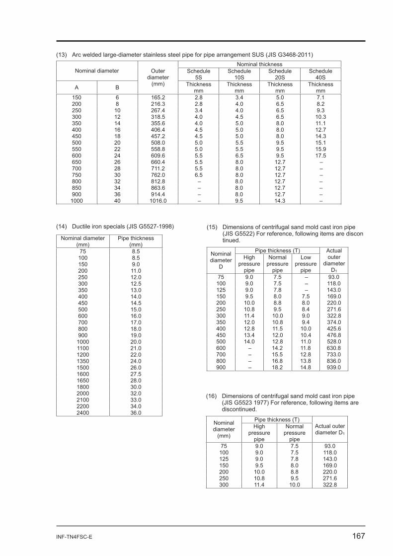
(14) Ductile iron specials (JIS G5527-1998)
(13) Arc welded large-diameter stainless steel pipe for pipe arrangement SUS (JIS G3468-2011)
Nominal diameter (mm)
Pipe thickness (mm)
75 8.5 100 8.5 150 9.0 200 11.0 250 12.0 300 12.5 350 13.0 400 14.0 450 14.5 500 15.0 600 16.0 700 17.0 800 18.0 900 19.0
1000 20.0 1100 21.0 1200 22.0 1350 24.0 1500 26.0 1600 27.5 1650 28.0 1800 30.0 2000 32.0 2100 33.0 2200 34.0 2400 36.0
Nominal thickness Nominal diameter Schedule
5SSchedule
10SSchedule
20SSchedule
40S
A B
Outerdiameter
(mm) Thickness mm
Thickness mm
Thickness mm
Thickness mm
150 6 165.2 2.8 3.4 5.0 7.1 200 8 216.3 2.8 4.0 6.5 8.2 250 10 267.4 3.4 4.0 6.5 9.3 300 12 318.5 4.0 4.5 6.5 10.3 350 14 355.6 4.0 5.0 8.0 11.1 400 16 406.4 4.5 5.0 8.0 12.7 450 18 457.2 4.5 5.0 8.0 14.3 500 20 508.0 5.0 5.5 9.5 15.1 550 22 558.8 5.0 5.5 9.5 15.9 600 24 609.6 5.5 6.5 9.5 17.5 650 26 660.4 5.5 8.0 12.7 – 700 28 711.2 5.5 8.0 12.7 – 750 30 762.0 6.5 8.0 12.7 – 800 32 812.8 – 8.0 12.7 – 850 34 863.6 – 8.0 12.7 – 900 36 914.4 – 8.0 12.7 –
1000 40 1016.0 – 9.5 14.3 –
(16) Dimensions of centrifugal sand mold cast iron pipe (JIS G5523 1977) For reference, following items are
discontinued.
Pipe thickness (T) Nominal diameter
(mm)
Highpressure
pipe
Normalpressure
pipe
Actual outer diameter D1
75 9.0 7.5 93.0 100 9.0 7.5 118.0 125 9.0 7.8 143.0 150 9.5 8.0 169.0 200 10.0 8.8 220.0 250 10.8 9.5 271.6 300 11.4 10.0 322.8
(15) Dimensions of centrifugal sand mold cast iron pipe (JIS G5522) For reference, following items are discon
tinued.
Pipe thickness (T) Nominal diameter
D
Highpressure
pipe
Normalpressure
pipe
Low pressure
pipe
Actualouter
diameter D1
75 9.0 7.5 – 93.0 100 9.0 7.5 – 118.0 125 9.0 7.8 – 143.0 150 9.5 8.0 7.5 169.0 200 10.0 8.8 8.0 220.0 250 10.8 9.5 8.4 271.6 300 11.4 10.0 9.0 322.8 350 12.0 10.8 9.4 374.0 400 12.8 11.5 10.0 425.6 450 13.4 12.0 10.4 476.8 500 14.0 12.8 11.0 528.0 600 – 14.2 11.8 630.8 700 – 15.5 12.8 733.0 800 – 16.8 13.8 836.0 900 – 18.2 14.8 939.0
168 INF-TN4FSC-E
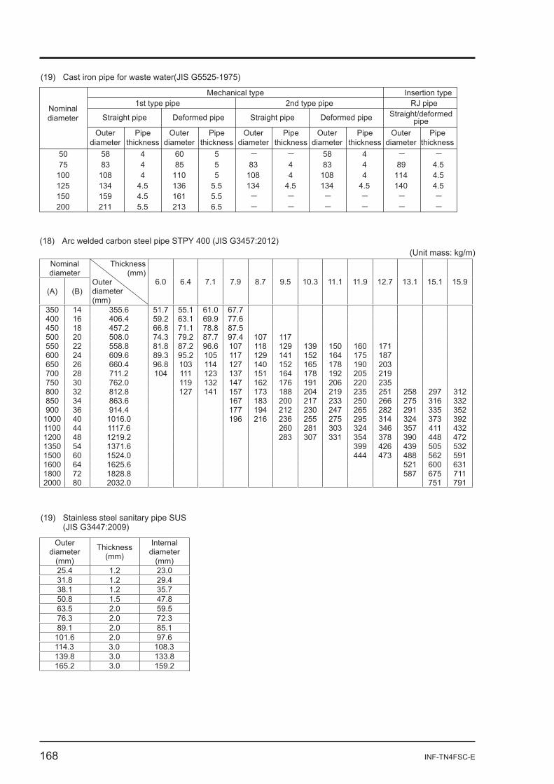
(18) Arc welded carbon steel pipe STPY 400 (JIS G3457:2012)(Unit mass: kg/m)
Nominal diameter
(A) (B)
Thickness (mm)
Outerdiameter (mm)
6.0 6.4 7.1 7.9 8.7 9.5 10.3 11.1 11.9 12.7 13.1 15.1 15.9
350 14 355.6 51.7 55.1 61.0 67.7 400 16 406.4 59.2 63.1 69.9 77.6 450 18 457.2 66.8 71.1 78.8 87.5 500 20 508.0 74.3 79.2 87.7 97.4 107 117 550 22 558.8 81.8 87.2 96.6 107 118 129 139 150 160 171 600 24 609.6 89.3 95.2 105 117 129 141 152 164 175 187 650 26 660.4 96.8 103 114 127 140 152 165 178 190 203 700 28 711.2 104 111 123 137 151 164 178 192 205 219 750 30 762.0 119 132 147 162 176 191 206 220 235 800 32 812.8 127 141 157 173 188 204 219 235 251 258 297 312850 34 863.6 167 183 200 217 233 250 266 275 316 332900 36 914.4 177 194 212 230 247 265 282 291 335 352
1000 40 1016.0 196 216 236 255 275 295 314 324 373 3921100 44 1117.6 260 281 303 324 346 357 411 4321200 48 1219.2 283 307 331 354 378 390 448 4721350 54 1371.6 399 426 439 505 5321500 60 1524.0 444 473 488 562 5911600 64 1625.6 521 600 6311800 72 1828.8 587 675 7112000 80 2032.0 751 791
(19) Cast iron pipe for waste water(JIS G5525-1975)
58 4 - -83 4 89 4.5
108 4 114 4.5134 4.5 140 4.5- - - -- - - -
- -83 4
108 4134 4.5- -- -
Nominaldiameter
Outerdiameter
Outerdiameter
50 58 4 60 575 83 4 85 5
100 108 4 110 5125 134 4.5 136 5.5150 159 4.5 161 5.5200 211 5.5 213 6.5
Pipethickness
Pipethickness
Outerdiameter
Pipethickness
Outerdiameter
Pipethickness
Outerdiameter
Pipethickness
Mechanical type Insertion type1st type pipe 2nd type pipe RJ pipe
Straight pipe Deformed pipe Straight pipe Deformed pipe Straight/deformedpipe
(19) Stainless steel sanitary pipe SUS (JIS G3447:2009)
Outerdiameter
(mm)
Thickness (mm)
Internaldiameter
(mm)25.4 1.2 23.0 31.8 1.2 29.4 38.1 1.2 35.7 50.8 1.5 47.8 63.5 2.0 59.5 76.3 2.0 72.3 89.1 2.0 85.1
101.6 2.0 97.6 114.3 3.0 108.3 139.8 3.0 133.8 165.2 3.0 159.2
INF-TN4FSC-E 169
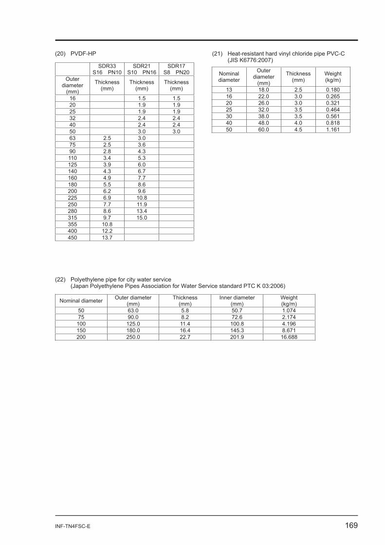
(20) PVDF-HP (21) Heat-resistant hard vinyl chloride pipe PVC-C (JIS K6776:2007)
(22) Polyethylene pipe for city water service (Japan Polyethylene Pipes Association for Water Service standard PTC K 03:2006)
SDR33 S16 PN10
SDR21 S10 PN16
SDR17 S8 PN20
Outerdiameter
(mm)
Thickness (mm)
Thickness (mm)
Thickness (mm)
16 1.5 1.5 20 1.9 1.9 25 1.9 1.9 32 2.4 2.4 40 2.4 2.4 50 3.0 3.0 63 2.5 3.0 75 2.5 3.6 90 2.8 4.3 110 3.4 5.3 125 3.9 6.0 140 4.3 6.7 160 4.9 7.7 180 5.5 8.6 200 6.2 9.6 225 6.9 10.8 250 7.7 11.9 280 8.6 13.4 315 9.7 15.0 355 10.8 400 12.2 450 13.7
Nominal diameter
Outerdiameter
(mm)
Thickness (mm)
Weight (kg/m)
13 18.0 2.5 0.180 16 22.0 3.0 0.265 20 26.0 3.0 0.321 25 32.0 3.5 0.464 30 38.0 3.5 0.561 40 48.0 4.0 0.818 50 60.0 4.5 1.161
Nominal diameter Outer diameter (mm)
Thickness (mm)
Inner diameter (mm)
Weight (kg/m)
50 63.0 5.8 50.7 1.074 75 90.0 8.2 72.6 2.174
100 125.0 11.4 100.8 4.196 150 180.0 16.4 145.3 8.671 200 250.0 22.7 201.9 16.688
170 INF-TN4FSC-E
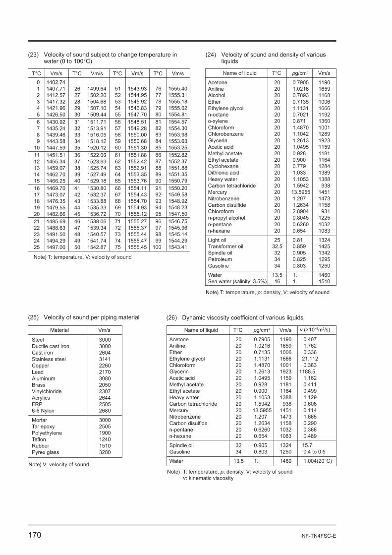
T°C
0 1402.741 1407.712 1412.573 1417.324 1421.965 1426.506 1430.927 1435.248 1439.469 1443.58
10 1447.5911 1451.5112 1455.34
Name of liquid
AcetoneAniline
EtherEthylene glycol
Chloroform
Acetic acidMethyl acetateEthyl acetate
Heavy waterCarbon tetrachlorideMercuryNitrobenzeneCarbon disulfide
n-pentanen-hexane
Light oil
Gasoline
Water
T°C g/cm3 Vm/s
2020
2020
20
202020
2020202020
2020
25
34
13.5
0.7905 1.0216
0.7135 1.1131
1.4870
1.0495 0.928 0.900
1.1053 1.594213.5955 1.207 1.2634
0.6260 0.654
0.81
0.803
1.
11901659
10061666
1001
115911811164
1388938
145114731158
10321083
1324
1250
1460
Glycerin 20 1.2613 1923
Note) T: temperature, : density, V: velocity of sound
Vm/s T°C Vm/s T°C Vm/s T°C Vm/s
13141516171819202122232425
1459.071462.701466.251469.701473.071476.351479.551482.661485.691488.631491.501494.291497.00
26 1499.6427 1502.2028 1504.6829 1507.1030 1509.4431 1511.7132 1513.9133 1516.0534 1518.1235 1520.12
.36 1522.0637 1523.9338394041424344454647484950
1525.741527.491529.181530.801532.371533.881535.331536.721538.061539.341540.571541.741542.87
51 1543.9352 1544.9553 1545.9254 1546.8355 1547.7056 1548.5157 1549.2858 1550.0059 1550.6860 1551.3061 1551.8862 1552.4263646566676869707172737475
1552.911553.351553.761554.111554.431554.701554.931555.121555.271555.371555.441555.471555.45
76 1555.4077 1555.3178 1555.1879 1555.0280 1554.8181 1554.5782 1554.3083 1553.9884 1553.6385 1553.2586 1552.8287 1552.37888990919293949596979899
100
1551.881551.351550.791550.201549.581548.921548.231547.501546.751545.961545.141544.291543.41
Note) T: temperature, V: velocity of sound
Alcohol 20 0.7893 1168
n-octane 20 0.7021 1192o-xylene 20 0.871 1360
Chlorobenzene 20 1.1042 1289
Cyclohexane 20 0.779 1284Dithionic acid 20 1.033 1389
n-propyl alcohol 20 0.8045 1225Chloroform 20 2.8904 931
Transformer oil 32.5 0.859 1425Spindle oil 32 0.905 1342Petroleum 34 0.825 1295
Sea water (salinity: 3.5%) 16 1. 1510
Material
Steel
Cast ironStainless steel
Aluminum
AcrylicsFRP
Mortar
Teflon
Vm/s
3000
26043141
3080
26442505
6-6 Nylon 2680
3000
1240
Vinylchloride 2307
Note) V: velocity of sound
Ductile cast iron 3000
Copper 2260Lead 2170
Brass 2050
Tar epoxy 2505Polyethylene 1900
Pyrex glass 3280Rubber 1510
Name of liquid
AcetoneAnilineEtherEthylene glycolChloroform
Acetic acidMethyl acetateEthyl acetateHeavy waterCarbon tetrachlorideMercuryNitrobenzeneCarbon disulfiden-pentanen-hexane
Spindle oilGasoline
Water
T°C g/cm3 Vm/s (×10 m2/s)
2020202020
20202020202020202020
3234
13.5
0.7905 1.0216 0.7135 1.1131 1.4870
1.0495 0.928 0.900 1.1053 1.594213.5955 1.207 1.2634 0.6260 0.654
0.905 0.803
1.
11901659100616661001
1159118111641388938
14511473115810321083
13241250
1460
0.407 1.762 0.336 21.112 0.383
1.162 0.411 0.499 1.129 0.608 0.114 1.665 0.290 0.366 0.489
15.7 0.4 to 0.5
1.004(20°C)
Glycerin 20 1.2613 1923 1188.5
Note) T: temperature, : density, V: velocity of sound : kinematic viscosity
water (0 to 100°C)(24) Velocity of sound and density of various
liquids
(25) Velocity of sound per piping material
INF-TN4FSC-E 171
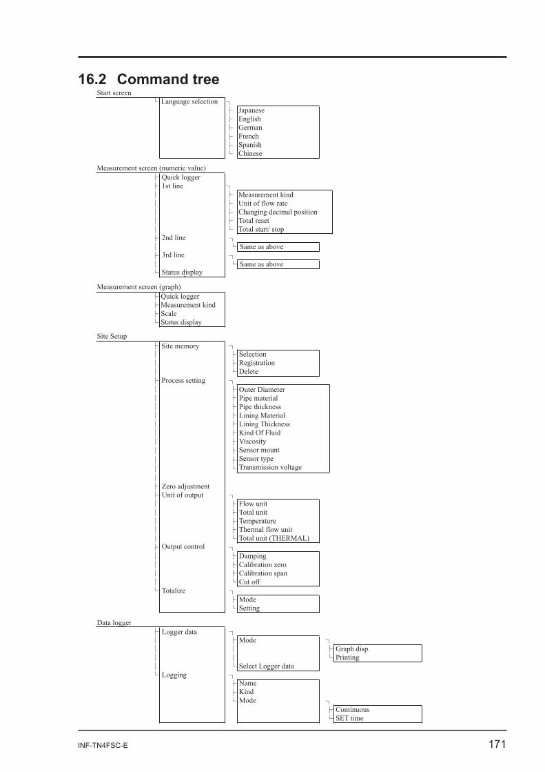
Language selection
Same as above
Same as above
Measurement screen (numeric value)
Measurement screen (graph)
Site Setup
Data logger
Site memory
Process setting
Start screen
JapaneseEnglishGermanFrench SpanishChinese
Measurement kindUnit of flow rateChanging decimal position Total resetTotal start/ stop
Quick loggerMeasurement kindScaleStatus display
SelectionRegistrationDelete
Zero adjustmentUnit of output
Output control
Totalize
Logger data
Logging
Outer DiameterPipe materialPipe thicknessLining MaterialLining ThicknessKind Of FluidViscositySensor mountSensor typeTransmission voltage
Flow unitTotal unitTemperatureThermal flow unitTotal unit (THERMAL)
DampingCalibration zeroCalibration spanCut off
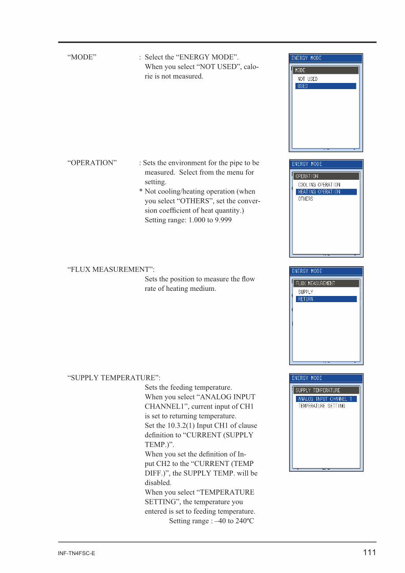
ModeSetting
NameKindMode
Graph disp.Printing
ContinuousSET time
Mode
Select Logger data
Quick logger1st line
2nd line
3rd line
Status display
172 INF-TN4FSC-E
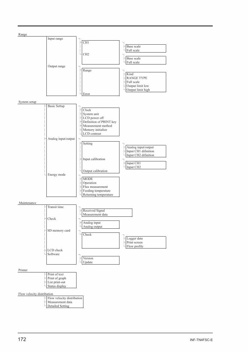
RangeInput range
CH1
CH2
Base scaleFull scale
Base scaleFull scale
KindRANGE TYPEFull scaleOutput limit lowOutput limit high
ClockSystem unitLCD power offDefinition of PRINT keyMeasurement methodMemory initializeLCD contrast
Analog input/outputInput CH1 difinitionInput CH2 difinition
Input CH1Input CH2
MODEOperationFlux measurementFeeding temperatureReturning temperature
Received SignalMeasurement data
Logger dataPrint screenFlow profile
Analog inputAnalog output
VersionUpdate
Print of textPrint of graphList print-out Status display
Flow velocity distributionMeasurement dataDetailed Setting
Printer
Flow velocity distribution
Check
Transit time
Check
SD memory card
LCD checkSoftware
Setting
Input calibration
Output calibration
System setupBasic Settup
Analog input/output
Energy mode
Maintenance
Range
Error
Output range
INF-TN4FSC-E 173
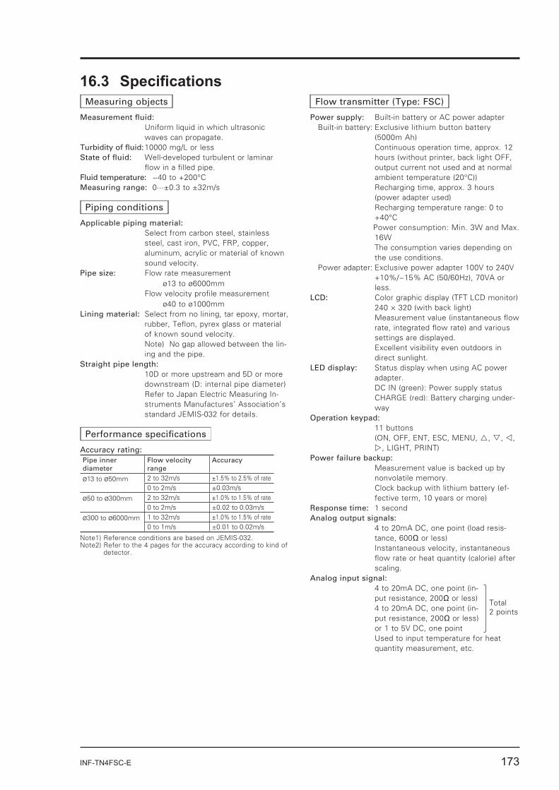
Measuring objects
Measurement fl uid: Uniform liquid in which ultrasonic
waves can propagate.Turbidity of fl uid: 10000 mg/L or lessState of fl uid: Well-developed turbulent or laminar
fl ow in a fi lled pipe.Fluid temperature: −40 to +200°CMeasuring range: 0···±0.3 to ±32m/s
Piping conditions
Applicable piping material: Select from carbon steel, stainless
steel, cast iron, PVC, FRP, copper, aluminum, acrylic or material of known sound velocity.
Pipe size: Flow rate measurement ø13 to ø6000mm
Flow velocity profi le measurement ø40 to ø1000mm
Lining material: Select from no lining, tar epoxy, mortar, rubber, Tefl on, pyrex glass or material of known sound velocity.
Note) No gap allowed between the lin-ing and the pipe.
Straight pipe length: 10D or more upstream and 5D or more
downstream (D: internal pipe diameter) Refer to Japan Electric Measuring In-
struments Manufactures’ Association’s standard JEMIS-032 for details.
Performance specifi cations
Accuracy rating: Pipe inner diameter
Flow velocity range
Accuracy
ø13 to ø50mm 2 to 32m/s ±1.5% to 2.5% of rate0 to 2m/s ±0.03m/s
ø50 to ø300mm 2 to 32m/s ±1.0% to 1.5% of rate0 to 2m/s ±0.02 to 0.03m/s
ø300 to ø6000mm 1 to 32m/s ±1.0% to 1.5% of rate0 to 1m/s ±0.01 to 0.02m/s
Note1) Reference conditions are based on JEMIS-032.Note2) Refer to the 4 pages for the accuracy according to kind of
detector.
Flow transmitter (Type: FSC)
Power supply: Built-in battery or AC power adapterBuilt-in battery: Exclusive lithium button battery
(5000m Ah) Continuous operation time, approx. 12
hours (without printer, back light OFF, output current not used and at normal ambient temperature (20°C))
Recharging time, approx. 3 hours (power adapter used)
Recharging temperature range: 0 to +40°C
Power consumption: Min. 3W and Max. 16W
The consumption varies depending on the use conditions.
Power adapter: Exclusive power adapter 100V to 240V +10%/−15% AC (50/60Hz), 70VA or less.
LCD: Color graphic display (TFT LCD monitor) 240 × 320 (with back light) Measurement value (instantaneous fl ow
rate, integrated fl ow rate) and various settings are displayed.
Excellent visibility even outdoors in direct sunlight.
LED display: Status display when using AC power adapter.
DC IN (green): Power supply status CHARGE (red): Battery charging under-
wayOperation keypad: 11 buttons (ON, OFF, ENT, ESC, MENU, , , ,
, LIGHT, PRINT)Power failure backup: Measurement value is backed up by
nonvolatile memory. Clock backup with lithium battery (ef-
fective term, 10 years or more)Response time: 1 secondAnalog output signals: 4 to 20mA DC, one point (load resis-
tance, 600 or less) Instantaneous velocity, instantaneous
fl ow rate or heat quantity (calorie) after scaling.
Analog input signal: 4 to 20mA DC, one point (in-
put resistance, 200 or less) 4 to 20mA DC, one point (in-
put resistance, 200 or less) or 1 to 5V DC, one point
Used to input temperature for heat quantity measurement, etc.
Total 2 points
174 INF-TN4FSC-E
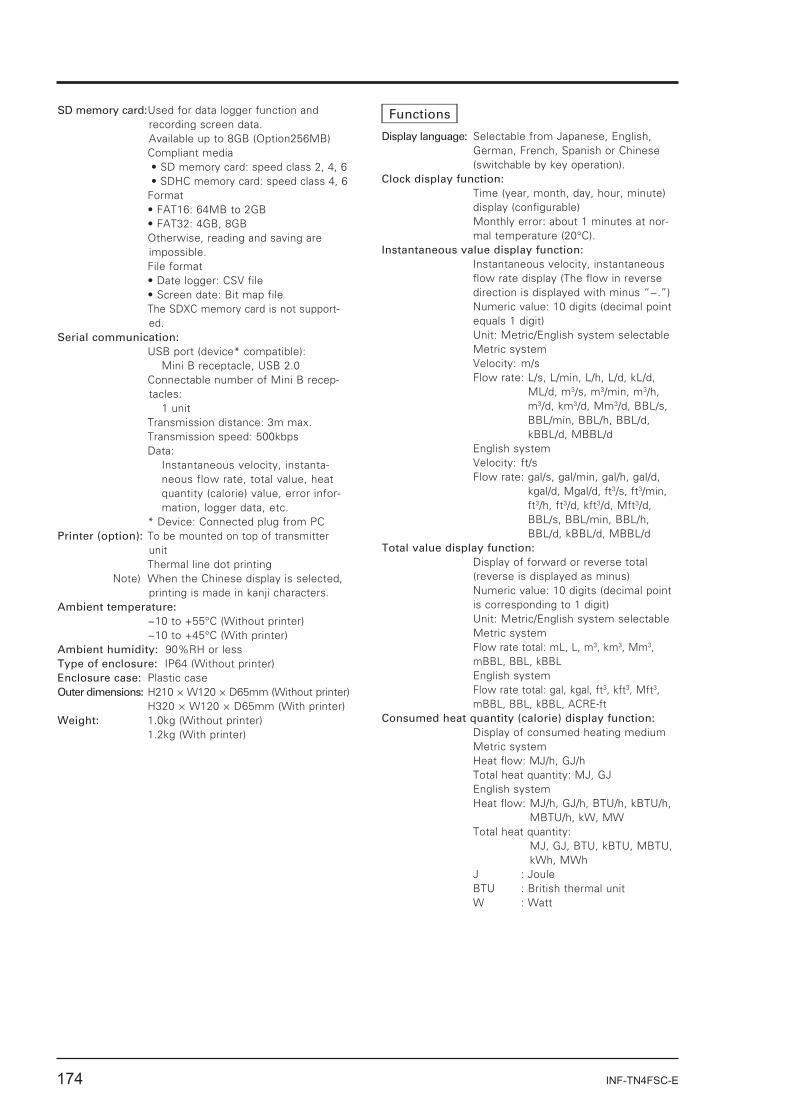
SD memory card: Used for data logger function and recording screen data.Available up to 8GB (Option256MB)
Compliant media SD memory card: speed class 2, 4, 6SDHC memory card: speed class 4, 6
Format
Otherwise, reading and saving are impossible.
File format
The SDXC memory card is not support-ed.
Serial communication: USB port (device* compatible):
Mini B receptacle, USB 2.0 Connectable number of Mini B recep-
tacles:1 unit
Transmission distance: 3m max. Transmission speed: 500kbps Data:
Instantaneous velocity, instanta-neous flow rate, total value, heat quantity (calorie) value, error infor-mation, logger data, etc.
* Device: Connected plug from PCPrinter (option): To be mounted on top of transmitter
unit Thermal line dot printing Note) When the Chinese display is selected,
printing is made in kanji characters.Ambient temperature: −10 to +55°C (Without printer) −10 to +45°C (With printer)Ambient humidity: 90%RH or lessType of enclosure: IP64 (Without printer)Enclosure case: Plastic caseOuter dimensions: H210 × W120 × D65mm (Without printer) H320 × W120 × D65mm (With printer)Weight: 1.0kg (Without printer) 1.2kg (With printer)
Functions
Display language: Selectable from Japanese, English, German, French, Spanish or Chinese (switchable by key operation).
Clock display function: Time (year, month, day, hour, minute)
display (confi gurable) Monthly error: about 1 minutes at nor-
mal temperature (20°C). Instantaneous value display function: Instantaneous velocity, instantaneous
fl ow rate display (The fl ow in reverse direction is displayed with minus “−.”)
Numeric value: 10 digits (decimal point equals 1 digit)
Unit: Metric/English system selectable Metric system Velocity: m/s
Flow rate: L/s, L/min, L/h, L/d, kL/d, ML/d, m3/s, m3/min, m3/h, m3/d, km3/d, Mm3/d, BBL/s, BBL/min, BBL/h, BBL/d, kBBL/d, MBBL/d
English system Velocity: ft/s
Flow rate: gal/s, gal/min, gal/h, gal/d, kgal/d, Mgal/d, ft3/s, ft3/min, ft3/h, ft3/d, kft3/d, Mft3/d, BBL/s, BBL/min, BBL/h, BBL/d, kBBL/d, MBBL/d
Total value display function: Display of forward or reverse total
(reverse is displayed as minus) Numeric value: 10 digits (decimal point
is corresponding to 1 digit) Unit: Metric/English system selectable Metric system Flow rate total: mL, L, m3, km3, Mm3,
mBBL, BBL, kBBL English system Flow rate total: gal, kgal, ft3, kft3, Mft3,
mBBL, BBL, kBBL, ACRE-ftConsumed heat quantity (calorie) display function: Display of consumed heating medium Metric system Heat fl ow: MJ/h, GJ/h Total heat quantity: MJ, GJ English system
Heat fl ow: MJ/h, GJ/h, BTU/h, kBTU/h, MBTU/h, kW, MW
Total heat quantity: MJ, GJ, BTU, kBTU, MBTU, kWh, MWh
J : Joule BTU : British thermal unit W : Watt
INF-TN4FSC-E 175
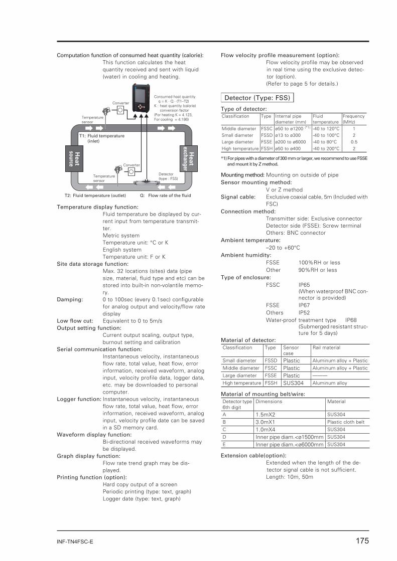
Computation function of consumed heat quantity (calorie): This function calculates the heat
quantity received and sent with liquid (water) in cooling and heating.
Heat
sou
rce
Heat
exchan
ger
Detector(type : FSS)
Temperature sensor
Temperature sensor
Consumed heat quantity q = K · Q · (T1–T2)K : heat quantity (calorie) conversion factor(For heating K = 4.123,For cooling = 4.186)
Q: Flow rate of the fluidT2: Fluid temperature (outlet)
T1: Fluid temperature (inlet)
Converter
Converter
Temperature display function: Fluid temperature be displayed by cur-
rent input from temperature transmit-ter.
Metric system Temperature unit: °C or K English system Temperature unit: F or KSite data storage function: Max. 32 locations (sites) data (pipe
size, material, fl uid type and etc) can be stored into built-in non-volantile memo-ry.
Damping: 0 to 100sec (every 0.1sec) confi gurable for analog output and velocity/flow rate display
Low fl ow cut: Equivalent to 0 to 5m/sOutput setting function: Current output scaling, output type,
burnout setting and calibrationSerial communication function: Instantaneous velocity, instantaneous
fl ow rate, total value, heat fl ow, error information, received waveform, analog input, velocity profile data, logger data, etc. may be downloaded to personal computer.
Logger function: Instantaneous velocity, instantaneous fl ow rate, total value, heat fl ow, error information, received waveform, analog input, velocity profi le date can be saved in a SD memory card.
Waveform display function: Bi-directional received waveforms may
be displayed.Graph display function: Flow rate trend graph may be dis-
played.Printing function (option): Hard copy output of a screen Periodic printing (type: text, graph) Logger date (type: text, graph)
Flow velocity profi le measurement (option): Flow velocity profi le may be observed
in real time using the exclusive detec-tor (option).
(Refer to page 5 for details.)
Detector (Type: FSS)
Type of detector:Classifi cation Type Internal pipe
diameter (mm)Fluid temperature
Frequency(MHz)
Middle diameter FSSC ø50 to ø1200 (*1) -40 to 120°C 1Small diameter FSSD ø13 to ø300 -40 to 100°C 2Large diameter FSSE ø200 to ø6000 -40 to 80°C 0.5High temperature FSSH ø50 to ø400 -40 to 200°C 2
*1) For pipes with a diameter of 300 mm or larger, we recommend to use FSSE and mount it by Z method.
Mounting method: Mounting on outside of pipeSensor mounting method: V or Z methodSignal cable: Exclusive coaxial cable, 5m (Included with
FSC)Connection method: Transmitter side: Exclusive connector Detector side (FSSE): Screw terminal Others: BNC connectorAmbient temperature: –20 to +60°CAmbient humidity: FSSE 100%RH or less Other 90%RH or lessType of enclosure: FSSC IP65 (When waterproof BNC con-
nector is provided) FSSE IP67 Others IP52 Water-proof treatment type IP68 (Submerged resistant struc-
ture for 5 days)Material of detector:Classifi cation Type Sensor
caseRail material
Small diameter FSSD Plastic Aluminum alloy + Plastic
Middle diameter FSSC Plastic Aluminum alloy + Plastic
Large diameter FSSE Plastic ———
High temperature FSSH SUS304 Aluminum alloy
Material of mounting belt/wire:Detector type6th digit
Dimensions Material
A 1.5mX2 SUS304
B 3.0mX1 Plastic cloth belt
C 1.0mX4 SUS304
D Inner pipe diam.<ø1500mm SUS304
E Inner pipe diam.<ø6000mm SUS304
Extension cable(option): Extended when the length of the de-
tector signal cable is not suffi cient. Length: 10m, 50m
176 INF-TN4FSC-E
FLOW VELOCITY PROFILE DISPLAY FUNCTION (OPTION)
Pulse Doppler method enables the analysis and display of the fl ow velocity profi le in real time. The results can be used to decide the appropriate measurement location, for fl ow diagnosis, and laboratory test.
SPECIFICATIONSMeasuring fl uid: Uniform liquid in which ultrasonic
waves can propagate.Turbidity of fl uid: Axisymmetric fl ow in a fi lled pipe.Fluid temperature: −40 to +100°C (FSDP2) −40 to +80°C (FSDP1,FSDP0)Air bubble quantity: 0.02 to 15vol% (Velocity is 1m/s)Pipe size: Small type sensor : ø40 to ø200mm Middle type sensor :ø100 to ø400mm Large type sensor :ø200 to ø1000mmMeasurement range: 0 to ±0.3 … ±Maximum Velocity (de-
pending on the pipe diameter) Refer to chart, page 145. Note) This function is to observe fl ow
velocity profi le, and it may be different from actual fl ow rate.
DETECTOR FOR FLOW VELOCITY PROFILE MEASUREMENT (TYPE: FSDP)Mounting method: on outside of existing pipeAmbient temperature: −20 to +80°CAmbient humidity: 100% RH or lessEnclosure: IP67 (waterproof BNC connector
required.)Material: Sensor housing: PBT Guide frame: Aluminum alloy
Mounting belt: Plastic cloth or stain-less
EU Directive Compliance
EMC (2014/30/EU) EN 61326-1 (Table 2) EN 55011 (Group 1 Class A) EN 61000-3-2 (Class A) EN 61000-3-3 EN 61326-2-3 RoHS (2011/65/EU) EN 50581
INF-TN4FSC-E 177
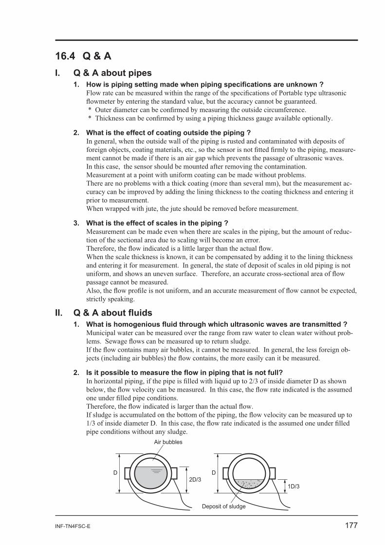
-
-
-
-
-
D
1D/3
D2D/3
Deposit of sludge
Air bubbles
178 INF-TN4FSC-E
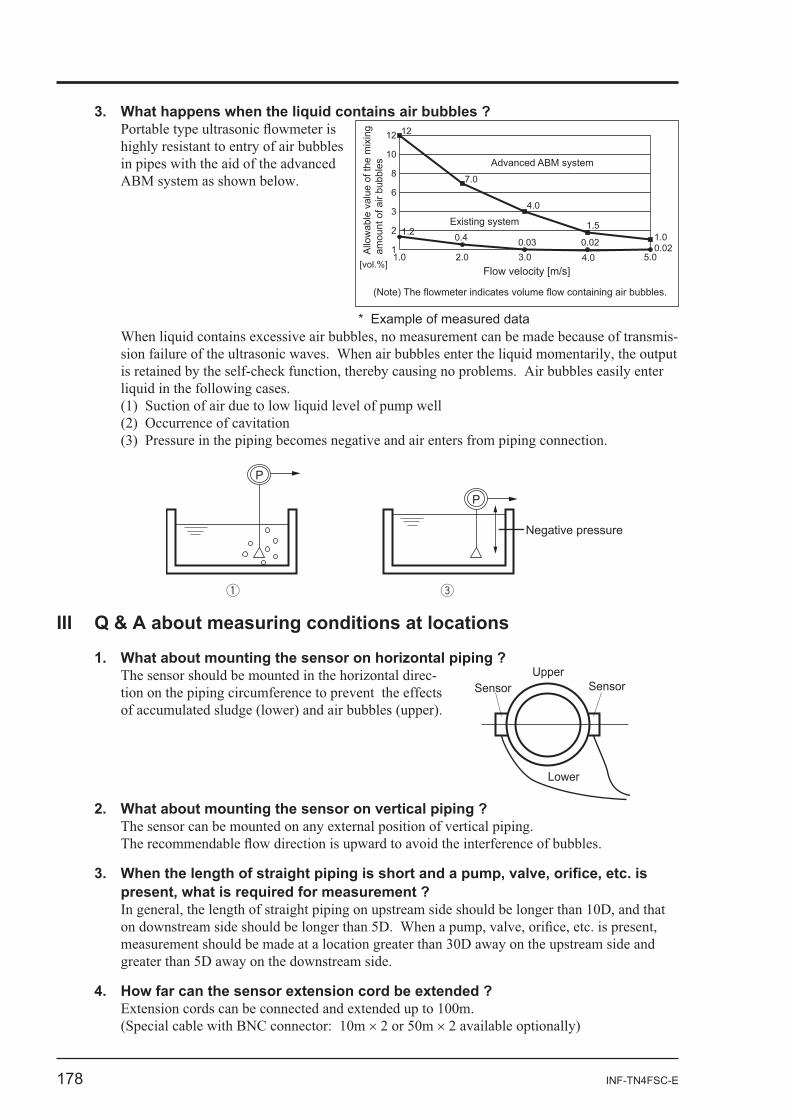
is
in pipes with the aid of the advanced
-
P
P
Negative pressure
1.0 2.0 3.0 4.0 5.01
2
3
6
8
10
12 12
7.0
4.0
1.51.00.020.020.030.41.2
Advanced ABM system
Existing system
(Note) The flowmeter indicates volume flow containing air bubbles.
[vol.%]Flow velocity [m/s]
* Example of measured data
Allo
wab
le v
alue
of t
he m
ixin
g am
ount
of a
ir bu
bble
s
- UpperSensor Sensor
Lower
INF-TN4FSC-E 179
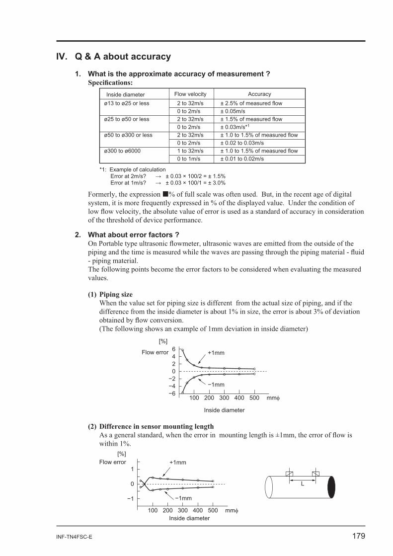
(1) Piping size
100
6
0
500
[%]
300 mm
+1mm
Inside diameter
Flow error
L
100
0
1
400 500
[%]
300 mm
+1mm
200Inside diameter
Flow error
Flow velocity Inside diameter
*1: Example of calculation Error at 2m/s Error at 1m/s
ø ø
ø ø
ø ø
ø ø
of measured flow
of measured flow*1
of measured flow
of measured flow
Accuracy
180 INF-TN4FSC-E
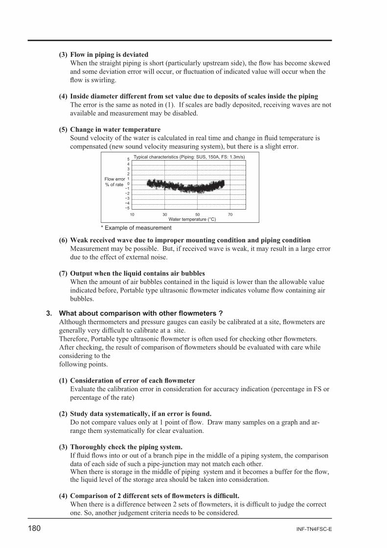
(3) Flow in piping is deviated
% of rate
10 30 50 70
01
3
5
Flow error
Water temperature (°C)
Typical characteristics (Piping: SUS, 150A, FS: 1.3m/s)
* Example of measurement
-
INF-TN4FSC-E 181
V. Others
1. Life span of LCD -
2. Printer roll sheet
3
182 INF-TN4FSC-E
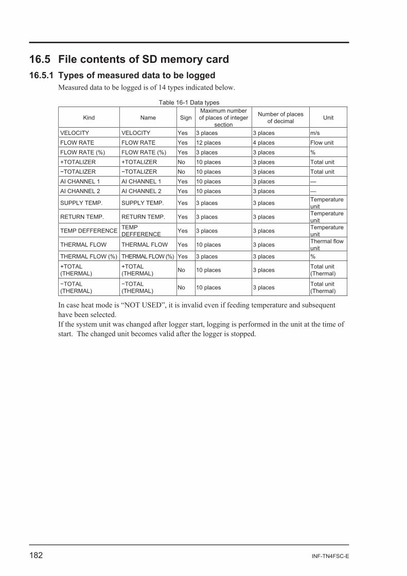
Table 16-1 Data types
Kind Name SignMaximum number of places of integer
section
Number of places of decimal Unit
VELOCITY VELOCITY Yes 3 places 3 places m/s
FLOW RATE FLOW RATE Yes 12 places 4 places Flow unit
FLOW RATE (%) FLOW RATE (%) Yes 3 places 3 places %
+TOTALIZER +TOTALIZER No 10 places 3 places Total unit
No 10 places 3 places Total unit
AI CHANNEL 1 AI CHANNEL 1 Yes 10 places 3 places —
AI CHANNEL 2 AI CHANNEL 2 Yes 10 places 3 places —
SUPPLY TEMP. SUPPLY TEMP. Yes 3 places 3 places Temperature unit
RETURN TEMP. RETURN TEMP. Yes 3 places 3 places Temperature unit
TEMP DEFFERENCE TEMPDEFFERENCE Yes 3 places 3 places Temperature
unit
THERMAL FLOW THERMAL FLOW Yes 10 places 3 places unit
THERMAL FLOW (%) THERMAL FLOW (%) Yes 3 places 3 places %
+TOTAL (THERMAL)
+TOTAL (THERMAL) No 10 places 3 places Total unit
(Thermal)
(THERMAL)
(THERMAL) No 10 places 3 places Total unit
(Thermal)
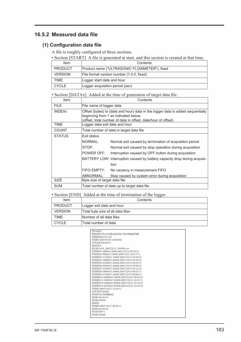
INF-TN4FSC-E 183
Item ContentsPRODUCT Product name ("ULTRASONIC FLOWMETERVERSIONTIME Logger start date and hourCYCLE Logger acquisition period (sec)
Item ContentsFILE File name of logger dataINDEXx Offset (bytes) to (date and hour) data in the logger data is added sequentially
beginning from 1 as indicated below.(offset, total number of data in offset, date/hour of offset)
TIME Logger data exit date and hourCOUNTSTATUS Exit status
NORMAL: Normal exit caused by termination of acquisition periodSTOP: Normal exit caused by stop operation during acquisitionPOWER OFF: Interruption caused by OFF button during acquisitionBATTERY LOW: Interruption caused by battery capacity drop during acquisi-
tionFIFO EMPTY: No vacancy in measurement FIFOABNORMAL: Stop caused by system error during acquisition
SIZESUM
Item ContentsPRODUCT Logger exit date and hourVERSIONTIMECYCLE Total number of data
[START]PRODUCT=ULTRASONIC FLOWMETERVERSION=V1.0.0TIME=2007/01/01 00:00:00CYCLE=00:00:01[DATA1]FILE=AAA_20071214_193032.csvINDEX1=490047,5000,2007/12/14 20:53:51INDEX2=980047,10000,2007/12/14 22:17:11INDEX3=1470047,15000,2007/12/14 23:40:31INDEX4=1960047,20000,2007/12/15 01:03:51INDEX5=2450047,25000,2007/12/15 02:27:11INDEX6=2940047,30000,2007/12/15 03:50:31INDEX7=3430047,35000,2007/12/15 05:13:51INDEX8=3920047,40000,2007/12/15 06:37:11INDEX9=4410047,45000,2007/12/15 08:00:31INDEX10=4900047,50000,2007/12/15 09:23:51INDEX11=5390047,55000,2007/12/15 10:47:11INDEX12=5880047,60000,2007/12/15 12:10:31INDEX13=6370047,65000,2007/12/15 13:33:51TIME=2007/12/15 13:42:11COUNT=65500STATUS=NORMALSIZE=6419145SUM=65500[END]TIME=2007/12/17 09:52:11SIZE=6419145FCOUNT=1SUM=65500
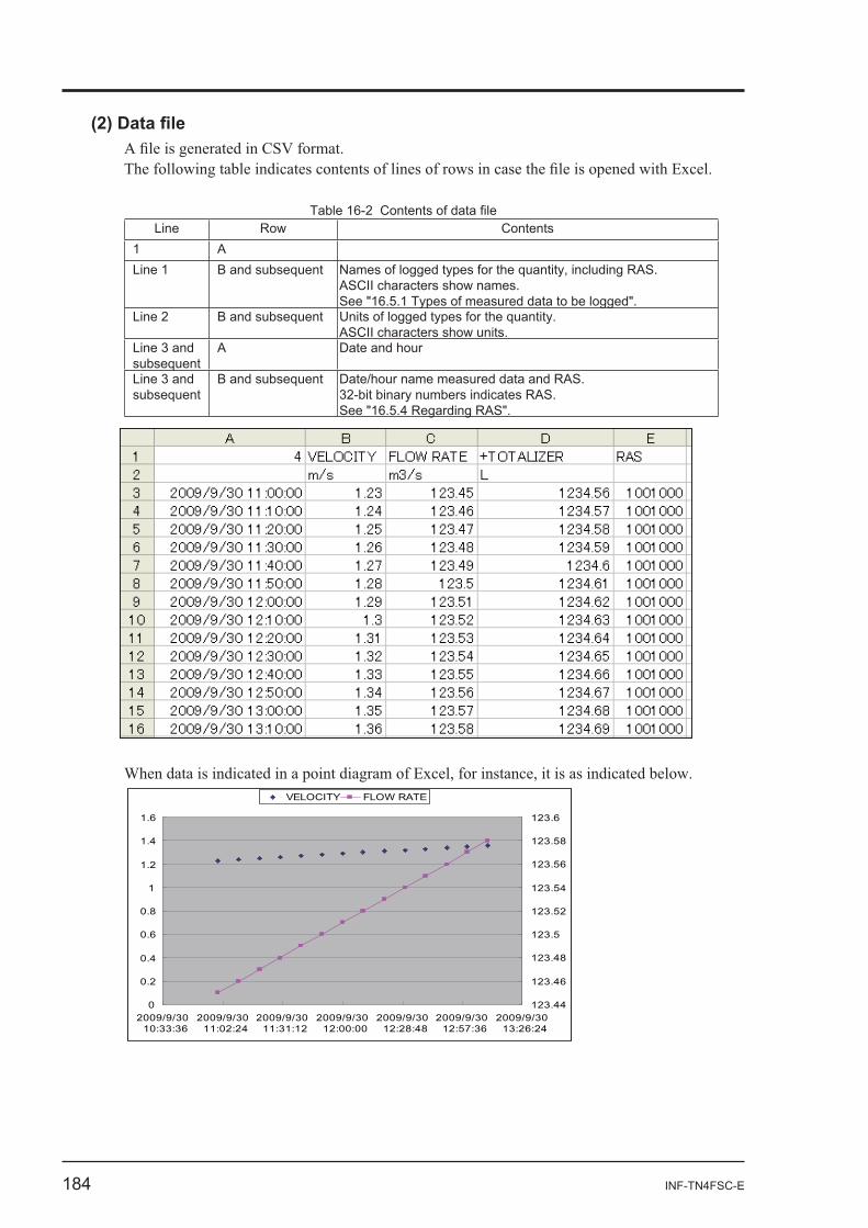
184 INF-TN4FSC-E
Table 16-2 Line Row Contents
1 ALine 1 B and subsequent Names of logged types for the quantity, including RAS.
ASCII characters show names.See "16.5.1 Types of measured data to be logged".
Line 2 B and subsequent Units of logged types for the quantity.ASCII characters show units.
Line 3 and subsequent
A Date and hour
Line 3 and subsequent
B and subsequent Date/hour name measured data and RAS.32-bit binary numbers indicates RAS.See "16.5.4 Regarding RAS".
0
0.2
0.4
0.6
0.8
1
1.2
1.4
1.6
2009/9/3010:33:36
2009/9/3011:02:24
2009/9/3011:31:12
2009/9/3012:00:00
2009/9/3012:28:48
2009/9/3012:57:36
2009/9/3013:26:24
123.44
123.46
123.48
123.5
123.52
123.54
123.56
123.58
123.6
VELOCITY FLOW RATE
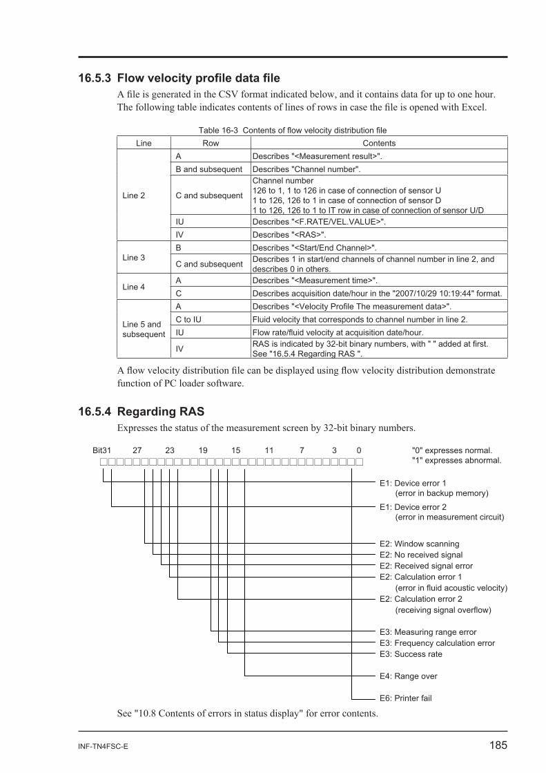
INF-TN4FSC-E 185
Table 16-3 Line Row Contents
Line 2
A Describes "<Measurement result>".B and subsequent Describes "Channel number".
C and subsequent
Channel number126 to 1, 1 to 126 in case of connection of sensor U1 to 126, 126 to 1 in case of connection of sensor D1 to 126, 126 to 1 to IT row in case of connection of sensor U/D
IU Describes "<F.RATE/VEL.VALUE>".IV Describes "<RAS>".
Line 3B Describes "<Start/End Channel>".
C and subsequent Describes 1 in start/end channels of channel number in line 2, and describes 0 in others.
Line 4A Describes "<Measurement time>".C Describes acquisition date/hour in the "2007/10/29 10:19:44" format.
Line 5 and subsequent
AC to IU Fluid velocity that corresponds to channel number in line 2.IU
IV See "16.5.4 Regarding RAS ".
16.5.4 Regarding RAS
Bit31 0371115192327 "0" expresses normal."1" expresses abnormal. □□□□□□□□□□□□□□□□□□□□□□□□□□□□□□□□
E1: Device error 1 (error in backup memory)
E1: Device error 2 (error in measurement circuit)
E2: Window scanning E2: No received signal E2: Received signal error E2: Calculation error 1
(error in fluid acoustic velocity)E2: Calculation error 2
(receiving signal overflow)
E3: Measuring range error E3: Frequency calculation error E3: Success rate
E4: Range over
E6: Printer fail

www.fujielectric.com
Instrumentation & Sensors Planning Dept.Gate City Ohsaki, East Tower, 11-2, Osaki 1-chome, Shinagawa-ku, Tokyo 141-0032, japanPhone: +81-3-5435-7021 Fax: +81-3-5435-7475www.fujielectric.com/products/instruments/