Embed Size (px)
Citation preview
MEH400a
FUJI ELECTRIC INVERTERS
Great performance in a compactWelcome to the next generationof low-noise Inverters
S E L E C T I O NG U I D E
Advanced Products Supported byCuttingedge Technology
Quality and High-Performance Line Up
� ������� � �� ������ ���� �������� �������� ����� ��� �������� ������������ �� ����� ��������� � ����� ��� ����� ���� ����� ������ ���� � �� �� �������� �������� � �������� ���������� ���������� �� ��� ��� ���� ����������
� �� ���������� ���� ����� ����� ����� ��� �� ��������� ����� ����� ! ���������� �������"� # ��� ����� � ��������$�������� ������������ %������� ���������� ���� �������� !���� �� �&#'"� ������� ��� �( ���������� )������ �������� ������ ��� ���� ������� �������� ��������� �������� ����������$��������� ��������
� ���� � ����� ���� �� ���������� �������� �� ����� �������� � ����� � ����������� � ����� ��� ������������ ���������� �� ��� ������� ��� ������ *�������� �� ��������� ������� ��� � ������������������ ��������� +������� ������� ,��-����� ������� ������ ���� �� ������� ���������� �-��� ��� �� ���� ���-����� �������.
� /���� �� �������� ����� �� ������� ��������� ������0 �.�. ��� ���� ��-�� ���0 ������� �� ������������0 ��� ���� � �������� �������.� �� ��� ���� ������������� ������� ��� �� &*1����� ������� ��� �������� �� ��������� ���� ����� ��.� ������������ ������ �� �������.
� ������ ������ ������� ��� ���� ������ �������� /�� ���� ������ ��� ���� ��� ����������� +���������� �� �� ������� �� �� �� �������� ��� �-��� ���� '���������� � �� ���������� ������ ��� ��� �����������
� ���������������� ��������� 2�� �( � ����������� 1������� ����������� �� �������� ��-�� ��� ��-����� ���� �-��� ��� ��� �� ���� ��� �� ��.
� 3����� �������� ��������� ��� ���� � ��������� �������� � �� ����� 0 &*1 ����� �������0 ������ � ��������������0 ��� ��-����� �� � ������ � �� ������� � ��� ������ � �� �����.
� �������� �� ����0 �� ��0 ��� ��� ����������. �� #' �������������� �� �������� � ������ ��� �� ��� ����������� �� ��� �� ���� ������� �� �� ������������������������ ��������.
� ������������ ������ �� �������.
� �� ��� �������0 �� ��� ������ '���������� � ��������� �-��� ���0 ��� � ��������� � ��������� ��������� 4� ��� ��� �� �������� �-������ �� �������� ��(������ ,���� � ������� �� ��� �( �������� ����� � ����������
� �������� ����������$��������� ��������� *���������� 5�4 �� �� ��� �������� '��� ��� � ��� ���������
� #��������� ����� ����6 &� ����� �����0��������� ����� �����0 ���� �� ��-�� ����������0 ��� 3$� ������ * ����� ����� ���� � ������� ������� ��� ������������ !����� �����"� * ����� ���������� �� ������ �������� 5����� �� � ��% ������� !����"� ��� � ����� � � ����� ���� ����� !1������� ����6 78�����"
� 3����� �������� ��� ��� ���� � ��� ����� ������������� �������� �������� � �� ���(� ������� �������� ���!9::(;"::(;9778(;6 '����� ,�<�� ����� ��� �������� ������ ���� ��=� ������ ' ������� �� >)� 1��������� !�������"� * ����� ���������� � �� ������ ����� � ����
The highest standards of control and performance in its class
Optimum performance for traversing conveyors
The ideal functions to serve a multiplicity of needs for small-capacity inverters
Mini / Multi
3�������� �������� � ���
'���� �����
>������������
'������
�� �
�����
'������� ��������
/����-��
:88 �
?88�$ ��
:88@
8
■ With speed feedback
/��6 � ���
/��6 /����
�� ����� <��� ����� ��������� ������0 ���������� �������� ����.
�� ����� <��� ����� ��������� �� ����������0��� � ��������� �������� �� � �����.
�����
'������� ��������8
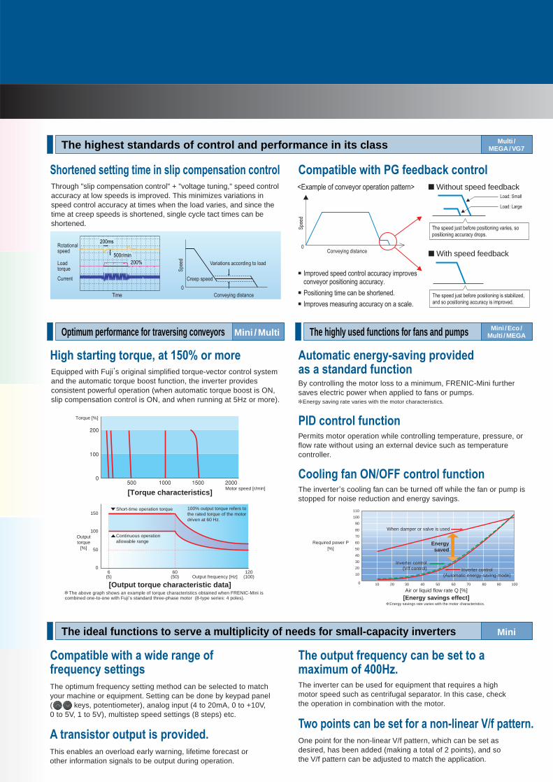
Through "slip compensation control" + "voltage tuning," speed control accuracy at low speeds is improved. This minimizes variations in speed control accuracy at times when the load varies, and since the time at creep speeds is shortened, single cycle tact times can be shortened.
��������� ������ �� � �� ��� �� �������� �������
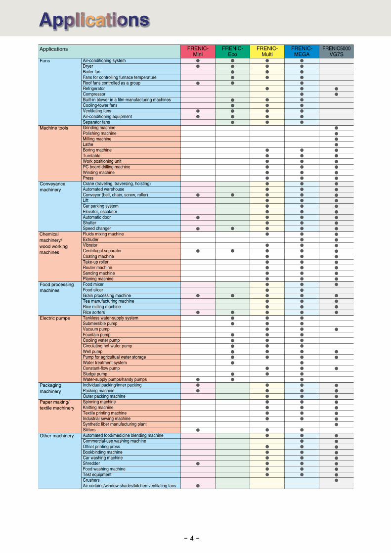
Equipped with Fuji,s original simplified torque-vector control system
and the automatic torque boost function, the inverter provides consistent powerful operation (when automatic torque boost is ON, slip compensation control is ON, and when running at 5Hz or more).
���� ������� ������� �� ���� �� ���
�� ������� ���� �� ������� �������
■ Without speed feedbackA��� ��� � ������ ������� �������B
■ * ����� ����� ����� �������� � ����������� ��������� ��������.
■ &�������� �� � ��� �� �������.
■ * ����� �������� �������� � � �����.
Motor speed [r/min]
Torque [%]
0
100
50
60(50)
120(100)Output frequency [Hz]
Short-time operation torque
Continuous operation allowable range
Outputtorque
[%]
150
6(5)
100% output torque refers tothe rated torque of the motordriven at 60 Hz.
[Output torque characteristic data]
[Torque characteristics]
The above graph shows an example of torque characteristics obtained when FRENIC-Mini iscombined one-to-one with Fuji
,s standard three-phase motor (8-type series: 4 poles).
Multi /
MEGA / VG7
The highly used functions for fans and pumps
Mini
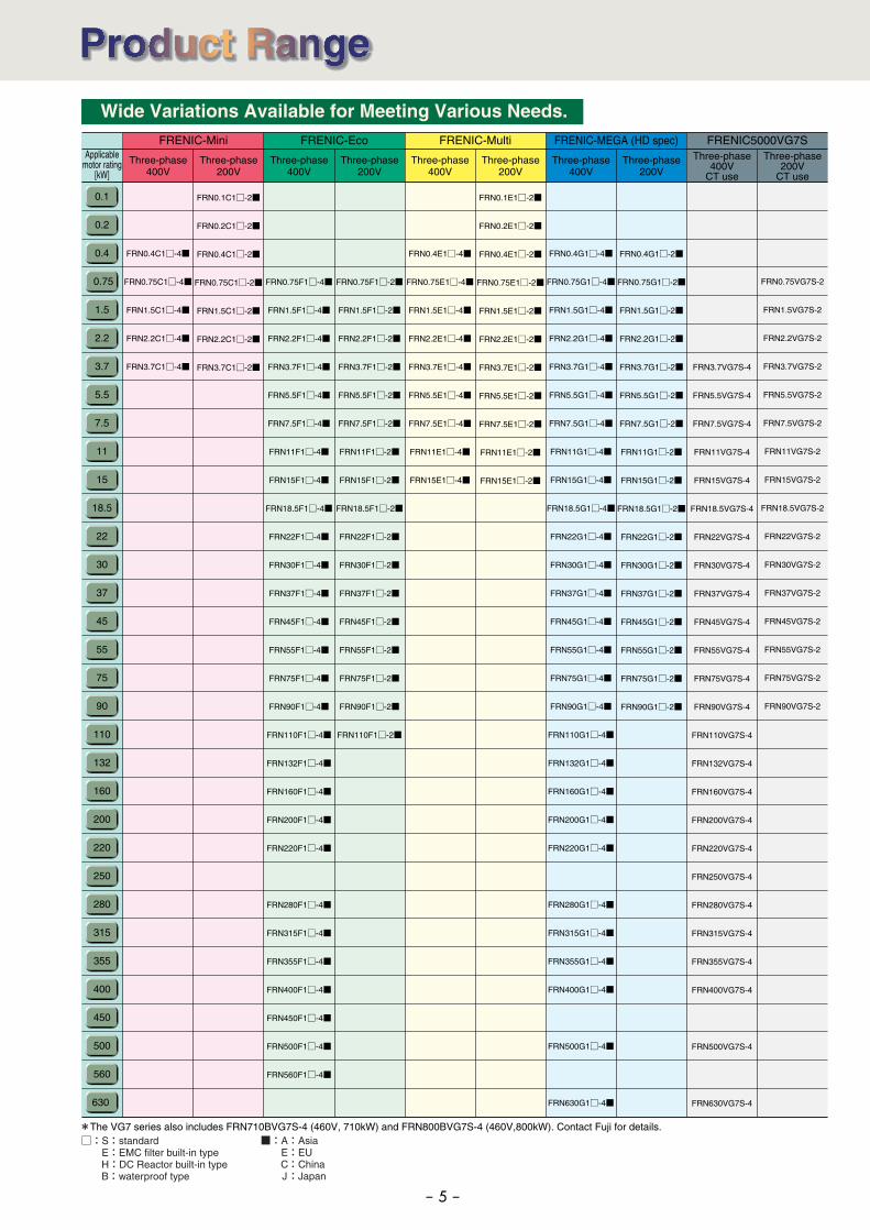
!��� ���� �����"#�$��� ���$����� � ������� ��������By controlling the motor loss to a minimum, FRENIC-Mini further saves electric power when applied to fans or pumps.
������� ��� %&'%(( ������� ��������The inverter
,s cooling fan can be turned off while the fan or pump is
stopped for noise reduction and energy savings.
�)* ������� ��������Permits motor operation while controlling temperature, pressure, or flow rate without using an external device such as temperature controller.
Energy saving rate varies with the motor characteristics.
Required power P[%]
Air or liquid flow rate Q [%][Energy savings effect]
Energy savings rate varies with the motor characteristics.
110
90
80
70
60
50
40
30
20
10
0 2010 30 40 50 60 70 80 90 100
100
! �������� ������ � ���$����+
This enables an overload early warning, lifetime forecast or other information signals to be output during operation.
�� ������� ���� � ���� ����� ����������" ������
The optimum frequency setting method can be selected to match your machine or equipment. Setting can be done by keypad panel ( keys, potentiometer), analog input (4 to 20mA, 0 to +10V, 0 to 5V, 1 to 5V), multistep speed settings (8 steps) etc.
,�� ����� ��� �� �� ��� � ���#������ -'� �������+One point for the non-linear V/f pattern, which can be set as desired, has been added (making a total of 2 points), and so the V/f pattern can be adjusted to match the application.
,�� ������ ��������" ��� �� �� �� � �.� � �� /���0+The inverter can be used for equipment that requires a high motor speed such as centrifugal separator. In this case, check the operation in combination with the motor.
When damper or valve is used
Inverter control(V/f control) Inverter control
(Automatic energy-saving mode)
Energy
saved
Mini / Eco /
Multi / MEGA
Other machinery
Chemical machinery/wood workingmachines
Air-conditioning system DryerBoiler fan Fans for controlling furnace temperatureRoof fans controlled as a groupRefrigerator CompressorBuilt-in blower in a film-manufacturing machinesCooling-tower fans Ventilating fansAir-conditioning equipmentSeparator fans Grinding machinePolishing machine Milling machineLatheBoring machine Turntable Work positioning unitPC board drilling machineWinding machinePress Crane (traveling, traversing, hoisting)Automated warehouseConveyor (belt, chain, screw, roller) LiftCar parking system Elevator, escalator Automatic doorShutter Speed changer Fluids mixing machine Extruder VibratorCentrifugal separator Coating machine Take-up roller Router machine Sanding machine Planing machine Food mixerFood slicer Grain processing machine Tea manufacturing machineRice milling machine Rice sortersTankless water-supply systemSubmersible pump Vacuum pump Fountain pump Cooling water pumpCirculating hot water pump Well pump Pump for agricultual water storage Water treatment systemConstant-flow pump Sludge pumpWater-supply pumps/handy pumps Individual packing/inner packing Packing machine Outer packing machine Spinning machineKnitting machine Textile printing machine Industrial sewing machine Synthetic fiber manufacturing plantSlitters Automated food/medicine blending machine Commercial-use washing machine Offset printing press Bookbinding machine Car washing machine Shredder Food washing machine Test equipmentCrushersAir curtains/window shades/kitchen ventilating fans
Fans
Machine tools
Conveyance machinery
Food processing machines
Electric pumps
Packaging machinery
Paper making/textile machinery
FRENIC-MEGA
FRENIC-Multi
FRENIC5000VG7S
FRENIC-Eco
Applications FRENIC-Mini
- 4 -
Three-phase200V
Three-phase400V
Three-phase200V
Three-phase400V
Three-phase200V
Three-phase400V
Three-phase200V
Three-phase400V
Three-phase200V
CT use
Three-phase400V
CT use
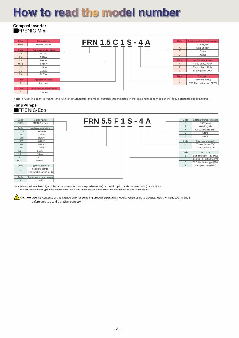
FRENIC-Mini FRENIC-MEGA (HD spec)FRENIC-Eco FRENIC-Multi FRENIC5000VG7S
Wide Variations Available for Meeting Various Needs.
0.1
0.2
0.4
0.75
1.5
2.2
3.7
5.5
7.5
11
15
18.5
22
30
37
45
55
75
90
110
132
160
200
220
250
280
315
355
400
450
500
560
630
FRN0.1C1□-2■
FRN0.2C1□-2■
FRN0.4C1□-2■
FRN0.75C1□-2■
FRN1.5C1□-2■
FRN2.2C1□-2■
FRN3.7C1□-2■
FRN0.4C1□-4■
FRN0.75C1□-4■
FRN1.5C1□-4■
FRN2.2C1□-4■
FRN3.7C1□-4■
FRN0.4G1□-2■
FRN0.75G1□-2■
FRN1.5G1□-2■
FRN2.2G1□-2■
FRN3.7G1□-2■
FRN5.5G1□-2■
FRN7.5G1□-2■
FRN11G1□-2■
FRN15G1□-2■
FRN18.5G1□-2■
FRN22G1□-2■
FRN30G1□-2■
FRN37G1□-2■
FRN45G1□-2■
FRN55G1□-2■
FRN75G1□-2■
FRN90G1□-2■
FRN0.4G1□-4■
FRN0.75G1□-4■
FRN1.5G1□-4■
FRN2.2G1□-4■
FRN3.7G1□-4■
FRN5.5G1□-4■
FRN7.5G1□-4■
FRN11G1□-4■
FRN15G1□-4■
FRN18.5G1□-4■
FRN22G1□-4■
FRN30G1□-4■
FRN37G1□-4■
FRN45G1□-4■
FRN55G1□-4■
FRN75G1□-4■
FRN90G1□-4■
FRN110G1□-4■
FRN132G1□-4■
FRN160G1□-4■
FRN200G1□-4■
FRN220G1□-4■
FRN280G1□-4■
FRN315G1□-4■
FRN355G1□-4■
FRN400G1□-4■
FRN500G1□-4■
FRN630G1□-4■
FRN0.75F1□-2■
FRN1.5F1□-2■
FRN2.2F1□-2■
FRN3.7F1□-2■
FRN5.5F1□-2■
FRN7.5F1□-2■
FRN11F1□-2■
FRN15F1□-2■
FRN18.5F1□-2■
FRN22F1□-2■
FRN30F1□-2■
FRN37F1□-2■
FRN45F1□-2■
FRN55F1□-2■
FRN75F1□-2■
FRN90F1□-2■
FRN110F1□-2■
FRN0.75F1□-4■
FRN1.5F1□-4■
FRN2.2F1□-4■
FRN3.7F1□-4■
FRN5.5F1□-4■
FRN7.5F1□-4■
FRN11F1□-4■
FRN15F1□-4■
FRN18.5F1□-4■
FRN22F1□-4■
FRN30F1□-4■
FRN37F1□-4■
FRN45F1□-4■
FRN55F1□-4■
FRN75F1□-4■
FRN90F1□-4■
FRN110F1□-4■
FRN132F1□-4■
FRN160F1□-4■
FRN200F1□-4■
FRN220F1□-4■
FRN280F1□-4■
FRN315F1□-4■
FRN355F1□-4■
FRN400F1□-4■
FRN450F1□-4■
FRN500F1□-4■
FRN560F1□-4■
FRN0.1E1□-2■
FRN0.2E1□-2■
FRN0.4E1□-2■
FRN0.75E1□-2■
FRN1.5E1□-2■
FRN2.2E1□-2■
FRN3.7E1□-2■
FRN5.5E1□-2■
FRN7.5E1□-2■
FRN11E1□-2■
FRN15E1□-2■
FRN0.4E1□-4■
FRN0.75E1□-4■
FRN1.5E1□-4■
FRN2.2E1□-4■
FRN3.7E1□-4■
FRN5.5E1□-4■
FRN7.5E1□-4■
FRN11E1□-4■
FRN15E1□-4■
FRN0.75VG7S-2
FRN1.5VG7S-2
FRN2.2VG7S-2
FRN3.7VG7S-2
FRN5.5VG7S-2
FRN7.5VG7S-2
FRN11VG7S-2
FRN15VG7S-2
FRN18.5VG7S-2
FRN22VG7S-2
FRN30VG7S-2
FRN37VG7S-2
FRN45VG7S-2
FRN55VG7S-2
FRN75VG7S-2
FRN90VG7S-2
FRN3.7VG7S-4
FRN5.5VG7S-4
FRN7.5VG7S-4
FRN11VG7S-4
FRN15VG7S-4
FRN18.5VG7S-4
FRN22VG7S-4
FRN30VG7S-4
FRN37VG7S-4
FRN45VG7S-4
FRN55VG7S-4
FRN75VG7S-4
FRN90VG7S-4
FRN110VG7S-4
FRN132VG7S-4
FRN160VG7S-4
FRN200VG7S-4
FRN220VG7S-4
FRN250VG7S-4
FRN280VG7S-4
FRN315VG7S-4
FRN355VG7S-4
FRN400VG7S-4
FRN500VG7S-4
FRN630VG7S-4
*The VG7 series also includes FRN710BVG7S-4 (460V, 710kW) and FRN800BVG7S-4 (460V,800kW). Contact Fuji for details.
Applicablemotor rating
[kW]
□:S:standard E:EMC filter built-in type H:DC Reactor built-in type B:waterproof type
■:A:AsiaE:EUC:ChinaJ:Japan
- 5 -
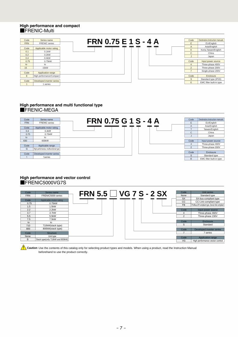
Compact inverter■FRENIC-Mini
Code
FRN
Series name
FRENIC series
Code
E
A
C
J
Destination,Instruction manuals
EU/English
Asia/ English
China
Japan
Code
4
2
7
Input power source
Three-phase 400V
Three-phase 200V
Single-phase 200V
Code
0.1
0.2
0.4
0.75
1.5
2.2
3.7
Applicable motor rating
0.1kW
0.2kW
0.4kW
0.75kW
1.5kW
2.2kW
3.7kW
Code
C
Application range
Compact
Code
1
Developed inverter series
1 series
Code
S
E
Enclosure
Standard (IP20)
EMC filter built-in type (IP20)
Fan&Pumps■FRENIC-Eco
Caution Use the contents of this catalog only for selecting product types and models. When using a product, read the Instruction Manualbeforehand to use the product correctly.
Code
FRN
Series name
FRENIC series
Code
E
A
K
C
J
Destination,Instruction manualsEU/English
Asia/English
Koria,Taiwan/English
China
Japan
Code
S
H
E
B
Structure
Standard type(IP20/IP00)
DC REACTOR built-in type(IP20)
EMC filter built-in type(IP00)
Waterproof type(IP54)
Code
4
2
Input power supply
Three-phase 400V
Three-phase 200V
Code Applicable motor rating
0.75
1.5
2.2
3.7
5.5
7.5
11
15
560
0.75kW
1.5kW
2.2kW
3.7kW
5.5kW
7.5kW
11kW
15kW
560kW
Code
F
Application rangeFans and pumps
(For variable torque load)
Code
1
Developed inverter series
1 series
to to
Note: When the lower three digits of the model number indicate a keypad (standard), no built-in option, and screw terminals (standard), the inverter is a standard type in the above model list. There may be some nonstandard models that we cannot manufacture.
FRN 1.5 C 1 S - 4 A
Note) If "Built-in option" is "None" and "Brake" is "Standard", the model numbers are indicated in the same format as those of the above standard specifications.
FRN 5.5 F 1 S - 4 A
- 6 -
FRN 5.5 □ VG 7 S - 2 SX CodeNoneSXCCFB
Unit seriesStandard type
SX-bus-compliant typeCC-Link-compliant type
Profibus-DP-compliant type, Device Net compliant
CodeFRN
Series nameFRENIC5000 series
CodeVG
Application rangeHigh performance vector control
Code7
Developed inverter series7 series
Code42
Input power sourceThree-phase 460VThree-phase 230V
CodeS
EnclosureStandard
Code Applicable motor rating0.751.52.23.75.57.5
710 800
0.75kW1.5kW2.2kW3.7kW5.5kW7.5kW
710kW(stack type)800kW(stack type)
Code Structure None B
Unit typeStack type(only 710kW and 800kW)
High performance and compact■FRENIC-Multi
High performance and vector control■FRENIC5000VG7S
toto
FRN 0.75 E 1 S - 4 A
High performance and multi functional type■FRENIC-MEGA
FRN 0.75 G 1 S - 4 A
Caution Use the contents of this catalog only for selecting product types and models. When using a product, read the Instruction Manualbeforehand to use the product correctly.
Code
FRN
Series name
FRENIC series
Code
E
A
K
C
J
Destination,Instruction manualsEU/English
Asia/English
Koria,Taiwan/English
China
Japan
Code Applicable motor rating
0.1
0.2
0.4
0.75
15
0.1kW
0.2kW
0.4kW
0.75kW
15kW
Code
4
2
7
Input power source
Three-phase 400V
Three-phase 200V
Single-phase 200V
Code
1
Developed inverter series
1 series
Code
E
Application range
High performance/Compact
to to
Code
S
E
Enclosure
Standard type (IP20)
EMC filter built-in type
Code
FRN
Series name
FRENIC series
Code
E
A
T
C
J
Destination,Instruction manualsEU/English
Asia/English
Taiwan/English
China
Japan
Code
S
E
Enclosure
Standard type
EMC filter built-in type
Code
4
2
Input power source
Three-phase 400V
Three-phase 200V
Code Applicable motor rating
0.4
0.75
630
0.4kW
0.75kW
630kW
Code
G
Applicable range
High performance, multifunctional type
Code
1
Developed inverter series
1series
to to
- 7 -
- 8 -
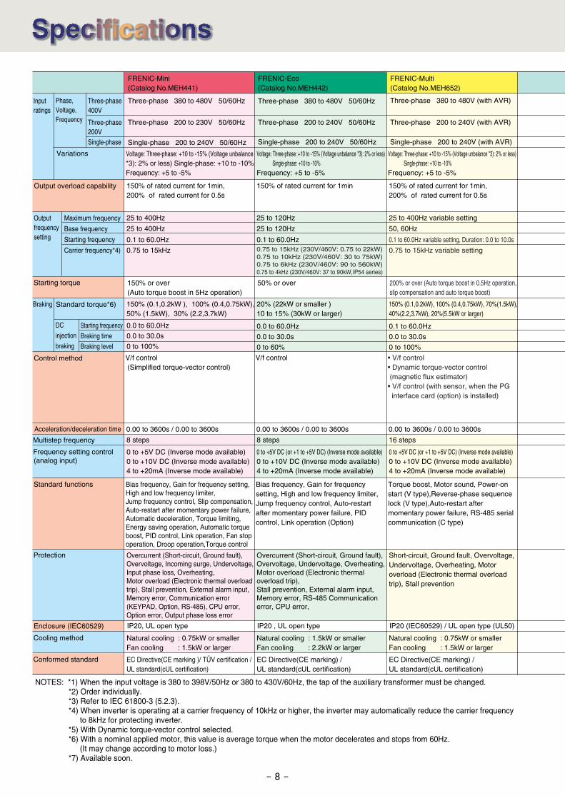
NOTES: *1) When the input voltage is 380 to 398V/50Hz or 380 to 430V/60Hz, the tap of the auxiliary transformer must be changed. *2) Order individually. *3) Refer to IEC 61800-3 (5.2.3). *4) When inverter is operating at a carrier frequency of 10kHz or higher, the inverter may automatically reduce the carrier frequency to 8kHz for protecting inverter. *5) With Dynamic torque-vector control selected. *6) With a nominal applied motor, this value is average torque when the motor decelerates and stops from 60Hz. (It may change according to motor loss.) *7) Available soon.
Input ratings
Phase,Voltage, Frequency
Three-phase400V
Three-phase200VSingle-phase
Variations
Output overload capability
Maximum frequency
Base frequency
Starting frequency
Carrier frequency*4)
Outputfrequencysetting
Starting torque
Braking Standard torque*6)
DC
injection
braking
Control method
Acceleration/deceleration time
Multistep frequency
Frequency setting control (analog input)
Standard functions
Protection
Enclosure (IEC60529)
Conformed standard
FRENIC-Mini (Catalog No.MEH441)
Three-phase 200 to 230V 50/60Hz
Single-phase 200 to 240V 50/60Hz
Three-phase 380 to 480V 50/60Hz
Voltage: Three-phase: +10 to -15% (Voltage unbalance *3): 2% or less) Single-phase: +10 to -10%Frequency: +5 to -5%
150% of rated current for 1min,200% of rated current for 0.5s
25 to 400Hz
25 to 400Hz
0.1 to 60.0Hz
0.75 to 15kHz
150% or over (Auto torque boost in 5Hz operation)
150% (0.1,0.2kW ), 100% (0.4,0.75kW), 50% (1.5kW), 30% (2.2,3.7kW)
0.0 to 60.0Hz
0.0 to 30.0s
0 to 100%
Starting frequency
Braking time
Braking level
V/f control (Simplified torque-vector control)
0.00 to 3600s / 0.00 to 3600s
8 steps
0 to +5V DC (Inverse mode available) 0 to +10V DC (Inverse mode available) 4 to +20mA (Inverse mode available)
Bias frequency, Gain for frequency setting, High and low frequency limiter, Jump frequency control, Slip compensation, Auto-restart after momentary power failure, Automatic deceleration, Torque limiting, Energy saving operation, Automatic torque boost, PID control, Link operation, Fan stop operation, Droop operation,Torque control
Overcurrent (Short-circuit, Ground fault), Overvoltage, Incoming surge, Undervoltage,Input phase loss, Overheating, Motor overload (Electronic thermal overload trip), Stall prevention, External alarm input, Memory error, Communication error (KEYPAD, Option, RS-485), CPU error, Option error, Output phase loss error
IP20, UL open type IP20 , UL open type IP20 (IEC60529) / UL open type (UL50)
EC Directive(CE marking )/ TÜV certification / UL standard(cUL certification)
FRENIC-Eco (Catalog No.MEH442)
Three-phase 200 to 240V 50/60Hz
Three-phase 380 to 480V 50/60Hz
Single-phase 200 to 240V 50/60Hz Single-phase 200 to 240V (with AVR)
Voltage: Three-phase: +10 to -15% (Voltage unbalance *3): 2% or less) Single-phase: +10 to -10%Frequency: +5 to -5%
Voltage: Three-phase: +10 to -15% (Voltage unbalance *3): 2% or less) Single-phase: +10 to -10%Frequency: +5 to -5%
150% of rated current for 1min
25 to 120Hz
25 to 120Hz 50, 60Hz
0.1 to 60.0Hz0.75 to 15kHz (230V/460V: 0.75 to 22kW)0.75 to 10kHz (230V/460V: 30 to 75kW)0.75 to 6kHz (230V/460V: 90 to 560kW)0.75 to 4kHz (230V/460V: 37 to 90kW,IP54 series)
50% or over 200% or over (Auto torque boost in 0.5Hz operation, slip compensation and auto torque boost)
20% (22kW or smaller )10 to 15% (30kW or larger)
0.0 to 60.0Hz
0.0 to 30.0s
0 to 60%
V/f control • V/f control • Dynamic torque-vector control (magnetic flux estimator) • V/f control (with sensor, when the PG interface card (option) is installed)
0.00 to 3600s / 0.00 to 3600s
8 steps
0 to +5V DC (or +1 to +5V DC) (Inverse mode available) 0 to +10V DC (Inverse mode available) 4 to +20mA (Inverse mode available)
Bias frequency, Gain for frequency setting, High and low frequency limiter, Jump frequency control, Auto-restart after momentary power failure, PID control, Link operation (Option)
Overcurrent (Short-circuit, Ground fault), Overvoltage, Undervoltage, Overheating, Motor overload (Electronic thermal overload trip), Stall prevention, External alarm input, Memory error, RS-485 Communication error, CPU error,
EC Directive(CE marking) / UL standard(cUL certification)
FRENIC-Multi (Catalog No.MEH652)
Three-phase 200 to 240V (with AVR)
Three-phase 380 to 480V (with AVR)
150% of rated current for 1min,200% of rated current for 0.5s
25 to 400Hz variable setting
0.1 to 60.0Hz variable setting, Duration: 0.0 to 10.0s
0.75 to 15kHz variable setting
150% (0.1,0.2kW), 100% (0.4,0.75kW), 70%(1.5kW), 40%(2.2,3.7kW), 20%(5.5kW or larger)
0.1 to 60.0Hz
0.0 to 30.0s
0 to 100%
0.00 to 3600s / 0.00 to 3600s
16 steps
0 to +5V DC (or +1 to +5V DC) (Inverse mode available) 0 to +10V DC (Inverse mode available) 4 to +20mA (Inverse mode available)
Torque boost, Motor sound, Power-on start (V type),Reverse-phase sequence lock (V type),Auto-restart after momentary power failure, RS-485 serial communication (C type)
Short-circuit, Ground fault, Overvoltage, Undervoltage, Overheating, Motor overload (Electronic thermal overload trip), Stall prevention
EC Directive(CE marking) / UL standard(cUL certification)
Cooling method Natural cooling : 0.75kW or smallerFan cooling : 1.5kW or larger
Natural cooling : 1.5kW or smallerFan cooling : 2.2kW or larger
Natural cooling : 0.75kW or smallerFan cooling : 1.5kW or larger
- 9 -
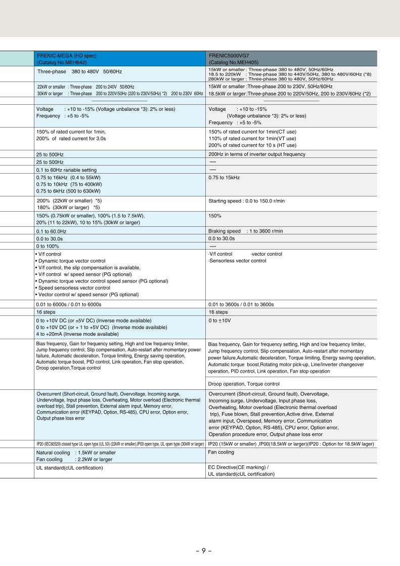
FRENIC-MEGA (HD spec) (Catalog No.MEH642)
Three-phase 380 to 480V 50/60Hz
22kW or smaller : Three-phase 200 to 240V 50/60Hz30kW or larger : Three-phase 200 to 220V/50Hz (220 to 230V/50Hz) *2) 200 to 230V 60Hz
Voltage : +10 to -15% (Voltage unbalance *3): 2% or less)Frequency : +5 to -5%
Voltage : +10 to -15% (Voltage unbalance *3): 2% or less)Frequency : +5 to -5%
150% of rated current for 1min,200% of rated current for 3.0s
150% of rated current for 1min(CT use)110% of rated current for 1min(VT use)200% of rated current for 10 s (HT use)
200Hz in terms of inverter output frequency
Starting speed : 0.0 to 150.0 r/min
-
-
-
25 to 500Hz
25 to 500Hz
0.1 to 60Hz rariable setting
0.75 to 16kHz (0.4 to 55kW)0.75 to 10kHz (75 to 400kW)0.75 to 6kHz (500 to 630kW)
200% (22kW or smaller) *5) 180% (30kW or larger) *5)
150% (0.75kW or smaller), 100% (1.5 to 7.5kW),20% (11 to 22kW), 10 to 15% (30kW or larger)
0.1 to 60.0Hz
0.0 to 30.0s
0 to 100%
• V/f control • Dynamic torque vector control • V/f control, the slip compensation is available. • V/f control w/ speed sensor (PG optional) • Dynamic torque vector control speed sensor (PG optional) • Speed sensorless vector control • Vector control w/ speed sensor (PG optional)
0.01 to 6000s / 0.01 to 6000s
16 steps
0.01 to 3600s / 0.01 to 3600s
16 steps
0 to +-10V
Bias frequency, Gain for frequency setting, High and low frequency limiter,Jump frequency control, Slip compensation, Auto-restart after momentary power failure,Automatic deceleration, Torque limiting, Energy saving operation, Automatic torque boost,Rotating motor pick-up, Line/Inverter changeover operation, PID control, Link operation, Fan stop operation
Droop operation, Torque control
Overcurrent (Short-circuit, Ground fault), Overvoltage, Incoming surge, Undervoltage, Input phase loss,Overheating, Motor overload (Electronic thermal overload trip), Fuse blown, Stall prevention,Active drive, External alarm input, Overspeed, Memory error, Communication error (KEYPAD, Option, RS-485), CPU error, Option error, Operation procedure error, Output phase loss error
IP20 (IEC60529) closed type UL open type (UL 50) (22kW or smaller),IP00 open type, UL open type (30kW or larger)
UL standard(cUL certification)
Bias frequency, Gain for frequency setting, High and low frequency limiter, Jump frequency control, Slip compensation, Auto-restart after momentary power failure, Automatic deceleration, Torque limiting, Energy saving operation, Automatic torque boost, PID control, Link operation, Fan stop operation, Droop operation,Torque control
Overcurrent (Short-circuit, Ground fault), Overvoltage, Incoming surge, Undervoltage, Input phase loss, Overheating, Motor overload (Electronic thermal overload trip), Stall prevention, External alarm input, Memory error, Communication error (KEYPAD, Option, RS-485), CPU error, Option error, Output phase loss error
IP20 (15kW or smaller) ,IP00(18.5kW or larger)(IP20 : Option for 18.5kW lager)
EC Directive(CE marking) / UL standard(cUL certification)
15kW or smaller :Three-phase 200 to 230V, 50Hz/60Hz
15kW or smaller : Three-phase 380 to 480V, 50Hz/60Hz18.5 to 220kW : Three-phase 380 to 440V/50Hz, 380 to 480V/60Hz (*8)280kW or larger : Three-phase 380 to 480V, 50Hz/60Hz
18.5kW or larger :Three-phase 200 to 220V/50Hz, 200 to 230V/60Hz (*2)
FRENIC5000VG7 (Catalog No.MEH405)
0.75 to 15kHz
150%
0 to +10V DC (or ±5V DC) (Inverse mode available) 0 to +10V DC (or + 1 to +5V DC) (Inverse mode available) 4 to +20mA (Inverse mode available)
Natural cooling : 1.5kW or smallerFan cooling : 2.2kW or larger
Fan cooling
Braking speed : 1 to 3600 r/min
0.0 to 30.0s
·V/f control ·vector control ·Sensorless vector control
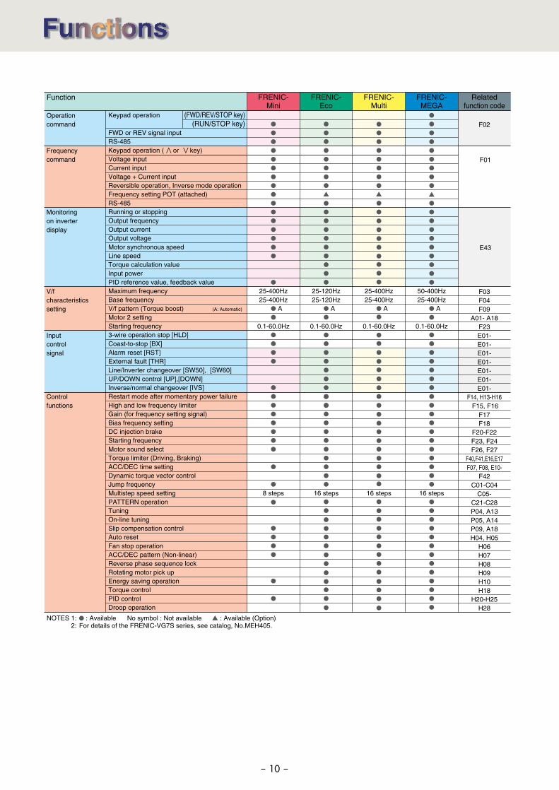
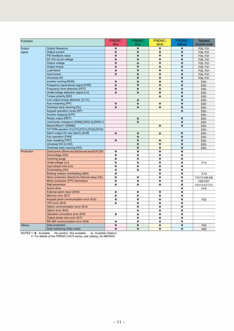
NOTES 1: : Available No symbol : Not available : Available (Option) 2: For details of the FRENIC-VG7S series, see catalog, No.MEH405.
- 10 -
50-400Hz25-400Hz
0.1-60.0Hz
25-400Hz25-400Hz
0.1-60.0Hz
25-120Hz25-120Hz
0.1-60.0Hz
25-400Hz25-400Hz
0.1-60.0Hz
AA AA
16 steps8 steps 16 steps 16 steps
Operationcommand
Frequencycommand
Monitoringon inverterdisplay
V/fcharacteristicssetting
Inputcontrol signal
Controlfunctions
(FWD/REV/STOP key) (RUN/STOP key)
Function FRENIC-MEGA
FRENIC-Mini
FRENIC-Eco
FRENIC-Multi
Relatedfunction code
Keypad operation
FWD or REV signal input RS-485Keypad operation ( or key)Voltage inputCurrent input Voltage + Current inputReversible operation, Inverse mode operationFrequency setting POT (attached) RS-485Running or stopping Output frequency Output current Output voltageMotor synchronous speedLine speed Torque calculation valueInput powerPID reference value, feedback valueMaximum frequencyBase frequencyV/f pattern (Torque boost) (A: Automatic)
Motor 2 setting Starting frequency3-wire operation stop [HLD] Coast-to-stop [BX] Alarm reset [RST] External fault [THR] Line/Inverter changeover [SW50], [SW60] UP/DOWN control [UP],[DOWN] Inverse/normal changeover [IVS]Restart mode after momentary power failureHigh and low frequency limiter Gain (for frequency setting signal)Bias frequency setting DC injection brake Starting frequency Motor sound select Torque limiter (Driving, Braking)ACC/DEC time settingDynamic torque vector controlJump frequency Multistep speed setting PATTERN operation Tuning On-line tuning Slip compensation control Auto reset Fan stop operation ACC/DEC pattern (Non-linear) Reverse phase sequence lock Rotating motor pick up Energy saving operation Torque control PID control Droop operation
F02
F01
E43
F03F04F09
A01- A18F23E01-E01-E01-E01-E01-E01-E01-
F14, H13-H16 F15, F16
F17F18
F20-F22F23, F24F26, F27
F40,F41,E16,E17F07, F08, E10-
F42C01-C04
C05-C21-C28P04, A13P05, A14P09, A18H04, H05
H06H07H08H09H10H18
H20-H25H28
NOTES 1: : Available No symbol : Not available : Available (Option) 2: For details of the FRENIC-VG7S series, see catalog, No.MEH405.
- 11 -
Output frequency Output currentPID feedback value DC link circuit voltageOutput voltage Output torque Load factorInput powerUniversal AO Inverter running [RUN] Frequency equivalence signal [FAR] Frequency level detection [FDT] Undervoltage detection signal [LU]Torque polarity [B/D]Low output torque detected [U-TL] Auto-restarting [IPF] Overload early warning [OL]Keypad operation mode [KP]Inverter stopping [STP]Ready output [RDY] Line/Inverter changeover [SW88],[SW52-2],[SW52-1]Motor2/Motor1 [SWM2] PATTERN operation [TU],[TO],[STG1],[STG2],[STG4] Alarm output (for any alarm) [ALM] Fan operation [FAN] Auto resetting [TRY] Universal DO [U-DO]Overheat early warning [OH] Overcurrent (Short-circuit)(Ground fault)(OC,EF)Overvoltage (OU) Incoming surge Undervoltage (LU) Input phase loss (Lin) Overheating (OH) Braking resistor overheating (dbH) Motor protection (Electronic thermal relay) (OL)Motor protection (PTC thermistor) Stall preventionActive driveExternal alarm input (OH2) Memory error (Er1) Keypad panel communication error (Er2) CPU error (Er3) Option communication error (Er4) Option error (Er5) Operation procedure error (Er6)Output phase loss error (Er7) RS-485 communication error (Er8) Data protection Data initializing (Data reset)
Outputsignal
Protection
FRENIC-MEGA
FRENIC-Mini
FRENIC-Eco
FRENIC-Multi
Relatedfunction code
F30, F31F30, F31F30, F31F30, F31F30, F31F30, F31F30, F31F30, F31F30, F31
E20-E20-E20-E20-E20-E20-E20-E20-E20-E20-E20-E20-E20-E20-E20-E20-E20-E20-E20-
F14
F13F10-F12, A06-A08
H26,H27F40,F41,E16,E17,H12
H19
F02
F00H03
Function
Others
��������
�������������
����������������������������� � ������
���� ���
������������������■���
������������������ ■����
������������������■���
������������������■���
������������������■���
�������������
�����������������
������������ � ���������� ���
����������������■���
����������������■���
����������������■���
����������������� ■����
������������������■���
������������������■���
������������������■���
���������� ����
����������������������������� � ������
���� ���
����������������■���
����������������■���
����������������■���
������������������■����
������������������■���
������������������■���
���������� ����
�����������������
������������ � ���������� ���
�����������������■���
�����������������■���
�����������������■���
���������� ��������
�������������
����������������������������� � ������
���� ���
������������������■���
������������������ ■����
������������������■���
������������������■���
������������������■���
�������������
����������������������������� � ������
���� ���
�����������������■���
�����������������■���
�����������������■���
����������������� ■����
������������������■���
������������������■���
������������������■���
���������� ����
����������������������������� � ������
���� ���
�������������������■����
������������������■���
������������������■���
�������������
�������������
�����������������
������������ � ���������� ���
�������������������■����
������������������■���
������������������■���
������������������■���
������������������■���
������������������■���
�������������������■��
������������������■��
�������������������■����
������������������■��
�����������������■��
������������������■��
�������������������■��
�������������������■��
������������������■��
������������������■��
�������������
����������������������������� � ������
���� ���
�������������������■����
������������������■���
�������������������■���
������������������■���
������������������■���
������������������■���
�������������������■��
������������������■��
�������������������■����
�������������������■��
�����������������■��
������������������■��
������������������■��
���������� ��������
�������������
����������������������������� � ������
���� ���
�������������������■����
������������������■���
������������������■���
������������������■���
������������������■���
������������������■���
�������������������■��
������������������■��
�������������
����������������������������� � ������
���� ���
�������������������■����
������������������■���
�������������������■���
������������������■���
������������������■���
������������������■���
�������������������■��
������������������■��
���������� ���������
�������������
����������������������������� � ������
���� ���
�������������������■����
������������������■���
������������������■���
������������������■���
������������������■���
������������������■���
�������������������■��
������������������■��
�������������������■����
������������������■��
�����������������■��
�����������������■��
������������������■��
������������������■��
�����������������■��
�������������
����������������������������� � ������
���� ���
�������������������■����
������������������■���
�������������������■���
������������������■���
������������������■���
������������������■���
�������������������■��
������������������■��
�������������������■����
�������������������■��
������������������■��
�����������������■��
�����������������■��
������������������■��
������������������■��
��������
�������������
����������������������������� � ������
���� ���
�������������������■����
������������������■���
������������������■���
������������������■���
������������������■���
������������������■���
�������������������■��
������������������■��
�������������������■����
������������������■��
�����������������■��
�����������������■��
������������������■��
������������������■��
�����������������■��
�����������������■��
�������������������■���
������������������■���
������������������■���
�������������������■���
�������������������■���
�������������������■���
�������������������■���
�������������������■���
��������������������■���
�������������������■���
�������������������■���
�������������������■���
�������������
����������������������������� � ������
���� ���
�������������������■����
������������������■���
�������������������■���
������������������■���
������������������■���
������������������■���
�������������������■��
������������������■��
�������������������■����
�������������������■��
�����������������■��
�����������������■��
�����������������■��
������������������■��
�����������������■��
�����������������■��
�������������������■���
■������������ �������������� ������ �� ����������� �� ������������� �� �������� �� �������
■������������ �������������� ������ �� ����������� �� ������������� �� ������������� ������� �� �������� �� �������
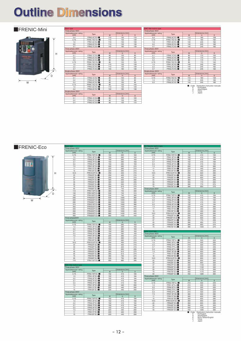
- 12 -
■ FRENIC-Eco
■ FRENIC-Mini
H
D
W
H
D
W
��������
�������������
����������������������������� � ������
���� ���
������������������■���
������������������ ■����
������������������■���
������������������■���
������������������■���
������������������■���
������������������■���
������������������■��
�����������������■��
�������������
����������������������������� � ������
���� ���
����������������■���
����������������■���
�����������������■���
����������������� ■����
������������������■���
������������������■���
������������������■���
������������������■���
������������������■���
�����������������■��
����������������■��
���������� ����
�����������������
������������ � ���������� ���
����������������■���
����������������■���
�����������������■���
������������������■����
������������������■���
������������������■���
���������� ��������
�������������
����������������������������� � ������
���� ���
������������������■���
������������������■����
������������������■���
������������������■���
������������������■���
��������������������■���
��������������������■���
�������������������■��
������������������■��
�������������
����������������������������� � ������
���� ���
�����������������■���
�����������������■���
�����������������■���
�����������������■����
������������������■���
�������������������■���
������������������■���
��������������������■���
��������������������■���
�������������������■��
������������������■��
���������� ����
�����������������
������������ � ���������� ���
�����������������■���
�����������������■���
�����������������■���
������������������■����
������������������■���
������������������■���
���������� ���������������������
�������������
����������������������������� � ������
���� ���
����������������□��■���
����������������□��■����
�����������������□��■���
�����������������□��■���
����������������□��■���
�����������������□��■���
����������������□��■���
����������������□��■��
����������������□��■��
�����������������□��■����
����������������□��■��
��������������������□��■��
��������������������□��■��
��������������������□��■��
��������������������□��■��
��������������������□��■��
��������
�������������
����������������������������� � ������
���� ���
������������������� ����
������������������ ���
����������������������
����������������������
����������������������
����������������������
��������������������
��������������������
������������������ �����
��������������������
��������������������
��������������������
��������������������
��������������������
��������������������
��������������������
��������
�������������
����������������������������� � ������
���� ���
����������������������
����������������������
����������������������
��������������������
��������������������
������������������ �����
��������������������
��������������������
��������������������
��������������������
��������������������
��������������������
��������������������
����������������������
������������������� ���
������������������� ���
�����������������������
�����������������������
������������������� ���
������������������� ���
������������������� ���
�����������������������
�����������������������
�����������������������
������������������� ���
□=��������� ����������� ����������
■������������ �������������� ������ �� ����������� �� ������������� �� ������������� � �� �������� �� �������
■������������ �������������� ������ �� ����������� �� ������������� �� ������������� ������� �� �������� �� �������
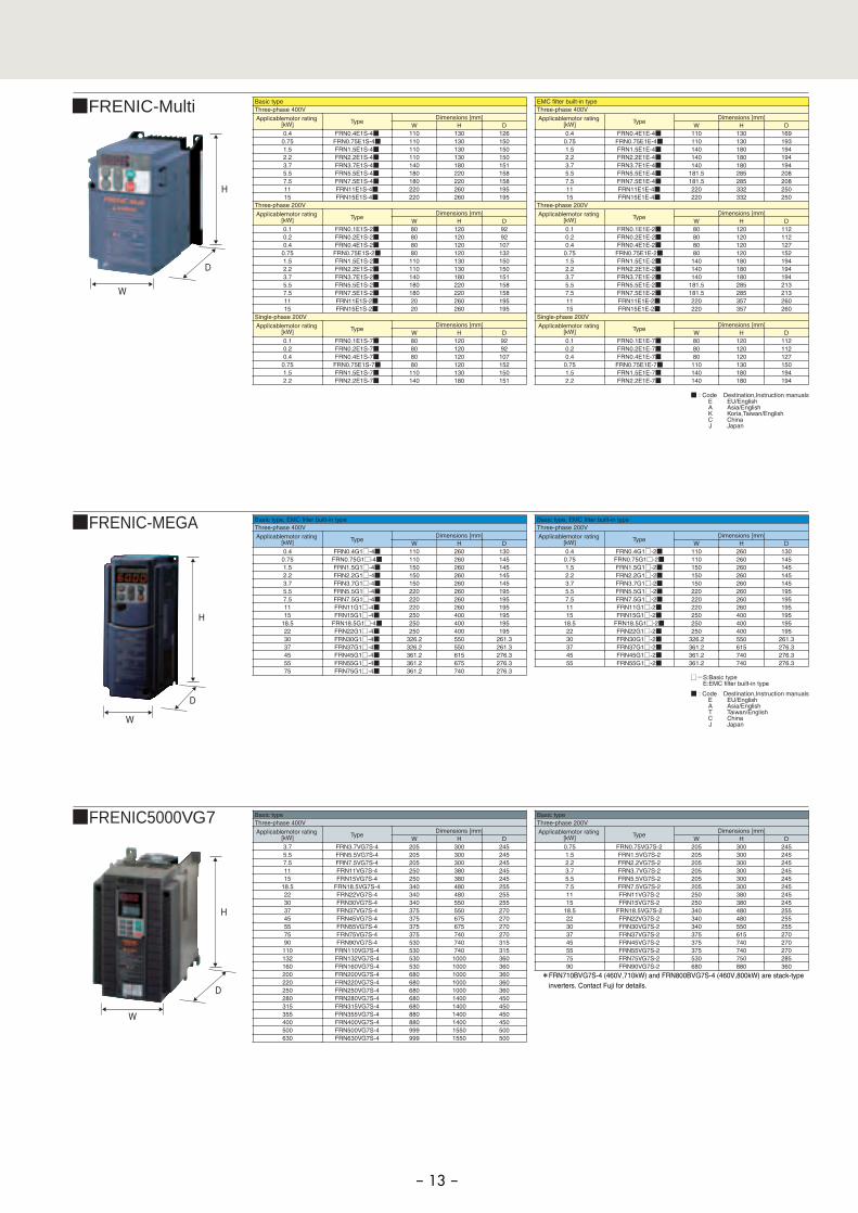
- 13 -
■FRENIC-MEGA
■ FRENIC-Multi
■ FRENIC5000VG7
H
D
W
H
D
W
H
D
W
*FRN710BVG7S-4 (460V,710kW) and FRN800BVG7S-4 (460V,800kW) are stack-type inverters. Contact Fuji for details.
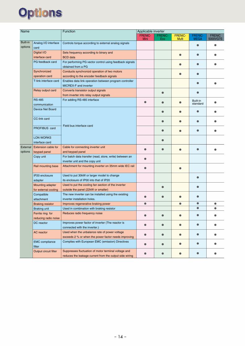
Field bus interface card
- 14 -
Controls torque according to external analog signals
Sets frequency according to binary and
BCD data
For performing PG vector control using feedback signals
obtained from a PG
Conducts synchronizd operation of two motors
according to the encoder feedback signals
Enables data link operation between program controller
MICREX-F and inverter
Converts transistor output signals
from inverter into relay output signals
For adding RS-485 interface
Cable for connecting inverter unit
and keypad panel
For batch data transfer (read, store, write) between an
inverter unit and the copy unit
Attachment for mounting inverter on 35mm wide IEC rail
Used to put 30kW or larger model to change
its enclosure of IP00 into that of IP20
Used to put the cooling fan section of the inverter
outside the panel (22kW or smaller)
The new inverter can be installed using the existing
inverter installation holes.
Improves regenerative braking power
Used in combination with braking resistor
Reduces radio frequency noise
Improves power factor of inverter (The reactor is
connected with the inverter.)
Used when the unbalance rate of power voltage
exceeds 2 % or when the power factor needs improving
Complies with European EMC (emission) Directives
Suppresses fluctuation of motor terminal voltage and
reduces the leakage current from the output side wiring
Built-in
options
External
options
FRENIC-Eco
FRENIC5000VG7S
Name Function Applicable inverter
Analog I/O interface
card
Digital I/O
interface card
PG feedback card
Synchronized
operation card
T-link interface card
Relay output card
RS-485
communication
Device Net Board
CC-link card
PROFIBUS card
LON WORKS
interface card
Extension cable for
keypad panel
Copy unit
Rail mounting base
IP20 enclosure
adapter
Mounting adapter
for external cooling
Compatible
attachment
Braking resistor
Braking unit
Ferrite ring for
reducing radio noise
DC reactor
AC reactor
EMC compliance
filter
Output circuit filter
FRENIC-Mini
FRENIC-Multi
FRENIC-MEGA
Built-in standard
- 15 -
WarrantyTo all our customers who purchase
Fuji Electric FA Components & Systems' products:
Please take the following items into consideration when placing your order.
When requesting an estimate and placing your orders for the products included in these materials, please be aware that any items such as specifications which are not specifically mentioned in the contract, catalog, specifications or other materials will be as mentioned below.In addition, the products included in these materials are limited in the use they are put to and the place where they can be used, etc., and may require periodic inspection. Please confirm these points with your sales representative or directly with this company.Furthermore, regarding purchased products and delivered products, we request that you take adequate consideration of the necessity of rapid receiving inspections and of product management and maintenance even before receiving your products.
(1) The product warranty period is ''1 year from the date of purchase'' or 24 months from the manufacturing date imprinted on the name place, whichever date is earlier.
(2) However, in cases where the use environment, conditions of use, use frequency and times used, etc., have an effect on product life, this warranty period may not apply.
(3) Furthermore, the warranty period for parts restored by Fuji Electric's Service Department is ''6 months from the date
As a rule, the customer is requested to carry out a preliminary trouble diagnosis. However, at the customer's request, this company or its service network can perform the trouble diagnosis on a chargeable basis. In this case, the customer is asked to assume the burden for charges levied in accordance with this company's fee schedule.
Regardless of whether a breakdown occurs during or after the free of charge warranty period, this company shall not be liable for any loss of opportunity, loss of profits, or damages arising from special circumstances, secondary damages, accident compensation to another company, or damages to products other than this company's products, whether foreseen or not by this company, which this company is not be responsible for causing.
1. Free of Charge Warranty Period and Warranty Range
2. Exclusion of Liability for Loss of Opportunity, etc.
Concerning models (products) which have gone out of production, this company will perform repairs for a period of 7 years after production stop, counting from the month and year when the production stop occurs. In addition, we will continue to supply the spare parts required for repairs for a period of 7 years, counting from the month and year when the production stop occurs. However, if it is estimated that the life cycle of certain electronic and other parts is short and it will be difficult to procure or produce those parts, there may be cases where it is difficult to provide repairs or supply spare parts even within this 7-year period. For details, please confirm at our company's business office or our service office.
3. Repair Period after Production Stop, Spare Parts Supply Period (Holding Period)
In the case of standard products which do not include settings or adjustments in an application program, the products shall be transported to and transferred to the customer and this company shall not be responsible for local adjustments or trial operation.
4. Transfer Rights
The cost of purchased and delivered products does not include the cost of dispatching engineers or service costs. Depending on the request, these can be discussed separately.
5. Service Contents
Above contents shall be assumed to apply to transactions and use of the country where you purchased the products.Consult the local supplier or Fuji for the detail separately.
6. Applicable Scope of Service
1-1 Free of charge warranty period
(1) In the event that breakdown occurs during the product's warranty period which is the responsibility of Fuji Electric, Fuji Electric will replace or repair the part of the product that has broken down free of charge at the place where the product was purchased or where it was delivered. However, if the following cases are applicable, the terms of this warranty may not apply.
1) The breakdown was caused by inappropriate conditions, environment, handling or use methods, etc. which are not specified in the catalog, operation manual, specifications or other relevant documents.
2) The breakdown was caused by the product other than the purchased or delivered Fuji's product.3) The breakdown was caused by the product other than Fuji's product, such as the customer's equipment or
software design, etc.4) Concerning the Fuji's programmable products, the breakdown was caused by a program other than a program
supplied by this company, or the results from using such a program.5) The breakdown was caused by modifications or repairs affected by a party other than Fuji Electric.6) The breakdown was caused by improper maintenance or replacement using consumables, etc. specified in the
operation manual or catalog, etc.7) The breakdown was caused by a chemical or technical problem that was not foreseen when making practical
application of the product at the time it was purchased or delivered.8) The product was not used in the manner the product was originally intended to be used.9) The breakdown was caused by a reason which is not this company's responsibility, such as lightning or other
disaster.(2) Furthermore, the warranty specified herein shall be limited to the purchased or delivered product alone.(3) The upper limit for the warranty range shall be as specified in item (1) above and any damages (damage to or loss
of machinery or equipment, or lost profits from the same, etc.) consequent to or resulting from breakdown of the purchased or delivered product shall be excluded from coverage by this warranty.
1-2 Warranty range
1-3. Trouble diagnosis
NOTES
When running general-purpose motors
• Driving a 400V general-purpose motorWhen driving a 400V general-purpose motor with an inverter using extremely long cables, damage to the insulation of the motor may occur. Use an output circuit filter (OFL) if necessary after checking with the motor manufacturer. Fuji's motors do not require the use of output circuit filters because of their reinforced insulation.
• Torque characteristics and temperature riseWhen the inverter is used to run a general-purpose motor, the temperature of the motor becomes higher than when it is operated using a commercial power supply. In the low-speed range, the cooling effect will be weakened, so decrease the output torque of the motor. If constant torque is required in the low-speed range, use a Fuji inverter motor or a motor equipped with an externally powered ventilating fan.
• VibrationWhen the motor is mounted to a machine, resonance may be caused by the natural frequencies, including that of the machine. Operation of a 2-pole motor at 60Hz or more may cause abnormal vibration.* Study use of tier coupling or dampening rubber.* It is also recommended to use the inverter jump
frequency control to avoid resonance points.
• NoiseWhen an inverter is used with a general-purpose motor, the motor noise level is higher than that with a commercial power supply. To reduce noise, raise carrier frequency of the inverter. High-speed operation at 60Hz or more can also result in more noise.
When running special motors
• High-speed motorsWhen driving a high-speed motor while setting the frequency higher than 120Hz, test the combination with another motor to confirm the safety of high-speed motors.
• Explosion-proof motorsWhen driving an explosion-proof motor with an inverter, use a combination of a motor and an inverter that has been approved in advance.
• Submersible motors and pumpsThese motors have a larger rated current than general-purpose motors. Select an inverter whose rated output current is greater than that of the motor.These motors differ from general-purpose motors in thermal characteristics. Set a low value in the thermal time constant of the motor when setting the electronic thermal facility.
• Brake motorsFor motors equipped with parallel-connected brakes, their braking power must be supplied from the primary circuit (commercial power supply). If the brake power is connected to the inverter power output circuit (secondary circuit) by mistake, problems may occur.Do not use inverters for driving motors equipped with series-connected brakes.
• Geared motorsIf the power transmission mechanism uses an oil-
lubricated gearbox or speed changer/reducer, then continuous motor operation at low speed may cause poor lubrication. Avoid such operation.
• Synchronous motorsIt is necessary to use software suitable for this motor type. Contact Fuji for details.
• Single-phase motorsSingle-phase motors are not suitable for inverter-driven variable speed operation. Use three-phase motors.* Even if a single-phase power supply is available, use a three-phase motor as the inverter provides three-phase output.
Environmental conditions
• Installation locationUse the inverter in a location with an ambient temperature range of -10 to 50˚C.The inverter and braking resistor surfaces become hot under certain operating conditions. Install the inverter on nonflammable material such as metal.Ensure that the installation location meets the environmental conditions specified in "Environment" in inverter specifications.
Combination with peripheral devices
• Installing a molded case circuit breaker (MCCB)Install a recommended molded case circuit breaker (MCCB) or an earth leakage circuit breaker (ELCB) in the primary circuit of each inverter to protect the wiring. Ensure that the circuit breaker capacity is equivalent to or lower than the recommended capacity.
• Installing a magnetic contactor (MC) in the output (secondary) circuitIf a magnetic contactor (MC) is mounted in the inverter's secondary circuit for switching the motor to commercial power or for any other purpose, ensure that both the inverter and the motor are fully stopped before you turn the MC on or off. Remove the surge killer integrated with the MC.
• Installing a magnetic contactor (MC) in the input (primary) circuitDo not turn the magnetic contactor (MC) in the primary circuit on or off more than once an hour as an inverter fault may result. If frequent starts or stops are required during motor operation, use FWD/REV signals.
• Protecting the motorThe electronic thermal facility of the inverter can protect the motor. The operation level and the motor type (general-purpose motor, inverter motor) should be set. For high-speed motors or water-cooled motors, set a small value for the thermal time constant to protect the motor.If you connect the motor thermal relay to the motor with a long cable, a high-frequency current may flow into the wiring stray capacitance. This may cause the relay to trip at a current lower than the set value for the thermal relay. If this happens, lower the carrier frequency or use the output circuit filter (OFL).
• Discontinuance of power-factor correcting capacitorDo not mount power factor correcting capacitors in the inverter (primary) circuit. (Use the DC REACTOR to improve the inverter power factor.) Do
not use power factor correcting capacitors in the inverter output circuit (secondary). An overcurrent trip will occur, disabling motor operation.
• Discontinuance of surge killerDo not mount surge killers in the inverter output (secondary) circuit.
• Reducing noiseUse of a filter and shielded wires are typical measures against noise to ensure that EMC Directives are met.
• Measures against surge currentsIf an overvoltage trip occurs while the inverter is stopped or operated under a light load, it is assumed that the surge current is generated by open/close of the phase-advancing capacitor in the power system.We recommend connecting a DC REACTOR to the inverter.
• Megger testWhen checking the insulation resistance of the inverter, use a 500V megger and follow the instructions contained in the Instruction Manual.
Wiring
• Wiring distance of control circuitWhen performing remote operation, use the twisted shield wire and limit the distance between the inverter and the control box to 20m.
• Wiring length between inverter and motorIf long wiring is used between the inverter and the motor, the inverter will overheat or trip as a result of overcurrent (high-frequency current flowing into the stray capacitance) in the wires connected to the phases. Ensure that the wiring is shorter than 50m. If this length must be exceeded, lower the carrier frequency or mount an output circuit filter (OFL).
• Wiring sizeSelect cables with a sufficient capacity by referring to the current value or recommended wire size.
• Wiring typeDo not use multicore cables that are normally used for connecting several inverters and motors.
• GroundingSecurely ground the inverter using the grounding terminal.
Selecting inverter capacity
• Driving general-purpose motorSelect an inverter according to the applicable motor ratings listed in the standard specifications table for the inverter. When high starting torque is required or quick acceleration or deceleration is required, select an inverter with a capacity one size greater than the standard.
• Driving special motorsSelect an inverter that meets the following condition:Inverter rated current > Motor rated current.
Transportation and storage
When transporting or storing inverters, follow the procedures and select locations that meet the environmental conditions that agree with the inverter specifications.
Mitsui Sumitomo Bank Ningyo-cho Bldg.,5-7,Nihonbashi Odemma-cho,Chuo-ku,Tokyo 103-0011,JapanPhone: +81-3-5847-8011 Fax: +81-3-5847-8172
Information in this catalog is subject to change without notice. Printed in Japan 2008-4 (D08a/A00) CM 30 FIS
Printed on recycled paper

![TS1000 Smart Connection Manual [2] - Fuji Electric · For details on devices including PLCs, inverters, and temperature controllers, refer to the manual for each device. Manual Name](https://img.pdfslide.us/doc/110x75/5f1ac0888dcf9d01b345138d/ts1000-smart-connection-manual-2-fuji-electric-for-details-on-devices-including.jpg)


![index [exhibitors.productronica.com] · 2019-08-08 · HOLDER FUJI NXT N610071334AA FUJI NXT H04 SMT N610059928AA WPH2030 FUJI Filter XH00400 N610071334AA DCPH0630 FUJI CP7 FILTER](https://img.pdfslide.us/doc/110x75/5e9f95a3be23337fb22f1412/index-2019-08-08-holder-fuji-nxt-n610071334aa-fuji-nxt-h04-smt-n610059928aa.jpg)