Embed Size (px)
Citation preview
FUGRO LOADTEST Osterberg Cell Technology in London, UK
LONDON The history of London, a truly global city, goes back over two millennia when it was first founded by the Romans who named it Londinium. Nowadays, the modern London is a truly cosmopolitan city consisting of a diverse range of peoples and cultures, over 300 different languages are said to be spoken within its boundaries. With a population of over 8m residents and many more coming in and through the city daily, the infrastructure and facilities are in constant need of upgrading and updating. Several major projects have called upon the services of Fugro Loadtest and O-cell technology to assist with load testing and design optimisation in typically tight and congested construction sites across the London area. HEATHROW AIRPORT T5 The first bi-directional load test project undertaken was at the initial construction phase at the site of T5 terminal at Heathrow Airport. To assist the designers in understanding of the nature of the soils and their characteristic behaviour under loading, O-cell testing was included as part of a comprehensive testing program. New Providence Wharf The East End of London was, for many years, a site of pollution and dereliction, being the area used for coal gas production and cheap social housing to fulfil the housing needs of the workers at London’s once thriving docklands. New Providence Wharf was the site for the second Osterberg Cell test in the United Kingdom. This project formed part of the redevelopment of the Isle of Dogs area of London with the construction of luxury apartments providing easy access to the City Centre and the commercial heart of the banking district of Canary Wharf. As part of a value engineering program undertaken by Stent Foundations Ltd. (now BBGE), a 670 mm diameter O-cell was installed 0.65 metres above the 1100 mm pile, 36.2 m long test pile. The pile was loaded to a combined skin friction and end bearing of more than 18.3 MN THAMESLINK PROGRAM Farringdon Station Redevelopment Farringdon sits at the heart of a major investment in London’s railway network. From this station passengers will be able to traverse the city on the brand new Crossrail and Thameslink trains, and access some of our country's major international gateways. The new integrated ticket hall will link the city's north/south Thameslink trains with Crossrail's east/west services and London Underground. This will bring passengers from areas such as Barnet and Croydon closer to Heathrow, the City and Canary Wharf - vastly improving travel across London and beyond. Positioning of the piles proved a demanding challenge for the piling, construction and design teams from Expanded Piling Co. Ltd., CoLOR (Costain Laing O’Rourke JV), Network Rail and Atkins Ltd. The piles needed to avoid the Thameslink tracks, London Underground existing tunnels, the proposed route for the Crossrail Project and the main sewers below. Copyright©FugroLoadtest2015
City of London
Canary Wharf, London
The Completed T5 Building at
Heathrow
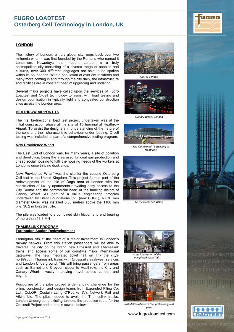
New Providence Wharf
Artist Impression of the completed ticket hall.
Installation of one of the preliminary test
piles
www.fugro-loadtest.com
FUGRO LOADTEST Osterberg Cell Technology in London, UK
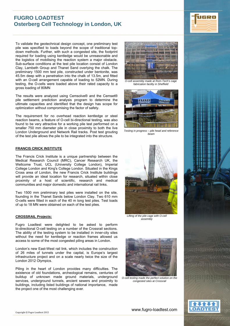
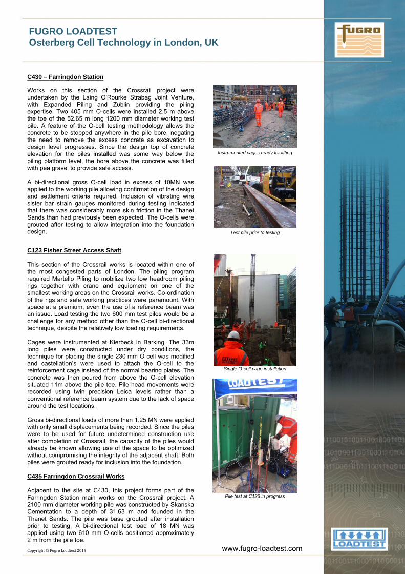
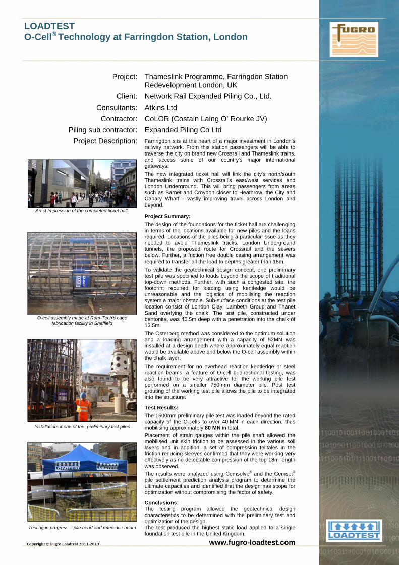
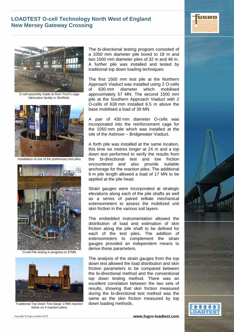
To validate the geotechnical design concept, one preliminary test pile was specified to loads beyond the scope of traditional top-down methods. Further, with such a congested site, the footprint required for loading using kentledge would be unreasonable and the logistics of mobilising the reaction system a major obstacle. Sub-surface conditions at the test pile location consist of London Clay, Lambeth Group and Thanet Sand overlying the chalk. The preliminary 1500 mm test pile, constructed under bentonite, was 45.5m deep with a penetration into the chalk of 13.5m, and fitted with an O-cell arrangement capable of loading to 52MN. During testing, the O-cells were loaded above their rated capacity to a gross loading of 80MN The results were analyzed using Cemsolve® and the Cemset® pile settlement prediction analysis program to determine the ultimate capacities and identified that the design has scope for optimization without compromising the factor of safety. The requirement for no overhead reaction kentledge or steel reaction beams, a feature of O-cell bi-directional testing, was also found to be very attractive for a working pile test performed on a smaller 750 mm diameter pile in close proximity to both the live London Underground and Network Rail tracks. Post test grouting of the test pile allows the pile to be integrated into the structure. FRANCIS CRICK INSTITUTE The Francis Crick Institute is a unique partnership between the Medical Research Council (MRC), Cancer Research UK, the Wellcome Trust, UCL (University College London), Imperial College London and King's College London. Situated in the Kings Cross area of London, the new Francis Crick Institute buildings will provide an ideal location for research, situated within close proximity of a host of scientific, research and medical communities and major domestic and international rail links. Two 1500 mm preliminary test piles were installed on the site, founding in the Thanet Sands below London Clay. Two 610 mm O-cells were fitted in each of the 40 m long test piles. Test loads of up to 18 MN were obtained on each of the test plies. CROSSRAIL Projects: Fugro Loadtest were delighted to be asked to perform bi-directional O-cell testing on a number of the Crossrail sections. The ability of the testing system to be installed in inner-city sites without the need for kentledge or reaction frames allowed us access to some of the most congested piling areas in London. London’s new East-West rail link, which includes the construction of 26 miles of tunnels under the capital, is Europe’s largest infrastructure project and on a scale nearly twice the size of the London 2012 Olympics. Piling in the heart of London provides many difficulties. The existence of old foundations, archeological remains, centuries of buildup of unknown made ground materials, underground services, underground tunnels, ancient sewers and proximity to buildings, including listed buildings of national importance, made the project one of the most challenging ever.
Copyright©FugroLoadtest2015
O-cell assembly made at Rom-Tech’s cage
fabrication facility in Sheffield
Testing in progress – pile head and reference
beam
Lifting of the pile cage with O-cell
assembly
O-cell testing made the perfect solution on the
congested sites at Crossrail
www.fugro-loadtest.com
FUGRO LOADTEST Osterberg Cell Technology in London, UK
C430 – Farringdon Station Works on this section of the Crossrail project were undertaken by the Laing O'Rourke Strabag Joint Venture, with Expanded Piling and Zϋblin providing the piling expertise. Two 405 mm O-cells were installed 2.5 m above the toe of the 52.65 m long 1200 mm diameter working test pile. A feature of the O-cell testing methodology allows the concrete to be stopped anywhere in the pile bore, negating the need to remove the excess concrete as excavation to design level progresses. Since the design top of concrete elevation for the piles installed was some way below the piling platform level, the bore above the concrete was filled with pea gravel to provide safe access. A bi-directional gross O-cell load in excess of 10MN was applied to the working pile allowing confirmation of the design and settlement criteria required. Inclusion of vibrating wire sister bar strain gauges monitored during testing indicated that there was considerably more skin friction in the Thanet Sands than had previously been expected. The O-cells were grouted after testing to allow integration into the foundation design. C123 Fisher Street Access Shaft This section of the Crossrail works is located within one of the most congested parts of London. The piling program required Martello Piling to mobilize two low headroom piling rigs together with crane and equipment on one of the smallest working areas on the Crossrail works. Co-ordination of the rigs and safe working practices were paramount. With space at a premium, even the use of a reference beam was an issue. Load testing the two 600 mm test piles would be a challenge for any method other than the O-cell bi-directional technique, despite the relatively low loading requirements. Cages were instrumented at Kierbeck in Barking. The 33m long piles were constructed under dry conditions, the technique for placing the single 230 mm O-cell was modified and castellation’s were used to attach the O-cell to the reinforcement cage instead of the normal bearing plates. The concrete was then poured from above the O-cell elevation situated 11m above the pile toe. Pile head movements were recorded using twin precision Leica levels rather than a conventional reference beam system due to the lack of space around the test locations. Gross bi-directional loads of more than 1.25 MN were applied with only small displacements being recorded. Since the piles were to be used for future undetermined construction use after completion of Crossrail, the capacity of the piles would already be known allowing use of the space to be optimized without compromising the integrity of the adjacent shaft. Both piles were grouted ready for inclusion into the foundation. C435 Farringdon Crossrail Works Adjacent to the site at C430, this project forms part of the Farringdon Station main works on the Crossrail project. A 2100 mm diameter working pile was constructed by Skanska Cementation to a depth of 31.63 m and founded in the Thanet Sands. The pile was base grouted after installation prior to testing. A bi-directional test load of 18 MN was applied using two 610 mm O-cells positioned approximately 2 m from the pile toe.
Copyright©FugroLoadtest2015
Instrumented cages ready for lifting
Test pile prior to testing
Single O-cell cage installation
Pile test at C123 in progress
www.fugro-loadtest.com
LOADTEST O-Cell® Technology at Farringdon Station, London
Project:
Client: Consultants:
Contractor: Piling sub contractor:
Project Description:
Artist Impression of the completed ticket hall.
O-cell assembly made at Rom-Tech’s cage
fabrication facility in Sheffield
Installation of one of the preliminary test piles
Testing in progress – pile head and reference beam
Copyright © Fugro Loadtest 2011-2013
Thameslink Programme, Farringdon Station Redevelopment London, UK Network Rail Expanded Piling Co., Ltd. Atkins Ltd CoLOR (Costain Laing O’ Rourke JV) Expanded Piling Co Ltd Farringdon sits at the heart of a major investment in London’s railway network. From this station passengers will be able to traverse the city on brand new Crossrail and Thameslink trains, and access some of our country's major international gateways. The new integrated ticket hall will link the city's north/south Thameslink trains with Crossrail's east/west services and London Underground. This will bring passengers from areas such as Barnet and Croydon closer to Heathrow, the City and Canary Wharf - vastly improving travel across London and beyond.
Project Summary:
The design of the foundations for the ticket hall are challenging in terms of the locations available for new piles and the loads required. Locations of the piles being a particular issue as they needed to avoid Thameslink tracks, London Underground tunnels, the proposed route for Crossrail and the sewers below. Further, a friction free double casing arrangement was required to transfer all the load to depths greater than 18m. To validate the geotechnical design concept, one preliminary test pile was specified to loads beyond the scope of traditional top-down methods. Further, with such a congested site, the footprint required for loading using kentledge would be unreasonable and the logistics of mobilising the reaction system a major obstacle. Sub-surface conditions at the test pile location consist of London Clay, Lambeth Group and Thanet Sand overlying the chalk. The test pile, constructed under bentonite, was 45.5m deep with a penetration into the chalk of 13.5m. The Osterberg method was considered to the optimum solution and a loading arrangement with a capacity of 52MN was installed at a design depth where approximately equal reaction would be available above and below the O-cell assembly within the chalk layer. The requirement for no overhead reaction kentledge or steel reaction beams, a feature of O-cell bi-directional testing, was also found to be very attractive for the working pile test performed on a smaller 750 mm diameter pile. Post test grouting of the working test pile allows the pile to be integrated into the structure.
Test Results:
The 1500mm preliminary pile test was loaded beyond the rated capacity of the O-cells to over 40 MN in each direction, thus mobilising approximately 80 MN in total. Placement of strain gauges within the pile shaft allowed the mobilised unit skin friction to be assessed in the various soil layers and in addition, a set of compression telltales in the friction reducing sleeves confirmed that they were working very effectively as no detectable compression of the top 18m length was observed. The results were analyzed using Cemsolve® and the Cemset® pile settlement prediction analysis program to determine the ultimate capacities and identified that the design has scope for optimization without compromising the factor of safety.
Conclusions: The testing program allowed the geotechnical design characteristics to be determined with the preliminary test and optimization of the design. The test produced the highest static load applied to a single foundation test pile in the United Kingdom.
www.fugro-loadtest.com

LOADTEST O-cell Technology North West of England New Mersey Gateway Crossing
Project: Location:
Client: Consultant:
The Mersey Gateway Bridge Project
Runcorn and Widnes, UK Bachy Soletance Ltd Flint & Neill
Project Description:
Artist Rendering of Mersey Gateway Bridge with the
Silver Jubilee bridge in the foregroundSource: www.merseygateway.co.uk
The Mersey Gateway Bridge Project is a major scheme to create a new six-lane toll bridge over the River Mersey between the towns of Runcorn and Widnes. This will alleviate the congestion on the ailing and ageing Silver Jubilee Bridge where every weekday 80,000 vehicles cross – ten times its traffic design. The new bridge will lead to the infrastructure investments required to deliver regeneration of the North West and provide a major strategic transportation route, linking the Liverpool city-region, north Cheshire and the North West to the rest of the UK.
A wide range of options have been considered for the design of the bridge and that of the second Severn Crossing, a cable-stayed structure, served as an ideal design as this will bring maximum benefits for users and make less impact on the estuary and the local environment.
Artist Rendering of Mersey Gateway Bridge
Source: www.merseygateway.co.uk
In contrast, to the Severn Crossing, the Mersey Gateway Bridge Project design has three towers, the central being the shorter (80m high) than the north tower (110 m high) and the south tower (125 m high). It will be 2,130 m long (including the approach viaducts on each side) with a river span of 1,000 metres.
To verify the suitability of the foundation design at the viaduct approaches, the designers sought involvement of Fugro Loadtest to carry out a preliminary pile load test. Four preliminary test piles were load tested.
Source: www.merseygateway.co.uk Copyright©FugroLoadtest2015 www.fugro-loadtest.com
LOADTEST O-cell Technology North West of England New Mersey Gateway Crossing
O-cell assembly made at Rom-Tech’s cage
fabrication facility in Sheffield.
Installation of one of the preliminary test piles
O-cell Pile testing in progress to 57MN
Traditional Top Down Test (large 17MN reaction
frame on 4 reaction piles)
Copyright©FugroLoadtest2015
The bi-directional testing program consisted of a 1050 mm diameter pile bored to 18 m and two 1500 mm diameter piles of 32 m and 48 m. A further pile was installed and tested by traditional top down loading techniques. The first 1500 mm test pile at the Northern Approach Viaduct was installed using 2 O-cells of 630 mm diameter which mobilised approximately 57 MN. The second 1500 mm pile at the Southern Approach Viaduct with 2 O-cells of 630 mm installed 6.5 m above the base mobilised a load of 39 MN. A pair of 430 mm diameter O-cells was incorporated into the reinforcement cage for the 1050 mm pile which was installed at the site of the Astmoor – Bridgewater Viaduct. A forth pile was installed at the same location, this time six metres longer at 24 m and a top down test performed to verify the results from the bi-directional test and low friction encountered and also provide suitable anchorage for the reaction piles. The additional 6 m pile length allowed a load of 17 MN to be applied at the pile head. Strain gauges were incorporated at strategic elevations along each of the pile shafts as well as a series of paired telltale mechanical extensometers to assess the mobilized unit skin friction in the various soil layers. The embedded instrumentation allowed the distribution of load and estimation of skin friction along the pile shaft to be defined for each of the test piles. The addition of extensometers to complement the strain gauges provided an independent means to derive these parameters. The analysis of the strain gauges from the top down test allowed the load distribution and skin friction parameters to be compared between the bi-directional method and the conventional top down testing method. There was an excellent correlation between the two sets of results, showing that skin friction measured during the bi-directional test method was the same as the skin friction measured by top down loading methods.
www.fugro-loadtest.com
LOW HEADROOM STATIC LOAD TESTING O-Cell® Technology at 22 BISHOPSGATE, LONDON, UK
Project:
Client:
Consultants:
Contractor:
According to City A.M. The new building "fills an obvious gap" in the City, its developers said (Source: Axa Real Estate) www.cityam.com
Martello’s low headroom rig in action
Installation of the O-cell and reinforcing cage for
the test pile
Copyright©Fugro2016
22 Bishopsgate, London, UK
Martello Piling
WSP
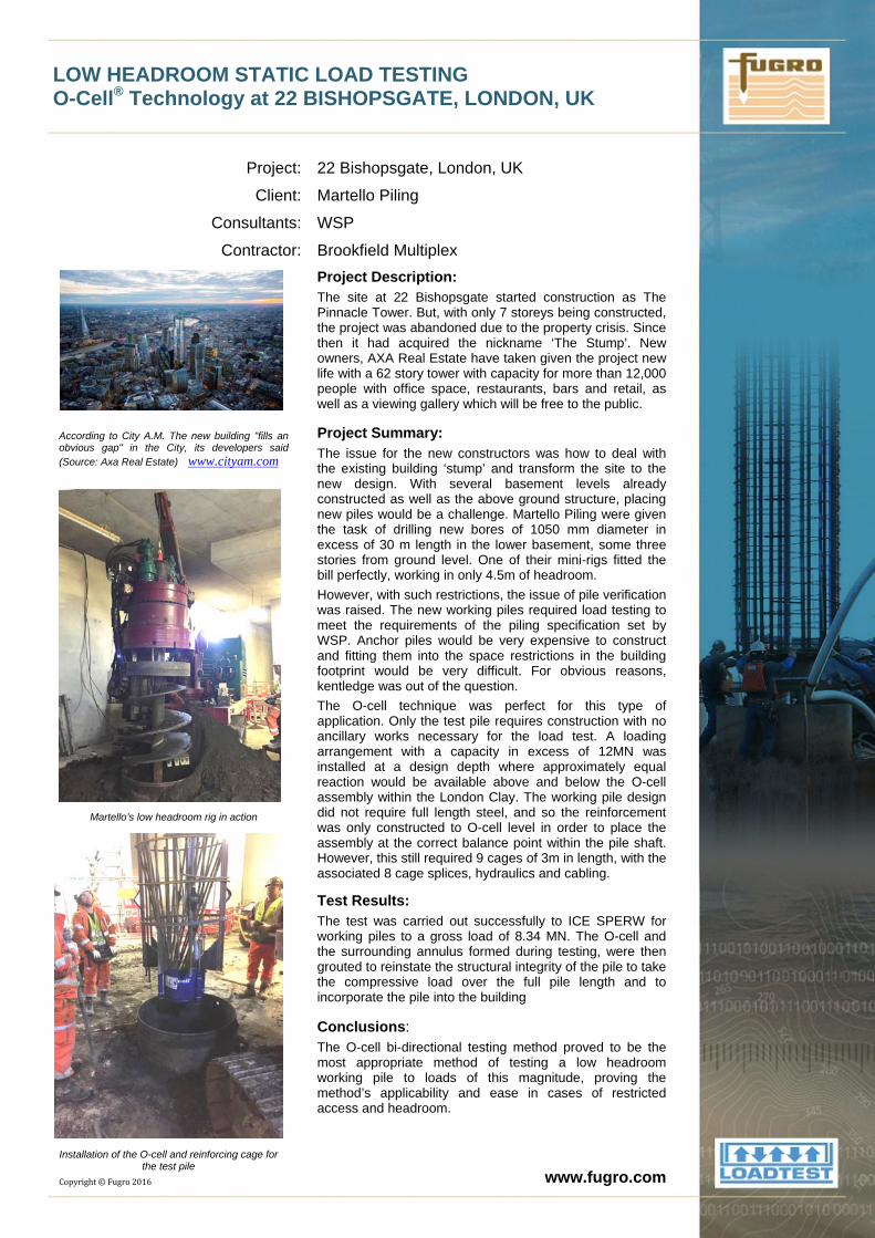
Brookfield Multiplex Project Description: The site at 22 Bishopsgate started construction as The Pinnacle Tower. But, with only 7 storeys being constructed, the project was abandoned due to the property crisis. Since then it had acquired the nickname ‘The Stump’. New owners, AXA Real Estate have taken given the project new life with a 62 story tower with capacity for more than 12,000 people with office space, restaurants, bars and retail, as well as a viewing gallery which will be free to the public.
Project Summary: The issue for the new constructors was how to deal with the existing building ‘stump’ and transform the site to the new design. With several basement levels already constructed as well as the above ground structure, placing new piles would be a challenge. Martello Piling were given the task of drilling new bores of 1050 mm diameter in excess of 30 m length in the lower basement, some three stories from ground level. One of their mini-rigs fitted the bill perfectly, working in only 4.5m of headroom. However, with such restrictions, the issue of pile verification was raised. The new working piles required load testing to meet the requirements of the piling specification set by WSP. Anchor piles would be very expensive to construct and fitting them into the space restrictions in the building footprint would be very difficult. For obvious reasons, kentledge was out of the question. The O-cell technique was perfect for this type of application. Only the test pile requires construction with no ancillary works necessary for the load test. A loading arrangement with a capacity in excess of 12MN was installed at a design depth where approximately equal reaction would be available above and below the O-cell assembly within the London Clay. The working pile design did not require full length steel, and so the reinforcement was only constructed to O-cell level in order to place the assembly at the correct balance point within the pile shaft. However, this still required 9 cages of 3m in length, with the associated 8 cage splices, hydraulics and cabling.
Test Results: The test was carried out successfully to ICE SPERW for working piles to a gross load of 8.34 MN. The O-cell and the surrounding annulus formed during testing, were then grouted to reinstate the structural integrity of the pile to take the compressive load over the full pile length and to incorporate the pile into the building Conclusions: The O-cell bi-directional testing method proved to be the most appropriate method of testing a low headroom working pile to loads of this magnitude, proving the method’s applicability and ease in cases of restricted access and headroom.
www.fugro.com
LOADTEST First UK use of O-cell Technology in a CFA pile Brighton Marina
Project: Location:
Developer : Main contractor:
Piling Contractor:
Brighton Marina Development
Brighton, East Sussex, UK Brunswick Developments J Reddington Miller Piling Limited
Project Description:
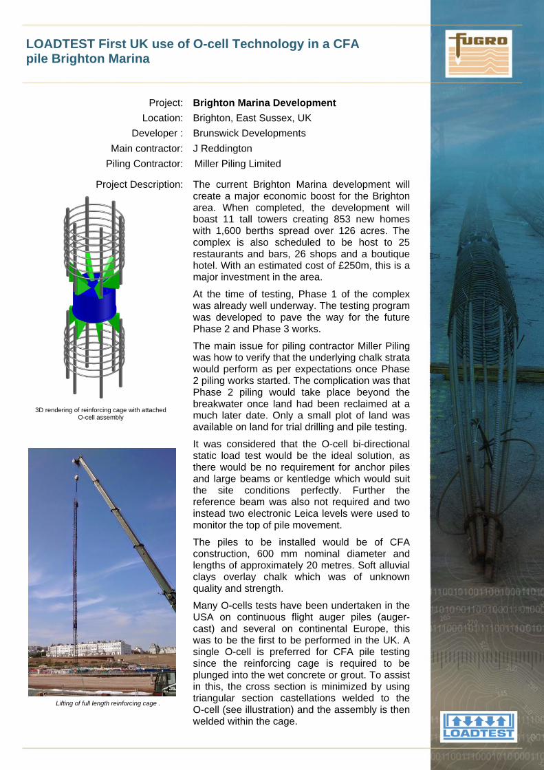
3D rendering of reinforcing cage with attached
O-cell assembly
The current Brighton Marina development will create a major economic boost for the Brighton area. When completed, the development will boast 11 tall towers creating 853 new homes with 1,600 berths spread over 126 acres. The complex is also scheduled to be host to 25 restaurants and bars, 26 shops and a boutique hotel. With an estimated cost of £250m, this is a major investment in the area.
At the time of testing, Phase 1 of the complex was already well underway. The testing program was developed to pave the way for the future Phase 2 and Phase 3 works.
The main issue for piling contractor Miller Piling was how to verify that the underlying chalk strata would perform as per expectations once Phase 2 piling works started. The complication was that Phase 2 piling would take place beyond the breakwater once land had been reclaimed at a much later date. Only a small plot of land was available on land for trial drilling and pile testing.
Artist
Lifting of full length reinforcing cage .
It was considered that the O-cell bi-directional static load test would be the ideal solution, as there would be no requirement for anchor piles and large beams or kentledge which would suit the site conditions perfectly. Further the reference beam was also not required and two instead two electronic Leica levels were used to monitor the top of pile movement.
The piles to be installed would be of CFA construction, 600 mm nominal diameter and lengths of approximately 20 metres. Soft alluvial clays overlay chalk which was of unknown quality and strength.
Many O-cells tests have been undertaken in the USA on continuous flight auger piles (auger-cast) and several on continental Europe, this was to be the first to be performed in the UK. A single O-cell is preferred for CFA pile testing since the reinforcing cage is required to be plunged into the wet concrete or grout. To assist in this, the cross section is minimized by using triangular section castellations welded to the O-cell (see illustration) and the assembly is then welded within the cage.
LOADTEST First UK use of O-cell Technology in a CFA pile Brighton Marina
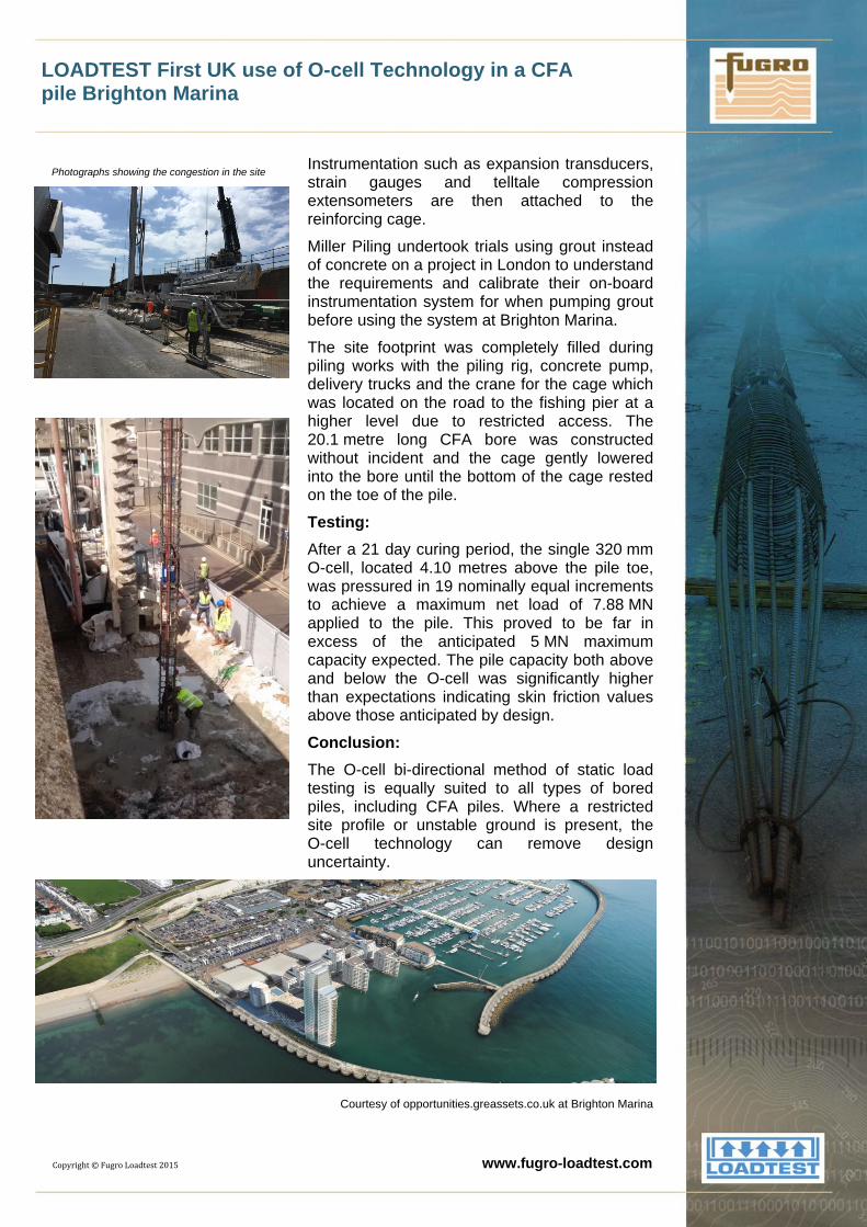
Photographs showing the congestion in the site
Instrumentation such as expansion transducers, strain gauges and telltale compression extensometers are then attached to the reinforcing cage.
Miller Piling undertook trials using grout instead of concrete on a project in London to understand the requirements and calibrate their on-board instrumentation system for when pumping grout before using the system at Brighton Marina.
The site footprint was completely filled during piling works with the piling rig, concrete pump, delivery trucks and the crane for the cage which was located on the road to the fishing pier at a higher level due to restricted access. The 20.1 metre long CFA bore was constructed without incident and the cage gently lowered into the bore until the bottom of the cage rested on the toe of the pile.
Testing:
After a 21 day curing period, the single 320 mm O-cell, located 4.10 metres above the pile toe, was pressured in 19 nominally equal increments to achieve a maximum net load of 7.88 MN applied to the pile. This proved to be far in excess of the anticipated 5 MN maximum capacity expected. The pile capacity both above and below the O-cell was significantly higher than expectations indicating skin friction values above those anticipated by design.
Conclusion:
The O-cell bi-directional method of static load testing is equally suited to all types of bored piles, including CFA piles. Where a restricted site profile or unstable ground is present, the O-cell technology can remove design uncertainty.
Courtesy of opportunities.greassets.co.uk at Brighton Marina
Copyright©FugroLoadtest2015 www.fugro-loadtest.com
Fugro GeoServices Ltd (LOADTEST Division) O-cell Technology in Cardiff, Wales
Project:
Location: Client:
Piling Contractor:
The Eastern Bay Link Project
Cardiff, Wales, UK Dawnus Ferrovial Joint Venture (DFJV) Bauer Technologies Ltd
Project Description:
Source: www.bbc.co.uk
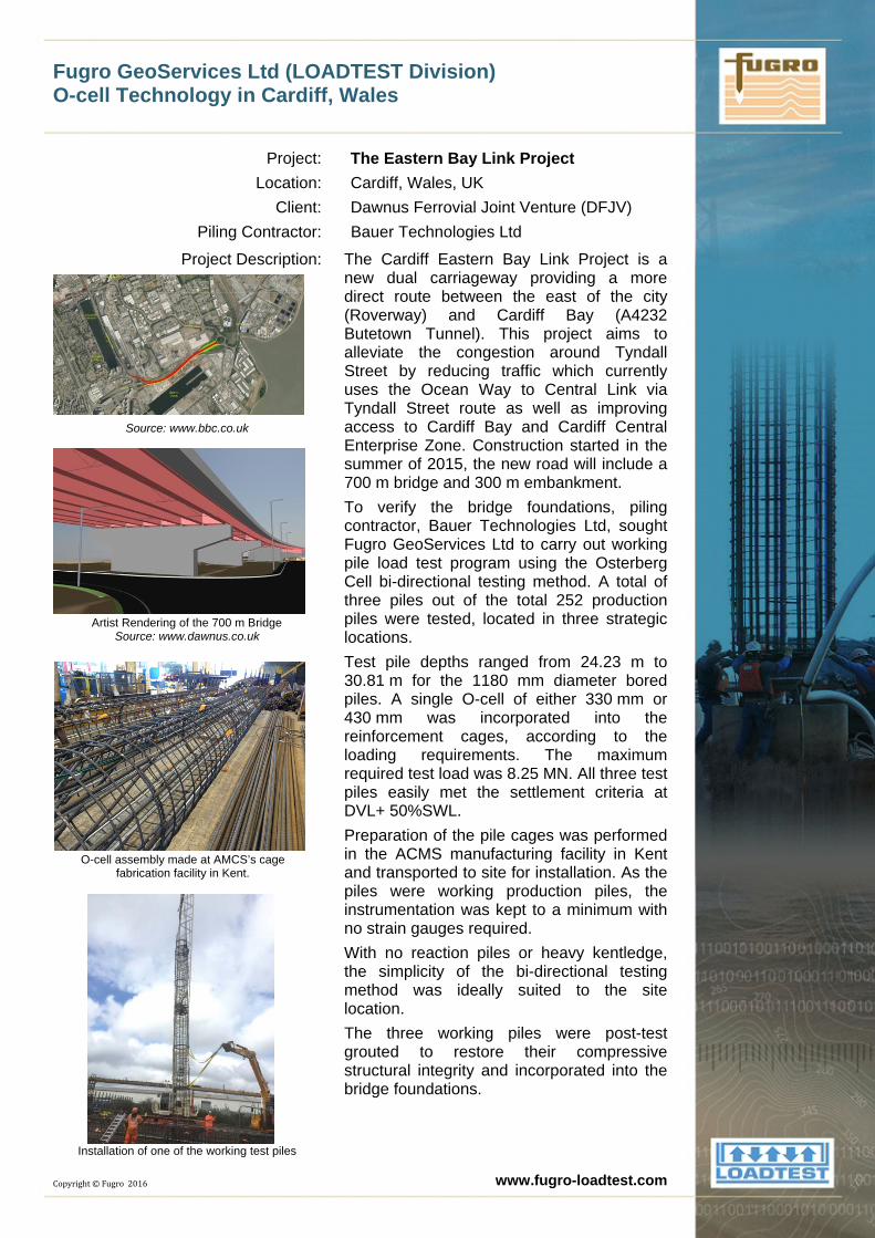
The Cardiff Eastern Bay Link Project is a new dual carriageway providing a more direct route between the east of the city (Roverway) and Cardiff Bay (A4232 Butetown Tunnel). This project aims to alleviate the congestion around Tyndall Street by reducing traffic which currently uses the Ocean Way to Central Link via Tyndall Street route as well as improving access to Cardiff Bay and Cardiff Central Enterprise Zone. Construction started in the summer of 2015, the new road will include a 700 m bridge and 300 m embankment.
Artist Rendering of the 700 m Bridge Source: www.dawnus.co.uk
O-cell assembly made at AMCS’s cage fabrication facility in Kent.
Installation of one of the working test piles
Copyright©Fugro2016
To verify the bridge foundations, piling contractor, Bauer Technologies Ltd, sought Fugro GeoServices Ltd to carry out working pile load test program using the Osterberg Cell bi-directional testing method. A total of three piles out of the total 252 production piles were tested, located in three strategic locations. Test pile depths ranged from 24.23 m to 30.81 m for the 1180 mm diameter bored piles. A single O-cell of either 330 mm or 430 mm was incorporated into the reinforcement cages, according to the loading requirements. The maximum required test load was 8.25 MN. All three test piles easily met the settlement criteria at DVL+ 50%SWL. Preparation of the pile cages was performed in the ACMS manufacturing facility in Kent and transported to site for installation. As the piles were working production piles, the instrumentation was kept to a minimum with no strain gauges required. With no reaction piles or heavy kentledge, the simplicity of the bi-directional testing method was ideally suited to the site location. The three working piles were post-test grouted to restore their compressive structural integrity and incorporated into the bridge foundations.
www.fugro-loadtest.com