Embed Size (px)
Citation preview
FUEL SYSTEM SERVICING
Refueling
The airplane may be fueled through a filler located in the top of each wing tank, through a filler in the top of the fuselage above the right engine, or through the single-point pressure filler (if installed) below the right engine.
Usable fuel, using the various refuel procedures, is given with the applicable procedure. Usable fuel valves may differ slightly from the chart values due to aircraft attitude at the time of refueling and other variables encountered in service.
WARNING: Ground fuel truck to apron and nose gear up-latch spacer and ground fuel nozzle to applicable ground jack prior to removing filler cap. This will help prevent possible fire and/or explosion due to static electricity or sparks.
NOTE: When refueling through the fuselage filler, reduced fuel flow rate may be required to avoid the possibility of a fuel spill or splash-back.
Fuel Tank Servicing
1. General
A. Fuel distribution should be such that during pressure fueling, the fuel level in both wings will be equal at all tines.
B. The airplane is normally fueled using the pressure fueling method. However, if pressure-fueling facilities are not available, overawing fill ports in the main tanks may be used. A pressure fueling station is located on the right aft fuselage under the engine. The fueling station contains the control panel for controlling and monitoring the pressure-fueling operation.
During any fueling operation, observe and follow all standard fueling precautions and practices.
2. Replenish Fue1 Tank (Pressure Method).
A. Ground airplane and fueling trucks.
WARNING: AIPPLANE AND FUEL TRUCK SH0ULD BE PROPERLY GROUNDED BEFORE ANY FUELING OPERATION TO PREVENT THE POSSIBILITY OF FIRE OR EXPLOSION DUE TO DISCHARGE OF STATIC ELECTRICITY.
B. Provide electrical power if necessary.
C. Open fueling station access doors and control panel access door.
D. Connect fueling nozzle ground plugs to grounding jacks.
E. Remove fueling receptacle caps and connect fueling nozzles.
F. Position the Refuel Selector Switch to either “TOTAL” or “PARTIAL” depending on the fuel order received by the flight crew.

G. Make sure the VENT OPEN LIGHT is on (green) before proceeding to fuel.
H. After the fuel is flowing, close the precheck valves (wing / fuselage). Fuel flow should stop within 10 seconds. If the fuel flow stops, turn the precheck switches back to normal and continue fueling. If the fuel flow does not stop, cease fueling and report it to the flight crew.
NOTE: All fueling nozzle pressures should be adjusted equally to 50 psi.
NOTE: Tanks to be completely filled will shut off automatically when full. When operation is complete, stop fueling source.
I. Disconnect. fueling nozzles, then disconnect nozzle grounding plugs.
K. Install fueling receptacle caps.
L. Close fueling station access doors.
M. Check that all fueling valve switches are in CLOSED position, then close fueling control panel door.
N. Disconnect fueling truck grounding cables.
O. Remove electrical power if no longer required.
Switch Fueling
Switch fueling is the practice of mixing fuels with a flash point of less than 100°F (38°C) with fuels having a flash point of more than 100°F (38°C). Mixing kerosene base, JP-5, Jet-A, Jet-A-1 or AVTUR fuels with wide cut petroleum distillates, JP-4, Jet-B, or AVTAG is considered switch fueling.
WARNING: Switch fueling changes the fuel/air mixture flammability characteristics. When switch fueling must be accomplished, fueling rates must be reduced to one-half the normal truck delivery rate in addition to observing the normal ground procedures.
NOTE: For additional information on the possible hazards of switch fueling, refer to FAA Order 8110.34, Advisory Circular AC 150/5230-3, and Advisory Circular AC 00-34A.
Fuel Anti-Ice Additive
CAUTION: On aircraft not equipped with fuel heaters, lack of anti-icing additive may cause fuel filter icing and subsequent engine flameout.
NOTE: On aircraft equipped with fuel heaters, for microbial protection, it is recommended that anti-icing additive be used, in the concentration specified, at least once a week for aircraft in regular use and whenever a fueled aircraft will be out of service for a week or more.
The wide range of temperatures to which jet fuels are exposed in flight result in substantial changes in the water solubility of the fuel. Some jet fuels have an anti-ice additive blended at the refinery and no additional fuel preparation is required prior to aircraft servicing. However, the majority of fuels do not contain anti-ice additive and additive conforming to MIL-I-27686 or MIL-I-85470 must be blended with these fuels during aircraft refueling. (Refer to FAA Approved Airplane Flight Manual.) The additive functions as a freeze-point-depressant and as a biocide. Its partitioning characteristics make it especially effective in nullifying the icing effects of small quantities of water in jet fuels. The second important characteristic of this jet fuel additive is its action as a biocidal agent which retards fungal and bacterial growth in fuel systems and fuel tanks.
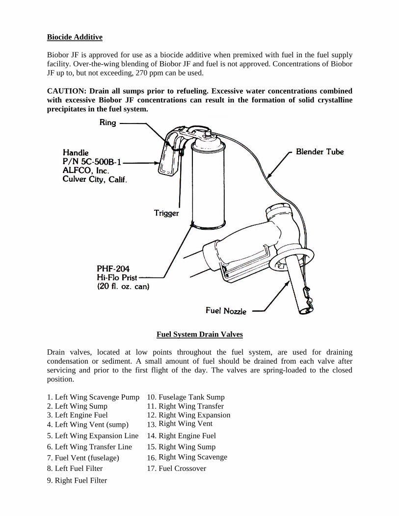
Biocide Additive
Biobor JF is approved for use as a biocide additive when premixed with fuel in the fuel supply facility. Over-the-wing blending of Biobor JF and fuel is not approved. Concentrations of Biobor JF up to, but not exceeding, 270 ppm can be used.
CAUTION: Drain all sumps prior to refueling. Excessive water concentrations combined with excessive Biobor JF concentrations can result in the formation of solid crystalline precipitates in the fuel system.
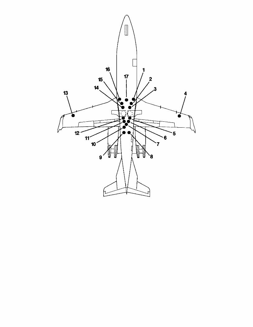
Fuel System Drain Valves
Drain valves, located at low points throughout the fuel system, are used for draining condensation or sediment. A small amount of fuel should be drained from each valve after servicing and prior to the first flight of the day. The valves are spring-loaded to the closed position.
1. Left Wing Scavenge Pump 10. Fuselage Tank Sump2. Left Wing Sump 11. Right Wing Transfer 3. Left Engine Fuel 12. Right Wing Expansion 4. Left Wing Vent (sump) 13. Right Wing Vent
(sump)5. Left Wing Expansion Line 14. Right Engine Fuel6. Left Wing Transfer Line 15. Right Wing Sump7. Fuel Vent (fuselage) 16. Right Wing Scavenge
Pump8. Left Fuel Filter 17. Fuel Crossover
9. Right Fuel Filter
OIL SYSTEM SERVICING
Service the engine lubrication system only with the oils listed in the APPROVED OILS list. (Refer to Addendum 11 - OIL SERVICING in the FAA Approved Airplane Flight Manual) Do not mix oils.
NOTE: Check the oil level immediately after engine shutdown. While the engine is inoperative, oil seeps from the tank into the gearbox. A false indication of low oil supply may be obtained if the level is checked after the engine has remained inoperative for a length of time.
Approved Oils
Service the engine lubrication system only with the oils listed in the APPROVED OILS list. (Refer to Addendum II - OIL SERVICING in the FAA Approved Airplane Flight Manual.) Do
Type II oils conforming to Pratt and Whitney Canada PWA521, are approved. (Refer to Addendum II - OIL SERVICING in the FAA Approved Airplane Flight Manual for a list of approved oils.)
Oil Level Check
WARNING: Areas in proximity of engine inlet and exhaust are extremely hazardous to personnel when engines are operating. Personnel shall clear these areas during engine start and operation to avoid injury.
NOTE: Check oil level 10 minutes after engine shutdown. If oil level is not checked 10 minutes after engine shutdown, start engine and allow to stabilize at idle. Shutdown engine and check oil level.
The engine oil servicing doors are located on the forward and outboard side of each engine nacelle and are opened by releasing the lever locks.
Oil level is checked with an oil dipstick incorporated into the oil filler cap. (Refer to Addendum II - OIL SERVICING in the FAA Approved Airplane Flight Manual.)
Adding Oil
Adding oil is accomplished by pouring oil into the oil filler tube (dipstick tube). The filler tube cap is removed by lifting and rotating the cap latch. (Refer to Addendum II - OIL SERVICING in the FAA Approved Airplane Flight Manual.)
TOILET SERVICING
A flushing toilet is installed in the lavatory compartment. The toilet assembly is designed for permanent installation and external servicing. External servicing may be accomplished through various methods, three of which will be discussed here.
CAUTION: When replenishing toilet paper dispenser, use only biodegradable toilet paper such as that used in recreational vehicles.
While servicing the toilet, any spillage should be cleaned immediately from contact with surrounding structure.
During freezing weather, add non-corrosive antifreeze to the flushing solution per label instructions.
Visual monitoring during clean fluid servicing is recommended.
Toilet Servicing Using Clean Flush Servicing Cart (P/N TSC-12)
1. Ensure toilet servicing cart has an adequate amount of fresh flushing fluid.2. Open gate valve on top of cart waste tank approximately 1/2 inch to prevent pressurizing
waste tank.3. On Clean Flush Servicing Cart installed with a vertically positioned valve:
a. Ensure vertically-positioned valve handle is perpendicular to the valve.b. Ensure horizontally-positioned valve handle is perpendicular to the valve.
On Clean Flush Servicing Cart not installed with a vertically positioned valve, ensure the valve handle is turned to the vertical position.
4. To connect servicing cart to aircraft, open service door on RH wing lower, forward fairing.5. Remove caps from connectors on aircraft service panel and connect servicing cart lines.6. Engage switch on aircraft service panel. Hold in position for approximately 15 seconds (this
starts the pump located in the toilet). Waste compartment contents are flushed to servicing cart waste tank. If momentary switch is released any time before servicing cycle is complete, servicing to the waste tank will stop instantly.
7. When the servicing cycle stops, release the switch on aircraft service panel.8. Pull the 5-amp TOILET circuit breaker located on the pilot's circuit breaker panel.9. Remove front toilet closure to prevent damage to panel.10. Lift the back of the seat cushion using the lifting strap and pull inboard to visually monitor clean fluid servicing.11. Turn servicing cart electrical power on. You will notice a short run of the pump.12. On Clean Flush Servicing Cart installed with a vertically positioned valve, turn valve handle of vertically-positioned valve parallel to the valve. Clean fluid fills toilet flushing fluid reservoir.On Clean Flush Servicing Cart not installed with a vertically positioned valve, turn valve handle parallel to the valve. Clean fluid fills toilet flushing fluid reservoir.13. When desired flushing fluid level is achieved, turn servicing cart electrical power off.14.On Clean Flush Servicing Cart installed with a vertically positioned valve, turn valve handle of vertically-positioned valve perpendicular to valve, and turn valve handle of horizontallypositioned valve parallel to valve to relieve pressure in clean fluid ne.15. Before disconnecting servicing cart lines, allow 1 to 2 minutes for excess fluids to drain back into servicing cart lines.
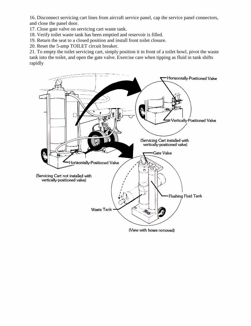
16. Disconnect servicing cart lines from aircraft service panel, cap the service panel connectors, and close the panel door.17. Close gate valve on servicing cart waste tank.18. Verify toilet waste tank has been emptied and reservoir is filled.19. Return the seat to a closed position and install front toilet closure.20. Reset the 5-amp TOILET circuit breaker.21. To empty the toilet servicing cart, simply position it in front of a toilet bowl, pivot the waste tank into the toilet, and open the gate valve. Exercise care when tipping as fluid in tank shifts rapidly

Toilet Servicing Using Tronair Servicing Unit (P/N 104036-0010)
1. Ensure lavatory servicing unit has adequate amount of fresh flushing fluid.2. Open service door on RH wing lower, forward fairing.3. Remove caps from connectors on aircraft service panel and connect servicing unit lines using
the lavatory adapter kit (fill coupling and dump coupling assemblies, P/N K-2288).4. Engage switch on aircraft service panel. Hold in position for approximately 15 seconds (this
starts the pump located in the toilet). Waste compartment contents are flushed to servicing unit waste tank. If momentary switch is released any time before servicing cycle is complete, servicing to the waste tank will stop instantly.
5. When the servicing cycle stops, release momentary switch on aircraft service panel.6. Pull the 5-amp TOILET circuit breaker located on the pilot's circuit breaker panel.7. Remove front toilet closure to avoid damage to panel.8. Lift the back of the seat cushion using the lifting strap and pull inboard to visually inspect
clean fluid servicing.9. Follow lavatory servicing unit operating instructions to fill flushing fluid reservoir.10. Return the seat to a closed position and install front toilet closure.11. Reset the 5-amp TOILET circuit breaker.12. Before disconnecting servicing unit lines, allow 1 to 2 minutes for excess fluids to drain back
into servicing unit lines.13. Disconnect servicing unit lines from aircraft service panel, remove the fill and dump
coupling adapter kit, cap the service panel connectors, and close the panel door.
Toilet Servicing Without A Toilet Servicing Cart
1. Open service door on RH wing lower, forward fairing.2. Remove cap from waste connector (large fitting) on aircraft service panel and connect short
length garden hose using the lavatory adapter kit dump coupling assembly (P/N TSC-12-3400), located in the aircraft.
3. The other end of the hose should be placed into a proper waste container.4. Engage switch on aircraft service panel. Hold in position for approximately 15 seconds (this
starts the pump located in the toilet). Waste compartment contents are flushed into the waste
container. If momentary switch is released any time before servicing cycle is complete, servicing to the waste tank will stop instantly.
5. When the servicing cycle stops, release momentary switch on aircraft service panel.6. Before disconnecting hose and adapter from aircraft, allow 1 to 2 minutes for excess fluids to
drain.7. Disconnect hose and adapter from aircraft service panel, cap the service panel waste
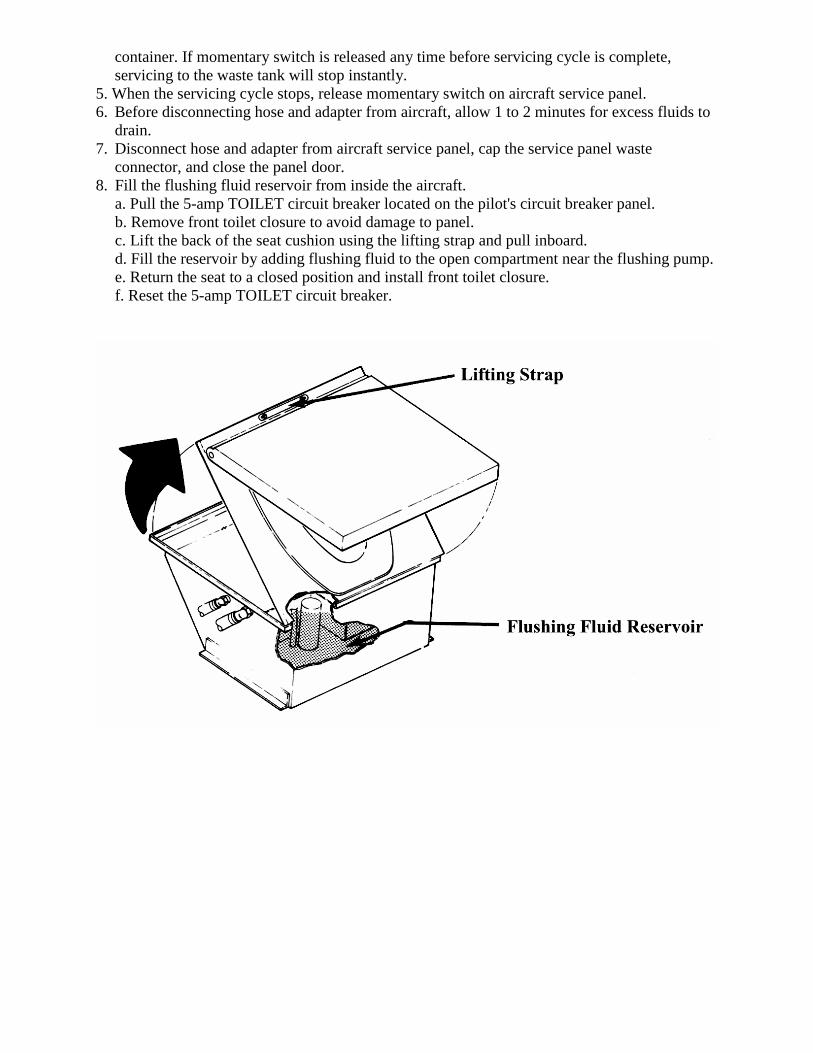
connector, and close the panel door.8. Fill the flushing fluid reservoir from inside the aircraft.
a. Pull the 5-amp TOILET circuit breaker located on the pilot's circuit breaker panel.b. Remove front toilet closure to avoid damage to panel.c. Lift the back of the seat cushion using the lifting strap and pull inboard.d. Fill the reservoir by adding flushing fluid to the open compartment near the flushing pump.e. Return the seat to a closed position and install front toilet closure.f. Reset the 5-amp TOILET circuit breaker.

POTABLE WATER SYSTEM
The potable water system is installed in the aft lavatory cabinet and consists of a potable water tank with an internal heater and water pump. The potable water tank is located below the sink in the aft lavatory. Periodic sanitation of the potable water system will vary with the environment in which the aircraft is operated. The frequency of sanitation shall be performed at the discretion of the aircraft operator.
CAUTION: If the aircraft will be subjected to freezing temperatures when parked, potable water tank must be removed.
Servicing
Remove Potable Water Tank1. Disengage quick-disconnect on potable water tank hose.2. Remove potable water tank by pulling straight out of cabinet.
Fill Potable Water Tank1. Remove snap plug from top of tank.2. Fill tank with potable water. Capacity of the water tank is 1.5 gallons (5.7 liters).3. Install snap plug in top of tank.
Install Potable Water Tank1. Install tank by pushing straight into compartment.2. Engage water hose quick-disconnect on potable water tank.3. Depress Pump Switch to ON and open water faucet to determine if connection was
properly engaged.4. Depress Pump Switch to OFF when water flows and close water faucet.
Servicing Under Freezing Conditions
Deactivate Potable Water System1. Remove potable water tank. Purge tank.2. Open faucet to pump water from lines.3. Depress Pump Switch to ON to purge water from lines.4. Depress Pump Switch to OFF.
Activate Potable Water System1. Install potable water tank.2. Depress Pump Switch to ON.3. Open faucet to purge air from lines.4. Depress Pump Switch to OFF when water flows.5. Close faucet.
External Power Receptacle
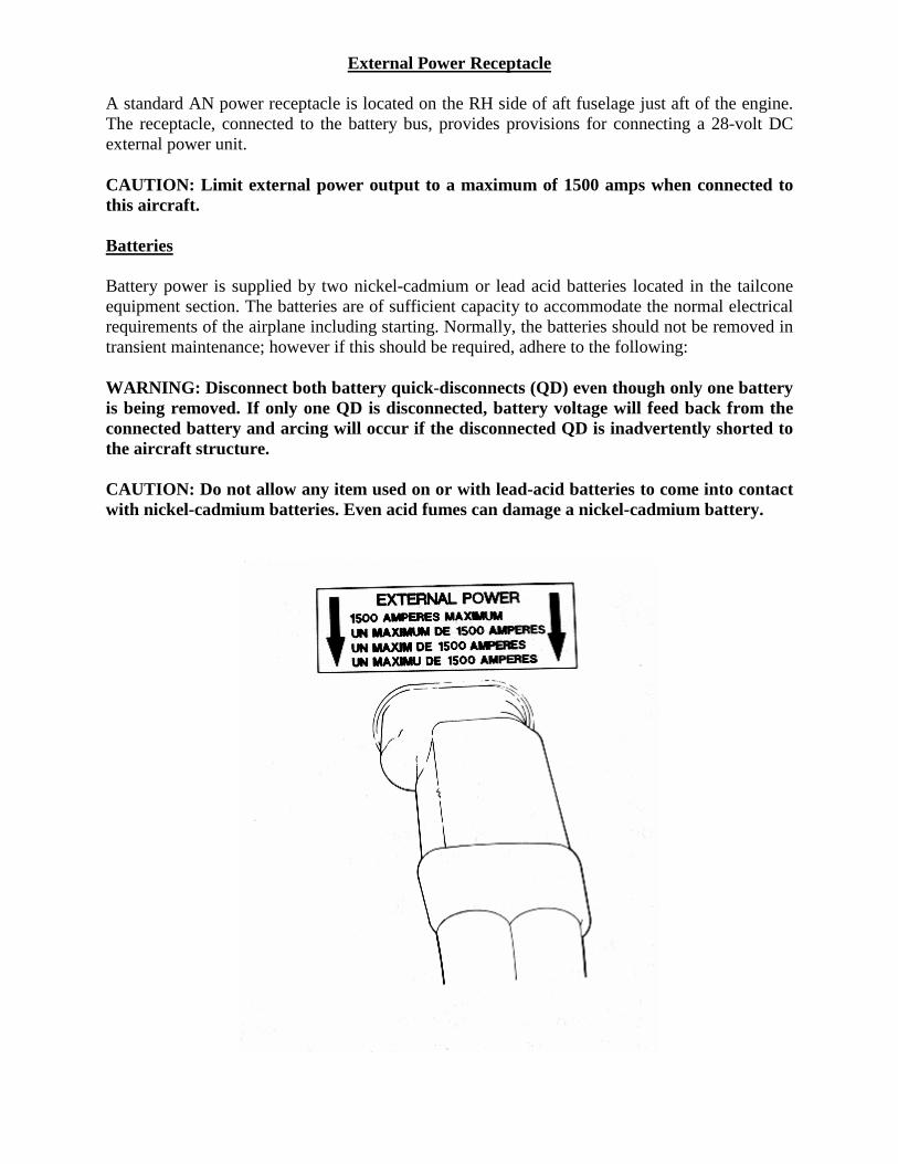
A standard AN power receptacle is located on the RH side of aft fuselage just aft of the engine.The receptacle, connected to the battery bus, provides provisions for connecting a 28-volt DC external power unit.
CAUTION: Limit external power output to a maximum of 1500 amps when connected to this aircraft.
Batteries
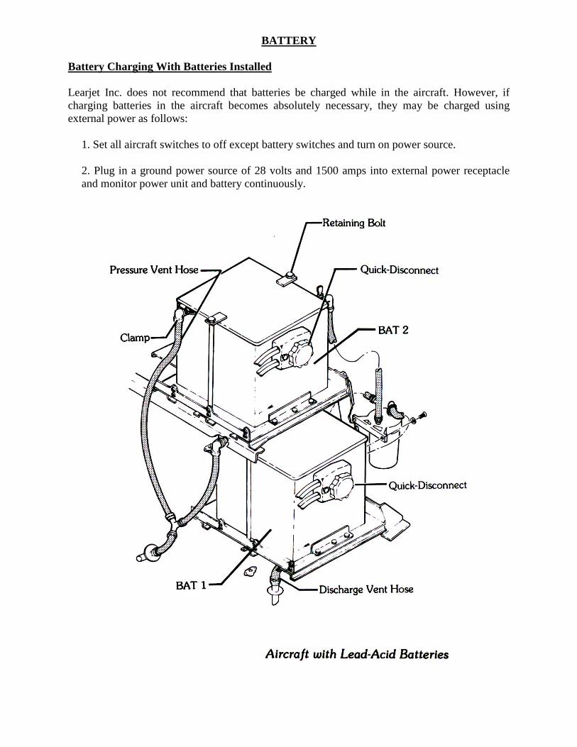
Battery power is supplied by two nickel-cadmium or lead acid batteries located in the tailcone equipment section. The batteries are of sufficient capacity to accommodate the normal electrical requirements of the airplane including starting. Normally, the batteries should not be removed in transient maintenance; however if this should be required, adhere to the following:
WARNING: Disconnect both battery quick-disconnects (QD) even though only one battery is being removed. If only one QD is disconnected, battery voltage will feed back from the connected battery and arcing will occur if the disconnected QD is inadvertently shorted to the aircraft structure.
CAUTION: Do not allow any item used on or with lead-acid batteries to come into contact with nickel-cadmium batteries. Even acid fumes can damage a nickel-cadmium battery.
BATTERY
Battery Charging With Batteries Installed
Learjet Inc. does not recommend that batteries be charged while in the aircraft. However, if charging batteries in the aircraft becomes absolutely necessary, they may be charged using external power as follows:
1. Set all aircraft switches to off except battery switches and turn on power source.
2. Plug in a ground power source of 28 volts and 1500 amps into external power receptacle and monitor power unit and battery continuously.
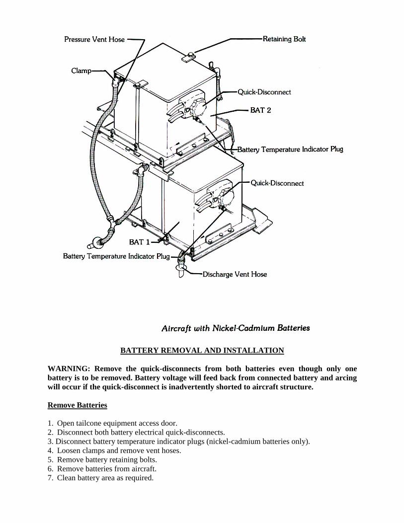
BATTERY REMOVAL AND INSTALLATION
WARNING: Remove the quick-disconnects from both batteries even though only one battery is to be removed. Battery voltage will feed back from connected battery and arcing will occur if the quick-disconnect is inadvertently shorted to aircraft structure.
Remove Batteries
1. Open tailcone equipment access door.2. Disconnect both battery electrical quick-disconnects.3. Disconnect battery temperature indicator plugs (nickel-cadmium batteries only).4. Loosen clamps and remove vent hoses.5. Remove battery retaining bolts.6. Remove batteries from aircraft.7. Clean battery area as required.
Install Batteries
1. Inspect batteries to assure no damage has occurred during shipment. If new batteries are being put into service, refer to Chapter 12 of the Maintenance Manual for servicing procedures.
CAUTION: Poor electrical contact could result in damage to the battery.
2. Position batteries in aircraft.3. Install bolts securing the batteries to battery shelf.4. Connect battery vent hoses to batteries. Secure hoses with clamps.5. Connect battery temperature indicator plugs (nickel-cadmium batteries only).6. Connect battery electrical quick-disconnects.7. Close tailcone access door.
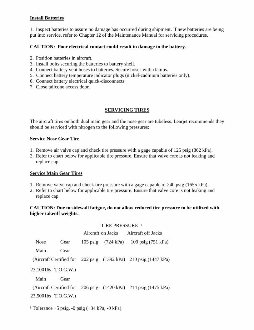
SERVICING TIRES
The aircraft tires on both dual main gear and the nose gear are tubeless. Learjet recommends they should be serviced with nitrogen to the following pressures:
Service Nose Gear Tire
1. Remove air valve cap and check tire pressure with a gage capable of 125 psig (862 kPa).2. Refer to chart below for applicable tire pressure. Ensure that valve core is not leaking and
replace cap.
Service Main Gear Tires
1. Remove valve cap and check tire pressure with a gage capable of 240 psig (1655 kPa).2. Refer to chart below for applicable tire pressure. Ensure that valve core is not leaking and
replace cap.
CAUTION: Due to sidewall fatigue, do not allow reduced tire pressure to be utilized with higher takeoff weights.
TIRE PRESSURE ¹Aircraft on Jacks Aircraft off Jacks
Nose Gear 105 psig (724 kPa) 109 psig (751 kPa)
Main Gear
(Aircraft Certified for 202 psig (1392 kPa) 210 psig (1447 kPa)
23,10016s T.O.G.W.)
Main Gear
(Aircraft Certified for 206 psig (1420 kPa) 214 psig (1475 kPa)
23,5001bs T.O.G.W.)
¹ Tolerance +5 psig, -0 psig (+34 kPa, -0 kPa)
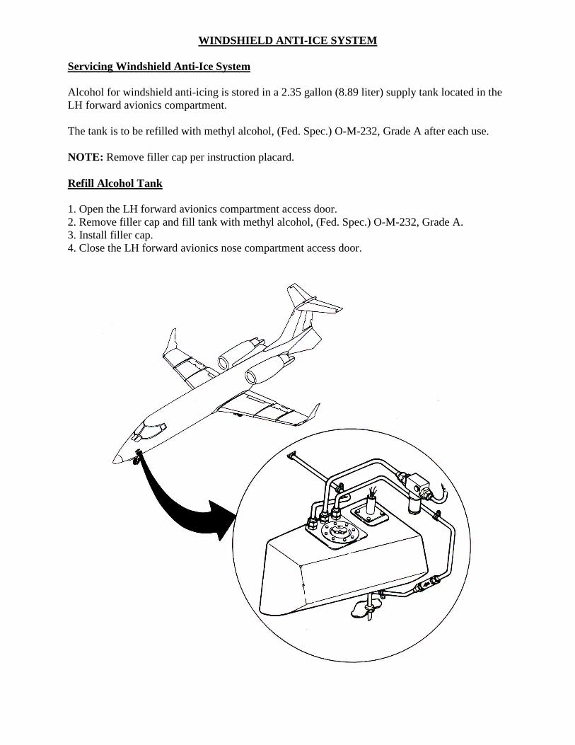
WINDSHIELD ANTI-ICE SYSTEM
Servicing Windshield Anti-Ice System
Alcohol for windshield anti-icing is stored in a 2.35 gallon (8.89 liter) supply tank located in the LH forward avionics compartment.
The tank is to be refilled with methyl alcohol, (Fed. Spec.) O-M-232, Grade A after each use.
NOTE: Remove filler cap per instruction placard.
Refill Alcohol Tank
1. Open the LH forward avionics compartment access door.2. Remove filler cap and fill tank with methyl alcohol, (Fed. Spec.) O-M-232, Grade A.3. Install filler cap.4. Close the LH forward avionics nose compartment access door.

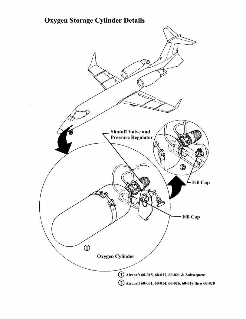
SERVICING OXYGEN SYSTEM
WARNING: Prior to servicing the oxygen system, personnel should familiarize themselves with and strictly adhere to safety precautions.
The oxygen storage cylinder is located in the nose LH aft avionics compartment (An optional cylinder may be located in the dorsal).
If the oxygen storage cylinder has been thermally discharged, remove the cylinder and replace washer and burst disc. The discharge indicator must be replaced prior to installing oxygen storage cylinder.
The regulator does not normally need to be closed. However, when servicing the oxygen system, verify that the regulator is open prior to returning the aircraft to service.
WARNING: Use only dry breathing oxygen, Federal Specification MIL-O-27210, Type I, from a green colored cylinder.
Safety Precautions
Servicing the oxygen system requires strict adherence to the following precautions.
WARNING: Do not permit smoking or open flame in or near aircraft while servicing is being performed on the oxygen system. Ensure all electrical power is disconnected from aircraft and that the aircraft is properly grounded. Oils, grease, and solvent may burn orexplode spontaneously when contacted by oxygen under pressure. Be sure hands and clothing are free of grease and oil.
Charge Oxygen Storage Cylinder
NOTE: The following procedure discusses the oxygen cylinder located in the LH aft avionics compartment. This procedure is also applicable for aircraft equipped with an oxygen cylinder located in the dorsal, with the exception of its location.
1. Open nose LH aft avionics compartment access door.2. Remove fill cap and attach oxygen supply to fill valve.
WARNING: Rapid charging of oxygen system will create a dangerous overheat condition in oxygen storage cylinder. Use only dry breathing oxygen, Federal Specification MIL-O-27210, Type I, from a green colored cylinder.
NOTE: Slight leakage may be detected when the fill cap is removed.
3. Open supply tank valve and slowly charge oxygen system to pressure specified in table below.
4. Close supply line valve and disconnect supply line.5. Install fill valve cap on fill valve. Tighten cap, using care when torquing to prevent stripping
of threads.6. Using CG Leak Detector Fluid, leak test fill valve cap.7. Verify that shutoff valve and regulator assembly is open.8. Close nose LH aft avionics compartment access door.
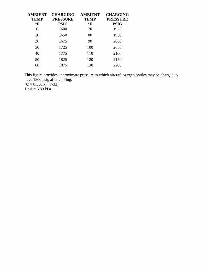
AMBIENTTEMP
°F
CHARGINGPRESSURE
PSIG
AMBIENTTEMP
°F
CHARGINGPRESSURE
PSIG0 1600 70 192510 1650 80 195020 1675 90 200030 1725 100 205040 1775 110 210050 1825 120 215060 1875 130 2200
This figure provides approximate pressure to which aircraft oxygen bottles may be charged to have 1800 psig after cooling.°C = 0.556 x (°F-32)1 psi = 6.89 kPa