Embed Size (px)
Citation preview
MAJOR POWER MAJOR
[SUPPLEMENT
FUEL
SECTION 2
SYSTEM
,----BLEED SCREW INJECTOR\-
FUEL OIL FILTER
BLEED SCREW 7
FUEL LIFT PUMP -INJECTION PUMP
HAND PRIMING LEVER
PNEUMATIC GOVERNOR
-DAMPING VALVE ADJUSTER
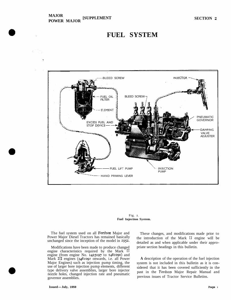
Fig. I. Fuel Injection System.
The fuel system used on all Fordson Major and Power Major Diesel Tractors has remained basically unchanged since the inception of the model in 1952.
Modifications have been made to produce changed engine characteristics required by the Mark I1 engine (from engine No. 1425097 to 1481090) and Mark I11 engines (1481091 onwards, i.e. all Power Major Engines) such as injection pump timing, the use of larger bore injection pump elements, different type delivery valve assemblies, larger bore injector nozzle holes, changed injection rate and pneumatic governor assemblies.
These changes, and modifications made prior to the introduction of the Mark I1 engine will be detailed as and when applicable under their appro- priate section headings in this bulletin.
A description of the operation of the fuel injection system is not included in this bulletin as it is con- sidered that it has been covered sufficiently in the past in the Fordson Major Repair Manual and previous issues of Tractor Service Bulletins.
Issued-July, 1959 Page I
MAJOR 1 SUPPLEMENT POWER MAJOR
SECTION 2
ROUTINE SERVICING OF THE FUEL SYSTEM
FUEL LIFT PUXP FILTER
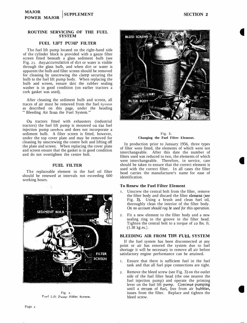
The fuel lift pump located on the right-hand side of the cylinder block is provided with a gauze filter screen fitted beneath a glass sediment bulb (see Fig. 2). Anygccumulation of dirt or water is visible through the glass bulb, and when dirt or water is apparent the bulb and filter screen should be removed for cleaning by unscrewing the clamp securing the bulb to the fuel lift pump body. When replacing the bulb and screen, ensure that the rubber sealing washer is in good condition (on earlier tractors a cork gasket was usedj.
After cleaning the sediment bulb and screen, all traces of air must be removed from the fuel system as described on this page, under the heading " Bleeding Air from the Fuel System."
On tractors fitted with exhausters (industrial tractors) the fuel lift pump is mounred oil the fuel injection pump cambox and does not incorporate a sediment bulb. A filter screen is fitted, however, under the top cover plate and may be removed for cleaning by unscrewing the centre bolt and lifting off the plate and screen. When replacing the cover plate and screen ensure that the gasket is in good condition and do not overtighten the centre bolt.
FUEL FILTER
The replaceable element in the fuel oil filter should be renewed at intervals not exceeding 600 working hours.
Fig. 2.
F w t Lift Pump Filfet Screen.
Fig. 3 . Changing the Fuel Filter Element.
In production prior to January 1956, three types of filter were fitted, the elements of which were not interchangeable. After this date the number of filters used was reduced to two, the elements of which were interchangeable. Therefore, in service, care should be taken to ensure that the correct element is used with the correct filter. In all cases the filter head carries the manufacturer's name for ease of identification.
To Renew the Fuel Filter Element I . Unscrew the central bolt from the filter. remove
the filter body and discard the filter elekent (see Fig. 3). Using a brush and clean fuel oil, thoroughly clean the interior of the filter body. On no account should rag be used for this operation.
2. Fit a new element to the filter body and a new sealing ring to the groove in the filter head. Tighten the central bolt to a torque of 10 lbs. ft. (1.38 kg.m.).
BLEEDING AIR FROM THE FUEL SYSTEM If the fuel system has been disconnected at any
point or air has entered the system due to fuel shortage it will be necessary to remove all air before satisfactory engine performance can be attained.
I . Ensure that there is sufficient fuel in the fuel tank and that all fuel pipe connections are tight.
2. Remove the bleed screw (see Fig. 3) on the outlet side of the fuel filter head (the one nearest the fuel injection pump) and operate the priming lever on the fuel lift oumD. Continue D U ~ D ~ ~ E until a strezm of fiel, &ee from air 'bubhec issues from the filter. Replace and tighten the bleed screw.
Page 2
MAJOR l SUPPLEMENT POWER MAJOR j
SECTION 2
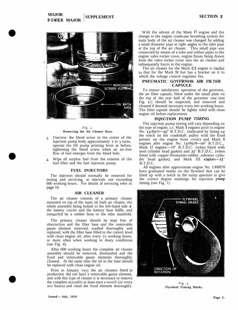
Fig. 4. Removing the Air Cleaner Base.
3. Unscrew the bleed screw in the centre of the injection pump body approximately 2 to 3 turns, operate the lift pump priming lever as before, tightening the bleed screw when an air-free flow of fuel emerges from the bleed hole.
4. Wipe all surplus fuel from the exterior of the fuel filter and the fuel injection pump.
FUEL INJECTORS The injectors should normally be removed for
testing and servicing, at intervals not exceeding 600 working hours. For details of servicing refer to nape 16. 1 0
AIR CLEANER The air cleaner consists of a primary cleaner
mounted on top of the main oil bath air cleaner, the whole assembly being bolted to the left-hand side of the battery carrier and the battery heat baffle, and connezted by a rubber hose to the inlet manifold.
The primary cleaner should be kept free of obstruction and the filter base and the removable gauze element removed, washed thoroughly and replaced, with the filter base filled to the correct level with clean engine oil, after every 50 working hours, or more often when working in dusty conditions (see Fig. 4).
After 600 working hours the complete air cleaner assembly should be removed, dismantled and the fixed and removable gauze elements thoroughly cleaned. At the same time the oil in the base should be replaced with clean engine oil.
Prior to January 1955 the air cleaners fitted in production did not have a removable gauze element, and with this type of cleaner it is necessary to remove the complete assembly at least once a monih (or every 200 hours) and clean the fixed element thoroughly.
With the advent of the Mark I1 engine and the change to the engine crankcase breathing system the main body of the air cleaner was changed by adding a small diameter pipe at right angles to the inlet pipe at the top of thc. air cleaner. This small pipe was connected by means of a tube and rubber pipes to the engine valve rocker cover, engine fumes being drawn from the valve rocker cover into the air cleaner and subsequently burnt in the engine.
The air cleaner for the Mark I11 engine is similar ro that for the Mark 11 but has a bracket on it to which the voltage control regulator fits.
PNEUMATIC GOVERNOR AIR FILTER CAPSULE
To ensure satisfactory operation of the governor, the air filter capsule, fitted under the small plate on the top of the rear half of the governor case (see Fig. 10) should be inspected, and removed and cleaned if deemed necessary every 200 working hours. The filter capsule should be lightly oiled with clean engine oil before replacement.
INJECTION PUMP "FZMmG The injection pump timing will vary depending on
the type of engine, i.e. Mark I engines prior to engine No. 1308977-29' B.T.D.C. (indicated by lining up the notch on the crankshaft pulley with the fixed pointer on the engine front cover) and Mark H engines after engine No. 1308978-2g0 B.T.D.C., Mark I1 engines-19" B.T.D.C. (when fitted with steel cylinder head gasket) and 23" B.T.D.C. (when fitted with copper-Permanite-rubber asbestos cylin- der head gasket). and Mark 111 engines-23" B.T.D.C.
All engines after approximate engine No. 1308978 have graduated marks on the flywheel that can be lined up with a notch in the sump aperture to give the correct degree markings for injection pump timing (see Fig. 5 ) .
Fig. 5. Flywheel Timing Marks.
Issued-July, 1959 Page 3 .
MAJOR POWER MAJOR
/SUPPLEMENT SECTION 2
Checking and Adjusting Injection P u m p Timing I. Move the inspection cover on the right-hand
side of the sump flywheel housmg to one side and turn the engine until wlth No. I piston on its compression stroke (this can be checked by removing the oil filler cap and observing the operation of the valves), the correct degree marking for the type of engine is in line wlth the index notch on the side of the inspection aperture (see Fig. 5 ) .
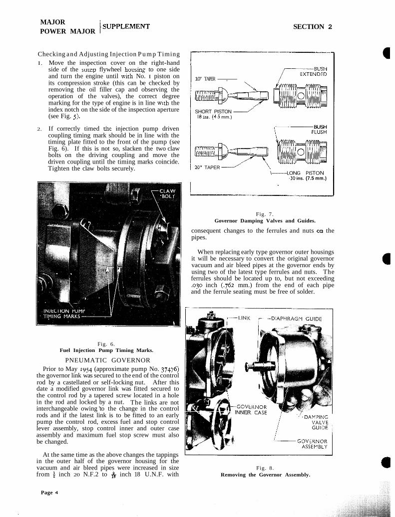
2. If correctly timed injection pump driven coupling timing mark should be in line with the timing plate fitted to the front of the pump (see Fig. 6). If this is not so, slacken the two claw bolts on the driving coupling and move the driven coupling until the timing marks coincide. Tighten the claw bolts securely.
Fig. 6. Fuel Injection Pump Timing Marks.
PNEUMATIC GOVERNOR Prior to May 1954 (approximate pump No. 37476)
the governor link was secured to the end of the control rod by a castellated or self-locking nut. After this date a modified governor link was fitted secured to the control rod by a tapered screw located in a hole in the rod and locked by a nut. The links are not interchangeable owing 'to the change in the control rods and if the latest link is to be fitted to an early pump the control rod, excess fuel and stop control lever assembly, stop control inner and outer case assembly and maximum fuel stop screw must also be changed.
At the same time as the above changes the tappings in the outer half of the governor housing for the vacuum and air bleed pipes were increased in size from 6 inch 20 N.F.2 to & inch 18 U.N.F. with
BUSH
10" TAPER-, /YNDED
I SHORT PISTON / ---v- .
I l 8 ins. ( 4 5 mm.)
BUSH F L U S H
1 20" TAPER ---l \ "- \-----LONG PISTON
.30 ins. (7.5 mm.)
Fig. 7. Governor Damping Valves and Guides.
consequent changes to the ferrules and nuts on the pipes.
When replacing early type governor outer housings it will be necessary to convert the original governor vacuum and air bleed pipes at the governor ends by using two of the latest type ferrules and nuts. The ferrules should be located up to, but not exceeding .o30 inch (.762 mm.) from the end of each pipe and the ferrule seating must be free of solder.
INNER t A C F
Fig. 8. Removing the Governor Assembly.
Page 4
MAJOR 1 SUPPLEMENT POWER MAJOR
SECTION 2
GOVERNOR S P R I N G 7
DAMPING VALVE ------\ \ DlAPH RAGM
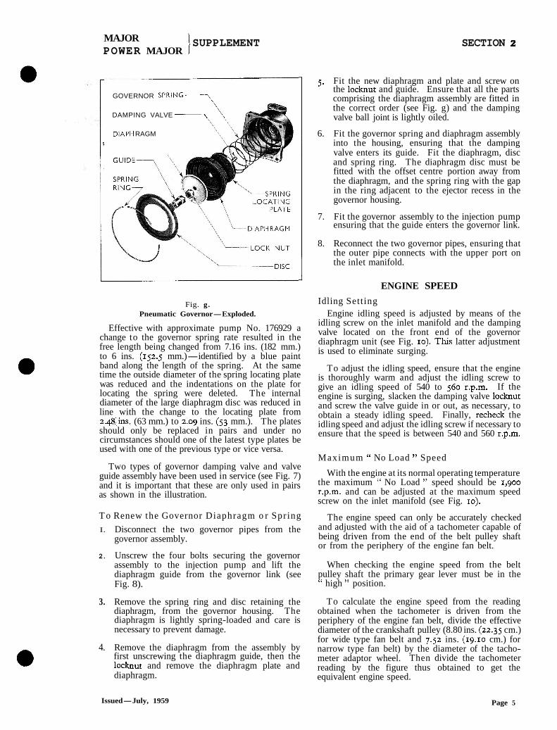
Fig. g. Pneumatic Governor-Exploded.
Effective with approximate pump No. 176929 a change to the governor spring rate resulted in the free length being changed from 7.16 ins. (182 mm.) to 6 ins. (152.5 mm.)-identified by a blue paint band along the length of the spring. At the same time the outside diameter of the spring locating plate was reduced and the indentations on the plate for locating the spring were deleted. The internal diameter of the large diaphragm disc was reduced in line with the change to the locating plate from 2.48.1ns. (63 mm.) to 2.09 ins. (53 mm.). The plates should only be replaced in pairs and under no circumstances should one of the latest type plates be used with one of the previous type or vice versa.
Two types of governor damping valve and valve guide assembly have been used in service (see Fig. 7) and it is important that these are only used in pairs as shown in the illustration.
T o Renew the Governor Diaphragm o r Spring
I. Disconnect the two governor pipes from the governor assembly.
2. Unscrew the four bolts securing the governor assembly to the injection pump and lift the diaphragm guide from the governor link (see Fig. 8).
3. Remove the spring ring and disc retaining the diaphragm, from the governor housing. The diaphragm is lightly spring-loaded and care is necessary to prevent damage.
4. Remove the diaphragm from the assembly by first unscrewing the diaphragm guide, then the locknut and remove the diaphragm plate and diaphragm.
5. Fit the new diaphragm and plate and screw on the locknut and guide. Ensure that all the parts comprising the diaphragm assembly are fitted in the correct order (see Fig. g) and the damping valve ball joint is lightly oiled.
6. Fit the governor spring and diaphragm assembly into the housing, ensuring that the damping valve enters its guide. Fit the diaphragm, disc and spring ring. The diaphragm disc must be fitted with the offset centre portion away from the diaphragm, and the spring ring with the gap in the ring adjacent to the ejector recess in the governor housing.
7. Fit the governor assembly to the injection pump ensuring that the guide enters the governor link.
8. Reconnect the two governor pipes, ensuring that the outer pipe connects with the upper port on the inlet manifold.
ENGINE SPEED
Idling Setting Engine idling speed is adjusted by means of the
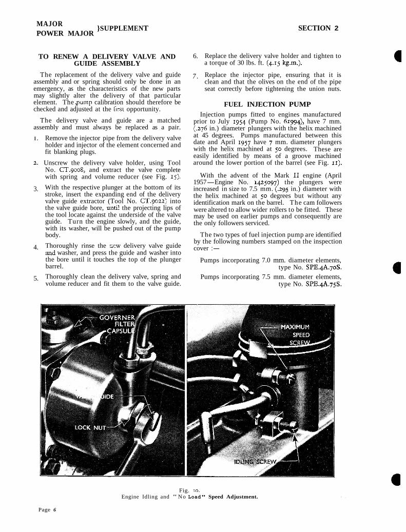
idling screw on the inlet manifold and the damping valve located on the front end of the governor diaphragm unit (see Fig. 10). T h s latter adjustment is used to eliminate surging.
To adjust the idling speed, ensure that the engine is thoroughly warm and adjust the idling screw to give an idling speed of 540 to 560 r.p.m. If the engine is surging, slacken the damping valve locknut and screw the valve guide in or out, as necessary, to obtain a steady idling speed. Finally, recheck the idling speed and adjust the idling screw if necessary to ensure that the speed is between 540 and 560 r.p.m.
Maximum " No Load " Speed
With the engine at its normal operating temperature the maximum " No Load " speed should be 1,900 r.p.m. and can be adjusted at the maximum speed screw on the inlet manifold (see Fig. 10).
The engine speed can only be accurately checked and adjusted with the aid of a tachometer capable of being driven from the end of the belt pulley shaft or from the periphery of the engine fan belt.
When checking the engine speed from the belt pulley shaft the primary gear lever must be in the " high " position.
To calculate the engine speed from the reading obtained when the tachometer is driven from the periphery of the engine fan belt, divide the effective diameter of the crankshaft pulley (8.80 ins. (22.35 cm.) for wide type fan belt and 7.52 ins. (19.10 cm.) for narrow type fan belt) by the diameter of the tacho- meter adaptor wheel. Then divide the tachometer reading by the figure thus obtained to get the equivalent engine speed.
Issued-July, 1959 Page 5
MAJOR POWER MAJOR
}SUPPLEMENT SECTION 2
TO RENEW A DELIVERY VALVE AND GUIDE ASSEMBLY
The replacement of the delivery valve and guide assembly and or spring should only be done in an emergency, as the characteristics of the new parts may slightly alter the delivery of that particular element. The gump calibration should therefore be checked and adjusted at the first opportunity.
The delivery valve and guide are a matched assembly and must always be replaced as a pair.
I. Remove the injector pipe from the delivery valve holder and injector of the element concerned and fit blanking plugs.
2. Unscrew the delivery valve holder, using Tool No. CT.9008, and extract the valve complete with spring and volume reducer (see Fig. 15).
3. With the respective plunger at the bottom of its stroke, insert the expanding end of the delivery valve guide extractor (Tool No. CT.9022) into the valve guide bore, un t~ l the projecting lips of the tool locate against the underside of the valve guide. Turn the engine slowly, and the guide, with its washer, will be pushed out of the pump body.
4. Thoroughly rinse the r,ew delivery valve guide and washer, and press the guide and washer into the bore until it touches the top of the plunger barrel.
5. Thoroughly clean the delivery valve, spring and volume reducer and fit them to the valve guide.
6. Replace the delivery valve holder and tighten to a torque of 30 lbs. ft. (4.15 kg.m.).
7 . Replace the injector pipe, ensuring that it is clean and that the olives on the end of the pipe seat correctly before tightening the union nuts.
FUEL INJECTION PUMP Injection pumps fitted to engines manufactured
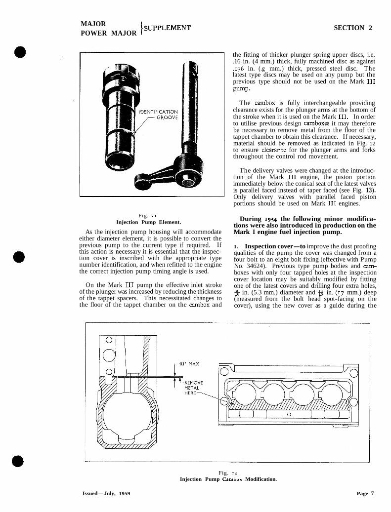
prior to July 1954 (Pump No. 61994), have 7 mm. (.276 in.) diameter plungers with the helix machined at 45 degrees. Pumps manufactured between this date and April 1957 have 7 mm. diameter plungers with the helix machined at 50 degrees. These are easily identified by means of a groove machined around the lower portion of the barrel (see Fig. 11).
With the advent of the Mark I1 engine (April 1957-Engine No. 1425097) the plungers were increased in size to 7.5 mm. (.295 in.) diameter with the helix machined at 50 degrees but without any identification mark on the barrel. The cam followers were altered to allow wider rollers to be fitted. These may be used on earlier pumps and consequently are the only followers serviced.
The two types of fuel injection pump are identified by the following numbers stamped on the inspection cover :-
Pumps incorporating 7.0 mm. diameter elements, type No. SPE.4A.pS.
Pumps incorporating 7.5 mm. diameter elements, type No. SPE.qA.75S.
Fig. 10. Engine Idling and " N o Load" Speed Adjustment.
Page 6
MAJOR POWER MAJOR
}SUPPLEMENT SECTION 2
Fig. 1 1 .
Injection Pump Element.
As the injection pump housing will accommodate either diameter element, it is possible to convert the previous pump to the current type if required. If this action is necessary it is essential that the inspec- tion cover is inscribed with the appropriate type number identification, and when refitted to the engine the correct injection pump timing angle is used.
On the Mark I11 pump the effective inlet stroke of the plunger was increased by reducing the thickness of the tappet spacers. This necessitated changes to the floor of the tappet chamber on the cambox and
the fitting of thicker plunger spring upper discs, i.e. .16 in. (4 mm.) thick, fully machined disc as against ,036 in. (.g mm.) thick, pressed steel disc. The latest type discs may be used on any pump but the previous type should not be used on the Mark I11
The cambox is fully interchangeable providing clearance exists for the plunger arms at the bottom of the stroke when it is used on the Mark 111. In order to utilise previous design camboxes it may therefore be necessary to remove metal from the floor of the tappet chamber to obtain this clearance. If necessary, material should be removed as indicated in Fig. 12 to ensure clearar-re for the plunger arms and forks throughout the control rod movement.
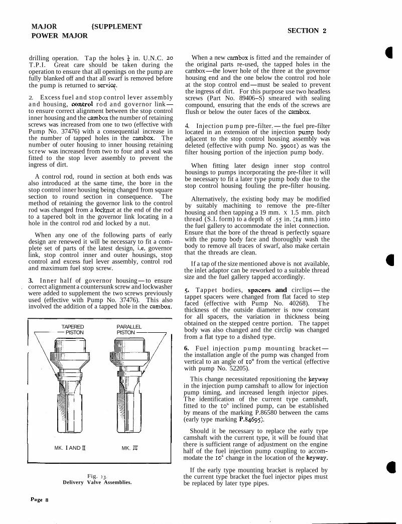
The delivery valves were changed at the introduc- tion of the Mark 111 engine, the piston portion immediately below the conical seat of the latest valves is parallel faced instead of taper faced (see Fig. 13). Only delivery valves with parallel faced piston portions should be used on Mark I11 engines.
During 1954 the following minor modifica- tions were also introduced in production on the Mark I engine fuel injection pump.
I. Inspection cover-to improve the dust proofing qualities of the pump the cover was changed from a four bolt to an eight bolt fixing (effective with Pump No. 34624). Previous type pump bodies and cam- boxes with only four tapped holes at the inspection cover location may be suitably modified by fitting one of the latest covers and drilling four extra holes, & in. (5.3 mm.) diameter and in. (17 mm.) deep (measured from the bolt head spot-facing on the cover), using the new cover as a guide during the
Fig. 12. Injection Pump Cambox Modification.
Issued-July, 1959 Page 7
MAJOR {SUPPLEMENT POWER MAJOR
SECTION 2
drilling operation. Tap the holes % in. U.N.C. 20 T.P.I. Great care should be taken during the operation to ensure that all openings on the pump are fully blanked off and that all swarf is removed before the pump is returned to serviy
2. Excess fuel and s top control lever assembly a n d housing, w n t r o l r o d and governor link- to ensure correct alignment between the stop control inner housing and the cambox the number of retaining screws was increased from one to two (effective with Pump No. 37476) with a consequential increase in the number of tapped holes in the cambox. The number of outer housing to inner housing retaining screw was increased from two to four and a seal was fitted to the stop lever assembly to prevent the ingress of dirt.
A control rod, round in section at both ends was also introduced at the same time, the bore in the stop control inner housing being changed from square section to round section in consequence. The method of retaining the governor link to the control rod was changed from a locknut at the end of the rod to a tapered bolt in the governor link locating in a hole in the control rod and locked by a nut.
When any one of the following parts of early design are renewed it will be necessary to fit a com- plete set of parts of the latest design, i.e. governor link, stop control inner and outer housings, stop control and excess fuel lever assembly, control rod and maximum fuel stop screw.
3. Inner half of governor housing-to ensure L correct alignment a countersunk screw and lockwasher
were added to supplement the two screws previously used (effective with Pump No. 37476). This also involved the addition of a tapped hole in the cambox.
I TAPERED PARALLEL PISTON PISTON --------l
MK. I AND I1 MK. IlI
Fig. 13. Delivery Valve Assemblies.
When a new cambox is fitted and the remainder of the original parts re-used, the tapped holes in the cambox-the lower hole of the three at the governor housing end and the one below the control rod hole at the stop control end-must be sealed to prevent the ingress of dirt. For this purpose use two headless screws (Part No. 89406-S) smeared with sealing compound, ensuring that the ends of the screws are flush or below the outer faces of the cambox.
4. Injection p u m p pre-filter.-the fuel pre-filter located in an extension of the injection pump body adjacent to the stop control housing assembly was deleted (effective with pump No. 39001) as was the filter housing portion of the injection pump body.
When fitting later design inner stop control housings to pumps incorporating the pre-filter it will be necessary to fit a later type pump body due to the stop control housing fouling the pre-filter housing.
Alternatively, the existing body may be modified by suitably machining to remove the pre-filter housing and then tapping a 19 mm. X 1.5 mm. pitch thread (S.I. form) to a depth of .55 in. (14 mm.) into the fuel gallery to accommodate the inlet connection. Ensure that the bore of the thread is perfectly square with the pump body face and thoroughly wash the body to remove all traces of swarf, also make certain that the threads are clean.
If a tap of the size mentioned above is not available, the inlet adaptor can be reworked to a suitable thread size and the fuel gallery tapped accordingly.
5. Tappet bodies, spacess and circlips-the tappet spacers were changed from flat faced to step faced (effective with Pump No. 40268). The thickness of the outside diameter is now constant for all spacers, the variation in thickness being obtained on the stepped centre portion. The tappet body was also changed and the circlip was changed from a flat type to a dished type.
6. Fuel injection p u m p mounting bracket- the installation angle of the pump was changed from vertical to an angle of 10" from the vertical (effective with pump No. 52205).
This change necessitated repositioning the keyway in the injection pump camshaft to allow for injection pump timing, and increased length injector pipes. The identification of the current type camshaft, fitted to the 10" inclined pump, can be established by means of the marking P.86580 between the cams (early type marking P.84695).
Should it be necessary to replace the early type camshaft with the current type, it will be found that there is sufficient range of adjustment on the engine half of the fuel injection pump coupling to accom- modate the 10" change in the location of the keyway.
If the early type mounting bracket is replaced by the current type bracket the fuel injector pipes must be replaced by later type pipes.
Page 8
MAJOR POWER MAJOR
1 SUPPLEMENT
I CONTROL FORK I
CONTROL ROD FORKS 1
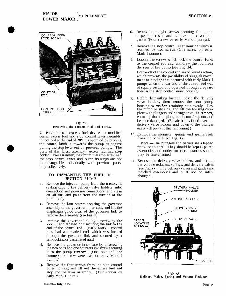
Fig. 14. Removing the Control Rod and Forks.
7. Push button excess fuel device-a modified design excess fuel and stop control lever assembly, introduced at the end of 1954, is operated by pushing the control knob in towards the pump as against pulling the stop lever out on previous pumps. The parts of this latest assembly-excess fuel and stop control lever assembly, maximum fuel stop screw and the stop control inner and outer housings are not interchangeable individually with previous parts, only collectively.
TO DISMANTLE THE FUEL IN- JECTION PUMP
I. Remove the injection pump from the tractor, fit sealing caps to the delivery valve holders, inlet connection and governor connections, and clean off all dirt and paint from the outside of the pump body.
2. Remove the four screws securing the governor assembly to the governor inner case, and lift the diaphragm guide clear of the governor link to remove the assembly (see Fig. 8).
3. Remove the governor link by unscrewing the locknut and tapered bolt securing the link to the end of the control rod. (Early Mark I control rods had a threaded end which was located through the governor link and secured by a self-locking or castellated nut.)
4. Remove the governor inner case by unscrewing the two bolts and one countersunk screw securing it to the pump cambox. (One bolt and one countersunk screw were used on early Mark I pumps.)
5. Remove the four screws from the stop control outer housing and lift out the excess fuel and stop control lever assembly. (Two screws on early Mark I units.)
SECTION 2
6 . Remove the eight screws securing the pump inspection cover and remove the cover and gasket (Four screws on early Mark I pumps).
7. Remove the stop control inner housing which is retained by two screws (One screw on early Mark I pumps).
8. Loosen the screws which lock the control forks to the control rod and withdraw the rod from the rear of the pump (see Fig. 14.) Both ends of the control rod are of round section, which prevents the possibility of sluggish move- ment or binding that occurred with early Mark I pumps when the rear end of the control rod was of square section and operated through a square hole in the stop control inner housing.
g. Before dismantling further, loosen the delivery valve holders, then remove the four pump housing to cambox retaining nuts evenly. Lay the pump on its side, and lift the housing com- plete with plungers and springs from the cambox, ensuring that the plungers do not drop out and become damaged. (Elastic bands fitted over the delivery valve holders and down to the plunger arms will prevent this happening.)
10. Remove the plungers, springs and spring seats from the barrels (see Fig. 23).
Note.-The plungers and barrels are a lapped fit to one another. They should be kept as paired assemblies and under no circumstances should they be interchanged.
I I. Remove the delivery valve holders, and lift out the volume reducers, springs, and delivery valves (see Fig. 15). The delivery valves and guides are matched assemblies and must not be inter- changed.
Y VALVE HOLDER
VOLUME REDUCER
VALVE SPRING
DELIVERY VALVE
LOCATING
Fig. 15. Delivery Valve, Spring and Volume Reducer.
Issued-July, 1959 Page 9
MAJOR POWER MAJOR
)SUPPLEMENT SECTION 2
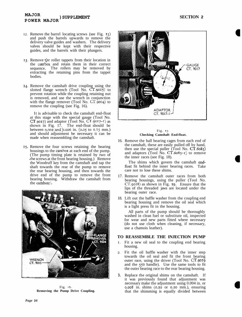
12. Remove the barrel locating screws (see Fig. 15) and push the barrels upwards to remove the delivery valve guides and washers. The delivery valves should be kept with their respective guides, and the barrels with their plungers.
13. Remove i$e roller tappets from their location in the cam5ox and retain them in their correct sequence. The rollers may be removed by extracting the retaining pins from the tappet bodies.
14. Remove the camshaft drive coupling using the slotted flange wrench (Tool No. CT.9015) to prevent rotation while the coupling retaining nut is removed, and use the wrench in conjunction with the flange remover (Tool No. CT.9004) to remove the coupling (see Fig. 16).
I t is advisable to check the camshaft end-float at this stage with the special gauge (Tool No. cT.9017) and adaptor (Tool No. cT.9017-I) as shown in Fig. 17. The end-float should be between o.ooz;and~0.006 in. (0.05 to 0.15 mm.) and should adjustment be necessary it can be made when reassembling the camshaft.
15. Remove the four screws retaining the bearing housings to the cambox at each end of the pump. (The pump timing plate is retained by two of ,the screws at the front bearing housing.) Remove the Woodruff key from the camshaft and tap the shaft towards the rear of the pump to remove the rear bearing housing, and then towards the drive end of the pump to remove the front bearing housing. Withdraw the camshaft from the cambox: l.
Fig. 16. Removing the Pump Drive Coupling.
Fig. 17. Checking Camshaft End-float.
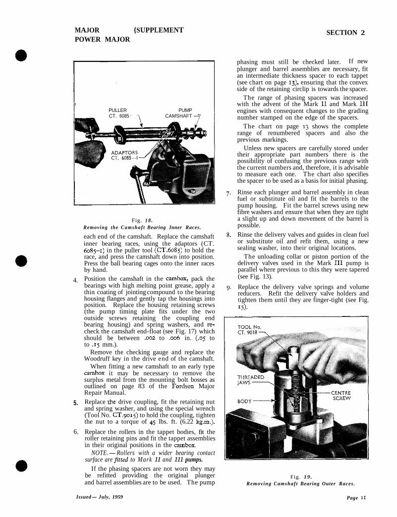
16. Remove the ball bearing cages from each end of the camshaft, these are easily pulled off by hand, then use the special puller (Tool No. CT.6085) and adaptors (Tool No. CT.6085-I) to remove the inner races (see Fig. 18).
The shims which govern the camshaft end- lloat fit behind the inner bearing races. Take care not to lose these shims.
17. Remove the camshaft outer races from both bearing housings, using the puller (Tool No. CT.9018) as shown in Fig. 19. Ensure that the lips of the threaded jaws are located under the bearing outer race.
18. Lift out the baffle washer from the coupling end bearing housing and remove the oil seal which is a light press fit in the housing.
All parts of the pump should be thoroughly washed in clean fuel or substitute oil, inspected for wear and new parts fitted where necessary (do not use cloth when cleaning, if necessary, use a chamois leather).
TO REASSEMBLE THE INJECTION PUMP I. Fit a new oil seal to the coupling end bearing
housing.
2. Fit the oil baffle washer with the inner step towards the oil seal and fit the front bearing outer race, using the driver (Tool No. CT.9019 and the 550 handle). Use the same tools to fit the outer bearing race to the rear bearing housing.
3. Replace the original shims on the camshaft. If it was previously found that adjustment was necessary make the adjustment using 0.004 in. or 0.008 in. shims (0.10 or 0.20 mm.), ensuring that the shimming is equally divided between
Page 10
MAJOR {SUPPLEMENT POWER MAJOR
SECTION 2
PULLER PUMP I CT. 6085 7 CAMSHAFT - I.- / I
Fig. 1 8 . Removing the Camshaf t Bearing Inner Races.
each end of the camshaft. Replace the camshaft inner bearing races, using the adaptors (CT. 6085-1) in the puller tool (CT.6085) to hold the race, and press the camshaft down into position. Press the ball bearing cages onto the inner races by hand.
4. Position the camshaft in the cambox, pack the bearings with high melting point grease, apply a thin coating of jointing compound to the bearing housing flanges and gently tap the housings into position. Replace the housing retaining screws (the pump timing plate fits under the two outside screws retaining the coupling end bearing housing) and spring washers, and re- check the camshaft end-float (see Fig. 17) which should be between .oo2 to .006 in. (.OS to to .15 mm.).
Remove the checking gauge and replace the Woodruff key in the drive end of the camshaft.
When fitting a new camshaft to an early type cambox it may be necessary to remove the surplus metal from the mounting bolt bosses as outlined on page 83 of the Fordson Major Repair Manual.
5. Replace rhe drive coupling, fit the retaining nut and spring washer, and using the special wrench (Tool No. CT.9015) to hold the coupling, tighten the nut to a torque of 45 lbs. ft. (6.22 kg.m.).
6. Replace the rollers in the tappet bodies, fit the roller retaining pins and fit the tappet assemblies in their original positions in the cambox.
NOTE.-Rollers with a wider bearing contact surface are fitted to Mark 11 and 111 pumps.
If the phasing spacers are not worn they may be refitted providing the original plunger and barrel assemblies are to be used. The pump
phasing must still be checked later. If new plunger and barrel assemblies are necessary, fit an intermediate thickness spacer to each tappet (see chart on page 13), ensuring that the convex side of the retaining circlip is towards the spacer.
The range of phasing spacers was increased with the advent of the Mark I1 and Mark I11 engines with consequent changes to the grading number stamped on the edge of the spacers.
The chart on page 13 shows the complete range of renumbered spacers and also the previous markings.
Unless new spacers are carefully stored under their appropriate part numbers there is the possibility of confusing the previous range with the current numbers and, therefore, it is advisable to measure each one. The chart also specifies the spacer to be used as a basis for initial phasing.
Rinse each plunger and barrel assembly in clean fuel or substitute oil and fit the barrels to the pump housing. Fit the barrel screws using new fibre washers and ensure that when they are tight a slight up and down movement of the barrel is possible.
Rinse the delivery valves and guides in clean fuel or substitute oil and refit them, using a new sealing washer, into their original locations.
The unloading collar or piston portion of the delivery valves used in the Mark I11 pump is parallel where previous to this they were tapered (see Fig. 13).
Replace the delivery valve springs and volume reducers. Refit the delivery valve holders and tighten them until they are finger-tight (see Fig.
Fig. 19. Removing Camshaf t Bearing Outer Races.
Issued- July, 1959 Page 11
MAJOR )SUPPLEMENT POWER MAJOR
SECTION 2
10. Rinse the plungers and fit them to their respective barrels. Check that they are perfectly free. At this stage omit fitting the plunger springs and spring seats as it is easier to phase the pump without them.
Fit the pump housing to the cambox and secure in positlon with four nuts and spring washers.
I SPILL PIPE No CT. 90 I
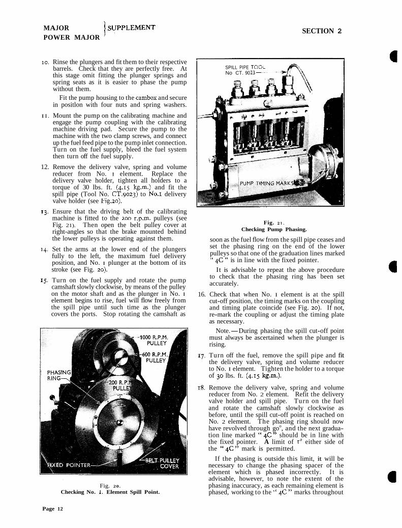
I I . Mount the pump on the calibrating machine and engage the pump coupling with the calibrating machine driving pad. Secure the pump to the machine with the two clamp screws, and connect up the fuel feed pipe to the pump inlet connection. Turn on the fuel supply, bleed the fuel system then turn off the fuel supply.
12. Remove the delivery valve, spring and volume reducer from No. I element. Replace the delivery valve holder, tighten all holders to a torque of 30 lbs. ft. (4.15 kg.m.) and fit the spill pipe (Tool No. CT.9023) to No.1 delivery valve holder (see Fig.20).
13. Ensure that the driving belt of the calibrating machine is fitted to the 200 r.p.m. pulleys (see Fig. 21). Then open the belt pulley cover at right-angles so that the brake mounted behind the lower pulleys is operating against them.
r4. Set the arms at the lower end of the plungers fully to the left, the maximum fuel delivery position, and No. I plunger at the bottom of its stroke (see Fig. 20).
IS. Turn on the fuel supply and rotate the pump camshaft slowly clockwise, by means of the pulley on the motor shaft and as the plunger in No. I element begins to rise, fuel will flow freely from the spill pipe until such time as the plunger covers the ports. Stop rotating the camshaft as
Fig. 20.
Checking No. 1. Element Spill Point.
Fig. IT. Checking Pump Phasing.
soon as the fuel flow from the spill pipe ceases and set the phasing ring on the end of the lower pulleys so that one of the graduation lines marked " qC " is in line with the fixed pointer.
I t is advisable to repeat the above procedure to check that the phasing ring has been set accurately.
16. Check that when No. I element is at the spill cut-off position, the timing marks on the coupling and timing plate coincide (see Fig. 20). If not, re-mark the coupling or adjust the timing plate as necessary.
Note.-During phasing the spill cut-off point must always be ascertained when the plunger is rising.
, Turn off the fuel, remove the spill pipe and fit the delivery valve, spring and volume reducer to No. I element. Tighten the holder to a torque of 30 lbs. ft. (4.15 kgm.).
Remove the delivery valve, spring and volume reducer from No. 2 element. Refit the delivery valve holder and spill pipe. Turn on the fuel and rotate the camshaft slowly clockwise as before, until the spill cut-off point is reached on No. 2 element. The phasing ring should now have revolved through goo, and the next gradua- tion line marked " qC " should be in line with the fixed pointer. A limit of I" either side of the " qC " mark is permitted.
If the phasing is outside this limit, it will be necessary to change the phasing spacer of the element which is phased incorrectly. I t is advisable, however, to note the extent of the phasing inaccuracy, as each remaining element is phased, working to the " qC " marks throughout
Page 12
MAJOR POWER MAJOR
)SUPPLEMENT
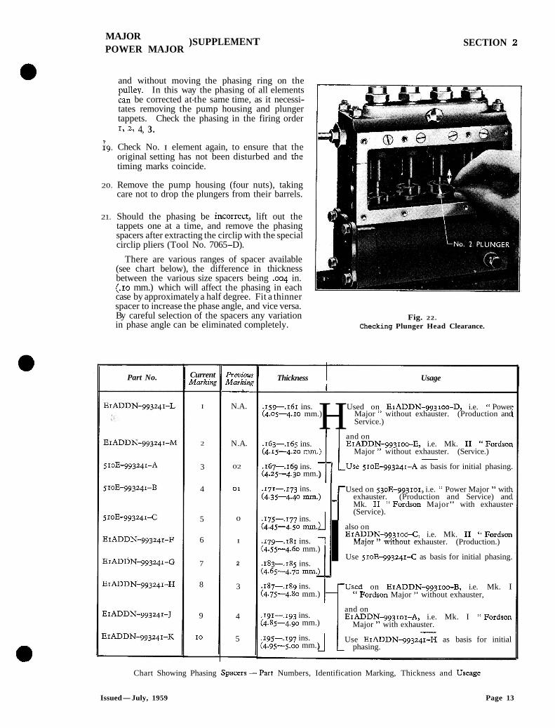
and without moving the phasing ring on the pulley. In this way the phasing of all elements can be corrected at-the same time, as it necessi- tates removing the pump housing and plunger tappets. Check the phasing in the firing order 1, 2, 4, 3.
ig. Check No. I element again, to ensure that the original setting has not been disturbed and the timing marks coincide.
20. Remove the pump housing (four nuts), taking care not to drop the plungers from their barrels.
21. Should the phasing be incorrect, lift out the tappets one at a time, and remove the phasing spacers after extracting the circlip with the special circlip pliers (Tool No. 7065-D).
There are various ranges of spacer available (see chart below), the difference in thickness between the various size spacers being .004 in. (.IO mm.) which will affect the phasing in each case by approximately a half degree. Fit a thinner spacer to increase the phase angle, and vice versa. By careful selection of the spacers any variation in phase angle can be eliminated completely.
Part No. Current Markink
I
2
3
4
5
6
7
8
9
I0
Previou~ Markink -
N.A.
N. A.
02
01
0
I
2
3
4
5
SECTION 2
Fig. 22.
Checking Plunger Head Clearance.
Thickness 1 Usage
.159--.I~I ins. H Used on Er ADDN-gg3 100-D, i.e. " Power (4.05-4.10 mm.) Major " without exhauster. (Production and
Service.)
l 1 and on .163-.165 ins. EIADDN-993100-E, i.e. Mk. I1 "Fordson (4.15-4.20 111111.) Major " without exhauster. (Service.)
.16,-.169 ins. Tl L U s e 51oE-993241-A as basis for initial phasing. (4.25-4.30 mm.)
.I~I-.173 ins. (4.35-4.40 mm.)
.175--.177 ins. (4.45-4.50 mm.) _I .179-,181 ins. 7 (4.55-4.60 mm.) l .183-.185 ins. :4.65--4.70 mm.2_ I
Used on 53oE-993101, i.e. " Power Major " with exhauster. (Production and Service) and Mk. I1 " Fordson Major" with exhauster (Service).
l also on EIADDN-993100-C, i.e. Mk. I1 " Fordson
Major without exhauster. (Production.)
Use 51oE-993241-C as basis for initial phasing.
,187-.18g ins. h U;yd on EIADDN-993100-B, i.e. Mk. I :4.75-4.80 mm.) Fordson Major " without exhauster,
,191-,193 ins. :4.85-4.90 mm.)
I95-.197 ins. 14.95-5.00 mm.) J
and on EIADDN-993101-A, i.e. Mk. I " Fordson
Major " with exhauster.
Use EIADDN-993241-H as basis for initial phasing.
Chart Showing Phasing Spacers -Part Numbers, Identification Marking, Thickness and Useage
Issued-July, 1959 Page 13
MAJOR POWER MAJOR
) SUPPLEMENT SECTION 2
22. Refit the pump housing to the cambox, again omitting the plunger springs, and check that plunger head clearance exists on each element with the plunger at the top of its stroke (see Fig. 22).
If there is no clearance on one element, replacelthe tappet spacer of this element with a thinner spacer, and re-phase the other elements to this one. Ensure that the timing marks on the pump coupling and timing plate coincide when No. I element is set on spill cut-off point.
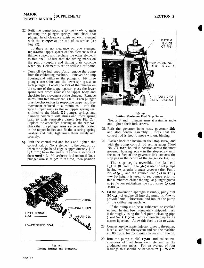
23. Turn off the fuel supply'and remove the pump from the calibrating machine. Remove the pump housing and withdraw the plungers. Fit three plunger arm shims and the lower spring seat to each plunger. Locate the faot of the plunger on the centre of the tappet spacer, press the lower spring seat down against the tappet body and check for free movement of the plunger. Remove shims until free movement is felt. Each plunger must be checked on its respective tappet and free movement reduced to a minimum. Refit the spring upper seats (a thicker upper spring seat is fitted to the Mark I11 pump), springs and plungers complete with shims and lower spring seats to their respective barrels (see Fig. 23). Replace the assembled housing on the cambox, check that the plunger arms are correctly located in the tappet bodies and fit the securing spring washers and nuts, tightening them evenly and securely.
24. Refit the control rod and forks and tighten the control fork of No. I element to the control rod when the right-hand edge is approximately in. (3.2 mm.) from the end of the square section of the controk rod. Move the control rod until No. I plunger arm is at go0 to the rod, then position
LOWER SPRING SEAT 1
Fig. 23. Fitting Springs and Plungers.
Fig. 24. Setting Maximum Fuel Stop Screw.
Nos. 2, 3, and 4 plunger arms at a similar angle and tighten their fork screws.
25. Refit the governor inner case, governor link, and stop control assembly. Check that the control rod is free to move without binding.
26. Slacken back the maximum fuel stop screw, and with the pump control rod setting gauge (Tool No. CT.9021) bolted in position across the inner governor housing, screw in the stop screw until the outer face of the governor link contacts the stop peg in the centre of the gauge (see Fig. 24).
The stop peg is reversible, the plain end (.33 in. (8.5 mm.) in heighc) is used to set pumps having 50" angular plunger grooves (after Pump No. 61994)~ and the knurled end (.41 in. (10.5 mm.)in height) is used to set pumps prior to this number which had the angular plunger groove at 45". When set, tighten the stop screw locknut securely.
27. Fit the governor diaphragm assembly, put + pint (95 c.cs.) of engine oil into the pump cambox to provide initial lubrication, and mount the pump on the calibrating machine.
If the pump is to be re-calibrated or checked without having been completely stripped, flush it thoroughly using the fuel pump cleaning pipe (Tool No. CT.9001) before connecting up to the master injectors. Allow this fuel to run to waste.
28. Connect up the master injector pipes to the pump, bleed all air from the system and run the machine at 600 r.p.m. for 10 mi~utes to warm up the oil.
29. Run the pump at 600 r.p.m. and collect 200 injections of fuel from each element in the graduated test tubes. For an average of four readings this should be between 11.4-12 C.CS.
Page 14
MAJOR ) SUPPLEMENT POWER MAJOR
SECTION 2
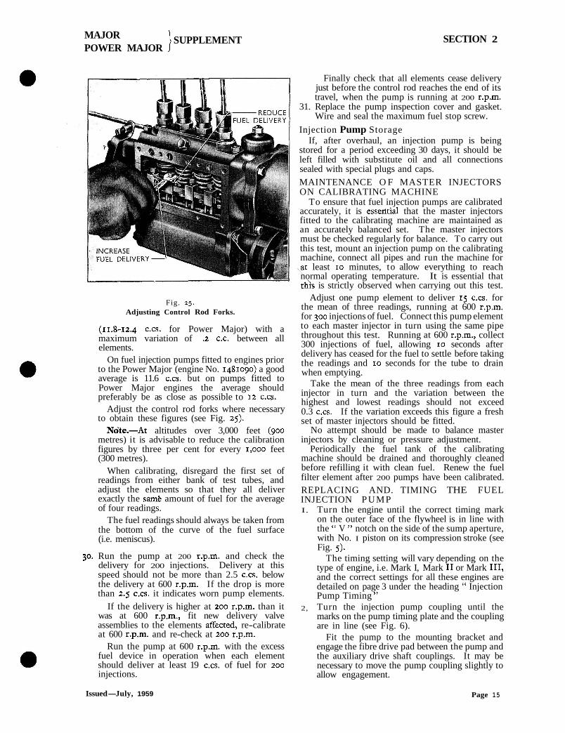
Fig. 25. Adjusting Control Rod Forks.
(11.8-12.4 c.cs. for Power Major) with a maximum variation of .t C.C. between all elements.
On fuel injection pumps fitted to engines prior to the Power Major (engine No. 1481090) a good average is 11.6 c.cs. but on pumps fitted to Power Major engines the average should preferably be as close as possible to 12 c . c~ ,
Adjust the control rod forks where necessary to obtain these figures (see Fig. 25).
No'te.-At altitudes over 3,000 feet (900 metres) it is advisable to reduce the calibration figures by three per cent for every ~ ,ooo feet (300 metres).
When calibrating, disregard the first set of readings from either bank of test tubes, and adjust the elements so that they all deliver exactly the samk amount of fuel for the average of four readings.
The fuel readings should always be taken from the bottom of the curve of the fuel surface (i.e. meniscus).
30. Run the pump at 200 r.p.m. and check the delivery for 200 injections. Delivery at this speed should not be more than 2.5 c.cs. below the delivery at 600 r.p.m. If the drop is more than 2.5 c.cs. it indicates worn pump elements.
If the delivery is higher at 200 r.p.m. than it was at 600 r.p.m., fit new delivery valve assemblies to the elements affected, re-calibrate at 600 r.p.m. and re-check at 200 r.p.m.
Run the pump at 600 r.p.m. with the excess fuel device in operation when each element should deliver at least 19 cm. of fuel for 200 injections.
Finally check that all elements cease delivery just before the control rod reaches the end of its travel, when the pump is running at 200 r.p.m.
31. Replace the pump inspection cover and gasket. Wire and seal the maximum fuel stop screw.
Injection Pump Storage If, after overhaul, an injection pump is being
stored for a period exceeding 30 days, it should be left filled with substitute oil and all connections sealed with special plugs and caps.
MAINTENANCE O F MASTER INJECTORS ON CALIBRATING MACHINE
To ensure that fuel injection pumps are calibrated accurately, it is esseatial that the master injectors fitted to the calibrating machine are maintained as an accurately balanced set. The master injectors must be checked regularly for balance. To carry out this test, mount an injection pump on the calibrating machine, connect all pipes and run the machine for
\at least 10 minutes, to allow everything to reach normal operating temperature. It is essential that thh is strictly observed when carrying out this test.
Adjust one pump element to deliver 15 c.cs. for the mean of three readings, running at 600 r.p.m. for 300 injections of fuel. Connect this pump element to each master injector in turn using the same pipe throughout this test. Running at 600 r.p.m., collect 300 injections of fuel, allowing 10 seconds after delivery has ceased for the fuel to settle before taking the readings and 10 seconds for the tube to drain when emptying.
Take the mean of the three readings from each injector in turn and the variation between the highest and lowest readings should not exceed 0.3 c.cs. If the variation exceeds this figure a fresh set of master injectors should be fitted.
No attempt should be made to balance master injectors by cleaning or pressure adjustment.
Periodically the fuel tank of the calibrating machine should be drained and thoroughly cleaned before refilling it with clean fuel. Renew the fuel filter element after 200 pumps have been calibrated. REPLACING AND. TIMING THE FUEL INJECTION PUMP I. Turn the engine until the correct timing mark
on the outer face of the flywheel is in line with the " V " notch on the side of the sump aperture, with No. I piston on its compression stroke (see Fig. 5).
The timing setting will vary depending on the type of engine, i.e. Mark I, Mark I1 or Mark 111, and the correct settings for all these engines are detailed on page 3 under the heading " Injection Pump Timing "
2, Turn the injection pump coupling until the marks on the pump timing plate and the coupling are in line (see Fig. 6).
Fit the pump to the mounting bracket and engage the fibre drive pad between the pump and the auxiliary drive shaft couplings. It may be necessary to move the pump coupling slightly to allow engagement.
Issued- July, 1959 Page 15
MAJOR POWER MAJOR
1 SUPPLEMENT SECTION 2
3. Before tightening the pump mounting bolts fit the fuel inlet pipe, governor control pipes and injector high pressure pipes. The injector pipes used on the Mark I1 and I11 engines are of equal length and are looped and clipped in pairs, and from approximately engine No. 1458430 the width across the flats of the pipe nuts'was decreased from 2 in. (19.05 mm.) to 8 in. (15.88 mm.).
4, Tighten the injection pump to mounting bracket screws ensuring that there is a 0.010 in. (0.254 mm.) clearance between the fibre disc and the pump coupling.
Check the pump timing marks, coincide loosen the two claw auxiliary drive shaft coupling, coupling to bring the marks in the claw bolts securely.
if they do not bolts on the and turn the line. Tighten
(reconditioned injectors-blue paint mark) and the nozzle numSer N L I ~ I stamped on the larger diameter shank of the nozzle, the Mark I and I11
4 injectors have green paint spots (yellow for recon- ditioned) and the inscription N L I ~ .
The injectors should be kept to their respective type of engine as specified, although in an emergency they may be interchanged providing that when they are used in engines for which they are not strictly specified, they are used in sets of four.
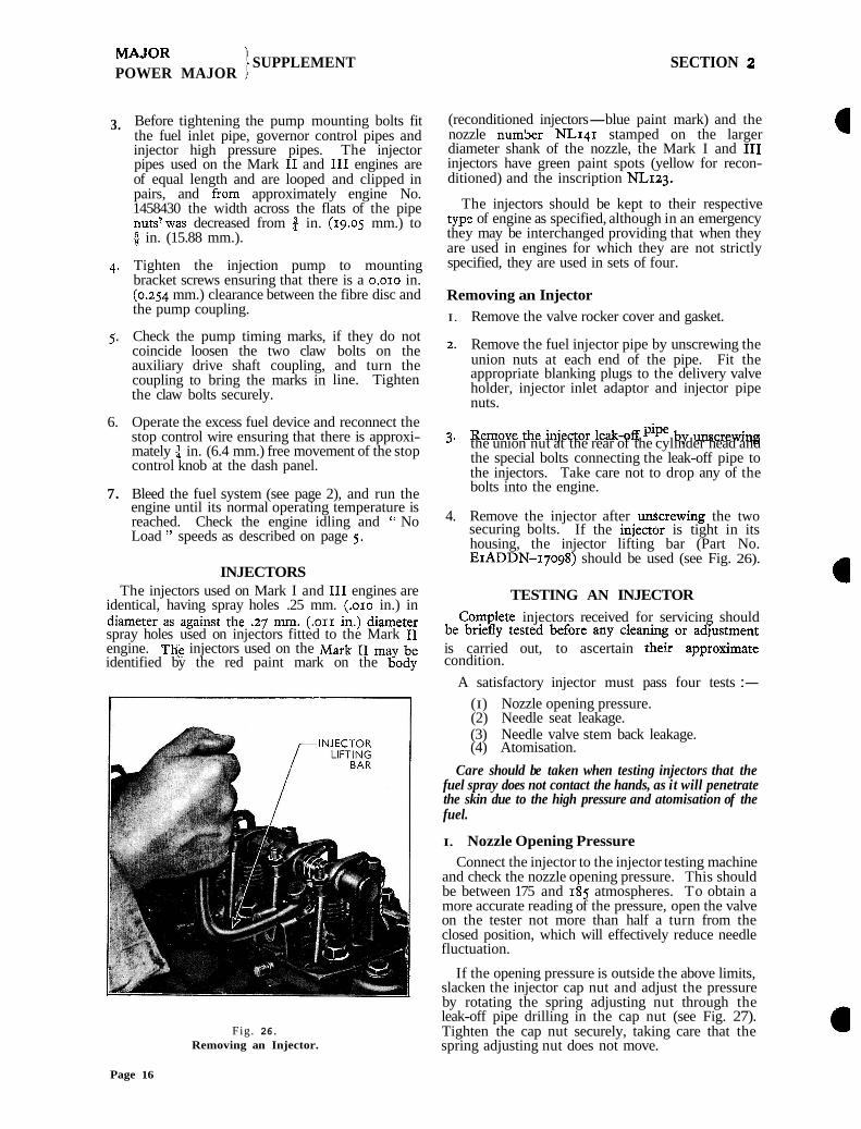
Removing an Injector I. Remove the valve rocker cover and gasket.
Remove the fuel injector pipe by unscrewing the union nuts at each end of the pipe. Fit the appropriate blanking plugs to the delivery valve holder, injector inlet adaptor and injector pipe nuts.
6. Operate the excess fuel device and reconnect the 3. Remove the injector leak-off by unscre-g stop control wire ensuring that there is approxi- mately in. (6.4 mm.) free movement of the stop the union nut at the rear of the cylinder head and
control knob at the dash panel. the special bolts connecting the leak-off pipe to the injectors. Take care not to drop any of the
7. Bleed the fuel system (see page 2), and run the bolts into the engine. engine until its normal operating temperature is reached. Check the engine idling and " No 4. Remove the injector after unScrewing the two Load " speeds as described on page 5. securing bolts. If the inject& is tight in its
housing, the injector lifting bar (Part No. EIADDN-17098) should be used (see Fig. 26).
INJECTORS The injectors used on Mark I and I11 engines are TESTING AN INJECTOR
identical, having spray holes .25 mm. (.OIO in.) in diameter as against the .27 mm. (.or1 in.) diameter Complete injectors received for servicing should spray holes used on injectors fitted to the Mark I1 be briefly tested before any cleaning or adiustment engine. T& injectors used on the Mark 11 may be is carried out, to ascertain thdir approxi~nate identified by the red paint mark on the body condition.
A satisfactory injector must pass four tests :-
(I) Nozzle opening pressure. (2) Needle seat leakage. (3) Needle valve stem back leakage. (4) Atomisation.
Care should be taken when testing injectors that the fuel spray does not contact the hands, as it will penetrate the skin due to the high pressure and atomisation of the fuel.
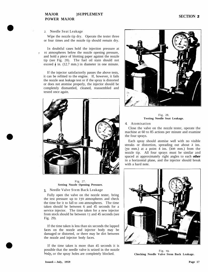
I. Nozzle Opening Pressure Connect the injector to the injector testing machine
and check the nozzle opening pressure. This should be between 175 and 185 atmospheres. To obtain a more accurate reading of the pressure, open the valve on the tester not more than half a turn from the closed position, which will effectively reduce needle fluctuation.
If the opening pressure is outside the above limits, slacken the injector cap nut and adjust the pressure by rotating the spring adjusting nut through the leak-off pipe drilling in the cap nut (see Fig. 27).
Fig. 26. Tighten the cap nut securely, taking care that the Removing an Injector. spring adjusting nut does not move.
Page 16
MAJOR )SUPPLEMENT POWER MAJOR
SECTION 2
2. Needle Seat Leakage
Wipe the nozzle tip dry. Operate the tester three or four times and the nozzle tip should remain dry.
In doubtful cases hold the injection pressure at 10 atmospheres below the nozzle opening pressure, and hold a piece of blotting paper against the nozzle tip (see Fig. 28). The fuel oil stain should not exceed 8 in. (12.7 mm.) in diameter in one minute.
If the injector satisfactorily passes the above tests, it can be refitted to the engine. If, however, it fails the nozzle seat leakage test or if the spray is distorted or does not atomise properly, the injector should be completely dismantled, cleaned, reassembled and tested once again.
Fig. 27. Setting Nozzle Opening Pressure.
3. Needle Valve S tem Back Leakage
Fully open the valve on the nozzle tester, bring the test pressure up to 150 atmospheres and check the time for it to fall to IOO atmospheres. The time taken should be between 6 and 45 seconds for a service injector. The time taken for a new injector from stock should be between 15 and 45 seconds (see Fig. 29).
If the time taken is less than six seconds the lapped faces on the nozzle and injector body may be damaged or distorted, or there may be dirt between the nozzle and injector body faces.
If the time taken is more than 45 seconds it is
Fig. 28. Testing Needle Seat Leakage.
4. Atomisation Close the valve on the nozzle tester, operate the
machine at 60 to 85 actions per minute and examine the four sprays.
Each spray should atomise well with no visible streaks or distortion, spreading out about 2 ins. (50 mm.) at a point 4 ins. (100 mm.) from the nozzle tip. All four sprays must be similar and spaced at approximately right angles to each other in a horizontal plane, and the injector should break with a hard note.
I
possible that the needle valve is seized in the nozzle Fig. 29. body, or the spray holes are completely blocked. Checking Needle Valve Stem Back Leakage.
Issued-July, 1959 Page 17
MAJOR 'I i SUPPLEMENT POWER MAJOR I
SECTION 2
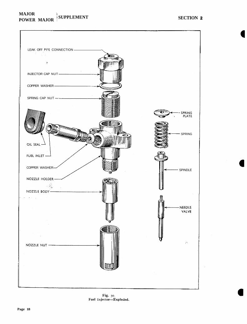
LEAK OFF PIPE CONNECTION X
INJECTOR CAP NUT
COPPER WASHER
SPRING CAP NUT
COPPER WASHER
SPRING
SPINDLE
Fig. 30. Fuel In jector-Exploded.
Page 18
MAJOR POWER MAJOR
] SUPPLEMENT SECTION 2
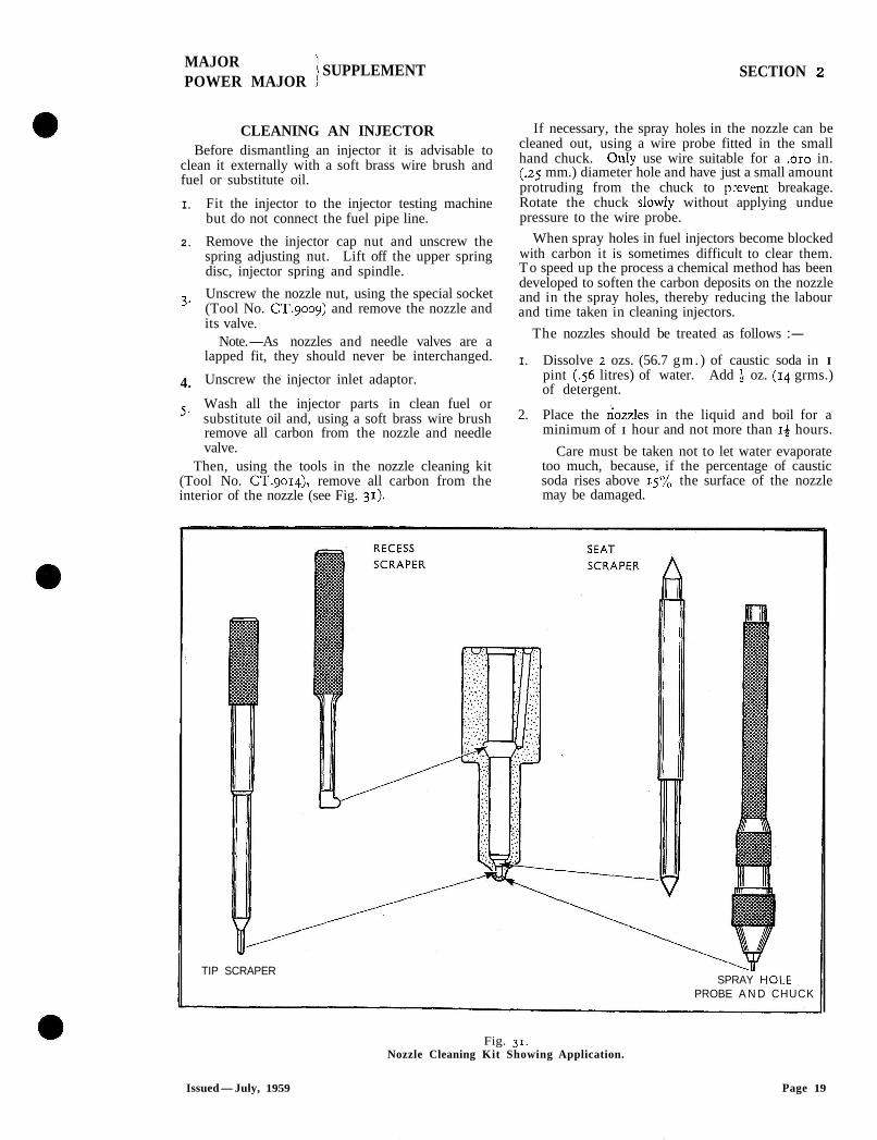
CLEANING AN INJECTOR Before dismantling an injector it is advisable to
clean it externally with a soft brass wire brush and fuel or substitute oil.
I. Fit the injector to the injector testing machine but do not connect the fuel pipe line.
2. Remove the injector cap nut and unscrew the spring adjusting nut. Lift off the upper spring disc, injector spring and spindle.
3. Unscrew the nozzle nut, using the special socket (Tool No. cT.9009) and remove the nozzle and its valve.
Note.-As nozzles and needle valves are a lapped fit, they should never be interchanged.
4. Unscrew the injector inlet adaptor.
5. Wash all the injector parts in clean fuel or substitute oil and, using a soft brass wire brush remove all carbon from the nozzle and needle valve.
Then, using the tools in the nozzle cleaning kit (Tool No. CT.go~q), remove all carbon from the interior of the nozzle (see Fig. 31).
If necessary, the spray holes in the nozzle can be cleaned out, using a wire probe fitted in the small hand chuck. Only use wire suitable for a ,010 in. (.25 mm.) diameter hole and have just a small amount protruding from the chuck to p:event breakage. Rotate the chuck slowly without applying undue pressure to the wire probe.
When spray holes in fuel injectors become blocked with carbon it is sometimes difficult to clear them. To speed up the process a chemical method has been developed to soften the carbon deposits on the nozzle and in the spray holes, thereby reducing the labour and time taken in cleaning injectors.
The nozzles should be treated as follows :-
I. Dissolve 2 ozs. (56.7 g m . ) of caustic soda in I pint (.56 litres) of water. Add 4 oz. (14 grms.) of detergent.
2. Place the hozz~es in the liquid and boil for a minimum of I hour and not more than 14 hours.
Care must be taken not to let water evaporate too much, because, if the percentage of caustic soda rises above 15% the surface of the nozzle may be damaged.
TIP SCRAPER \hi' SPRAY H(
PROBE A N D CHUCK
Fig. 31. Nozzle Cleaning Kit Showing Application.
Issued-July, 1959 Page 19
MAJOR POWER MAJOR
] SUPPLEMENT SECTION 2
Remove the nozzles, wash in running water, and then immerse in de-watering oil. Remove surplus oil by draining.
It will be found that the carbon can easily be removed with a wire brush and a standard pricker wire, or in some cases blown clean with compressed air.
Alternatively, when a hard carbon deposit is formed in the spray holes, it may be softened by immersing the nozzle in "Acetone " for a short period. Up to half an hour is normally sufficient.
Warning.-"Acetone " is a highly inflammable liquid and must not be brought near a naked flame.
It is important that immediately the nozzle is removed from the fluid, it must be rinsed in clean fuel or substitute fuel oil to prevent corrosion on the highly finished surfaces.
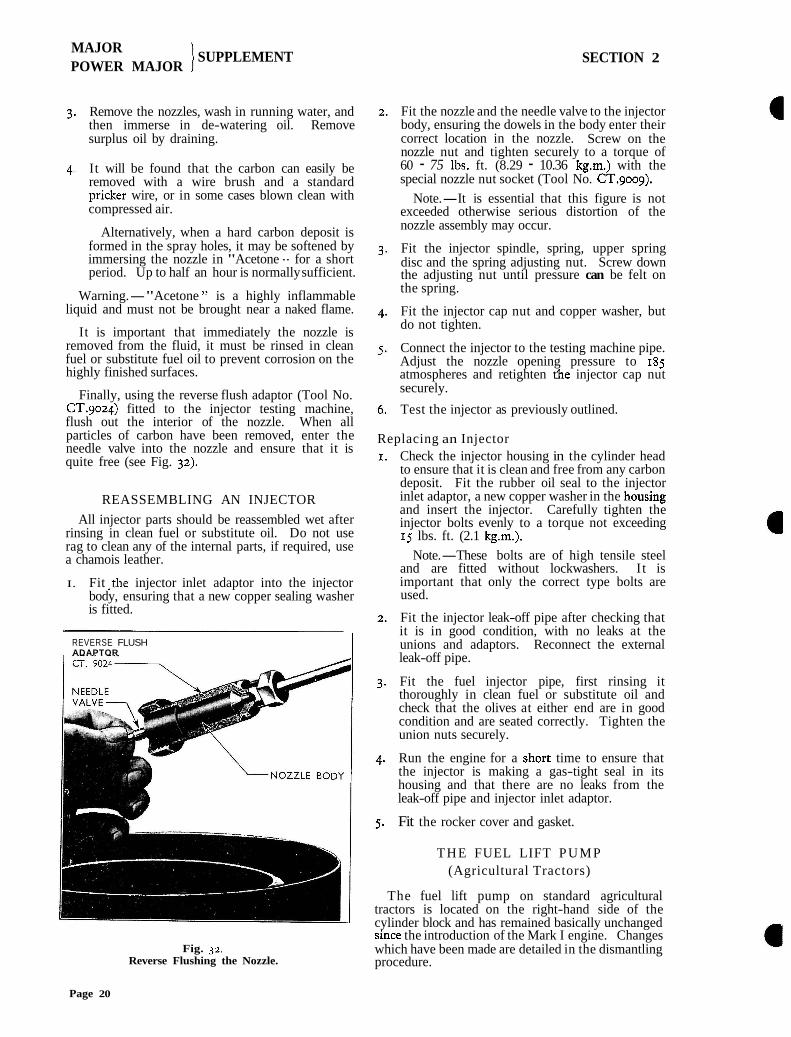
Finally, using the reverse flush adaptor (Tool No. CT.9024) fitted to the injector testing machine, flush out the interior of the nozzle. When all particles of carbon have been removed, enter the needle valve into the nozzle and ensure that it is quite free (see Fig. 32).
REASSEMBLING AN INJECTOR
All injector parts should be reassembled wet after rinsing in clean fuel or substitute oil. Do not use rag to clean any of the internal parts, if required, use a chamois leather.
I. Fit .the injector inlet adaptor into the injector body, ensuring that a new copper sealing washer is fitted.
REVERSE FLUSH ADAPTOR 1
Fig. 32. Reverse Flushing the Nozzle.
Fit the nozzle and the needle valve to the injector body, ensuring the dowels in the body enter their correct location in the nozzle. Screw on the nozzle nut and tighten securely to a torque of 60 - 75 Ibs. ft. (8.29 - 10.36 kg.m.) with the special nozzle nut socket (Tool No. CT.goog).
Note.-It is essential that this figure is not exceeded otherwise serious distortion of the nozzle assembly may occur.
Fit the injector spindle, spring, upper spring disc and the spring adjusting nut. Screw down the adjusting nut until pressure can be felt on the spring.
Fit the injector cap nut and copper washer, but do not tighten.
Connect the injector to the testing machine pipe. Adjust the nozzle opening pressure to 185 atmospheres and retighten rhe injector cap nut securely.
Test the injector as previously outlined.
Replacing an Injector Check the injector housing in the cylinder head to ensure that it is clean and free from any carbon deposit. Fit the rubber oil seal to the injector inlet adaptor, a new copper washer in the housing and insert the injector. Carefully tighten the injector bolts evenly to a torque not exceeding 15 lbs. ft. (2.1 kg.m.).
Note.-These bolts are of high tensile steel and are fitted without lockwashers. I t is important that only the correct type bolts are used.
Fit the injector leak-off pipe after checking that it is in good condition, with no leaks at the unions and adaptors. Reconnect the external leak-off pipe.
Fit the fuel injector pipe, first rinsing it thoroughly in clean fuel or substitute oil and check that the olives at either end are in good condition and are seated correctly. Tighten the union nuts securely.
Run the engine for a s.hort time to ensure that the injector is making a gas-tight seal in its housing and that there are no leaks from the leak-off pipe and injector inlet adaptor.
Fit the rocker cover and gasket.
THE FUEL LIFT PUMP (Agricultural Tractors)
The fuel lift pump on standard agricultural tractors is located on the right-hand side of the cylinder block and has remained basically unchanged since the introduction of the Mark I engine. Changes which have been made are detailed in the dismantling procedure.
Page 20
MAJOR POWER MAJOR
/ SUPPLEMENT SECTION 2
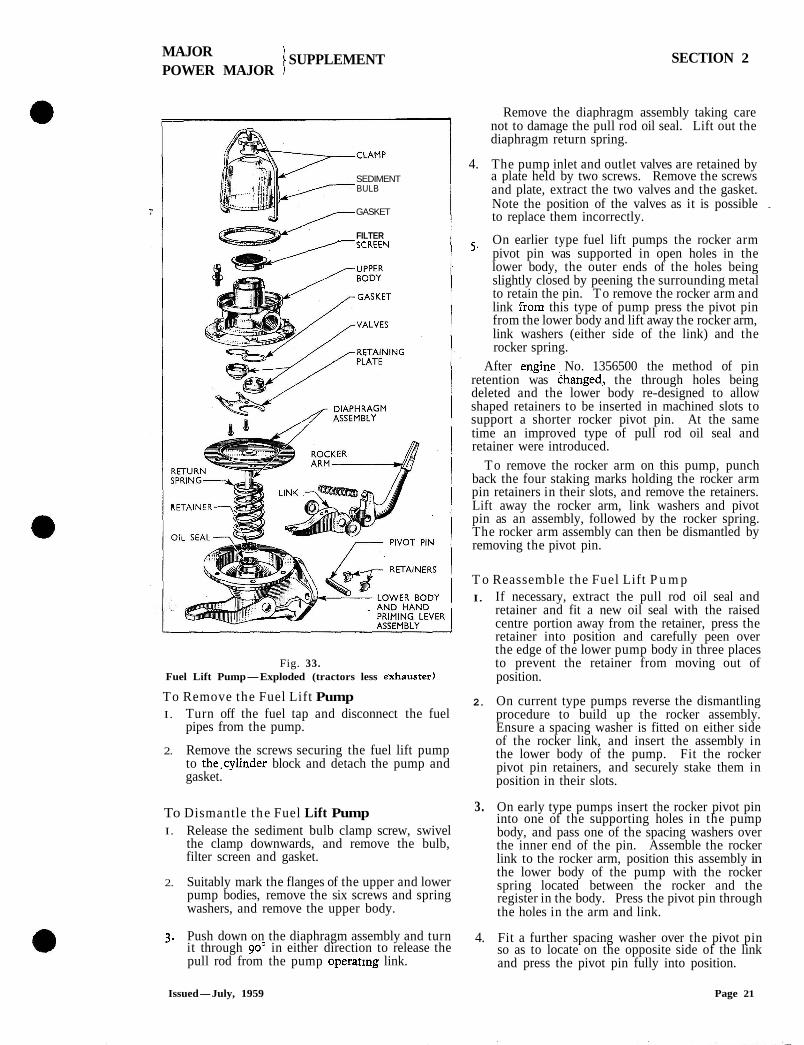
SEDIMENT BULB
GASKET
FILTER /SCREEN
Fig. 33. Fuel Lift Pump-Exploded (tractors less exhauster)
To Remove the Fuel Lift Pump I. Turn off the fuel tap and disconnect the fuel
pipes from the pump.
2. Remove the screws securing the fuel lift pump to the,cylinder block and detach the pump and gasket.
To Dismantle the Fuel Lift Pump I. Release the sediment bulb clamp screw, swivel
the clamp downwards, and remove the bulb, filter screen and gasket.
2. Suitably mark the flanges of the upper and lower pump bodies, remove the six screws and spring washers, and remove the upper body.
3. Push down on the diaphragm assembly and turn it through goo in either direction to release the pull rod from the pump operatmg link.
Remove the diaphragm assembly taking care not to damage the pull rod oil seal. Lift out the diaphragm return spring.
4. The pump inlet and outlet valves are retained by a plate held by two screws. Remove the screws and plate, extract the two valves and the gasket. Note the position of the valves as it is possible . to replace them incorrectly.
5 . On earlier type fuel lift pumps the rocker arm pivot pin was supported in open holes in the lower body, the outer ends of the holes being slightly closed by peening the surrounding metal to retain the pin. To remove the rocker arm and link from this type of pump press the pivot pin from the lower body and lift away the rocker arm, link washers (either side of the link) and the rocker spring.
After engine> No. 1356500 the method of pin retention was Changed, the through holes being deleted and the lower body re-designed to allow shaped retainers to be inserted in machined slots to support a shorter rocker pivot pin. At the same time an improved type of pull rod oil seal and retainer were introduced.
To remove the rocker arm on this pump, punch back the four staking marks holding the rocker arm pin retainers in their slots, and remove the retainers. Lift away the rocker arm, link washers and pivot pin as an assembly, followed by the rocker spring. The rocker arm assembly can then be dismantled by removing the pivot pin.
T o Reassemble the Fuel Lift P u m p I . If necessary, extract the pull rod oil seal and
retainer and fit a new oil seal with the raised centre portion away from the retainer, press the retainer into position and carefully peen over the edge of the lower pump body in three places to prevent the retainer from moving out of position.
2. On current type pumps reverse the dismantling procedure to build up the rocker assembly. Ensure a spacing washer is fitted on either side of the rocker link, and insert the assembly in the lower body of the pump. Fit the rocker pivot pin retainers, and securely stake them in position in their slots.
3. On early type pumps insert the rocker pivot pin into one of the supporting holes in the pump body, and pass one of the spacing washers over the inner end of the pin. Assemble the rocker link to the rocker arm, position this assembly in the lower body of the pump with the rocker spring located between the rocker and the register in the body. Press the pivot pin through the holes in the arm and link.
4. Fit a further spacing washer over the pivot pin so as to locate on the opposite side of the link and press the pivot pin fully into position.
Issued-July, 1959 Page 21
MAJOR ' SUPPLEMENT POWER MAJOR 1 SECTION 2
Check that the rocker arm and hand priming lever work freely and correctly, and then peen over the metal adjacent to the outer ends of the rocker arm pin to retain it in position.
Locate the diaphragm return spring in position in the lower body. Enter the diaphragm pull rod carefully through the oil seal, locate the rod in the slot of the rocker arm link and rotate the diaphragm assembly through go0 to retain it in position.
This operation will be simplified by holding the rocker arm firmly outwards.
Install the valve gasket in the upper pump body and fit a valve assembly into the inlet port, with the three ports of the cage towards the diaphragm. Fit the other valve assembly in the outlet port with the three ports of the cage towards the top of the pump, Install the valve retainer, each pair of lugs locating the valve assemblies, and secure with the two screws.
Press the rocker arm fully inwards. Line up the holes in the diaphragm with the holes in the lower body, fit the upper body with the marks previously made on the flanges in line, and replace the six retaining screws and spring washers. Before fully tightening the screws work the rocker arm for several complete strokes to free off the diaphragm.
Refit the filter screen and new gasket. Position the glass filter bulb and retaining clamp on the pump and tighten the clamp screw securely.
T o Replace the P u m p on the Tractor Clean off the and cylinder block mounting faces and turn the engine over until the back of the eccentric on the camshaft is opposite the fuel lift pump mounting face.
Fit the fuel pump into its location, using a new gasket and secure with the two retaining screws and spring washers.
Reconnect the fuel inlet and outlet pipes.
Bleed the fuel system as detailed on page 2.
FUEL LIFT P U M P (Industrial Tractors)
On industrial tractors fitted with exhausters the fuel lift pump is mounted on the fuel injection pump cambox and operated through a spring-loaded arm from an eccentric on the injection pump camshaft.
The lift pump differs from that fitted to standard agricultural tractors and when servicing the pump the following repair procedure should be adopted :-
To Remove the Fuel Lift P u m p I. Turn off the fuel tap and disconnect the fuel
pipes from the lift pump.
Unscrew and remove the two nuts and spring washers securing the fuel lift pump to the injection pump and detach the fuel pump, canting it slightly to allow the operating lever to clear the eccentric and the slotted hole in the injection pump cambox.
To Dismantle the Fuel Lift P u m p
Unscrew the filter cover bolt and remove the cover and filter screen.
Remove the five screws and spring washers securing the upper and lower fuel pump bodies, taking care when separating the flange joint to avoid damaging the diaphragm.
Turn the diaphragm through approximately a quarter of a turn (in either direction) to free the diaphragm rod from the operating lever, and detach the diaphragm.
The diaphragm and pull rod are riveted together and should not be dismantled. Remove the diaphragm spring, oil seal retaining washer and rubber oil seal.
(a) Prior to April 1956 : The inlet and outlet valves are retained by a
plate held in position by three screws. Remove the three screws and lift the plate and gasket, then each valve, together with its spring, and the inlet valve retainer, may be detached from the upper body (see Fig. 35).
(b) After April 1956 : The inlet and outlet valve assemblies are
retained by a spring steel plate secured by two screws. Remove the screws and plate, and lift the two valves assemblies, together with the gasket from the upper body (see Fig. 35).
Should it be necessary to dismantle the lower body, remove the circlip from one end of the pin on which the rocker arm operates and press the pin from the lower pump body. On some pumps, when no circlip is fitted, it may be necessary to relieve the staking on the body before it is possible to remove the pin. The rocker arm, spring, link and two washers can then be removed.
TO Reassemble the Fuel Lift P u m p
If the lower body has been completely dismantled, first replace the rocker arm and link assembly as follows :-
Insert the rocker arm pin through one hole in the lower pump body, so there is sufficient room to position one of the thrust washers in rhe longitudinal aperture adjacent to the pin. -
Fit one thrust washer, insert the link, slotted end first, with the two holes in line with the pin, and the central web uppermost.
Page 22
MAJOR POWER MAJOR
/ SUPPLEMENT SECTION 2
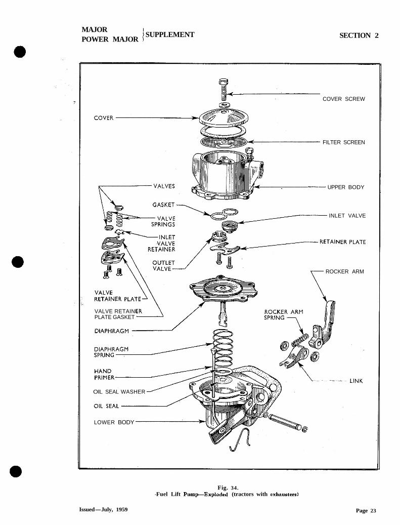
8. COVER SCREW 63s
FILTER SCREEN
UPPER BODY
INLET VALVE
ROCKER ARM
VALVE RETAIN PLATE GASKET
OIL SEAL WASHER
LOWER BODY
Fig. 34. -Fuel Lift PumpExploded (tractors with exhausters)
Issued-July, 1959 Page 23
MAJOR POWER 'MAJOR
1 SUPPLEMENT SECTION 2
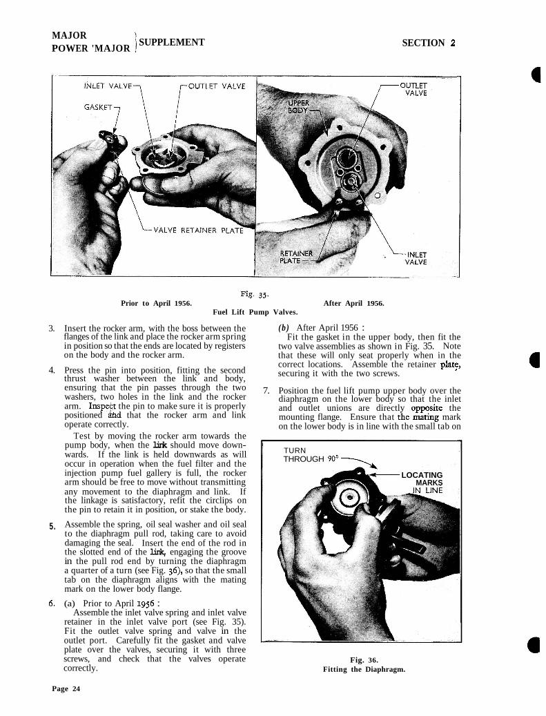
Prior to April 1956. After April 1956. Fuel Lift Pump Valves.
3. Insert the rocker arm, with the boss between the flanges of the link and place the rocker arm spring in position so that the ends are located by registers on the body and the rocker arm.
4. Press the pin into position, fitting the second thrust washer between the link and body, ensuring that the pin passes through the two washers, two holes in the link and the rocker arm. Inspey! the pin to make sure it is properly positioned And that the rocker arm and link operate correctly.
Test by moving the rocker arm towards the pump body, when the link should move down- wards. If the link is held downwards as will occur in operation when the fuel filter and the injection pump fuel gallery is full, the rocker arm should be free to move without transmitting any movement to the diaphragm and link. If the linkage is satisfactory, refit the circlips on the pin to retain it in position, or stake the body.
5. Assemble the spring, oil seal washer and oil seal to the diaphragm pull rod, taking care to avoid damaging the seal. Insert the end of the rod in the slotted end of the link, engaging the groove in the pull rod end by turning the diaphragm a quarter of a turn (see Fig. 36), so that the small tab on the diaphragm aligns with the mating mark on the lower body flange.
6 . (a) Prior to April 1956 : Assemble the inlet valve spring and inlet valve
retainer in the inlet valve port (see Fig. 35). Fit the outlet valve spring and valve in the outlet port. Carefully fit the gasket and valve plate over the valves, securing it with three screws, and check that the valves operate correctly.
(b) After April 1956 : Fit the gasket in the upper body, then fit the
two valve assemblies as shown in Fig. 35. Note that these will only seat properly when in the correct locations. Assemble the retainer plat:, securing it with the two screws.
7. Position the fuel lift pump upper body over the diaphragm on the lower body so that the inlet and outlet unions are directly ouvosite the mounting flange. Ensure that <he mating mark on the lower body is in line with the small tab on
TURN THROUGH 90'-
m- LOCATING MARKS
Fig. 36. Fitting the Diaphragm.
Page 24
MAJOR SUPPLEMENT POWER MAJOR I
SECTIQN 2
the diaphragm. Depress the rocker arm until the diaphragm is level with the flange, fit the five screws with spring washers, locate the priming lever bracket and then tighten the screws finger-tight.
8. Work the rocker arm several complete strokes to centralise the diaphragm and tighten the five screws evenly and securely, with the diaphragm in the down position.
To Replace the Fuel Lift Pump I . Fit the fuel pump into its location using a new
gasket and secure with the two nuts and spring washers.
2. Reconnect the fuel inlet and oudet pipes.
3. Turn on the fuel and bleed the fuel system as detailed on page 2.
FAULT DIAGNOSIS Fault diagnosis on the Diesel Engine can be a
straightforward operation if this is carried out methodically.
To distinguish between a mechanical knock and a fuel knock, run the engine at maximum speed and pull the stop control, if the knock is no longer present it is due to the fuel, if it is still audible, it is due to mechanical reasons. When the fuel supply to the engine is cut off, the mechanical knock will be reduced in volume, but will still be present.
Running faults will be due mainly to faults ar1sir.g in one or more of the following sections. By checking through as outlined, the faulty component or section can be isolated.
Fuel System I. Bleed all air from the fuel system in the
normal manner, if this cannot be eliminated, check back over the pipeline from the lift pump to the fuel tank.
2. Operate the excess fuel device and note that, the control rod moves freely to the excess fuel position.
3. Loosen off the injector pipes at the injector ends, and operate the starter motor, observing approximate equal delivery from each fuel pipe.
4. Pull the stop control with the pipes still disconnected from the injectors and operate the lift pump hand primer. Any flow of fuel indicates a faulty delivery qalve or broken. delivery valve spring.
5. Reconnect the pipes to the injectors and start the engine if possible. As a rough check of injector condition, run the engine just above the idling speed, and loosen the injector pipes one at a time. As each injector is cut out in this way, a definite drop-off in speed should be noticed, if the injector is operating correctly.
Issued-July, 1959
Timing I . Check the fuel injection pump timing by
turning the engine crankshaft until the timing marks are in line as outlined on page 4. At this position, the mark on the fuel injection pump coupling should be in line with the mark on the timing plate on the pump.
2. If any doubt arises as to the accuracy of the timing marks on the pump coupling and timing plate, the fuel injection pump should be spill- timed to the engine. To carry out this operation, set the engine on the firing point for No. I cylinder as outlined in the previous paragraph. Disconnect No. I injector pipe, remove the delivery valve holder and extract the volume reducer, delivery valve and spring. Refit the delivery valve holder to the injection pump body. Fit the spill pipe to the delivery valve holder, slacken the two claw bolts on the engine half of the pump coupling, and fully retard the coupling. Operate the hand primer on the lift pump, and fuel should run from the end of the spill pipe. Slowly advance the injection pump coupling until the 'flow of fuel from the spill pipe just ceases. Tighten the two claw bolts on the pump coupling, the injection pump is now timed correctly to theengine. Refit the delivery valve, spring, volume reducer, and reconnect the ii;jxtion pipe.
Air Supply I. Remove the oil bath of the main air cleaner,
wash out and refill with oil of the correct grade to the correct level if necessary. Ensure that the gauze of the main filter is clean and free from obstructions, and refit the oil bath to the air cleaner.
2. Remove the rubber hose between the main air cleaner and the inlet manifold, check for obstructions and operate the governor control and ensure that the throttle plate travels as far as its stop, giving sufficient opening at the throttle.
3. Check all valve clearances.
4. Check the evenness of the cylinder com- pressions by turning the crankshaft with the starting handle.
Governing I. Check the maximum no-load speed of the
engine. This should be 1,900 r.p.m. If the air system has previously been checked as outlined, and the maximum no-load speed is low, check the governor main spring. The length of the spring should be as outlined in the Specification on page 29.
2. If the air supply has not been previously checked, and the maximum no-load speed is low, it is advisable to carry out the complete check as outlined.
Page 25
MAJOR SUPPLEMENT
POWER MAJOR ) SECTION 2 '
If erratic running at idling speeds is experienced, readjust the damping valve on the governor housing.
If erratic running is experienced under load conditions, check the fuel injection pump control rod for stickiness by pulling the stop control lever sideways to ensure that the control rod will m y e freely to the " excess fuel " position. '
If the engine no-load speed is too high, check for leaks in the system between the inlet manifold and the governor diaphragm. To check the governor diaphragm for leaks, disconnect the vacuum and balance pipes from the governor housing. Pull the stop control
lever to the "stop" position, and seal the two holes in the governor casing, release the stop control lever and there should be no movement on the control rod. If movement of the control rod is observed, it indicates a leaking diaphragm.
- -
6. If excessive black smoke is emitted from the exhaust under load conditions and a l l the foregoing checks have been carried out, screw in the maximum fuel stop on the injection pump until the maximum load is pulled easily, but with only the slightest smoke haze.
The foregoing is intended as a guide for a complete diagnosis of running faults. By carrying out the checks as outlined, faulty components, such as injectors or injection pumps, can be easily and accurately diagnosed.
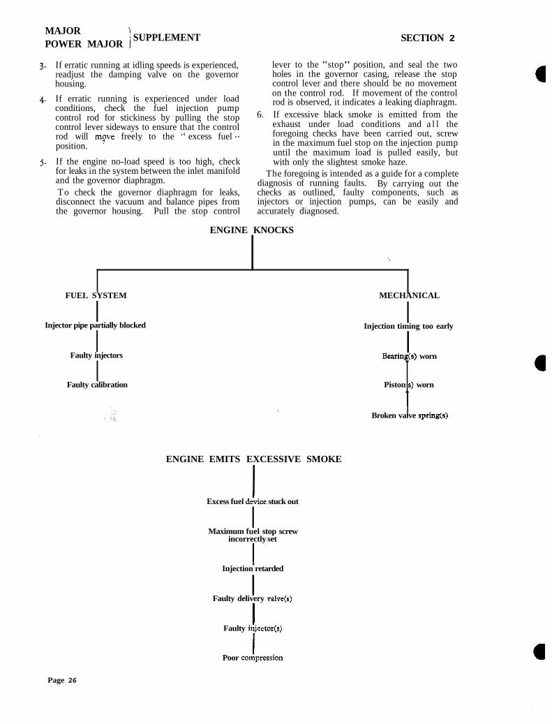
ENGINE KNOCKS
I
FUEL SYSTEM MECHANICAL
I Injector pipe partially blocked
I Injection timing too early
I Faulty injectors
I Bearing(s) worn
I Faulty calibration Piston S) worn I
ENGINE EMITS EXCESSIVE SMOKE
l Broken valve spring(s)
Excess fuel dehce stuck out
I Maximum fuel stop screw
incorrectly set
l I
Injection retarded
I Faulty delivery valve@)
I Faulty &jector(s)
l Poor coGpression
Page 26
MAJOR I
POWER MAJOR 1 SUPPLEMENT SECTION 2
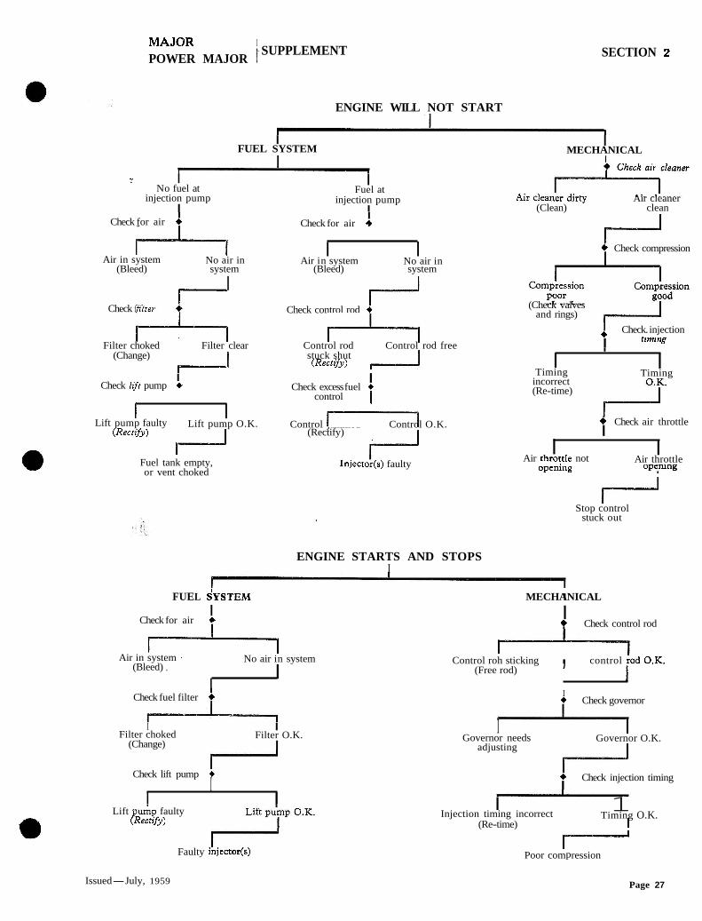
ENGINE WILL NOT START
I FUEL SYSTEM
I MECHANICAL
? I No fuel at
injection pump I
I Fuel at
injection pump I
Check for air & I
+l Check for air *
Air in system No air in I
Air in system I
No air in (Bleed) system (Bleed) system
I I
Check filter
4-7 Check control rod +
+l Filter choked Filter clear Control rod Control rod free (Change) stuck shut
7 I (Rectify) ,-l I
Check lifr pump + I Check excess fuel +
control 1 l I
Lift pump faulty Lift pump O.K. Control jammed I - I Control O.K. (Rectifu) (Rectify)
Fuel tank empty, or vent choked
I Injector(s) faulty
ENGINE STARTS AND STOPS I
I
Air cleaner (Clean) clean
(Check valves and rings)
( Check. injection
I tlming
I I
Timing I
Timing incorrect (Re-time)
4 Check air throttle I
I Air throftle not
I Air throttle
openmg oPe,nW3
Stop control stuck out
FUEL ~ Y S T E M MECHANICAL I
I Check for air 6
I l-----l
Air in system No air in system (Bleed) ,
I I
Check fuel filter
I Filter choked
(Change)
I Filter O.K.
I
I Check lift pump +
I I
I Lift puAp faulty
(Rectzyy)
Faulty ibjector(s)
4 Check compression I
I Check control rod
Control roh sticking , control ih 0.". (Free rod)
I + Check governor I
I Governor needs
1 Governor O.K.
adjusting
4 Check injection timing I
I Injection timing incorrect
1 Timing O.K.
(Re-time) I
Poor compression
Issued-July, 1959 Page 27
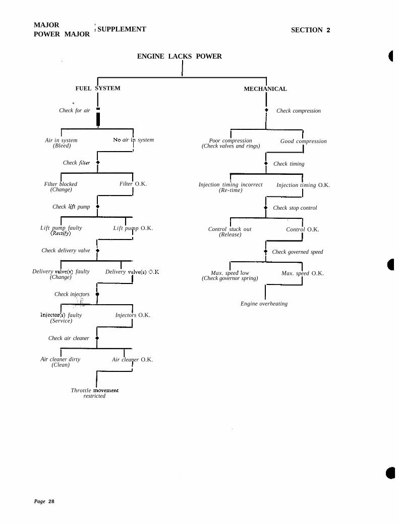
MAJOR POWER MAJOR
FUEL
Check for air
l \ SUPPLEMENT
ENGINE LACKS POWER
I I SYSTEM
l MECHANICAL
I l
SECTION 2
i + Check compression
l Air in system NO air ih system
(Bleed) I
Check Flter i I
I Filter blocked
(Change)
I Filter O.K.
I
Check lift pump 4 I
I Lift pump faulty
I Lift pump O.K.
(Rectifu) I
Check delivery valve i I
I I Delivery valve(s) faulty Delivery valve(s) 0 . K
(Change) I I I
Check injectors
I+ Injector(s) faulty Injectors O.K.
(Service)
Check air cleaner i I
Air cleaner dirty I
Air cleaner O.K. (Clean) I
I Poor compression
l Good compression
(Check valves and rings)
I I
6 Check timing I
I I Injection timing incorrect Injection timing O.K.
(Re-time) I
Check stop control
I Control stuck out
I Control O.K.
(Release) I
a Check governed speed
IL Max. speed low Max. speed O.K.
(Check governor spring)
I- Engine overheating
Throttle iovement restricted
Page 28
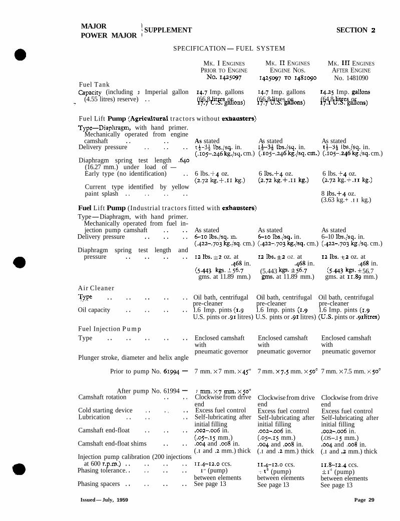
MAJOR 1 SUPPLEMENT POWER MAJOR r
SECTION 2
SPECIFICATION-FUEL SYSTEM
MK. I ENGINES MK. I1 ENGINES MK. I11 ENGINES PRIOR TO ENGINE ENGINE NOS. AFTER ENGINE
No. 1425097 142597 TO 1481090 No. 1481090 Fuel Tank Capacity (including 1 Imperial gallon 14.7 Imp. gallons 14.7 Imp. gallons 14.25 Imp. gallons
(4.55 litres) reserve) . . (66.8 1' itres or (66.8 1' itres or (64.8 1' itres or ? 17.7U.S.gallons) 17.7U.S.gallons) 17.1U.S.gallons)
Fuel Lift Pump (Agricultural t ractors without exhausters) Type-Diaphragm, with hand primer.
Mechanically operated from engine camshaft . . . . As stated As stated As stated
Delivery pressure . . . . . . 13-36 lbs./sq. in. l&3$ lbs./sq. in. 14-54 lbs./sq. in. (.Io~-.246 kg./sq. cm.) (.Io~-.246 kg./sq. an.) (.Io~-.246 kg./sq. cm.)
Diaphragm spring test length .640 (16.27 mm.) under load of - Early type (no identification) . . 6 lbs. +4 oz. 6 lbs.+q oz. 6 lbs. + 4 oz.
(2.72kg.+.11kg.) (2.72kg.+.11kg.) (2.72kg.+.11kg.) Current type identified by yellow paint splash . . . . . . . . 8 lbs.+4 oz.
(3.63 kg.+ .I I kg.) Fuel Lift Pump (Industrial t ractors fitted with exhaustess) Type-Diaphragm, with hand primer.
Mechanically operated from fuel in- jection pump camshaft . . . . As stated As stated As stated
Delivery pressure . . . . . . 6-10 lbs./sq. in. 6-10 lbs./sq. in. 6-10 lbs./sq. in. (.422-.703 kg./sq. cm.) (.422-,703 kg./sq. cm.) (.422-.703 kg./sq. cm.)
Diaphragm spring test length and pressure . . . . . . . . 12 lbs. &2 oz. at 12 lbs. &2 OZ. at 12 lbs. _t2 oz. at
,468 in. .468 in. .468 in. (5.443 kgs. 556.7 (5.443 kgs. h56.7 (5.443 kgs. 56.7 gms. at 11.89 mm.) g m . at 11.89 mm.) gms. at 11.89 mm.)
Air Cleaner Type .. . . . . . . . . Oil bath, centrifugal Oil bath, centrifugal Oil bath, centrifugal
pre-cleaner pre-cleaner pre-cleaner Oil capacity . . . . . . . . 1.6 Imp. pints (1.9 1.6 Imp. pints (1.9 1.6 Imp. pints (1.9
U.S. pints or .g1 litres) U.S. pints or .g1 litres) ( U S . pints or .g~litres)
Fuel Injection P u m p Type . . . . . . . . . . Enclosed camshaft Enclosed camshaft Enclosed camshaft
with with with pneumatic governor pneumatic governor pneumatic governor
Plunger stroke, diameter and helix angle
Prior to pump No. 61994 - 7 mm. X 7 mm. x45" 7 mm. x7.5 mm. X 50" 7 mm. X 7.5 mm. X p "
After pump No. 61994 - r mm.x7 mm.x50u Camshaft rotation . . . . Clockwise from drive
end Cold starting device . . . , . . Excess fuel control Lubrication . . . . . . Self-lubricating after
initial filling Camshaft end-float . . . . . . ,002-,006 in.
(.OS-.IS mm.) Camshaft end-float shims . . . . .004 and .008 in.
(.I and .2 mm.) thick Injection pump calibration (200 injections
at 600 r.p.m.) . . . . . . . . 11.4-12.0 ccs. Phasing tolerance. . , . . . . . I" (pump)
between elements Phasing spacers . . . . . . . . See page 13
Clockwise from drive end Excess fuel control Self-lubricating after initial filling ,002-.oo6 in. (.05-.15 mm.) .oo4 and .008 in. (.I and .2 mm.) thick
11.4-12.0 ccs. -1 I" (pump) between elements See page 13
Clockwise from drive end Excess fuel control Self-lubricating after initial filling .oo2-.oo6 in. (.OS-.I 5 mm.) ,004 and .008 in. (.I and .2 mm.) thick
11.8-12.4 ccs. i I O (pump) between elements See page 13
Issued-July, 1959 Page 29
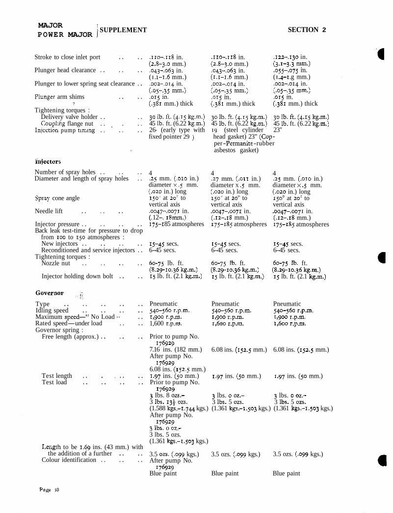
MAJOR I
POWER MAJOR 1 SUPPLEMENT SECTION 2
Stroke to close inlet port . . . . Plunger head clearance . . . . . . Plunger to lower spring seat clearance . . Piunger arm shims . . . .
?
Tightening torques : Delivery valve holder . . . . Coupl~ng flange nut . . . . .
Inlection pump tlnxng . . . . . .
Injectors
Number of spray holes . . . . . . Diameter and length of spray holes . .
Spray cone angle
Needle lift . . . . . . Injector pressure . . . . . . . . Back leak test-time for pressure to drop
from IOO to 150 atmospheres : New injectors . . . . . . . . Reconditioned and service injectors . .
Tightening torques : Nozzle nut . . . . . . . .
Injector holding down bolt . . . .
Type . . . . . . . . . . Idling speed . . . . . . . . Maximum speed-" No Load " . . Rated speed-under load . . . . Governor spring :
Free length (approx.) . . . . . .
Test length . . . . . . . . Test load . . . . . . . .
Length to be 1.69 ins. (43 mm.) with the addition of a further . . . .
Colour identification . . . . . .
.IIO-,118 in. (2.8-3.0 mm.) .043-,063 in. ( I . 1-1.6 mm.) .oo2-.OI~ in. (-05-:35 mm.) .o15 In. (.381 mm.) thick
. I IO-. I I~ in. (2.8-3.0 mm.) ,043-.063 in. (1.1-1.6 mm.) .oo~-.o14 in. (-05-:35 mm.) ,015 m. (.381 mm.) thick
,122-.13o in. (3.1-3.3 mm.) .o55-.075 m. (I .4-I .g mm.) .oo2-,014 in. (.05-:35 mm.) ,015 m. (.381 mm.) thick
30lb.ft.(4.15kg.m.) 3olb.ft.(4.15kg.m.) 3olb.ft.(4.15kg.m.) 45 lb. ft. (6.22 kg.m.) 45 lb. ft. (6.22 kg.m.) 45 lb. ft. (6.22 kg.m.) 26- (early type with 19 (steel cylinder 23" fixed pointer 29 ) head gasket) 23" (Cop-
per -Permanite -rubber asbestos gasket)
4 .25 mm. (-010 in.) diameter x .5 mm. (.020 in.) long 150- at 20' to vertical axis .oo47-.oo71 in. (. 12-. 18mm.) 175-1 85 atmospheres
4 .27 mm. (.OII in.) diameter X .5 mm. (.020 in.) long 150' at 20' to vertical axis .0047-.oo71 in. (.12-.18 mm.) 175-185 atmospheres
4 .25 mm. (.OIO in.) diameter x .5 mm. (.o2o in.) long 150' at 20' to vertical axis .0047-.oo7 I in. (.12-.18 mm.) 175-185 atmospheres
15-45 secs. 15-45 secs. 15-45 secs. 6-45 secs. 6-45 secs. 6-45 secs.
60-75 lb. ft. 60-75 lb. ft. 60-75 lb. ft. (8.29-10.36 kg.m.) (8.29-10.36 kg.m.) (8.29-10.36 kgm.) 15 lb. ft. (2.1 kg.m.) 15 lb. ft. (2.1 kg.m.) 15 lb. ft. (2.1 kg.m.)
Pneumatic Pneumatic Pneumatic 540-560 r.p.m. 540-560 r.p.m. 540-560 r.p.m. 1,900 r.p.m. 1,900 r.p.m. 1,900 r.p.m. 1,600 r.p.m. 1,600 r.p.m. 1,600 r.p.m,
Prior to pump No. 176929
7.16 ins. (182 mm.) 6.08 ins. (152.5 mm.) 6.08 ins. (152.5 mm.) After pump No.
176929 6.08 ins. (152.5 mm.) 1.97 ins. (50 mm.) 1.97 ins. (50 mm.) 1.97 ins. (50 mm.) Prior to pump No.
176929 3 Ibs. 8 02s.- 3 lbs. o oz.- 3 lbs. o oz.- 3 IbS. 134 02s. 3 1bS. 5 02s. 3 Ibs. 5 02s. (1.588 kgs.-1.744 kgs.) (1.361 kgs.-1.503 kgs.) (1.361 kgs.-1.503 kgs.) After pump No.
176929 3 Ibs. o oz.- 3 lbs. 5 ozs. (1.361 kgs.-1.503 kgs.)
3.5 ozs. (.egg kgs.) 3.5 ozs. (.egg kgs.) 3.5 ozs. (.ogg kgs.) After pump No.
176929 Blue paint Blue paint Blue paint