Embed Size (px)
Citation preview
Instruction Manual SDI-TG-EL-D4A-xx-x-0 page 1 of 36 Revised 1/19/11 Preferred Utilities Manufacturing Corporation
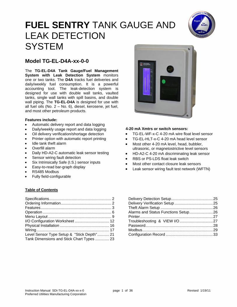
FUEL SENTRY TANK GAUGE AND LEAK DETECTION SYSTEM Model TG-EL-D4A-xx-0-0 The TG-EL-D4A Tank Gauge/Fuel Management System with Leak Detection System monitors one or two tanks. The D4A tracks fuel deliveries and daily/weekly fuel consumption. It is a powerful accounting tool. The leak-detection system is designed for use with double wall tanks, vaulted tanks, single wall tanks with spill basins, and double wall piping. The TG-EL-D4A is designed for use with all fuel oils (No. 2 – No. 6), diesel, kerosene, jet fuel, and most other petroleum products. Features include: Automatic delivery report and data logging Daily/weekly usage report and data logging Oil delivery verification/shortage detection Printer option with automatic report printing Idle tank theft alarm Overfill alarm Daily HD-A2-C automatic leak sensor testing Sensor wiring fault detection Six Intrinsically Safe (I.S.) sensor inputs Easy-to-read bar-graph display RS485 Modbus Fully field-configurable
4-20 mA Xmtrs or switch sensors: TG-EL-WF-x-C 4-20 mA wire float level sensor TG-EL-HLT-x-C 4-20 mA head level sensor Most other 4-20 mA level, head, bubbler,
ultrasonic, or magnetostrictive level sensors HD-A2-C 4-20 mA discriminating leak sensor RBS or PS-LDS float leak switch Most other contact closure leak sensors Leak sensor wiring fault test network (WFTN)
Table of Contents Specifications.......................................................... 2 Ordering Information............................................... 2 Features.................................................................. 3 Operation ................................................................ 6 Menu Layout ........................................................... 9 I/O Configuration Worksheet ................................ 12 Physical Installation .............................................. 16 Wiring.................................................................... 17 Level Sensor Type Setup & "Stick Depth"........... 21 Tank Dimensions and Stick Chart Types ............. 23
Delivery Detection Setup.......................................25 Delivery Verification Setup ....................................25 Theft Alarm Setup .................................................26 Alarms and Status Functions Setup......................26 Printer....................................................................27 Troubleshooting & VIEW I/O ...............................27 Password...............................................................28 Modbus..................................................................29 Configuration Record ............................................33

Instruction Manual SDI-TG-EL-D4A-xx-x-0 page 2 of 36 Revised 1/19/11 Preferred Utilities Manufacturing Corporation
Specifications Inputs (10 total) Six multipurpose: 4-20 mA or contact closure Each channel field-configured Intrinsically Safe: Class 1, Zone 0, Group CD Voc = 29.9, Isc= 99.5mA, Po= .75W 2-wire 4-20 mA: 12.8 VDC min. for (xmtr + wiring) Contact closure: 10 VDC, 26 mA Resolution: 0.007% Accuracy: 0.1% Four contact closure: (1) 120 VAC, 10 mA (3) 15 VDC, 10 mA (w/ 1.5k external pullup) Outputs Six relays: (4) SPST NO, 1.5A pilot, 120 VAC (2) SPDT, 10A res., ½ Hp, 120 VAC Two 4-20 mA: 650 ohms max, volume or depth
Instrument Input power: 120 VAC +/-15%, 50/60 Hz, 26 VA Case size: TG-EL-D4A-00: 8”H x 3.5”W x 7.7”D
TG-EL-D4A-Ex: 13.8”H x 11.9”W x 9.1”D
Enclosure: Nema 13 faceplate Ambient temp.: 32° to 122° F Display: High-contrast LCD display 4" high, 0.5% resolution, bar graph Communications RS485: Modbus, ASCII or RTU 1200-38,400 baud Printer Input power: 120 VAC +/-15%, 50/60 Hz, 20 VA Size: 4.6"H x 4"W x 2.8"D Enclosure: Nema 1 Ambient temp.: 32° to 122° F Paper: 2.25" W, thermal, 30 columns
Ordering Information
Tank gauge TG-EL-D4A -___ -___ - 0
No enclosure, no printer 00 Wall-mount enclosure, no printer E0
Wall-mount enclosure, with printer EP
RS485 Modbus 0 Printer for panel mounting.......................TG-EL-D4A-PRINTER (Shipped loose; only used with TG-EL-D4A-00-x-0.) Wire float level sensor, 4-20 mA (See TG-EL-WF for dimensional information.) 7-ft. max. depth ............................................. TG-EL-WF-7-C 12-ft. max. depth ........................................... TG-EL-WF-12-C Submersible head level sensor, 4-20 mA 7-ft. max. depth, #2 oil and diesel ................ TG-EL-HLT-7-C 15-ft. max. depth, #2 oil and diesel .............. TG-EL-HLT-15-C Leak sensor, dry/water/oil, 4-20mA
25-ft. sensor .......................................................... HD-A2-C 8-ft. sensor .........................................................HD-A2-C-8
Sensor guard for HD-A2-C for sumps, vault floors, bright areas .................................................................. HD-HSG Leak sensor, float actuated, day tank, double wall pipe...... RBS Leak sensor, pump set leak float switch........................ PS-LDS Two-wire wiring fault test network ................................. WFTN-1 (For use with RBS, HLS, and other contact closure leak or level sensors. WFTN built into HD-A2, not req'd for HD-A2.) Two-wire direct burial cable...............................................92612 (For use with TG-EL-WF-x-C, RBS, HLS.) Four-wire vented direct burial cable ..................................26000 (For use with TG-EL-HLT-x-C.)
Instruction Manual SDI-TG-EL-D4A-xx-x-0 page 3 of 36 Revised 1/19/11 Preferred Utilities Manufacturing Corporation
Features The TG-EL-D4A can monitor tank volume (gallons or liters) and tank leak detectors for one or two tanks via 10 inputs (six Intrinsically Safe inputs and four auxiliary). Flexible, multipurpose Intrinsically Safe (I.S.) inputs: Each of the six I.S. input channels can be connected to either a two-wire 4-20 mA xmtr or a contact closure. A wide variety of ullage, depth, head, flow, discriminating leak, leak switch, fill alarm level switch, fill alarm silence PB switches and sensors can be field-configured from the TG-EL-D4A menus to be connected to any one of the six I.S. input channels. The 4-20 mA engineering units for the standard Preferred Utilities sensors are preloaded and automatically entered when one of these sensors is assigned to an input channel. Other I.S. 4-20 mA xmtrs can also be used (with manually configured engineering units). Fully field-configurable: The TG-EL-D4A can be completely configured in the field from its LCD menus. A laptop is not required to configure the TG-EL-D4A. Gallons (or liters) volume calculation based on: a) One of five standard tank shapes with user-entered tank dimensions (inches or centimeters), or b) A user-entered volume-vs.-depth stick chart (up to 51 points), typically from tank mfg. stick chart data. The D4A can print a stick chart for either dimension-based or manual stick chart-based calculations. Delivery detection and data logging: The TG-EL-D4A automatically detects a delivery and stores the delivered volume in a time/date-stamped data-logger nonvolatile memory. For a dual-tank system, the last seven deliveries for each tank are stored. For a single-tank system, the last 14 deliveries are stored. The printer can be configured to automatically print a time/date-stamped “Gallons Delivered” report after the delivery that can be used to verify the invoice before payment. The complete delivery history can be viewed from the TG-EL-D4A LCD screen and is also available via Modbus. Delivery verification and shortage detection: With the high price of oil, it is important to pay for only what is actually delivered. The delivery data logging and reports are the first level of verification. This is accomplished with a single fluid-depth sensor per tank. If a secondary sensor is installed, the D4A provides more sophisticated verification. The D4A supports three primary/secondary sensor combinations:
Level (primary)/head (secondary) Level (primary)/flow (secondary) Head (primary)/flow (secondary)
A level sensor directly measures the fluid depth with TG-EL-WF wire float, ultrasonic, float-based magnetostrictive sensors, and others. A flow sensor is installed in the delivery pipe and directly measures the delivered fluid volume. A head sensor measures the weight (pressure) of the fluid at the bottom of the tank, calculates the fluid depth based on a user-entered specific gravity and then calculates the volume based on the derived depth. Head sensor-based volume is generally less accurate than level- or flow-based volume. The level/flow or head/flow combinations compare the tank volume difference before and after the delivery with the flow meter-measured volume. If the volume difference is larger than the user-adjusted threshold, the D4A notes the difference on the printed delivery report and records the difference in the alarm history (but does not trigger the alarm system). The level/head combination cross-checks a volumetric measurement against a weight-based measurement. Delivery “shorting” by air injection, or by waste fluid blending, changes the delivered oil density (i.e., specific gravity) and “fools” both the truck delivery meter volumetric measurement and level-based tank volume calculations, even with the most precise sensors. (continued on next page)

Instruction Manual SDI-TG-EL-D4A-xx-x-0 page 4 of 36 Revised 1/19/11 Preferred Utilities Manufacturing Corporation
Delivery verification and shortage detection (continued): The head sensor responds to fluid weight and will detect a “light” oil delivery due to air injection, or a “heavy” oil delivery due to waste oil blending. The TG-EL-D4A uses specialized head sensor compensation calculations at the time of each delivery to enhance the detection of specific gravity changes and notes a suspicious oil-density change on the “Gallons Delivered” printed report and in the alarm history (but does not trigger the alarm system). Usage monitoring and data logging: Every day at midnight, the TG-EL-D4A computes the usage for the previous day based on: tank volume at the previous midnight, the sum of all deliveries during the day, and the tank volume at the current midnight. The resulting daily usage is date-stamped and stored in the data-logger EEPROM memory. Every Sunday at midnight, the previous seven days are added together and stored as the weekly usage. The oldest data are overwritten by newer data. Usage data can be printed, viewed via the LCD menus, or read by Modbus. For a dual-tank system, the D4A stores the last seven individual days and the last four weeks’ usage for each tank. For a single-tank system, the D4A stores the last 14 individual days and the last eight weeks’ usage for each tank. Alarm history data logging: The TG-EL-D4A can be configured to generate a wide variety of alarms. Alarms are time- and date-stamped and then stored in the data-logger EEPROM memory. The alarm history can be printed, viewed via the LCD menus, or read by Modbus. The TG-EL-D4A stores the last 10 alarms regardless of how many tanks are configured. Theft alarm: Thefts are monitored in two ways: idle tank volume change and high usage rate. Idle tank: An idle tank will trigger a theft alarm if the volume drops an adjustable amount below the volume saved at the time the tank became idle. This mode requires a contact closure input that indicates when the tank is idle. This could be a manual valve auxiliary switch, a pump starter auxiliary switch, a flow switch, a diesel generator “not running” contact, or other means. High usage: The D4A monitors the tank volume every few minutes and calculates a short-term usage rate. If this rate is higher than a user-adjustable theft rate, a theft alarm will be triggered. This strategy assumes that the peak usage rate is known and that the theft is caused by a rapid, higher flow rate, or removal of oil. Fill alarm: When the tank is being filled and the volume exceeds the high-high volume setpoint, the TG-EL-D4A can be configured to activate a relay output. This, in turn, can activate an FA-AV-x-D3 (or similar) audible/visual fill alarm near the tank fill pipe to warn the driver to stop filling the tank before it overfills. This alarm self-silences after an adjustable time delay, or it can be manually silenced. The driver can test the fill alarm by pressing and holding the remote alarm silence button for more than five seconds. If the tank is not full, this test will trigger the fill alarm relay output. “Not Full” means the volume is lower than the high-high volume setpoint and the FILALM LS input is inactive (if configured). For dual-tank systems, the D4A can be configured for an individual fill alarm per tank, a common fill alarm for both tanks, individual or common fill alarm silence/test buttons, or any combination of individual/common devices. A fill alarm is not recorded in the alarm history, does not trigger the D4A, and does not cause the D4A bar graph to blink. The fill alarm is intended only to alert the tank truck driver. If these features are desired, enable the high-high alarm feature for the tank. A remote visual light for “Tank Full” indication can be implemented by configuring one of the relays as a high-high status relay. HD-A2-C discriminating leak alarms: HD-A2-C leak sensor inputs to the TG-EL-D4A can discriminate among the following conditions: dry, oil present, water present, shorted field wiring, and open-circuit field wiring. Any condition other than “dry” will trigger a leak alarm for that channel and be recorded in the alarm history with the channel number and the condition. Any type of leak alarm requires a manual reset after the condition has been cleared.
Instruction Manual SDI-TG-EL-D4A-xx-x-0 page 5 of 36 Revised 1/19/11 Preferred Utilities Manufacturing Corporation
HD-A2-C continuous self-test, daily test, and manually initiated test: All leak-detection systems must be periodically tested over the 20- to 30-year life of the tank to ensure that the leak-detection system will work if/when a leak occurs. The HD-A2-C continuously does self-tests, including testing the critical wet/dry light source and detector, and will change its output to non-dry if a problem is detected. Every midnight, the TG-EL-D4A commands all HD-A2-Cs to do a self-test and then tests each HD-A2 to determine if its output is falsely “stuck” at the “dry” output signal. This test also can be initiated at any time by an inspector from the main menu. Contact closure leak sensor field Wiring Fault Test Network (WFTN): Contact closure leak sensors open or close an internal switch contact to signal a leak or no-leak condition. Field wiring faults can prevent leak detection. An open circuit in the field wiring of a N.O. (normally open) leak sensor prevents leak detection. A short circuit in the field wiring of a N.C. (Normally Closed) leak sensor prevents leak detection. Installation of a WFTN (Wiring Fault Test Network) in the junction box of a contact closure leak sensor allows the TG-EL-D4A to continuously discriminate among these four conditions: no leak, leak, wiring open, or wiring short. Any condition other than “no leak” will trigger a leak alarm for that channel and be recorded in the alarm history with the channel number and the condition. Any type of leak alarm requires a manual reset after the condition has been cleared. Alarm and status functions: In addition to the fill alarm, theft alarm, and leak alarms discussed above, each tank has four volume-based alarm functions, four volume-based status functions, and two volume-based control functions. Alarm and status functions are very similar. The differences between an alarm and a status are:
Feature Alarm Status Triggers the common alarm yes no Causes the bar graph to blink yes no Silenced by the various alarm silence signals yes no Creates a time/date-stamped alarm history entry yes no Can be disabled via the configuration menus yes no Adjustable time delay (one adj. for all alarms) yes no Automatically resets after condition clears depends yes Turns on a Modbus coil yes yes Can be configured to energize an output relay yes yes
There are eight user-adjustable volume setpoints and one alarm delay seconds parameter: HIGH-HIGH T1, HIGH T1, LOW T1, LOW-LOW T1, HIGH-HIGH T2, HIGH T2, LOW T2, and LOW-LOW T2. Each setpoint is used by both an alarm function and a status function, and sometimes by other functions. The setpoint name describes the logic: HIGH-HIGH setpoint: If the volume is higher than the HIGH-HIGH setpoint for more than the alarm delay
seconds, a HIGH-HIGH alarm is triggered. HIGH-HIGH setpoint: If the volume is higher than the HIGH-HIGH setpoint, a HIGH-HIGH status is triggered.. LOW setpoint: If the volume is lower than the LOW setpoint, a LOW status is triggered. Other setpoint uses: The HIGH-HIGH setpoint triggers the fill alarm function described above. FILL function: If volume < LOW setpoint, FILL turns ON. If volume > HIGH setpoint, FILL turns OFF. If both conditions are true, FILL turns OFF. DRAIN function: If volume > HIGH setpoint, DRAIN turns ON. If volume < LOW setpoint, DRAIN turns OFF. If both conditions are true, DRAIN turns ON.
Instruction Manual SDI-TG-EL-D4A-xx-x-0 page 6 of 36 Revised 1/19/11 Preferred Utilities Manufacturing Corporation
None of the alarms or statuses energizes any particular relay output channel. The six output relays are energized by the alarm or status function selected by the user during configuration. See the RELAY CONFIG menu. RS485 Modbus: The current depths, volumes, alarms, and statuses can be read via Modbus. The last 10 alarms and all of the delivery and usage data-logger data can be read via Modbus. See the table at the end of the manual. Printer: There are three printer reports: short, long, and stick chart. The short report includes for each tank: current depth and volume; volume, usage, and HD-A2 test results at previous midnight; last delivery; and all alarms that occurred within the last 24 hours. The long report includes for each tank: the 14 latest deliveries, the 14 last daily consumptions, the eight last weekly consumptions, and the last 10 alarms. The stick chart report shows the volume at various depth intervals, one tank per report. The depth interval is user-configured, with a maximum of 50 evenly spaced depths, plus the full volume and depth.
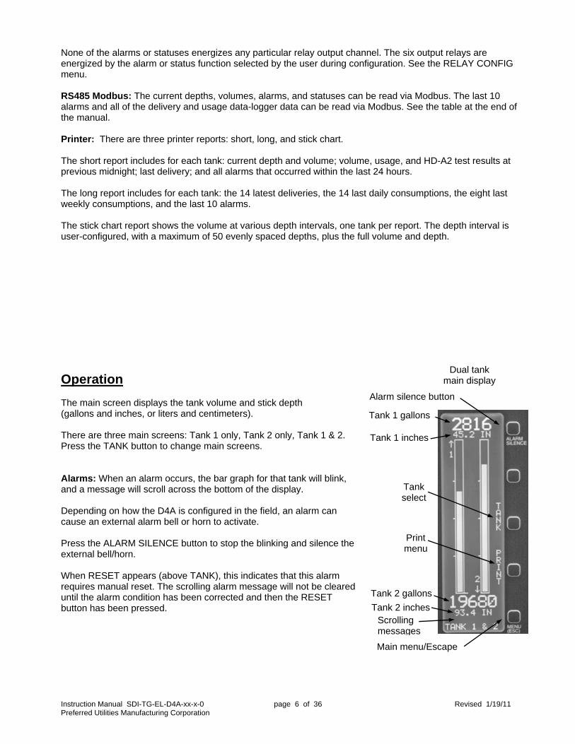
Operation The main screen displays the tank volume and stick depth (gallons and inches, or liters and centimeters). There are three main screens: Tank 1 only, Tank 2 only, Tank 1 & 2. Press the TANK button to change main screens. Alarms: When an alarm occurs, the bar graph for that tank will blink, and a message will scroll across the bottom of the display. Depending on how the D4A is configured in the field, an alarm can cause an external alarm bell or horn to activate. Press the ALARM SILENCE button to stop the blinking and silence the external bell/horn. When RESET appears (above TANK), this indicates that this alarm requires manual reset. The scrolling alarm message will not be cleared until the alarm condition has been corrected and then the RESET button has been pressed.
Scrolling messages
Tank 1 inches
Tank 1 gallons
Dual tank main display
Main menu/Escape
Tank select
Print menu
Alarm silence button
Tank 2 gallons
Tank 2 inches
Instruction Manual SDI-TG-EL-D4A-xx-x-0 page 7 of 36 Revised 1/19/11 Preferred Utilities Manufacturing Corporation
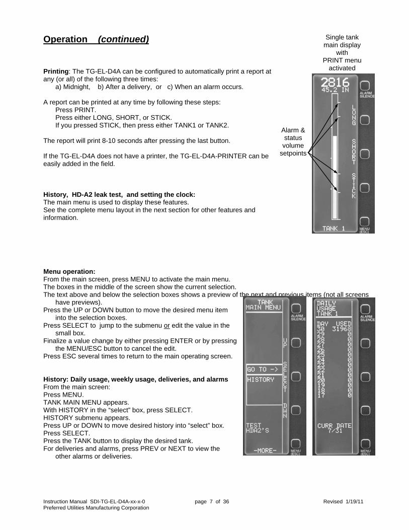
Single tankmain display
with PRINT menu
activated
Alarm & status volume
setpoints
Operation (continued) Printing: The TG-EL-D4A can be configured to automatically print a report at any (or all) of the following three times: a) Midnight, b) After a delivery, or c) When an alarm occurs. A report can be printed at any time by following these steps:
Press PRINT. Press either LONG, SHORT, or STICK. If you pressed STICK, then press either TANK1 or TANK2.
The report will print 8-10 seconds after pressing the last button. If the TG-EL-D4A does not have a printer, the TG-EL-D4A-PRINTER can be easily added in the field. History, HD-A2 leak test, and setting the clock: The main menu is used to display these features. See the complete menu layout in the next section for other features and information. Menu operation: From the main screen, press MENU to activate the main menu. The boxes in the middle of the screen show the current selection. The text above and below the selection boxes shows a preview of the next and previous items (not all screens
have previews). Press the UP or DOWN button to move the desired menu item
into the selection boxes. Press SELECT to jump to the submenu or edit the value in the
small box. Finalize a value change by either pressing ENTER or by pressing
the MENU/ESC button to cancel the edit. Press ESC several times to return to the main operating screen. History: Daily usage, weekly usage, deliveries, and alarms From the main screen: Press MENU. TANK MAIN MENU appears. With HISTORY in the “select” box, press SELECT. HISTORY submenu appears. Press UP or DOWN to move desired history into “select” box. Press SELECT. Press the TANK button to display the desired tank. For deliveries and alarms, press PREV or NEXT to view the
other alarms or deliveries.
Instruction Manual SDI-TG-EL-D4A-xx-x-0 page 8 of 36 Revised 1/19/11 Preferred Utilities Manufacturing Corporation
Alarm data: Some alarms store auxiliary data. Alarm/Event Data 1 Data 2 Tank 1 Theft Alarm (Idle Tank) Initial Volume Volume at Alarm Tank 1 Theft Alarm (High Comsumption) gpm (or lpm) rate Initial Volume Tank 1 Leak Alarm Channel Status (see below) Tank 1 Lk HD-A2 Test Failed Channel (not used) Tank 1 Delivery Changed Specific Gravity Sp. gravity before
delivery Sp. gravity after delivery
Tank 1 Pri & Sec Delivery Vol Difference Primary sensor delivery volume
Secondary sensor delivery volume
Tank 1 Delivery Changed Specific Gravity Primary sensor delivery volume
Flow meter delivery volume
Tank 1 Delivery Level and Flow Total Differ
Leak Sensor Status: 0=Inactive, 1=Active, 2=Field Wiring Open, 3=Field Wiring Short, 4=Oil, 5=Water, 6=Dry, 7=Test, 8= Sensor Configuration Error
Power outages can affect usage data: Daily and weekly usage data are calculated at midnight. Power outage scenarios include:
After power is restored: Usage is calculated from when power came back ON until the next midnight. Power off at midnight: Usage is not calculated, and 0 is recorded in all “missed” days upon power up. Power off Sunday midnight: Weekly usage is not calculated.
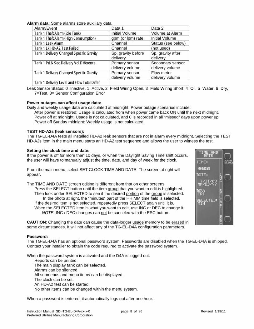
TEST HD-A2s (leak sensors): The TG-EL-D4A tests all installed HD-A2 leak sensors that are not in alarm every midnight. Selecting the TEST HD-A2s item in the main menu starts an HD-A2 test sequence and allows the user to witness the test. Setting the clock time and date: If the power is off for more than 10 days, or when the Daylight Saving Time shift occurs, the user will have to manually adjust the time, date, and day of week for the clock. From the main menu, select SET CLOCK TIME AND DATE. The screen at right will appear. The TIME AND DATE screen editing is different from that on other screens.
Press the SELECT button until the item group that you want to edit is highlighted. Then look under SELECTED to see if the desired portion of the group is selected.
In the photo at right, the “minutes” part of the HH:MM time field is selected. If the desired item is not selected, repeatedly press SELECT again until it is. When the SELECTED item is what you want to edit, use INC or DEC to change it.
NOTE: INC / DEC changes can not be canceled with the ESC button. CAUTION: Changing the date can cause the data-logger usage memory to be erased in some circumstances. It will not affect any of the TG-EL-D4A configuration parameters. Password: The TG-EL-D4A has an optional password system. Passwords are disabled when the TG-EL-D4A is shipped. Contact your installer to obtain the code required to activate the password system. When the password system is activated and the D4A is logged out:
Reports can be printed. The main display tank can be selected. Alarms can be silenced. All submenus and menu items can be displayed. The clock can be set. An HD-A2 test can be started. No other items can be changed within the menu system.
When a password is entered, it automatically logs out after one hour.

Instruction Manual SDI-TG-EL-D4A-xx-x-0 page 9 of 36 Revised 1/19/11 Preferred Utilities Manufacturing Corporation
Menu Layout
HI STORY
TESTHDA2' S
SET CLOCKTI ME ANDDATE
CONFI GURETANKGAUGE
MODBUS
VI EW I / O
LCDCONTRAST
TANKMAI N MENU
DAI LYUSAGE
WEEKLYUSAGE
RECENTDELI VERY
ALARMHI STORY
HI STORY
DATE USED 5 1231 4 1793 3 2317 2 1987 1 98730 113529 4512
DAI LYUSAGETANK 1
TANK2
DATE USED 5 2314 4 2107 3 1723 2 1787 1 101330 125429 5421
DAI LYUSAGETANK 2
TANK1
DATE USED 7/ 05 37132 6/ 28 103567 6/ 21 43917 6/ 14 33973
WEEKLYUSAGETANK 1
TANK
DATE USED 7/ 05 47594 6/ 28 1587 6/ 21 49717 6/ 14 51673
WEEKLYUSAGETANK 2
TANK
TI ME: 16: 21
DATE: 7/ 6/ 09 MM/ DD/ YY
DAY: MON
SELECTED: HOUR
TI ME AND DATE
INC
SELECT
DEC
PROTOCOLASCI I , RTU
ADDRESS
BAUD RATE
PARI TY
MODBUSMENU
DELI VERY 1DATE 07/ 05TI ME 11: 31GALLONS 5917
RECENTDELI VERYTANK 1
NEXT
TANK
PREV
DELI VERY 1DATE 07/ 04TI ME 15: 27GALLONS 5831
RECENTDELI VERYTANK 2
NEXT
TANK
PREV
- - - I / O- - -I NPUT 1T51- T52 7. 90
I NPUT 2T54- T55 12. 90
I NPUT 3T56- T57 17. 21
I NPUT 4T59- T60 25. 90
I NPUT 5T61- T62 0. 00
I NPUT 6T65- T65 9. 70
PREV
NEXT
CH 1- - - N/ A- - -
CH 2- - - N/ A- - -
CH 3 HDA2 DRY
CH 4 HDA2 DRY
CH 5 HDA2 DRY
CH 6- - - N/ A- - -
HDA2 LEAKSENSORTESTI NG
TEST
DATE 7/ 20TI ME 14: 30
TANK 1HDA2 OI LLEAK
ALARMHI STORY
NEXT
PREV
to Configure Menu
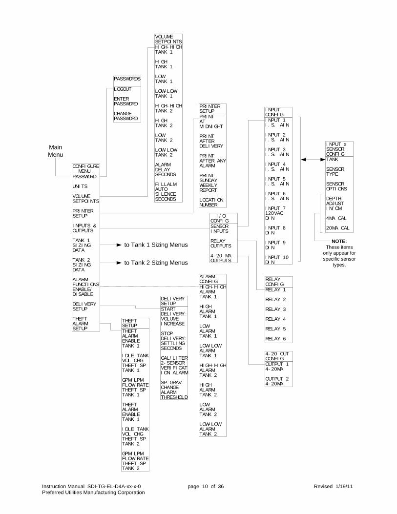
Instruction Manual SDI-TG-EL-D4A-xx-x-0 page 10 of 36 Revised 1/19/11 Preferred Utilities Manufacturing Corporation
PASSWORD
UNI TS
VOLUMESETPOI NTS
PRI NTERSETUP
I NPUTS &OUTPUTS
TANK 1SI ZI NGDATA
TANK 2SI ZI NGDATA
ALARMFUNCTI ONSENABLE/DI SABLE
DELI VERYSETUP
THEFTALARMSETUP
CONFI GURE MENU
HI GH- HI GHTANK 1
HI GHTANK 1
LOWTANK 1
LOW- LOWTANK 1
HI GH- HI GHTANK 2
HI GHTANK 2
LOWTANK 2
LOW- LOWTANK 2
ALARMDELAYSECONDS
FI LLALMAUTOSI LENCESECONDS
VOLUMESETPOI NTS
HI GH- HI GHALARMTANK 1
HI GHALARMTANK 1
LOWALARMTANK 1
LOW- LOWALARMTANK 1
HI GH- HI GHALARMTANK 2
HI GHALARMTANK 2
LOWALARMTANK 2
LOW- LOWALARMTANK 2
ALARMCONFI G
PRI NTATMI DNI GHT
PRI NTAFTERDELI VERY
PRI NTAFTER ANYALARM
PRI NTSUNDAYWEEKLYREPORT
LOCATI ONNUMBER
PRI NTERSETUP
SENSORI NPUTS
RELAYOUTPUTS
4- 20 MAOUTPUTS
I / OCONFI G
I NPUT 1I . S. AI N
I NPUT 2I . S. AI N
I NPUT 3I . S. AI N
I NPUT 4I . S. AI N
I NPUT 5I . S. AI N
I NPUT 6I . S. AI N
I NPUT 7120VACDI N
I NPUT 8DI N
I NPUT 9DI N
I NPUT 10DI N
I NPUTCONFI G
RELAY 1
RELAY 2
RELAY 3
RELAY 4
RELAY 5
RELAY 6
RELAYCONFI G
OUTPUT 14- 20MA
OUTPUT 24- 20MA
4- 20 OUTCONFI G
STARTDELI VERY:VOLUMEI NCREASE
STOPDELI VERY:SETTLI NGSECONDS
GAL/ LI TER2- SENSORVERI FI CATI ON ALARM
SP. GRAV.CHANGEALARMTHRESHOLD
DELI VERYSETUP
THEFTALARMENABLETANK 1
I DLE TANKVOL CHGTHEFT SPTANK 1
GPM/ LPMFLOW RATETHEFT SPTANK 1
THEFTALARMENABLETANK 1
I DLE TANKVOL CHGTHEFT SPTANK 2
GPM/ LPMFLOW RATETHEFT SPTANK 2
THEFTSETUP
MainMenu
to Tank 1 Sizing Menus
to Tank 2 Sizing Menus
TANK
SENSORTYPE
SENSOROPTI ONS
DEPTHADJUSTI N/ CM
4MA CAL
20MA CAL
I NPUT xSENSORCONFI G
NOTE:These items
only appear forspecific sensor
types.
LOGOUT
ENTERPASSWORD
CHANGEPASSWORD
PASSWORDS
Instruction Manual SDI-TG-EL-D4A-xx-x-0 page 11 of 36 Revised 1/19/11 Preferred Utilities Manufacturing Corporation
NEXT
SELECT
PREV
TANK- 1STI CKCHARTTYPE
TANK- 1DI MENSI ONAND DATAENTRY
COMPUTEDFULLVOLUME
CALC STI KCHART FORPRI NTERCAUTI ON! !
TANK 1SI ZI NG
STI CKSTRI KERPLATETHI CKNESS
TANKDI AMETER
TANKOVERALLLENGTH
DI SH TANKSTRAI GHTLENGTH
SPECI FI CGRAVI TY
TANK 1 DATA
STI CKSTRI KERPLATETHI CKNESS
OBROUNDOVERALLLENGTH
OBROUNDOVERALLWI DTH
OBROUNDOVERALLHEI GHT
NUMBER OFTANKS I NPARALLEL
SPECI FI CGRAVI TY
TANK 1 DATA
STI CKSTRI KERPLATETHI CKNESS
FULLDEPTH
FULLVOLUME
SPECI FI CGRAVI TY
TANK 1 DATA
FULLDEPTH
FULLVOLUME
DEPTHI NTERVAL
EDI TSTI CKCHART
SPECI FI CGRAVI TY
TANK 1 DATA
TOTALVOLUME: 4953I NTERVAL: 1. 0
DEPTH 12. 0
713GALLONS
NOTE: USENEXT/ PREVTO CHANGEDEPTH
TANK 1CHART
Stick Chart Type =FLAT HORIZ or DISH HORIZ
Stick Chart Type =H OBROUND or V OBROUND
Stick Chart Type =LIN/VERT
Stick Chart Type =STIK CHRT
Note:'SPECIFIC GRAVITY' is only displayed if a'Head Level' Sensor is confgured for this
Tank. (typ. for all TANK x DATA screens)
Instruction Manual SDI-TG-EL-D4A-xx-x-0 page 12 of 36 Revised 1/19/11 Preferred Utilities Manufacturing Corporation
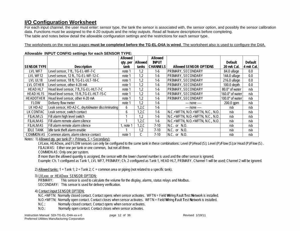
I/O Configuration Worksheet For each input channel, the user must enter: sensor type, the tank the sensor is associated with, the sensor option, and possibly the sensor calibration data. Functions must be assigned to the 4-20 outputs and the relay outputs. Read all feature descriptions before completing. The table and notes below detail the allowable configuration settings and the restrictions for each sensor type. The worksheets on the next two pages must be completed before the TG-EL-D4A is wired. The worksheet also is used to configure the D4A. Allowable INPUT CONFIG settings for each SENSOR TYPE:
SENSOR TYPE Description
Allowed qty. per
tank Allowed
tanks
Allowed INPUT
CHANNELS Allowed SENSOR OPTIONS Default
20 mA Cal. Default
4 mA Cal. LVL WF7 Level sensor, 7 ft., TG-EL-WF-7-C note 1 1,2 1-6 PRIMARY, SECONDARY 84.0 ullage 0.0 LVL WF12 Level sensor, 12 ft., TG-EL-WF-12-C note 1 1,2 1-6 PRIMARY, SECONDARY 144.0 ullage 0.0 LVL UL18 Level sensor, 18 ft, TG-EL-ULT-18-C note 1 1,2 1-6 PRIMARY, SECONDARY 216.0 ullage 0.0
LVL OTHER Level sensor, other 4-20 mA note 1 1,2 1-6 PRIMARY, SECONDARY 100.0 depth 0.0 HEAD HL7 Head level sensor, 7 ft.,TG-EL-HLT-7-C note 1 1,2 1-6 PRIMARY, SECONDARY 80.0" of water n/a HEAD HL15 Head level sensor, 15 ft.,TG-EL-HLT-15-C note 1 1,2 1-6 PRIMARY, SECONDARY 160.0" of water n/a
HEADOTHER Head level sensor, other 4-20 mA note 1 1,2 1-6 PRIMARY, SECONDARY 100.0" of water n/a FLOW Delivery flow meter note 1 1,2 1-6 --- none ---- 200.0 gpm n/a
LK HD-A2 Leak sensor, HD-A2-C, dry/oil/water discriminating 6 1,2,C 1-6 --- none ---- n/a n/a LK CONTAC Leak sensor, switch contact 6 1,2,C 1-6 N.C.+WFTN, N.O.+WFTN, N.C., N.O. n/a n/a FILALM LS Fill alarm high level switch 1 1,2 1-6 N.C.+WFTN, N.O.+WFTN, N.C., N.O. n/a n/a FILALM AS Fill alarm remote alarm silence 1 1,2,C 1-6 N.C.+WFTN, N.O.+WFTN, N.C., N.O. n/a n/a FILALM AS Fill alarm remote alarm silence 1, note 1 1,2,C 7-10 N.C. or N.O. n/a n/a IDLE TANK Idle tank theft alarm enable 1 1,2 7-10 N.C. or N.O. n/a n/a
COMMON AS Common alarm, alarm silence contact note 1 C 7-10 N.C. or N.O. n/a n/a Notes: 1) Allowed qty. per tank (P = Primary, S = Secondary):
LVLxxx, HEADxxx, and FLOW sensors can only be configured to the same tank in these combinations: Level (P)/Head (S); Level (P)/Flow (S);or Head (P)/Flow (S) . FILALM AS: Either one per tank or one common, but not all three. COMMON AS: Only one per system. If more than the allowed quantity is assigned, the sensor with the lower channel number is used and the other sensor is ignored. Example: Ch. 1 configured as Tank 1, LVL WF7, PRIMARY; Ch. 2 configured as Tank 1, HEAD HL7, PRIMARY. Channel 1 will be used; Channel 2 will be ignored.
2) Allowed tanks: 1 = Tank 1; 2 = Tank 2; C = common area or piping (not related to a specific tank).
3) LVLxxx or HEADxxx SENSOR OPTION: PRIMARY: This sensor is used to calculate the volume for the display, alarms, status relays and Modbus. SECONDARY: This sensor is used for delivery verification.
4) Contact input SENSOR OPTION: N.C.+WFTN: Normally closed contact. Contact opens when sensor activates. WFTN = Field Wiring Fault Test Network is installed. N.O.+WFTN: Normally open contact. Contact closes when sensor activates. WFTN = Field Wiring Fault Test Network is installed. N.C.: Normally closed contact. Contact opens when sensor activates. N.O.: Normally open contact. Contact closes when sensor activates.
Instruction Manual SDI-TG-EL-D4A-xx-x-0 page 13 of 36 Revised 1/19/11 Preferred Utilities Manufacturing Corporation
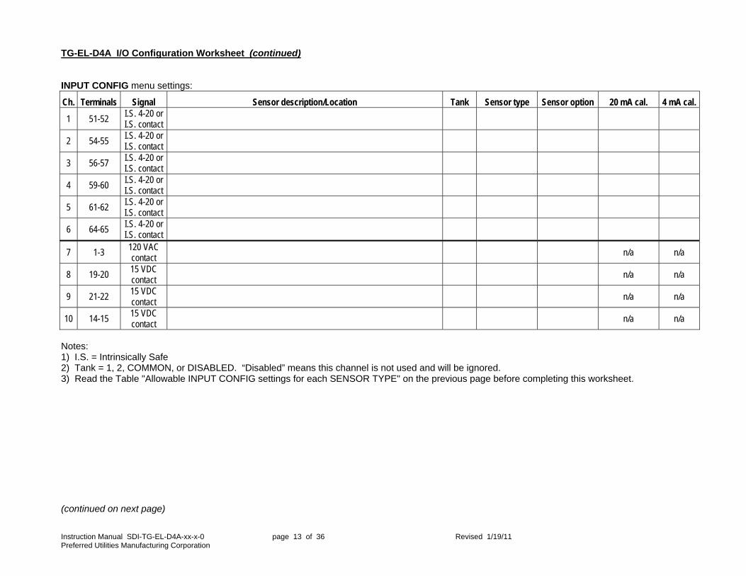
TG-EL-D4A I/O Configuration Worksheet (continued) INPUT CONFIG menu settings:
Ch. Terminals Signal Sensor description/Location Tank Sensor type Sensor option 20 mA cal. 4 mA cal.
1 51-52 I.S. 4-20 or I.S. contact
2 54-55 I.S. 4-20 or I.S. contact
3 56-57 I.S. 4-20 or I.S. contact
4 59-60 I.S. 4-20 or I.S. contact
5 61-62 I.S. 4-20 or I.S. contact
6 64-65 I.S. 4-20 or I.S. contact
7 1-3 120 VAC contact
n/a n/a
8 19-20 15 VDC contact n/a n/a
9 21-22 15 VDC contact
n/a n/a
10 14-15 15 VDC contact n/a n/a
Notes: 1) I.S. = Intrinsically Safe 2) Tank = 1, 2, COMMON, or DISABLED. “Disabled” means this channel is not used and will be ignored. 3) Read the Table "Allowable INPUT CONFIG settings for each SENSOR TYPE" on the previous page before completing this worksheet. (continued on next page)

Instruction Manual SDI-TG-EL-D4A-xx-x-0 page 14 of 36 Revised 1/19/11 Preferred Utilities Manufacturing Corporation
TG-EL-D4A I/O Channel Configuration Worksheet (continued) 4-20 mA Outputs Configuration 4-20 mA Output Functions: ("X" = “1” or “2”)
DISABLED Not used TX VOL Tank X volume 20 mA = full volume TX LVL Tank X level (fluid depth) 20 mA = tank diameter/full height/full depth
Relay Outputs Configuration: Relay Output Functions: ("X" = “1,” “2,” or “C” = Tank 1, Tank 2, or common/either tank )
Notes: If an "….. AL" (ie, alarm) function is assigned to a relay output, make sure the same alarm function is enabled in the ALARM CONFIG submenu.
Ch. Terminals Function 1 72-73
2 16-17
Name: X Description: Reset:
ALARM COM Common alarm, with alarm local or remote alarm silence Auto
LEAK COM Combined Tank 1 or 2 or common-area leak alarm Manual
LEAK X 1,2 Tank X leak alarm Manual
LEAK OTHR Common-area leak alarm Manual
FILLALM X 1,2,C Fill alarm, Tank X Auto
THEFT X 1,2 Tank X theft alarm Manual
HIHI X AL 1,2 Tank X high-high-volume alarm Auto
HI X AL 1,2 Tank X high-volume alarm Auto
LO X AL 1,2,C Tank X low-volume alarm Auto
LOLO X AL 1,2,C Tank X low-low-volume alarm Auto or manual configurable
HIHI X ST 1,2 Tank X high-high-volume status. Auto
HI X ST 1,2 Tank X high-volume status. Auto
LO X ST 1,2 Tank X low-volume status Auto
LOLO X ST 1,2 Tank X low-low-volume status Auto
FILL X 1,2 Tank X fill valve/pump Activates when volume drops below "Low" setpoint Deactivates when volume rises above "High" setpoint
Auto
DRAIN X 1,2 Tank X drain valve/pump Activates when volume rises above "High" setpoint Deactivates when volume drops below "Low" setpoint
Auto
Ch. Terminals Function
1 67-68
2 67-69
3 67-70
4 67-71
5 4-5-6
6 7-8-9

Instruction Manual SDI-TG-EL-D4A-xx-x-0 page 15 of 36 Revised 1/19/11 Preferred Utilities Manufacturing Corporation
TG-EL-D4A I/O Channel Configuration (continued) The I/O CONFIG menu items shown below are used to configure the TG-EL-D4A inputs and outputs based on the selections made on the "TG-EL-D4A I/O Channel Configuration Worksheet." A password must be entered before the TG-EL-D4A can be configured. The D4A is shipped with an initial default password. Obtain this password from your salesperson before installing the unit.
PASSWORD
UNI TS
VOLUMESETPOI NTS
PRI NTERSETUP
I NPUTS &OUTPUTS
TANK 1SI ZI NGDATA
TANK 2SI ZI NGDATA
ALARMFUNCTI ONSENABLE/DI SABLE
DELI VERYSETUP
THEFTALARMSETUP
CONFI GURE MENU
SENSORI NPUTS
RELAYOUTPUTS
4- 20 MAOUTPUTS
I / OCONFI G
I NPUT 1I . S. AI N
I NPUT 2I . S. AI N
I NPUT 3I . S. AI N
I NPUT 4I . S. AI N
I NPUT 5I . S. AI N
I NPUT 6I . S. AI N
I NPUT 7120VACDI N
I NPUT 8DI N
I NPUT 9DI N
I NPUT 10DI N
I NPUTCONFI G
RELAY 1
RELAY 2
RELAY 3
RELAY 4
RELAY 5
RELAY 6
RELAYCONFI G
OUTPUT 14- 20MA
OUTPUT 24- 20MA
4- 20 OUTCONFI G
TANK
SENSORTYPE
SENSOROPTI ONS
DEPTHADJUSTI N/ CM
4MA CAL
20MA CAL
I NPUT xSENSORCONFI G
NOTE:These items
only appear forspecific sensor
types.
HI STORY
TESTHDA2' S
SET CLOCKTI ME ANDDATE
CONFI GURETANKGAUGE
MODBUS
VI EW I / O
LCDCONTRAST
TANKMAI N MENU

Instruction Manual SDI-TG-EL-D4A-xx-x-0 page 16 of 36 Revised 1/19/11 Preferred Utilities Manufacturing Corporation
Physical Installation
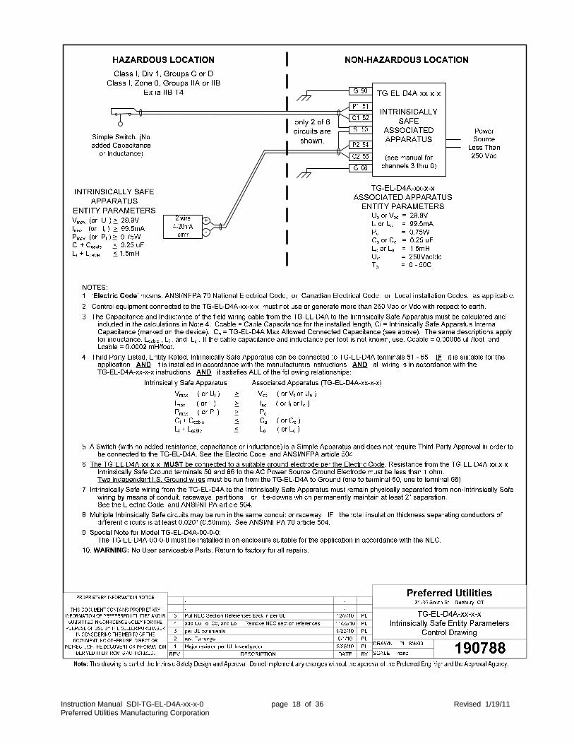
WARNING Failure to follow all procedures in this manual, on drawing 190788, and in the instruction manuals of all Intrinsically Safe sensors connected to the TG-EL-D4A, voids the Intrinsically Safe design and may create an explosion risk in the hazardous area.
TG-EL-D4A-00-x-x is designed for flush mounting in an enclosure. TG-EL-D4A-Ex-x-x is pre-mounted in an enclosure. The TG-EL-D4A should be mounted in a non-hazardous, indoor, NEMA 12 location that is free from excessive vibration. It is rated for continuous operation over the 32º F-122º F (0º C-50º C) range. The optional printer is rated NEMA 1 and should not be exposed to mists or sprays.
Read all of the Intrinsic Safety requirements in the Wiring section and on drawing 190788 before mounting the TG-EL-D4A.
The Intrinsically Safe wiring must remain physically separated from all other non-Intrinsically Safe wiring by means of conduit, raceways, partitions, or tie-downs. Tie-downs are acceptable if a 2" minimum separation is permanently maintained. The I.S.-vs.-non-I.S. separation must be maintained both inside the panel that the TG-EL-D4A is mounted in and outside the panel, all the way to the tank sensors. See the sketches below for conduit entry locations and internal wire routing paths that will maintain the 2" minimum separation between I.S. and Non-I.S. wiring. TG-EL-D4A-EP-x-x Dimensions
Conduit Entry Internal Field Wiring Locations Routing
5/32 dia.(typ. 2)
PanelCutout
2 7/8
6 5/8
3/16
1 7/16
7.00
3.50
2.80
8.00
7.00
0.50
PREFERREDINSTRUMENTSDanbury, CT USA
MENU(ESC)
ALARMSILENCE
6.53
3/86-32 Stud(typ. 2)
7.66
IntrinsicSafetyWiringCover 3.65
4.25
3.88
Remove coverbefore
inserting intocutout.
TG-EL-D4A-00-x-x Dimensions
Intr
insi
cally
Saf
e
Co
nd
uit
Lo
cati
on
s

Instruction Manual SDI-TG-EL-D4A-xx-x-0 page 17 of 36 Revised 1/19/11 Preferred Utilities Manufacturing Corporation
Wiring
NOTE: Do NOT begin to wire the TG-EL-D4A or the sensors unless the
TG-EL-D4A I/O Channel Configuration Worksheet has been completed and all of the Intrinsic Safety wiring and physical installation notes have been read.
WARNING Failure to follow all procedures in this manual, on drawing 190788, and in the instruction manuals
of all Intrinsically Safe sensors connected to the TG-EL-D4A voids the Intrinsically Safe design and may create an explosion risk in the hazardous area.
Intrinsically Safe wiring notes: What is “Intrinsic Safety”? "Intrinsically Safe" (I.S.) means that when the TG-EL-D4A-xx-x-x tank gauge and compatible sensors are properly installed, the sensors and the field wiring in the hazardous area will be incapable of releasing sufficient energy to cause ignition of a Group C or D hazardous atmosphere. The installation must comply with the requirements of the TG-EL-D4A Control Drawing 190788 (next page) and all requirements on the control drawings of all associated apparatus in the hazardous location that is wired to the TG-EL-D4A terminals 51 through 65. Non-Intrinsically Safe devices may NOT be wired to terminals 51 through 65. The Intrinsically Safe wiring must remain physically separated from all other non-Intrinsically Safe wiring by means of conduit, raceways, partitions, or tie-downs. Tie-downs are acceptable if a 2" minimum separation is permanently maintained. The ground wires connected to terminals 50 and 66 are an essential part of the Intrinsic Safety design of the TG-EL-D4A. Two separate, independent, I.S. ground wires must be run from terminals 50 and 66 back to the grounding point of the AC power-supply system with less than a 1-ohm resistance. This wiring can NOT be electrically combined with any other AC ground wiring. Splices are not recommended. Follow all NEC and CSA codes for installation and marking of Intrinsically Safe wiring and grounding. The capacitance and inductance of the field wiring cable affects the Intrinsically Safe design as noted on Control Drawing 190788. Preferred p/n 92612 and 26000 cables are rated at less than 0.00005 uf/ft. and 0.0002 mH/ft. 1000-ft. cable runs, or less, satisfy the drawing 190788 I.S. requirements and the 4-20mA loop resistance requirements using either 92612 or 26000 cable from any TG-EL-D4A-xx-x I.S. input channel to any of the following: TG-EL-WF-7-C, TG-EL-WF-12-C, TG-EL-HLT-7-C, TG-EL-HLT-15-C, TG-EL-ULT-18-C, HD-A2-C, or WFTN-1. "Simple switches" are inherently Intrinsically Safe and do not require UL, FM, CSA, or other approvals to be used in a hazardous location when connected to an Intrinsically Safe associated apparatus (the TG-EL-D4A). A "simple switch" is a mechanically actuated electrical contact that does not have any other electrical components (especially no added capacitance and no added inductance). A simple switch does not store or discharge any electrical energy. All electrical energy is provided by, and limited by, the I.S. design of the TG-EL-D4A. Non-Intrinsically Safe wiring notes: Do not run low-voltage DC wiring bundled with, or in the same conduit as, AC wiring. Ground DC shielded cables only where shown. Insulate exposed shields to prevent connections to ground.
Instruction Manual SDI-TG-EL-D4A-xx-x-0 page 18 of 36 Revised 1/19/11 Preferred Utilities Manufacturing Corporation
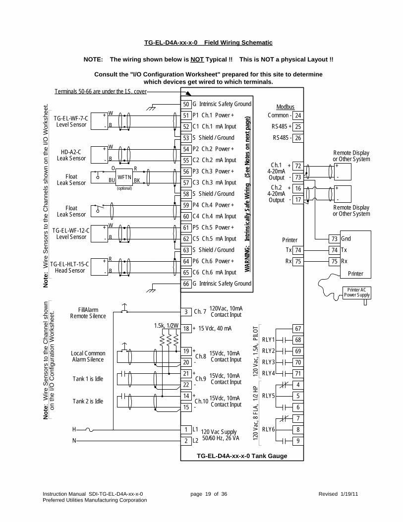
Instruction Manual SDI-TG-EL-D4A-xx-x-0 page 19 of 36 Revised 1/19/11 Preferred Utilities Manufacturing Corporation
51
52
53
54
55
56
57
58
59
60
61
62
63
64
65
66
3
19
20
21
22
14
15
1
2
72
73
74
75
16
17
24
25
26
67
69
70
71
4
5
6
7
8
68
9
RS485 +
RS485 -
Common -
Tx
Rx12
0 Va
c, 1
.5A,
PIL
OT
120
Vac,
8 F
LA,
1/2
HP
P1 Ch.1 Power +
G Intrinsic Safety Ground
C1 Ch.1 mA Input
50
S Shield / Ground
G Intrinsic Safety Ground
S Shield / Ground
S Shield / Ground
P2 Ch.2 Power +
C2 Ch.2 mA Input
P3 Ch.3 Power +
C3 Ch.3 mA Input
P4 Ch.4 Power +
C4 Ch.4 mA Input
P5 Ch.5 Power +
C5 Ch.5 mA Input
P6 Ch.6 Power +
C6 Ch.6 mA Input
120Vac, 10mA Contact Input
+
-
18 + 15 Vdc, 40 mA
L1
L2120 Vac Supply 50/60 Hz, 26 VA
Ch.8
+
-
+
-
Ch. 7
15Vdc, 10mA Contact Input
Ch.9
Ch.10
15Vdc, 10mA Contact Input
15Vdc, 10mA Contact Input
Ch.14-20mAOutput
+
-
+
-
Printer
Modbus
WA
RN
ING
: In
trin
sica
lly S
afe
Wiri
ng
(See
Not
es o
n ne
xt p
age)
RLY1
RLY2
RLY3
RLY4
RLY5
RLY6
TG-EL-D4A-xx-x-0 Field Wiring Schematic
H
N
73
74
75
Gnd
Tx
Rx
Printer
Printer ACPower Supply
TG-EL-D4A-xx-x-0 Tank Gauge
+
-Remote Displayor Other System
Remote Displayor Other System+
-
TG-EL-WF-7-CLevel Sensor
HD-A2-CLeak Sensor
Ch.24-20mAOutput
W
B
+
-
W
B
+
-R
BKWFTN
O
BU(optional)
FloatLeak Sensor
FloatLeak Sensor
TG-EL-WF-12-CLevel Sensor
TG-EL-HLT-15-CHead Sensor
W
B
+
-
R
B
+
-
No
te:
Wir
e S
enso
rs t
o th
e C
hann
els
show
n on
the
I/O
Wor
kshe
et.
FillAlarmRemote Silence
1.5k, 1/2W
Local CommonAlarm Silence
Tank 1 is Idle
Tank 2 is Idle
NOTE: The wiring shown below is NOT Typical !! This is NOT a physical Layout !!
Consult the "I/O Configuration Worksheet" prepared for this site to determinewhich devices get wired to which terminals.
No
te:
Wire
Sen
sors
to t
he C
hann
el s
how
non
the
I/O
Con
figur
atio
n W
orks
heet
.
Terminals 50-66 are under the I.S. cover
Instruction Manual SDI-TG-EL-D4A-xx-x-0 page 20 of 36 Revised 1/19/11 Preferred Utilities Manufacturing Corporation
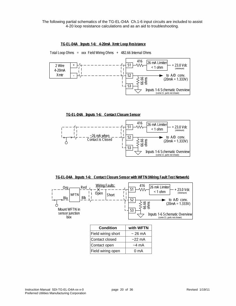
The following partial schematics of the TG-EL-D4A Ch.1-6 input circuits are included to assist 4-20 loop resistance calculations and as an aid to troubleshooting.
Condition with WFTN
Field wiring short ~ 26 mA
Contact closed ~22 mA
Contact open ~4 mA
Field wiring open 0 mA
TG-EL-D4A Inputs 1-6: 4-20mA Xmtr Loop Resistance
Total Loop Ohms = xxx Field Wiring Ohms + 482.66 Internal Ohms
51
52
53
416
66.6
6oh
ms
+ 23.0 Vdc(minimum)
to A/D conv.(20mA = 1.333V)
+
-
2 Wire4-20mA
Xmtr
Inputs 1-6 Schematic Overview(some I.S. parts not shown)
26 mA Limiter< 1 ohm
TG-EL-D4A Inputs 1-6: Contact Closure Sensor
51
52
53
416
66.6
6oh
ms
+ 23.0 Vdc(minimum)
to A/D conv.(20mA = 1.333V)
Inputs 1-6 Schematic Overview(some I.S. parts not shown)
26 mA Limiter< 1 ohm
~26 mA whenContact is Closed
TG-EL-D4A Inputs 1-6: Contact Closure Sensor with WFTN (Wiring Fault Test Network)
51
52
53
416
66.6
6oh
ms
+ 23.0 Vdc(minimum)
to A/D conv.(20mA = 1.333V)
Inputs 1-6 Schematic Overview(some I.S. parts not shown)
26 mA Limiter< 1 ohm
WFTN
Red
Blk
Org
Blu
Mount WFTN insensor junction
box
Wiring Faults:
Open Short

Instruction Manual SDI-TG-EL-D4A-xx-x-0 page 21 of 36 Revised 1/19/11 Preferred Utilities Manufacturing Corporation
Level Sensor Type Setup & "Stick Depth" The TG-EL-D4A accommodates three different methods to determine the fluid depth: ullage, depth, and head. This section discusses each method, the calibration data, and “depth adjust.” The SENSOR TYPE is configured via the menu path shown in the figure to the right. The SENSOR TYPE determines the measurement type and default calibration.
SENSOR TYPE Description Measurement
Type Default
20 mA Cal. Default
4 mA Cal. CM-LITER 20 mA Cal.
LVL WF7 Level sensor, 7 ft., TG-EL-WF-7-C Ullage 84.0 ullage 0.0 213.4 LVL WF12 Level sensor, 12 ft., TG-EL-WF-12-C Ullage 144.0 ullage 0.0 365.8 LVL UL18 Level sensor, 18 ft., TG-EL-UL-18-C Ullage 216.0 ullage 0.0 548.7
LVL OTHER Level sensor, other 4-20 mA Depth 100.0 depth 0.0 254.0 HEAD HL7 Head level sensor, 7 ft., TG-EL-HLT-7-C Head 80.0" of water n/a 203.2 cm WC HEAD HL15 Head level sensor, 15 ft.,TG-EL-HLT-15-C Head 160.0" of water n/a 406.4 cm WC
HEADOTHER Head level sensor, other 4-20 mA Head 100.0" of water n/a 254.0 cm WC When the SENSOR TYPE is changed, the calibration is changed automatically to the above defaults. The default calibration data for sensors LVL OTHER, HEADOTHER, and LVL UL18 must be changed by the user to reflect the calibration of the sensor being used. The calibration data for SENSOR TYPES: LVL WF7, LVL WF12, HEAD HL7, and HEAD HL15 should not be changed and must be set to the above default values. The default units are: IN-GALLON (inches-gallons). Units can be changed to CM-LITER (centimeters-liters) via the UNITS selection in CONFIGURE MENU. If CM-LITER units are used, the 20 mA calibration must be changed manually to the equivalent cm values in the table above via the INPUT X SENSOR CONFIG menu. Fluid depth methods Ullage is the distance from the top of the tank down to the top of the fluid. Actual depth = (tank full height – ullage) + depth adj. Depth is the distance from the top of the fluid down to the bottom of the tank. Actual depth = xmtr depth + depth adj. Head is the pressure at the bottom of the tank caused by the weight of the fluid above it. Head sensors measure this pressure in "Inches of Water Column" or in "Centimeters of Water Column" units. Actual depth = ("WC x Specific Gravity) + Depth Adj. The specific gravity is entered via the TANK x SIZING menu. (continued on next page)
TG-EL-WF-7-C
4-20mAUllageSignal:
Fluid Level
71.5"
Depth
Ullage
84" (7 ft)
0" Ullage4.00 mA
71.5" Ullage17.62 mA
84" Ullage20.00 mA
Vent
'Head' sensor inside tankmeasures:Inches of Water Column
PASSWORD
UNI TS
VOLUMESETPOI NTS
PRI NTERSETUP
I NPUTS &OUTPUTS
TANK 1SI ZI NGDATA
TANK 2SI ZI NGDATA
ALARMFUNCTI ONSENABLE/DI SABLE
DELI VERYSETUP
THEFTALARMSETUP
CONFI GURE MENU
SENSORI NPUTS
RELAYOUTPUTS
4- 20 MAOUTPUTS
I / OCONFI G
I NPUT 1I . S. AI N
I NPUT 2I . S. AI N
I NPUT 3I . S. AI N
I NPUT 4I . S. AI N
I NPUT 5I . S. AI N
I NPUT 6I . S. AI N
I NPUT 7120VACDI N
I NPUT 8DI N
I NPUT 9DI N
I NPUT 10DI N
I NPUTCONFI G
TANK
SENSORTYPE
SENSOROPTI ONS
DEPTHADJUSTI N/ CM
4MA CAL
20MA CAL
I NPUT xSENSORCONFI G
NOTE:These items
only appear forspecific sensor
types.
Instruction Manual SDI-TG-EL-D4A-xx-x-0 page 22 of 36 Revised 1/19/11 Preferred Utilities Manufacturing Corporation
Fluid depth methods (continued) Depth Adjust is provided to correct deviations caused by mounting height errors, sensor body sizes, … etc. Examples:
The TG-EL-HLT-7-C sensor body is 1" diameter. When it lies on the bottom of the tank, the pressure port is 0.5" above the bottom of the tank. Set Depth Adjust to +0.5" to compensate. If the TG-EL-WF-7-C tank mounting flange is the incorrect height, or if the float is in the wrong position on the wire, the Depth Adjust setting can be used to correct these errors.
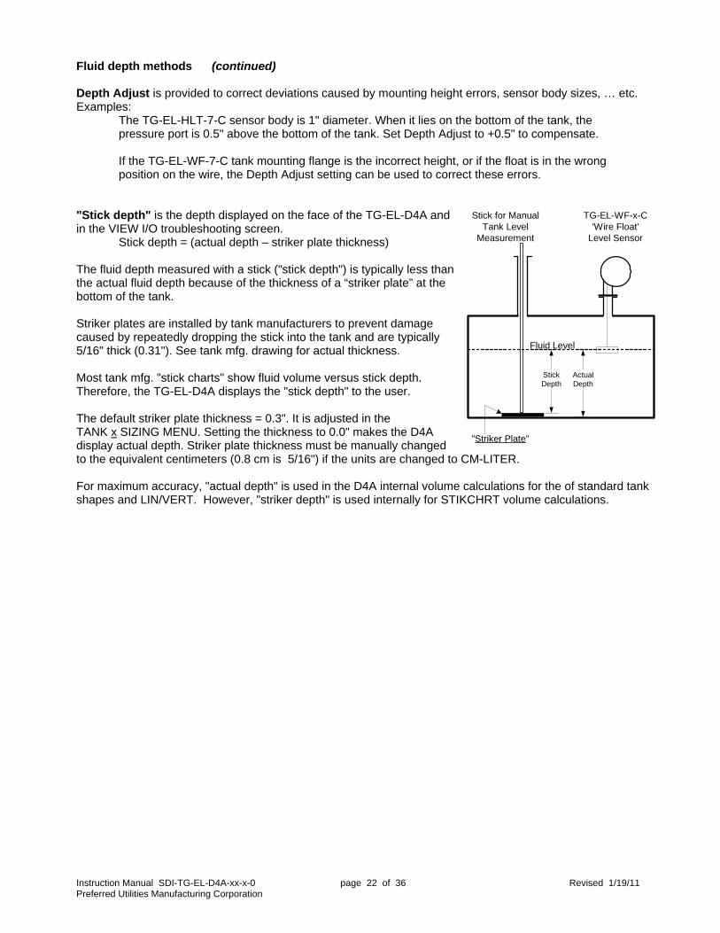
"Stick depth" is the depth displayed on the face of the TG-EL-D4A and in the VIEW I/O troubleshooting screen. Stick depth = (actual depth – striker plate thickness) The fluid depth measured with a stick ("stick depth") is typically less than the actual fluid depth because of the thickness of a “striker plate” at the bottom of the tank. Striker plates are installed by tank manufacturers to prevent damage caused by repeatedly dropping the stick into the tank and are typically 5/16" thick (0.31"). See tank mfg. drawing for actual thickness. Most tank mfg. "stick charts" show fluid volume versus stick depth. Therefore, the TG-EL-D4A displays the "stick depth" to the user. The default striker plate thickness = 0.3". It is adjusted in the TANK x SIZING MENU. Setting the thickness to 0.0" makes the D4A display actual depth. Striker plate thickness must be manually changed to the equivalent centimeters (0.8 cm is 5/16") if the units are changed to CM-LITER. For maximum accuracy, "actual depth" is used in the D4A internal volume calculations for the of standard tank shapes and LIN/VERT. However, "striker depth" is used internally for STIKCHRT volume calculations.
"Striker Plate"
TG-EL-WF-x-C'Wire Float'
Level Sensor
Stick for ManualTank Level
Measurement
Fluid Level
StickDepth
ActualDepth
Instruction Manual SDI-TG-EL-D4A-xx-x-0 page 23 of 36 Revised 1/19/11 Preferred Utilities Manufacturing Corporation
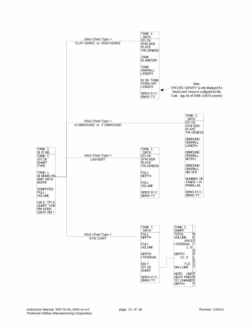
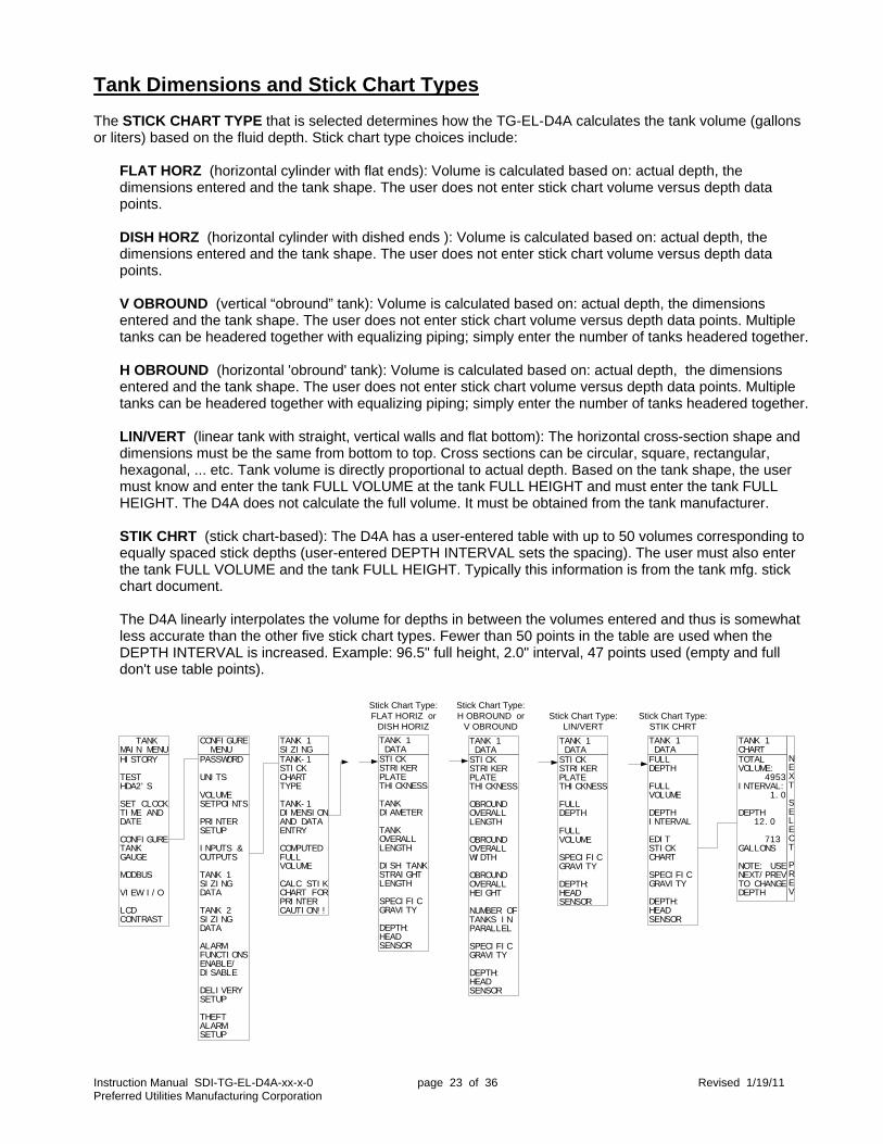
Tank Dimensions and Stick Chart Types The STICK CHART TYPE that is selected determines how the TG-EL-D4A calculates the tank volume (gallons or liters) based on the fluid depth. Stick chart type choices include:
FLAT HORZ (horizontal cylinder with flat ends): Volume is calculated based on: actual depth, the dimensions entered and the tank shape. The user does not enter stick chart volume versus depth data points. DISH HORZ (horizontal cylinder with dished ends ): Volume is calculated based on: actual depth, the dimensions entered and the tank shape. The user does not enter stick chart volume versus depth data points. V OBROUND (vertical “obround” tank): Volume is calculated based on: actual depth, the dimensions entered and the tank shape. The user does not enter stick chart volume versus depth data points. Multiple tanks can be headered together with equalizing piping; simply enter the number of tanks headered together. H OBROUND (horizontal 'obround' tank): Volume is calculated based on: actual depth, the dimensions entered and the tank shape. The user does not enter stick chart volume versus depth data points. Multiple tanks can be headered together with equalizing piping; simply enter the number of tanks headered together. LIN/VERT (linear tank with straight, vertical walls and flat bottom): The horizontal cross-section shape and dimensions must be the same from bottom to top. Cross sections can be circular, square, rectangular, hexagonal, ... etc. Tank volume is directly proportional to actual depth. Based on the tank shape, the user must know and enter the tank FULL VOLUME at the tank FULL HEIGHT and must enter the tank FULL HEIGHT. The D4A does not calculate the full volume. It must be obtained from the tank manufacturer. STIK CHRT (stick chart-based): The D4A has a user-entered table with up to 50 volumes corresponding to equally spaced stick depths (user-entered DEPTH INTERVAL sets the spacing). The user must also enter the tank FULL VOLUME and the tank FULL HEIGHT. Typically this information is from the tank mfg. stick chart document. The D4A linearly interpolates the volume for depths in between the volumes entered and thus is somewhat less accurate than the other five stick chart types. Fewer than 50 points in the table are used when the DEPTH INTERVAL is increased. Example: 96.5" full height, 2.0" interval, 47 points used (empty and full don't use table points).
TANK- 1STI CKCHARTTYPE
TANK- 1DI MENSI ONAND DATAENTRY
COMPUTEDFULLVOLUME
CALC STI KCHART FORPRI NTERCAUTI ON! !
TANK 1SI ZI NG
STI CKSTRI KERPLATETHI CKNESS
TANKDI AMETER
TANKOVERALLLENGTH
DI SH TANKSTRAI GHTLENGTH
SPECI FI CGRAVI TY
DEPTH:HEADSENSOR
TANK 1 DATA
STI CKSTRI KERPLATETHI CKNESS
OBROUNDOVERALLLENGTH
OBROUNDOVERALLWI DTH
OBROUNDOVERALLHEI GHT
NUMBER OFTANKS I NPARALLEL
SPECI FI CGRAVI TY
DEPTH:HEADSENSOR
TANK 1 DATA
STI CKSTRI KERPLATETHI CKNESS
FULLDEPTH
FULLVOLUME
SPECI FI CGRAVI TY
DEPTH:HEADSENSOR
TANK 1 DATA
Stick Chart Type:FLAT HORIZ or
DISH HORIZ
Stick Chart Type:H OBROUND or
V OBROUNDStick Chart Type:
LIN/VERTStick Chart Type:
STIK CHRT
PASSWORD
UNI TS
VOLUMESETPOI NTS
PRI NTERSETUP
I NPUTS &OUTPUTS
TANK 1SI ZI NGDATA
TANK 2SI ZI NGDATA
ALARMFUNCTI ONSENABLE/DI SABLE
DELI VERYSETUP
THEFTALARMSETUP
CONFI GURE MENU
HI STORY
TESTHDA2' S
SET CLOCKTI ME ANDDATE
CONFI GURETANKGAUGE
MODBUS
VI EW I / O
LCDCONTRAST
TANKMAI N MENU
NEXT
SELECT
PREV
FULLDEPTH
FULLVOLUME
DEPTHI NTERVAL
EDI TSTI CKCHART
SPECI FI CGRAVI TY
DEPTH:HEADSENSOR
TANK 1 DATA
TOTALVOLUME: 4953I NTERVAL: 1. 0
DEPTH 12. 0
713GALLONS
NOTE: USENEXT/ PREVTO CHANGEDEPTH
TANK 1CHART
Instruction Manual SDI-TG-EL-D4A-xx-x-0 page 24 of 36 Revised 1/19/11 Preferred Utilities Manufacturing Corporation
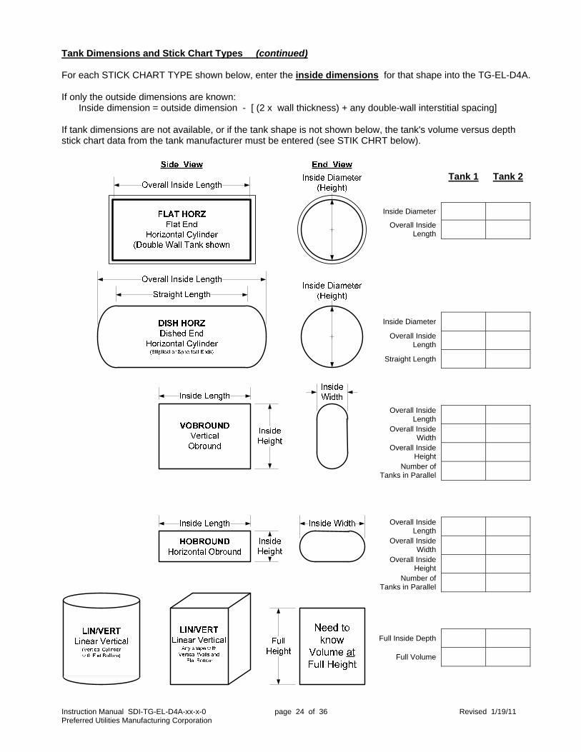
Tank Dimensions and Stick Chart Types (continued) For each STICK CHART TYPE shown below, enter the inside dimensions for that shape into the TG-EL-D4A. If only the outside dimensions are known: Inside dimension = outside dimension - [ (2 x wall thickness) + any double-wall interstitial spacing] If tank dimensions are not available, or if the tank shape is not shown below, the tank's volume versus depth stick chart data from the tank manufacturer must be entered (see STIK CHRT below).
Tank 1 Tank 2
Inside Diameter Overall Inside
Length
Inside Diameter
Overall Inside Length
Straight Length
Overall Inside Length
Overall Inside Width
Overall Inside Height
Number of Tanks in Parallel
Overall Inside Length
Overall Inside Width
Overall Inside Height
Number of Tanks in Parallel
Full Inside Depth
Full Volume

Instruction Manual SDI-TG-EL-D4A-xx-x-0 page 25 of 36 Revised 1/19/11 Preferred Utilities Manufacturing Corporation
Tank Dimensions and Stick Chart Types (continued) Head sensor specific gravity: If a HEAD HL7, HEAD HL15, or HEADOTHER sensor type is configured for this tank, then the specific gravity of the fluid must be entered in the TANK X DATA screens. Some specific gravities: Note: No. 6 fuel doesn't really have a “typical” value; it varies substantially based on the point of origin. The resulting stick depth derived from the HEAD sensor signal is displayed as the next item in the menu. If the displayed depth does not appear to be correct, verify the specific gravity, sensor 20 mA cal, depth adj., and striker-plate thickness entries, and check to make sure the sensor is at the bottom of the tank
Delivery Detection Setup The TG-EL-D4A calculates the delivery volume by: Delivered volume = delivery “stop” volume – “initial” volume While waiting for a delivery, the D4A monitors tank volume and saves the lowest volume as the “initial” volume. To prevent false delivery detection, The D4A will declare only that a delivery is "in progress” if the volume has increased more than the user-adjusted START DELIVERY: VOLUME INCREASE value. The VOLUME INCREASE value should be set high enough to prevent false delivery detection due to fluid thermal expansion, but lower than the smallest delivery volume anticipated. The default value is 100 gallons. The delivery is considered completed when the volume has not increased for SETTLING SECONDS (user-adjustable). This time delay should be long enough to allow the driver to drain the hose into the tank after stopping the delivery. The default time is 60 seconds. NOTE: If the fuel from the tank is being burned/used while the delivery is in progress, the TG-EL-D4A will report a smaller delivery volume than actual delivery volume.
Delivery Verification Setup Delivery verification requires two sensors per tank, configured as primary and secondary via the INPUT CONFIG menu. The allowed combinations are: Level/Flow, Head/Flow, and Level/Head. After each delivery, the D4A compares the delivery volume reported by each sensor. If the difference between the two delivery volumes is larger than the user-adjusted GAL/LITER 2-SENSOR VERIFICATION ALARM, the difference is noted on the printed delivery report and also stored in the alarm history, but it does not actually trigger the alarm system. If a level/head sensor combination is installed: After a delivery, if the D4A determines that the measured before/after specific gravity has changed more than the user-entered SP.GRAV. CHANGE THRESHOLD, the difference is noted on the printed delivery report and also stored in the alarm history, but it does not actually trigger the alarm system.
Fluid Typical Range No. 1 fuel oil or kerosene 0.82 0.806 – 0.825 No. 2 fuel oil or diesel 0.876 0.825 – 0.887 No. 6 fuel oil 1.014 0.950 – 1.050
HI STORY
TESTHDA2' S
SET CLOCKTI ME ANDDATE
CONFI GURETANKGAUGE
MODBUS
VI EW I / O
LCDCONTRAST
TANKMAI N MENU
PASSWORD
UNI TS
VOLUMESETPOI NTS
PRI NTERSETUP
I NPUTS &OUTPUTS
TANK 1SI ZI NGDATA
TANK 2SI ZI NGDATA
ALARMFUNCTI ONSENABLE/DI SABLE
DELI VERYSETUP
THEFTALARMSETUP
CONFI GURE MENU
STARTDELI VERY:VOLUMEI NCREASE
STOPDELI VERY:SETTLI NGSECONDS
GAL/ LI TER2- SENSORVERI FI CATI ON ALARM
SP. GRAV.CHANGEALARMTHRESHOLD
DELI VERYSETUP
Instruction Manual SDI-TG-EL-D4A-xx-x-0 page 26 of 36 Revised 1/19/11 Preferred Utilities Manufacturing Corporation
HI GH- HI GHALARMTANK 1
HI GHALARMTANK 1
LOWALARMTANK 1
LOW- LOWALARMTANK 1
HI GH- HI GHALARMTANK 2
HI GHALARMTANK 2
LOWALARMTANK 2
LOW- LOWALARMTANK 2
ALARMCONFI G
HI STORY
TESTHDA2' S
SET CLOCKTI ME ANDDATE
CONFI GURETANKGAUGE
MODBUS
VI EW I / O
LCDCONTRAST
TANKMAI N MENU
PASSWORD
UNI TS
VOLUMESETPOI NTS
PRI NTERSETUP
I NPUTS &OUTPUTS
TANK 1SI ZI NGDATA
TANK 2SI ZI NGDATA
ALARMFUNCTI ONSENABLE/DI SABLE
DELI VERYSETUP
THEFTALARMSETUP
CONFI GURE MENU
HI GH- HI GHTANK 1
HI GHTANK 1
LOWTANK 1
LOW- LOWTANK 1
HI GH- HI GHTANK 2
HI GHTANK 2
LOWTANK 2
LOW- LOWTANK 2
ALARMDELAYSECONDS
FI LLALMAUTOSI LENCESECONDS
VOLUMESETPOI NTS
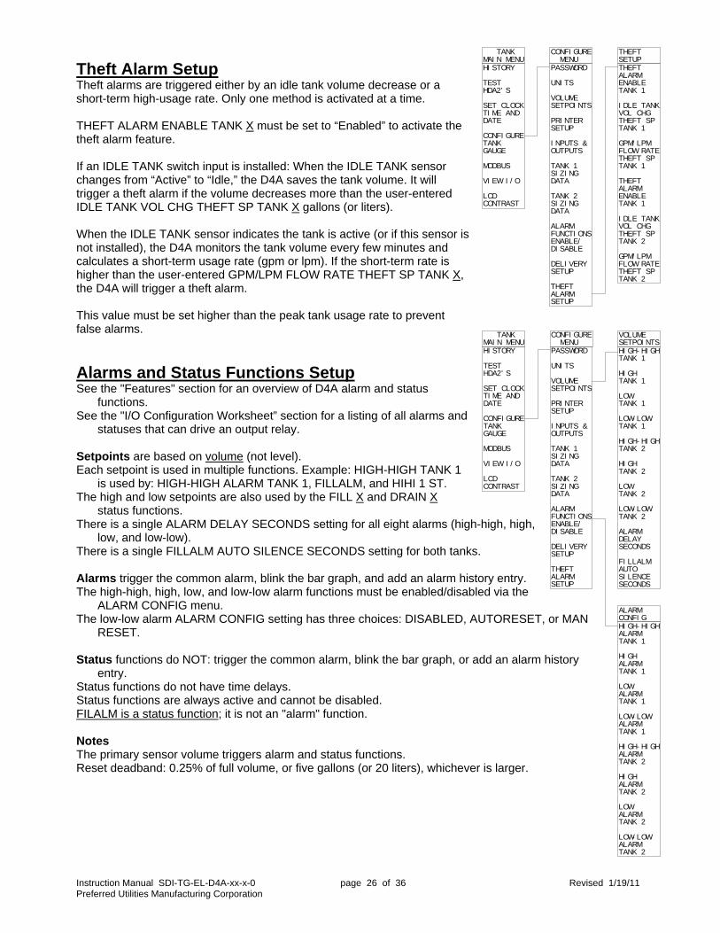
Theft Alarm Setup Theft alarms are triggered either by an idle tank volume decrease or a short-term high-usage rate. Only one method is activated at a time. THEFT ALARM ENABLE TANK X must be set to “Enabled” to activate the theft alarm feature. If an IDLE TANK switch input is installed: When the IDLE TANK sensor changes from “Active” to “Idle,” the D4A saves the tank volume. It will trigger a theft alarm if the volume decreases more than the user-entered IDLE TANK VOL CHG THEFT SP TANK X gallons (or liters). When the IDLE TANK sensor indicates the tank is active (or if this sensor is not installed), the D4A monitors the tank volume every few minutes and calculates a short-term usage rate (gpm or lpm). If the short-term rate is higher than the user-entered GPM/LPM FLOW RATE THEFT SP TANK X, the D4A will trigger a theft alarm. This value must be set higher than the peak tank usage rate to prevent false alarms.
Alarms and Status Functions Setup See the "Features" section for an overview of D4A alarm and status
functions. See the "I/O Configuration Worksheet” section for a listing of all alarms and
statuses that can drive an output relay. Setpoints are based on volume (not level). Each setpoint is used in multiple functions. Example: HIGH-HIGH TANK 1
is used by: HIGH-HIGH ALARM TANK 1, FILLALM, and HIHI 1 ST. The high and low setpoints are also used by the FILL X and DRAIN X
status functions. There is a single ALARM DELAY SECONDS setting for all eight alarms (high-high, high,
low, and low-low). There is a single FILLALM AUTO SILENCE SECONDS setting for both tanks. Alarms trigger the common alarm, blink the bar graph, and add an alarm history entry. The high-high, high, low, and low-low alarm functions must be enabled/disabled via the
ALARM CONFIG menu. The low-low alarm ALARM CONFIG setting has three choices: DISABLED, AUTORESET, or MAN
RESET. Status functions do NOT: trigger the common alarm, blink the bar graph, or add an alarm history
entry. Status functions do not have time delays. Status functions are always active and cannot be disabled. FILALM is a status function; it is not an "alarm" function. Notes The primary sensor volume triggers alarm and status functions. Reset deadband: 0.25% of full volume, or five gallons (or 20 liters), whichever is larger.
THEFTALARMENABLETANK 1
I DLE TANKVOL CHGTHEFT SPTANK 1
GPM/ LPMFLOW RATETHEFT SPTANK 1
THEFTALARMENABLETANK 1
I DLE TANKVOL CHGTHEFT SPTANK 2
GPM/ LPMFLOW RATETHEFT SPTANK 2
THEFTSETUP
HI STORY
TESTHDA2' S
SET CLOCKTI ME ANDDATE
CONFI GURETANKGAUGE
MODBUS
VI EW I / O
LCDCONTRAST
TANKMAI N MENU
PASSWORD
UNI TS
VOLUMESETPOI NTS
PRI NTERSETUP
I NPUTS &OUTPUTS
TANK 1SI ZI NGDATA
TANK 2SI ZI NGDATA
ALARMFUNCTI ONSENABLE/DI SABLE
DELI VERYSETUP
THEFTALARMSETUP
CONFI GURE MENU

Instruction Manual SDI-TG-EL-D4A-xx-x-0 page 27 of 36 Revised 1/19/11 Preferred Utilities Manufacturing Corporation
Printer See the "Features" section for the description of the short and long Reports. Reports print 8-10 seconds after pressing the button on the main screen. The PRINTER SETUP menu determines when the printer should automatically print, and which report. The choices are:
When Report options At midnight NO, SHORT RPT, or LONG RPT
After a delivery NO or SHORT RPT After any alarm NO or SHORT RPT Sunday Weekly NO or LONG RPT
The LOCATION NUMBER (0 – 32767) simply prints on the reports. It helps to identify the building/location where the report was generated.
Troubleshooting & VIEW I/O Main menu item VIEW I/O displays the current values for all inputs, relay outputs and both 4-20 mA outputs. Input channels 1-6 display the mA value as well as the signal in scaled engineering units. This allows you to verify electrical operation as well as configuration setup for each input. Note: Level sensor inputs display the resulting "stick depth" based on the following: WF/UL ullage: stick depth = tank full height – xmtr ullage + depth adj. – striker Depth xmtr: stick depth = xmtr depth + depth adj. – striker Head xmtr: stick depth = ("WC x sp. gravity) + depth adj. – striker Channel 1-6 HD-A2 leak sensor displayed values:
Display Condition Signal levels
SHORT Field wiring shorted > 21.5 mA
TEST HD-A2 power-up test 18.5 to 21.5 mA
DRY Dry 15.5 to 18.5 mA
WATER Water detected 12.5 to 15.5 mA
OIL Oil detected 1.5 to 12.5 mA
OPEN Field wiring open < 1.5 mA Channel 1-6 contact closure sensor displayed values:
Channel 7-10 contact closure sensor displayed values:
Display Condition with WFTN without WFTN
SHORT Field wiring short > 23.5 mA > 8 mA
ACTIVE N.C. contact open 1.5 to 8 mA < 8 mA
INACTIVE N.C. contact closed 8 to 23.5 mA > 8 mA
ACTIVE N.O. contact closed 8 to 23.5 mA > 8 mA
INACTIVE N.O. contact open 1.5 to 8 mA < 8 mA
OPEN Field wiring open < 1.5 mA < 8 mA
Display Condition
ACTIVE N.C. contact open
ACTIVE N.C. contact open
ACTIVE N.O. contact closed
INACTIVE N.O. contact open
PRI NTERSETUP
HI STORY
TESTHDA2' S
SET CLOCKTI ME ANDDATE
CONFI GURETANKGAUGE
MODBUS
VI EW I / O
LCDCONTRAST
TANKMAI N MENU
PASSWORD
UNI TS
VOLUMESETPOI NTS
PRI NTERSETUP
I NPUTS &OUTPUTS
TANK 1SI ZI NGDATA
TANK 2SI ZI NGDATA
ALARMFUNCTI ONSENABLE/DI SABLE
DELI VERYSETUP
THEFTALARMSETUP
CONFI GURE MENU
PRI NTATMI DNI GHT
PRI NTAFTERDELI VERY
PRI NTAFTER ANYALARM
PRI NTSUNDAYWEEKLYREPORT
LOCATI ONNUMBER

Instruction Manual SDI-TG-EL-D4A-xx-x-0 page 28 of 36 Revised 1/19/11 Preferred Utilities Manufacturing Corporation
Password The TG-EL-D4A has an optional password system. Passwords are disabled when the TG-EL-D4A is shipped. Contact your installer to obtain the code required to activate the password system. When the password system is activated and the D4A is logged out:
Reports can be printed. The main display tank can be selected. Alarms can be silenced. All submenus and menu items can be displayed. The clock can be set. An HD-A2 test can be started. No other items can be changed within the menu system.
When a password is entered, it automatically logs out after one hour. After entering the code to activate the password system, use the PASSWORDS menu to change the password to any value between –32767 and +32767. Keep a copy of the new password in a secure location. If the new password is lost or forgotten, contact your sales representative or Preferred Utilities Fuel Oil Systems Technical Support to obtain a one-day temporary password. You must be near the TG-EL-D4A and provide various pieces of data from the menu displays when requesting a temporary password.

Instruction Manual SDI-TG-EL-D4A-xx-x-0 page 29 of 36 Revised 1/19/11 Preferred Utilities Manufacturing Corporation
Modbus Field selectable via the MODBUS menu: Protocol: RTU or ASCII Address: 1-247 Baud: 1200, 4800, 9600, 19200, 38400 Parity: Odd, Even, None (“None” requires two stop bits.) Commands: 01 read coils, 03 read holding registers, 05 write single coil, 06 write single holding register (A maximum of 10 registers can be read in a single poll.)
TG-EL-D4A Fuel Sentry Tank Gauge Modbus Data Registers Tank 1 Tank 2 Common Format Current Volume 40500 40505 1 Volume multiplier 40501 40506 2 Current Depth 40502 40507 3 Volume at Midnight 40504 40509 1 Alarm & Status bits 40510 40512 40514 8, 9 Tank 1 Tank 2 Format Usage, Day 1 (yesterday) 40515 40522 1 Usage, Day 2 40516 40523 1 Usage, Day 3 40517 40524 1 Usage, Day 4 40518 40525 1 Usage, Day 5 40519 40526 1 Usage, Day 6 40520 40527 1 Usage, Day 7 40521 40528 1 Usage, Day 8 40522 n/a 1 Usage, Day 9 40523 n/a 1 Usage, Day 10 40524 n/a 1 Usage, Day 11 40525 n/a 1 Usage, Day 12 40526 n/a 1 Usage, Day 13 40527 n/a 1 Usage, Day 14 (14 days ago) 40528 n/a 1
Usage, week 1 (ending last Sunday night) 40529 40537 3 Usage, week 2 40531 40539 3 Usage, week 3 40533 40541 3 Usage, week 4 40535 40543 3 Usage, week 5 40537 n/a 3 Usage, week 6 40539 n/a 3 Usage, week 7 40541 n/a 3 Usage, week 8 (ending 8 Sunday's ago) 40543 n/a 3
Usage "Day 1" Date Year 40809 10 Month / Day 40810 11
Instruction Manual SDI-TG-EL-D4A-xx-x-0 page 30 of 36 Revised 1/19/11 Preferred Utilities Manufacturing Corporation
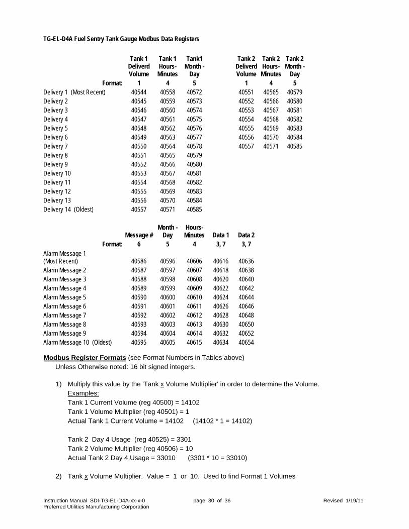
TG-EL-D4A Fuel Sentry Tank Gauge Modbus Data Registers
Tank 1 Deliverd Volume
Tank 1 Hours- Minutes
Tank1 Month -
Day
Tank 2 Deliverd Volume
Tank 2 Hours- Minutes
Tank 2 Month -
Day Format: 1 4 5 1 4 5
Delivery 1 (Most Recent) 40544 40558 40572 40551 40565 40579 Delivery 2 40545 40559 40573 40552 40566 40580 Delivery 3 40546 40560 40574 40553 40567 40581 Delivery 4 40547 40561 40575 40554 40568 40582 Delivery 5 40548 40562 40576 40555 40569 40583 Delivery 6 40549 40563 40577 40556 40570 40584 Delivery 7 40550 40564 40578 40557 40571 40585 Delivery 8 40551 40565 40579 Delivery 9 40552 40566 40580 Delivery 10 40553 40567 40581 Delivery 11 40554 40568 40582 Delivery 12 40555 40569 40583 Delivery 13 40556 40570 40584 Delivery 14 (Oldest) 40557 40571 40585
Message # Month -
Day Hours- Minutes Data 1 Data 2
Format: 6 5 4 3, 7 3, 7 Alarm Message 1 (Most Recent) 40586 40596 40606 40616 40636 Alarm Message 2 40587 40597 40607 40618 40638 Alarm Message 3 40588 40598 40608 40620 40640 Alarm Message 4 40589 40599 40609 40622 40642 Alarm Message 5 40590 40600 40610 40624 40644 Alarm Message 6 40591 40601 40611 40626 40646 Alarm Message 7 40592 40602 40612 40628 40648 Alarm Message 8 40593 40603 40613 40630 40650 Alarm Message 9 40594 40604 40614 40632 40652 Alarm Message 10 (Oldest) 40595 40605 40615 40634 40654 Modbus Register Formats (see Format Numbers in Tables above) Unless Otherwise noted: 16 bit signed integers.
1) Multiply this value by the 'Tank x Volume Multiplier' in order to determine the Volume. Examples: Tank 1 Current Volume (reg 40500) = 14102 Tank 1 Volume Multiplier (reg 40501) = 1 Actual Tank 1 Current Volume = 14102 (14102 * 1 = 14102) Tank 2 Day 4 Usage (reg 40525) = 3301 Tank 2 Volume Multiplier (reg 40506) = 10 Actual Tank 2 Day 4 Usage = 33010 (3301 * 10 = 33010)
2) Tank x Volume Multiplier. Value = 1 or 10. Used to find Format 1 Volumes

Instruction Manual SDI-TG-EL-D4A-xx-x-0 page 31 of 36 Revised 1/19/11 Preferred Utilities Manufacturing Corporation
Modbus Register Formats (continued) 3) Double Register, 32 bit signed Integer.
The lower register is the Most Significant Word. The higher Register is the Least Significant Word. Example: Tank 1 Week 1 Usage, reg 40529 = 1, reg 40530 = 1723 Usage = 67259 = ( 1 * 65536 ) + 1723
4) Packed Hours/Minutes for Deliveries and Alarm History. Most Significant Byte = Hours, Least Significant Byte = Minutes. Example: Tank 1 Delivery Hours/Minutes, reg 40558 = 3351 = 0d17H Hours = 0dH = 13, Minutes = 017H = 23; Time = 13:23 or 1:23 PM
5) Packed Month / Day for Deliveries and Alarm History. Most Significant Byte = Month, Least Significant Byte = Day. Example: Tank 1 Delivery Month/Day, reg 40572 = 2072 = 0818H Month = 08H = 8, Day = 018H = 24; Date = 8/24 = August 24th
6) Alarm Message Codes:
Code Message Data 1 Data 1 64 Tank 1 High-High Alarm 65 Tank 1 High Alarm 66 Tank 1 Low Alarm 67 Tank 1 Low-Low Alarm 68 Tank 1 Theft Alarm Initial Volume..or..Consumption Rate 69 Tank 1 Leak Alarm Channel Status (see Format 7) 70 Tank 1 FilAlm LS Open or Short 71 Tank 1 Lk HD-A2 Test Failed Channel 78 Tank 1 Pri & Sec Delivery Vol Difference Primary sensor delivery volume Secondary sensor delivery volume 79 Tank 1 Delivery Changed Specific Gravity Sp gravity before delivery (Format 7) Sp gravity after delivery (Format 7) 80 Tank 1 Delivery Level and Flow Total Differ Primary sensor delivery volume Flow meter delivery volume 128 Tank 2 High-High Alarm 129 Tank 2 High Alarm 130 Tank 2 Low Alarm 131 Tank 2 Low-Low Alarm 132 Tank 2 Theft Alarm Initial Volume..or..Consumption Rate 133 Tank 2 Leak Alarm Channel Status (see Format 7) 134 Tank 2 FilAlm LS Open or Short 135 Tank 2 Lk HD-A2 Test Failed Channel 142 Tank 2 Pri & Sec Delivery Vol Difference Primary sensor delivery volume Secondary sensor delivery volume 143 Tank 2 Delivery Change Specific Gravity Sp gravity before delivery (Format 7) Sp gravity after delivery (Format 7) 144 Tank 2 Delivery Level and Flow Total Differ Primary sensor delivery volume Flow meter delivery volume 192 Common Leak Alarm Channel Status (see Format 7) 193 Common LK HD-A2 Test Failed Channel
7) Data1 and Data2 Format Notes.
For Codes 69, 133, 192; Leak Sensor Status Codes: 0=Inactive, 1=Active, 2=Field Wiring Open, 3=Field Wiring Short, 4=Oil, 5=Water, 6=Dry, 7=Test, 8= Sensor Configuration Error. For Codes 79, 143: The Modbus value is: (Specific Gravity x 1000)
Instruction Manual SDI-TG-EL-D4A-xx-x-0 page 32 of 36 Revised 1/19/11 Preferred Utilities Manufacturing Corporation
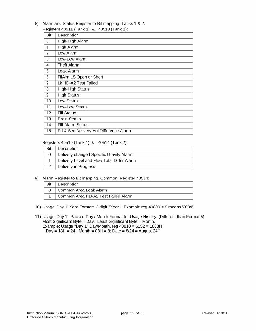
8) Alarm and Status Register to Bit mapping, Tanks 1 & 2: Registers 40511 (Tank 1) & 40513 (Tank 2):
Bit Description
0 High-High Alarm
1 High Alarm
2 Low Alarm
3 Low-Low Alarm
4 Theft Alarm
5 Leak Alarm
6 FilAlm LS Open or Short
7 Lk HD-A2 Test Failed
8 High-High Status
9 High Status
10 Low Status
11 Low-Low Status
12 Fill Status
13 Drain Status
14 Fill-Alarm Status
15 Pri & Sec Delivery Vol Difference Alarm
Registers 40510 (Tank 1) & 40514 (Tank 2):
Bit Description
0 Delivery changed Specific Gravity Alarm
1 Delivery Level and Flow Total Differ Alarm
2 Delivery in Progress
9) Alarm Register to Bit mapping, Common, Register 40514:
Bit Description
0 Common Area Leak Alarm
1 Common Area HD-A2 Test Failed Alarm
10) Usage 'Day 1' Year Format: 2 digit "Year". Example reg 40809 = 9 means '2009'
11) Usage 'Day 1' Packed Day / Month Format for Usage History. (Different than Format 5)
Most Significant Byte = Day, Least Significant Byte = Month. Example: Usage "Day 1" Day/Month, reg 40810 = 6152 = 1808H Day = 18H = 24, Month = 08H = 8; Date = 8/24 = August 24th

Instruction Manual SDI-TG-EL-D4A-xx-x-0 page 33 of 36 Revised 1/19/11 Preferred Utilities Manufacturing Corporation
TG-EL-D4A Fuel Sentry Tank Gauge Configuration Record
Location: Main Menu > Configure Tank Gauge > Volume Setpoints see pages: 4, 5, 26
High-High Tank 1 (also FillAlarm Setpoint, typically 90% full)
High Tank 1
Low Tank 1
Low-Low Tank 1
High-High Tank 2 (also FillAlarm Setpoint, typically 90% full)
High Tank 2
Low Tank 2
Low-Low Tank 2
Alarm Delay Seconds
FillAlm Auto Silence Seconds Main Menu > Configure Tank Gauge > Printer Setup
see pages: 27
Print At Midnight NO, SHORT RPT, LONG RPT
Print After Delivery NO, SHORT RPT
Print After Any Alarm NO, SHORT RPT
Print Sunday Weekly Report NO, LONG RPT
Location Number 0 - 32767 Main Menu > Configure Tank Gauge > Inputs & Outputs > Sensor Inputs > Input 1 - 6 see pages: 12-14, 21-22
Tank Sensor Type Sensor Options Depth Adjust 4mA Cal 20mA Cal
Input 1
Input 2
Input 3
Input 4
Input 5
Input 6
Primary, Secondary, N.C.+ WFTN, N.O.+WFTN, N.C., N.O.
LVL WF7, LVL WF12, LVL UL18, LVL OTHER, HEAD HL7, HEAD HL15, HEADOTHER, FLOW, LK HD-A2, LK CONTAC, FILALM LS, FILALM AS
Disabled, Tank 1, Tank 2, Common

Instruction Manual SDI-TG-EL-D4A-xx-x-0 page 34 of 36 Revised 1/19/11 Preferred Utilities Manufacturing Corporation
Main Menu > Configure Tank Gauge > Inputs & Outputs > Sensor Inputs > Input 7 - 10 see pages: 12-14
Tank Sensor Type Sensor Options
Input 7
Input 8
Input 9
Input 10
Primary, Secondary, N.C.+ WFTN, N.O.+WFTN, N.C., N.O. FILALM AS, IDLE TANK, COMMON AS Disabled, Tank 1, Tank 2, Common Main Menu > Configure Tank Gauge > Inputs & Outputs > Relay Outputs > Relay 1 - 6
see pages: 12-14, 26
Relay 1 ALARM COM, LEAK COM, LEAK x,
Relay 2 LEAK OTHR, FILLALMx, THEFT x,
Relay 3 HIHI x AL, HI x AL, LO x AL, LOLO x AL,
Relay 4 HIHI x ST, HI X ST, LO x ST, Relay 5 LOLO x ST, FILL x, DRAIN x Relay 6 Main Menu > Configure Tank Gauge > Inputs & Outputs > 4-20 mA Outputs > Outputs 1 - 2
see pages: 12-14
Output 1 T1 VOL, T1 LVL, T2 VOL, T2 LVL
Output 2 T1 VOL, T1 LVL, T2 VOL, T2 LVL Main Menu > Configure Tank Gauge > Tank 1 Sizing Data
see pages: 23
Stick Chart Type FLAT HORZ, DISH HORZ, H OBROUND, V
OBROUND, LIN/VERT, STIK CHRT
Computed Full Volume Main Menu > Configure Tank Gauge > Tank 1 Sizing Data > Tank 1 Dimension and Data Entry
see pages: 21-22, 24-25
Stick Striker Plate Thickness
Tank Dimensions see page 24
Specific Gravity
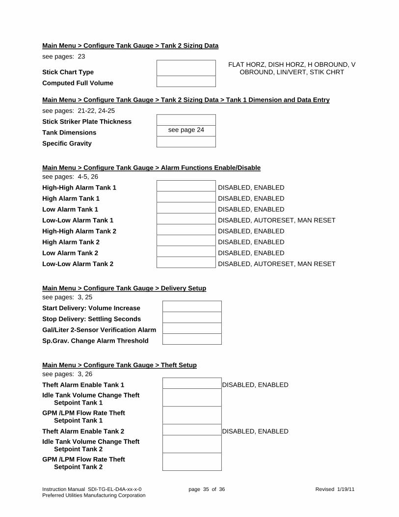
Instruction Manual SDI-TG-EL-D4A-xx-x-0 page 35 of 36 Revised 1/19/11 Preferred Utilities Manufacturing Corporation
Main Menu > Configure Tank Gauge > Tank 2 Sizing Data
see pages: 23
Stick Chart Type FLAT HORZ, DISH HORZ, H OBROUND, V
OBROUND, LIN/VERT, STIK CHRT
Computed Full Volume Main Menu > Configure Tank Gauge > Tank 2 Sizing Data > Tank 1 Dimension and Data Entry
see pages: 21-22, 24-25
Stick Striker Plate Thickness
Tank Dimensions see page 24
Specific Gravity Main Menu > Configure Tank Gauge > Alarm Functions Enable/Disable see pages: 4-5, 26
High-High Alarm Tank 1 DISABLED, ENABLED
High Alarm Tank 1 DISABLED, ENABLED
Low Alarm Tank 1 DISABLED, ENABLED
Low-Low Alarm Tank 1 DISABLED, AUTORESET, MAN RESET
High-High Alarm Tank 2 DISABLED, ENABLED
High Alarm Tank 2 DISABLED, ENABLED
Low Alarm Tank 2 DISABLED, ENABLED
Low-Low Alarm Tank 2 DISABLED, AUTORESET, MAN RESET Main Menu > Configure Tank Gauge > Delivery Setup see pages: 3, 25
Start Delivery: Volume Increase
Stop Delivery: Settling Seconds
Gal/Liter 2-Sensor Verification Alarm
Sp.Grav. Change Alarm Threshold Main Menu > Configure Tank Gauge > Theft Setup see pages: 3, 26
Theft Alarm Enable Tank 1 DISABLED, ENABLED
Idle Tank Volume Change Theft Setpoint Tank 1
GPM /LPM Flow Rate Theft Setpoint Tank 1
Theft Alarm Enable Tank 2 DISABLED, ENABLED
Idle Tank Volume Change Theft Setpoint Tank 2
GPM /LPM Flow Rate Theft Setpoint Tank 2
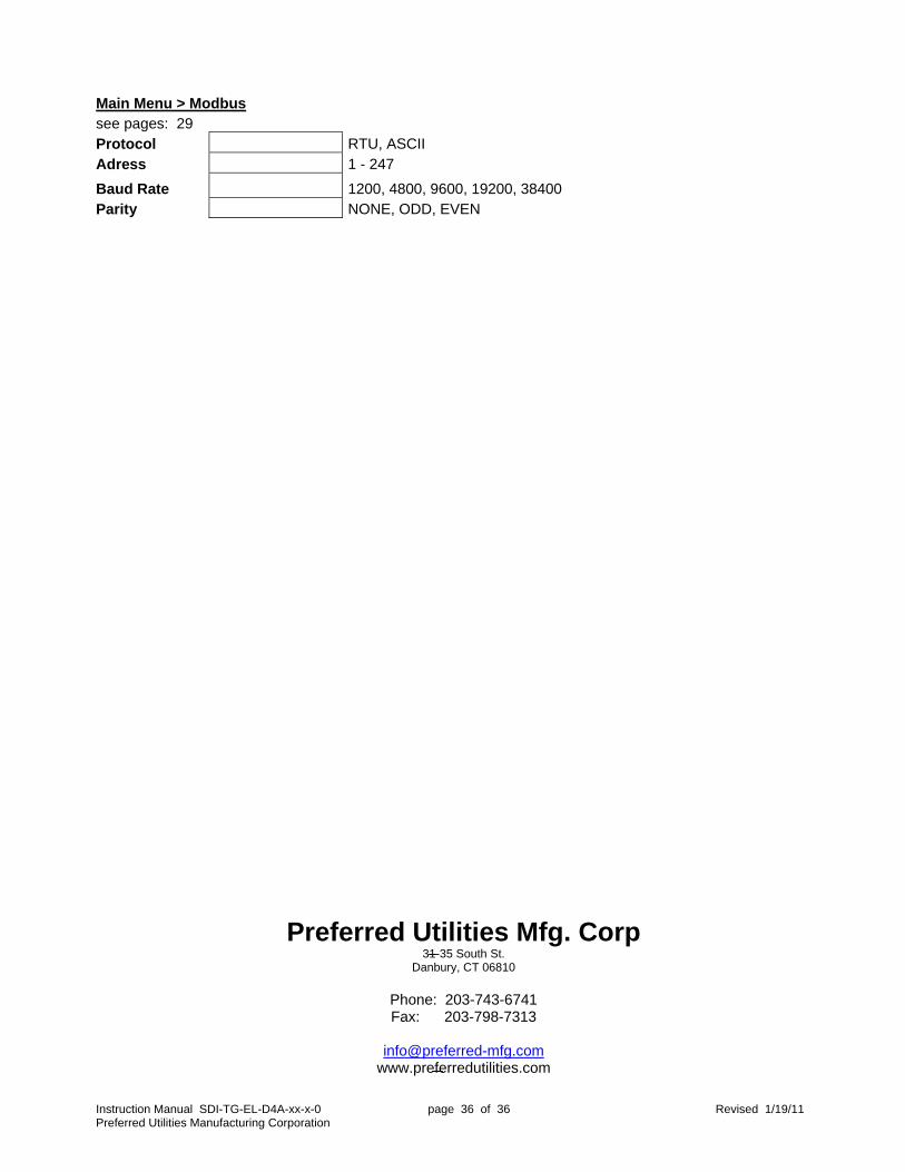
Instruction Manual SDI-TG-EL-D4A-xx-x-0 page 36 of 36 Revised 1/19/11 Preferred Utilities Manufacturing Corporation
Main Menu > Modbus see pages: 29 Protocol RTU, ASCII Adress 1 - 247
Baud Rate 1200, 4800, 9600, 19200, 38400 Parity NONE, ODD, EVEN
Preferred Utilities Mfg. Corp 31-35 South St.
Danbury, CT 06810
Phone: 203-743-6741 Fax: 203-798-7313
www.preferredutilities.com