Embed Size (px)
Citation preview

Fuel oil System
STC / SBC

Fuel oil System -- Purpose
Pressurizing of Fuel oil to required level by FPM
Ensure continuous supply of fuel to all Fuel Injection Pumps
Supply of Fuel to Injectors by Fuel Injection Pump at a higher pressure
Supply of required quantity of fuel at required pressure to combustion chamber

Components in Fuel oil SystemFuel oil tankFuel trapPrimary Filter & Secondary FilterFuel booster pumpRelief ValveRegulating valveFuel main header(Right & Left)Fuel injection pumps( 8 + 8 )Fuel injectors( 8 + 8 )High pressure pipeline (8 + 8)Crossover pipe( @ power takeoff end)

6000 litres in WDG 3A and WDM 3D.(Fabricated Bogie Locos)
5000 litres in WDM 2 and WDM 3A(Tri Mount Bogie Locos)
Fuel Tank Capacity&
Minimum Fuel Oil Balance:
1000 litres + Trip ration for working the train + 10% of the Trip ration [or as per Stencil in Loco]

FUEL OIL TANK
Steel fabricated tank located between the two trucks
Provision of fuel oil filling on both side with caps & strainers, to prevent foreign particles entering into the tank.
Glow rod gauge & scale are provided on both sides
Vent pipe is provided to Maintain air pressure on the top surface of oilEnable air to escape out during filling
Fuel trapProvided on the right side of the engine block between fuel tank and fuel primary filter. Traps heavy particles in fuel such as paper, cloth etc.
Primary & Secondary filtersPrimary filter located at Engine right Side free End (WDM 2, WDM 3A), Engine room or Compressor Room(WDG3A). Secondary filter is located at Engine right side free end.Filters minute particles.

Fuel booster pumpElectrical Motor driven pump is located at the Compressor room.
When the pump starts working a partial vacuum is created in the pump and the fuel oil is sucked from the tank.

Fuel oil pressure Relief & Regulating valves
Relief valve is located near Secondary filter at engine right side free end & set at 5.5 Kg/sq. cm2.
Relief valve is provided to protect the pump and motor from over load whenever the secondary filter is choked or due to any blockage in the system.
Regulating valve is located at engine left side free end & set at 4.4 kg/cm2.Regulating valve maintains constant pressure in the fuel main headers. The excess pressure returns to the tank

Fuel main headersThe header runs from free end to the power take off end on both sides.
These headers have fuel oil always stored at certain pressure.
Cross over pipe connects both side fuel oil main headers at power take off end
Fuel reaches the FIP’s through fuel jumper pipe/ Banjo pipe

High pressure pipe line
It is connected between FIPs & Injectors
The pressure of fuel oil flowing will be very high (approx 7000 PSI to 9000 PSI).

Fuel injection pumps - FIPsFIPs are operated by centre cams of the camshaft
FIPs supply Fuel at very high pressure to the injectors.
FIPs are provided with fuel rack to allow required quantity of fuel.
Fuel injectorsFinely drilled spray holes at the tip of the injectorsprays fuel in atomized form so as to distribute the oilthroughout the combustion chamber.
The pressure during fuel injection is around 3600 PSI to 4050 PSI.


AC – DC locos

Reason RemediesWeak Battery Contact PRC
BS not closed CloseMB1 / MB2 - OFF / tripped Switch ON / resetMFPB1 / MFPB2 - OFF / tripped Switch ON / resetFPC not picking up§Terminals disconnected / Slack§Coil short circuited or burnt
§Any mechanical binding
§Connect them§Remove wire No. 13 & insulate it. Pack FPC in energized condition.§Remove the binding
FPB OFF / tripped Switch ON / reset
Fuel Pump Motor §Terminals disconnected§Commutator dirty (DC Motor)§Carbon brushes not making contact
§Connect terminals§Clean the commutator§Check spring tension and adjust
Fuel Pump§Lovejoy coupling given up §Mechanical binding
§Check and tighten the allen screw§Contact PRC
Fuel pump motor or pump not working

FPM not working

FPC not picking up
§ Terminals disconnected / Slack§ Connect them & try
§ Coil short circuited or burnt§ Remove wire No. 13 & insulate it. Pack FPC in energized condition.
§ Any mechanical binding § Remove the binding
Location:Back panel or Control Compartment
Note: FPR is provided in GE mcp loco and energizes when EST kept to Prime

DC FPMCheck Carbon Brushes & clean Commutator
Check Terminal Box connections

Provision of Inverter changeover switch for AC FPM

Modifications3 phase AC Fuel Pump Motor with Inverter
Vertical Type FPM with inbuilt FPM, Pump & Inverter
Check 3 phase AC and DC terminals

Inverter changeover Switch
Modifications
In Compressor Room In LPs Cab

Trouble Shooting for AC Fuel Pump Motor
If FPM not working due to Inverter problem:
1. Switch OFF FPB & DEB 2. Change the Inverter Changeover Switch position3. Switch ON FPB & DEB4. Ensure FPM Working5. If FPM is not working, Contact PRC
Note: DEM(Engine) will not work in this position

Fuel oil pressure not building up even though FPM working

Lovejoy coupling uncoupled
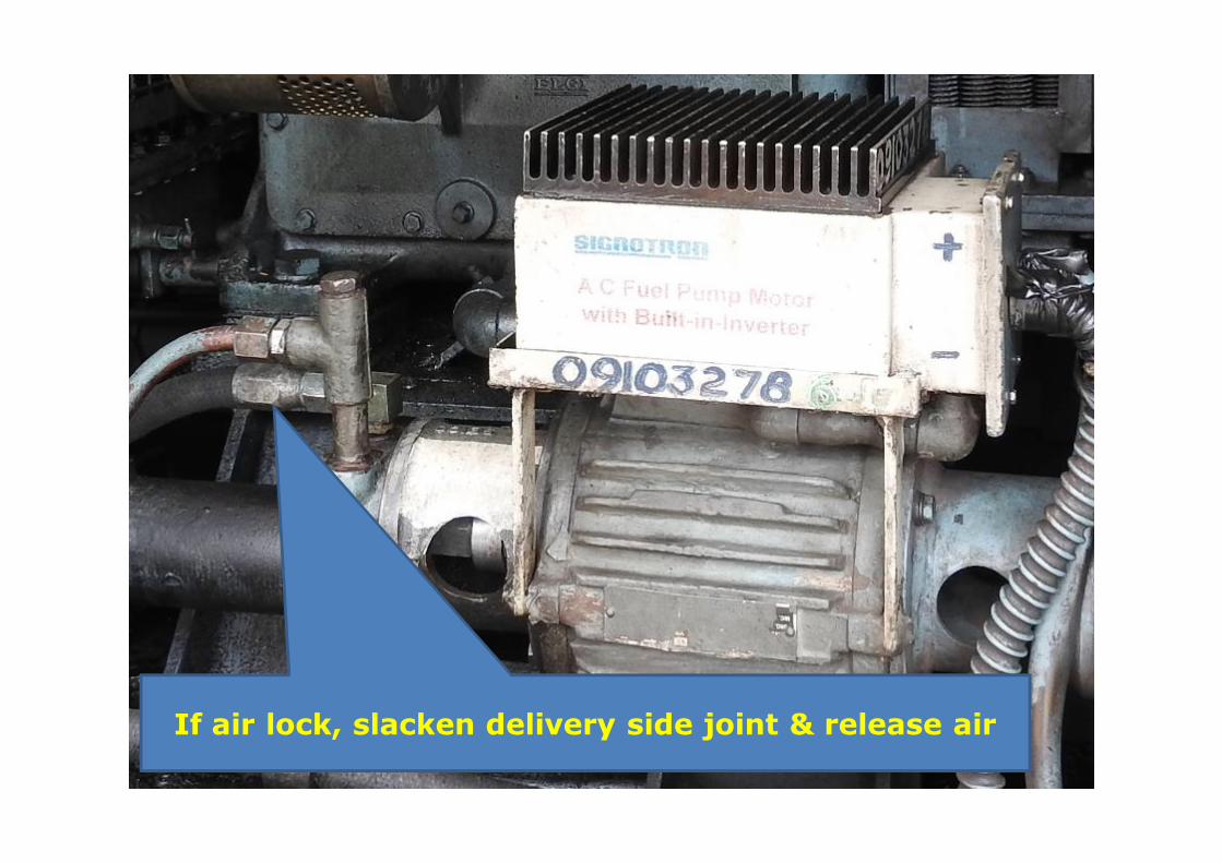
If air lock, slacken delivery side joint & release air

Fuel Relief ValveLocation Engine Free
End Right Side
Gently tap & try
Return pipe to Tank
Setting – 5.5 kg/cm2

Fuel Regulating ValveLocation Engine Free
End Left Side
Gauge / Sensor Connection
Setting – 4.4 kg/cm2

Leakage in Crossover pipeline / jointsTry to arrest leakageContact PRCLocation : Engine Power take off end both sides

If High Pressure Pipeline leaking or Unusual sound from
FIP
Lock FIP Fuel Rack
Can lock one FIP on either side

Leakage at Banjo joint or FIP damage
Can try Banjo joint Dummying

Close AESS / APU Fuel Oil pipeline COC(Connection from near Relief or Regulating Valve)
If Fuel leakage noticed after this COC / APU

AESS / APU Fuel Oil pipeline COC(Connection from near Relief or Regulating Valve)
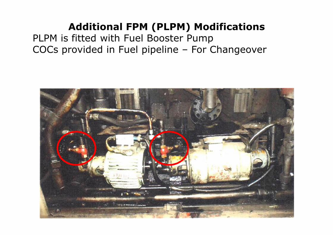
Additional FPM (PLPM) ModificationsPLPM is fitted with Fuel Booster PumpCOCs provided in Fuel pipeline – For Changeover

During FPM failure / AFPB tripping repeatedlyClose FPM COC and Open PLPM COC

• FPB to be kept always ON. • Addl. FPB to be kept ON for FPM working. • During FPM failure / Addl. FPB tripping repeatedly - Switch ON Bypass FPB

Additional Fuel Pump Breaker
Fuel Pump By Pass Breaker
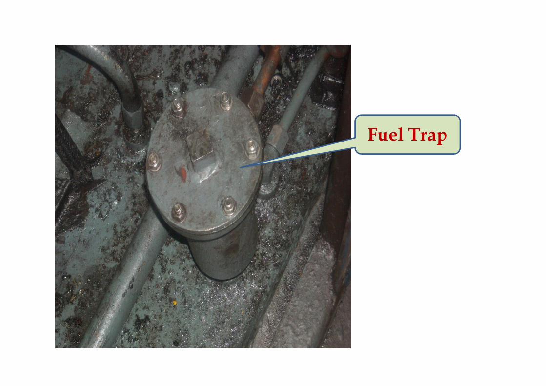
Fuel Trap

Primary Filter
Relief Valve
Secondary Filter
WDM2/WDM3A Loco Primary & Secondary Filter
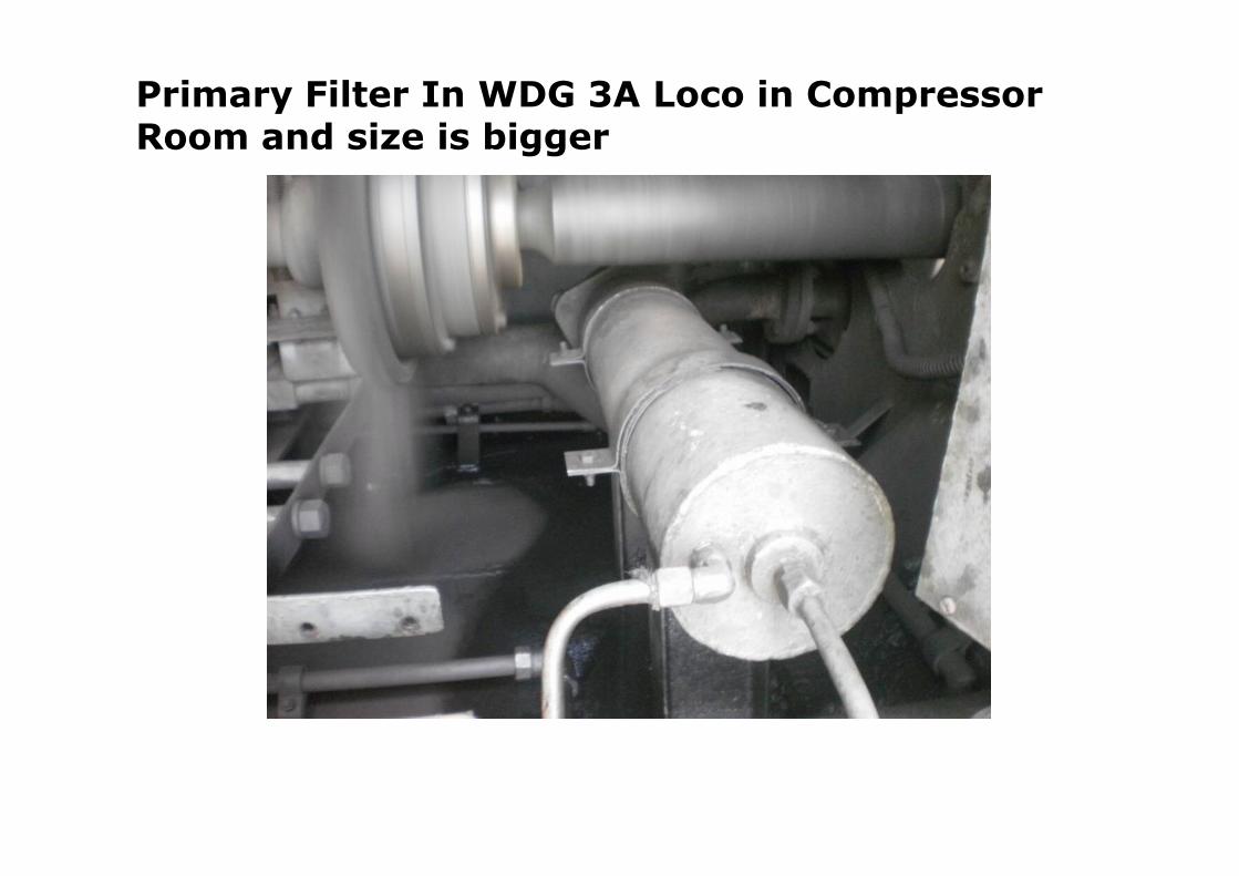
Primary Filter In WDG 3A Loco in Compressor Room and size is bigger

Primary Filter provided on right side of Engine Block in WDM3D Loco

Crossover pipe

From Left Header at Engine Free End
Regulating Valve4.4 KG/CM2
Connection To Fop Gauge In Lp’s Cab

Fuel Header
Fuel Jumper pipe / Banjo
Joint
Fuel Control Shaft

Governor Linkage connected to Fuel control
Shaft
Banjo Joint

Fuel control Shaft
Fuel Injection PumpOperated By Cam Shaft
Center cam
Fuel Rack Locking ---- Only One On
each side

Duties related to Fuelling point & others

En route examination
• Fuel balance and no leakage from tank.
• Ensure no fuel falls on engine block. Arrest leakage immediately. If not possible shutdown loco.
• For High Pressure Pipeline Leakages, FIP Locking can be done. (Only one FIP on each side).
• Glow Rod gauge leakages can be arrested by dummying it.
• Check fuel tank leakages after cattle run over / while checking under gear examination