Embed Size (px)
Citation preview

Page 1 of 14
SAE 2010-32-0020
JSAE 20109020
FUEL INJECTION for LOW EMISSION 50cc 2-STROKE
SCOOTER
P. Ravenhill, J. Allen, B. Smither, G. Farmer, Scion-Sprays Ltd, Norwich, U.K.
E.Demesse, P. Grosch, Peugeot Motorcycles, Valentigney Cedex, France.
Copyright © 2010 SAE International
ABSTRACT
The ideal attributes of light weight, low cost and high power density have made the 2-stroke engine unrivalled
in the scooter and moped market for many years.
However, the challenges of meeting new emissions regulations, especially the latest Euro III emission test cycle
have reduced the 2-stroke's dominance and it is now often considered to be too dirty and inefficient to have a
future. As a result its product placement is on the decline.
This paper introduces and discusses the latest application of a low-cost high-frequency injection system (Pulse
Count Injection [1,2]) to both the fuel flow and lubrication oil flow of a 2-stroke scooter; allowing both fluids to
be individually mapped and optimised for the complete engine operating range. This in turn enables the 2-stroke
engine to pass the latest Euro III test whilst improving the fuel economy by a considerable margin, without
changing the architecture of the engine.
Examples of the latest developments of a highly integrated engine management system, including fuel and oil
injector technology are shown.
The paper draws conclusions from the test results showing the clear benefits of electronic fuel injection both for
emissions and fuel consumption, and demonstrates that these benefits are achievable from a compact well
integrated throttle body unit suitable for the small 2-stroke engine market.
INTRODUCTION: 2-STROKE MOTOR APPLICATIONS, CONCERNS AND FUTURE
POSSIBILITIES
Although the 4-stroke engine has replaced 2-stroke engines in markets where emission legislation has been
brought in force, there are still many applications where the light weight and low cost benefits of the 2-stroke
engines are so significant as to make them irreplaceable. The lower powered, heavier and more costly 4-stroke
engine replacement would severely compromise the function and/or performance of the end product. Examples

Page 2 of 14
of these applications are the chainsaw, small outboard motor and limited capacity 'moped' or scooter, where
maximum power from a very small, lightweight and low cost engine is paramount. Examples are shown in
Figure 1.
Figure 1 Examples of applications requiring the lightweight power of a 2-stroke engine
However, even in these specialised areas there is a necessity to meet new clean emission standards and reduce
fuel consumption (CO2 emissions) in line with environmental trends. It is therefore essential that full electronic
control of the 2-stroke engine is applied in order to fully optimise the combustion and performance of these
small engines and ensure compliance with future standards. Table 1 shows the historic emissions regulation
limits for 2-stroke mopeds and the proposed new limits coming into force in 2012.
Table 1 Emission limit trend for 50cc mopeds.
Stages
Emission limits for type approval and
conformity of production for Mopeds Test cycle
CO (g/km) HC + NOx (g/km)
1999 (EURO 1) 6.0 3.0 UN-ECE Reg.47
2002 (EURO 2) 1.0 1.2 UN-ECE Reg.47
2012 (EURO 3) 1.0 1.2 UN-ECE Reg.47 Hot
and Cold Cycles
Previous work has been done showing the dramatic reduction in emissions that can be achieved with 2-stroke
engines using "Direct Injection" of the fuel into the combustion chamber [3,4,5] and this technology is often
applied to high end expensive 2-stroke engines such as high performance outboard motors and jet skis.
However, this solution while technically applicable to the smaller engines carries with it a high on-cost and
complexity which has prevented it from large scale application in the low cost markets.

Page 3 of 14
Other industrial and research work has shown that the 2-stroke engine can also be made significantly cleaner
without direct injection but rather with optimised transfer port design, stratified scavenging and accurately
controlled fuelling [6,7,8,9].
In references 6, 7, 8 & 9 the authors have presented new solutions to reducing emissions from the 2-stroke
engine but fundamental to the success of a new generation of cleaner engines is the requirement for a low cost
engine management and fuelling system. One such system is described in the next section.
LOW COST FUEL INJECTION SYSTEM
Pulse Count Injection (PCI) [1, 2] is a new and novel low cost high frequency fuel injection system designed
specifically for the small engine market (both 2 and 4 stroke engines).
Figure 2 Photo of Pulse Count Injector shown with small (Ø18mm) coin, and exploded schematic image.
The PCI technology is based around an injector that operates as a positive displacement pump, shown in Figure
2. The pumping piston in the injector can oscillate at a very wide range of frequencies, from low frequencies of
less than 1Hz to high frequencies of up to 1000Hz. Each time a piston oscillation occurs, a fixed volume of fluid
is drawn into the injector through the inlet valve and then delivered from the injector to the engine via the outlet
valve. This action is performed a controlled number of times every engine cycle with the number of pulses
injected being dependent on the engine load and speed conditions.
The PCI injector is capable of controlling the flow of a wide range of fluids, and may be used for injecting fuel
(Gasoline or Ethanol) or a pre-mixed fuel/oil solution or it may be used for metering the flow of undiluted 2-
stroke oil. For example, as shown in Figure 3, for a fuel injector in a small capacity 2-stroke engine, under no-
load conditions 1 pulse of fuel will be injected every cycle, whilst under full load at high engine speed 4 pulses
will be injected every cycle.

Page 4 of 14
Figure 3 Graphical representation of Pulse Count Injection for a 700Hz injector running on a 2-stroke engine at
10,000rpm under different load conditions.
Although the fuelling resolution shown in Figure 3 appears to be very coarse, it is in reality possible to achieve
a much finer resolution by a "pulse averaging" method as described in detail in reference 10.
In summary, the pulse averaging strategy allows fuel mapping to be calculated as a decimal number of pulses at
all conditions even though fuel can only be delivered as an integer number of pulses per engine cycle. The
software stores the decimal components of the requested pulse count until an extra full pulse is summed and
then delivers this extra pulse in the next cycle. On a typical throttlebody injected 2-stroke engine the fuel is
delivered into the crankcase and there is a reasonable fuel transport averaging from cycle to cycle, thus by using
this feature combined with the pulse averaging strategy a fine fuelling resolution can be achieved. The results
of pulse averaging at an idling condition of 1500rpm are shown graphically in Figure 4. In this test each point is
a stable engine operating condition held for approximately 30secs, the emissions are measured engine-out
emissions with the secondary air injection closed off. The emissions were measured using a Horiba Mexa-
554GE analyser. The CO results are the direct measurement whilst the total hydrocarbons (THC) are calculated
from a n-hexane measurement using an infrared sensor with a fixed conversion factor. The lambda
measurement is a calculated value based on engine-out emissions and calculations derived in reference 11. The
graph shows that fuelling refinement is achievable to two decimal places of pulse averaging with the engine and
engine-out emissions responding stably and linearly to the fine changes in pulse count.
0° 360°
2-stroke engine cycle at 10,000rpm = 6ms
1.4ms = 700Hz = Injector operating frequency
No Load
½ Load
Full Load
1 Pulse = Fixed Volume of fuel
(1.4µLtrs)

Page 5 of 14
Engine-out Emissions with Pulse Count Averaging at Idle
0
0.5
1
1.5
2
2.5
3
3.5
0.8 0.85 0.9 0.95 1 1.05 1.1 1.15 1.2 1.25 1.3
Average Pulse Count per Cycle
CO
%(v
ol)
, L
am
bd
a
6
6.5
7
7.5
8
8.5
9
9.5
10
10.5
11
TH
C %
(vo
l)
CO% at 1500rpm
lambda at 1500rpm
THC% at 1500rpm
Figure 4 Engine-out emissions at a 1500rpm idle condition across a range of air-fuel ratios using Pulse Count
Averaging fuelling strategy.
The injector geometry specifications are optimised to achieve the required fuel delivery for each specific
application based on maximum fuel flow at high load and speed and minimum fuel flow at idle with sufficient
air-fuel ratio resolution with pulse averaging. By controlling the fuel flow and injecting fuel in this unique high
frequency manner, the whole fuel handling system can be consolidated and miniaturised. The injector shown in
Figure 2 performs all the functions of the conventional fuel pump, pressure regulator, and injector metering
device.
The electrical power consumption for the injector (no additional pump required) at full load condition is less
than 6Watts. And under idle conditions, when only one pulse per cycle is being used at 1500rpm the power
consumption is only 0.3Watts. The ECU itself consumes approximately 0.6W.
The PCI system used as a fuel injector does not require a pressurising pump and as a result does not need high
pressure fuel pipes. To be fully functional the injector only needs a reservoir of fuel around it, and on
applications where there is a head of fuel due to the positioning of the tank (e.g. on a motorcycle - see Figure 5)
only a simple supply pipe and vent pipe arrangement is necessary. If the fuel tank is below the injector, an
additional low cost crankcase driven diaphragm type fuel pump is required.
Page 6 of 14
Figure 5 Comparison of fuel components between PWM and PCI systems.
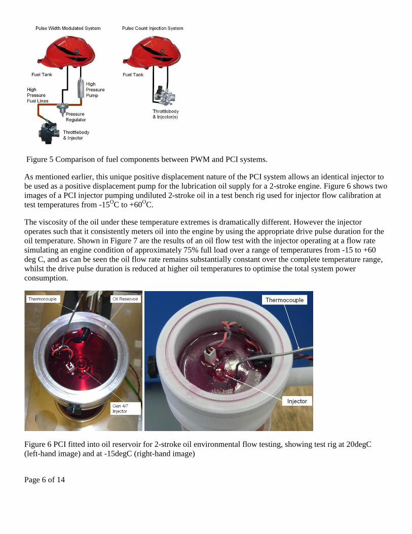
As mentioned earlier, this unique positive displacement nature of the PCI system allows an identical injector to
be used as a positive displacement pump for the lubrication oil supply for a 2-stroke engine. Figure 6 shows two
images of a PCI injector pumping undiluted 2-stroke oil in a test bench rig used for injector flow calibration at
test temperatures from -15OC to +60
OC.
The viscosity of the oil under these temperature extremes is dramatically different. However the injector
operates such that it consistently meters oil into the engine by using the appropriate drive pulse duration for the
oil temperature. Shown in Figure 7 are the results of an oil flow test with the injector operating at a flow rate
simulating an engine condition of approximately 75% full load over a range of temperatures from -15 to +60
deg C, and as can be seen the oil flow rate remains substantially constant over the complete temperature range,
whilst the drive pulse duration is reduced at higher oil temperatures to optimise the total system power
consumption.
Figure 6 PCI fitted into oil reservoir for 2-stroke oil environmental flow testing, showing test rig at 20degC
(left-hand image) and at -15degC (right-hand image)

Page 7 of 14
Oil Injector Flow v's Oil Temp
0
10
20
30
40
50
60
70
80
90
100
-15 -10 -5 0 5 10 15 20 25 30 35 40 45 50 55 60
Oil Temperature Deg C
Oil F
low
cc
/hr
& P
uls
e D
ura
tio
n m
s
Injector Drive Pulse Duration ms
Oil Flow cc/hr
Figure 7 Oil flow rates (cc/hr) with oil temperatures from -15 to +60 Deg C.
Used in this manner the PCI injector can deliver a calibrated and specific amount of oil to the engine depending
on engine speed, load and temperature. This precise control of the oil flow throughout the engine operating
range allows complete optimisation of oil flow under all operating conditions and can visually eliminate blue oil
smoke traditionally associated with low cost 2-stroke engines by moving beyond the limitations of a fixed
oil/fuel ratio.
The addition of the oil control and delivery system may be executed in 2 different methods; either a separate oil
system can be fitted to the 2-stroke engine (as often seen on more expensive applications - e.g. jet-ski, Direct
Injection engines) with the oil being delivered directly to several engine components requiring lubrication. Or
the alternative is to deliver the precisely metered oil quantity into the fuel stream just prior to its introduction
into the crankcase. This latter approach is the preferred low cost solution as the oil injector and fuel injector can
then be housed together in a single throttle-body assembly along with the ECU and sensors thus minimising
overall cost.
By using such a highly integrated system, much of the cost of a conventional fuel injection system is either
reduced or removed. The reduced parts count allows connection simplification and direct mounting of the ECU
on to the throttle body.
Figure 8 shows a schematic drawing and the hardware of a fully integrated throttle-body unit which contains all
the aforementioned items, Figure 9 shows the actual integrated system fitted to a scooter.

Page 8 of 14
Figure 8 Schematic and hardware image of integrated 2-Stroke throttlebody with separate fuel and oil metering
injectors
Figure 9 Installed prototype hardware on 50cc scooter
APPLICATION TO A 50cc 2-STROKE MOTORCYCLE ENGINE
Following on from the prototype work, discussed in the previous section, a full production program is now
underway to apply the PCI technology to a 50cc 2-stroke scooter using the unique properties of the injector to
enable a highly integrated compact throttle body unit.
The production system contains: 2 PCI injectors (1 for fuel and 1 for oil), a fully programmable ECU PCB with
on board sensors and electronic throttle control motor, all in one fully integrated module.

Page 9 of 14
The production system can be seen as a schematic in Figure 10 and as a fitted unit in Figure 11 applied to the
50cc engine, with covers removed. Figure 12 shows the 50cc scooter undergoing calibration and emission work
on a chassis dynamometer.
Figure 10 Schematic of the production intent throttle body with fuel and oil injection system for a 50cc scooter.
Figure 11 Photo of installed Fuel Injection system on 50cc scooter with covers removed.

Page 10 of 14
Figure 12 Photo of 50cc scooter mounted on emission test facility.
The control processor for this application is based on the 32-bit Arm-7 microprocessor chip using MISRA-C
compliant in-house software with K-Line diagnostics functionality.
The interface software, which is also in-house developed, gives a MS Windows compatible system with very
intuitive and easy to use calibration functionality, shown in Figure 13.
Figure 13 Windows compatible interface of the calibration software
The scooter is equipped with a two-way catalyst and passive secondary air injection system. The software is
configured to give rapid catalyst warm up and optimum emission conversion during normal engine operation
resulting in minimum emission output.
Scooters sold in the 50cc market segment in Europe and else where are speed restricted generally speaking for
under-17 year olds riders and de-restricted for over 17 year olds, however the legal speed definitions often vary
from country to country. To achieve the different speed restrictions the speed was generally governed by
altering the CVT ratio and de-tuning the exhaust system, or it is sometimes achieved by altering the spark
advance (making the engine run very retarded in some cases), these running conditions all have a serious

Page 11 of 14
negative effect on fuel consumption. In contrast the production PCI system is equipped with an electric throttle
control system (drive-by-wire) and this combined with a vehicle speed sensor allows the regulatory speed limit
to be met whilst maintaining maximum engine efficiency.
Three calibration tables are shown in Figure 14 which are, from the top, the basic fuel map, an oil flow map and
the ignition advance table for the engine. Each one of these functions can be calibrated separately for different
engine load and speed conditions. There are also specific functions for other engine conditions such as: hot-
start, cold-start, transient acceleration and engine over-speed protection.
Figure 14 Base calibration maps for: top) fuel requirement, middle) oil flow, bottom) ignition advance.
As can be seen in the oil map shown in Figure 14, the oil flow volume can be reduced down to a minimum
(even zero as shown) at low engine speed and load conditions. This ability to optimise the oil flow has virtually
eliminated the visual blue smoke still so typical of many 2-strokes engines. Apart from the direct replacement of
the carburettor with the new PCI EFI system, the only other modification to the engine has been the addition of
an engine temperature sensor. Back-to-back steady state comparisons with the standard carburetted scooter
shown in Figures 15a, 15b, and 15c, clearly demonstrate the ability to easily vary the fuelling setting between a
richer or weaker mixture and demonstrate emission reductions of up to 68% reduction in HC and over 80%
reduction in CO, against a small increase in NOx.

Page 12 of 14
Figure 15 Steady state emission comparison of carburetted engine with PCI EFI system operating at a lean and
rich condition, a) Idle, b) 20% throttle, c) 45% throttle.
Early emission tests of the 50cc engine with the PCI EFI system using the ECE47 Euro 3 emission cycle, shown
in Figure 16, have demonstrated a pass at Euro 3 limits. The ECE47 Euro 3 legislation, shown in Table 1 and
figure 16, has not actually been finalised yet however the weighting between the Hot and Cold phases in this
instance has been based on the mileage covered in each of the phases which on the ECE47 is almost 1:1.
As can be seen from the emission results in Table 2, there is a significant reduction in all measured emissions
compared with the carburettor equipped engine which not only results in a Euro III pass but also achieves a
16% reduction in fuel consumption. Further calibration work is now underway to achieve further reductions in
emissions and driveability refinements.

Page 13 of 14
Figure 16 ECE47 Euro 3 drive cycle for 50cc mopeds, the 4 hills drive cycle is repeated 2 times for each
emission test, once as "cold" and once as "hot"
Table 2 Initial Euro 3 emission results from early prototype fuel injection system compared to carburettor
equipped engine.
CO
g/km
CO2
g/km
HC
g/km
NOX
g/km
HC + NOX
g/km
Consumption
l/100km
ECE47-Euro 3 Limits 1.000 1.200
Carburettor Test results 1.666 64.377 2.665 0.090 2.754 3.290
PCI EFI Test results 0.956 57.971 1.057 0.051 1.108 2.749
SUMMARY/CONCLUSIONS
Two-Stroke engines still offer a unique low-cost and lightweight solution for specific applications, which can
not easily be replaced with 4-stroke engines.
Two-Stroke engines can be improved to significantly reduce emission output. This can be achieved by either
expensive Direct Injection fuel systems or with low-pressure low-cost crankcase fuel injection systems.
Pulse Count Injection (PCI) technology can be applied to both fuel injection and lubrication oil metering on a
two-Stroke engine.
With the PCI oil and fuel injector being identical, a very compact well integrated electronic engine control
system has been manufactured that allows direct replacement of a standard carburettor on a two-stroke engine
requiring only minimal changes to the base engine.
Euro 3 emission targets have been achieved on a 50cc two-stroke scooter with no changes to the base engine
combustion system.
By controlling the oil injection a smokeless operation can be safely achieved with no damage to the engine
occuring.

Page 14 of 14
Over 16% reduction in fuel consumption has been achieved with PCI EFI compared to the carburettor equipped
engine.
Further development work on the engine combustion system and transfer port design can still be done which are
likely to further improve emissions performance and allow future emissions targets to be met.
REFERENCES
1. J.Allen, P.Ravenhill, Flow and Spray Characteristics of a High Frequency Low Cost Fuel Injection System
for Small Engines., ICLASS-2006, Kyoto, Japan. Paper no. ICLASS06-243
2. P. Ravenhill, T. Drake, R.Hoolahan, B.Smither, I.McFarlane, J. Allen, G.Farmer, Low Cost Electronic Fuel
Injection for Motorcycles and Utility Engines. SETC 2009, Penang, Malaysia; paper no. 2009-32-0149 /
20097149
3. R.Houston, M.Archer, M.Moore, R.Newman, Development of a Durable Emission Control System for an
Automotive Two-Stroke Engine. SAE Paper no. 960361
4. P.Duret, J.Moreau, Reduction of Pollutant Emissions of the IAPAC Two-Stroke Engine with Compressed
Air Assisted Fuel Injection", SAE Paper No. 900801, 1990.
5. G.Blair, R.Kee, C.Carson, R.Douglas, The Reduction of Fuel Consumption by Direct Air-Assisted Fuel
Injection into a Two-Stroke Engine. 4th Graz Two-Wheeler Symposium, April 1991.
6. F.Winkler, Low presssure fuel injection strategies for low emission two stroke scooter engines. Graz
University of technology, 2-Stroke Symposium, Monza, 2009.
7. G.Cunningham, R.Kee, R.Kenny, W.Skelton, Development of a Stratified Scavengine System for Small
Capacity Two-Stroke Engines, 1999 SETC. SAE Paper 1999-01-3270 / 9938025.
8. Stihl advanced 2-stroke engine with Stratified Scavenging
http://www.stihl.com/isapi/default.asp?contenturl=/knowhow/producttechnics/stihlengines/2_stroke/default.
htm
9. M. Gaxnthner, M. Mugele, J. Tribulowski, U. Spicher, H. Rosskamp, Numerical analysis of an air-head
stratified scavenging concept for emission reduction of a two-stroke engine, SAE Paper 2001-24-0051
10. J.Allen, T.Drake, Experimental Results of New Fuelling Strategies for High Frequency Low Cost Injection
Systems for Small Engines, SETC 2007, Paper no. 20076551 / 2007-32-0051
11. R.Douglas, AFR and Emissions Calculations for Two-Stroke Cycle Engines, SAE Paper no. 901599