Embed Size (px)
Citation preview

0 9/12/2009 SM GN GN
Rev. Date Prepared by Checked by Approved by
MATRIX SOLUTIONS302, VITC MODEL EXPORT PARK488, 14TH CROSS, 4TH PHASEPEENYA INDUSTRIAL AREABANGALORE - 560 058INDIAPH: 080 2836 7680
Chhoti Nehar,MalakpurPIONEER INDUSTRIES LIMITED
DOC. NO : 4 - 2676 - MECH - 005
TECHNICAL SPECIFICATION FOR FUEL HANDLING SYSTEM
Punjab, INDIAPathankot – 145 025.

PIONEER INDUSTRIES LTD., PATHANKOT, PUNJAB. 3 MW CAPTIVE POWER PLANT
TECHNICAL SPECIFICATION FOR FUEL HANDLING SYSTEM.
MATRIX SOLUTIONS BANGALORE. Page : 1
CONTENTS
1. Introduction
2. System Description
3. Codes and Standards
4. Design Criteria
5. Scope of Work
6. Scope of Service
7. Exclusions
8. Terminal Points
9. Noise Level
10. Painting
11. System Performance & Availability
12. List of Vendors
DATA SHEET Data Sheet 01 Belt Conveyor
Data Sheet 02 Belt Weighers
Data Sheet 03 Metal Detector
Data Sheet 04 Overband Magnetic Separator
Data Sheet 05 A.C. Motor
Data Sheet 06 Local Pushbutton Station
Data Sheet 07 Motor Control Center
Data Sheet 08 Cables
Data Sheet 09 Belt Vulcaniser
Data Sheet 10 Ground hopper
Data Sheet 11 Vibratory feeder
Data Sheet 12 Screen
Data Sheet 13 Crusher
PIONEER INDUSTRIES LTD., PATHANKOT, PUNJAB. 3 MW CAPTIVE POWER PLANT
TECHNICAL SPECIFICATION FOR FUEL HANDLING SYSTEM.
MATRIX SOLUTIONS BANGALORE. Page : 2
SCHEDULES Schedule 01 Price Schedule
Schedule 02 Technical Deviations
Schedule 03 Commercial Deviations
Schedule 04 Weights & Dimensions
Schedule 05 Special Tools & Tackles for Maintenance
Schedule 06 Recommended Operational Spares
Schedule 07 Schedule of Design, Engineering, Manufacturing,
Shipment, Erection & Commissioning
Schedule 08 Schedule of Drawings & Documents
Schedule 09 Guarantee
DRAWINGS 01. Scheme for Fuel Handling System (3-2676-100-006). 02. Layout of Fuel Handling System (1-2676-100-009). 03. Power house layout (1-2676-100-004).(for showing the location of MCC & control panels)

PIONEER INDUSTRIES LTD. PATHANKOT, PUNJAB. 3 MW CAPTIVE POWER PLANT
TECHNICAL SPECIFICATION FOR FUEL HANDLING SYSTEM.
------------------------------------------------------------------------------------------------------------------------------------- MATRIX SOLUTIONS BANGALORE. Page: 3
1.0 Introduction The 3 MW Captive Power Plant by Pioneer Industries Ltd. at Pathankot, Punjab. has one number 25 TPH AFBC boiler generating steam at 67 kg/cm2 (g) 490 ± 5 °C. The boiler is designed for firing 100% Rice husk or 100% Coal. The Boiler is also designed for capable of firing different combination of Coal and Bio-mass fuels like Rice husk and wood chip. This specification covers the design, engineering, manufacturing, inspection, and delivery at site, erection, testing, commissioning and handing over of the fuel handling system. The scope of work and services shall include all necessary work and supply of equipment and material whether mentioned in these specifications or not, but are necessary for the satisfactory, reliable safe operation and maintenance of the system and required for achieving guaranteed performance of the system. 2.0 System Description (Ref: Scheme for Fuel Handling system Drg. No: 3-2676-100-006) 2.1 Coal handling system The conveying system from ground hopper upto the coal bunker shall be designed to handle coal. The size of the ROM coal is –200mm with about 20% less than 6mm. The coal handling plant shall be designed to operate for a period of 16 hours per day only. The coal conveyors shall be designed to achieve a throughput of 8 tph. The ROM coal is received at site from the trucks and is unloaded at the coal yard (By Purchaser). Using front end loaders, the coal is reclaimed from the stock pile and dumped on to 1 nos. of ground hoppers arranged over the belt conveyor BC1 along the length of the stock pile. The ground hopper capacity shall be minimum 5 tons. The centre line of the bottom opening of the hopper shall be just above the BC1 conveyor and the discharge through the opening shall commensurate with the conveyor capacity. The ground hopper shall be provided with a rod type isolation gate and vibratory feeder. Coal from the fixed ground hoppers is discharged onto a belt conveyor BC1 which feeds the coal to the crusher/screen. One metal detector and one over band magnetic separator are provided on conveyor BC1 to remove iron materials from the coal. The crusher house houses 1x100% crusher, gate before screen and 1x100%screen. The crusher shall be designed to reduce the size of the coal from –200mm to –25mm. The efficiency of the crushers shall be minimum 80% even during the monsoon period. The coal of size < 6 mm is transferred directly through the screen on to coal conveyor BC2. The larger size coal is screened and fed back to the crusher and the same shall be conveyed from BC2 to covered shed The conveyor BC3 transfers the crushed coal to a divert chute from ground hopper and from divert chute to coal bunker as shown in the schematic diagram. 2.2 Bio-mass fuel handling system : The biomass is loaded to ground hopper through front end loaders as shown in the fuel handling scheme drawing and the system shall be designed to achieve a throughput of 8 TPH designed to operate continuously. The wood chip size is less than 10-12 mm

PIONEER INDUSTRIES LTD. PATHANKOT, PUNJAB. 3 MW CAPTIVE POWER PLANT
TECHNICAL SPECIFICATION FOR FUEL HANDLING SYSTEM.
------------------------------------------------------------------------------------------------------------------------------------- MATRIX SOLUTIONS BANGALORE. Page: 4
3.0 Codes and Standards: The design and manufacturing of the conveyors and accessories shall comply with the requirements of applicable Indian standards such as the following and those standards specified therein, in so far as they apply. a. IS 800 : Code of practice for Construction in steel b. IS 875 : Code of practice for design loads for buildings/structures. c. IS 1893 : Criteria for earthquake resistance design of structures. d. IS 11592 : Code of practice for selection and design of belt conveyors e. IS 8531 : Pulleys for belt conveyors f. IS 8598 : Idlers and idler sets for Belt conveyors g. IS 14386 : Belt conveyors – Traveling trippers h. IS 1891 : Conveyor belting i. IS 9295 : Steel tubes for idlers for belt conveyors j. IS 4776 : Toughed belt conveyors – Surface installation k. IS 806 : Code of practice of steam tubes in general engineering l. BS 4592 : Industrial type metal floors, walkways and stair m. BS 5395 : Stairs, ladders and walkways. n. IS 8130 : Conductors for insulated electrical cables and flexible chords o. IS 3975 : Mild steel wires, strips and tapes for armoring of cables p. IS 2633 : Methods of testing weight, thickness and uniformity of coating on hot
dipped galvanized articles q. IEC 540 & 540A: Test methods for insulation and sheaths of electric cables and chords. 4.0 Design Criteria The Bidder shall study the specification and satisfy himself thoroughly regarding the workability and suitability of the equipment and system supplied by him to satisfy this specification. He shall take full responsibility for the guaranteed and satisfactory performance of the system. All the working parts shall be designed and so arranged for convenience of operation, maintenance, inspection, lubrication and ease of replacement with minimum downtime. All like parts on equipment furnished or on duplicate equipment are to be inter-changeable. Efforts should be made to minimize the variety of respective items like belts, slats, Chain links, Sprockets, idlers, bearings etc.,
PIONEER INDUSTRIES LTD. PATHANKOT, PUNJAB. 3 MW CAPTIVE POWER PLANT
TECHNICAL SPECIFICATION FOR FUEL HANDLING SYSTEM.
------------------------------------------------------------------------------------------------------------------------------------- MATRIX SOLUTIONS BANGALORE. Page: 5
to maximize inter-changeability. Spillage of fuel from conveyors have to be prevented through proper design of handling system. Suitable modifications will have to be carried out if spillage is not prevented without any additional cost. All equipment shall be complete with adequate safety devices wherever a potential hazard to personnel exists and with provisions for safe access to personnel to and around equipment for operation and maintenance functions. These items will include not only those usually furnished with elements of machinery but also the additional covers, guards, handrails etc., which are necessary for safe operation. The Bidder shall carryout tests on raw materials, where necessary for arriving at proper design parameters of equipment to be supplied. 4.1 Site Data: PURCHASER : M/s.Pioneer Industries Ltd. Project Title : 3 MW Captive Power Plant. Location : Pathankot, Punjab, India. Data for Seismic Design : As per IS: 1893 Soil bearing capacity At 2.0 m depth : 20.0 T/M2
At 3.0 m depth : 25.2 T/M2
5.0 Scope of Work: The scope of work and services shall include all necessary design work, detailed engineering, supply of documents and drawings, supply of conveying equipments, all structural support, Junction towers, walkways, platforms, electrical drives, gear boxes, control panel, (control desk with mimic and annunciator panel), design and supply of MCC, power cables, control cables, instrumentation cables, cable trays etc., testing at manufacturers work, packing, forwarding, unloading at site, handling, storing, leading the materials to the work spot, erection, testing, commissioning, trial run, reliability running, performance testing and handing over the complete system after successful full load trials. The length and elevations indicated in the drawing are indicative. Bidder shall furnish the exact length of the conveyors based on his design. The scope of work and any other services, not specifically mentioned above but are necessary to complete the system in all respects regardless of any omission in this specification or drawings shall deemed to have been included in the supplier’s scope. All materials supplied under this contract shall be new and unused. 5.1 Scope of supply: 5.1.1 Mechanical 5.1.1.1 Belt conveyors BC-1, BC-2 and BC-3 with drives and technological structures for fuel
handling consisting of the following main components given below:
PIONEER INDUSTRIES LTD. PATHANKOT, PUNJAB. 3 MW CAPTIVE POWER PLANT
TECHNICAL SPECIFICATION FOR FUEL HANDLING SYSTEM.
------------------------------------------------------------------------------------------------------------------------------------- MATRIX SOLUTIONS BANGALORE. Page: 6
a) Belting b) Pulleys c) Idlers (carrying idlers, return idlers and impact idlers) d) Drive motor e) Gear box f) Couplings g) Bearings h) Drive frame i) Hold back j) Take up k) Internal and external scrappers l) Deck plate m) Skirt board n) Transfer chutes o) Junction towers, roof side covers, ladders etc. p) Metal detector and over band magnetic separators for Coal conveyor. q) Stringer and short support columns r) Head frame, tail frames and frames for the pulleys and take up s) 1 no. Rack and pinion gates for the ground hoppers. t) 1 no of vibratory screen at the outlet of the ground hoppers.
5.1.1.2 Crusher House with shed with 1 No. crusher, screens and gates. (BIDDER to clearly
specify load details, space requirement, foundation plan and any other load to be considered for the purchaser to design the foundation. The overall dimensions of the crusher house with General Arrangement Drawing shall be submitted along with the offer.
5.1.1.3 One number belt weigh scale for BC3 conveyor. 5.1.1.4 One number of fixed ground hoppers in the coal yard with grizzley Ground hoppers for
coal shall have internal linears of 12 mm thick, Material SAILMA/TISCROL/UHMW. 5.1.1.5 One number Grissley hopper for Bio-mass fuel with rod gate arrangement 5.1.1.6 Gantries, walkways, galleries and ladders for all conveyors wherever required for
observation and maintenance for conveyor. Walkway shall be provided on one side for conveyors. The conveyor galleries / walkways will not be covered. Only the conveyor will be covered with hood made of M.S sheet.
5.1.1.7 Supporting structures (For the shuttle conveyor, the primary structure available from the
boiler can be used; Bidder to consider all secondary members for supporting) 5.1.1.8 Anchor bolts and double nuts for all supports and encasing for conveyor structures with
concrete that are located above ground in the fuel storage yard. 5.1.1.9 Sealing arrangement for the coal bunker 5.1.1.10 Grouting and grouting materials with templates 5.1.1.11 Two coats of red oxide primer and two coats of synthetic enamel finish paint (Colour –
grey)
PIONEER INDUSTRIES LTD. PATHANKOT, PUNJAB. 3 MW CAPTIVE POWER PLANT
TECHNICAL SPECIFICATION FOR FUEL HANDLING SYSTEM.
------------------------------------------------------------------------------------------------------------------------------------- MATRIX SOLUTIONS BANGALORE. Page: 7
5.1.1.12 Special tools and tackles. 5.1.1.13 Commissioning spares 5.1.1.14 2 years operational spares list with price offer. 5.1.1.15 Necessary drawings and documents for the regular operation and maintenance of the
complete plant. Catalogues of any bought out items like Crushers, Gearboxes, couplings, drive motors etc., are to be compiled neatly and the model/type of the equipment supplied shall be clearly marked in these documents.
5.1.1.16 Dust extraction system to be considered for Crusher House, Transfer towers and in the
bunker house including electrical and instruments. 5.1.1.17 Belt vulcanizing kit. 5.1.2 Electrical 5.1.2.1 Design and supply of MCC for fuel handling, crushers, shredders/cutters, conveyor
motors, etc. These MCC panels will be located in the Power house building (0 mtr level). 5.1.2.2 Supply of power and control cables with cable trays. 5.1.2.3 Control desk, Mimic and Annunciator Panel. The control desk shall consist of a mimic
panel with push buttons for operation of conveyors, ammeters with selector switches like auto / manual and local / remote etc. for all the drives.
5.1.2.4 All electrical drives required for effective functioning of the system 5.1.2.5 Push button stations for local operation of 1 no. for each all conveyors, dust extraction
system etc., 5.1.2.6 Junction boxes and other erection hardwares 1 lot 5.1.2.7 Safety switches (pull cord switch, belt sway switches Zero speed switches as part of hard
wired /Control System) 1 lot 5.1.2.8 Limit switches for gates before the screens as required 5.1.2.9 Lighting system for the total fuel handling inclusive of crusher house, conveyors etc.,
along with necessary distribution boards, cables and light fixtures 1 lot 5.1.2.10 Instrument Cables. 5.1.2.11 Earthing materials for all equipment covered under this scope upto the main earth mat. 5.1.2.12 Lightning protection materials 5.1.2.13 Cable Trays, junction boxes and other erection hardware. 5.1.2.14 Any other items which is not specifically included but are necessary for the normal
operation/safe operation of the system.
PIONEER INDUSTRIES LTD. PATHANKOT, PUNJAB. 3 MW CAPTIVE POWER PLANT
TECHNICAL SPECIFICATION FOR FUEL HANDLING SYSTEM.
------------------------------------------------------------------------------------------------------------------------------------- MATRIX SOLUTIONS BANGALORE. Page: 8
5.2 Scope of Services 5.2.1 Final grouting of all structures and equipments. 5.2.2 Necessary clearances and approvals required from the Electrical Inspectorate of State
Government. 5.2.3 Erection of MCC, Control Desk, motors, LCS, power cables and control cables including
cable trays. 5.2.4 Erection of safety switches of the conveyor. 5.2.5 Earthing connection. 5.2.6 Inspection and Testing 5.2.7 Trial run and pre-commissioning test 5.2.8 Performance guarantee trials 5.2.9 Any other services which are not specifically mentioned but are essential for the system
completion shall be included in the scope of services. 5.3 Work by Others:
a. Owner shall supply, lay and terminate power cable from PCC to Bidder’s MCC. b. Service water for spray will be provided by the Purchaser at one point near the Boiler.
5.4 Detailed Technical Specification: 5.4.1 Belt Conveyors: 5.4.1.1 All belt conveyors shall be designed, manufactured and supplied in accordance with the
code IS 11592. 5.4.1.2 The maximum inclination of conveyor belt shall be restricted to 16 Deg. and the
maximum declination shall not exceed 12 degrees. Inclination of conveyor on the loading zone shall be restricted to a maximum of 6 degree to horizontal unless agreed otherwise.
5.4.1.3 The linear speed of belt conveyors shall not exceed 1m/min. 5.4.1.4 Adequate number of locating pins and match marking shall be provided for easy
assembly and dismantling.
PIONEER INDUSTRIES LTD. PATHANKOT, PUNJAB. 3 MW CAPTIVE POWER PLANT
TECHNICAL SPECIFICATION FOR FUEL HANDLING SYSTEM.
------------------------------------------------------------------------------------------------------------------------------------- MATRIX SOLUTIONS BANGALORE. Page: 9
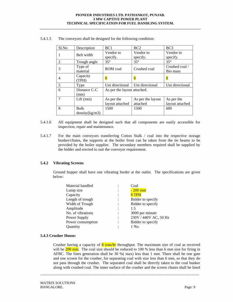
5.4.1.5 The conveyors shall be designed for the following condition:
Sl.No Description BC1 BC2 BC3
1 Belt width Vendor to specify.
Vendor to specify.
Vendor to specify.
2 Trough angle 35° 35° 35°
3 Type of material ROM coal Crushed coal Crushed coal /
Bio mass
4 Capacity (TPH) 8 8 8
5 Type Uni directional Uni directional Uni directional 6 Distance C-C
(mts) As per the layout attached.
7 Lift (mts) As per the layout attached
As per the layout attached
As per the layout attached
8 Bulk density(kg/m3)
1500 1500 600
5.4.1.6 All equipment shall be designed such that all components are easily accessible for
inspection, repair and maintenance. 5.4.1.7 For the main conveyors transferring Cotton Stalk / coal into the respective storage
bunker/chutes, the supports at the boiler front can be taken from the tie beams to be provided by the boiler supplier. The secondary members required shall be supplied by the bidder and erected to suit the conveyor requirement.
5.4.2 Vibrating Screens
Ground hopper shall have one vibrating feeder at the outlet. The specifications are given below:
Material handled : Coal Lump size : - 200 mm Capacity : 8 TPH Length of trough : Bidder to specify Width of Trough : Bidder to specify Amplitude : 1.5 No. of vibrations : 3000 per minute Power Supply : 230V / 440V AC, 50 Hz Power consumption : Bidder to specify Quantity : 1 No.
5.4.3 Crusher House:
Crusher having a capacity of 8 tons/hr throughput. The maximum size of coal as received will be 200 mm. The coal size should be reduced to 100 % less than 6 mm size for firing in AFBC. The fines generation shall be 30 %( max) less than 1 mm. There shall be one gate and one screen for the crusher, for separating coal with size less than 6 mm, so that they do not pass through the crusher. The separated coal shall be directly taken to the coal bunker along with crushed coal. The inner surface of the crusher and the screen chutes shall be lined
PIONEER INDUSTRIES LTD. PATHANKOT, PUNJAB. 3 MW CAPTIVE POWER PLANT
TECHNICAL SPECIFICATION FOR FUEL HANDLING SYSTEM.
------------------------------------------------------------------------------------------------------------------------------------- MATRIX SOLUTIONS BANGALORE. Page: 10
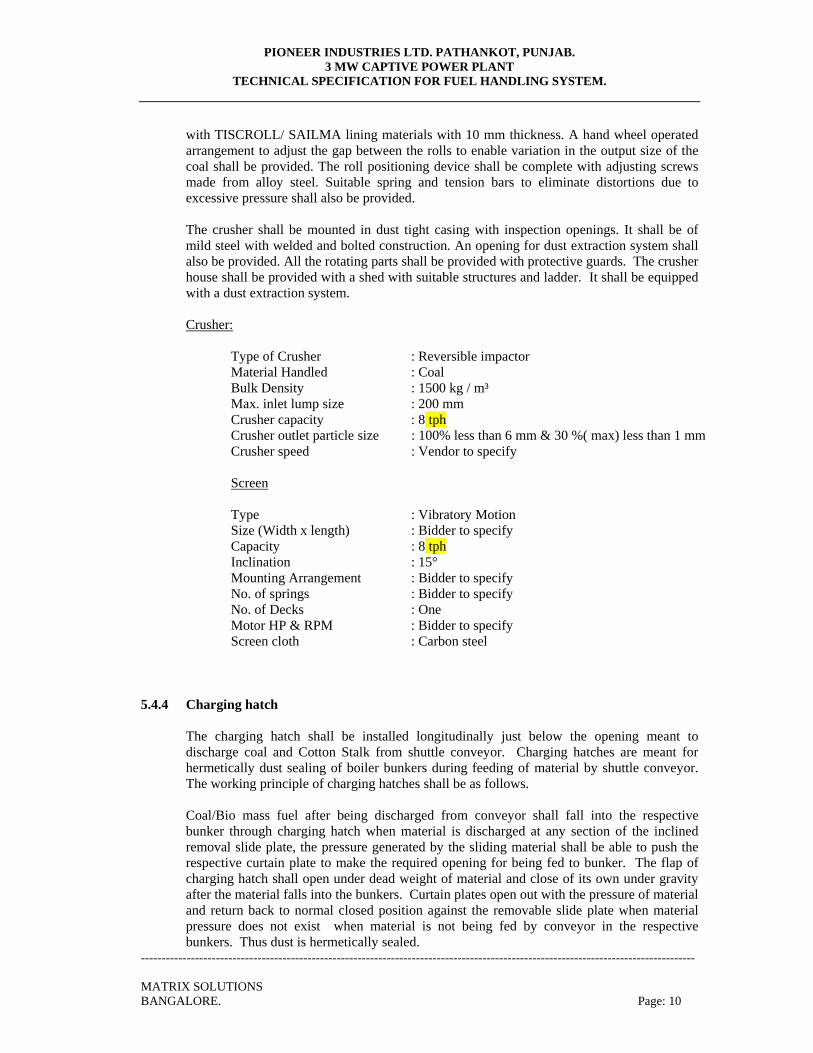
with TISCROLL/ SAILMA lining materials with 10 mm thickness. A hand wheel operated arrangement to adjust the gap between the rolls to enable variation in the output size of the coal shall be provided. The roll positioning device shall be complete with adjusting screws made from alloy steel. Suitable spring and tension bars to eliminate distortions due to excessive pressure shall also be provided. The crusher shall be mounted in dust tight casing with inspection openings. It shall be of mild steel with welded and bolted construction. An opening for dust extraction system shall also be provided. All the rotating parts shall be provided with protective guards. The crusher house shall be provided with a shed with suitable structures and ladder. It shall be equipped with a dust extraction system.
Crusher:
Type of Crusher : Reversible impactor Material Handled : Coal Bulk Density : 1500 kg / m³ Max. inlet lump size : 200 mm Crusher capacity : 8 tph Crusher outlet particle size : 100% less than 6 mm & 30 %( max) less than 1 mm Crusher speed : Vendor to specify
Screen Type : Vibratory Motion Size (Width x length) : Bidder to specify Capacity : 8 tph Inclination : 15° Mounting Arrangement : Bidder to specify No. of springs : Bidder to specify No. of Decks : One Motor HP & RPM : Bidder to specify Screen cloth : Carbon steel
5.4.4 Charging hatch
The charging hatch shall be installed longitudinally just below the opening meant to discharge coal and Cotton Stalk from shuttle conveyor. Charging hatches are meant for hermetically dust sealing of boiler bunkers during feeding of material by shuttle conveyor. The working principle of charging hatches shall be as follows. Coal/Bio mass fuel after being discharged from conveyor shall fall into the respective bunker through charging hatch when material is discharged at any section of the inclined removal slide plate, the pressure generated by the sliding material shall be able to push the respective curtain plate to make the required opening for being fed to bunker. The flap of charging hatch shall open under dead weight of material and close of its own under gravity after the material falls into the bunkers. Curtain plates open out with the pressure of material and return back to normal closed position against the removable slide plate when material pressure does not exist when material is not being fed by conveyor in the respective bunkers. Thus dust is hermetically sealed.
PIONEER INDUSTRIES LTD. PATHANKOT, PUNJAB. 3 MW CAPTIVE POWER PLANT
TECHNICAL SPECIFICATION FOR FUEL HANDLING SYSTEM.
------------------------------------------------------------------------------------------------------------------------------------- MATRIX SOLUTIONS BANGALORE. Page: 11
The charging hatch assembly shall rest on the bracket fitted with the web of the beam to be provided in the respective bunker by the bidder.
5.4.5 Conveyor belts
Conveyor belts shall be as per the Indian Standards IS: 1891 (part I) – 1994, Nylon-nylon type with suitable top and bottom cover. The number of plies shall be suitably selected with due regard to load/flexibility of troughing and shall be not less than operating tension of the belt at specified full load and shall not exceed 90% of the rated strength. However, the number of plies shall not be less than 4 and the grading shall be for heavy duty application. All belts shall be joined by vulcanized splicing. The clearance between the return side of the belt and the conveyor floor shall be adequate to avoid fouling of the return belt with the spilled fuel.
5.4.6 Conveyor frames
Conveyor frames shall be made of joists and / or channels suitably stiffened and braced. The spacing of supports shall not exceed 3000 mm.
5.4.7 Deck Plates
Deck plates of minimum 3.15 mm thickness shall be provided throughout the length of conveyor to avoid spillage of materials from the carrying side of belt on to the return side. Wherever feasible deckplates shall be self cleaning type designed to ensure discharge of spilled material outside the conveyor frame.
5.4.8 Skirt Boards
Skirt boards of minimum 4000 mm length shall be provided at the loading points of all conveyors. Wherever the loading points are nearer to each other, the skirt board shall be made continuous between them. Minimum length of skirt boards from the beginning of loading area in the chute shall be 2500 mm in the direction of belt travel. Skirt boards shall flare out in the direction of belt travel. They shall be provided with vertical rubber curtains at 1000 mm interval along the length to arrest fugitive dust. The thickness of skirt plate shall be minimum 10 mm. The top cover plate where provided shall be minimum 3 mm thick. Skirt plates shall be provided with minimum 10 mm thick replaceable liners of SAILMA / TISCRAL type. The arrangement for fixing rubber curtain and rubber on skirt boards shall be such as to ensure quick adjustment. The thickness of rubber on curtains shall be minimum 10 mm. Skirt rubber shall be in segments and the design shall ensure automatic flexing of rubber for proper sealing Skirt rubber shall be minimum 10 mm thick. Skirt boards shall be provided below the discharge area only and not throughout the conveyor. Skirt board shall be of latest type. Conventional wiper rubber and rubber cushion rollers shall be provided.
5.4.9 Conveyor pulleys
All pulleys shall be of mild steel, IS 2062 or equivalent, welded construction, stress relieved before boring and machining and statically balanced. However, the pulleys below the overband magnetic separator shall be non-magnetic type. Non-magnetic material shall be
PIONEER INDUSTRIES LTD. PATHANKOT, PUNJAB. 3 MW CAPTIVE POWER PLANT
TECHNICAL SPECIFICATION FOR FUEL HANDLING SYSTEM.
------------------------------------------------------------------------------------------------------------------------------------- MATRIX SOLUTIONS BANGALORE. Page: 12
approved by the PURCHASER/CONSULTANT. Pulleys shall be designed as per Indian Standard IS: 8531-1986 (Pulleys for belt conveyors). Pulleys shall be connected to the shaft preferably through keyless friction grip connections unless otherwise agreed. Drive pulleys shall be covered with minimum 12 mm thick herringbone / diamond rubber lagging by vulcanizing. Tail & end pulleys shall be covered with minimum 2 mm thick diamond rubber lagging. The eccentricity of pulley shell shall not be more than ± 0.5% of the diameter prior to lagging. Drive pulleys shall be machined at steel faces prior to lagging. Shore hardness of rubber for drive pulleys and other pulleys shall be 60 ± 5 deg. Scale A. For pulleys, out of two bearings, one shall be fixed to prevent from movement and other shall be free to move. The end disc of conveyor pulley shall be turbo weld design for uniform stress distribution. The material of the end disc shall be cast steel.
All non-drive pulleys including snub pulleys shall be of dead axle type (shell mounted) for shuttle conveyors. Rolled steel may be used for pulley shafts of diameter up to 150 mm dia. Forged steel shall be used for shafts above 150 mm. The deflection slope of pulley shaft at bearings shall be restricted to 1/2000 under rated load condition. Pulley shafts shall be supported on self-aligning double row spherical roller bearings with adequate sealing and external lubrication arrangement in plumber blocks. Welding on the pulley shall be tested radiographically.Pulley shafts shall be ultrasonically tested as per ASTM-A 388.
5.4.10 Idlers
Three roll troughing idlers shall generally be used throughout. However, garland idler shall be provided on horizontal portion of all the conveyors. Troughing as well as return idlers shall be of reputed make and manufactured out of heavy duty ERW tubes as per IS: 9295 - 19 83 (Steel tubes for idlers for belt conveyors). Idlers shall conform to IS - 4776 (Part - I) 1977 (specification for troughed belt conveyor for surface installation) and IS - 8598-1977 (specification for idler and idler sets for belt conveyors) Minimum diameter of idlers shall be 114.3 mm OD. The troughing angles of carrying idlers shall be taken as 30 deg and return idler shall be flat. One number each of transition idler of 30 deg, 20 deg and 10 deg shall be provided near head pulley and tail pulley respectively. The eccentricity (diametrical run out) of troughing and return idlers shall not exceed 0.8 mm. Minimum shell thickness of idler tube shall be 5.4 mm. All idlers shall be fitted with either heavy duty grooved ball bearings or seize resistant ball bearings with C3 clearance. The bearings shall be held positively on the shafts. Multi - labyrinth seals shall be greased and sealed for life against ingress of dust, water and escape of grease. All bearings shall be rated for minimum 30,000 working hours. Self - aligning troughing and return idlers with or without vertical guide rollers shall be of above specified construction. All self - aligning idlers shall be provided with grease lubricated antifriction bearings at pivot points.
PIONEER INDUSTRIES LTD. PATHANKOT, PUNJAB. 3 MW CAPTIVE POWER PLANT
TECHNICAL SPECIFICATION FOR FUEL HANDLING SYSTEM.
------------------------------------------------------------------------------------------------------------------------------------- MATRIX SOLUTIONS BANGALORE. Page: 13
Impact cushioned idlers shall be of above specified construction. Rubber treads should not be used. The minimum number of impact idlers at each loading point shall be six. The first impact idler shall be placed approx. 150 mm behind the loading point. Conveyor with multiple loading points shall be provided either with mobile impact tables or cushioned idlers at each loading points. Troughing angle of impact idlers shall be 10 deg. more than normal troughing idlers wherever feasible. The friction factor for idlers may never be more than 0.015 while testing at the shop. Necessary test certificates shall be furnished by the supplier for PURCHASER / CONSULTANT approval. For a particular size of belt, each type of idler and their component shall be identical to ensure interchangeability. All rollers of the same size shall also be fully interchangeable. The spacing requirement of various types of idlers both in carrying side and return sides of belt shall be as follows:
1. Carrying idler : 1000 mm
2. Impact idler : 400 mm
3. Return idler : 3000 mm, the spacing near the head and tail pulley shall be less than 3000 mm. 4. Self aligning idlers : Both on carrying and return side shall be placed about 15 metre from each terminal and bend pulleys and approx. 24 meter apart thereafter.
However, the spacing of carrying as well as return idlers shall be checked for idler load capacities.
5.4.11 Belt Scrapers
Belt scrapers shall be provided at the discharge end and snub pulley such that belt is fully covered and effectively cleaned. Where the material handled is likely to be sticky in nature, each discharge pulley shall be provided with two scrapers. Pre belt scrapers having polyurethane blades mounted on a carrier assembly with elastomount to facilitate automatic blade adjustment and suitable for mounting on the head pulley of the conveyor to remove the heavy residual layer of carry back from the conveyor belt.
5.4.12 Gear Boxes
Conveyors shall be driven through totally enclosed oil - cooled reduction gearing having anti-friction bearings with oil seals at shaft projection. The reducers shall be selected with a service rating of 1.5 times the calculated kW. The transmission efficiency of the gearing shall not be less than 0.98 per stage. The material of gears, profile and geometry shall ensure high power / weight ratio with low volume. Gears and pinions shall preferably be solid forged. Where forging is not possible, forged steel gear rims shall be fitted on steel centers to withstand shock loads. All reducers shall have permanent magnet plugs. The housing of the gear-box shall be oil & dust proof unit & equipped with breather, oil level indicator, inspection cover, splash lubricated by oil. The level of the oil in the housing for most effective lubrication shall be clearly marked.
PIONEER INDUSTRIES LTD. PATHANKOT, PUNJAB. 3 MW CAPTIVE POWER PLANT
TECHNICAL SPECIFICATION FOR FUEL HANDLING SYSTEM.
------------------------------------------------------------------------------------------------------------------------------------- MATRIX SOLUTIONS BANGALORE. Page: 14
The gear boxes shall be designed to take care of sudden overload during starting of conveyor and also fluctuation in load demand due to variation of conveyor capacity. Facility to remove motor and gearbox easily and independently shall be provided.
5.4.13 Couplings
Elastic couplings shall be used between gear-box and drive pulley. Special rigid couplings like shrink disc or locking assemblies may be used between gear-box and drive pulley for drives mounted on torque arm support. Constant filling type shaft mounted outer wheel drive coupling (fluid coupling) shall be provided for high speed type. For low speed side elastic coupling shall be provided. The fluid coupling shall be provided with fusible plug to take care of rising oil temperature. All coupling bolts shall be replaceable without shifting of drive components.
5.4.14 Hold Backs
All inclined conveyors shall be provided with suitable hold back devices with locking arrangement to prevent belt from running back in case of conveyor stoppage. Hold back rating shall be min 1.5 times the max calculated torque.
5.4.15 Take up
All conveyors up to 40 meter in length shall have screw take ups having protected square threads with lock units unless otherwise stated. Automatic counterweight gravity take up shall be provided for conveyors above 40 meters in length. Horizontal gravity take up shall be provided wherever feasible. An electrically operated rope winch arrangement shall be provided to arrest fall of counter weight/gravity take up pulley in case of snapping of belt and also to detention the belt for doing maintenance work like replacement of belt pulleys etc., Metallic counter weights shall normally be used. Take up towers shall have maintenance platform at every 2500 mm interval with adequate approach stairs. Safety cage with door and sand pit shall be provided for the suspended counter weight. Sway movement of vertical take-up pulley and that of counter weights shall be controlled by adequate guides.
5.4.16 Discharge Hood
Hood shall be made of 6 mm thick mild steel plates. The hood shall be in segments bolted to each other for ease of maintenance. The hood shall cover discharge opening for the chute as well as pulley. Rubber curtain and guard shall be provided at the entry of belt in the discharge hood. Hinged inspection door with felt for air tight closing shall also be provided in the hood. The door shall preferably be located within a height of 1400 mm from the floor. Adequate opening shall be provided in the hood for withdrawal and adjustment of belt scrapers.
PIONEER INDUSTRIES LTD. PATHANKOT, PUNJAB. 3 MW CAPTIVE POWER PLANT
TECHNICAL SPECIFICATION FOR FUEL HANDLING SYSTEM.
------------------------------------------------------------------------------------------------------------------------------------- MATRIX SOLUTIONS BANGALORE. Page: 15
5.4.17 Guards
Safety guards shall be provided for all couplings, pulleys, tensioning devices, brakes etc. Vertical take up pulleys shall be effectively guarded against spilled materials. Adequate wind guards shall be provided along the length of conveyor on out door installation. All plates and angles used for guards shall be min 5 mm thick. Wire mesh guards shall be made of min 4 mm dia wires. Where the return belt runs more than 1000 mm above floor, fencing shall be provided to prevent persons from crossing below the conveyor.
5.4.18 Chutes
All transfer points shall be provided with non choking chutes made of minimum 6 mm thick mild steel plates and shall be constructed in small segments for easy dismantling. Hinged type sealed inspection doors shall be provided at suitable height and location. The size of the door shall allow replacement of liners without any dismantling. Snub pulley near discharge end shall be covered with spillage chutes. Chutes shall be designed such that impact of the material on the conveyor is minimum. They shall be designed to ensure continuous flow of material to the centre of the belt with minimum spillage, noise and dust emission.
Minimum valley angle of the chute shall be 60 deg. to the horizontal. Minimum angle of slope of chute plate shall be 60 deg. The valley angle and slope angle shall be suitably increased considering wet or sticky material. Chutes shall be oriented as far as possible to ensure discharge of material in the direction of travel of receiving belt.
5.4.19 Hoods:
All conveyors located outside the boiler house shall be provided with hood to protect against rain and wind. The material of the hood shall be of 2 mm MS sheet. The hoods shall be of removable type with industrial type hinges.
5.4.20 Belt Weigh Scale
Belt scales shall be provided for continuous weighing of the material being conveyed by the belt conveyor so as to indicate the rate of flow of material and to integrate and display the material passing through the belt over a period of time. The belt scale shall be complete in all respects to meet the requirement of auto logging facility as described elsewhere. The weighing frame structure shall be very accurately fabricated, jig welded and stress relieved. It shall be designed such that the load cell output does not get affected by spurious vibrations of belt conveyor and any vertical forces exerted by the material being conveyed by the belt conveyor. The weighing scale will also have the provision of preventing the load cell from getting
PIONEER INDUSTRIES LTD. PATHANKOT, PUNJAB. 3 MW CAPTIVE POWER PLANT
TECHNICAL SPECIFICATION FOR FUEL HANDLING SYSTEM.
------------------------------------------------------------------------------------------------------------------------------------- MATRIX SOLUTIONS BANGALORE. Page: 16
Overloaded beyond its safe margin. The load cell shall be fully compensated, hermetically sealed and protected against vibration and shock. The equipment shall be designed such that no error in measurement or reading occurs due to unevenness of the belt. All the conveyors where the belt scales are installed are with 35° troughing idlers and 10° V - return idlers.
The equipment shall be provided with direct weight (chain) as well as electronic calibration facilities. In electronic calibration facility, the belt scale shall be automatically calibrated from remote (central control station) by pressing calibration switch. The belt scale shall weigh continuously materials being conveyed by belt conveyor on which the same is installed. The belt scale system shall continuously indicate the rate of flow of material as well as continuously integrate and display the quantity of material passed through the belt over a particular period of time. The display of rate of flow and total material conveyed over a particular period will be given in (a) control and weighing panel of the belt scale and (b) local control desk. The belt scale shall be capable of giving recording within +/- 0.5 % variation of actual weight of material conveyed by the belt conveyor. The equipment shall be designed such that no error in measurement or reading occurs due to unevenness of the belt. The sway of belt or non-uniform loading of material on belt shall not have any effect on the accuracy of belt scale.
5.4.21 Dust Extraction System.
Dust extraction system shall be provided for coal handling system for the dust generating points like crusher, screen, boiler bunker, conveyor transfer points etc. to control the fugitive dust generation in the work zone. The dust laden air shall be sucked from the dust generating points through hoods and duct work and collected in the pulse jet bag filter. The dust collected in the bag filter shall be discharged to the nearby conveyor without secondary generation of dust and the clean air shall be let out to atmosphere through stack. The dust extraction systems shall include centrifugal fan, pulse jet cloth bag filter, suction hoods; ducting, dampers, valves, dust disposal systems, stack, weather cowl, supports, electrics and controls etc.,
The dust extraction equipment shall be located inside the building / near to building. Approach, handling & hoisting facilities shall be provided for the equipment. The dust extraction systems shall have at least 20% reserve capacity. The following air velocities shall be considered for the dust extraction systems. At hood inlet 1.5 m/sec (max.) Ducting 18 - 22m/sec Ducting for the dust extraction systems shall not be less than 3.15 mm thick MS sheet. The ducting shall be of circular cross section.
PIONEER INDUSTRIES LTD. PATHANKOT, PUNJAB. 3 MW CAPTIVE POWER PLANT
TECHNICAL SPECIFICATION FOR FUEL HANDLING SYSTEM.
------------------------------------------------------------------------------------------------------------------------------------- MATRIX SOLUTIONS BANGALORE. Page: 17
Duct lines shall have cleaning hatches of size 100mmx75mm with air tight seals for easy cleaning of accumulated dust near bends & inter connections. Ducting shall be suitably supported at approx. 3m intervals. Horizontal duct shall be avoided to prevent settling. Vertical/inclined (minimum 60° from horizontal) ducting shall be provided. Suction hoods shall be designed to keep the velocity of suction such that the material is not carried away along with the dust. The dust extraction systems shall be interlocked with the technological equipment / conveyors. The sequence of operation shall be such that the dust extraction system shall start 5 minutes before start of the technological equipment and shall stop 5 minutes after stoppage of the technological equipment. Deflector with weather cowl and suction hood shall be provided on over ground storage bunker for natural exhaust. The deflector shall be minimum 3m above the top of the roof of the tallest adjacent building (~30m)
5.4.22 Belt Vulcanizing Unit:
Belt vulcanizing set shall be supplied as special maintenance tool for vulcanizing of conveyor belt. Bidder shall specify the power requirement, operating voltage, vulcanising pressure, temperature etc., time required for vulcanising for the belt width of 1200 mm, 500 mm and 400 mm and any other special features.
5.4.23 Structural Design: 5.4.23.1 Design loads:
Design loads shall comply with the requirements of IS 875 and IS 1893 as a minimum. The following types of loads in addition to dead loads shall be considered in general for analysis and design of structures. Wherever, any other special type of loading is likely to be imposed, the same shall also be considered.
5.4.23.2 Live loads:
The minimum loading shall be 250 Kg/m². For maintenance platforms, the loading shall be 500 Kg/m².
5.4.23.3 Conveyor loading:
The loading details of the conveyor shall be furnished to the Purchaser for designing civil foundations.
5.4.23.4 Wind loads:
Wind loading shall be estimated as per the provision of IS 875 (Part 3), based on the basic wind speed and other factors as specified in the standard.
PIONEER INDUSTRIES LTD. PATHANKOT, PUNJAB. 3 MW CAPTIVE POWER PLANT
TECHNICAL SPECIFICATION FOR FUEL HANDLING SYSTEM.
------------------------------------------------------------------------------------------------------------------------------------- MATRIX SOLUTIONS BANGALORE. Page: 18
5.4.23.5 Seismic loads:
Seismic loads shall be estimated as per the provisions of IS 1893. Importance factor of 1.5 shall be considered for the design.
5.4.23.6 Load combinations:
A judicious combination of load keeping in view of the probability of their acting together, their disposition in relation to other loads and severity of stresses caused by combinations of various loads shall be considered for the design. Wind load and earth quake load shall be assumed not to act
Simultaneously, The Bidder shall indicate clearly the load combinations considered.
5.4.24 General Requirements
Platforms, walkways, ladders and landings shall be provided for safe operation and maintenance of the conveyor components and in general conform to an acceptable and proven standard. Arrangement of platforms, walkways and landings shall provide safe access to all openings for inspection and cleaning purposes, permanent and test measuring points, control devices, local instruments, etc. Platforms & walkway panels and stair treads shall be made of structural steel open bar gratings. Bidder shall furnish foundation load data including pocket details (size and depth of pocket) etc. for supporting the columns.
5.4.24.1 Platforms and Walkways
For belt conveyors two side walk way shall be provided. Minimum width of platforms and walkways shall be 750 mm. Members supporting floor panel shall not deflect by more than L/325 of the span, where "L" is the length of the span. Adequate cut out shall be provided in galleries and tunnels to facilitate replacement of belts. Emergency escapes for over head galleries shall be provided at the location of cross overs. The walkways shall have minimum 2 approaches preferably from either ends. Inclined walkways shall have cross ribs (for inclination less than 12 Deg.) or steps (for inclination more than 12 Deg.).
5.4.24.2 Ladders
Ladder should preferably of a sloping type with a maximum inclination of 15 deg. to the vertical. Clear width between strings shall be 450 mm. Minimum thickness of strings shall be 10mm. Rungs shall be MS rounds of 20 mm diameter, spaced at 225 mm (min) and 275 mm (max). Minimum clear space of 230 mm shall be provided behind each rung to allow foot room. Wherever the height of the ladder exceed 6.0 metres an intermediate platform shall be provided. Safety cages shall be provided wherever the height of ladder exceeds 4.5 metres. The cages may start at a height of 2.5 metres from the lower level. The diameter of the cage shall be 700 mm (min) with 5 nos. of 50x6 flats for vertical and 50 x 6 flat at a spacing of 900 mm (max) for rings.
PIONEER INDUSTRIES LTD. PATHANKOT, PUNJAB. 3 MW CAPTIVE POWER PLANT
TECHNICAL SPECIFICATION FOR FUEL HANDLING SYSTEM.
------------------------------------------------------------------------------------------------------------------------------------- MATRIX SOLUTIONS BANGALORE. Page: 19
5.4.24.3 Gratings for Platforms, walkways and stair treads
Gratings shall be of structural steel with a minimum depth of 25 mm and a minimum width of 300 mm and shall conform to BS:4952 Part I. Minimum thickness of load bearing and space bars shall be 3 mm. Thickness of outer binding bars shall be minimum 6 mm. Clear distance between the load bearing bars shall not exceed 40 mm for diamond pattern and 30 mm for rectangular pattern. The deflection of grating panel shall not exceed span / 200 or 10 mm whichever is smaller.
5.4.24.4 Handrails
Top rail, middle rail and vertical post shall be 32 NB (medium) tube conforming to IS:1239. The spacing of vertical post shall not exceed 1.5 m. The height of handrail shall be 1.0 m with knee rail at mid height. At platform and landings toe guard of 100x5 mm shall be provided.
5.4.24.5 Junction towers:
The junction towers / transfer towers shall have GI sheet on top for the roof. The side covering shall extend up to the drive platforms.
5.4.24.6 Mono Rails:
Mono rails to meet all operation and maintenance requirement of the plant as indicated below:
(1) For the maintenance of drive equipments and head pulleys of all conveyors, takeup
pulleys and counter weight of inclined conveyors. (2) To lift the head pulleys, drive equipments, belt rolls of conveyors, chainlinks of slat
conveyors, and equipments located in junction tower, boiler storage silo bay etc., (3) For handling of belt rolls and chainlinks of slat conveyors, at the tail end of all
conveyors. (4) Provision shall be made for bringing down the drive units to the ground level for
easy maintenance, wherever necessary. (5) For the maintenance of crusher house equipment.
5.4.24.7 Joint design
Generally all shop connections shall be welded and field connection welded or bolted. All moment connections, if bolted shall be of High strength friction grip bolts. Shear and other minor connections, if bolted may be made with mild steel / high strength bearing bolts.
5.4.25 Fabrication
All structural steel shall be of tested quality and shall conform to IS: 2062. High tensile steel. When supplied, shall conform to IS: 961. All bolts and nuts shall confirm to IS: 1363 and IS: 1364 and unless shown or specified otherwise shall be hexagonal. All nuts shall fit

PIONEER INDUSTRIES LTD. PATHANKOT, PUNJAB. 3 MW CAPTIVE POWER PLANT
TECHNICAL SPECIFICATION FOR FUEL HANDLING SYSTEM.
------------------------------------------------------------------------------------------------------------------------------------- MATRIX SOLUTIONS BANGALORE. Page: 20
tight. Mechanical properties shall conform to IS: 1367. Mild steel and high tensile steel electrodes shall conform to IS: 814. All workmanship shall be equal to the best practice in modern structural shops. Greatest accuracy shall be observed in the manufacture of every part of the work and all similar parts shall be strictly interchangeable.
Shearing or flame cutting may be used at the SUPPLIER’s option provided that the resulting edge shall be reasonably clean and straight. Sheared members shall be free from distortion at sheared edges. Unless clean, square and true to shape, all flame cut edges shall be planed. The welding and the welded work shall conform to IS: 816 unless otherwise specified. The permissible stresses for welding shall be taken as 75 per cent of those specified in IS: 816 where welds are not tested either by radiographic or ultrasonic methods. Random NDT checks shall be carried out for the critical weld joints and structures, girders, heavy columns etc. As much work as possible shall be welded in shops and the layout and sequence of the operations shall be so arranged as to eliminate distortion and shrinkage stresses. The field assembling of the component parts of a structure shall involve the use of method of appliances not likely to produce injury by twisting, ending or otherwise deforming the metal. No member slightly bent or twisted shall be put in place until the defects are corrected and members seriously damaged in handling shall be rejected. The SUPPLIER shall assume full responsibility for the correct setting out of all steel work and erecting it correctly as per alignment and levels shown on the drawings and plumbing of vertical members. Datum points will be fixed by the site incharge. Notwithstanding any assistance rendered to the SUPPLIER by the site incharge, if at any time during the progress of the work any error should appear, on being required to do so, the SUPPLIER at his own cost shall remove and amend the work to satisfaction of the site incharge. Where the steel has been delivered painted, the paint shall be removed before field welding, for a distance of atleast 50 mm on either side of the joints.
Correction of minor misfits, a reasonable amount of reaming and cutting of excess-stock from rivets will be considered a legitimate part of the erection. Any error in shop work which prevents the proper assembling and fitting up of parts by the moderate use of drift pins or a moderate use of reaming and slight chipping or cutting shall immediately be reported to the site incharge and his approval of the method of correction obtained. Bolts shall be inserted in such a way so that they may remain in position under gravity even before fixing the nut. Bolted parts shall fit solidly together when assembled and shall not be separated by gaskets or any other interposed compressible materials. When assembled, all joint surfaces, including those adjacent to the washers, shall be free of scales except tight mill scales. They shall be free of dirt, loose scales, burns and other defects that would prevent solid seating of the parts. Contact surfaces within friction type joints shall be free of oil, paint, lacquer, or galvanizing.
All high tensile bolts shall be tightened by torque wrench tightening method.
PIONEER INDUSTRIES LTD. PATHANKOT, PUNJAB. 3 MW CAPTIVE POWER PLANT
TECHNICAL SPECIFICATION FOR FUEL HANDLING SYSTEM.
------------------------------------------------------------------------------------------------------------------------------------- MATRIX SOLUTIONS BANGALORE. Page: 21
5.4.26 Electric Motor:
The driver shall be an AC electric motor of squirrel cage induction type conforming to IS 325. The motor above 22.5 kW (30 HP) shall be provided with space heaters. Motor shall have 15% margin over input power requirement of the driven equipment. The motor shall be able to start the driven equipment with rated load capacity and accelerate upto the rated speed satisfactorily under most arduous condition with 80% voltage at the terminal. The motor characteristics shall match with the characteristics of the driven equipment for the adequate starting, accelerating, pull up, break down and full load torque requirement of the driven system. The maximum inrush current, starting current and developed pull out torque at 110% of rated voltage shall not endanger the motor or the driven system. The motor shall operate satisfactorily at full load for at least 5 minutes with 75% rated voltage at terminal. The motor shall be capable to withstand sudden application of 150% of rated voltage for phase difference between incoming voltage and motor residual voltage.
The voltage variation for the motor shall be ± 10%, the frequency variation for the motor shall be ± 5% and the combined voltage and frequency variation shall be of ± 10%. Motor shall be of Class “F” insulation with temperature rise limited to limit of class “B” with ambient of 45 Deg. C. Motor shall have IP 55 enclosure with TEFC cooling and weather protected. Motor shall be provided with cable box for accommodating higher size cables. Separate terminal box shall be provided with Cable lugs and glands for space heater. Split type terminal box with removable cover suitable for being turned for 360° at steps of 90° shall be provided. The make of the Squirrel Cage motor shall be of Siemens/KEC/CGL. The power to the MCC shall be drawn from the PMCC's using power cables issued to the supplier free of cost. Similarly the supplier shall route a power cables and control cables from the MCC to the individual drives. The necessary hard wares like Cable glands and lugs that are required for termination shall be supplied by the Bidder. Bidder to indicate cable routing inside his battery limit for the cables. It will be Bidder’s responsibility to ensure proper interface with the owner’s incoming point and to avoid fouling with the pipes and other equipment inside the battery limit.
BIDDER shall provide two terminals for earthing of all rotating and static equipment. Grounding shall be two nos. at motor body and one no. at terminal box.
5.4.27 Local Pushbutton Station
For all motor drives, push-button station type local control station shall be supplied. Local Pushbutton Station shall be following type: Local PBS shall have a canopy which covers top and both sides with sheet metal material painted with the same paint used for the LCS. Local PBS shall be of sheet steel, weather proof, and gasketed construction with IP-55. It shall have two push buttons, Viz., lockable stop push button and start push-button. The stop push-button shall be of red colour, mushroom headed with ‘press to lock’ and lockable type feature. The start push-button shall be of green colour and shrouded spring return type. Other technical details of local control station shall be as follows: Enclosure: Degree of protection shall be IP-55 (as per IS: 13947 part I, 1993) Enclosure of die cast aluminium or cold rolled sheet of thickness not less than 2.5 mm.
PIONEER INDUSTRIES LTD. PATHANKOT, PUNJAB. 3 MW CAPTIVE POWER PLANT
TECHNICAL SPECIFICATION FOR FUEL HANDLING SYSTEM.
------------------------------------------------------------------------------------------------------------------------------------- MATRIX SOLUTIONS BANGALORE. Page: 22
Utilization Category : AC 11 Insulation Voltage : 660 V Contact Combination : 2 NO + 2 NC
A detachable gland plate at bottom or a suitable knockout shall be provided for cable entry from bottom. The LCS shall have industrial type heavy-duty terminal block and the terminals shall be suitable for termination 2.5 mm² copper conductors.
All pushbuttons stations shall have a fibre material name plate with following data engraved on it. - Motor kW, number, and name/application of drive
5.4.28 Pull cord switches
Pull cord switches shall be provided for emergency stoppage of conveyor. The first switch shall be about 4000 mm away from the driving drum and subsequently at no more than 20 m interval. For small conveyor minimum four switches to be provided. The pull wires shall run along the entire length of each conveyor on both sides. All pull cord switches shall have individual local indication lamps to indicate when operated.
5.4.29 Belt sway switches
Belt sway switches shall be provided on each conveyor for protection against excessive sway of the belt. A pair of switches shall be installed near the head end and a pair near the tail end. A pair of switches shall be installed at the central region for conveyors longer than 200 m. A pair of switches shall also be provided before belt weighing scales.
5.4.30 Belt slip switches
Belt slip switches shall be provided for each conveyor to stop the drive, in case of excessive slippage of belt or over speeding. Provision shall be made such that preceding conveyor does not start unless the running conveyor picks up 80% of the rated speed.
5.4.31 Over Band magnetic separator and metal detector
The over band type tramp iron separators shall be provided at the discharge pulleys to remove iron and steel pieces from the belt conveyors. The tramp iron separator shall be complete with magnet with a suitable non-magnetic face plate, discharge belt, drive drum, tail drum, idlers, tensioning devices, safety switches, drive electrics and any other items to make the system complete. Each of magnetic separator shall be provided with one number metal detector located before the magnetic separator. The magnetic separator shall work in conjunction with the metal detector located before it such that when any tramp iron piece passes over the belt the metal detector shall transmit signal to the magnetic separator. Magnetic separator shall then be energised to separate the tramp iron pieces. The platform at the drive and tail end and walk way with hand railing of min. 750 mm width on both sides of separator and approach to the platform along with discharge chute to bring the tramp iron to the floor shall be included in the scope of supply.
PIONEER INDUSTRIES LTD. PATHANKOT, PUNJAB. 3 MW CAPTIVE POWER PLANT
TECHNICAL SPECIFICATION FOR FUEL HANDLING SYSTEM.
------------------------------------------------------------------------------------------------------------------------------------- MATRIX SOLUTIONS BANGALORE. Page: 23
5.4.32 Sequence and Interlock Control System: a. Control Logic:
The Control Logic envisaged for satisfactory operation of the system shall be as follows:
1. Centralised Sequentially Interlocked mode.
2. Local Manual De-interlocked mode.
b. Centralized Sequentially Interlocked Mode
When Remote position is selected in Local/Remote selector switch and Auto position is selected in Auto/Manual selector switch, (at control desk) the control is centralized and sequentially interlocked and is effected by sequence start push button and all the other start push button in the control panel section remains inoperative. When Remote position is selected in Local/Remote selector switch and manual position is selected in Auto/Manual selector switch, the control is operative through push button from control panel section for respective drives without sequential starting but ensures stopping interlocks are active in that position.
For the System to start following points will be ensured: 1. All the Local/Remote selector switch are in remote position. 2. Auto/Manual selector switch should be either in Auto or in manual position. 3. All the emergency OFF push button/stop button in local as well as in control desk section are in inactivated position under lock and key. 4. All the field switches are in inactivated position
Now, when the System start push button is engaged the System ON lamp will glow and first a pre-start hooter will start (0-3 min) along the route of the conveyor to be started. After the preset time lapse, pause timer will start (0-3 min) for working person to clear out to safe position. After the preset time lapse the system will start with necessary sequential interlocks and sufficient time gap after the test equipment in that part has started working, pre-start hooter arrangement will be disabled and will be hooked up to the System only if System reset push button provided in control panel section is reset (This ensures starting of the sequence only after the fault is reset and by engaging System start on fault). When a normal OFF command is given from control panel section the equipment feeding the System shall stop first followed by time-delayed stop of down stream equipments.
When safety switch/stop push button in field is activated this equipment and all other equipments feeding this equipment will stop in the reverse direction of flow.
PIONEER INDUSTRIES LTD. PATHANKOT, PUNJAB. 3 MW CAPTIVE POWER PLANT
TECHNICAL SPECIFICATION FOR FUEL HANDLING SYSTEM.
------------------------------------------------------------------------------------------------------------------------------------- MATRIX SOLUTIONS BANGALORE. Page: 24
When emergency stop push button in the control panel section is activated the entire system comes to standstill immediately. Also it will stop all the running equipment irrespective of mode of operation.
c. Local / Manual De-Interlocked Mode:
When Local position is selected in Local/Remote selector switch and Manual position is selected in Auto/Manual selector switch, the control is shifted to respective Local push button station near the equipment in field and meant exclusively for maintenance. In this position, there is no sequence timing/interlocks.
d. Design Consideration
The design of the safety interlocking system shall be based on the following basic principles.
1. To trip the required number of equipment in sequence during abnormal operating
conditions leaving the other entire equipment running. 2. To prevent continuous switching operation until safe conditions are restored. 3. To prevent mal-operations
e. Under faulty conditions, fault/mal-operation can be identified from panel itself
by means of MIMIC cum Annunciator.
Faults will be annunciated for:
1) Motor tripped due to overload/fault 2) Conveyor stopped due to belt slip 3) Conveyor stopped due to belt sway 4) Conveyor stopped due to pull cord operation
f. Control Desk:
Control desk shall be free standing, enclosed type and shall be designed for bottom entry for cable connection. Cabinet structure shall be sound and rigid and shall be provided with removable lifting lugs to permit lifting of the control desk. Control desk shall be fabricated from cold rolled steel sheet reinforced to prevent wrapping and buckling. Front, bottom plate and door shall be fabricated from cold rolled sheet of min. 3 mm thick and other plates shall be min. 2mm thick control desk shall be thoroughly de-burred and all sharp edges shall be grounded smooth after fabrication.
PIONEER INDUSTRIES LTD. PATHANKOT, PUNJAB. 3 MW CAPTIVE POWER PLANT
TECHNICAL SPECIFICATION FOR FUEL HANDLING SYSTEM.
------------------------------------------------------------------------------------------------------------------------------------- MATRIX SOLUTIONS BANGALORE. Page: 25
In order to effectively remove dissipated heat from the control desk, vent louvers backed by wire fly screen shall be provided to control desk, ventilation fans shall be provided. Equipment, within the cabinet shall be laid out in a accessible and logically segregated manner. Clamping rails shall be provided for incoming cables to prevent excessive stress on the individual terminal. All metal parts of the control desk including doors shall be provided with a common grounding lugs. Control desk colour should be in Siemens gray.
Adequate internal illumination shall be provided through door switch. Adequate space and terminal capacity shall be left in the control desk for spare. Nameplates made of the laminated plastic type shall be provided for all control desk instruments and equipments. The system process shall be displayed as MIMIC with status indications of all drives in the control desk. Annuniciator shall be provided in the control desk. Ammeter for all drives shall be provided in the control desk with selector switch. The system sequence/interlock shall be hardwired in the control desk. The control desk shall be provided with the following as a minimum not to be limited. 1. Start/Stop push button 2. Auto/Manual selector switch 3. Emergency push button 4. Ammeter for all drives. 5. A single phase 415/220 VAC control transformer.
Mimic will be provided with the following status which is constructed with transparent acrylic sheet 1. Normal running - Lamp glows steadily 2. Normal stoppage - Lamp extinguished 3. Fault signal - Lamp flickers rapidly 4. Mode operations - Lamp flickers slowly
g. Earthing System:
The earthing will be connected to the main earth ring to be provided by the Purchaser. But the earthing materials for connecting to the main earth ring shall be supplied by the supplier.
PIONEER INDUSTRIES LTD. PATHANKOT, PUNJAB. 3 MW CAPTIVE POWER PLANT
TECHNICAL SPECIFICATION FOR FUEL HANDLING SYSTEM.
------------------------------------------------------------------------------------------------------------------------------------- MATRIX SOLUTIONS BANGALORE. Page: 26
5.4.33 Specification for Control cables: The Bidder shall estimate and indicate in the offer the complete requirement of the cables. The cabling accessories such as cable trays, cable glands, cable tray inserts in the concrete, clamps etc., shall be included in the scope. The Bidder shall prepare the cable schedule and termination details for the control cable termination required for the interlock purposes. Signal or Instrument cable Annealed stranded copper conductor, PVC Insulated, multicore, overall screened, overall PVC sheathed, armoured cable. Conductor size shall not be less than 0.75mm2. Inner sheath armouring to outer sheath shall confirm to IS1554 Part-1 and requirements as per BS-6360 & BS-5099, IEEE-383.
5.4.34 General Construction:
The cables shall be brand new and in good condition and shall be suitable for laying in trays, trenches, ducts, conduits and underground buried installation with uncontrolled backfill and possibility of flooding by water. The terminating and straight thro' joint kits for the cables shall be suitable for the type of cables offered and for storage without deterioration upto 50°C ambient temperature.
5.4.35 Cables:
Requirement and methods of tests for armour material and uniformity of galvanization shall be as per IS: 3975 and IS: 2633. The outer sheath for the cables shall be applied by extrusion and shall be PVC compound conforming to the requirements of type ST1 compound of IS: 5831. To protect the cables against rodent and termite attack, suitable chemicals shall be added into the PVC compound of the outer sheath.
5.4.36 Testing and Inspection:
The cables shall be tested and examined at the manufacturer’s works. All the materials employed in the manufacture of the cable shall be subjected, both before and after manufacturer of the cable, to examination, testing and approval by purchaser / consultant. Manufacturer shall furnish all necessary information concerning the supply to owner's inspectors. The inspector shall have free access to the manufacturer's works for the purpose of inspecting the process of manufacture in all its stages and he will have the power to reject any wire or other material which appears to him to be of unsuitable description or of unsatisfactory quality.
Type tests shall have to be carried out to prove the general qualities and design of a given type of jointing system. The type test shall include the following tests conforming to the latest BIS specifications. The type test certificates shall be submitted along with the offer. A.C. voltage withstand dry test for 1 minute.
Partial discharge test - Discharge magnitude shall be less than 20%.
Partial discharge test - Discharge magnitude shall be less than 20%.
Thermal short circuit test at 250 °C for 1 second.
PIONEER INDUSTRIES LTD. PATHANKOT, PUNJAB. 3 MW CAPTIVE POWER PLANT
TECHNICAL SPECIFICATION FOR FUEL HANDLING SYSTEM.
------------------------------------------------------------------------------------------------------------------------------------- MATRIX SOLUTIONS BANGALORE. Page: 27
Impulse voltage withstand test with 10 impulses of each polarity.
D.C. voltage withstand test for 30 minutes.
Humidity test.
Dynamic short circuit test.
Impact test.
Cable Trays:
a. Method : Ladder/Perforated type cable trays, galvanized b. Size : 300 mm width or 600 mm width. c. Construction : Fabricated out of 50 x 50 x 6 MS
galvanized angles as longitudinal members and 25 x 3 flats as cross members with single and double cross member placed alternatively at a distance of 300 mm. Power & Control will be run in same tray with sectional barriers.
5.4.37 MCC :
Motor Control Centres (MCCs) shall be 415 V, indoor, totally enclosed, dead front, free standing units. All phase buses shall be isolated aluminium and shall be silver or tin plated at all connection points or joints. Aluminium ground bus is required and shall extend the full length of the MCC. Incoming feeders to MCCs connect directly to the MCC bus. Loads are fed from MCCs through a magnetic contactor. In addition, each combination starter shall be specified with a 3 phase thermal over load relay. One No. spare starter modules for each capacity shall be provided in the MCC. The control supply voltage shall be taken from control transformer of rating 415/220 VAC.
Design of the MCC and selections / sizing of power cable and control cable are in the scope of the bidder. The MCC shall be supplied by the bidder. The erection materials required for laying the cables and erection of MCC are also in bidder’s scope.
Detailed Specification for Motor Control Centre
a. Introduction
This specification is for design, manufacture and supply of Fuel Handling MCC. The Panels shall be built in compliance with the Statutory requirements of Electrical Inspectorate of respective state.
b. General
The 415 V Switch board shall be dust, damp and vermin proof construction sheet steel clad totally enclosed, floor mounted, self standing type with single front compartmentalized cubicle design with single TPN bus bar arrangement with front access only, and with cable entry at the bottom and cable outlet from the bottom of the switch board. The Switchboards shall be suitable for the following operating system. Rated Voltage : 415V, 3Ph, 4Wire Rated Frequency : 50Hz
PIONEER INDUSTRIES LTD. PATHANKOT, PUNJAB. 3 MW CAPTIVE POWER PLANT
TECHNICAL SPECIFICATION FOR FUEL HANDLING SYSTEM.
------------------------------------------------------------------------------------------------------------------------------------- MATRIX SOLUTIONS BANGALORE. Page: 28
Fault Level : 50 kA FOR 1 SEC. Enclosure : IP54 The design, manufacture and testing of the MCC shall comply with the latest issue of the following standards :
IS 5578 - Guide for making of insulated conductors IS 11353 - Guide for uniform system of marking and identification of conductors and apparatus terminals IS 8623 - Low Voltage Control gear and Switchyard assemblies. IS 4237 - General requirements for switchgear and control gear for voltage not exceeding 1000 V AC or 1200 V DC. IS 4064 - Airbreak switches, air break switch dis-connections and fuse combination units for voltages not exceeding 1000V AC or 1200V DC.
IS 2959 - Specification for AC contactors of voltages not exceeding 1000 V IS 8544 - Motor starters for voltages not exceeding 1000 V IS 9224 - Low voltage fuses IS 2705 - Specification for current transformer IS 1248 - Specification for direct acting electrical indicating instruments IS 10118 - Code of practice for selection, installation and maintenance of switchgear and control gear not exceeding 1000 V.
IS 2147 - Degrees of protection provided by enclosures for low voltage switch gear and control gear.
IS 1897 - Copper strips for electrical purposes.
c. Construction
The Switch boards shall consist of metal enclosed medium voltage Switch Fuse Unit compartments, bus work & miscellaneous equipments for this application. The complete board shall be of coordinated design so that shipping groups of the board are easily assembled together at site into a continuous lineup. Necessary standard connecting material shall be supplied. Name plates of elegant, durable design and quality shall be fixed to the individual compartments-feeder modules, bus risers, busbars, cable alleys etc. The board covered by this enquiry shall be designed, manufactured and tested in accordance with the latest revisions of the related applicable Standards listed elsewhere in this document.
PIONEER INDUSTRIES LTD. PATHANKOT, PUNJAB. 3 MW CAPTIVE POWER PLANT
TECHNICAL SPECIFICATION FOR FUEL HANDLING SYSTEM.
------------------------------------------------------------------------------------------------------------------------------------- MATRIX SOLUTIONS BANGALORE. Page: 29
The framework of the board shall be constructed of preformed steel channels, angles and side sheets bolted together and suitably reinforced to form a rigid, self supporting, compact assembly to function properly under both normal and short circuit conditions. The bus compartments shall comprise of ONE main horizontal TPN bus unit with vertical risers for connection to the individual modules. The panel shall have cable entries and outgoing as specified. The board shall be of totally metal enclosed ventilated multiple unit construction. End units shall include provisions for future main bus extensions and installation of additional units on either side with the framework suitably drilled to receive the additional modules and the busbars fitted with fishplates and associated hardware enabling future extension without involving major fabrication works on the panel in service. The front of the board shall comprise of individually enclosed fuse switch modules, general switch fuse modules, starter modules. Metallic barriers shall be provided between vertical sections and also between adjacent modules to ensure prevention of accidental contact with live parts during routine inspection/maintenance of functional units or cable terminations of one or more functional units when working on those of adjacent units. These barriers shall have insulating inserts as necessary for taking the interconnections etc. Doors and covers shall be of sheet steel of thickness not less than 2.0 mm cold rolled and the edges shall be reinforced against distortion by rolling/bending/or by addition of welded reinforcement members. The doors shall have concealed type of hinges. The load bearing surface to be 2.5mm CRCA sheet. Cut outs shall be true in shape and free from sharp edges. The panel shall be provided with a metal sill frame made out of CRCA steel channel section of size 100 x 50 mm. Dust excluding gaskets of neoprene shall be used on all doors to ensure dust tightness of the interior while the board is in service. The board shall have uniform depth throughout. The hardware shall be cadmium plated & passivated; these shall be of the captive type to obviate loss of these bolts / screws etc., when the doors/covers are opened for servicing / inspection. Cold Rolled Sheet Steel of 2.5 mm. thickness shall be used for all members except for doors, covers and partitions where it may be of 2.0 mm. The switchboard shall be of the extensible type for extending on both sides. All components including the busbars shall be accessible and capable of being removed from front. The cable alleys shall also be at the front of the board. It is to be noted that the panel is proposed to be placed without any rear clearance. All the doors for the feeder modules in the front shall have individual sheet steel hinged doors with concealed hinges; these doors shall be capable of being physically lifted off the main base shell and fixed back in position while the panel is in service without necessitating
PIONEER INDUSTRIES LTD. PATHANKOT, PUNJAB. 3 MW CAPTIVE POWER PLANT
TECHNICAL SPECIFICATION FOR FUEL HANDLING SYSTEM.
------------------------------------------------------------------------------------------------------------------------------------- MATRIX SOLUTIONS BANGALORE. Page: 30
removal of any screws or welding etc and with the adjacent modules in service with their doors closed. The bus bar chamber shall have screwed covers at the front, on the sides and for the top. The covers for the cable chambers and other compartments shall have covers screwed on with captive screws so that these do not fall off when the panel is in use while the operating / maintenance personnel have occasion to open & replace these covers. Removable undrilled gland plates of 10G shall be provided at the bottom of the switchboard with the holes to receive these suitably drilled on the framework and suitably tapped to enable removal of these plates and making holes in these at site for the cable glands of the feeders. Cable clamping arrangements shall be provided in the cable alley. The switchboard shall have uniform height and uniform depth throughout its length. The height of the operating handle for the feeder modules, the resetting devices for the motor starters, indicating lamps, instrument fuses etc in the topmost tier which may need adjustment/replacement shall all be not more than 1950mm from the finished operating level on the floor so that these are easily accessible for the operating / maintenance personnel without having to take recourse to ladders/steps etc. The minimum operating height of the switch handles shall not be less than 400 mm from the finished floor level including the safety rubber mat. All live parts shall be suitably shrouded with non deteriorating Insulating barriers so as to prevent any accidental contact with these by the operating / maintenance personnel while the panel is in service and the modules are opened for inspection/servicing etc.
d. Busbars
The busbars shall be of Aluminium metal. The busbar joints shall be tinned before assembly. The design current density shall be 1.0 A/mm². The busbars shall be of uniform cross section along its entire length. No tapering of the busbar cross section is allowed. The bare busbars and risers shall after assembly of all main bus, risers, interconnections etc., receive Heat Shrinkable PVC sleeves to provide a permanent high dielectric non aging non-inflammable and non tracking protection impervious to water, tropical conditions & fungi. The joints in the busbars shall be of the bolted type and it shall be ensured that the following precautions are observed: The contact pressure must be ample and this shall be maintained during the time the panel is in service.
- The surfaces of the conductors must be clean. - With flat conductors, the overlap should be equal to or greater than the width of the bars or ten times the bar thickness whichever is greater. - The joints shall be treated by the application of joint compound to render the joint moisture-proof. The efficiency of the joints shall be preserved by smearing the surfaces with oxide inhibiting grease just prior to making the joint.
PIONEER INDUSTRIES LTD. PATHANKOT, PUNJAB. 3 MW CAPTIVE POWER PLANT
TECHNICAL SPECIFICATION FOR FUEL HANDLING SYSTEM.
------------------------------------------------------------------------------------------------------------------------------------- MATRIX SOLUTIONS BANGALORE. Page: 31
The switchboard shall be provided with suitably designed busbars for the 3 phases and neutral. The bus bar arrangements shall generally conform to IS: 5578 &IS11353. The Busbars fed by the incomer shall run continuously throughout the length of the switchboard.
The power busbars shall have a short circuit withstand capacity of 50 kA rms for 1 sec. and a dynamic withstand capacity of 105 kA peak. The busbars shall be phase identified by colour, at intervals. Colour code shall be RED, YELLOW and BLUE for phase buses and BLACK for the neutral. Busbars shall be rated for 40 °C temperature rise over an ambient of 45 °C as measured by thermometer. The Cross section of the busbars shall be uniform throughout. Busbars shall be supported on tough, nonhygroscopic, resin bonded self extinguishing fire retardant insulators with ribbed construction to prevent tracking due to dust accumulation and to have larger creepage paths type SMC /DMC. Busbars and supports shall withstand the maximum stresses that are likely to be induced by the short circuit currents specified.
The clearance between the individual bare phase power busbars and between the phase and earth busbars in air shall be not less than 25 mm and 15.8 mm respectively. All busbar joints shall be of the bolted type. Spring washers shall be used for joints to prevent loosening of the nuts and over heating. Lock nuts shall be incorporated for the bolts besides the main nuts. The bolts & nuts used in the current carrying paths shall all be of steel cadmium plated and the hardware shall have adequate cover of the protective cadmium coating to obviate corrosion while the board is in service. The busbar chambers at the top / bottom shall be totally segregated from the rest of compartments and rendered totally inaccessible under normal circumstances. No equipment / Instrument shall be mounted on the busbar chamber.
e. Insulators
Track resistant Polyester Fiber-glass Reinforced Laminates with high impact strength & with low moisture absorption and possessing high flame retardant & long life even at high temperature shall be used throughout in the busbar systems including the vertical risers. The design of the insulation system shall be such as to provide high creepage allowances and resist dust build up. All accessible live points shall be shrouded with 3mm Hylam sheet.
f. Earth Bus
An earth bus of copper shall be provided extending through all units and securely bolted to the structure with provision in each unit for mounting of earth cable lug. This shall be of the equivalent cross section of earth bus bars are to be 6 x 50 Sq.mm.
g. General Purpose Switch Fuse Modules The switch modules shall have doors made out of 16G steel or heavier with all edges flanged 5/8 in. deep minimum. Doors shall be mounted on adjustable and removable pin type concealed hinges and so arranged that unit doors may be removed without disturbing the unit doors above or below.
PIONEER INDUSTRIES LTD. PATHANKOT, PUNJAB. 3 MW CAPTIVE POWER PLANT
TECHNICAL SPECIFICATION FOR FUEL HANDLING SYSTEM.
------------------------------------------------------------------------------------------------------------------------------------- MATRIX SOLUTIONS BANGALORE. Page: 32
The switches shall be rated for AC 23 duty. Each feeder control module shall comprise of 1 switch each with 3 poles and neutral link and a set of 3 HRC fuse links for the three phases on the load side for protection and one neutral link capable of being disconnected with ease for testing purposes. The switches shall be of the double break load break fault make type with the fixed contacts completely enclosed within insulating shrouds. An interlock shall ensure that the switch must be open before the door can be opened and a defeat interlock shall be provided for maintenance purposes.
The switch operating handles shall be capable of being padlocked in the `OFF' position. For the purpose of standardization, similar components in the switchboard shall be of the same make/brand, identical and interchangeable. Only the operating handle of the load breakswitch shall be accessible for operation with the related door closed. The doors shall be interlocked with the associated load break switch so that the door can be opened only when the switch is in the DEENERGISED (OFF) POSITION and the DOORS SHALL NOT BE CAPABLE OF BEING CLOSED WITH THE switch in the ENERGIZED (ON) POSITION.
Each compartment door shall have its own set of terminal blocks for connecting up the feeder cables; suitable name plate shall be fixed on the cover in distinct colour to designate the feeder number, feeder designation, current rating & HP/KW of the related equipment. The control desk input terminals shall be segregated.
The Fuses shall be non-deteriorating HRC cartridge link type, with operation indicator. The Fuses shall be pressure fitted type and shall preferable have ribs on the contact blades to ensure good line of contact. h. Motor Feeder Starter Modules
The starter modules shall comprise of the following 1 - Feeder switch, similar to those outlined above for GENERAL PURPOSE SWITCH MODULES, with 3 poles with neutral. 1 - Set of HRC fuses on the outgoing side of the above switch combination. 1 - No Over Load Relay three element type directly heated front adjustable ambient temperature compensated bimetallic devices of suitable range to mate with the rating/output of the motors connected to the related starter and complete with hand resetting device and one set of isolated, normally closed contact for opening the control circuit in case of thermal trip and one set of isolated, normally open contact for wiring to an annunciation system.
1 - Motor starter of rating & type ( Direct on Line) marked with the rating of the motor connected to the related unit with the contactors; the main contacts of the contactors shall be of the double break type ( WITH 2 NO & 2 NC auxiliary contacts) designed for AC 3 duty for normal drives and AC 4 Duty for reversing with drives. Operating coils suitable for 220V AC.
PIONEER INDUSTRIES LTD. PATHANKOT, PUNJAB. 3 MW CAPTIVE POWER PLANT
TECHNICAL SPECIFICATION FOR FUEL HANDLING SYSTEM.
------------------------------------------------------------------------------------------------------------------------------------- MATRIX SOLUTIONS BANGALORE. Page: 33
1 - Set of fuses (HRC) for the phase and a link for the neutral for the control circuits. 1 - Local/Remote Selector switch 1 - Set of resistor type pilot lights with metal filament lamps.
1 - Set of pilot devices comprising of Oil tight ` RESET ' BUTTON complete with actuator and necessary linkages. 1 - Set of terminal blocks for the power cable. The terminal blocks shall be color coded. 1 - Set of terminal blocks for the control cable. 1 - Set of terminal blocks for the control desk input Note: The above bill of quantities are for general type starter modules only. For additional component like CT, Ammeter, Auxiliary Contactors and wiring details refer the following Sketches. The coil voltage for all contactors shall be 220V AC. The contactors shall pick up properly even at 85% of the rated coil voltage. The drop out voltage for the contactor coils shall be 45% of the nominal rated voltage.
The starter modules shall have doors made out of 16G steel or heavier with all edges flanged 5/8 in. deep minimum. Doors shall be mounted on adjustable and removable pin type concealed hinges and so arranged that unit doors may be removed without disturbing the unit doors above or below. Only the operating handle of the load break switch set, and the RESET push buttons shall be accessible for operation with the related doors closed. The fuse rating in the load-break switchfuse units shall be suitably co-ordinated with the main contactor rating. The fuse bases and carriers shall be made of non-inflammable and non-hygroscopic materials like phnolic moldings. Fuse pullers if required for replacing the fuses shall be supplied - 2 nos for each rating. O/L relays shall preferably be of the CT operated bi-metallic relay type with suitable range to match the rating of the motors protected. O/L relay shall be selected to suit the starting time of the drive. The O/L relays shall be provided with 1 NO + 1 NC contact.
All control modules shall be non-draw out type.
i. Push Buttons
The push buttons shall be of the following type: - Raised actuator with holder type. - Provided with etched on plates marked with its function. - The color of the actuators shall be BLACK FOR RESET BUTTONS.
PIONEER INDUSTRIES LTD. PATHANKOT, PUNJAB. 3 MW CAPTIVE POWER PLANT
TECHNICAL SPECIFICATION FOR FUEL HANDLING SYSTEM.
------------------------------------------------------------------------------------------------------------------------------------- MATRIX SOLUTIONS BANGALORE. Page: 34
j. Interconnections Power interconnections inside the panel shall be done with 650/1100 V grade single core PVC insulated copper conductor upto 63 Amps rating and above 63 Amps rating by Copper flats. Control wiring shall be done with 650/1100 V grade PVC single core copper conductor of minimum cross section 2.5 mm². k. Terminal Blocks The terminal blocks provided in the switchboard shall be of ELMEX type and these shall be mounted near the bottom of each module unit, at a slightly upward angle, to provide clear and easy access to the terminals.
Each wire at the terminal blocks shall be distinctly identified with appropriate number / letter ferrules at each end in accordance with the schematics. Wiring to the door shall be done by flexible cable and the cables shall be bunched, sleeved and cleated so that no mechanical damage can occur to the cables when the door swings. Not more than 2 wires shall be terminated at one control terminal. All terminations shall be of adequate current rating and size to suit individual feeder requirements. Outgoing power terminations shall be designed for connecting PVC aluminium cables. Suitable provision shall be made for termination of higher size cables.
Each control terminal block shall have 10% spare terminals. Inter module wiring in the same panel shall be through vertical cable alley. The Control circuits in each module shall be provided with two fuse fittings fitted with HRC fuses in one and solid copper link in the other. The rating of the terminal blocks shall be minimum 10A. The Terminal Blocks shall have shrouds of Hylum of thickness not less than 3mm. l. Current Transformers The current transformers shall be of bar primary wound secondary cast resin type and have a short time withstand rating equal to that of the associated switchgear for one second. It shall be the responsibility of the vendor to coordinate the burden of the CT's with the actual requirements of relays, instruments, leads etc., associated with the particular CT's. The minimum requirement shall be 10VA burden, accuracy class 1.0 and an instrument safety factor of 5. The CT's shall be provided with the following: 1. Test links in both secondary leads to carry out phase angle & current measurement tests. 2. Earth link to which the leads of the CT’s shall be connected so as to facilitate easy
measurement of Insulation Resistance of the CT's.

PIONEER INDUSTRIES LTD. PATHANKOT, PUNJAB. 3 MW CAPTIVE POWER PLANT
TECHNICAL SPECIFICATION FOR FUEL HANDLING SYSTEM.
------------------------------------------------------------------------------------------------------------------------------------- MATRIX SOLUTIONS BANGALORE. Page: 35
m. Indicating Instruments These shall be of the following type: - 144 mm dial size for Incomers - 96 mm dial size for motor feeders with suppressed scale to indicate motor starting
current. - Black numerals with a white dial free from parallax errors. - Square pattern. - Flush mounting. - With provision for zero adjustment outside the cover
For Incomers 3 Voltmeters and 3 ammeters shall be provided without selector switches.
n. Pilot Lamps
The indicting lamps shall be: - Filament type & of low watt consumption, easily replaceable from the front. - Provided with series resistors. - Provided with translucent lamp covers of the following colors, easily replaceable
from the front
RED for `ON' GREEN for `OFF' AMBER for `TRIP'
o. Painting for panels: All structural parts shall be thoroughly degreased and exposed to a hot phosphate chemical treating mixture followed by a sealing solution and drying agent. A coat of rust resisting paint shall then be given to the metal work and preferably cured in a drying oven. The final finish shall comprise of two coats of enamel paint preferably cured in a drying oven as above. The standard colour for the exterior shall be smoke gray/opaline green /beige and that for the interior shell white. All hardware both in the current carrying paths and non live parts like bolts, nuts, washers, fasteners, lifting hooks etc shall receive protective zinc plating providing a contrasting gold colour thus eliminating any need for further protection. All sheet steel works shall undergo a process of degreasing pickling in acid, cold rinsing and phosphating and then sprayed with a corrosion resistant primer followed by stove enameling. Two coats of final paints shall be given thereafter and further stove enameled.
PIONEER INDUSTRIES LTD. PATHANKOT, PUNJAB. 3 MW CAPTIVE POWER PLANT
TECHNICAL SPECIFICATION FOR FUEL HANDLING SYSTEM.
------------------------------------------------------------------------------------------------------------------------------------- MATRIX SOLUTIONS BANGALORE. Page: 36
The interior of the panel shall be egg shell white in colour and outside colour shall be smoke gray as per IS : 5 / Opaline green/Beige. All sheet steel work shall be phosphated in accordance with the following procedure and in accordance with applicable standards. Oil, grease, dirt and swarf shall be thoroughly removed by emulsion cleaning. Rust and scale shall be removed by pickling with dilute acid followed by washing with running water, rinsing with slightly alkaline hot water and drying. After phosphating, thorough rinsing shall be carried out with clean water, followed by final rinsing with dilute dichromate solution and oven drying. The phosphate coating shall be sealed by the application of two coats of ready mixed, stoving type zinc chromate primer. The first coat may be `flash dried' while the second coat shall be stoved. After application of the primer, two coats of finishing synthetic enamel paint shall be applied, with each coat followed by stoving. The second finishing coat for the external of panels shall be applied after completion of tests. Each coat of primer and finishing paint shall be of a slightly different shade to enable inspection of the painting. The final finished thickness of paint film on steel shall be not less than 100 microns, and shall not be more than 150 microns. Finished painted appearance of equipment shall be esthetically pleasing free from dents and uneven surfaces.
The vendor shall quote with Powder coating painting applied electrostatically. The powder quoting shall have film thickness of not less than 50 microns, stoved for 10 Min. at 180 °C. p. Marking of Wires, Cables and Modules All wirings and cables at the terminations at the switchboard shall have distinct marking by means of ferrules with letters/numerals printed corresponding to the wiring diagram to be furnished by the successful tenderer. All labels shall comprise white letters on a black background. The size of the lettering shall be 6 mm. The switchboard shall carry the following distinct markings / nameplates. 1. The manufacturers' name/brand name. 2. The module nos. with the load designation and rating of the module in KW/Amps. 3. Danger boards as per the IE Rules and the statutory regulations of the Range
Electrical Inspector.
PIONEER INDUSTRIES LTD. PATHANKOT, PUNJAB. 3 MW CAPTIVE POWER PLANT
TECHNICAL SPECIFICATION FOR FUEL HANDLING SYSTEM.
------------------------------------------------------------------------------------------------------------------------------------- MATRIX SOLUTIONS BANGALORE. Page: 37
q. Packing and Marking
Cable shall be despatched in wooden drum of suitable barrel diameter, securely battened, with the take-off end fully protected against mechanical damage. The wood used for construction of the drum shall be properly seasoned, sound and free from defects. Wood preservatives shall be applied to the entire drum. On flange of the drum necessary information such as manufacturer's name, type, size, voltage grade of cable, length of cable in meters, drum No. Cable code, ISI Certification mark, gross weight etc. shall be printed. An arrow shall be printed on the drum with suitable instruction to show the direction of rotation of the drum. r. Tests Switchgear shall be subjected to following tests: Temperature rise test on power circuits.
Short time current tests on power circuits. Mechanical operation test. High voltage test. Electrical control, interlock and sequential operation test. Verification of wiring as per approved schematic type tests and routine tests shall be carried out on all associated equipment as per relevant standards.
Certified copies of all type and routine test certificates shall be submitted for the approval before dispatch of the switchgear. `Type Test' certificates and `Special Test' results for cables offered.
5.4.38 Documents to be submitted along with the bid.
1. For Mechanical Equipment:
i. General Arrangement drawing showing overall layout, overall dimensions, mounting details of drive, grid and tail end structure take up arrangement, location of junction towers, elevations etc.,
ii. Typical drawings, catalogues, leaflets for bought out items along with the make. iii. Capacity calculation for the conveyors, calculation for drive selection, filled up
data sheets for the conveyors, motors etc., iv. A chart giving technical characteristics of conveyors. The chart shall contain the
conveyor designation, length in metre, lift in metre, capacity in TPH, belt width in MM, speed in m/sec., motor kW, RPM, gear reduction ratio, output rating, drive pulley dia metre, torque at shaft in kg-m, dia metre and No. of snub pulleys, take up pulleys, tail pulleys and end pulleys, type of take up, type and ratings of couplings, type of brake provided and weather hold backs are provided or not.
PIONEER INDUSTRIES LTD. PATHANKOT, PUNJAB. 3 MW CAPTIVE POWER PLANT
TECHNICAL SPECIFICATION FOR FUEL HANDLING SYSTEM.
------------------------------------------------------------------------------------------------------------------------------------- MATRIX SOLUTIONS BANGALORE. Page: 38
v. GA of Belt weigh scale and its catalogue. vi. Details about belt vulcanizing unit. vii. GA of charging hatch showing principle of operation, material of construction,
make etc., viii. GA of overband magnetic separator showing other technical particulars.
ix. GA of Crusher and Crusher house.
x. GA of fuel cutter.
xi. Load Datas xii. Typical drawing of belt cleaners with type and material of this scraper.
2. For Electrical Equipments:
i. Connection diagram for the individual units. ii. Schematic diagram for the complete switchboard. iii. Terminal connection diagram of the main terminal boards. iv. Sketches of the overall dimensions of the board - Plan, elevation and section
views section views clearly showing the bus size.
v. Brand names of all components incorporated like, load-break switches, contactors, pilot device, pilot lamps, current transformers, HRC fuse fittings / links, terminal blocks, wirings, cable sockets, meters, selector switches for instruments, instrument fuse fittings/links etc.
3. Guaranteed technical particulars for the critical components. 4. Certificates of tests giving the results of tests conducted as per the appropriate
Standards on similar switchboard and interior components. 5. Shipping dimensions of the package and its weight - gross & net (major packages) 6. Deviation statements giving in distinct detail the deviations from the technical
specifications outlined in this tender document giving the related page/para no. etc. 7. Quality assurance plan 8. Manufacturing facility available with the bidder.
9. Reference list, performance certificates from reputed companies. 10. List of erection tools and tackles. 11. Site organization chart.
PIONEER INDUSTRIES LTD. PATHANKOT, PUNJAB. 3 MW CAPTIVE POWER PLANT
TECHNICAL SPECIFICATION FOR FUEL HANDLING SYSTEM.
------------------------------------------------------------------------------------------------------------------------------------- MATRIX SOLUTIONS BANGALORE. Page: 39
12. Price Schedule.
The drawings /documents required to be submitted after the award of contract shall be discussed and agreed during contract stage.
6.0 SCOPE OF SERVICES
Work to be carried out under the scope of service covers the complete work of handling, transporting, erection, alignment, welding, leveling, adjusting, inspection of the erection, pre-commissioning test, trial run, reliability run and performance testing of the equipment and the system covered under this specification. The workmanship shall confirm to dimensions and tolerances given in the various drawings that are to be provided by the system supplier during erection. If any portion of the work is found to be defective in workmanship, not conforming to drawings or other stipulation, the bidder shall dismantle and redo the work duly replacing the defective material at his cost failing, which the job will be carried out by the purchaser and correspondingly the recoveries will be effected from the bidders bills. The brief description of the various works and services involved are indicated below:
6.1 Foundation
All equipment foundation and other necessary civil works for supporting structures, equipment etc. will be provided by the purchaser based upon the drawing and the load data submitted by the bidder. The dimensions of the foundation and anchor bolt pitch shall be checked by the bidder for their correctness as per the drawings. Further, top elevation of the foundations shall be checked with respect to bench mark or the agreed plant elevation etc. All minor adjustment of foundation levels, dressing and chipping of foundations etc. as may be required for the erection of the equipment / structures shall be carried out by the bidder. Final grouting is in the scope of the supplier.
6.2 Material and Consumables
The bidder shall provide the required consumables like steel items, grouting materials, templates, cement, concrete pre-cast slabs / blocks, scaffolding materials and tools required for the work. The materials brought by the bidder shall be new and conform to all safety standards. All electrodes and gases like Argon, Oxygen, Acetylene, LPG required for work shall be supplied by the bidder. The first fill of lubricants for testing, preservation, flushing and lubricants for trial run of the equipment shall be brought by the bidder. All services including labour shall be provided by the bidder for handling, filling, emptying, refilling etc.
6.3 Tools and Plant
Bidder shall bring all the required tools and tackles for efficient and methodical erection of the fuel handling plant. It shall be specifically noted that bidder shall arrange his own equipment, tools and tackles for loading and transport of materials / equipment from storage yard to the erection site and pre-assembly works.
PIONEER INDUSTRIES LTD. PATHANKOT, PUNJAB. 3 MW CAPTIVE POWER PLANT
TECHNICAL SPECIFICATION FOR FUEL HANDLING SYSTEM.
------------------------------------------------------------------------------------------------------------------------------------- MATRIX SOLUTIONS BANGALORE. Page: 40
6.4 Erection
The responsibility of the bidder will include but not limited to the following: Unloading the materials supplied by him at site, loading at storage yard, transporting to site using his own equipment, pre-assembly of equipment at the pre-assembly yard for inspection, checking and erection. Any fixtures and concrete block supports, steel structures, handling equipment required for temporary supporting for pre-assembly and welding / lifting and handling and supporting during pre-assembly and erection shall be done by the bidder using his own materials. Details regarding the erection of the system and the schedule of weights shall be provided by the bidder along with the tender. All the works such as cleaning, checking, leveling , aligning, dismantling of certain equipment for checking and cleaning, assembling, temporary erection for alignment, surface preparation, fabrication as per general engineering practice at site, cutting, grinding, straightening, filling, chipping, drilling, reaming, scrapping, shaping, fitting up etc. as may be applicable in such erection work are to be treated as incidental to the erection and necessary to complete the work satisfactorily shall be carried out by the bidder as part of the work. All rotating machineries and equipments shall be cleaned, lubricated, check for the smooth rotation if necessary by dismantling and refitting before erection. If, in the opinion of the purchaser’s engineer, the equipment is to be checked for clearances, tolerances etc at any stage of the work or during commissioning period, facilities for dismantling, cleaning, lubricating and refitting shall be provided by the bidder
The bidder shall take all reasonable care to protect the material and equipment during erection. Preservative painting required to be done on any equipment or part during the course of erection will have to be done by the bidder.
6.5 Welding
All charges for testing of bidder’s welders including destructive and non-destructive test conducted at site shall have to be borne by the bidder. The welded joints shall be subjected to random NDT like LPI/ MPI etc. test All electrodes shall be oven dried to the required temperature before they are used in erection work.
6.6 Progress of Erection Work
During the course of erection, if the progress is found unsatisfactory or if the target dates fixed from time to time for every mile stone are to be advanced, or in the opinion of the purchaser if it is found that the skilled work man and required man power are not sufficient bidder will be suitably advised to increase the man power to cope up with the requirement. Otherwise the purchaser will induct sufficient man power to improve the progress and recover from the contract’s bills the charges incurred for the engaging the additional man power with their over heads. This is binding on the bidder.
PIONEER INDUSTRIES LTD. PATHANKOT, PUNJAB. 3 MW CAPTIVE POWER PLANT
TECHNICAL SPECIFICATION FOR FUEL HANDLING SYSTEM.
------------------------------------------------------------------------------------------------------------------------------------- MATRIX SOLUTIONS BANGALORE. Page: 41
It is obligatory on the part of the bidder to give weekly feed back on progress of the erection, man power employed etc. for different categories of work.
6.7 Testing and other Items
Bidder will supply necessary labour and consumables to carry out the test at site. All the tests shall be repeated till all the equipment satisfy the requirement / obligation for which the equipment is installed. All repairs arising out of the failure during testing shall be done by the bidder as part of the work. Commissioning will involve trial runs of all the equipment erected for its performance testing and any other work incidental to commissioning. It shall be specifically noted that the bidder and his employees may have to work round the clock for the successful commissioning of the plant to achieve the over all schedule of the co-generation plant. The bidder’s quoted rates shall include any overtime payment due to the workers.
In case, any rework is required because of bidder’s faulty erection, which is noticed during commissioning the same has to be rectified by the bidder free of cost. A detailed log book shall be maintained especially for rotating machinery showing the details of alignment, clearances etc. for inspection at any time. All temporary supports shall be removed on completion of that particular work and the scrap should be deposited in the specified place.
6.8 Safety Requirements
During the course of construction form and scrap lumber with protruding nails and other debris shall be kept cleared from work area, passage ways and stairs in and around structures and other building area. Combustible scrap and debris shall be removed at regular intervals at the course of construction. Rigging equipment for material handling shall be inspected prior to use of each shift and as necessary during its use to ensure that it is safe. Defective rigging equipment shall be removed from service. These equipment shall not be loaded in excess of its recommended safe working load. They shall be removed from the work area so as not to present a hazard to the work men.
Proper safety precaution are to be taken and a supervisor shall be nominated to co-ordinate safety measures. Cylinders shall be moved by tilting and rolling them on their bottom edges. They shall not be intentionally dragged. All workmen in construction site shall wear safety helmets, safety boots, safety belts when working at heights. Bidder shall ensure his workmen against accidents and the policy shall be presented to the purchaser on demand. All the above safety conditions are not exhaustive, but gives an idea to the bidder and the bidder shall adhere to
PIONEER INDUSTRIES LTD. PATHANKOT, PUNJAB. 3 MW CAPTIVE POWER PLANT
TECHNICAL SPECIFICATION FOR FUEL HANDLING SYSTEM.
------------------------------------------------------------------------------------------------------------------------------------- MATRIX SOLUTIONS BANGALORE. Page: 42
all the safety precautions. The bidder shall arrange suitable flood lighting arrangement for safe and proper working condition at night times.
6.9 Time Schedule
The bidder shall strictly adhere to the time schedule given by the purchaser at the time of the execution the contract. The work shall be started within 15 days from the date of acceptance of the work order released by the purchaser. This means the bidder personnel should reach site and establish the site office and commence the work within 15 days from the date of letter of intent. The work and the scope of the bidder is deemed to be completed in all respects only when the trial run, testing are over and certified by the purchaser or the consulting engineer. The decision of purchaser in this regard shall be final and binding on the bidder.
6.10 General Tolerances for Erection
Erection of all equipment shall be carried out as per manufacturer’s recommendation. Manufacturer’s standards and recommendations for tolerances in assembly and erection shall be submitted along with the tender. Unless specified otherwise by equipment manufacturers, equipment shall be installed within the tolerances indicated below
a) Supporting structures for : In height 3.0 mm. drive pulleys, tensioning In horizontal plane - 1/1000 of length in mm drum, intermediate frame, electric motor, gearbox & idler supporting structure b) Driving pulley : 1/1000 of length of pulley in vertical plane. c) Axis of conveyor & centerline : 10 mm in horizontal plane.
of drum. d) Tension pulley : ± 2 mm in vertical plane.
± 2 mm in horizontal plane. e) Idler arrangement : ± 2 mm in vertical plane
± 2.5 mm in horizontal plane. f) Rail mounted equipment : 2 mm / m of rail like trippers, shuttle conveyor 5 mm / 25 m of rail etc. in direction of the same rail longitudinal 15 mm max. g) Rail gauge : ± 5 mm h) Difference in rail level with
respect to one another : ± 1 % of rail gauge for rigid base base. ± 2% of rail gauge for flexible
PIONEER INDUSTRIES LTD. PATHANKOT, PUNJAB. 3 MW CAPTIVE POWER PLANT
TECHNICAL SPECIFICATION FOR FUEL HANDLING SYSTEM.
------------------------------------------------------------------------------------------------------------------------------------- MATRIX SOLUTIONS BANGALORE. Page: 43
i) Difference in height of
connecting rails at joints : less than 0.3 mm j) Horizontal gap between : less than 0.3 mm
rails at joints k) Location of end stopper (in plan) with respect to one : ± 1 % of gauge but max 20 mm another l) Deviation of rail in plan with : ± 10 mm but shall not exceed
respect ± 1 mm in 2 m length m) Tilt of rail in horizontal plane : ± 8% of rail head width n) Deviation in conveyor centre : 2 mm for 1 m length line 5 mm for 2 m length
but 15 mm max. for total length o) Absolute bearing vibration : upto 15 kW - Less than 0.7 mm / sec velocity r.m.s for rotating more than 15 kW - less than 1.1 mm/sec.
machines (to be measured by vibration measurement
nstrument) p. Clearance between the screw
Conveyor flight and the trough : not more than 1.5 mm 7.0 Exclusions
a. All civil works.
b. Shed above the bunkers.
c. Earth pit and main earth ring (equipment earthing in supplier scope)
d. Dozers and front end loaders
e. Covered Storage for coal and biomass 8.0 Terminal points:
a. Coal Inlet/bio mass - Inlet of Fixed ground Hoppers
b. Coal Outlet/ bio mass - Inlet of Boiler Bunkers
c. Structures - Top of foundation (300 mm above FFL)
d. Electrical - At MCC incomer.

PIONEER INDUSTRIES LTD. PATHANKOT, PUNJAB. 3 MW CAPTIVE POWER PLANT
TECHNICAL SPECIFICATION FOR FUEL HANDLING SYSTEM.
------------------------------------------------------------------------------------------------------------------------------------- MATRIX SOLUTIONS BANGALORE. Page: 44
e. Service water - One common supply point near boiler. 9.0 Noise level:
The plant and machinery shall be designed such that the continuous exposure noise level of 85 dB (A) at 1 mt distance from the equipment is not exceeded. Noise control shall be achieved by way of sound isolation, sound absorption, vibration isolation etc. For this purpose, the VENDOR shall adopt good engineering practices such as well balanced (statically and dynamically) low speed machinery, acoustically correct enclosures, structures and supports free from resonance etc.,
10.0 Painting
The exposed surface of all items of equipment including idlers shall be thoroughly cleaned and painted as indicated below:
i) One primer coat of 30 - 40 microns (Dry film thickness - DFT) of PVC co-polymer
- alkyd resin with red oxide / zinc chromate. ii) For corrosive atmosphere, all exposed surfaces shall be coated with two primer
coats of epoxy zinc based on zinc dust. iii) An intermediate coat of PVC Co-polymer alkyd resin of 70 - 80 micron (DFT) shall
be applied after re touching of damaged part of paint surface during erection. The intermediate coat shall be of PVC Co-polymer alkyd resin with micaceous iron oxide (MIO) for installation in corrosive atmosphere.
iv) A final coat of paint of 40 - 50 micron (DFT) PVC Copolymer alkyd with
weather resistant pigment of approved colour and glossy finish shall be applied. v) Interior of all gear housing shall be painted with oil resistant paints. vi) All parts inaccessible after assembly shall be painted with and assembled while
paint is still wet. vii) Parts exposed to atmosphere beyond 80 deg. centrigrade shall be painted with
zinc ethy1 silicate primer followed by a coat of high build epoxy polyamide enamel.
11.0 System Performance & Availability:
The fuel handling system shall perform satisfactorily to meet the guarantee requirements as specified:
a. VENDOR shall specify the procedure to verify the performance of the individual
equipment like conveyor capacity, crusher capacity, screens etc along with the bid for approval.
b. VENDOR shall guarantee output and quality of the plant and equipment in
accordance with the performance guarantee values as per contract specifications.
PIONEER INDUSTRIES LTD. PATHANKOT, PUNJAB. 3 MW CAPTIVE POWER PLANT
TECHNICAL SPECIFICATION FOR FUEL HANDLING SYSTEM.
------------------------------------------------------------------------------------------------------------------------------------- MATRIX SOLUTIONS BANGALORE. Page: 45
c. VENDOR shall demonstrate and establish performance guarantee for various units
and achieve performance guarantee values as per contract specifications. d. VENDOR shall supervise and direct the operation during performance tests and shall
take full responsibility in this regard. e. During performance tests, the Purchaser shall make available necessary operating &
maintenance personnel. f. VENDOR shall provide and install all measuring instrument required for checking
the guaranteed performance which are not included along with the permanent measuring instruments of the system. Such instruments shall be furnished by VENDOR on a temporary basis for the duration of the performance guarantee test.
12.0 List of sub vendors:
Gear box : Radicon / Elecon Crusher : Sayaji / IC / Indiana Vibrating Screen : EMI / IC Electric motors : ABB/ Siemens/ Kirloskar/CGL Coupling : Fenner / Unique / Love Joy Fluid Coupling : Pembril / Equiv. Chains / sprockets : Diamond / Rolcon Bearings : SKF / FAG Conveyor belts : Nirlon / Andrew yule/ Fenner
Forech / Hilton Push button station : Siemens / L&T. Cables : CCI / Unistar / Nicco/Radiant / FortGloster Indication lamps : L&T / Siemens Meters : AE / Simco / Rishab CTs : Kappa / Siemens Terminals : Elmex / IEC Contactors / Bimetal relays : ABB / L&T / Siemens Fuse and Fuse base : GEC Alsthom / Siemens/L&T

PIONEER INDUSTRIES LTD. PATHANKOT, PUNJAB. 3 MW CAPTIVE POWER PLANT
TECHNICAL SPECIFICATION FOR FUEL HANDLING SYSTEM.
------------------------------------------------------------------------------------------------------------------------------------- MATRIX SOLUTIONS BANGALORE. Page: 46
Fuse switch unit : L&T / ABB / Siemens Control panels : Syspro / Logix / Futura electronics/
Interlec / Dandapani Over band magnetic separator : Electro Mag / Equv.
Annunciator : Procon/Logix/Minilec.
Belt Scale : PBL / Avery / IPA Belt Vulcanizing Unit : Allmex / SV Dattar / Nilas Belt Cleaners : Hosch / Kaveri Safety Switch : Jayashree / Protocontrol / AG systems Metal Detector : Electromag
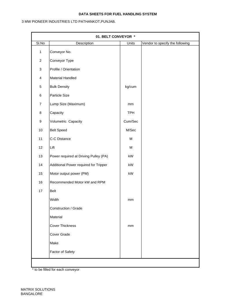
3 MW PIONEER INDUSTRIES LTD PATHANKOT,PUNJAB.
DATA SHEETS FOR FUEL HANDLING SYSTEM
Sl.No Units Vendor to specify the following
1 Conveyor No.
2 Conveyor Type
3 Profile / Orientation
4 Material Handled
5 Bulk Density kg/cum
6 Particle Size
7 Lump Size (Maximum) mm
8 Capacity TPH
9 Volumetric Capacity Cum/Sec
10 Belt Speed M/Sec
11 C-C Distance M
12 Lift M
13 Power required at Driving Pulley (PA) kW
14 Additional Power required for Tripper kW
15 Motor output power (PM) kW
16 Recommended Motor kW and RPM
17 Belt
Width mm
Construction / Grade
Material
Cover Thickness mm
Cover Grade
Make
Factor of Safety
* to be filled for each conveyor
01. BELT CONVEYOR *
Description
MATRIX SOLUTIONSBANGALORE
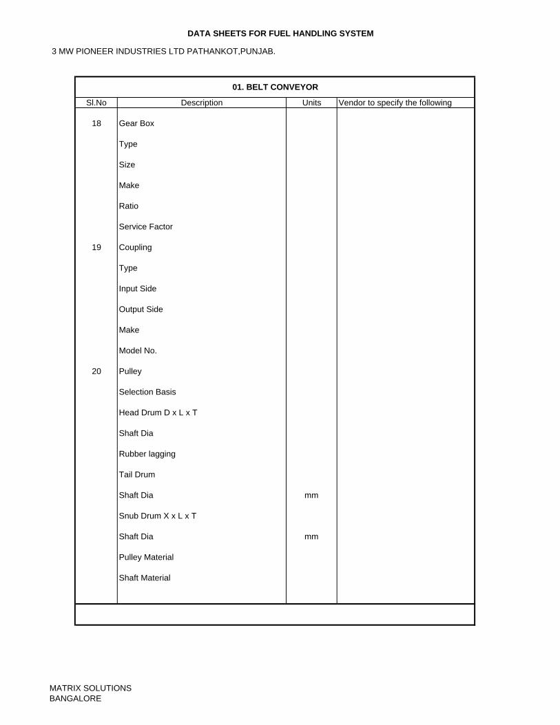
3 MW PIONEER INDUSTRIES LTD PATHANKOT,PUNJAB.
DATA SHEETS FOR FUEL HANDLING SYSTEM
Sl.No Units Vendor to specify the following
18 Gear Box
Type
Size
Make
Ratio
Service Factor
19 Coupling
Type
Input Side
Output Side
Make
Model No.
20 Pulley
Selection Basis
Head Drum D x L x T
Shaft Dia
Rubber lagging
Tail Drum
Shaft Dia mm
Snub Drum X x L x T
Shaft Dia mm
Pulley Material
Shaft Material
01. BELT CONVEYOR
Description
MATRIX SOLUTIONSBANGALORE
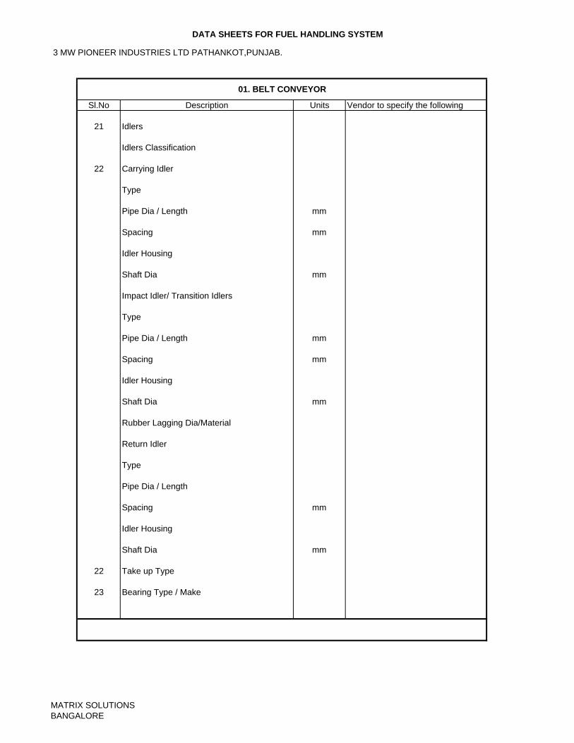
3 MW PIONEER INDUSTRIES LTD PATHANKOT,PUNJAB.
DATA SHEETS FOR FUEL HANDLING SYSTEM
Sl.No Units Vendor to specify the following
21 Idlers
Idlers Classification
22 Carrying Idler
Type
Pipe Dia / Length mm
Spacing mm
Idler Housing
Shaft Dia mm
Impact Idler/ Transition Idlers
Type
Pipe Dia / Length mm
Spacing mm
Idler Housing
Shaft Dia mm
Rubber Lagging Dia/Material
Return Idler
Type
Pipe Dia / Length
Spacing mm
Idler Housing
Shaft Dia mm
22 Take up Type
23 Bearing Type / Make
01. BELT CONVEYOR
Description
MATRIX SOLUTIONSBANGALORE
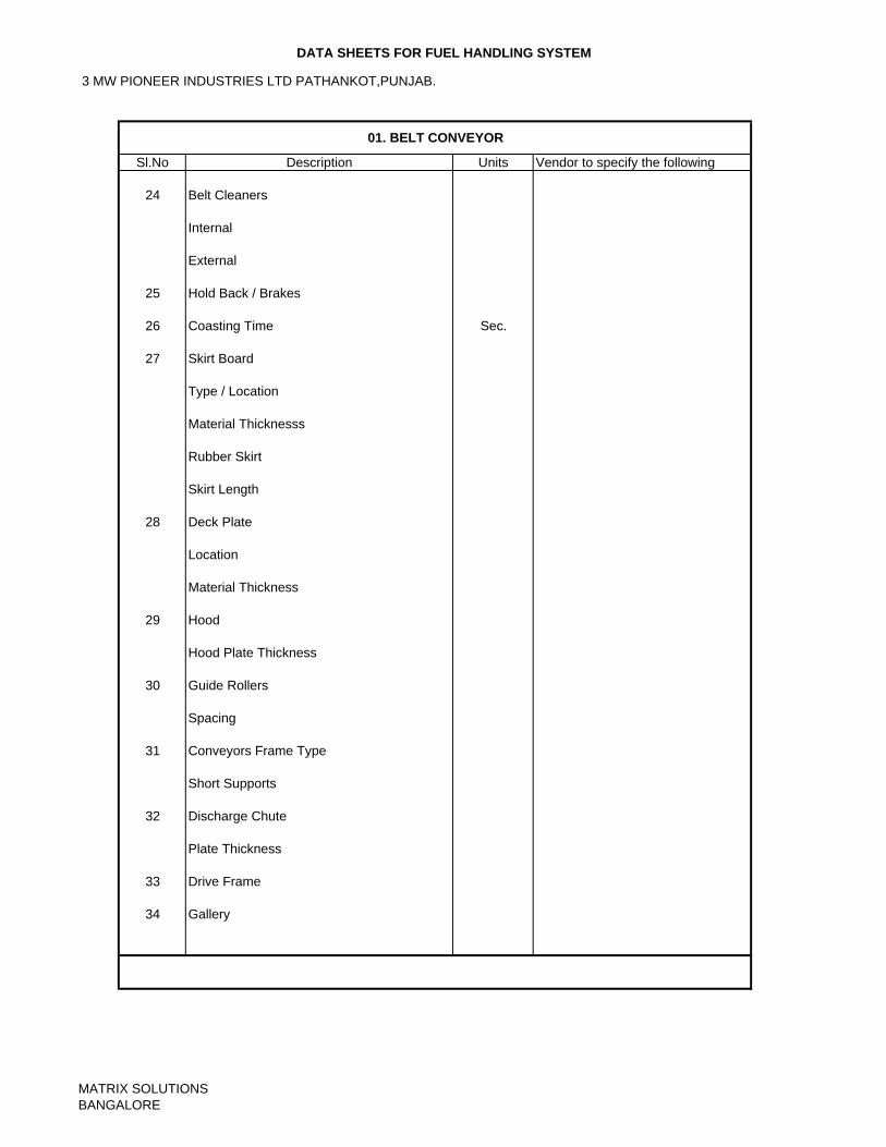
3 MW PIONEER INDUSTRIES LTD PATHANKOT,PUNJAB.
DATA SHEETS FOR FUEL HANDLING SYSTEM
Sl.No Units Vendor to specify the following
24 Belt Cleaners
Internal
External
25 Hold Back / Brakes
26 Coasting Time Sec.
27 Skirt Board
Type / Location
Material Thicknesss
Rubber Skirt
Skirt Length
28 Deck Plate
Location
Material Thickness
29 Hood
Hood Plate Thickness
30 Guide Rollers
Spacing
31 Conveyors Frame Type
Short Supports
32 Discharge Chute
Plate Thickness
33 Drive Frame
34 Gallery
01. BELT CONVEYOR
Description
MATRIX SOLUTIONSBANGALORE
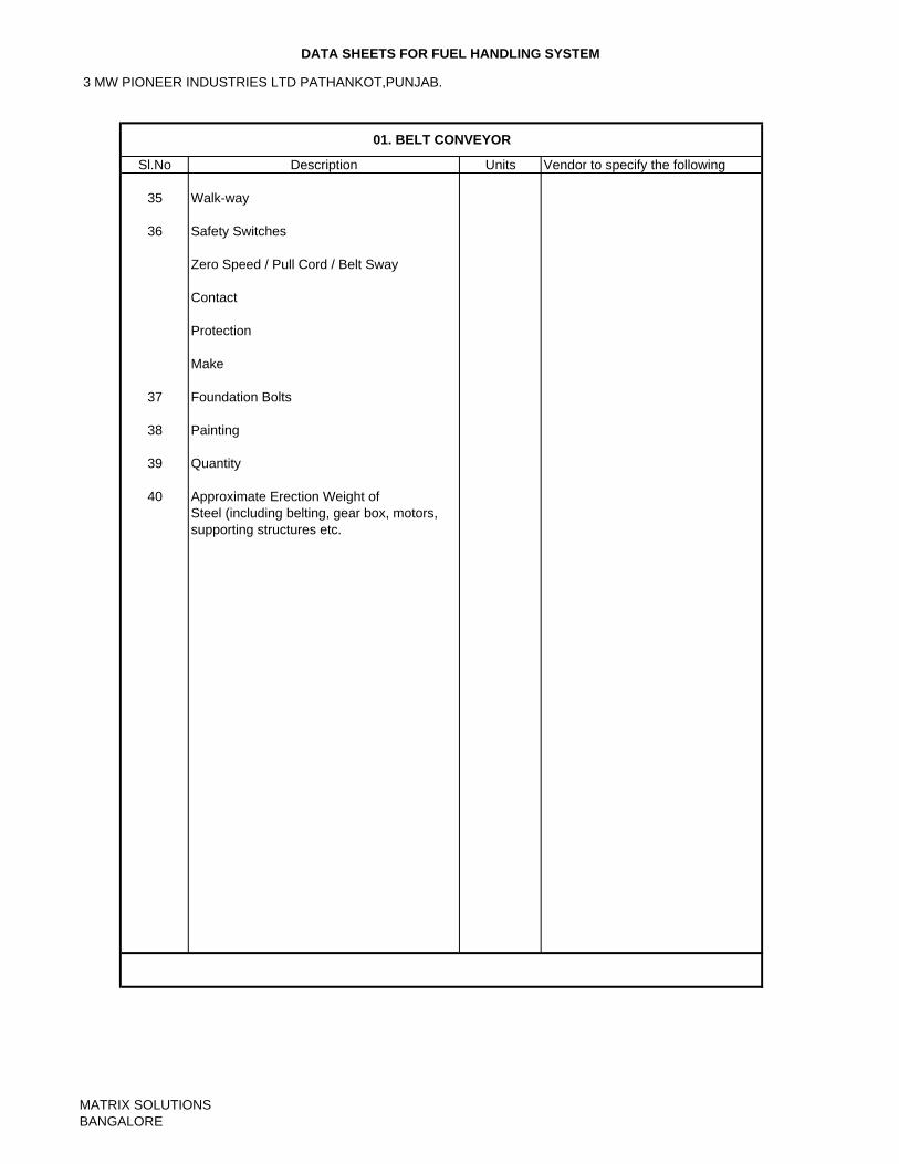
3 MW PIONEER INDUSTRIES LTD PATHANKOT,PUNJAB.
DATA SHEETS FOR FUEL HANDLING SYSTEM
Sl.No Units Vendor to specify the following
35 Walk-way
36 Safety Switches
Zero Speed / Pull Cord / Belt Sway
Contact
Protection
Make
37 Foundation Bolts
38 Painting
39 Quantity
40 Approximate Erection Weight ofSteel (including belting, gear box, motors,supporting structures etc.
01. BELT CONVEYOR
Description
MATRIX SOLUTIONSBANGALORE
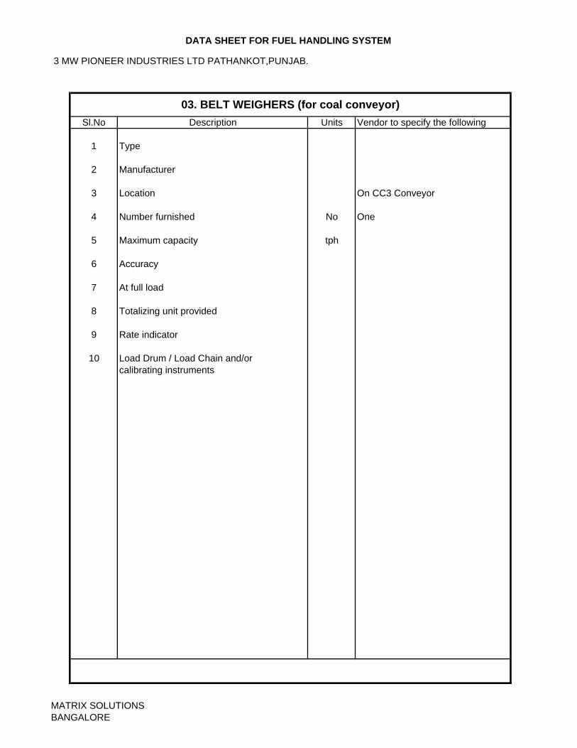
3 MW PIONEER INDUSTRIES LTD PATHANKOT,PUNJAB.
DATA SHEET FOR FUEL HANDLING SYSTEM
Sl.No Units Vendor to specify the following
1 Type
2 Manufacturer
3 Location On CC3 Conveyor
4 Number furnished No One
5 Maximum capacity tph
6 Accuracy
7 At full load
8 Totalizing unit provided
9 Rate indicator
10 Load Drum / Load Chain and/orcalibrating instruments
03. BELT WEIGHERS (for coal conveyor)Description
MATRIX SOLUTIONSBANGALORE
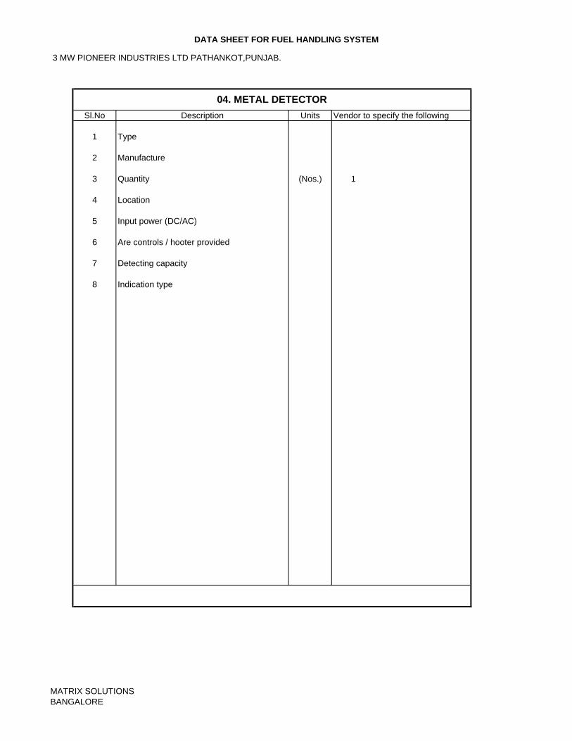
3 MW PIONEER INDUSTRIES LTD PATHANKOT,PUNJAB.
DATA SHEET FOR FUEL HANDLING SYSTEM
Sl.No Units Vendor to specify the following
1 Type
2 Manufacture
3 Quantity (Nos.) 1
4 Location
5 Input power (DC/AC)
6 Are controls / hooter provided
7 Detecting capacity
8 Indication type
04. METAL DETECTORDescription
MATRIX SOLUTIONSBANGALORE
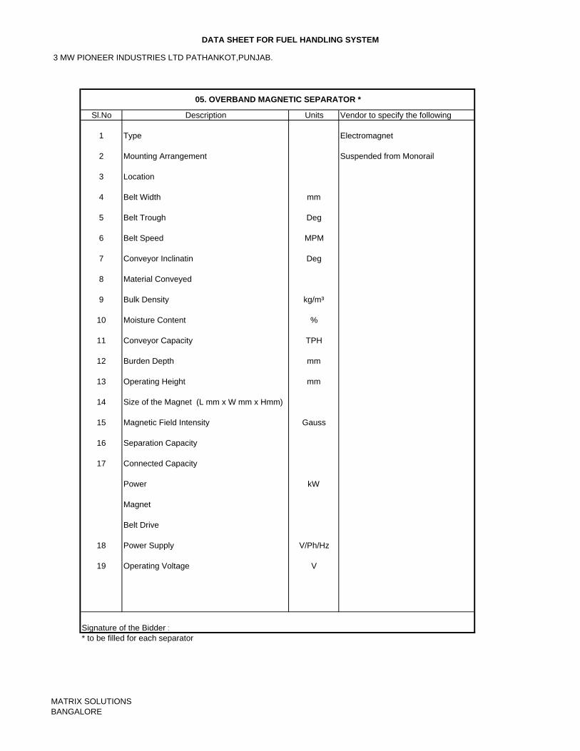
3 MW PIONEER INDUSTRIES LTD PATHANKOT,PUNJAB.
DATA SHEET FOR FUEL HANDLING SYSTEM
Sl.No Units Vendor to specify the following
1 Type Electromagnet
2 Mounting Arrangement Suspended from Monorail
3 Location
4 Belt Width mm
5 Belt Trough Deg
6 Belt Speed MPM
7 Conveyor Inclinatin Deg
8 Material Conveyed
9 Bulk Density kg/m³
10 Moisture Content %
11 Conveyor Capacity TPH
12 Burden Depth mm
13 Operating Height mm
14 Size of the Magnet (L mm x W mm x Hmm)
15 Magnetic Field Intensity Gauss
16 Separation Capacity
17 Connected Capacity
Power kW
Magnet
Belt Drive
18 Power Supply V/Ph/Hz
19 Operating Voltage V
* to be filled for each separator
05. OVERBAND MAGNETIC SEPARATOR *
Description
Signature of the Bidder :
MATRIX SOLUTIONSBANGALORE
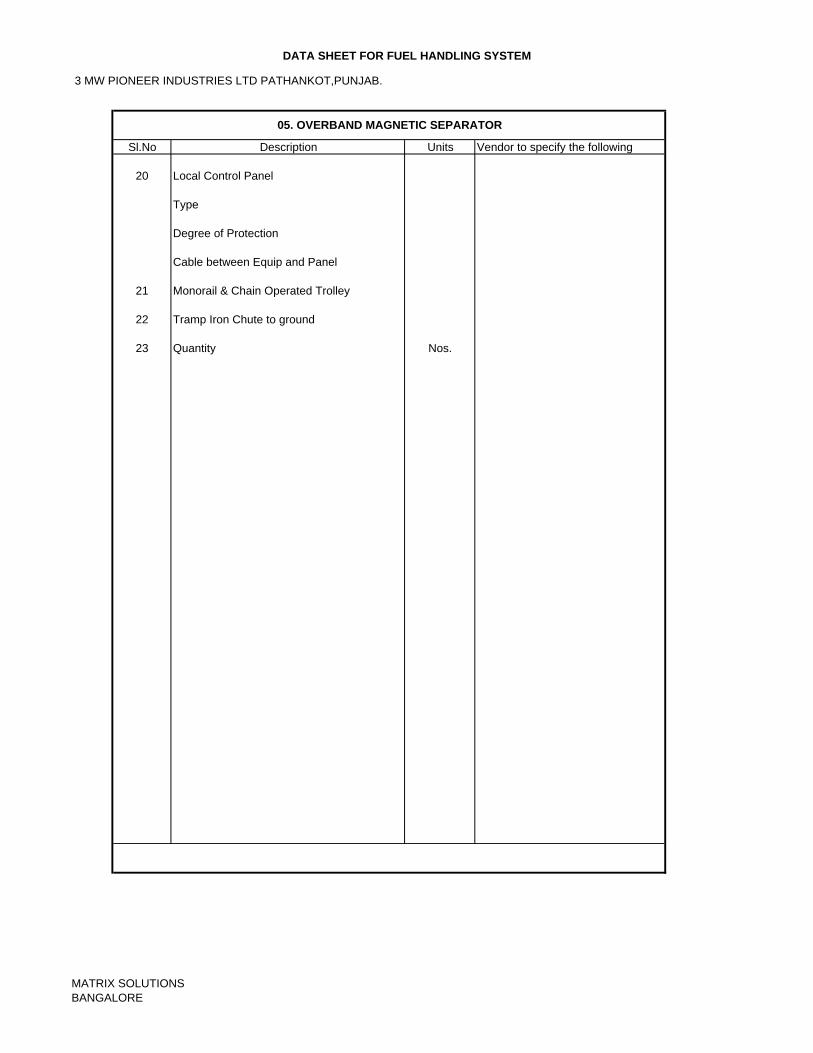
3 MW PIONEER INDUSTRIES LTD PATHANKOT,PUNJAB.
DATA SHEET FOR FUEL HANDLING SYSTEM
Sl.No Units Vendor to specify the following
20 Local Control Panel
Type
Degree of Protection
Cable between Equip and Panel
21 Monorail & Chain Operated Trolley
22 Tramp Iron Chute to ground
23 Quantity Nos.
05. OVERBAND MAGNETIC SEPARATOR
Description
MATRIX SOLUTIONSBANGALORE
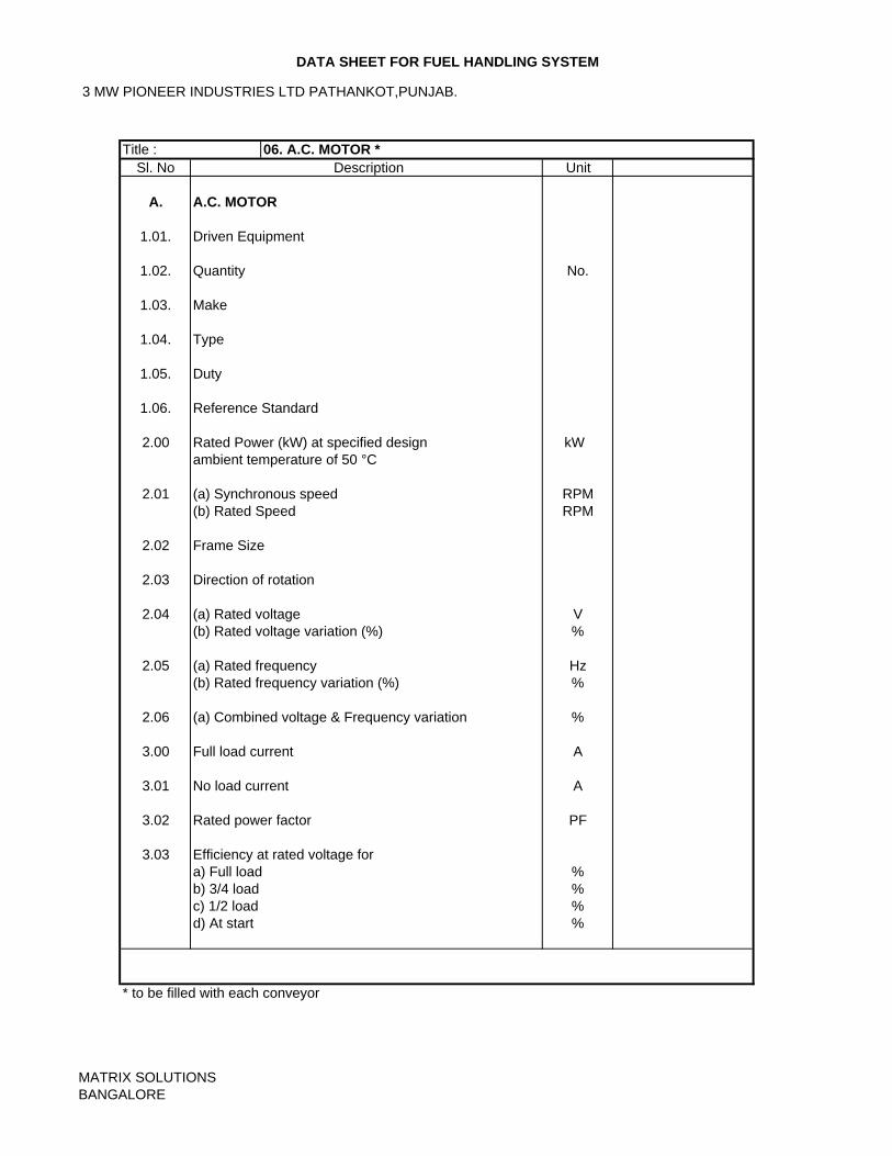
3 MW PIONEER INDUSTRIES LTD PATHANKOT,PUNJAB.
DATA SHEET FOR FUEL HANDLING SYSTEM
Sl. No Description Unit
A. A.C. MOTOR
1.01. Driven Equipment
1.02. Quantity No.
1.03. Make
1.04. Type
1.05. Duty
1.06. Reference Standard
2.00 Rated Power (kW) at specified design kWambient temperature of 50 °C
2.01 (a) Synchronous speed RPM(b) Rated Speed RPM
2.02 Frame Size
2.03 Direction of rotation
2.04 (a) Rated voltage V(b) Rated voltage variation (%) %
2.05 (a) Rated frequency Hz(b) Rated frequency variation (%) %
2.06 (a) Combined voltage & Frequency variation %
3.00 Full load current A
3.01 No load current A
3.02 Rated power factor PF
3.03 Efficiency at rated voltage fora) Full load %b) 3/4 load %c) 1/2 load %d) At start %
* to be filled with each conveyor
Title : 06. A.C. MOTOR *
MATRIX SOLUTIONSBANGALORE
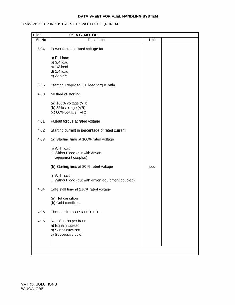
3 MW PIONEER INDUSTRIES LTD PATHANKOT,PUNJAB.
DATA SHEET FOR FUEL HANDLING SYSTEM
Sl. No Description Unit
3.04 Power factor at rated voltage for
a) Full loadb) 3/4 load c) 1/2 loadd) 1/4 loade) At start
3.05 Starting Torque to Full load torque ratio
4.00 Method of starting
(a) 100% voltage (VR)(b) 85% voltage (VR)(c) 80% voltage (VR)
4.01 Pullout torque at rated voltage
4.02 Starting current in percentage of rated current
4.03 (a) Starting time at 100% rated voltage
i) With load ii) Without load (but with driven equipment coupled)
(b) Starting time at 80 % rated voltage sec
i) With load ii) Without load (but with driven equipment coupled)
4.04 Safe stall time at 110% rated voltage
(a) Hot condition(b) Cold condition
4.05 Thermal time constant, in min.
4.06 No. of starts per houra) Equally spreadb) Successive hotc) Successive cold
Title : 06. A.C. MOTOR
MATRIX SOLUTIONSBANGALORE
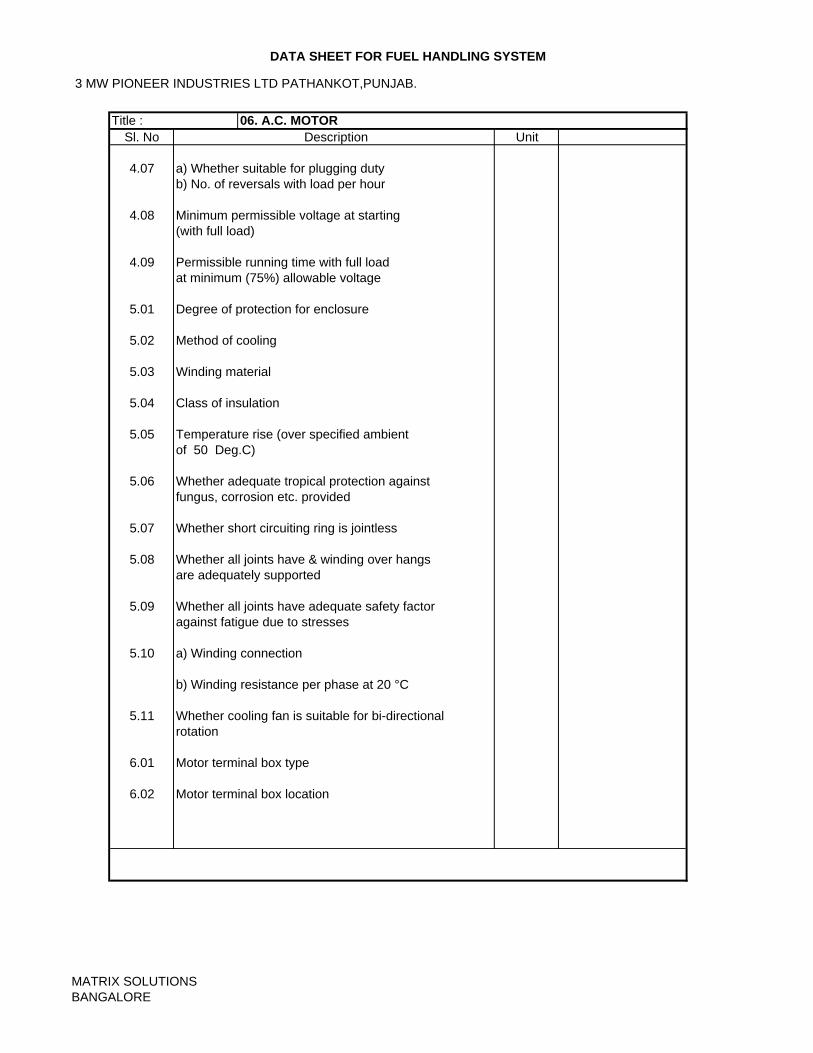
3 MW PIONEER INDUSTRIES LTD PATHANKOT,PUNJAB.
DATA SHEET FOR FUEL HANDLING SYSTEM
Sl. No Description Unit
4.07 a) Whether suitable for plugging duty b) No. of reversals with load per hour
4.08 Minimum permissible voltage at starting(with full load)
4.09 Permissible running time with full loadat minimum (75%) allowable voltage
5.01 Degree of protection for enclosure
5.02 Method of cooling
5.03 Winding material
5.04 Class of insulation
5.05 Temperature rise (over specified ambientof 50 Deg.C)
5.06 Whether adequate tropical protection againstfungus, corrosion etc. provided
5.07 Whether short circuiting ring is jointless
5.08 Whether all joints have & winding over hangsare adequately supported
5.09 Whether all joints have adequate safety factoragainst fatigue due to stresses
5.10 a) Winding connection
b) Winding resistance per phase at 20 °C
5.11 Whether cooling fan is suitable for bi-directionalrotation
6.01 Motor terminal box type
6.02 Motor terminal box location
Title : 06. A.C. MOTOR
MATRIX SOLUTIONSBANGALORE
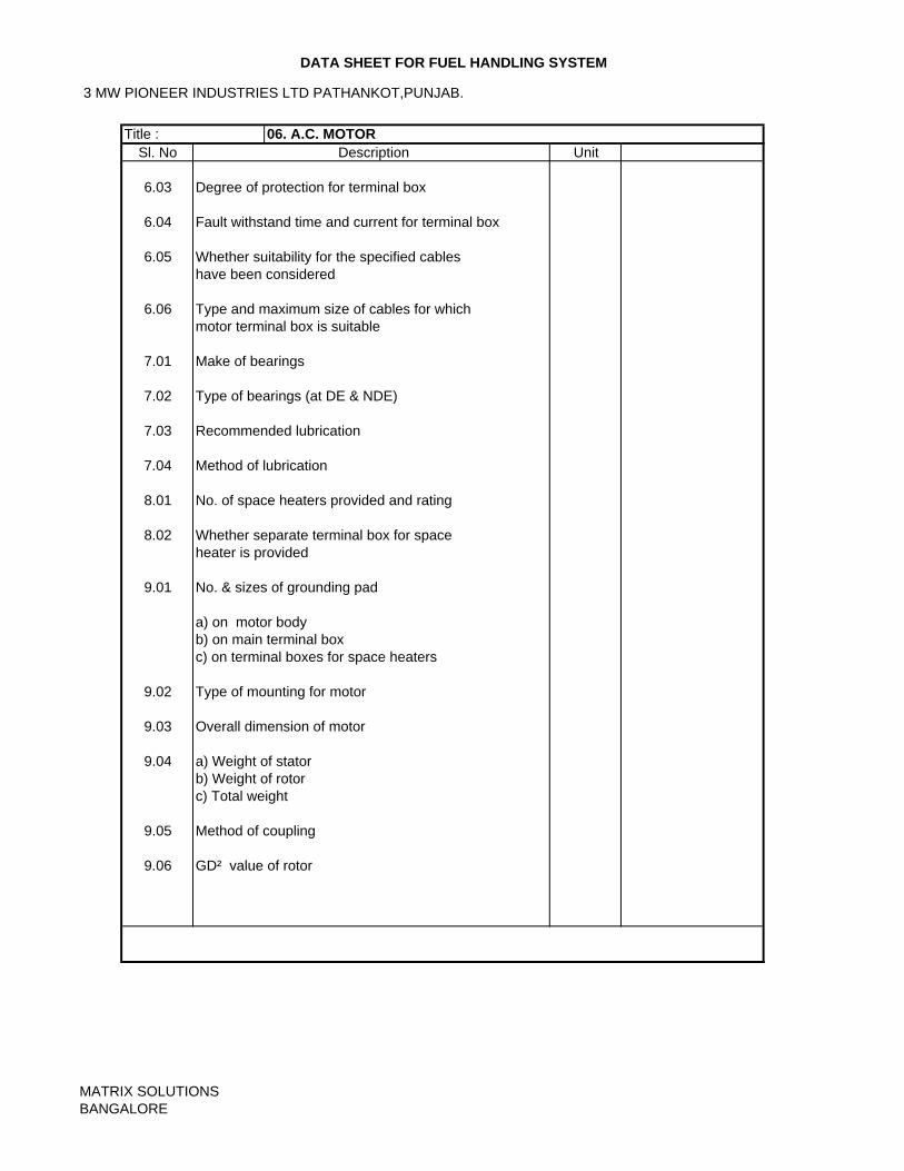
3 MW PIONEER INDUSTRIES LTD PATHANKOT,PUNJAB.
DATA SHEET FOR FUEL HANDLING SYSTEM
Sl. No Description Unit
6.03 Degree of protection for terminal box
6.04 Fault withstand time and current for terminal box
6.05 Whether suitability for the specified cableshave been considered
6.06 Type and maximum size of cables for whichmotor terminal box is suitable
7.01 Make of bearings
7.02 Type of bearings (at DE & NDE)
7.03 Recommended lubrication
7.04 Method of lubrication
8.01 No. of space heaters provided and rating
8.02 Whether separate terminal box for spaceheater is provided
9.01 No. & sizes of grounding pad
a) on motor bodyb) on main terminal boxc) on terminal boxes for space heaters
9.02 Type of mounting for motor
9.03 Overall dimension of motor
9.04 a) Weight of statorb) Weight of rotorc) Total weight
9.05 Method of coupling
9.06 GD² value of rotor
Title : 06. A.C. MOTOR
MATRIX SOLUTIONSBANGALORE
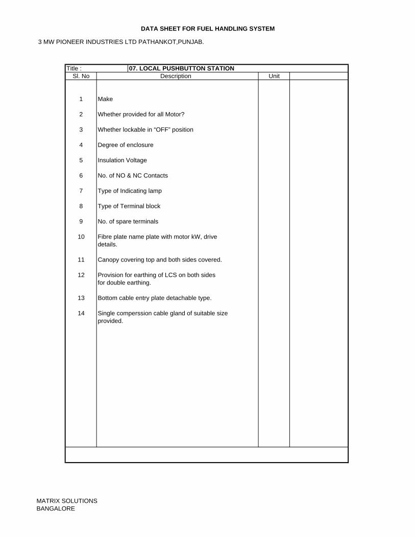
3 MW PIONEER INDUSTRIES LTD PATHANKOT,PUNJAB.
DATA SHEET FOR FUEL HANDLING SYSTEM
Sl. No Description Unit
1 Make
2 Whether provided for all Motor?
3 Whether lockable in “OFF” position
4 Degree of enclosure
5 Insulation Voltage
6 No. of NO & NC Contacts
7 Type of Indicating lamp
8 Type of Terminal block
9 No. of spare terminals
10 Fibre plate name plate with motor kW, drivedetails.
11 Canopy covering top and both sides covered.
12 Provision for earthing of LCS on both sidesfor double earthing.
13 Bottom cable entry plate detachable type.
14 Single comperssion cable gland of suitable sizeprovided.
Title : 07. LOCAL PUSHBUTTON STATION
MATRIX SOLUTIONSBANGALORE
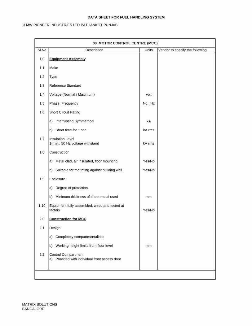
3 MW PIONEER INDUSTRIES LTD PATHANKOT,PUNJAB.
DATA SHEET FOR FUEL HANDLING SYSTEM
Sl.No Description Units Vendor to specify the following
1.0 Equipment Assembly
1.1 Make
1.2 Type
1.3 Reference Standard
1.4 Voltage (Normal / Maximum) volt
1.5 Phase, Frequency No., Hz
1.6 Short Circuit Rating
a) Interrupting Symmetrical kA
b) Short time for 1 sec. kA rms
1.7 Insulation Level1-min., 50 Hz voltage withstand kV rms
1.8 Construction
a) Metal clad, air insulated, floor mounting Yes/No
b) Suitable for mounting against building wall Yes/No
1.9 Enclosure
a) Degree of protection
b) Minimum thickness of sheet metal used mm
1.10 Equipment fully assembled, wired and tested atfactory Yes/No
2.0 Construction for MCC
2.1 Design
a) Completely compartmentalised
b) Working height limits from floor level mm
2.2 Control Compartmenta) Provided with individual front access door
08. MOTOR CONTROL CENTRE (MCC)
MATRIX SOLUTIONSBANGALORE
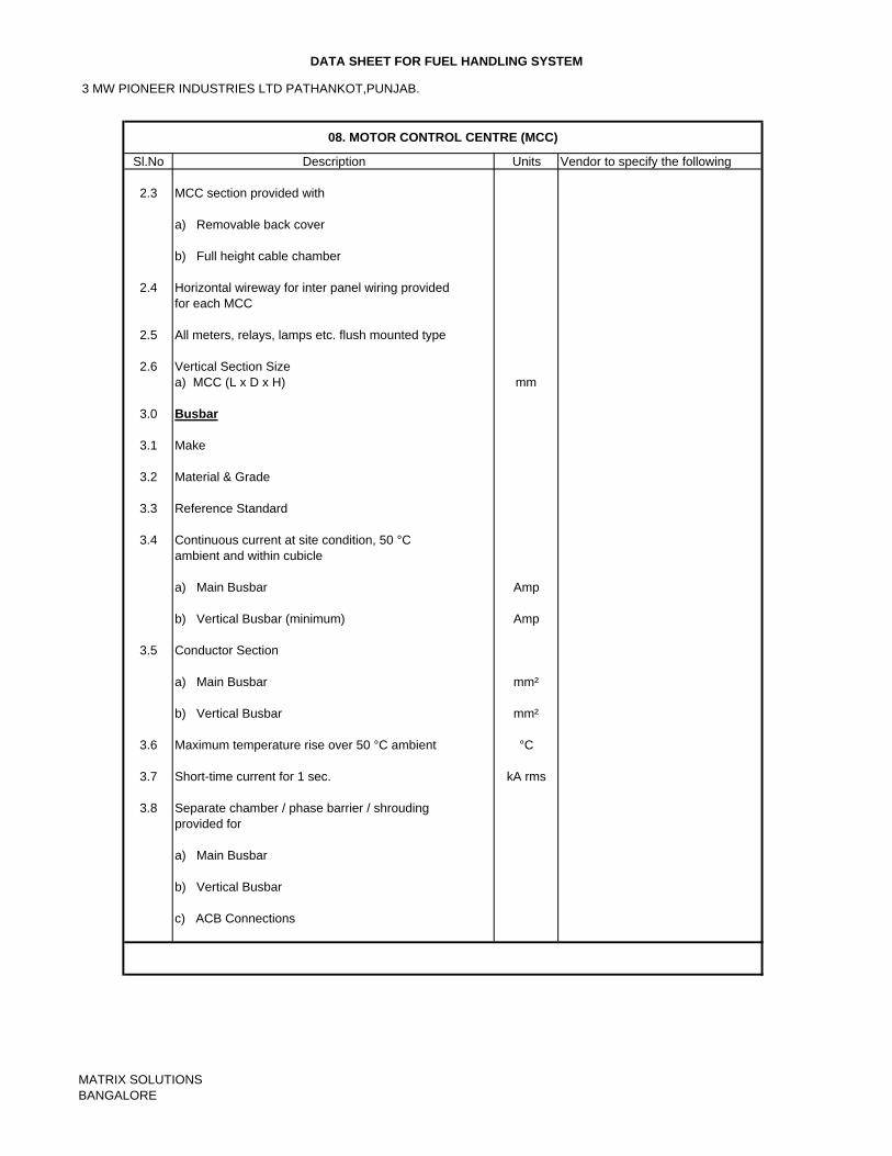
3 MW PIONEER INDUSTRIES LTD PATHANKOT,PUNJAB.
DATA SHEET FOR FUEL HANDLING SYSTEM
Sl.No Description Units Vendor to specify the following
2.3 MCC section provided with
a) Removable back cover
b) Full height cable chamber
2.4 Horizontal wireway for inter panel wiring providedfor each MCC
2.5 All meters, relays, lamps etc. flush mounted type
2.6 Vertical Section Sizea) MCC (L x D x H) mm
3.0 Busbar
3.1 Make
3.2 Material & Grade
3.3 Reference Standard
3.4 Continuous current at site condition, 50 °C ambient and within cubicle
a) Main Busbar Amp
b) Vertical Busbar (minimum) Amp
3.5 Conductor Section
a) Main Busbar mm²
b) Vertical Busbar mm²
3.6 Maximum temperature rise over 50 °C ambient °C
3.7 Short-time current for 1 sec. kA rms
3.8 Separate chamber / phase barrier / shroudingprovided for
a) Main Busbar
b) Vertical Busbar
c) ACB Connections
08. MOTOR CONTROL CENTRE (MCC)
MATRIX SOLUTIONSBANGALORE
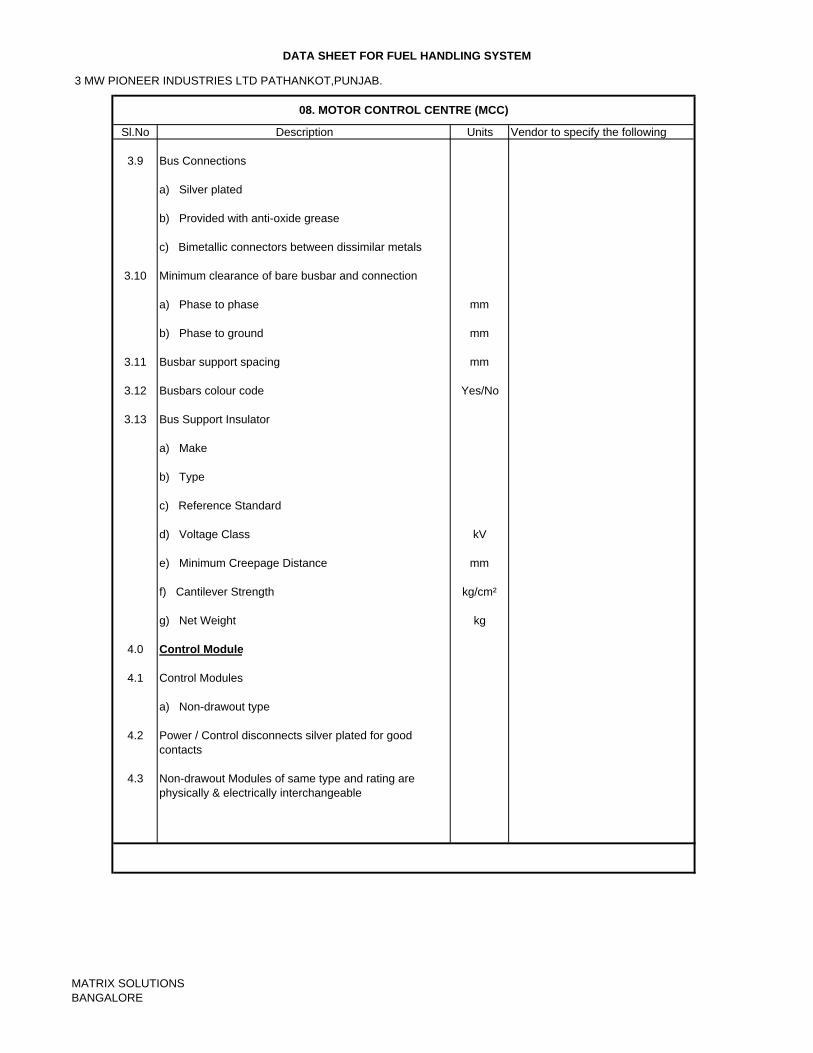
3 MW PIONEER INDUSTRIES LTD PATHANKOT,PUNJAB.
DATA SHEET FOR FUEL HANDLING SYSTEM
Sl.No Description Units Vendor to specify the following
3.9 Bus Connections
a) Silver plated
b) Provided with anti-oxide grease
c) Bimetallic connectors between dissimilar metals
3.10 Minimum clearance of bare busbar and connection
a) Phase to phase mm
b) Phase to ground mm
3.11 Busbar support spacing mm
3.12 Busbars colour code Yes/No
3.13 Bus Support Insulator
a) Make
b) Type
c) Reference Standard
d) Voltage Class kV
e) Minimum Creepage Distance mm
f) Cantilever Strength kg/cm²
g) Net Weight kg
4.0 Control Module
4.1 Control Modules
a) Non-drawout type
4.2 Power / Control disconnects silver plated for goodcontacts
4.3 Non-drawout Modules of same type and rating are physically & electrically interchangeable
08. MOTOR CONTROL CENTRE (MCC)
MATRIX SOLUTIONSBANGALORE
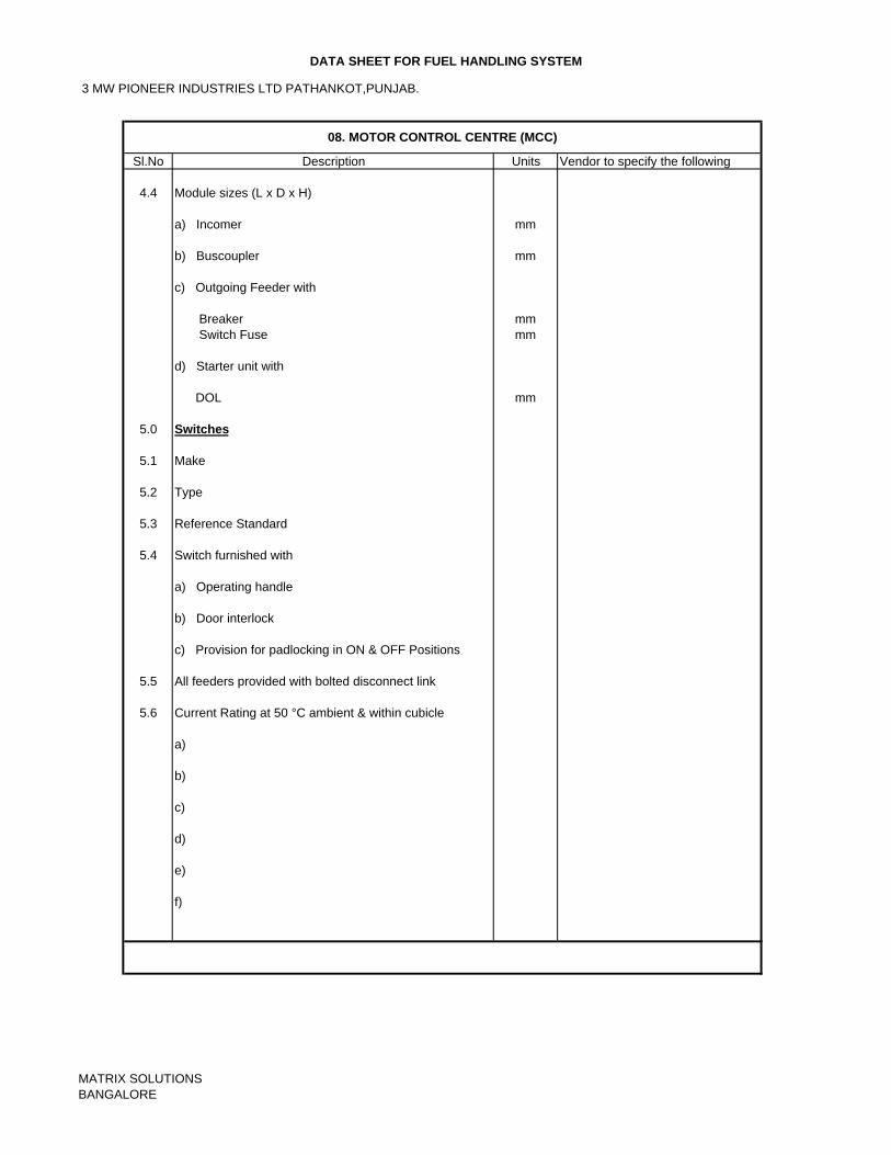
3 MW PIONEER INDUSTRIES LTD PATHANKOT,PUNJAB.
DATA SHEET FOR FUEL HANDLING SYSTEM
Sl.No Description Units Vendor to specify the following
4.4 Module sizes (L x D x H)
a) Incomer mm
b) Buscoupler mm
c) Outgoing Feeder with
Breaker mm Switch Fuse mm
d) Starter unit with DOL mm
5.0 Switches
5.1 Make
5.2 Type
5.3 Reference Standard
5.4 Switch furnished with
a) Operating handle
b) Door interlock
c) Provision for padlocking in ON & OFF Positions
5.5 All feeders provided with bolted disconnect link
5.6 Current Rating at 50 °C ambient & within cubicle
a)
b)
c)
d)
e)
f)
08. MOTOR CONTROL CENTRE (MCC)
MATRIX SOLUTIONSBANGALORE
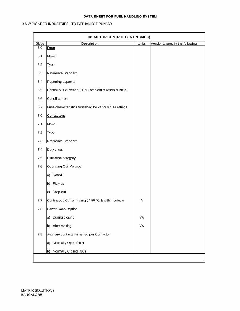
3 MW PIONEER INDUSTRIES LTD PATHANKOT,PUNJAB.
DATA SHEET FOR FUEL HANDLING SYSTEM
Sl.No Description Units Vendor to specify the following6.0 Fuse
6.1 Make
6.2 Type
6.3 Reference Standard
6.4 Rupturing capacity
6.5 Continuous current at 50 °C ambient & within cubicle
6.6 Cut off current
6.7 Fuse characteristics furnished for various fuse ratings
7.0 Contactors
7.1 Make
7.2 Type
7.3 Reference Standard
7.4 Duty class
7.5 Utilization category
7.6 Operating Coil Voltage
a) Rated
b) Pick-up
c) Drop-out
7.7 Continuous Current rating @ 50 °C & within cubicle A
7.8 Power Consumption
a) During closing VA
b) After closing VA
7.9 Auxiliary contacts furnished per Contactor
a) Normally Open (NO)
b) Normally Closed (NC)
08. MOTOR CONTROL CENTRE (MCC)
MATRIX SOLUTIONSBANGALORE
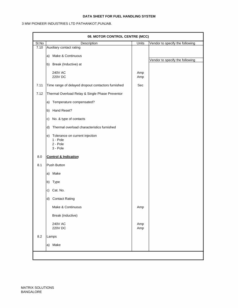
3 MW PIONEER INDUSTRIES LTD PATHANKOT,PUNJAB.
DATA SHEET FOR FUEL HANDLING SYSTEM
Sl.No Description Units Vendor to specify the following7.10 Auxiliary contact rating
a) Make & Continuous Vendor to specify the following
b) Break (Inductive) at
240V AC Amp 220V DC Amp
7.11 Time range of delayed dropout contactors furnished Sec
7.12 Thermal Overload Relay & Single Phase Preventor
a) Temperature compensated?
b) Hand Reset?
c) No. & type of contacts
d) Thermal overload characteristics furnished
e) Tolerance on current injection 1 - Pole 2 - Pole 3 - Pole
8.0 Control & Indication
8.1 Push Button
a) Make
b) Type
c) Cat. No.
d) Contact Rating
Make & Continuous Amp
Break (inductive)
240V AC Amp 220V DC Amp
8.2 Lamps
a) Make
08. MOTOR CONTROL CENTRE (MCC)
MATRIX SOLUTIONSBANGALORE
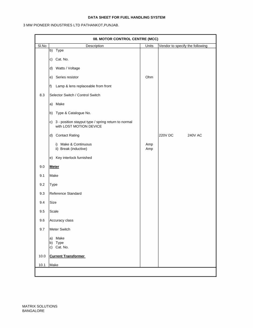
3 MW PIONEER INDUSTRIES LTD PATHANKOT,PUNJAB.
DATA SHEET FOR FUEL HANDLING SYSTEM
Sl.No Description Units Vendor to specify the followingb) Type
c) Cat. No.
d) Watts / Voltage
e) Series resistor Ohm
f) Lamp & lens replaceable from front
8.3 Selector Switch / Control Switch
a) Make
b) Type & Catalogue No.
c) 3 - position stayput type / spring return to normal with LOST MOTION DEVICE
d) Contact Rating 220V DC 240V AC
i) Make & Continuous Amp ii) Break (inductive) Amp
e) Key interlock furnished
9.0 Meter
9.1 Make
9.2 Type
9.3 Reference Standard
9.4 Size
9.5 Scale
9.6 Accuracy class
9.7 Meter Switch
a) Makeb) Typec) Cat. No.
10.0 Current Transformer
10.1 Make
08. MOTOR CONTROL CENTRE (MCC)
MATRIX SOLUTIONSBANGALORE
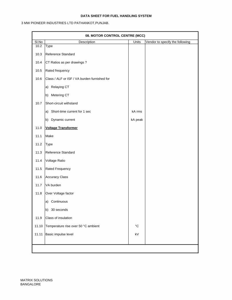
3 MW PIONEER INDUSTRIES LTD PATHANKOT,PUNJAB.
DATA SHEET FOR FUEL HANDLING SYSTEM
Sl.No Description Units Vendor to specify the following10.2 Type
10.3 Reference Standard
10.4 CT Ratios as per drawings ?
10.5 Rated frequency
10.6 Class / ALF or ISF / VA burden furnished for
a) Relaying CT
b) Metering CT
10.7 Short-circuit withstand
a) Short-time current for 1 sec kA rms
b) Dynamic current kA peak
11.0 Voltage Transformer
11.1 Make
11.2 Type
11.3 Reference Standard
11.4 Voltage Ratio
11.5 Rated Frequency
11.6 Accuracy Class
11.7 VA burden
11.8 Over Voltage factor
a) Continuous
b) 30 seconds
11.9 Class of insulation
11.10 Temperature rise over 50 °C ambient °C
11.11 Basic impulse level kV
08. MOTOR CONTROL CENTRE (MCC)
MATRIX SOLUTIONSBANGALORE
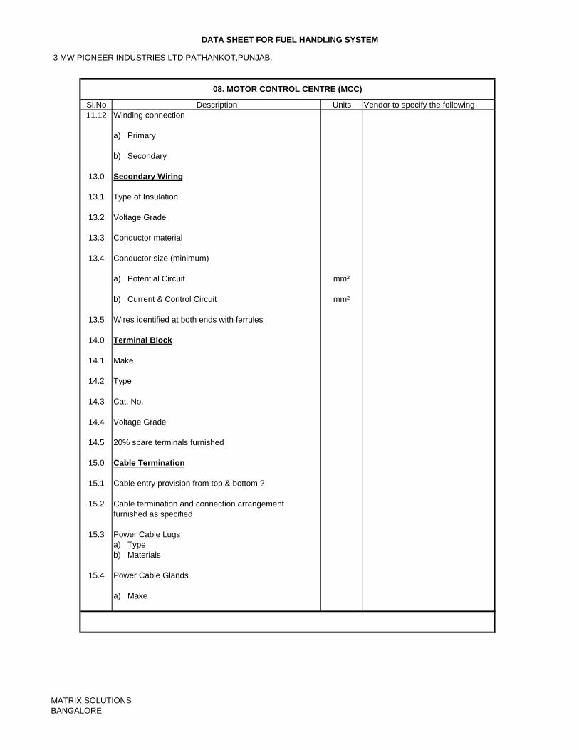
3 MW PIONEER INDUSTRIES LTD PATHANKOT,PUNJAB.
DATA SHEET FOR FUEL HANDLING SYSTEM
Sl.No Description Units Vendor to specify the following11.12 Winding connection
a) Primary
b) Secondary
13.0 Secondary Wiring
13.1 Type of Insulation
13.2 Voltage Grade
13.3 Conductor material
13.4 Conductor size (minimum)
a) Potential Circuit mm²
b) Current & Control Circuit mm²
13.5 Wires identified at both ends with ferrules
14.0 Terminal Block
14.1 Make
14.2 Type
14.3 Cat. No.
14.4 Voltage Grade
14.5 20% spare terminals furnished
15.0 Cable Termination
15.1 Cable entry provision from top & bottom ?
15.2 Cable termination and connection arrangementfurnished as specified
15.3 Power Cable Lugsa) Typeb) Materials
15.4 Power Cable Glands
a) Make
08. MOTOR CONTROL CENTRE (MCC)
MATRIX SOLUTIONSBANGALORE
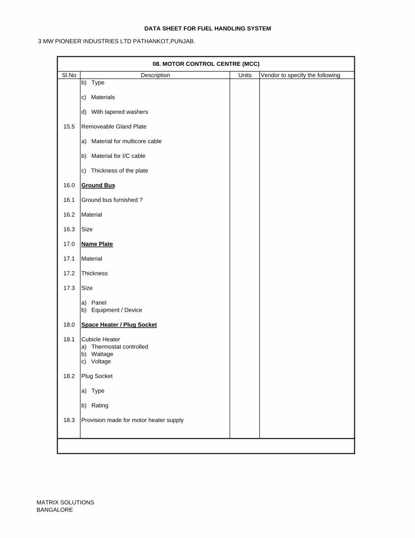
3 MW PIONEER INDUSTRIES LTD PATHANKOT,PUNJAB.
DATA SHEET FOR FUEL HANDLING SYSTEM
Sl.No Description Units Vendor to specify the followingb) Type
c) Materials
d) With tapered washers
15.5 Removeable Gland Plate
a) Material for multicore cable
b) Material for I/C cable
c) Thickness of the plate
16.0 Ground Bus
16.1 Ground bus furnished ?
16.2 Material
16.3 Size
17.0 Name Plate
17.1 Material
17.2 Thickness
17.3 Size
a) Panelb) Equipment / Device
18.0 Space Heater / Plug Socket
18.1 Cubicle Heatera) Thermostat controlledb) Wattagec) Voltage
18.2 Plug Socket
a) Type
b) Rating
18.3 Provision made for motor heater supply
08. MOTOR CONTROL CENTRE (MCC)
MATRIX SOLUTIONSBANGALORE
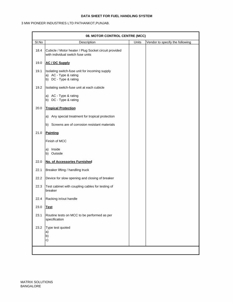
3 MW PIONEER INDUSTRIES LTD PATHANKOT,PUNJAB.
DATA SHEET FOR FUEL HANDLING SYSTEM
Sl.No Description Units Vendor to specify the following
18.4 Cubicle / Motor heater / Plug Socket circuit providedwith individual switch fuse units
19.0 AC / DC Supply
19.1 Isolating switch-fuse unit for incoming supplya) AC - Type & ratingb) DC - Type & rating
19.2 Isolating switch-fuse unit at each cubicle
a) AC - Type & ratingb) DC - Type & rating
20.0 Tropical Protection
a) Any special treatment for tropical protection
b) Screens are of corrosion resistant materials
21.0 Painting
Finish of MCC
a) Insideb) Outside
22.0 No. of Accessories Furnished
22.1 Breaker lifting / handling truck
22.2 Device for slow opening and closing of breaker
22.3 Test cabinet with coupling cables for testing of breaker
22.4 Racking in/out handle
23.0 Test
23.1 Routine tests on MCC to be performed as perspecification
23.2 Type test quoteda)b)c)
08. MOTOR CONTROL CENTRE (MCC)
MATRIX SOLUTIONSBANGALORE
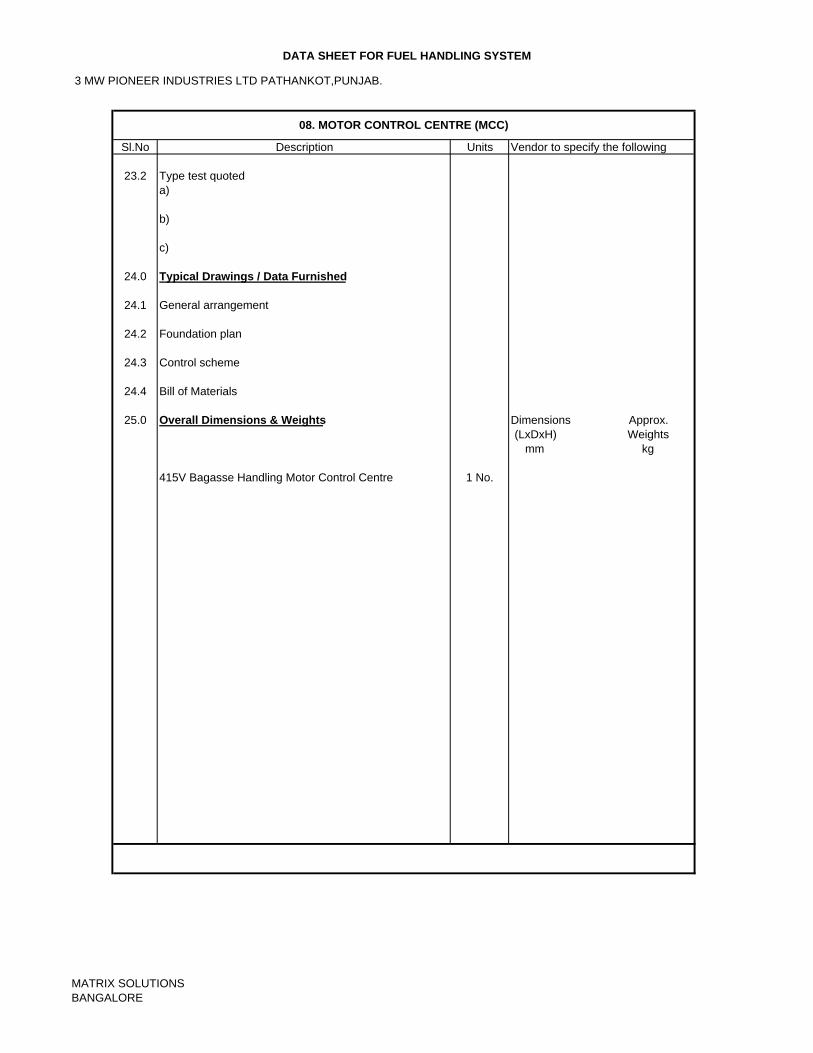
3 MW PIONEER INDUSTRIES LTD PATHANKOT,PUNJAB.
DATA SHEET FOR FUEL HANDLING SYSTEM
Sl.No Description Units Vendor to specify the following
23.2 Type test quoteda)
b)
c)
24.0 Typical Drawings / Data Furnished
24.1 General arrangement
24.2 Foundation plan
24.3 Control scheme
24.4 Bill of Materials
25.0 Overall Dimensions & Weights Dimensions Approx.(LxDxH) Weights
mm kg
415V Bagasse Handling Motor Control Centre 1 No.
08. MOTOR CONTROL CENTRE (MCC)
MATRIX SOLUTIONSBANGALORE
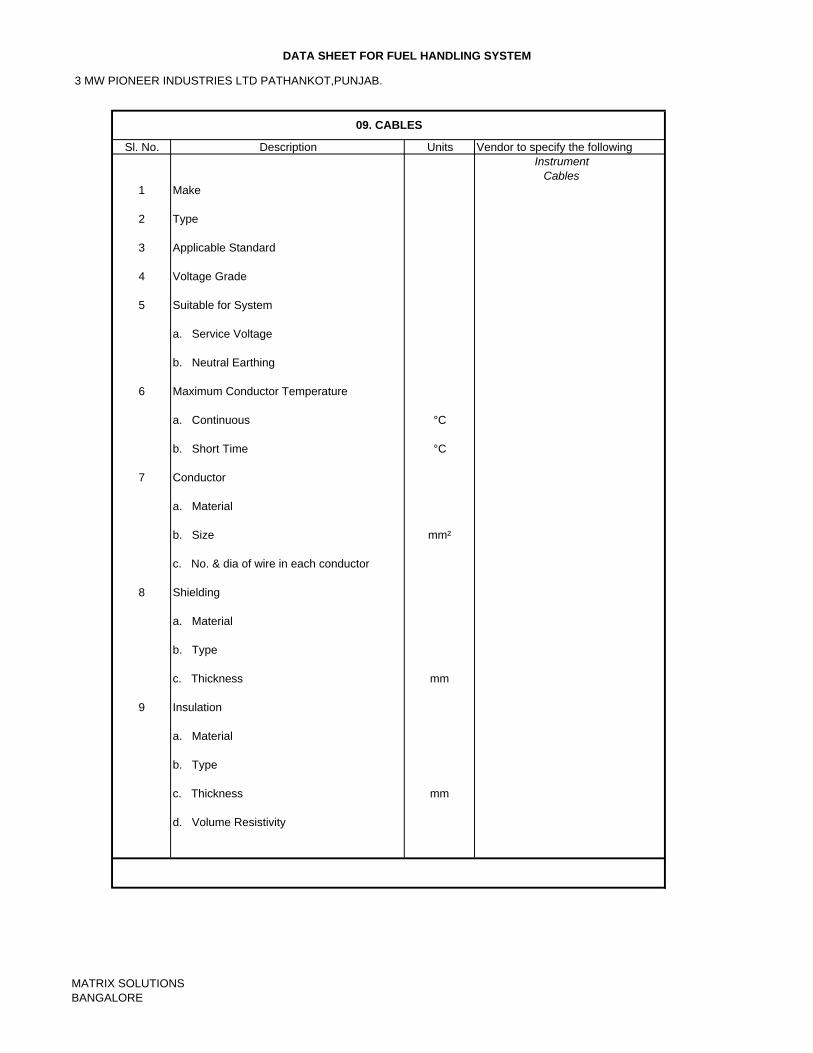
3 MW PIONEER INDUSTRIES LTD PATHANKOT,PUNJAB.
DATA SHEET FOR FUEL HANDLING SYSTEM
Sl. No. Units Vendor to specify the followingInstrument
Cables1 Make
2 Type
3 Applicable Standard
4 Voltage Grade
5 Suitable for System
a. Service Voltage
b. Neutral Earthing
6 Maximum Conductor Temperature
a. Continuous °C
b. Short Time °C
7 Conductor
a. Material
b. Size mm²
c. No. & dia of wire in each conductor
8 Shielding
a. Material
b. Type
c. Thickness mm
9 Insulation
a. Material
b. Type
c. Thickness mm
d. Volume Resistivity
09. CABLES
Description
MATRIX SOLUTIONSBANGALORE
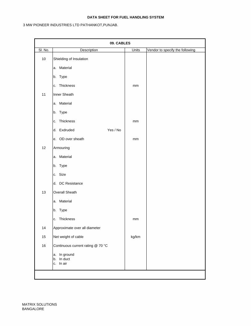
3 MW PIONEER INDUSTRIES LTD PATHANKOT,PUNJAB.
DATA SHEET FOR FUEL HANDLING SYSTEM
Sl. No. Units Vendor to specify the following
10 Shielding of Insulation
a. Material
b. Type
c. Thickness mm
11 Inner Sheath
a. Material
b. Type
c. Thickness mm
d. Exdruded Yes / No
e. OD over sheath mm
12 Armouring
a. Material
b. Type
c. Size
d. DC Resistance
13 Overall Sheath
a. Material
b. Type
c. Thickness mm
14 Approximate over all diameter
15 Net weight of cable kg/km
16 Continuous current rating @ 70 °C
a. In groundb. In ductc. In air
09. CABLES
Description
MATRIX SOLUTIONSBANGALORE
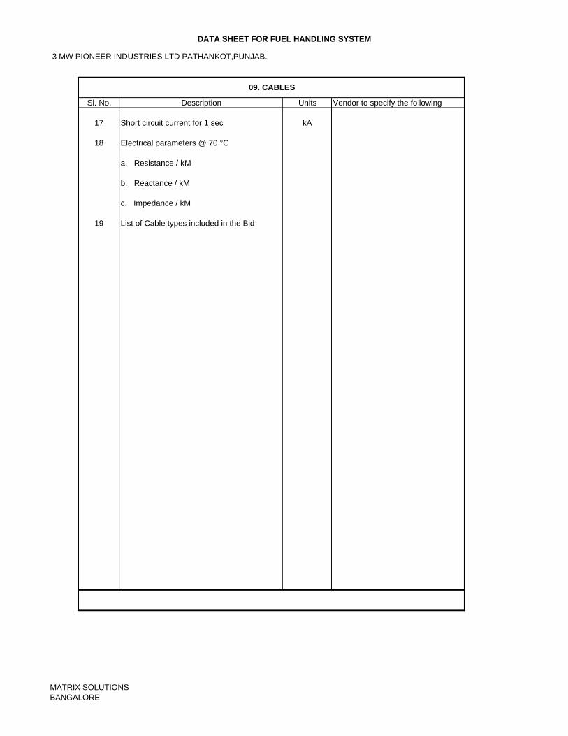
3 MW PIONEER INDUSTRIES LTD PATHANKOT,PUNJAB.
DATA SHEET FOR FUEL HANDLING SYSTEM
Sl. No. Units Vendor to specify the following
17 Short circuit current for 1 sec kA
18 Electrical parameters @ 70 °C
a. Resistance / kM
b. Reactance / kM
c. Impedance / kM
19 List of Cable types included in the Bid
09. CABLES
Description
MATRIX SOLUTIONSBANGALORE
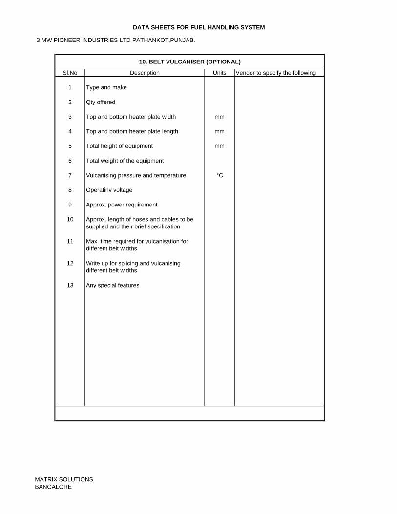
3 MW PIONEER INDUSTRIES LTD PATHANKOT,PUNJAB.
DATA SHEETS FOR FUEL HANDLING SYSTEM
Sl.No Units Vendor to specify the following
1 Type and make
2 Qty offered
3 Top and bottom heater plate width mm
4 Top and bottom heater plate length mm
5 Total height of equipment mm
6 Total weight of the equipment
7 Vulcanising pressure and temperature °C
8 Operatinv voltage
9 Approx. power requirement
10 Approx. length of hoses and cables to besupplied and their brief specification
11 Max. time required for vulcanisation fordifferent belt widths
12 Write up for splicing and vulcanising different belt widths
13 Any special features
10. BELT VULCANISER (OPTIONAL)
Description
MATRIX SOLUTIONSBANGALORE
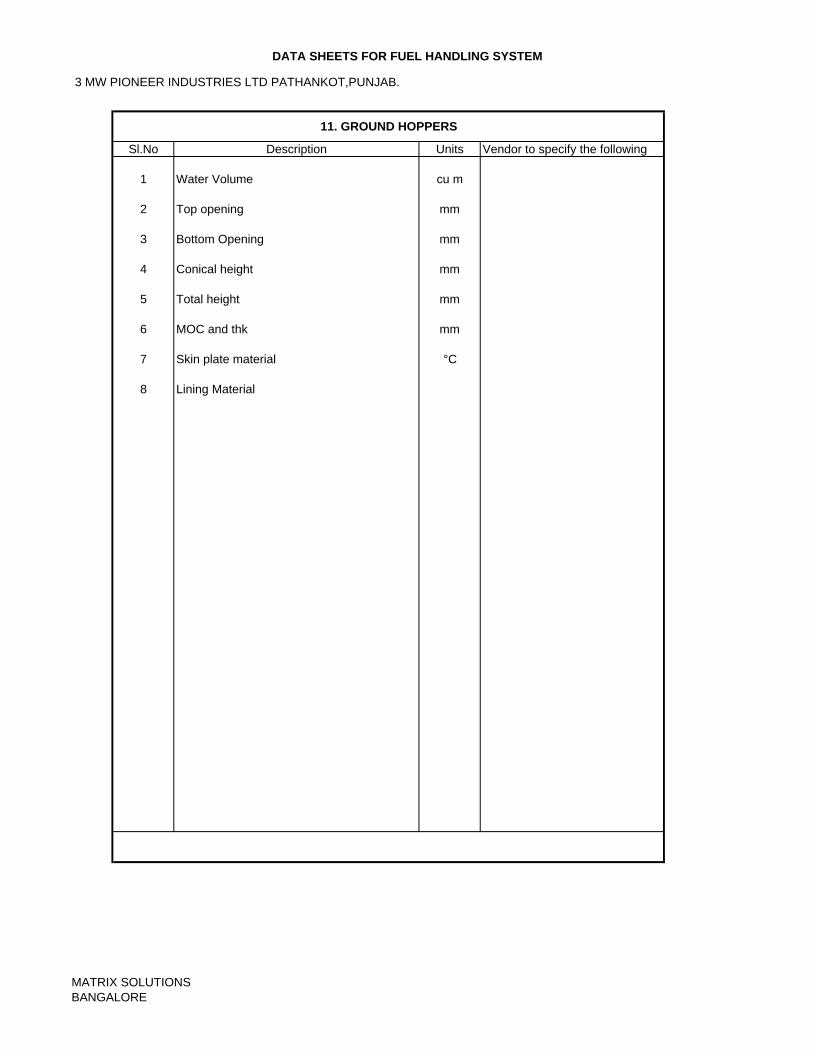
3 MW PIONEER INDUSTRIES LTD PATHANKOT,PUNJAB.
DATA SHEETS FOR FUEL HANDLING SYSTEM
Sl.No Units Vendor to specify the following
1 Water Volume cu m
2 Top opening mm
3 Bottom Opening mm
4 Conical height mm
5 Total height mm
6 MOC and thk mm
7 Skin plate material °C
8 Lining Material
11. GROUND HOPPERS
Description
MATRIX SOLUTIONSBANGALORE
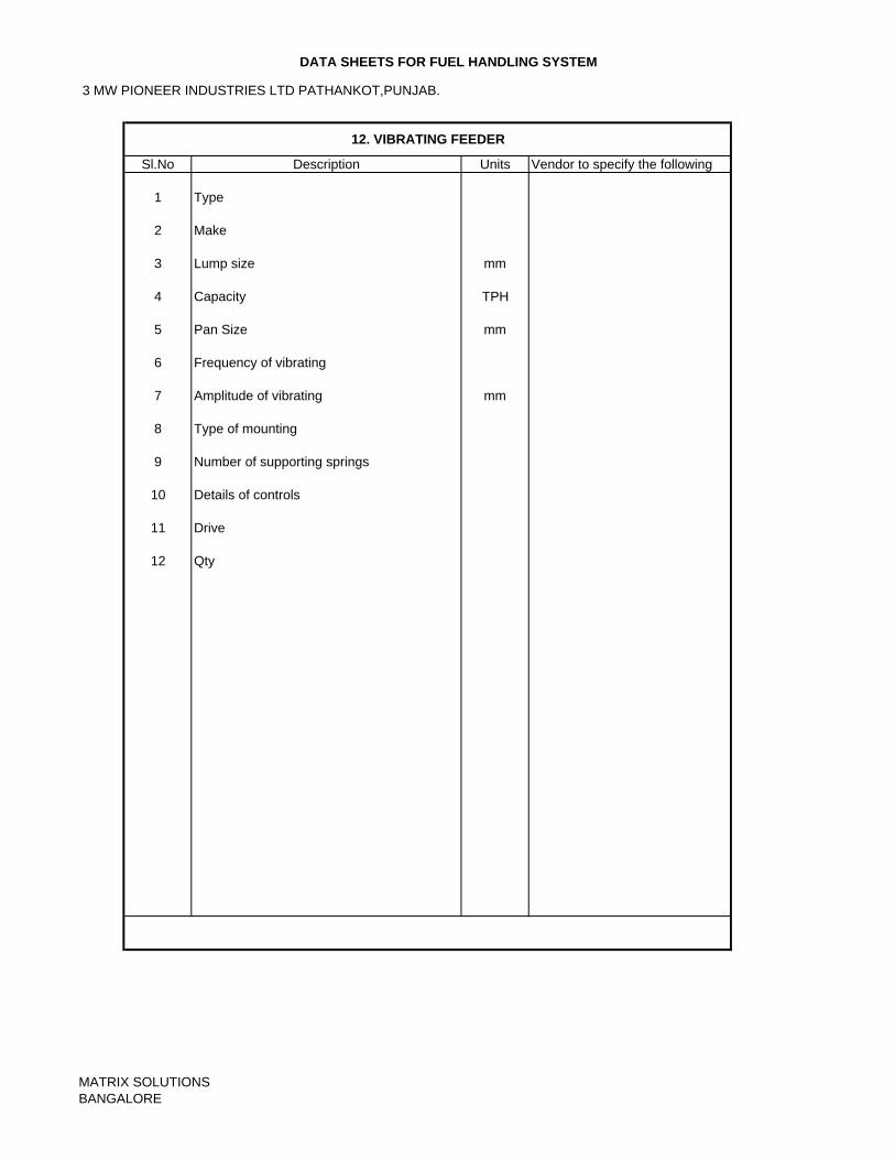
3 MW PIONEER INDUSTRIES LTD PATHANKOT,PUNJAB.
DATA SHEETS FOR FUEL HANDLING SYSTEM
Sl.No Units Vendor to specify the following
1 Type
2 Make
3 Lump size mm
4 Capacity TPH
5 Pan Size mm
6 Frequency of vibrating
7 Amplitude of vibrating mm
8 Type of mounting
9 Number of supporting springs
10 Details of controls
11 Drive
12 Qty
12. VIBRATING FEEDER
Description
MATRIX SOLUTIONSBANGALORE
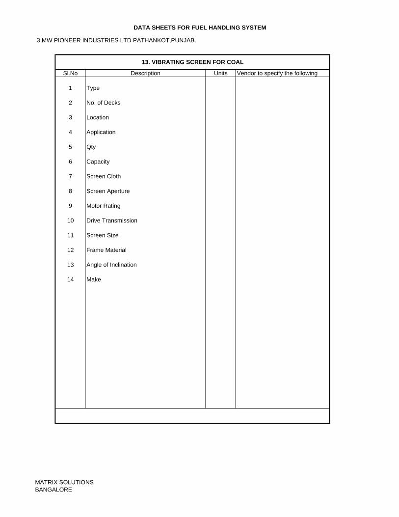
3 MW PIONEER INDUSTRIES LTD PATHANKOT,PUNJAB.
DATA SHEETS FOR FUEL HANDLING SYSTEM
Sl.No Units Vendor to specify the following
1 Type
2 No. of Decks
3 Location
4 Application
5 Qty
6 Capacity
7 Screen Cloth
8 Screen Aperture
9 Motor Rating
10 Drive Transmission
11 Screen Size
12 Frame Material
13 Angle of Inclination
14 Make
13. VIBRATING SCREEN FOR COAL
Description
MATRIX SOLUTIONSBANGALORE
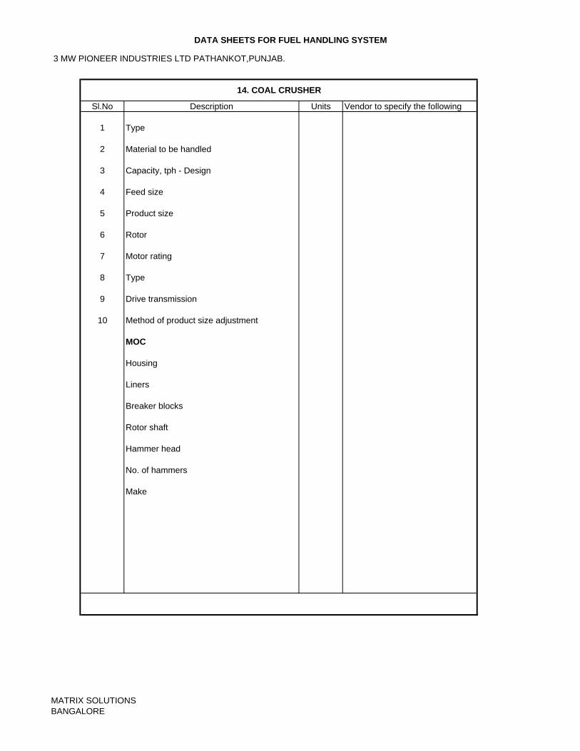
3 MW PIONEER INDUSTRIES LTD PATHANKOT,PUNJAB.
DATA SHEETS FOR FUEL HANDLING SYSTEM
Sl.No Units Vendor to specify the following
1 Type
2 Material to be handled
3 Capacity, tph - Design
4 Feed size
5 Product size
6 Rotor
7 Motor rating
8 Type
9 Drive transmission
10 Method of product size adjustment
MOC
Housing
Liners
Breaker blocks
Rotor shaft
Hammer head
No. of hammers
Make
14. COAL CRUSHER
Description
MATRIX SOLUTIONSBANGALORE
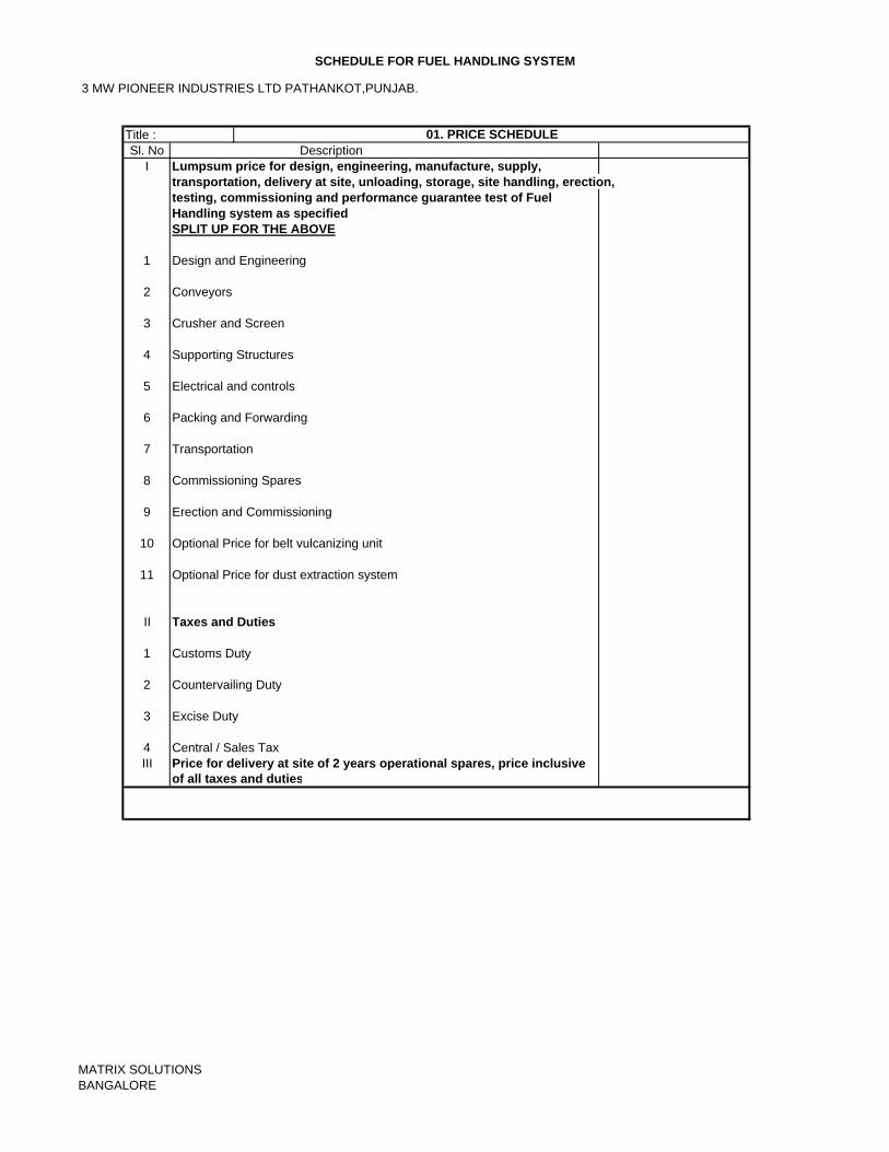
3 MW PIONEER INDUSTRIES LTD PATHANKOT,PUNJAB.
SCHEDULE FOR FUEL HANDLING SYSTEM
Sl. No DescriptionI Lumpsum price for design, engineering, manufacture, supply, transportation, delivery at site, unloading, storage, site handling, erection,
testing, commissioning and performance guarantee test of FuelHandling system as specifiedSPLIT UP FOR THE ABOVE
1 Design and Engineering
2 Conveyors
3 Crusher and Screen
4 Supporting Structures
5 Electrical and controls
6 Packing and Forwarding
7 Transportation
8 Commissioning Spares
9 Erection and Commissioning
10 Optional Price for belt vulcanizing unit
11 Optional Price for dust extraction system
II Taxes and Duties
1 Customs Duty
2 Countervailing Duty
3 Excise Duty
4 Central / Sales TaxIII Price for delivery at site of 2 years operational spares, price inclusive
of all taxes and duties
Title : 01. PRICE SCHEDULE
MATRIX SOLUTIONSBANGALORE
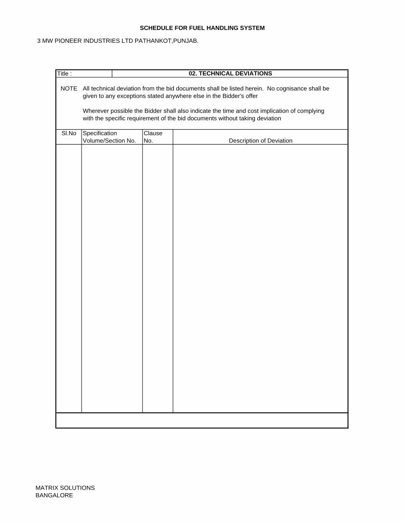
3 MW PIONEER INDUSTRIES LTD PATHANKOT,PUNJAB.
SCHEDULE FOR FUEL HANDLING SYSTEM
NOTE All technical deviation from the bid documents shall be listed herein. No cognisance shall be given to any exceptions stated anywhere else in the Bidder's offer
Wherever possible the Bidder shall also indicate the time and cost implication of complying with the specific requirement of the bid documents without taking deviation
Sl.No
Title : 02. TECHNICAL DEVIATIONS
Specification Volume/Section No.
Clause No. Description of Deviation
MATRIX SOLUTIONSBANGALORE
3 MW PIONEER INDUSTRIES LTD PATHANKOT,PUNJAB.
SCHEDULE FOR FUEL HANDLING SYSTEM
NOTE All commercial deviation from the bid documents shall be listed herein. No cognisance shall be given to any exceptions stated anywhere else in the Bidder's offer
Wherever possible the Bidder shall also indicate the time and cost implication of complying with the specific requirement of the bid documents without taking deviation
Sl.No
Title : 03. COMMERCIAL DEVIATIONS
Specification Volume/Section No.
Clause No. Description of Deviation
MATRIX SOLUTIONSBANGALORE
3 MW PIONEER INDUSTRIES LTD PATHANKOT,PUNJAB.
SCHEDULE FOR FUEL HANDLING SYSTEM
NOTE: The weights and overall dimensions of major packages shall be listed here.
Sl.No
Title : 04. WEIGHTS AND DIMENSIONS
Description of the items contained in the package
Overall Dimensions
of the Package in
Metres
Gross Weight
(in DU. No
MATRIX SOLUTIONSBANGALORE
3 MW PIONEER INDUSTRIES LTD PATHANKOT,PUNJAB.
SCHEDULE FOR FUEL HANDLING SYSTEM
NOTE: The special tools for the routine & emergency maintenance of the plant shall be listed here.
Sl.No Component Description Remarks
Title : 05. SPECIAL TOOLS & TACKLES FOR MAINTENANCE
Application
MATRIX SOLUTIONSBANGALORE
3 MW PIONEER INDUSTRIES LTD PATHANKOT,PUNJAB.
SCHEDULE FOR FUEL HANDLING SYSTEM
NOTE: The spares recommended should be adequate for 2 years of opeation.
Sl.No Name of the Spare Part Catalogue / Drawing Required Qty. of No. identifying the Qty. of the item Price Spare Parts Spares in use
Title : 06. RECOMMENDED OPERATIONAL SPARES
MATRIX SOLUTIONSBANGALORE
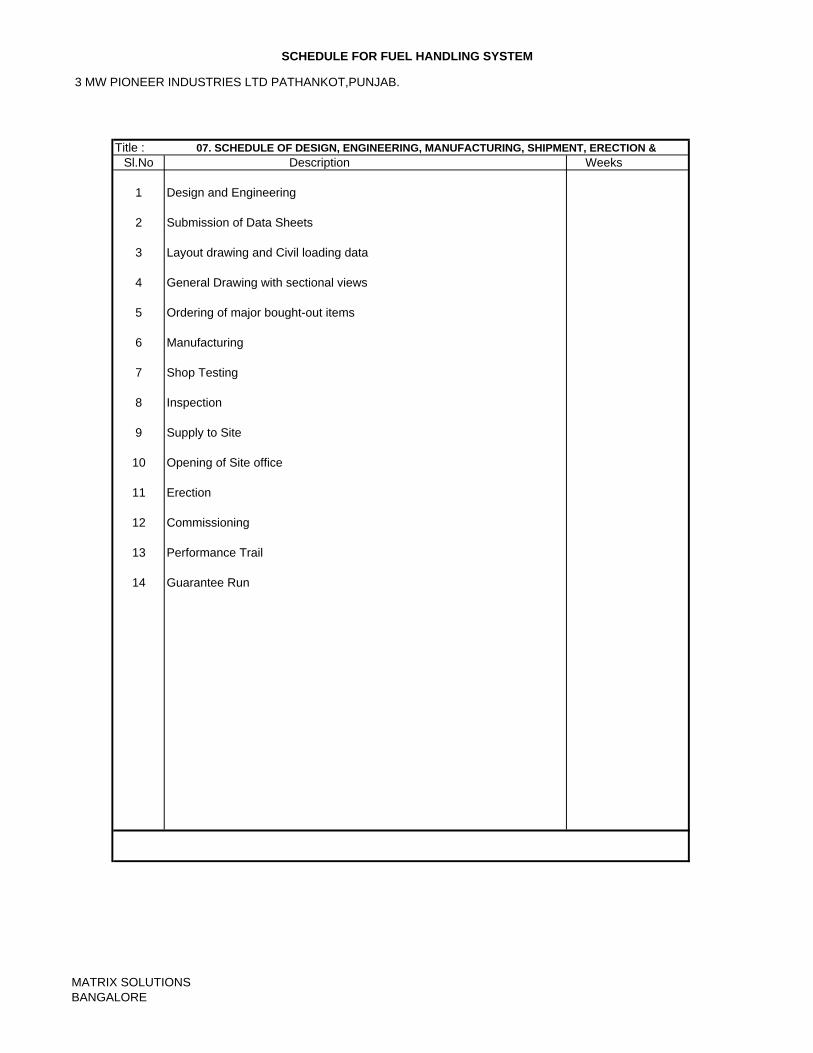
3 MW PIONEER INDUSTRIES LTD PATHANKOT,PUNJAB.
SCHEDULE FOR FUEL HANDLING SYSTEM
Title :Sl.No Description Weeks
1 Design and Engineering
2 Submission of Data Sheets
3 Layout drawing and Civil loading data
4 General Drawing with sectional views
5 Ordering of major bought-out items
6 Manufacturing
7 Shop Testing
8 Inspection
9 Supply to Site
10 Opening of Site office
11 Erection
12 Commissioning
13 Performance Trail
14 Guarantee Run
07. SCHEDULE OF DESIGN, ENGINEERING, MANUFACTURING, SHIPMENT, ERECTION &
MATRIX SOLUTIONSBANGALORE
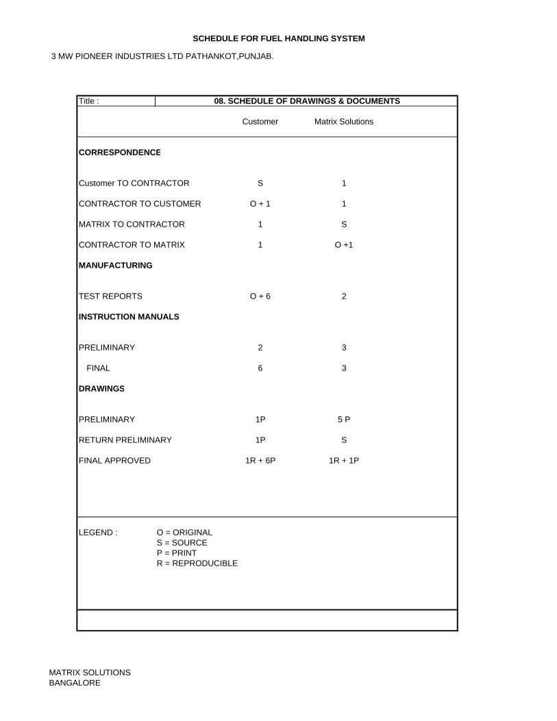
3 MW PIONEER INDUSTRIES LTD PATHANKOT,PUNJAB.
SCHEDULE FOR FUEL HANDLING SYSTEM
Customer Matrix Solutions
CORRESPONDENCE
Customer TO CONTRACTOR S 1
CONTRACTOR TO CUSTOMER O + 1 1
MATRIX TO CONTRACTOR 1 S
CONTRACTOR TO MATRIX 1 O +1
MANUFACTURING
TEST REPORTS O + 6 2
INSTRUCTION MANUALS
PRELIMINARY 2 3
FINAL 6 3
DRAWINGS
PRELIMINARY 1P 5 P
RETURN PRELIMINARY 1P S
FINAL APPROVED 1R + 6P 1R + 1P
LEGEND : O = ORIGINALS = SOURCEP = PRINTR = REPRODUCIBLE
Title : 08. SCHEDULE OF DRAWINGS & DOCUMENTS
MATRIX SOLUTIONSBANGALORE
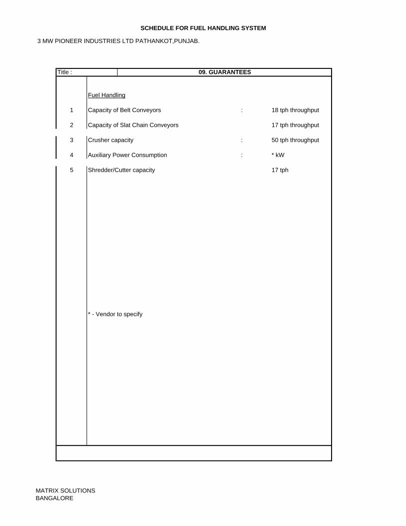
3 MW PIONEER INDUSTRIES LTD PATHANKOT,PUNJAB.
SCHEDULE FOR FUEL HANDLING SYSTEM
Fuel Handling
1 Capacity of Belt Conveyors : 18 tph throughput
2 Capacity of Slat Chain Conveyors 17 tph throughput
3 Crusher capacity : 50 tph throughput
4 Auxiliary Power Consumption : * kW
5 Shredder/Cutter capacity 17 tph
* - Vendor to specify
Title : 09. GUARANTEES
MATRIX SOLUTIONSBANGALORE