Embed Size (px)
Citation preview

Fuel Cells:Types
Prof. Antonella Glisenti - Dip. Scienze Chimiche - Università degli Studi di Padova
Laurea Magistrale in Scienza dei MaterialiMateriali Inorganici Funzionali
Prof. Antonella Glisenti - Dip. Scienze Chimiche - Università degli Studi di Padova
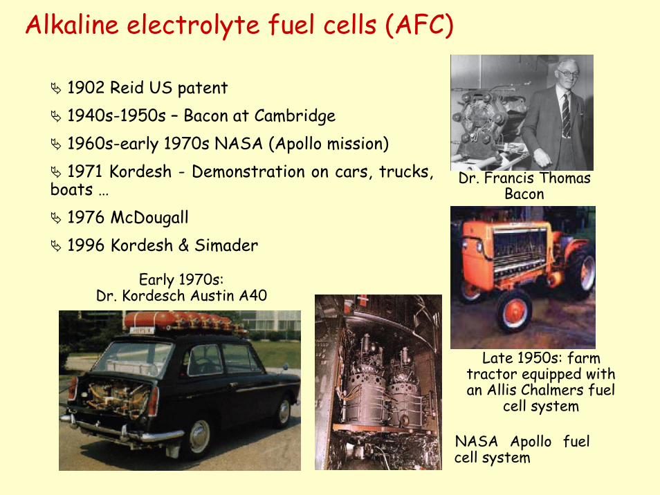
Alkaline electrolyte fuel cells (AFC)
1902 Reid US patent1940s-1950s – Bacon at Cambridge1960s-early 1970s NASA (Apollo mission)1971 Kordesh - Demonstration on cars, trucks,
boats …1976 McDougall1996 Kordesh & Simader
Dr. Francis Thomas Bacon
Late 1950s: farm tractor equipped with an Allis Chalmers fuel
cell system
NASA Apollo fuel cell system
Early 1970s: Dr. Kordesch Austin A40
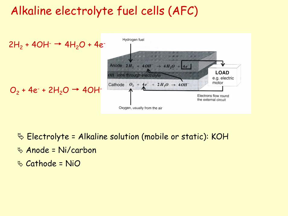
Electrolyte = Alkaline solution (mobile or static): KOH Anode = Ni/carbonCathode = NiO
Alkaline electrolyte fuel cells (AFC)
2H2 + 4OH- 4H2O + 4e-
O2 + 4e- + 2H2O 4OH-
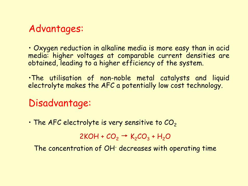
Advantages:
• Oxygen reduction in alkaline media is more easy than in acid media: higher voltages at comparable current densities are obtained, leading to a higher efficiency of the system.
•The utilisation of non-noble metal catalysts and liquid electrolyte makes the AFC a potentially low cost technology.
Disadvantage:
• The AFC electrolyte is very sensitive to CO2
2KOH + CO2 K2CO3 + H2OThe concentration of OH- decreases with operating time
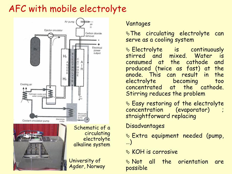
VantagesThe circulating electrolyte can
serve as a cooling system Electrolyte is continuously
stirred and mixed. Water is consumed at the cathode and produced (twice as fast) at the anode. This can result in the electrolyte becoming too concentrated at the cathode. Stirring reduces the problem
Easy restoring of the electrolyte concentration (evaporator) ; straightforward replacing Disadvantages
Extra equipment needed (pump, …)
KOH is corrosiveNot all the orientation are
possible
AFC with mobile electrolyte
University of Agder, Norway
Schematic of a circulating electrolyte
alkaline system
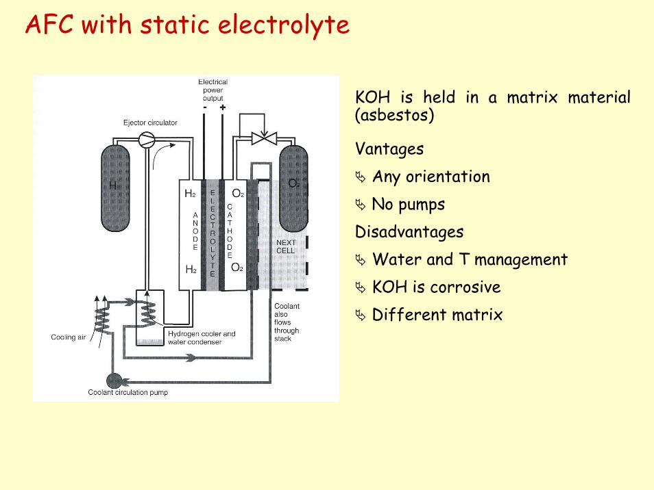
KOH is held in a matrix material (asbestos)
AFC with static electrolyte
VantagesAny orientation No pumps
DisadvantagesWater and T managementKOH is corrosiveDifferent matrix
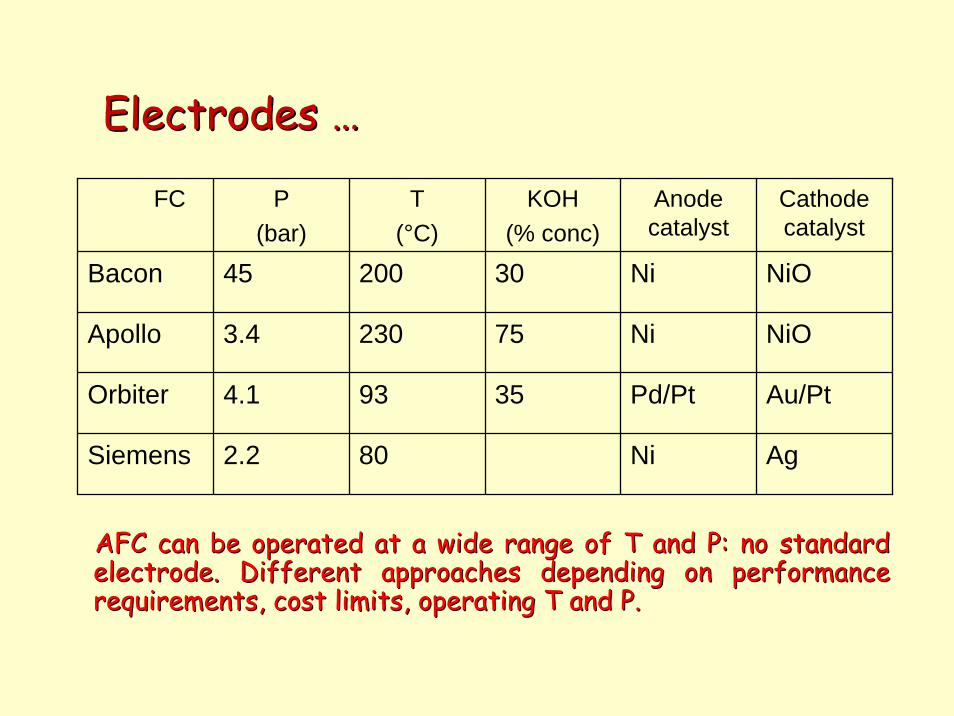
Electrodes …
High permeability to gases
High structural strength
Good corrosion resistance
High electronic conductivity
Electro-catalytic attitude
Low price
AFC can be operated at a wide range of T and P: no standard AFC can be operated at a wide range of T and P: no standard electrode. Different approaches depending on performance electrode. Different approaches depending on performance requirements, cost limits, operating T and P. requirements, cost limits, operating T and P.
Electrodes Electrodes ……
AFC can be operated at a wide range of T and P: no standard AFC can be operated at a wide range of T and P: no standard electrode. Different approaches depending on performance electrode. Different approaches depending on performance requirements, cost limits, operating T and P. requirements, cost limits, operating T and P.
FC P(bar)
T(°C)
KOH(% conc)
Anodecatalyst
Cathodecatalyst
Bacon 45 200 30 Ni NiO
Apollo 3.4 230 75 Ni NiO
Orbiter 4.1 93 35 Pd/Pt Au/Pt
Siemens 2.2 80 Ni Ag
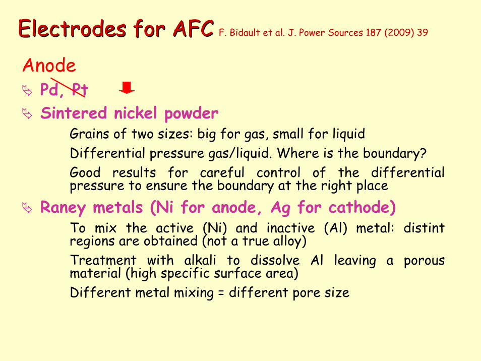
AnodePd, PtSintered nickel powder
Grains of two sizes: big for gas, small for liquidDifferential pressure gas/liquid. Where is the boundary?Good results for careful control of the differential pressure to ensure the boundary at the right place
Raney metals (Ni for anode, Ag for cathode)To mix the active (Ni) and inactive (Al) metal: distintregions are obtained (not a true alloy)Treatment with alkali to dissolve Al leaving a porous material (high specific surface area)Different metal mixing = different pore size
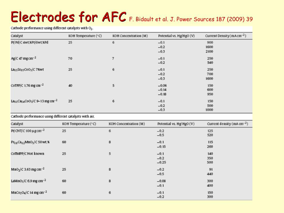
Electrodes for AFCElectrodes for AFC F. Bidault et al. J. Power Sources 187 (2009) 39
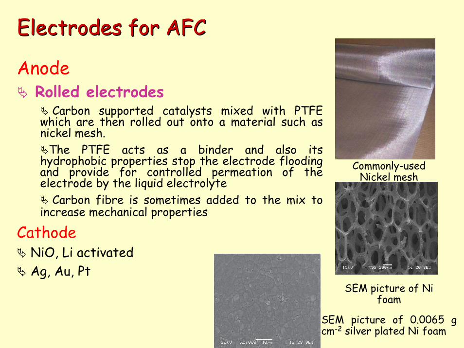
AnodeRolled electrodes
Carbon supported catalysts mixed with PTFE which are then rolled out onto a material such as nickel mesh.
The PTFE acts as a binder and also its hydrophobic properties stop the electrode flooding and provide for controlled permeation of the electrode by the liquid electrolyte
Carbon fibre is sometimes added to the mix to increase mechanical properties
CathodeNiO, Li activatedAg, Au, Pt
Electrodes for AFCElectrodes for AFC
SEM picture of Ni foam
Commonly-used Nickel mesh
SEM picture of 0.0065 g cm-2 silver plated Ni foam
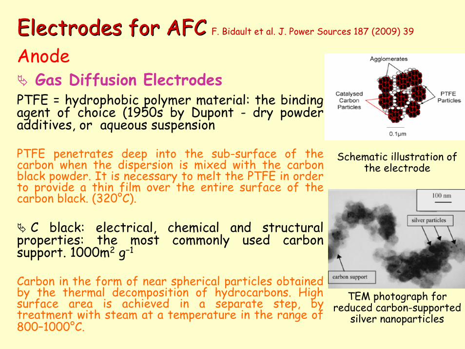
AnodeGas Diffusion Electrodes
PTFE = hydrophobic polymer material: the binding agent of choice (1950s by Dupont - dry powder additives, or aqueous suspension
PTFE penetrates deep into the sub-surface of the carbon when the dispersion is mixed with the carbon black powder. It is necessary to melt the PTFE in order to provide a thin film over the entire surface of the carbon black. (320°C).
C black: electrical, chemical and structural properties: the most commonly used carbon support. 1000m2 g−1
Carbon in the form of near spherical particles obtained by the thermal decomposition of hydrocarbons. High surface area is achieved in a separate step, by treatment with steam at a temperature in the range of 800–1000°C.
Schematic illustration of the electrode
Electrodes for AFCElectrodes for AFC F. Bidault et al. J. Power Sources 187 (2009) 39
TEM photograph for reduced carbon-supported
silver nanoparticles
Electrodes for AFCElectrodes for AFC F. Bidault et al. J. Power Sources 187 (2009) 39
Phosphoric acid fuel cells (PAFC)
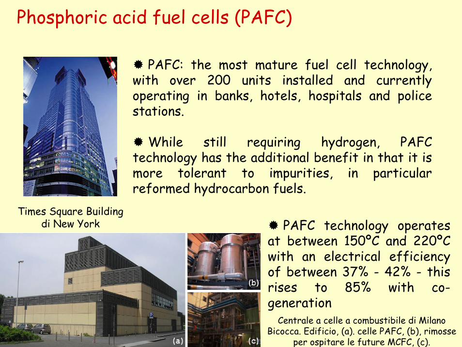
Times Square Building di New York
PAFC: the most mature fuel cell technology, with over 200 units installed and currentlyoperating in banks, hotels, hospitals and policestations.
While still requiring hydrogen, PAFC technology has the additional benefit in that it ismore tolerant to impurities, in particularreformed hydrocarbon fuels.
PAFC technology operatesat between 150ºC and 220ºC with an electrical efficiencyof between 37% - 42% - thisrises to 85% with co-generation
Centrale a celle a combustibile di Milano Bicocca. Edificio, (a). celle PAFC, (b), rimosse
per ospitare le future MCFC, (c).
Phosphoric acid fuel cells (PAFC)
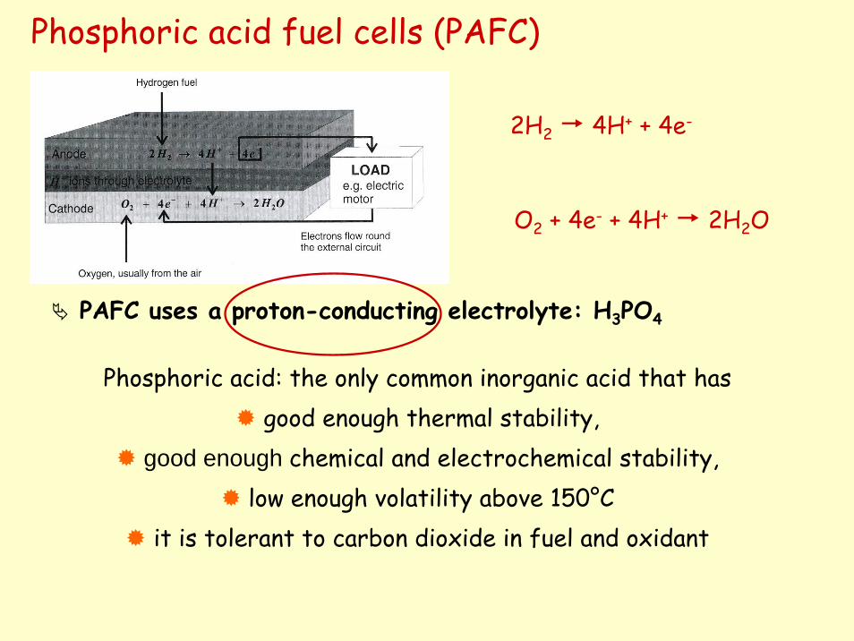
PAFC uses a proton-conducting electrolyte: H3PO4
Phosphoric acid: the only common inorganic acid that hasgood enough thermal stability,
good enough chemical and electrochemical stability, low enough volatility above 150°C
it is tolerant to carbon dioxide in fuel and oxidant
2H2 4H+ + 4e-
O2 + 4e- + 4H+ 2H2O
Phosphoric acid fuel cells (PAFC)
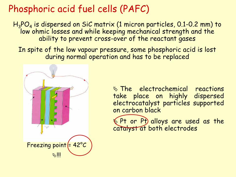
The electrochemical reactions take place on highly dispersed electrocatalyst particles supported on carbon black
Pt or Pt alloys are used as the catalyst at both electrodes
H3PO4 is dispersed on SiC matrix (1 micron particles, 0.1-0.2 mm) to low ohmic losses and while keeping mechanical strength and the
ability to prevent cross-over of the reactant gasesIn spite of the low vapour pressure, some phosphoric acid is lost
during normal operation and has to be replaced
Freezing point = 42°C!!!
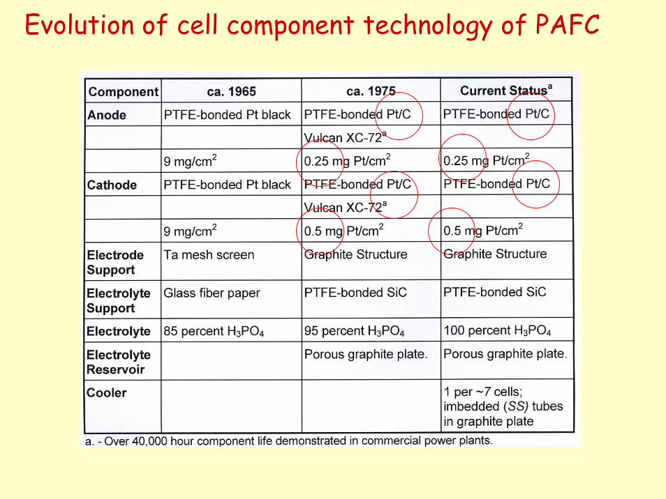
Evolution of cell component technology of PAFC
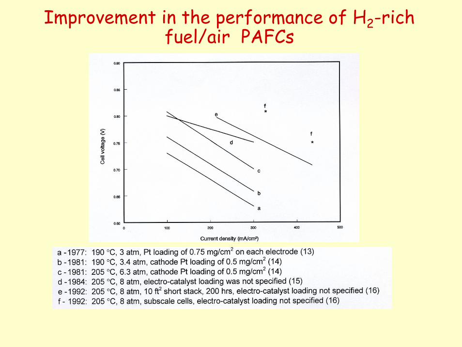
Improvement in the performance of H2-rich fuel/air PAFCs
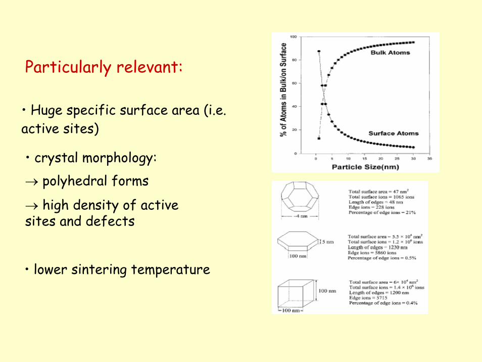
Particularly relevant:
• Huge specific surface area (i.e. active sites)
• crystal morphology:→ polyhedral forms
→ high density of activesites and defects
• lower sintering temperature
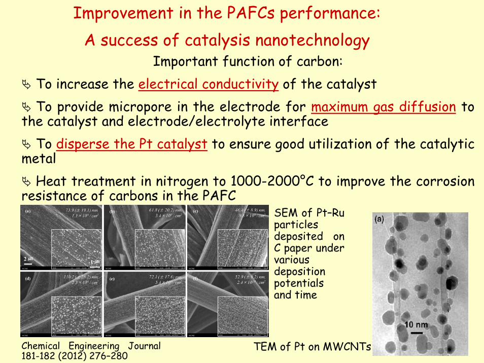
Improvement in the PAFCs performance:A success of catalysis nanotechnology
Important function of carbon:To increase the electrical conductivity of the catalystTo provide micropore in the electrode for maximum gas diffusion to
the catalyst and electrode/electrolyte interfaceTo disperse the Pt catalyst to ensure good utilization of the catalytic
metalHeat treatment in nitrogen to 1000-2000°C to improve the corrosion
resistance of carbons in the PAFC
TEM of Pt on MWCNTs
SEM of Pt–Ruparticlesdeposited on C paper under variousdepositionpotentialsand time
Chemical Engineering Journal 181-182 (2012) 276–280
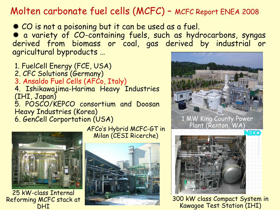
Molten carbonate fuel cells (MCFC) – MCFC Report ENEA 2008
CO is not a poisoning but it can be used as a fuel. a variety of CO-containing fuels, such as hydrocarbons, syngas
derived from biomass or coal, gas derived by industrial or agricultural byproducts …
1. FuelCell Energy (FCE, USA)2. CFC Solutions (Germany)3. Ansaldo Fuel Cells (AFCo, Italy)4. Ishikawajima-Harima Heavy Industries (IHI, Japan)5. POSCO/KEPCO consortium and DoosanHeavy Industries (Korea)6. GenCell Corportation (USA) 1 MW King County Power
Plant (Renton, WA)
300 kW class Compact System in Kawagoe Test Station (IHI)
25 kW-class Internal Reforming MCFC stack at
DHI
AFCo’s Hybrid MCFC-GT in Milan (CESI Ricerche)
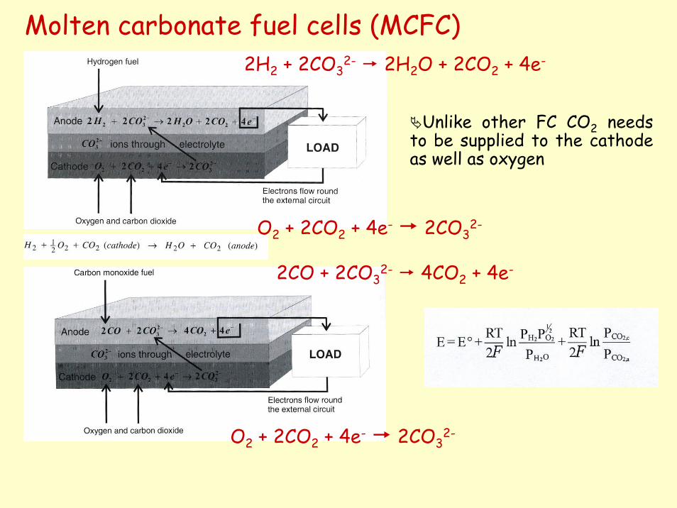
Molten carbonate fuel cells (MCFC)
Unlike other FC CO2 needs to be supplied to the cathode as well as oxygen
2H2 + 2CO32- 2H2O + 2CO2 + 4e-
O2 + 2CO2 + 4e- 2CO32-
2CO + 2CO32- 4CO2 + 4e-
O2 + 2CO2 + 4e- 2CO32-
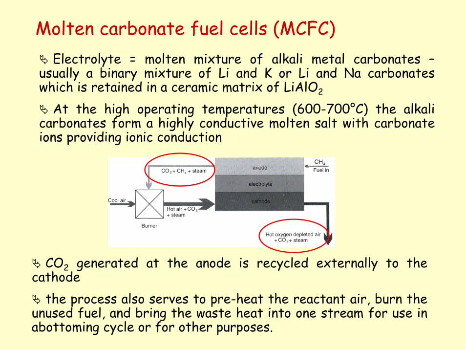
Molten carbonate fuel cells (MCFC)Electrolyte = molten mixture of alkali metal carbonates –
usually a binary mixture of Li and K or Li and Na carbonates which is retained in a ceramic matrix of LiAlO2
At the high operating temperatures (600-700°C) the alkali carbonates form a highly conductive molten salt with carbonate ions providing ionic conduction
CO2 generated at the anode is recycled externally to the cathode
the process also serves to pre-heat the reactant air, burn the unused fuel, and bring the waste heat into one stream for use inabottoming cycle or for other purposes.
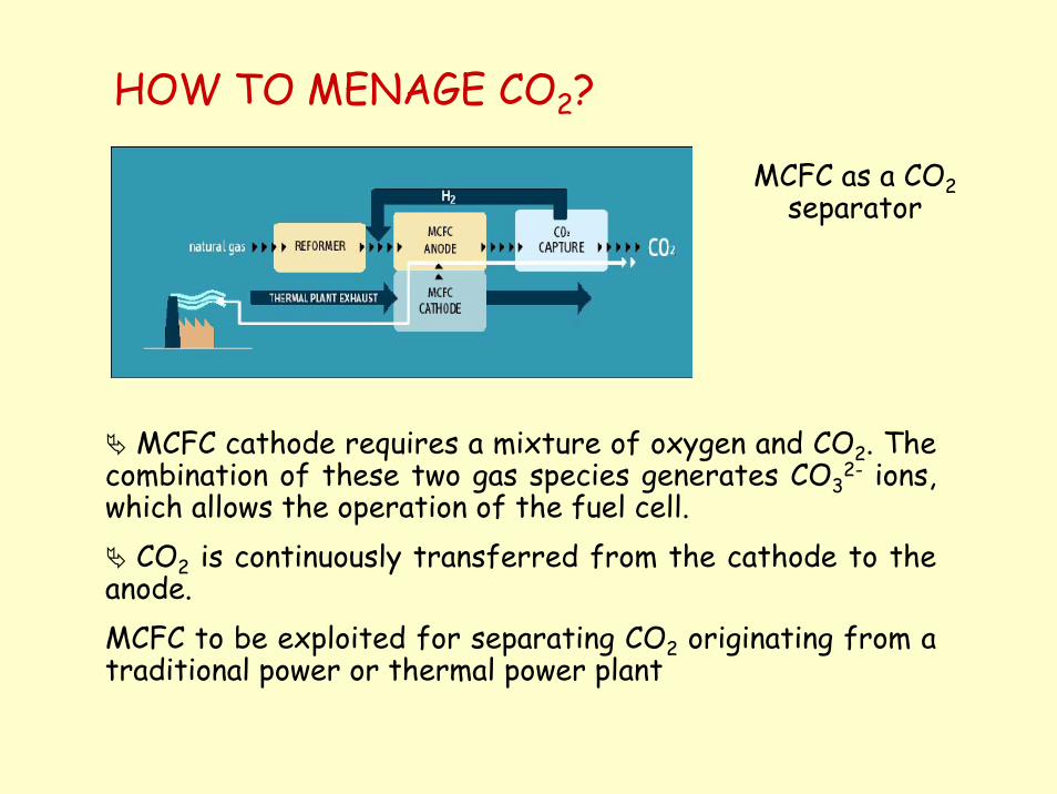
HOW TO MENAGE CO2?
MCFC as a CO2separator
MCFC cathode requires a mixture of oxygen and CO2. The combination of these two gas species generates CO3
2- ions, which allows the operation of the fuel cell.
CO2 is continuously transferred from the cathode to the anode. MCFC to be exploited for separating CO2 originating from a traditional power or thermal power plant
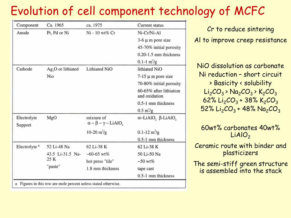
Evolution of cell component technology of MCFC
60wt% carbonates 40wt% LiAlO2
Ceramic route with binder and plasticizers
The semi-stiff green structure is assembled into the stack
Cr to reduce sinteringAl to improve creep resistance
NiO dissolution as carbonateNi reduction – short circuit
> Basicity < solubilityLi2CO3 > Na2CO3 > K2CO362% Li2CO3 + 38% K2CO3
52% Li2CO3 + 48% Na2CO3
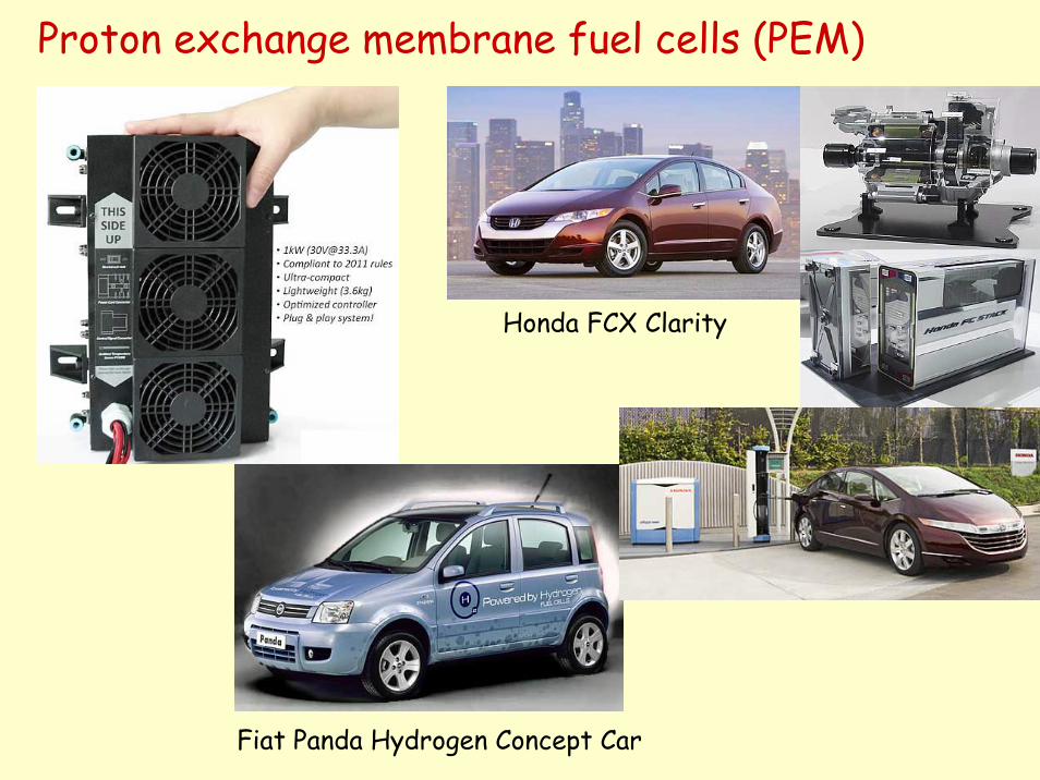
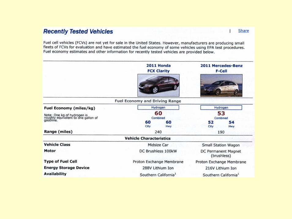
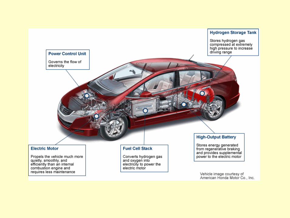
Proton exchange membrane fuel cells (PEM)
Honda FCX Clarity
Fiat Panda Hydrogen Concept Car
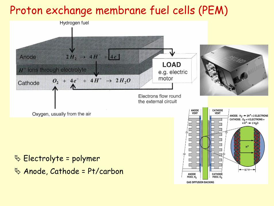
Electrolyte = polymer Anode, Cathode = Pt/carbon
Proton exchange membrane fuel cells (PEM)
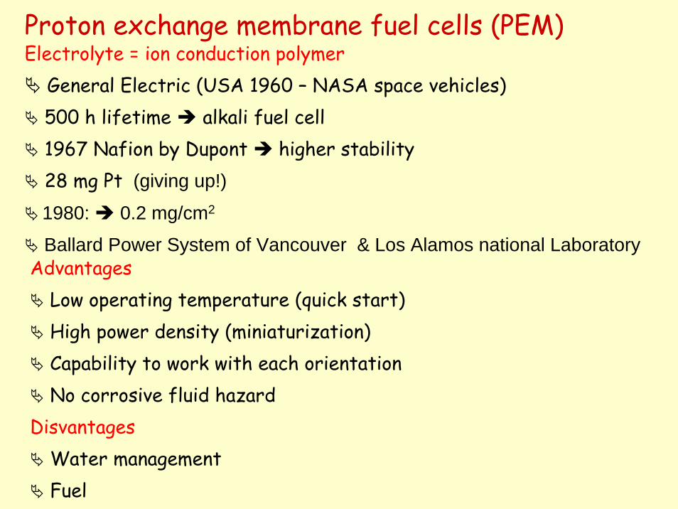
Proton exchange membrane fuel cells (PEM)Electrolyte = ion conduction polymer
General Electric (USA 1960 – NASA space vehicles) 500 h lifetime alkali fuel cell1967 Nafion by Dupont higher stability28 mg Pt (giving up!)
1980: 0.2 mg/cm2
Ballard Power System of Vancouver & Los Alamos national LaboratoryAdvantages
Low operating temperature (quick start)High power density (miniaturization)Capability to work with each orientationNo corrosive fluid hazard
DisvantagesWater managementFuel
How the polymer electrolyte works
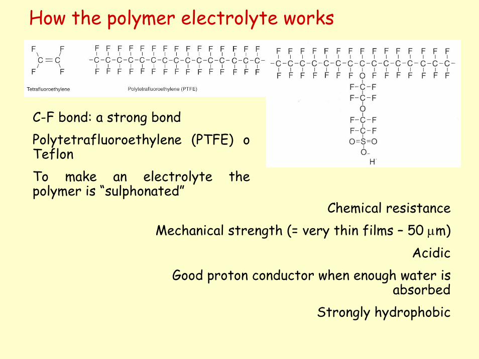
Chemical resistanceMechanical strength (= very thin films – 50 μm)
AcidicGood proton conductor when enough water is
absorbedStrongly hydrophobic
C-F bond: a strong bondPolytetrafluoroethylene (PTFE) o TeflonTo make an electrolyte the polymer is “sulphonated”
How the polymer electrolyte works
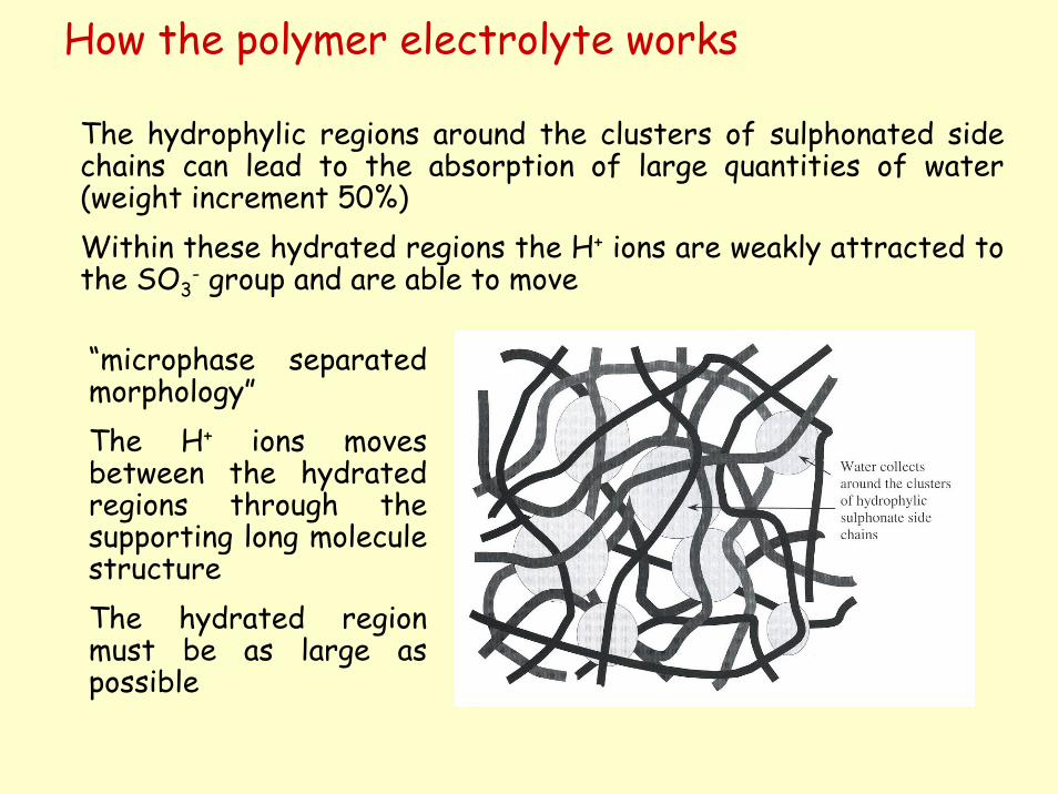
The hydrophylic regions around the clusters of sulphonated side chains can lead to the absorption of large quantities of water (weight increment 50%)Within these hydrated regions the H+ ions are weakly attracted to the SO3
- group and are able to move
“microphase separated morphology”The H+ ions moves between the hydrated regions through the supporting long molecule structureThe hydrated region must be as large as possible
Electrodes and electrode structure
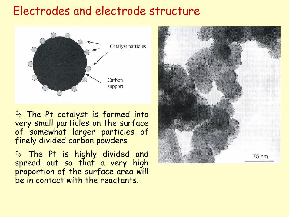
The Pt catalyst is formed into very small particles on the surface of somewhat larger particles of finely divided carbon powders
The Pt is highly divided and spread out so that a very high proportion of the surface area will be in contact with the reactants.
Electrodes and electrode structure
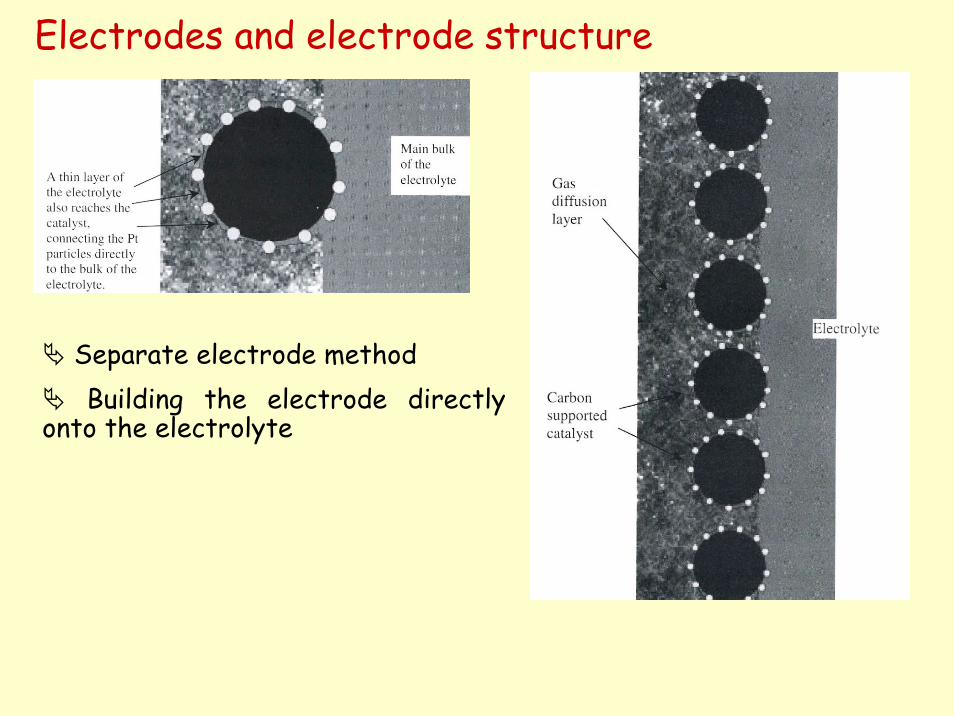
Separate electrode methodBuilding the electrode directly
onto the electrolyte
Electrodes and electrode structure
Separate electrode methodThe carbon supported catalyst is fixed to a porous and conductive
material (carbon cloth or carbon paper)PTFE is often added because it is hydrophobic (and help
expelling water)C cloth or paper = gas diffusion layer
An electrode is then fixed to each side of a piece of polymer electrolyte membrane
PROCEDURE:1. membrane is cleaned (boiling in 3% H2O2 water 1h)2. membrane is treated with boiling H2SO4 (for protonation)3. membrane is rinsed in boiling de-ionised water for 1h (to remove acid in excess)4. electrodes are put onto the electrolyte membrane and the assembly hot pressed at 140°C (3 min)
Electrodes and electrode structure
Building the electrode directly onto the electrolyteThe Pt on carbon catalyst is fixed directly to the electrolyte thus
manufacturing the electrode directly onto the membraneThe catalyst (often mixed with hydrophobic PTFE) is applied to
the electrolyte membrane using rolling methods, or spraying, or adapted printing process
The gases diffusion layer (C cloth or paper) is appliedGas diffusion layer:
1. It forms an electrical connection2. It carries the product water away from the electrolyte 3. It forms a protective layer over the very thin layer of catalyst
Improvement in the FCs performance:A success of catalysis nanotechnology
The PTFE binds the carbon black particles together to form an integral (but porous) structure, which is supported on a porous carbon paper substrate.
The carbon paper serves as a structural support for the electrocatalyst layer as well as acting as the current collector.
A typical carbon paper has an initial porosity of about 90% which is reduced at 60% by impregnation with 40% wt. of PTFE.
The carbon paper contains macropores of 3 to 50 micron diameter (median 12.5 microns) and micropores with median diameter of about 3.4 nm for gas permeability.
The composite structure consisting of a carbon black/PTFE layer on carbon paper substrate forms a stable, three phase interface in the fuel cell (electrolyte on one side, reactant gas on the other)
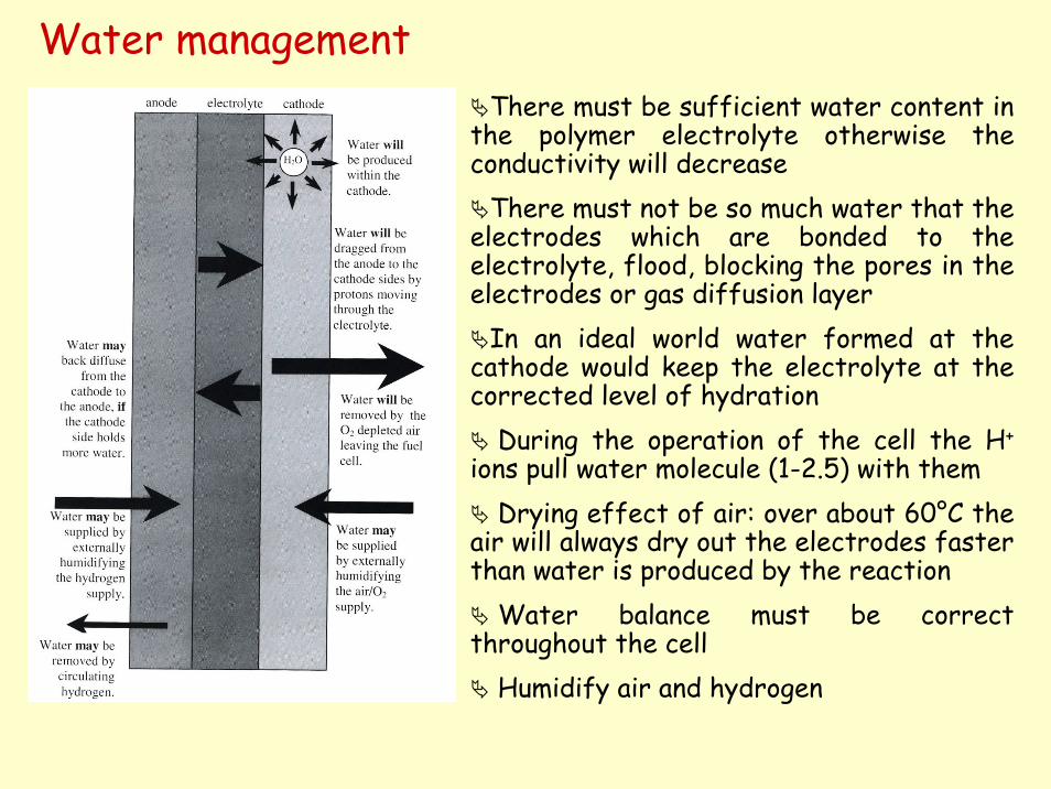
Water managementThere must be sufficient water content in
the polymer electrolyte otherwise the conductivity will decrease
There must not be so much water that the electrodes which are bonded to the electrolyte, flood, blocking the pores in the electrodes or gas diffusion layer
In an ideal world water formed at the cathode would keep the electrolyte at the corrected level of hydration
During the operation of the cell the H+
ions pull water molecule (1-2.5) with themDrying effect of air: over about 60°C the
air will always dry out the electrodes faster than water is produced by the reaction
Water balance must be correct throughout the cell
Humidify air and hydrogen
Research improvements (Wu et al. Science 332 (2011) 443-447)
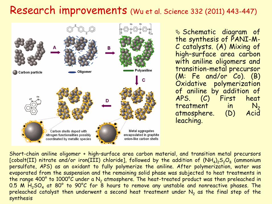
Schematic diagram of the synthesis of PANI-M-C catalysts. (A) Mixing of high–surface area carbon with aniline oligomers and transition-metal precursor (M: Fe and/or Co). (B) Oxidative polymerization of aniline by addition of APS. (C) First heat treatment in N2atmosphere. (D) Acid leaching.
Short-chain aniline oligomer + high–surface area carbon material, and transition metal precursors[cobalt(II) nitrate and/or iron(III) chloride], followed by the addition of (NH4)2S2O8 (ammoniumpersulfate, APS) as an oxidant to fully polymerize the aniline. After polymerization, water wasevaporated from the suspension and the remaining solid phase was subjected to heat treatments in the range 400° to 1000°C under a N2 atmosphere. The heat-treated product was then preleached in 0.5 M H2SO4 at 80° to 90°C for 8 hours to remove any unstable and nonreactive phases. The preleached catalyst then underwent a second heat treatment under N2 as the final step of the synthesis
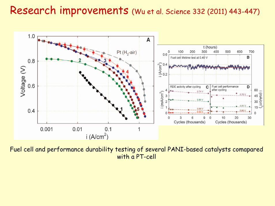
Research improvements (Wu et al. Science 332 (2011) 443-447)
Fuel cell and performance durability testing of several PANI-based catalysts comaparedwith a PT-cell
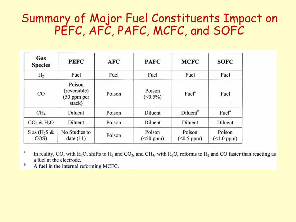
Summary of Major Fuel Constituents Impact on PEFC, AFC, PAFC, MCFC, and SOFC
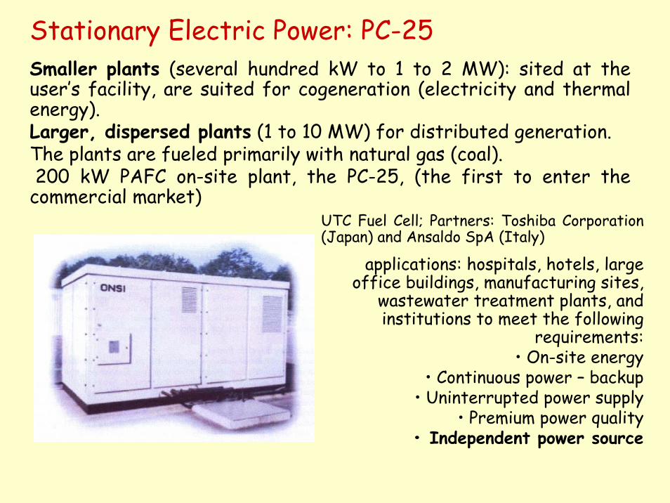
Stationary Electric Power: PC-25Smaller plants (several hundred kW to 1 to 2 MW): sited at the user’s facility, are suited for cogeneration (electricity and thermalenergy). Larger, dispersed plants (1 to 10 MW) for distributed generation. The plants are fueled primarily with natural gas (coal). 200 kW PAFC on-site plant, the PC-25, (the first to enter the
commercial market)UTC Fuel Cell; Partners: Toshiba Corporation (Japan) and Ansaldo SpA (Italy)
applications: hospitals, hotels, large office buildings, manufacturing sites,
wastewater treatment plants, and institutions to meet the following
requirements:• On-site energy
• Continuous power – backup• Uninterrupted power supply
• Premium power quality• Independent power source
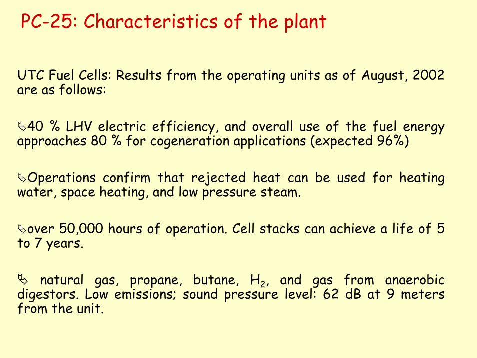
PC-25: Characteristics of the plant
UTC Fuel Cells: Results from the operating units as of August, 2002 are as follows:
40 % LHV electric efficiency, and overall use of the fuel energyapproaches 80 % for cogeneration applications (expected 96%)
Operations confirm that rejected heat can be used for heating water, space heating, and low pressure steam.
over 50,000 hours of operation. Cell stacks can achieve a life of 5 to 7 years.
natural gas, propane, butane, H2, and gas from anaerobic digestors. Low emissions; sound pressure level: 62 dB at 9 meters from the unit.
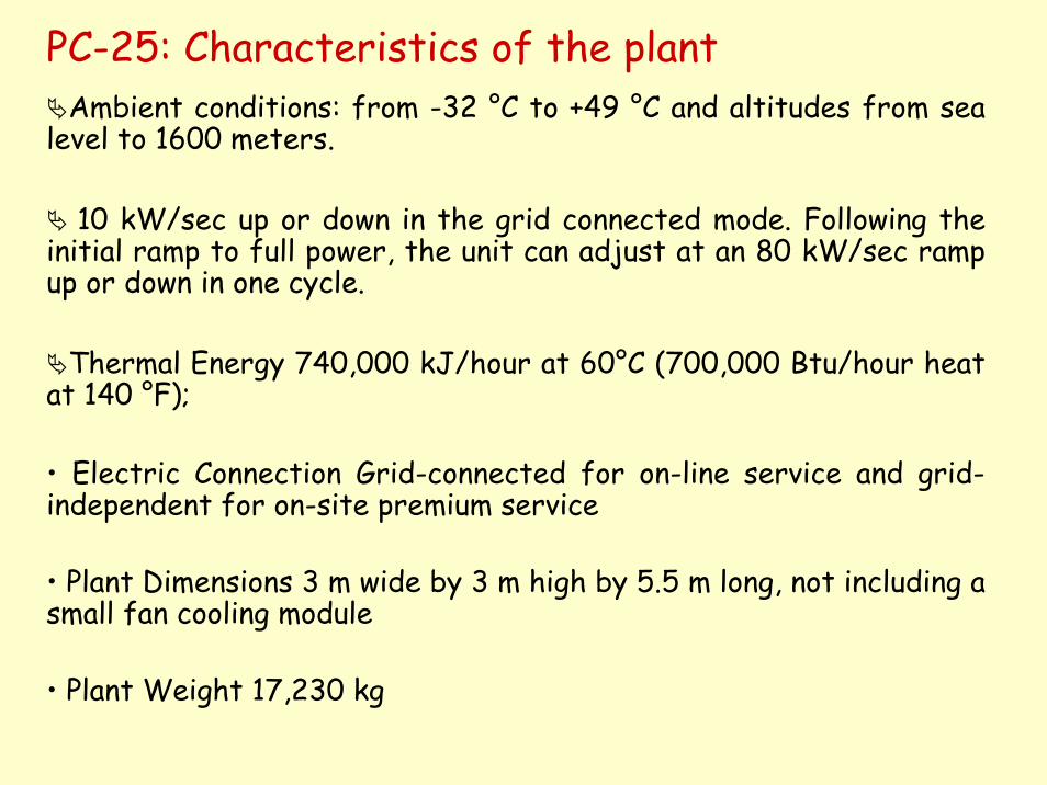
PC-25: Characteristics of the plantAmbient conditions: from -32 °C to +49 °C and altitudes from sea
level to 1600 meters.
10 kW/sec up or down in the grid connected mode. Following the initial ramp to full power, the unit can adjust at an 80 kW/sec ramp up or down in one cycle.
Thermal Energy 740,000 kJ/hour at 60°C (700,000 Btu/hour heat at 140 °F);
• Electric Connection Grid-connected for on-line service and grid-independent for on-site premium service
• Plant Dimensions 3 m wide by 3 m high by 5.5 m long, not including a small fan cooling module
• Plant Weight 17,230 kg
Vehicle Motive Power1970 K. Kordesch 1961 Austin A-40 (6-kW alkaline fuel cell – H2 - in conjunction with lead acid batteries)1994 and 1995, H-Power (Belleville, New Jersey) three 50 kW PAFC/battery hybrid transit buses. 1993 Ballard Power Systems (Burnaby, British Columbia, Canada) 10 m light-duty transit bus with a 120 kW fuel cell system, followed by a 200 kW, 12 meter heavy-duty transit bus in 1995. 1997 Ballard 205 kW (275 HP) PEFC units for full-size transit buses; Ballard-Daimler-Benz: PEFC-powered vehicles, ranging from passenger cars to buses. 1997 Methanol-fuelled PEFC A-class car by Daimler-Benz in 1997 1996 H2-fueled (metal hydride for hydrogen storage), fuel cell/battery hybrid passenger car by Toyota followed in 1997 by a methanol-fuelled car (RAV4) 2002 UTC Fuel Cells, Nissan, Renault
Other manufacturers: General Motors, Volkswagen, Volvo, Chrysler, Nissan, and Ford, have also announced plans to build PEM prototypeSoperating on hydrogen, methanol, or gasoline.
Several challenges, technical and otherwise, must be overcome before fuel cell vehicles (FCVs) will be a successful, competitive
alternative for consumers.
Onboard Hydrogen StorageVehicle Cost
Fuel Cell Durability and ReliabilityGetting Hydrogen to Consumers
Competition with Other TechnologiesSafety
Public Acceptance
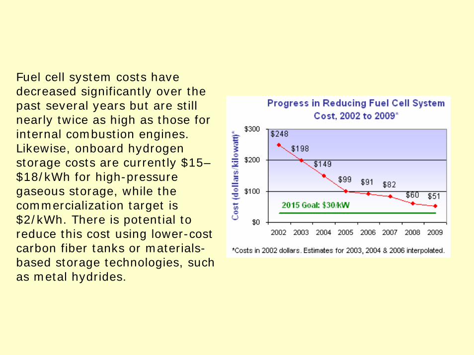
Fuel cell system costs havedecreased significantly over the past several years but are stillnearly twice as high as those forinternal combustion engines.Likewise, onboard hydrogenstorage costs are currently $15–$18/kWh for high-pressuregaseous storage, while the commercialization target is$2/kWh. There is potential toreduce this cost using lower-costcarbon fiber tanks or materials-based storage technologies, suchas metal hydrides.
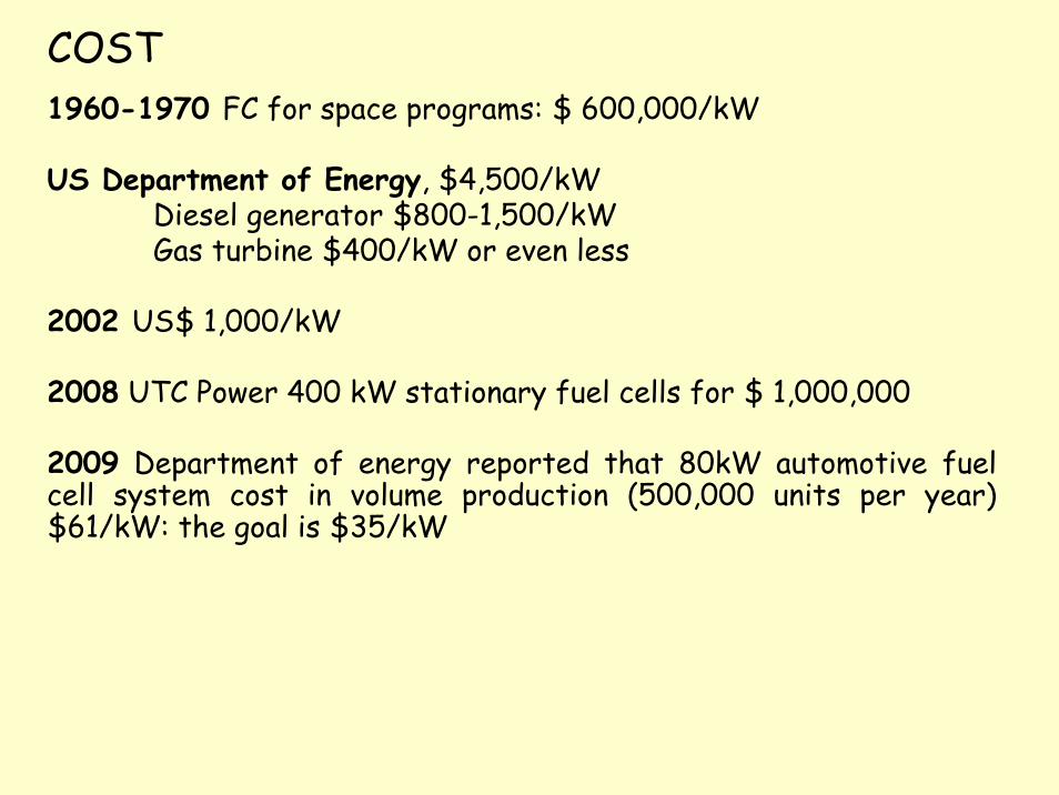
COST1960-1970 FC for space programs: $ 600,000/kW
US Department of Energy, $4,500/kWDiesel generator $800-1,500/kWGas turbine $400/kW or even less
2002 US$ 1,000/kW
2008 UTC Power 400 kW stationary fuel cells for $ 1,000,000
2009 Department of energy reported that 80kW automotive fuel cell system cost in volume production (500,000 units per year) $61/kW: the goal is $35/kW