Embed Size (px)
Citation preview
Fuel Cells
Thomas G. BenjaminJ. David Carter
Argonne National Laboratory
Technology Management Association of Chicago Arlington Heights, IL
February 5, 2007
2
Outline
The US Energy PictureFuel Cells- Definition and HistoryTypes of Fuel CellsPEM Fuel CellsLearning DemonstrationParting ShotsHydrogen StorageResources
3
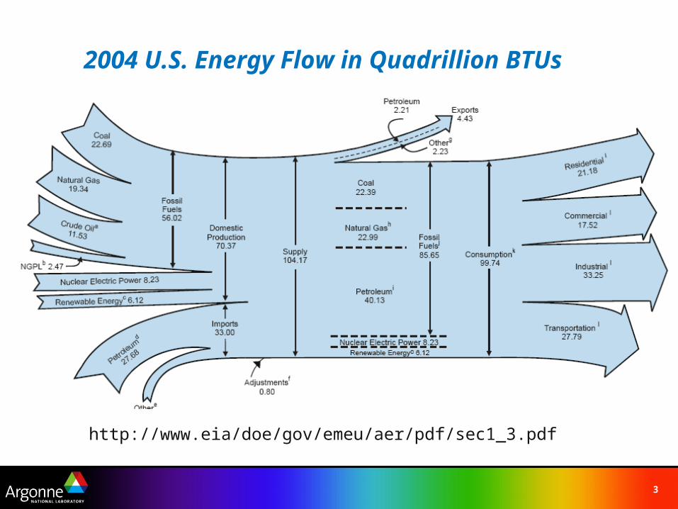
http://www.eia/doe/gov/emeu/aer/pdf/sec1_3.pdf
2004 U.S. Energy Flow in Quadrillion BTUs
4
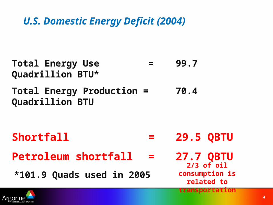
U.S. Domestic Energy Deficit (2004)
Total Energy Use = 99.7 Quadrillion BTU*
Total Energy Production = 70.4 Quadrillion BTU
Shortfall = 29.5 QBTU
Petroleum shortfall = 27.7 QBTU
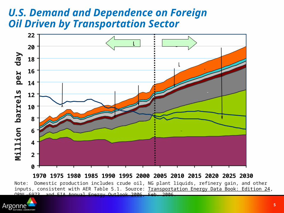
2/3 of oil consumption is related to transportation*101.9 Quads used in 2005
5
U.S. Demand and Dependence on Foreign Oil Driven by Transportation Sector
Note: Domestic production includes crude oil, NG plant liquids, refinery gain, and other inputs, consistent with AER Table 5.1. Source: Transportation Energy Data Book: Edition 24, ORNL-6973, and EIA Annual Energy Outlook 2006, Feb. 2006.
Mill
ion
bar
rels
pe
r d
ay
0
2
4
6
8
10
12
14
16
18
20
22
1970 1975 1980 1985 1990 1995 2000 2005 2010 2015 2020 2025 2030
Marine
Rail
Actual Projection
Cars
Air
Light Trucks
Heavy Vehicles
U.S. Production 1: Crude + NG Plant Liquids + Refinery Gain
Off-Road
U.S. Production 2: Coal Liquids + Other
6
0 1,000 2,000 3,000 4,000 5,000 6,000
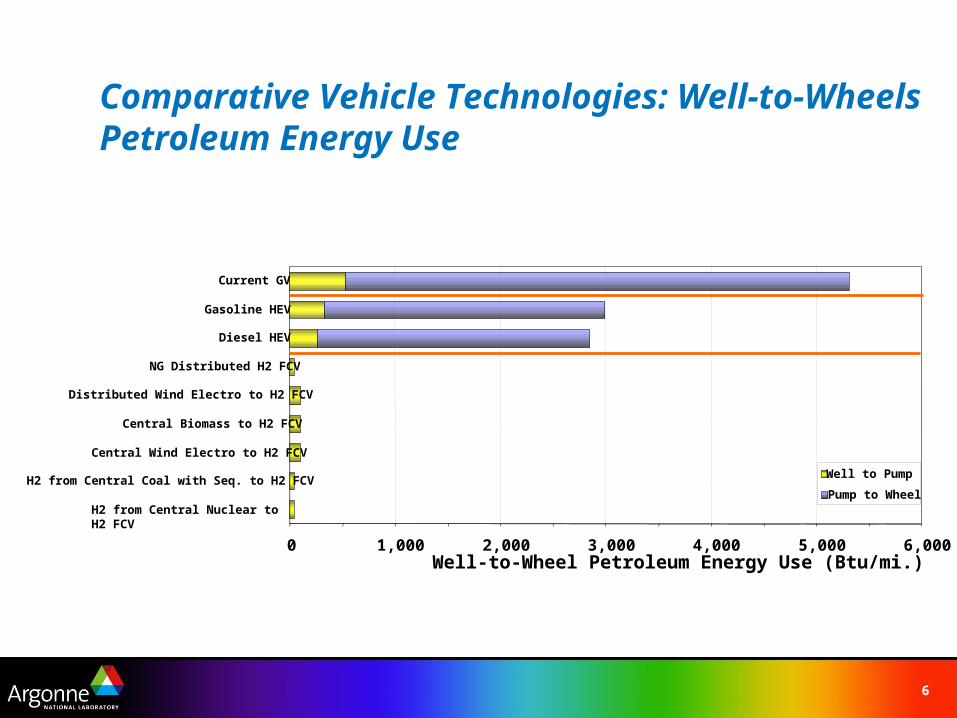
H2 from Central Nuclear to H2 FCV
H2 from Central Coal with Seq. to H2 FCV
Central Wind Electro to H2 FCV
Central Biomass to H2 FCV
Distributed Wind Electro to H2 FCV
NG Distributed H2 FCV
Diesel HEV
Gasoline HEV
Current GV
Well-to-Wheel Petroleum Energy Use (Btu/mi.)
Well to Pump
Pump to Wheel
Comparative Vehicle Technologies: Well-to-Wheels Petroleum Energy Use
7
0 100 200 300 400 500
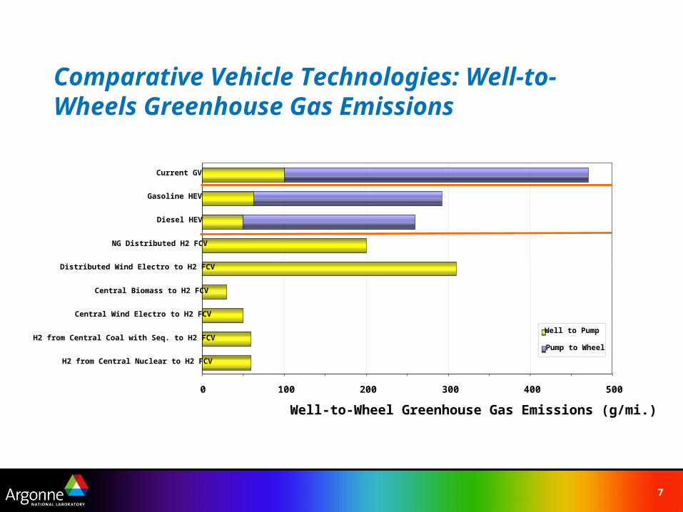
H2 from Central Nuclear to H2 FCV
H2 from Central Coal with Seq. to H2 FCV
Central Wind Electro to H2 FCV
Central Biomass to H2 FCV
Distributed Wind Electro to H2 FCV
NG Distributed H2 FCV
Diesel HEV
Gasoline HEV
Current GV
Well-to-Wheel Greenhouse Gas Emissions (g/mi.)
Well to Pump
Pump to Wheel
Comparative Vehicle Technologies: Well-to-Wheels Greenhouse Gas Emissions
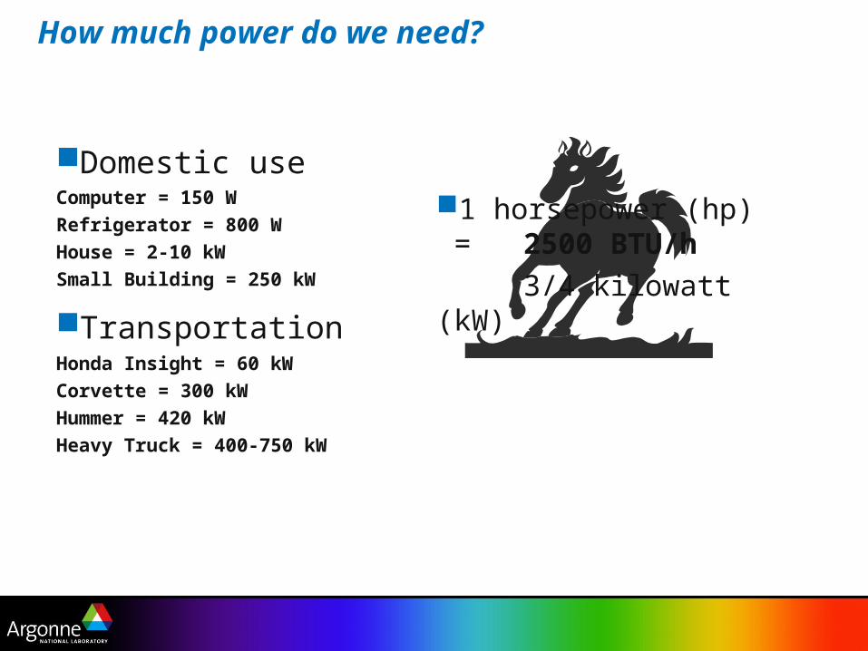
Domestic useComputer = 150 W
Refrigerator = 800 W
House = 2-10 kW
Small Building = 250 kW
TransportationHonda Insight = 60 kW
Corvette = 300 kW
Hummer = 420 kW
Heavy Truck = 400-750 kW
How much power do we need?
1 horsepower (hp) = 2500 BTU/h
3/4 kilowatt (kW)
9
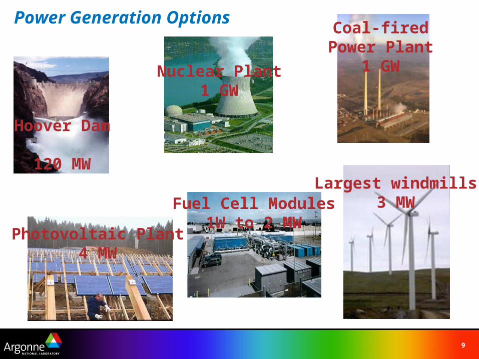
Power Generation Options
Nuclear Plant1 GW
Hoover Dam120 MW
Photovoltaic Plant4 MW
Fuel Cell Modules1W to 2 MW
Largest windmills3 MW
Coal-fired Power Plant
1 GW
10
Outline
The US Energy PictureFuel Cells- History and DefinitionTypes of Fuel CellsPEM Fuel CellsLearning DemonstrationParting ShotsHydrogen StorageResources
11
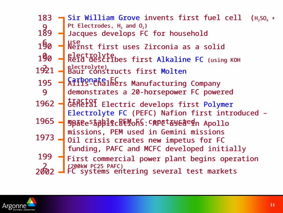
Reid describes first Alkaline FC (using KOH electrolyte)Reid describes first Alkaline FC (using KOH electrolyte)
Sir William Grove invents first fuel cell (H2SO4 + Pt Electrodes, H2 and O2)Sir William Grove invents first fuel cell (H2SO4 + Pt Electrodes, H2 and O2)
Jacques develops FC for household useJacques develops FC for household use
Nernst first uses Zirconia as a solid electrolyteNernst first uses Zirconia as a solid electrolyte
Baur constructs first Molten Carbonate FCBaur constructs first Molten Carbonate FC
Allis-Chalmers Manufacturing Company demonstrates a 20-horsepower FC powered tractorAllis-Chalmers Manufacturing Company demonstrates a 20-horsepower FC powered tractor
General Electric develops first Polymer Electrolyte FC (PEFC) Nafion first introduced – more stable PEM FC constructedGeneral Electric develops first Polymer Electrolyte FC (PEFC) Nafion first introduced – more stable PEM FC constructed
Space applications: AFC used in Apollo missions, PEM used in Gemini missionsSpace applications: AFC used in Apollo missions, PEM used in Gemini missionsOil crisis creates new impetus for FC funding, PAFC and MCFC developed initiallyOil crisis creates new impetus for FC funding, PAFC and MCFC developed initially
First commercial power plant begins operation (200kW PC25 PAFC)First commercial power plant begins operation (200kW PC25 PAFC)
18391839
18961896
19001900
19021902
19211921
19621962
19651965
19731973
19921992
19591959
20022002 FC systems entering several test marketsFC systems entering several test markets
12
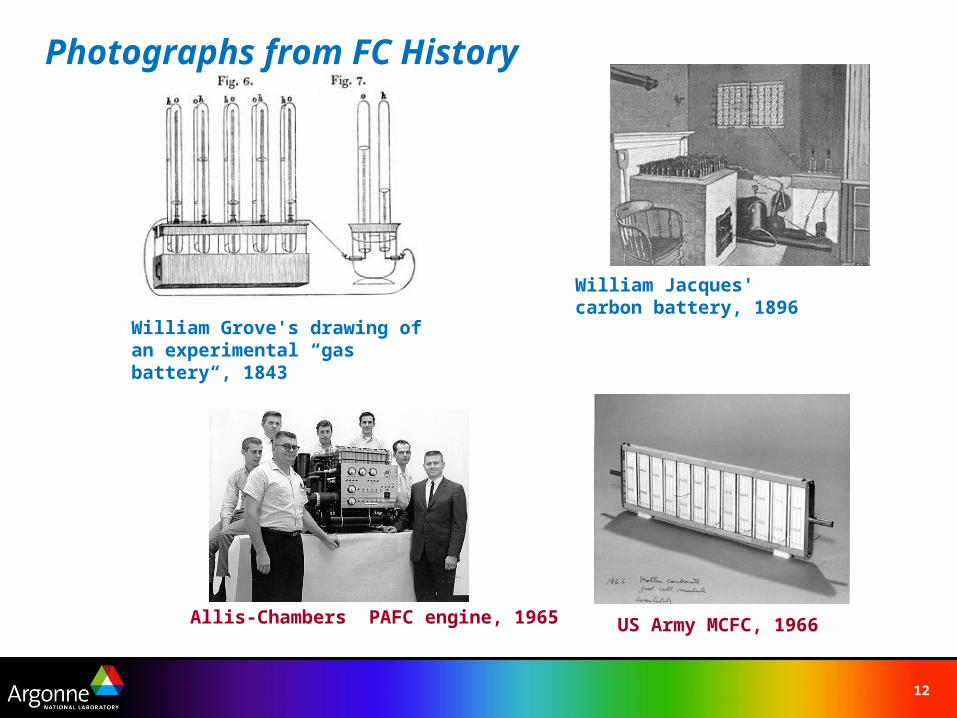
Photographs from FC History
US Army MCFC, 1966Allis-Chambers PAFC engine, 1965
William Grove's drawing of an experimental “gas battery“, 1843
William Jacques' carbon battery, 1896
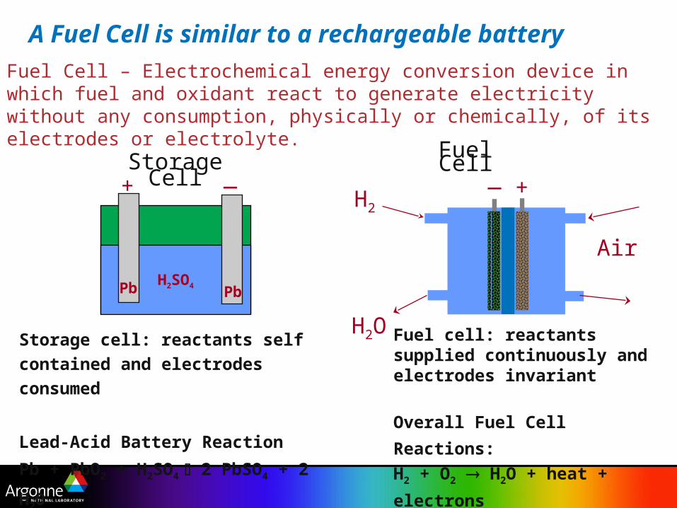
A Fuel Cell is similar to a rechargeable battery
Fuel cell: reactants supplied continuously and electrodes invariant
Overall Fuel Cell Reactions:
H2 + O2 H2O + heat + electrons
Fuel Cell_ +
Air
H2
H2O Storage cell: reactants self contained
and electrodes consumed
Lead-Acid Battery Reaction
Pb + PbO2 + H2SO4 2 PbSO4 + 2 H2O
+ _
H2SO4Pb Pb
Storage Cell
Fuel Cell – Electrochemical energy conversion device in which fuel and oxidant react to generate electricity without any consumption, physically or chemically, of its electrodes or electrolyte.
14
Bip
ola
r P
late
Ca
tho
de
+
An
od
e - Ele
ctr
oly
teH+
H+
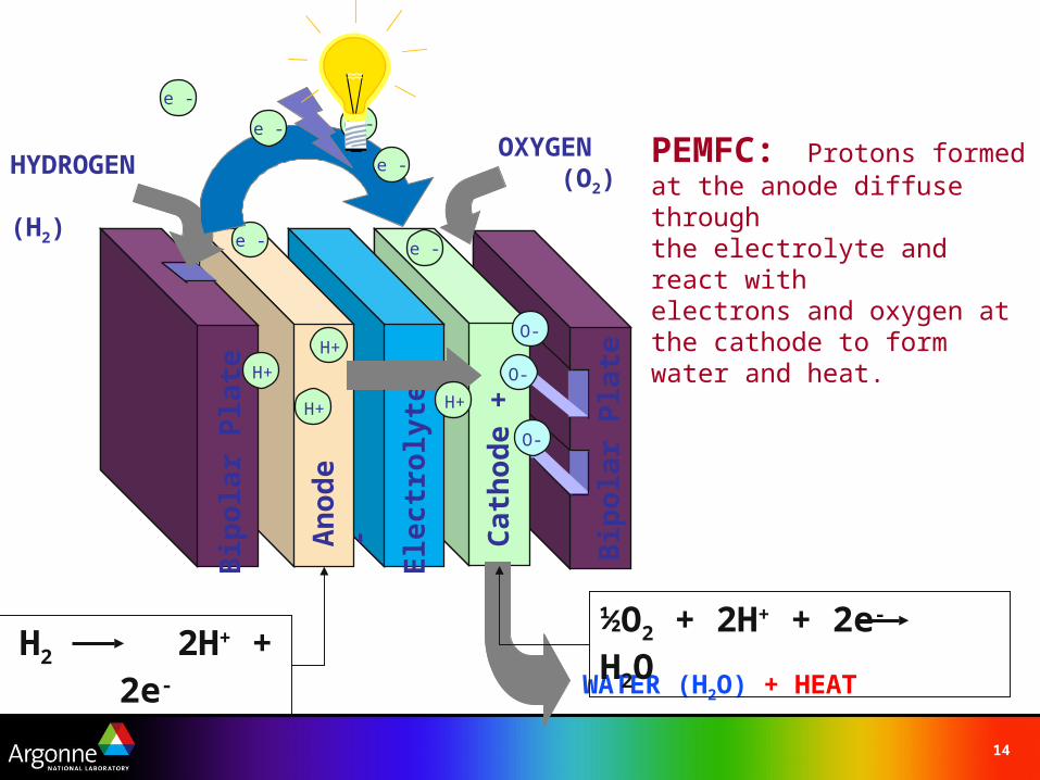
HYDROGEN (H2)
OXYGEN (O2)
Bip
ola
r P
late
O-
O-
e -
H+ O-
e -
e -
e -
e - e -
WATER (H2O) + HEAT
H2 2H+ + 2e-½O2 + 2H+ + 2e- H2O
H+
PEMFC: Protons formedat the anode diffuse throughthe electrolyte and react with electrons and oxygen at the cathode to form water and heat.
15
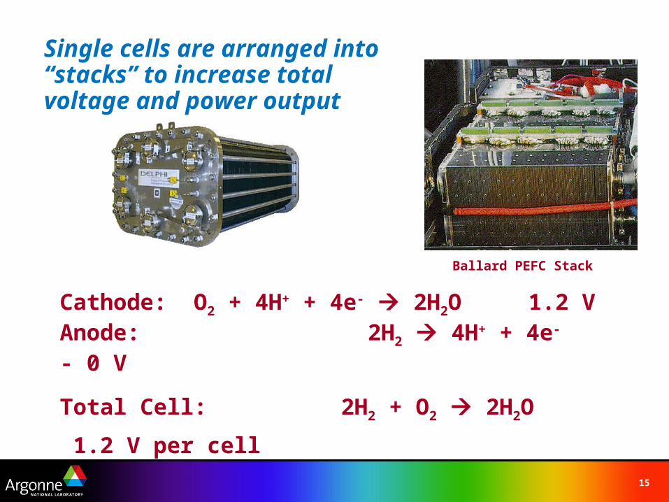
Single cells are arranged into “stacks” to increase total voltage and power output
Cathode: O2 + 4H+ + 4e- 2H2O 1.2 VAnode: 2H2 4H+ + 4e- - 0 V
Total Cell: 2H2 + O2 2H2O 1.2 V per cell
Power = Volts X Amps
Ballard PEFC Stack
16
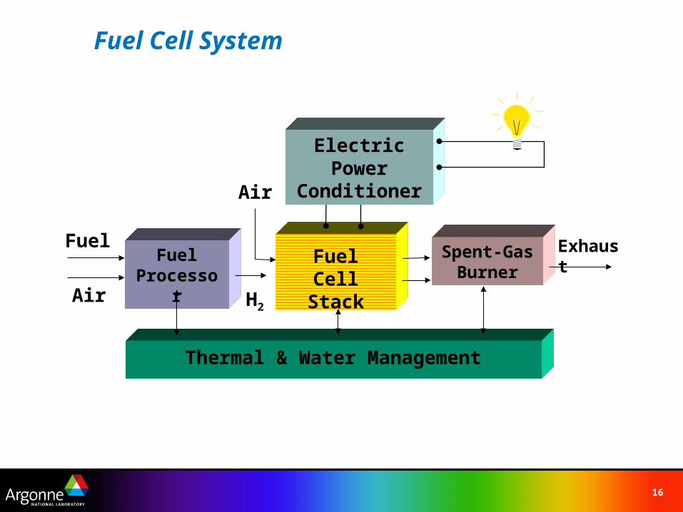
Fuel Cell System
FuelProcessor
Fuel CellStack
Spent-GasBurner
Thermal & Water Management
Air
Air
Fuel
H2
Exhaust
Electric Power Conditioner
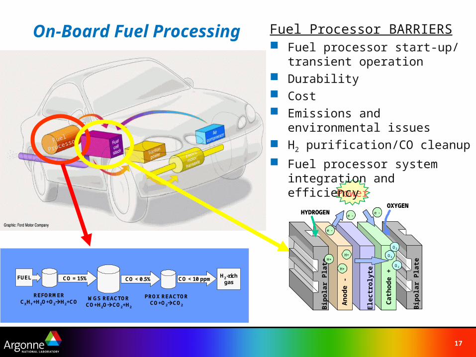
17
Fuel
Processor
H2-rich gas
CO = 15% CO < 10 ppmCO < 0.5%FUEL
REFORMERCXHY+H2O+O2H2+CO
WGS REACTORCO+H2OCO2+H2
PROX REACTORCO+O2CO2
H2-rich gas
CO = 15% CO < 10 ppmCO < 0.5%FUEL
REFORMERCXHY+H2O+O2H2+CO
WGS REACTORCO+H2OCO2+H2
PROX REACTORCO+O2CO2
Power
Bip
ola
r P
late
Cat
ho
de
+
An
od
e -
Ele
ctro
lyte
H+
H+
HYDROGENOXYGEN
Bip
ola
r P
late
e -e -
O2
O2
O2
e -
H+
Bip
ola
r P
late
Bip
ola
r P
late
Cat
ho
de
+
An
od
e -
Ele
ctro
lyte
H+H+
H+H+
HYDROGENOXYGEN
Bip
ola
r P
late
Bip
ola
r P
late
e -e -e -e -
O2O2
O2O2
O2O2
e -e -
H+H+
Fuel Processor BARRIERS Fuel processor start-up/ transient
operation Durability Cost Emissions and environmental
issues H2 purification/CO cleanup
Fuel processor system integration and efficiency
On-Board Fuel Processing
18
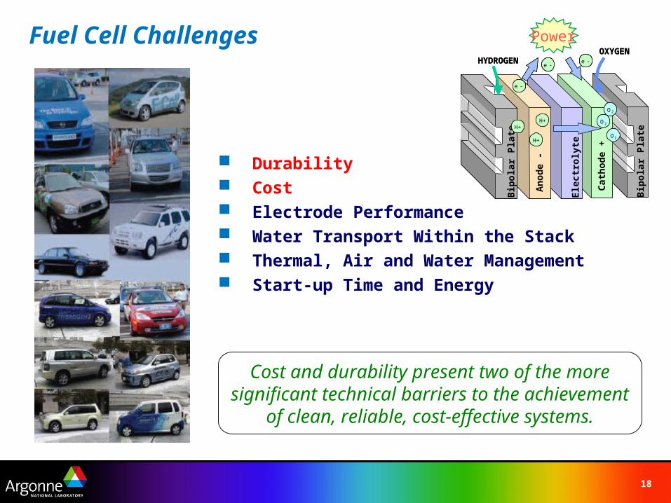
Fuel Cell Challenges
Durability Cost Electrode Performance Water Transport Within the Stack Thermal, Air and Water Management Start-up Time and Energy
Cost and durability present two of the more significant technical barriers to the achievement
of clean, reliable, cost-effective systems.
Bip
ola
r P
late
Cat
ho
de
+
An
od
e -
Ele
ctro
lyte
H+
H+
HYDROGENOXYGEN
Bip
ola
r P
late
e -e -
O2
O2
O2
e -
H+
Bip
ola
r P
late
Bip
ola
r P
late
Cat
ho
de
+
An
od
e -
Ele
ctro
lyte
H+H+
H+H+
HYDROGENOXYGEN
Bip
ola
r P
late
Bip
ola
r P
late
e -e -e -e -
O2O2
O2O2
O2O2
e -e -
H+H+
Power
19
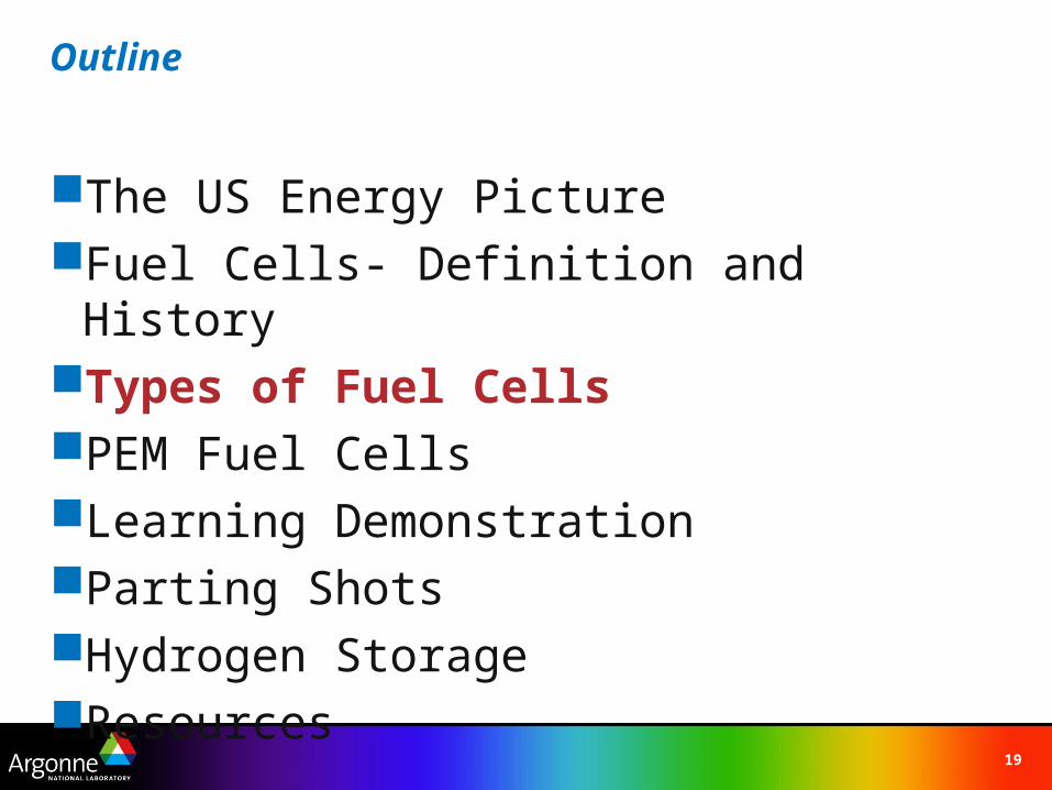
Outline
The US Energy PictureFuel Cells- Definition and HistoryTypes of Fuel CellsPEM Fuel CellsLearning DemonstrationParting ShotsHydrogen StorageResources
20
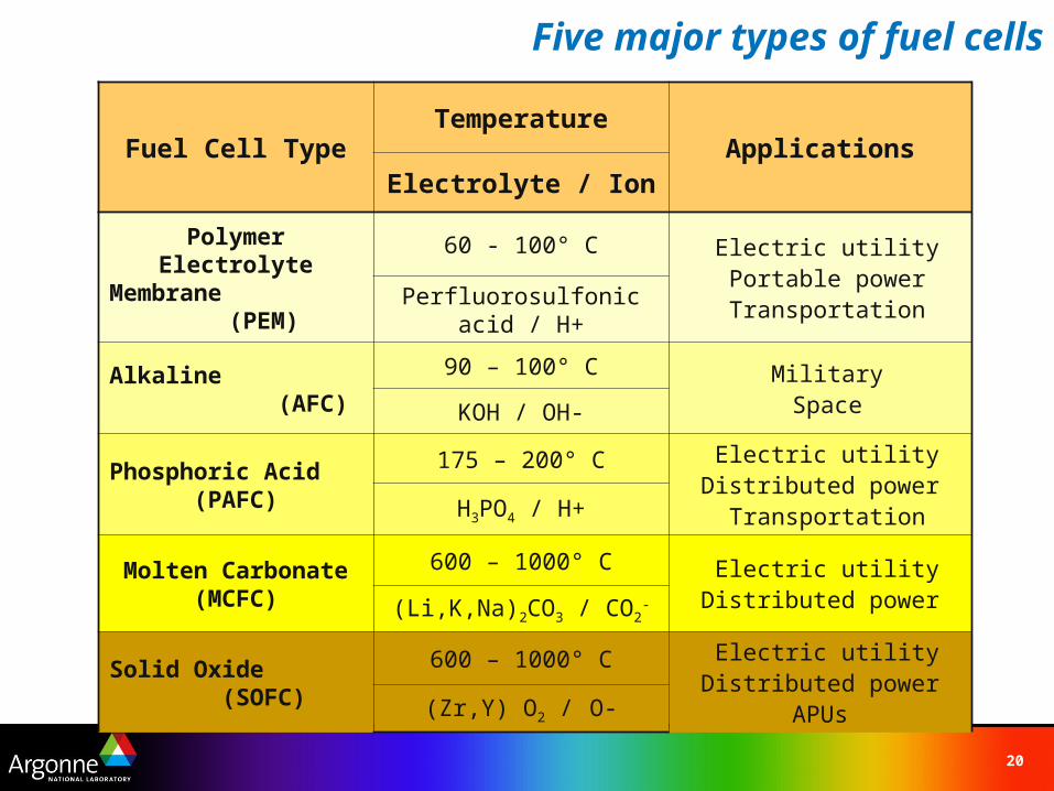
Five major types of fuel cells
Fuel Cell TypeTemperature
ApplicationsElectrolyte / Ion
Polymer Electrolyte Membrane
(PEM)
60 - 100° C Electric utility Portable power TransportationPerfluorosulfonic acid / H+
Alkaline (AFC)
90 – 100° C Military SpaceKOH / OH-
Phosphoric Acid (PAFC)
175 – 200° C Electric utilityDistributed power TransportationH3PO4 / H+
Molten Carbonate (MCFC)
600 – 1000° C Electric utilityDistributed power(Li,K,Na)2CO3 / CO2
-
Solid Oxide (SOFC)
600 – 1000° C Electric utilityDistributed power
APUs(Zr,Y) O2 / O-
21
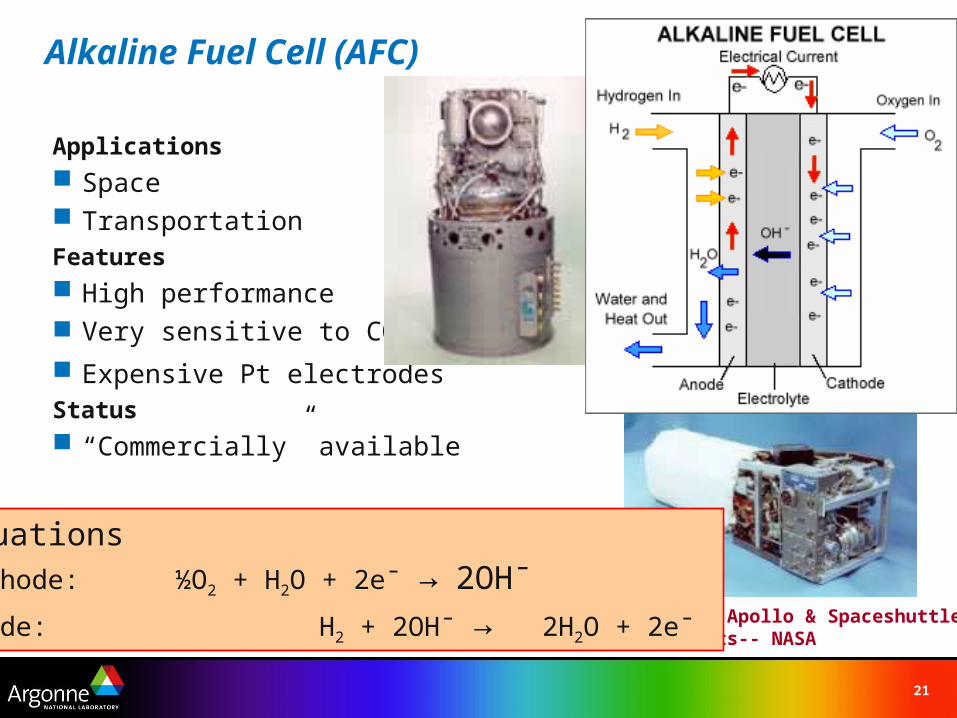
Alkaline Fuel Cell (AFC)
Applications
Space TransportationFeatures
High performance Very sensitive to CO2
Expensive Pt electrodesStatus
“Commercially” available
AFCs from Apollo & SpaceshuttleSpacecrafts-- NASA
EquationsCathode: ½O2 + H2O + 2e¯ → 2OH¯
Anode: H2 + 2OH¯ → 2H2O + 2e¯
22
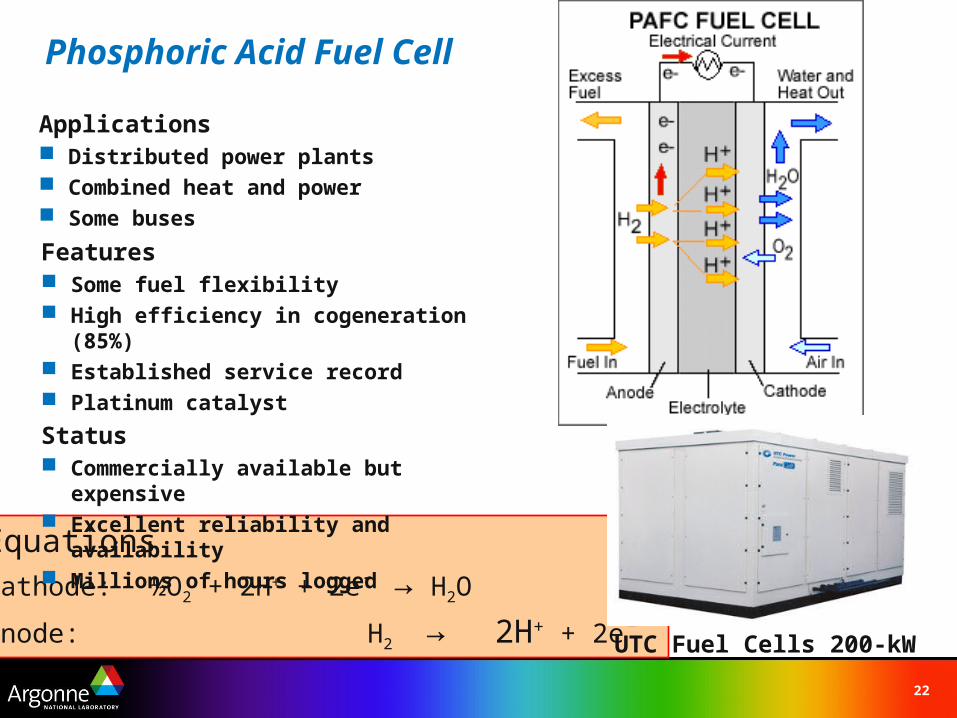
Phosphoric Acid Fuel Cell
EquationsCathode: ½O2 + 2H+ + 2e¯ → H2O
Anode: H2 → 2H+ + 2e¯
Applications Distributed power plants Combined heat and power Some buses
Features Some fuel flexibility High efficiency in cogeneration (85%) Established service record Platinum catalyst
Status Commercially available but expensive Excellent reliability and availability Millions of hours logged
UTC Fuel Cells 200-kW
23
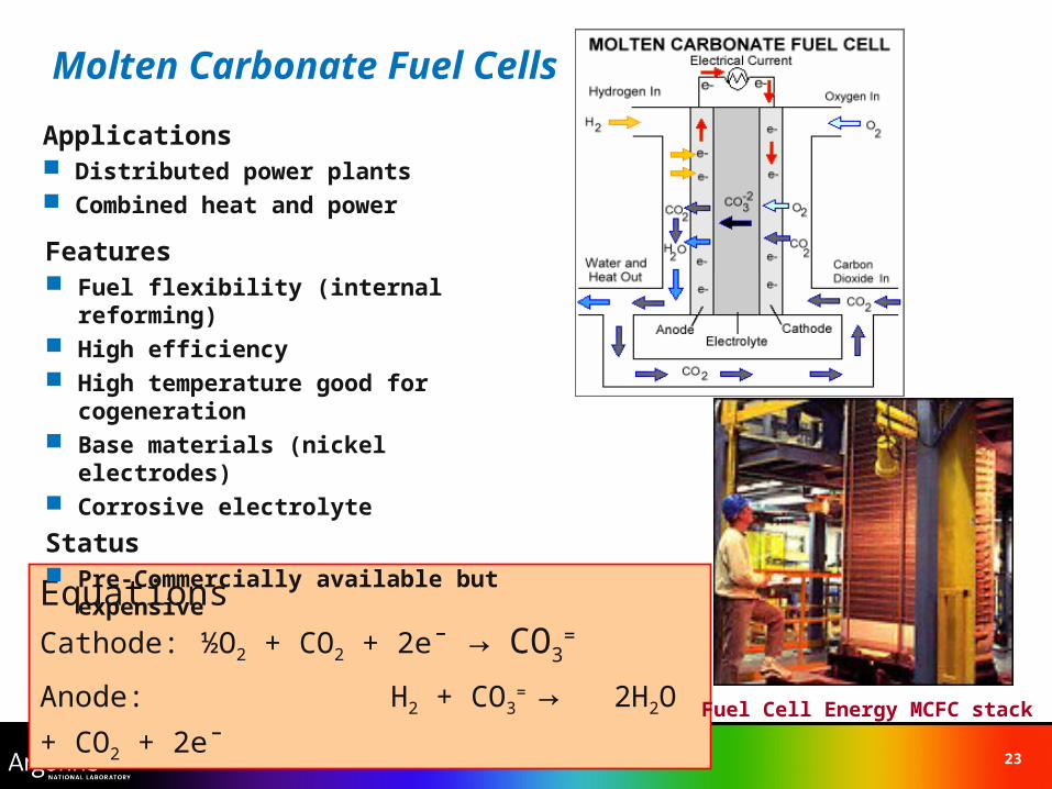
EquationsCathode: ½O2 + CO2 + 2e¯ → CO3
=
Anode: H2 + CO3= → 2H2O + CO2 +
2e¯ Fuel Cell Energy MCFC stack
Molten Carbonate Fuel Cells
Applications Distributed power plants Combined heat and power
Features Fuel flexibility (internal reforming) High efficiency High temperature good for cogeneration Base materials (nickel electrodes) Corrosive electrolyte
Status Pre-Commercially available but expensive
24
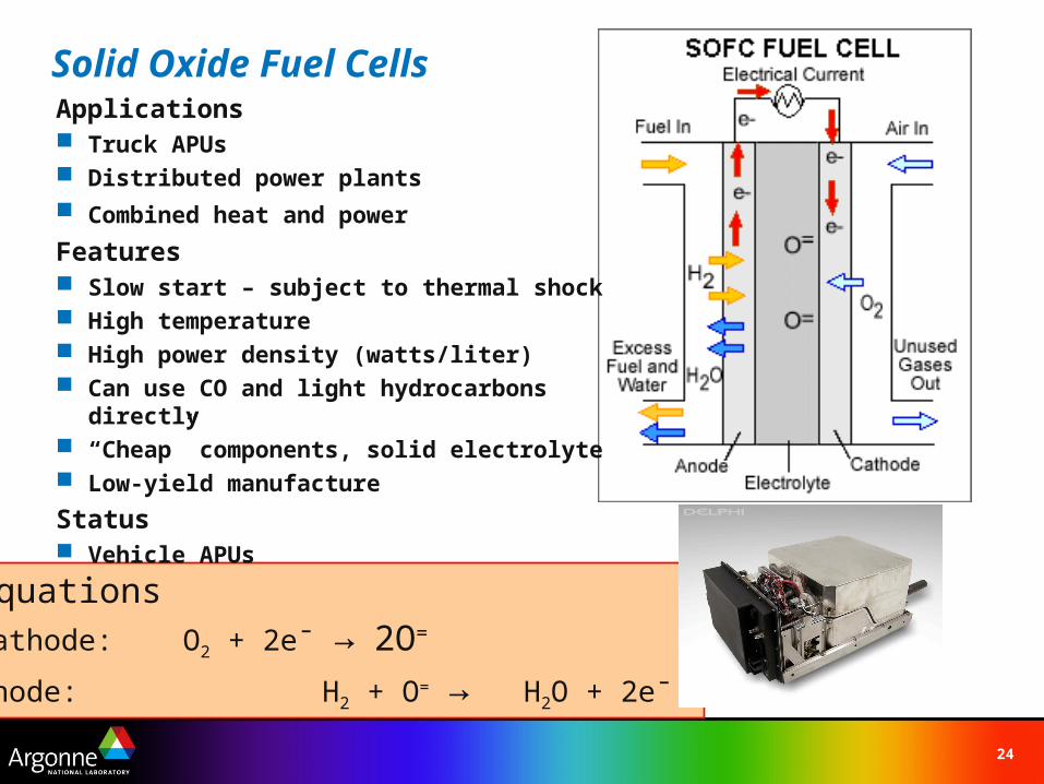
EquationsCathode: O2 + 2e¯ → 2O=
Anode: H2 + O= → H2O + 2e¯
Solid Oxide Fuel CellsApplications Truck APUs Distributed power plants Combined heat and power
Features Slow start – subject to thermal shock High temperature High power density (watts/liter) Can use CO and light hydrocarbons directly “Cheap” components, solid electrolyte Low-yield manufacture
Status Vehicle APUs
25
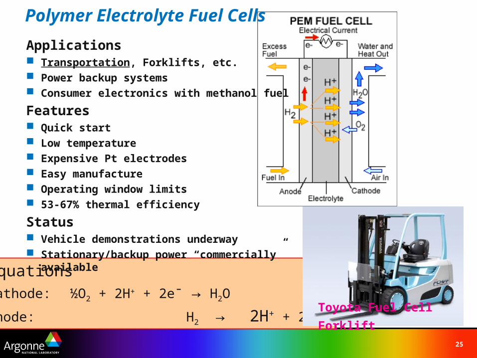
EquationsCathode: ½O2 + 2H+ + 2e¯ → H2O
Anode: H2 → 2H+ + 2e¯
Polymer Electrolyte Fuel Cells
Applications Transportation, Forklifts, etc. Power backup systems Consumer electronics with methanol fuel
Features Quick start Low temperature Expensive Pt electrodes Easy manufacture Operating window limits 53-67% thermal efficiency
Status Vehicle demonstrations underway Stationary/backup power “commercially” available
Toyota Fuel Cell Forklift
26
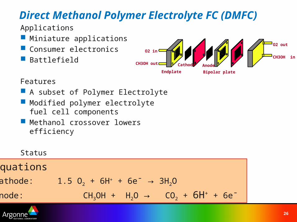
Direct Methanol Polymer Electrolyte FC (DMFC)Applications Miniature applications Consumer electronics Battlefield
Features A subset of Polymer Electrolyte Modified polymer electrolyte fuel cell
components Methanol crossover lowers efficiency
Status Pre-Alpha to Beta testing
Endplate
O2 in
CH3OH out Cathode Anode
Bipolar plate
O2 out
CH3OH in
EquationsCathode: 1.5 O2 + 6H+ + 6e¯ → 3H2O
Anode: CH3OH + H2O → CO2 + 6H+ + 6e¯
27
Outline
The US Energy PictureFuel Cells- Definition and HistoryTypes of Fuel CellsPEM Fuel CellsLearning DemonstrationParting ShotsHydrogen StorageResources
28
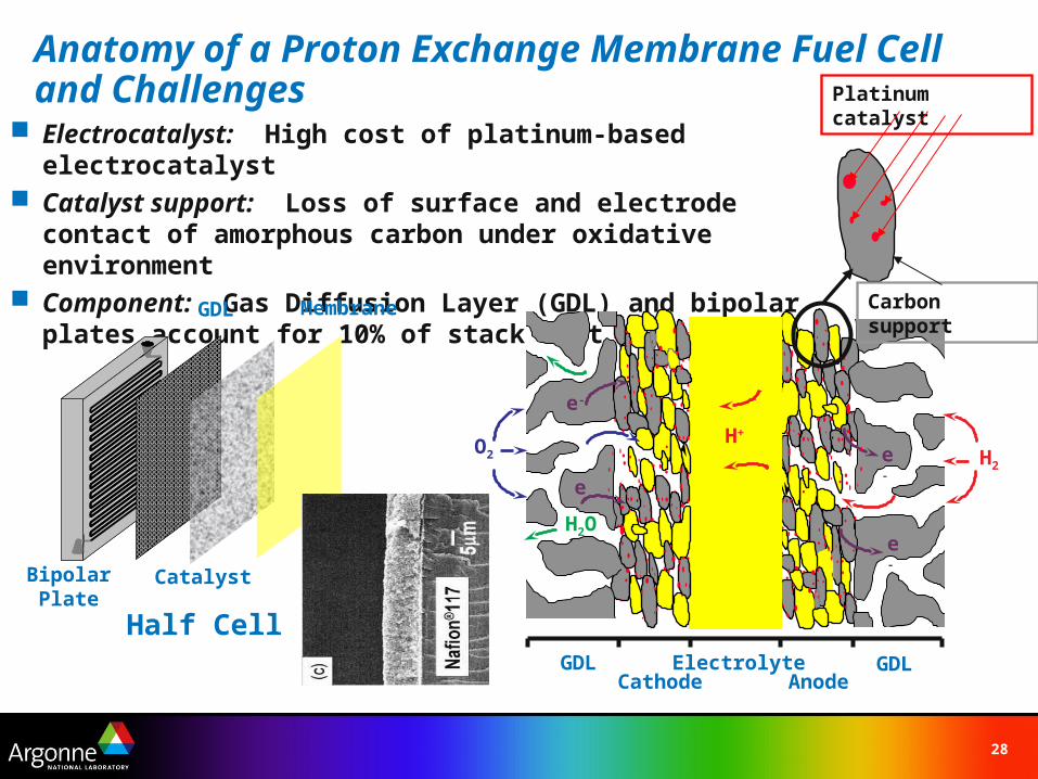
Anatomy of a Proton Exchange Membrane Fuel Cell and Challenges
Electrocatalyst: High cost of platinum-based electrocatalyst Catalyst support: Loss of surface and electrode contact of
amorphous carbon under oxidative environment Component: Gas Diffusion Layer (GDL) and bipolar plates
account for 10% of stack cost
ElectrolyteAnode
GDLCathode
GDL
H2 e-
e-
H+
H2
e-
e-
O2
H2O
H2
Membrane
Catalyst
GDL
BipolarPlate
Half Cell
Carbon support
Platinum catalyst
29
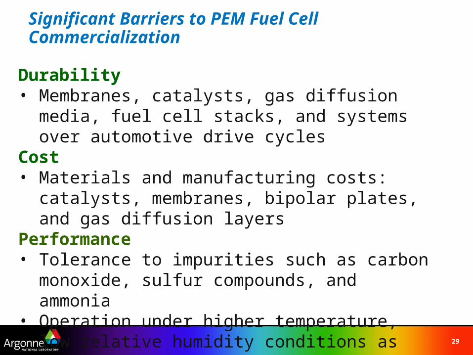
Significant Barriers to PEM Fuel Cell Commercialization
Durability• Membranes, catalysts, gas diffusion media, fuel cell
stacks, and systems over automotive drive cyclesCost• Materials and manufacturing costs: catalysts,
membranes, bipolar plates, and gas diffusion layers Performance• Tolerance to impurities such as carbon monoxide,
sulfur compounds, and ammonia• Operation under higher temperature, low relative
humidity conditions as well as sub-freezing conditions
30
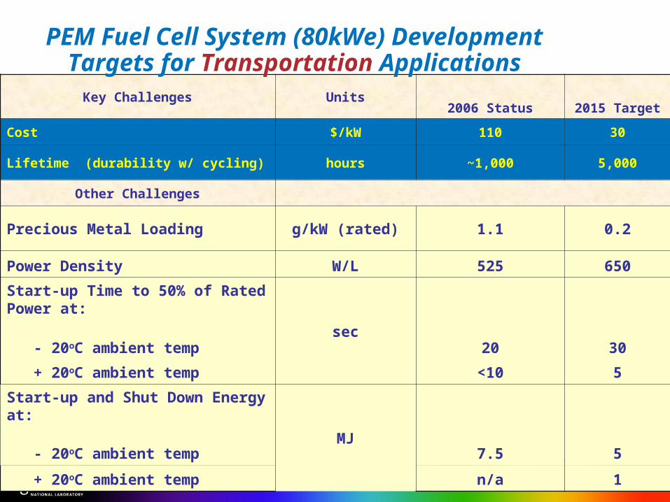
Key Challenges Units2006 Status 2015 Target
Cost $/kW 110 30
Lifetime (durability w/ cycling) hours ~1,000 5,000
Other Challenges
Precious Metal Loading g/kW (rated) 1.1 0.2
Power Density W/L 525 650
Start-up Time to 50% of Rated Power at:
- 20oC ambient temp sec 20 30
+ 20oC ambient temp <10 5
Start-up and Shut Down Energy at: - 20oC ambient temp MJ 7.5 5
+ 20oC ambient temp n/a 1
PEM Fuel Cell System (80kWe) Development Targets for Transportation Applications
31
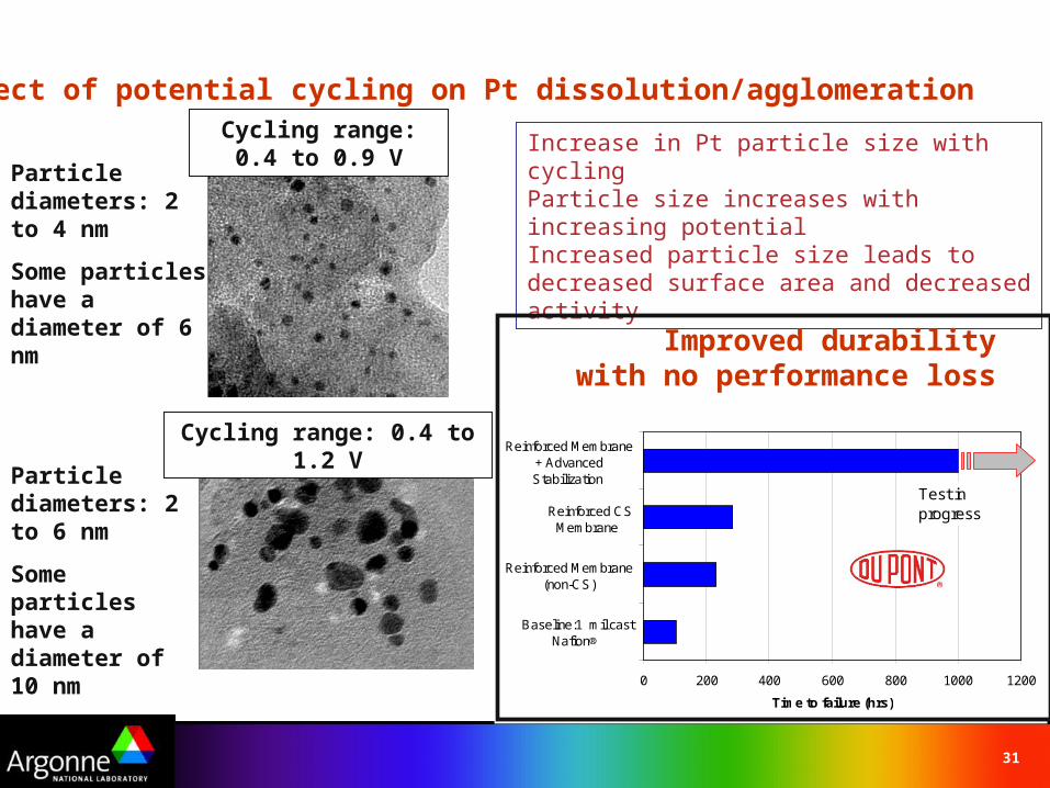
Cycling range: 0.4 to 0.9 V
Particle diameters: 2 to 4 nm
Some particles have a diameter of 6 nm
Particle diameters: 2 to 6 nm
Some particles have a diameter of 10 nm
Cycling range: 0.4 to 1.2 V
Effect of potential cycling on Pt dissolution/agglomeration
Increase in Pt particle size with cyclingParticle size increases with increasing potential Increased particle size leads to decreased surface area and decreased activity
0 200 400 600 800 1000 1200
Baseline:1 mil castNafion®
Reinforced Membrane(non-CS)
Reinforced CSMembrane
Reinforced Membrane+ AdvancedStabilization
Time to failure (hrs)
Test in progress
Improved durabilitywith no performance loss
32
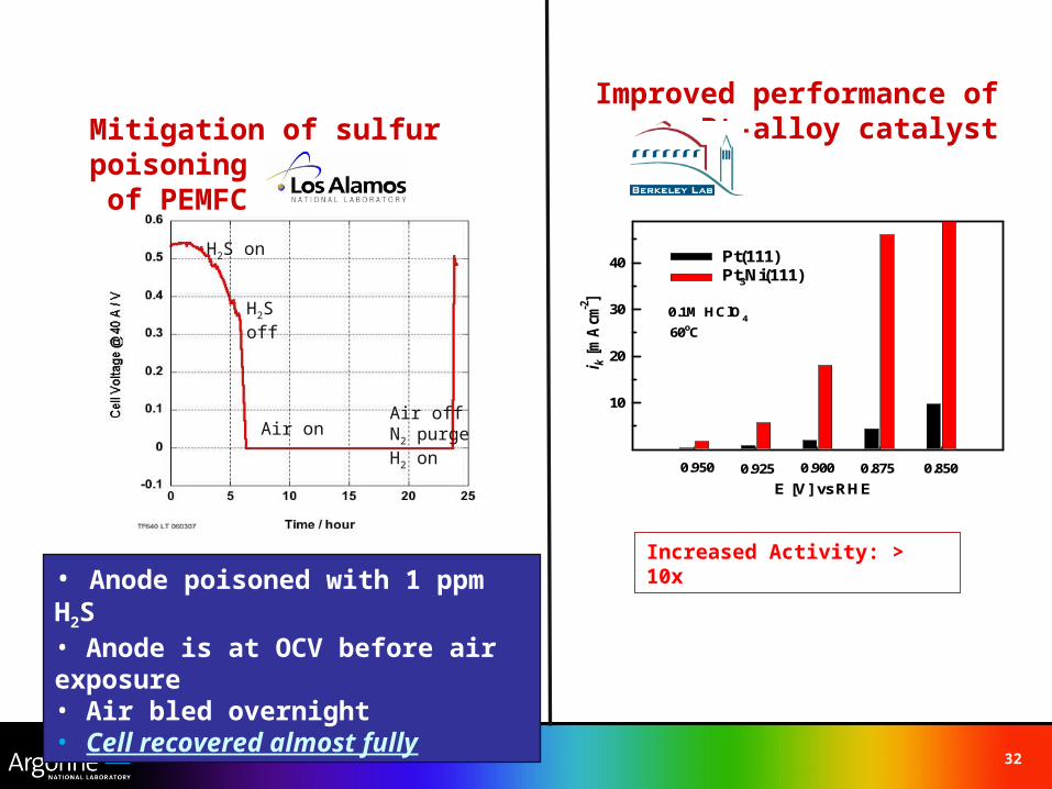
Mitigation of sulfur poisoning of PEMFC
LANL
H2S on
H2S off
Air onAir offN2 purgeH2 on
• Anode poisoned with 1 ppm H2S• Anode is at OCV before air exposure• Air bled overnight• Cell recovered almost fully
Improved performance ofPt-alloy catalyst
0.1M HClO4
i k [
mA
cm-2
]
10
20
30
40 Pt(111)Pt3Ni(111)
60oC
0.950 0.925 0.900 0.875 0.850
E [V] vs RHE
Increased Activity: > 10x
33
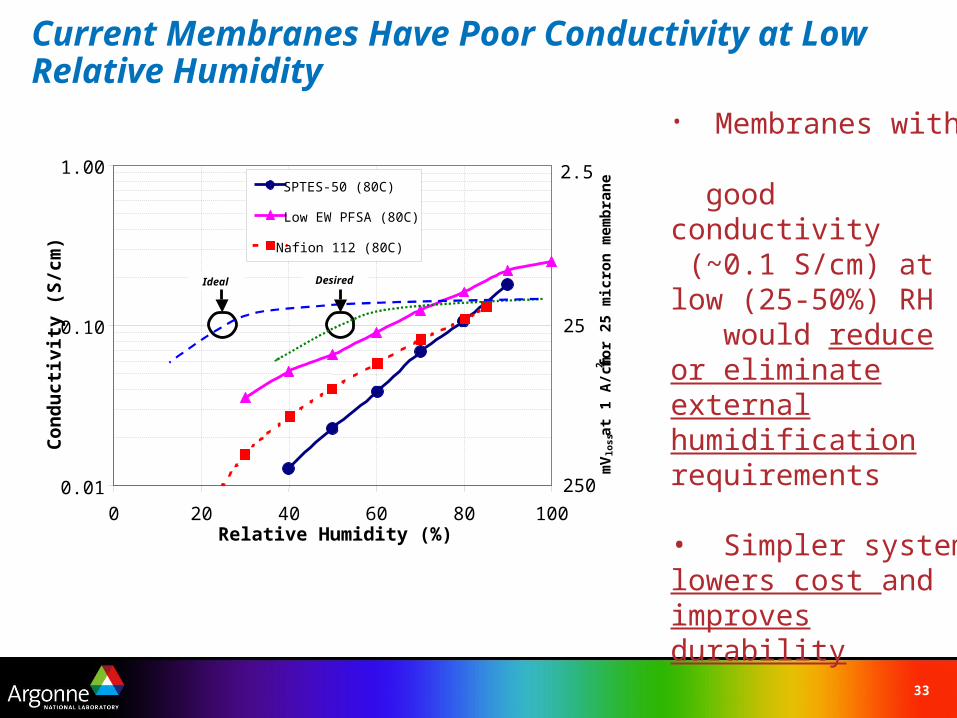
Current Membranes Have Poor Conductivity at Low Relative Humidity
• Membranes with good conductivity (~0.1 S/cm) at low (25-50%) RH would reduce or eliminate externalhumidification requirements
• Simpler system lowers cost and improves durability
200.01
0.10
1.00
0 40 60 80 100Relative Humidity (%)
Co
nd
uct
ivit
y (S
/cm
)
SPTES-50 (80C)
Low EW PFSA (80C)
Nafion 112 (80C)
Ideal Desired
mV
loss
at
1 A
/cm
2 fo
r 25
mic
ron
mem
bra
ne
250
25
2.5
34
Outline
The US Energy PictureFuel Cells- Definition and HistoryTypes of Fuel CellsPEM Fuel CellsLearning DemonstrationParting ShotsHydrogen StorageResources
35
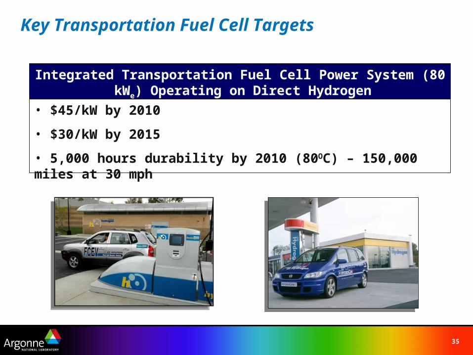
Key Transportation Fuel Cell Targets
Integrated Transportation Fuel Cell Power System (80 kWe) Operating on Direct Hydrogen
• $45/kW by 2010
• $30/kW by 2015
• 5,000 hours durability by 2010 (80OC) – 150,000 miles at 30 mph
36
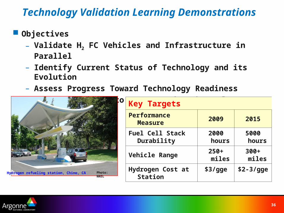
Objectives
– Validate H2 FC Vehicles and Infrastructure in Parallel
– Identify Current Status of Technology and its Evolution– Assess Progress Toward Technology Readiness
– Provide Feedback to H2 Research and Development
Key Targets
Performance Measure 2009 2015
Fuel Cell Stack Durability
2000 hours
5000 hours
Vehicle Range250+ miles
300+ miles
Hydrogen Cost at Station
$3/gge $2-3/ggePhoto: NRELHydrogen refueling station, Chino, CA
Technology Validation Learning Demonstrations
37
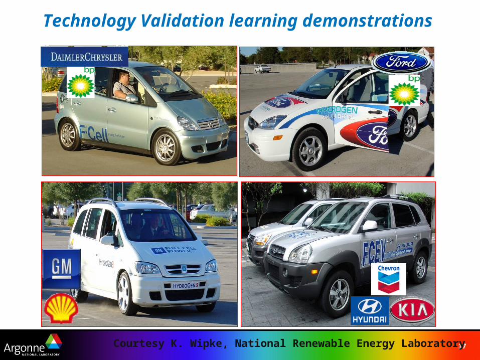
Technology Validation learning demonstrations
Courtesy K. Wipke, National Renewable Energy Laboratory
38
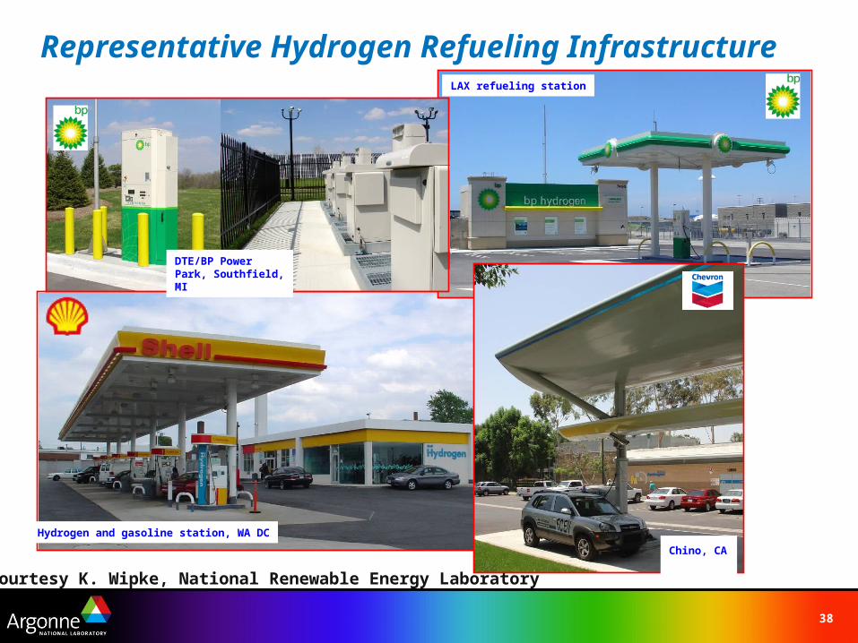
Representative Hydrogen Refueling InfrastructureLAX refueling station
Hydrogen and gasoline station, WA DC
Chino, CA
DTE/BP Power Park, Southfield, MI
Courtesy K. Wipke, National Renewable Energy Laboratory
39
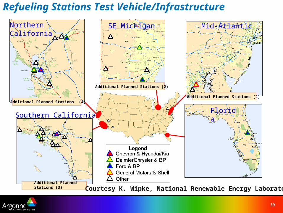
Refueling Stations Test Vehicle/Infrastructure
09-22-06
Northern California
Southern CaliforniaFlorida
Additional Planned Stations (3)
Additional Planned Stations (4)
SE Michigan Mid-Atlantic
Additional Planned Stations (2)
Additional Planned Stations (2)
Courtesy K. Wipke, National Renewable Energy Laboratory
40
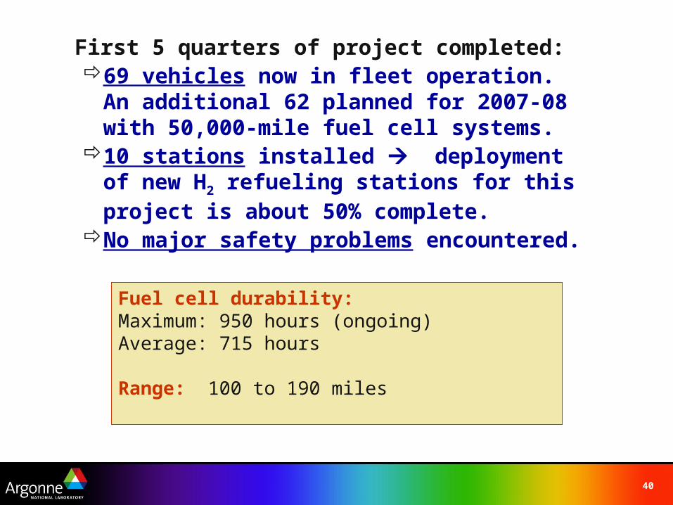
First 5 quarters of project completed:69 vehicles now in fleet operation. An
additional 62 planned for 2007-08 with 50,000-mile fuel cell systems.
10 stations installed deployment of new H2 refueling stations for this project is about 50% complete.
No major safety problems encountered.
Fuel cell durability: Maximum: 950 hours (ongoing)Average: 715 hours
Range: 100 to 190 miles
41
Outline
The US Energy PictureFuel Cells- Definition and HistoryTypes of Fuel CellsPEM Fuel CellsLearning DemonstrationParting Shots (of fuel cells)Hydrogen StorageResources
42
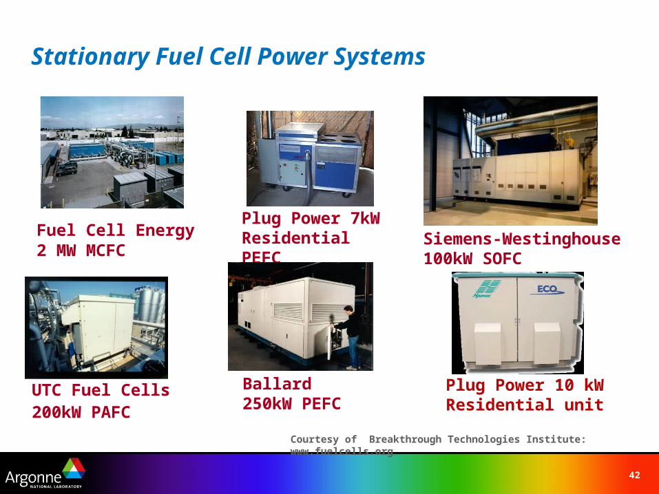
Stationary Fuel Cell Power Systems
Fuel Cell Energy 2 MW MCFC
Siemens-Westinghouse 100kW SOFC
UTC Fuel Cells 200kW PAFC
Ballard 250kW PEFC
Plug Power 7kW Residential PEFC
Plug Power 10 kW Residential unit
Courtesy of Breakthrough Technologies Institute: www.fuelcells.org
43
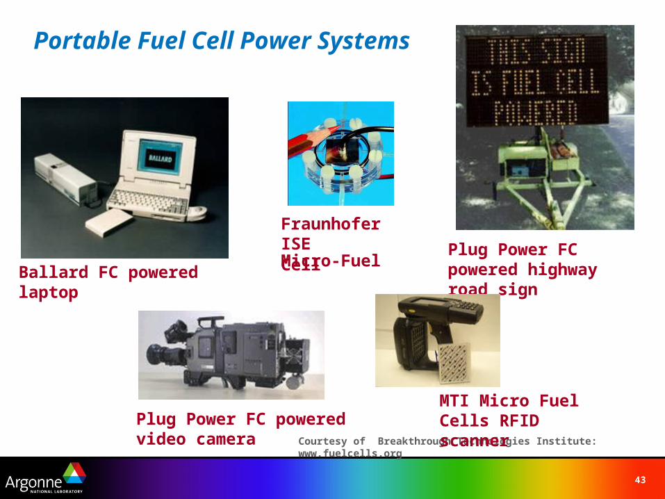
Portable Fuel Cell Power Systems
Plug Power FC powered highway road signBallard FC powered laptop
Plug Power FC powered video camera
Fraunhofer ISE Micro-Fuel Cell
Courtesy of Breakthrough Technologies Institute: www.fuelcells.org
MTI Micro Fuel Cells RFID scanner
44
Outline
The US Energy PictureFuel Cells- Definition and HistoryTypes of Fuel CellsPEM Fuel CellsLearning DemonstrationParting Shots (of fuel cells)Hydrogen StorageResources
45
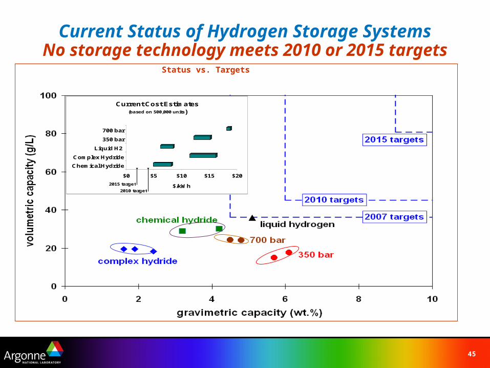
Current Status of Hydrogen Storage SystemsNo storage technology meets 2010 or 2015 targets
$0 $5 $10 $15 $20
$/kWh
Chemical Hydride
Complex Hydride
Liquid H2
350 bar
700 bar
Current Cost Estimates(based on 500,000 units)
2010 target
2015 target
Status vs. Targets
46
Outline
The US Energy PictureFuel Cells- Definition and HistoryTypes of Fuel CellsPEM Fuel CellsLearning DemonstrationHydrogen storageResources

47
For More Informationwww.hydrogen.energy.gov Fact sheets available in the web
site library
Find....
The latest news, reports & announcements
Status information about program solicitations
Fuel cell and hydrogen "basics" information
48
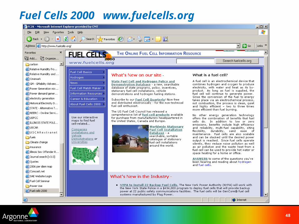
Fuel Cells 2000 www.fuelcells.org

49
US Fuel Cell Council www.usfcc.com
50
Thank You for your attention
Fuel Cells
Coming to an application near you