Embed Size (px)
Citation preview
JSL1
Fuel Cell Current Ripple Reduction with Active Control Technique
Presented byDr. Jih-Sheng (Jason) Lai
Virginia Polytechnic Institute and State UniversityFuture Energy Electronics Center
January 27 – 28, 2005SECA Core Technology Program Review Meeting
Tampa, Florida
DOE SECA Project #: DE-FC26-02NT41567Program Manager: Don Collins of NETL
JSL2
Outline
1. Review of V6 DC-DC converter 2. Prototype Development3. Current Ripple Reduction4. Summary of V6 Converter Prototype5. Accomplishments and Future Work

JSL3
Block Diagram of the SOFC Power Plant
• Fuel cell output or converter input is low-voltage DC with a wide-range variation
• Plant output is high-voltage ac• Multiple-stage power conversions including
isolation are needed
DC-ACLF-HF
AC-ACLV-HV
AC-DCHV-HV
DC-ACHV-HV
DC-ACInverter
+Filter
SOFCAC-DC
Rectifier+
FilterVin
+
–
+
–
BridgeConverter
HFXformer
SECA DC/DC converter
400 V 120/240V
JSL4
Major Issues Associated with the DC/DC Converter
• Cost• Efficiency• Reliability• Ripple current• Transient response along with auxiliary
energy storage requirement• Communication with fuel cell controller• Electromagnetic interference (EMI) emission

JSL5
Virginia Tech Approaches
• Efficiency improvement to reduce fuel consumption
• V6 multiphase control to reduce passive components for cost reduction
• Ripple current elimination to reduce size of fuel cell stack
• Soft start and current control to reduce the inrush current so as to improve reliability
• Soft switching to reduce EMI
JSL6
State-of-the-Art Full-Bridge Converter
1 : n
HF ACXformer
Rectifier+LC filter
Act
ive
Load
Sol
id-O
xide
Fue
l Cel
l
Full-bridge converter
20V>250A
400V5 kW

JSL7
Full-Bridge Converter with Paralleled Devices to Achieve the Desired Efficiency
Load6x 6x
• With 6 devices in parallel, the two-leg converter can barely achieve 95% efficiency
• Problems are additional losses in parasitic components, voltage clamp, interconnects, filter inductor, transformer, diodes, etc.
Voltage clampSol
id-O
xide
Fue
l Cel
l20V250A
JSL8
Circuit Diagram of the Proposed V6 Converter
Sol
id-O
xide
Fue
l Cel
l
Act
ive
Load
Rectifier+LC filterSix-phase bridge converter
HF ACXformer

JSL9
Key Features of the V6 Converter
• Double output voltage reduce turns ratio and associated leakage inductance
• No overshoot and ringing on primary side device voltage
• DC link inductor current ripple elimination cost and size reduction on inductor
• Secondary voltage overshoot reduction cost and size reduction with elimination of voltage clamping
• Significant EMI reduction cost reduction on EMI filter• Soft switching over a wide load range• High efficiency ~97%• Low device temperature High reliability
JSL10
Efficiency Measurement Results
80%82%84%86%88%90%92%94%96%98%
100%
0 1000 2000 3000 4000Output power (W)
Experimental data and trend line
• Measurement error: within 1%• Heat sink temperature rise:
<20°C at 2kW with natural convection
Effi
cien
cy
75%
80%
85%
90%
95%
100%
0 500 1000 1500 2000 2500Output Power (W)
Effic
ienc
y
Phase-II V6-Converter Efficiency (calibrated)
Phase-I Efficiency Measured Results

JSL11
Waveform Comparison between Full-Bridge and V6 Converters
Full Bridge Converter V6 Converter
iL
iLvd
vd
• Secondary inductor current is ripple-less; and in principle, no dc link inductor is needed
• Secondary voltage swing is eliminated with <40% voltage overshoot as compared to 250%
JSL12
Schematic Circuit Diagrams
Power boardGate drive board
Control boardDigital board
Interface board
JSL13
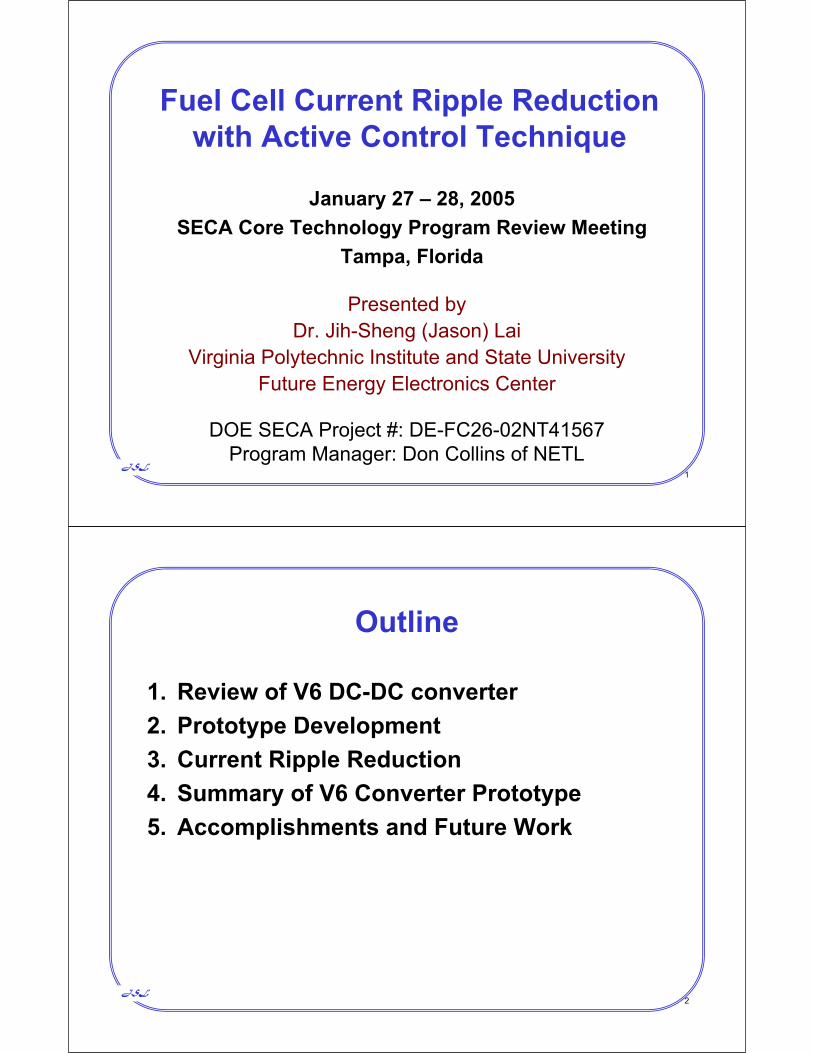
Photographs of V6-Converter Together with DC-AC Inverter Prototype
Front View Rear View
ConverterInverter
JSL14
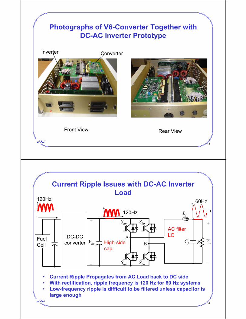
Current Ripple Issues with DC-AC Inverter Load
Lf
Cf RA
BVdc
+
–
Sap
San Sbn
Sbp
Vo
+
–
60Hz
120Hz
• Current Ripple Propagates from AC Load back to DC side• With rectification, ripple frequency is 120 Hz for 60 Hz systems• Low-frequency ripple is difficult to be filtered unless capacitor is
large enough
AC filter LC
High-sidecap.
DC-DCconverter
120Hz
FuelCell

JSL15
AC Current Ripple Problems• Inverter AC current ripple propagates back to fuel
cell• Fuel cell requires a higher current handling
capability Cost penalty to fuel cell stack• Ripple current can cause hysteresis losses and
subsequently more fuel consumption Costpenalty to fuel consumption
• State-of-the-art solutions are adding more capacitors or adding an external active filters Size and cost penalty
• Virginia Tech solution is to use existing V6 converter with active ripple cancellation technique to eliminate the ripple No penalty
JSL16
Circuit Model for AC Current Ripple
N:1Iin
Vin Iload
Rs Lf
Vdc+
–
Ip Is
iin/N
iload
N2Rs Lfip/N is
DC Model
AC Ripple ModelCin/N2
N2RCin
CinRCin
Cf
RCf
Cf
RCf
DC/DCConverterVin
Rs Lf
IloadCin
RCinCf
RCf

JSL17
Benchmark DC/DC Converter Parameters for Ripple Study
• Input Voltage: 25V• Output Voltage: 200V• Input DC Capacitor: 6mF• Output DC Capacitor: 2200mF• Filter Inductor: 84mH• Inverter Modulation Index: 0.86• Inverter Load Resistor: 16.7
JSL18
From Theoretical Study and SimulationInput Capacitor has Very Little Effect to
Current Ripple Reduction
t(s)0 0.01 0.02 0.03 0.04 0.05
0
1015
5
200
19080
40
0
20
25
(A)
(V)
(A)
(V)
HV DCCurrent
HV DCVoltage
LV DCVoltage
LV DCCurrent
t(s)0 0.01 0.02 0.03 0.04 0.05
0
1015
5
200
19080
40
0
20
25
(A)
(V)
(A)
(V)
Input Cap Reduced to 136 FInput Cap 6mF

JSL19
Output Capacitor can be Used as Passive Solution to Current Ripple Reduction
– Cost is a Concern
t(s)0 0.01 0.02 0.03 0.04 0.05
0
1015
5
200
19080
40
0
20
25
(A)
(V)
(A)
(V)
HV DCCurrent
HV DCVoltage
LV DCVoltage
LV DCCurrent
t(s)0 0.01 0.02 0.03 0.04 0.05
0
1015
5
200
19080
40
0
20
25
(A)
(V)
(A)
(V)
Output Cap Reduced to 820 FOutput Cap 2.2mF
JSL20
Current Ripple Reduction with High-Side Energy Storage Capacitor
1 10 4 0.02 0.04 0.06 0.08 0.1 0.12 0.14 0.16 0.180
0.05
0.1
0.15
0.2
0.25
0.3
0.35
0.4
0.05
0.1
0.0068 0.055
Capacitance (F)
Fuel
Cel
l Cur
rent
Rip
ple
(pu)
0
Standard design
Adding 55 mF capacitor
10X capacitor is needed to drop ripple current under 5%

JSL21
Experimental Current Ripples without Adding Capacitors or Controls
Input Voltage (20V/div) Input Current (10A/div)
AC Load Voltage (200V/div)AC Load Current (5A/div)
5ms/div
More than 35% ripple current at the input
JSL22
Current Ripple Under Dynamic Condition without Adding Capacitors
Fuel Cell Current Ripple is 35% plus Overshoot
Ifc
Vfc
iac
Fuel Cell Voltage (10V/div)
Fuel Cell Current (10A/div)
DC Link Current (25A/div)
AC Load Current (10A/div)
20ms/div
Id-LV

JSL23
AC Load Transient Response for Fuel Cell with 53-mF Added Capacitors
Fuel Cell Current Ripple is 5% plus Overshoot
VfcFuel Cell Voltage (10V/div)
Fuel Cell Current (20A/div)
DC Link Current (25A/div)
AC Load Current (10A/div)20ms/div
Ifc
iac
Icap
Id-LV
JSL24
Experiment with Open-Loop and with only Voltage Loop Control
No improvement on current ripple reduction with voltage loop control
DC bus voltage (100V/div)
Fuel cell voltage (10V/div)
Fuel cell current (20A/div)
DC bus current (10A/div)
(a) Open loop (b) With voltage loop control
t (5ms/div)

JSL25
Virginia Tech Solution to Ripple Reduction
vref +–Rv2Cv1Cv2
Rv1
Hv
vsense
Vo
+RL
Gvc
+–
Vm
PWMd
Lf
Cf
VdiLf
+–
Rcf+–Ri2Ci1
Hi
iref
Ri1
isenseCi2
Gic Vd = dVin
Adding a current loop to regulate the output current
JSL26
Fuel Cell Current Ripple Reduction with the Proposed Active Control TechniqueFuel Cell Current Ripple is Reduced to 2%
Input Voltage
Input Current
Output Current
Output Voltage

JSL27
Summary of V6 DC-DC Converter Prototype
• High efficiency with a wide-range soft switching: 97%• Cost reduction by cutting down passive components
– Output inductor filter reduction with three-phase interleaved control: 6X
– Input high frequency capacitor reduction: 6X– Output capacitor reduction with active ripple reduction: 10X
• Reliability enhancement– No devices in parallel– Soft-start control to limit output voltage overshoot – Current loop control to limit fuel cell inrush currents
• Significance to SECA Program and SOFC design – Stack size reduction by efficient power conversion and ripple
reduction: 20%– Inrush current reduction for reliability enhancement
JSL28
Prototype and Production Cost Estimate for the 5-kW V6 DC-DC Converter
Quantity 100 1000 10000Material cost $475 $347 $227Tooling, Assembly & Testing $1,424 $347 $114Production Cost $1,899 $694 $341
Key Materials Parts Count Qty 1 Qty 10000Power Circuit 22 $571.00 $154.40 Devices 8 $201.00 $38.40 Capacitors 6 $84.00 $30.00 Transformers 3 $180.00 $45.00 Inductors 2 $24.00 $8.00 Sensors 2 $32.00 $8.00 Contactor 1 $50.00 $25.00Control Circuit 325 $113.70 $33.22 Resistors 164 $18.59 $2.71 Capacitors 110 $46.61 $17.41 Discretes 27 $8.00 $2.42 IC's 24 $40.50 $10.68Miscellaneous 55 $174.80 $52.44Total 402 $840.50 $227.05

JSL29
Accomplishments
• Low-cost V6 DC-DC converter prototype has been developed to demonstrate 97% efficiency and tested with PEM fuel cells
• Two invention disclosures have been filed1. V6 DC-DC converter topology – already
licensed to PEMDA, Knoxville, Tennessee for renewable energy applications
2. Active current ripple reduction technique
JSL30
Future Work
• Define SOFC interface protocol and design interface hardware and software
• Test V6 converter with SOFC simulator• Test V6 converter with SECA SOFC• Test EMI performance at EPRI-PEAC