Embed Size (px)
Citation preview
2016-2017 Honda CB500/CBR500R - PCV F/I - 116-067 www.powercommander.com
Ins ta l l a t i on I ns t ruc t i ons
PLEASE READ ALL DIRECTIONS BEFORE STARTING INSTALLATION
THE IGNITION MUST BE TURNED OFF BEFORE INSTALLATION!
THE LATEST POWER COMMANDER SOFTWARE AND MAP FILES CAN BE
DOWNLOADED FROM OUR WEB SITE AT:www.powercommander.com
2191 Mendenhall Drive North Las Vegas, NV 89081 (800) 992-4993 www.powercommander.com
PARTS LIST
1 PowerCommander1 USBCable1 InstallationGuide2 PowerCommanderDecals2 DynojetDecals2 Velcrostrips1 Alcoholswab1 Posi-tap1 O2Optimizer1 Ziptie
2016-2017 Honda CB500 / CBR500R
FUEL AND IGNITION
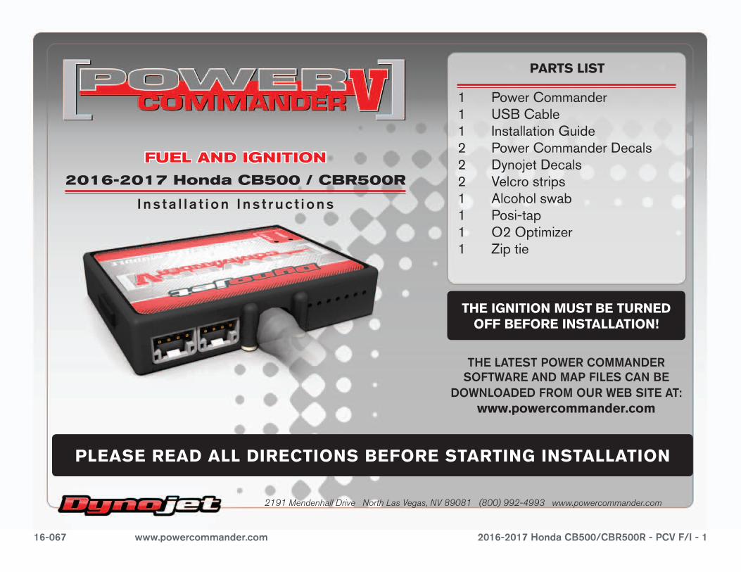
EXPANSION PORTS 1 & 2
Optional Accessories such as POD-300 unit or Auto-tune kit.
POWER COMMANDER V INPUT ACCESSORY GUIDE
Map - (Input 1 or 2) The PCV has the ability to hold 2 different base maps. You can switch on the fly between these two base maps when you hook up a switch to the MAP inputs. You can use any open/close type switch. The polarity of the wires is not important. When using the Autotune kit one position will hold a base map and the other position will let you activate the learning mode. When the switch is “CLOSED” Autotune will be activated. (Set to Switch Input #1 by default.)
Shifter- (Input 1 or 2) These inputs are for use with the Dynojet quickshifter. Insert the wires from the Dynojet quickshifter into the SHIFTER inputs. The polarity of the wires is not important. (Set to Switch Input #2 by default.)
Speed- If your application has a speed sensor then you can tap into the signal side of the sensor and run a wire into this input. This will allow you to calculate gear position in the Control Center Software. Once gear position is setup you can alter your map based on gear position and setup gear dependent kill times when using a quickshifter.
Analog- This input is for a 0-5v signal such as engine temp, boost, etc. Once this input is established you can alter your fuel curve based on this input in the control center software.
Crank- Do NOT connect anything to this port unless instructed to do so by Dynojet. It is used to transfer crank trigger data from one module to another.
ACCESSORY INPUTS
Wire connections:
To input wires into the PCV first remove the rubber plug on the backside of the unit and loosen the screw for the corresponding input. Using a 22-24 gauge wire strip about 10mm from its end. Push the wire into the hole of the PCV until is stops and then tighten the screw. Make sure to reinstall the rubber plug.
NOTE: If you tin the wires with solder it will make inserting them easier.
CRANK
ANALOG
SPEED
INPUT 1 (Grnd)
INPUT 1
INPUT 2 (Grnd)
INPUT 2
USB CONNECTION
2016-2017 Honda CB500/CBR500R - PCV F/I - 216-067 www.powercommander.com
16-067 www.powercommander.com 2016-2017 Honda CB500/CBR500R - PCV F/I - 3
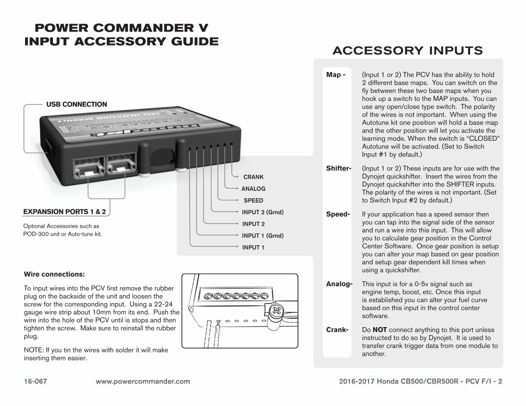
1 Removethemainseat,passengerseatandbothsidepanels.
2 Removetherighthandfairing.
3 Propthefueltankup.
4 LaythePCVinthetailsectiontemporarilyandroutetheharnessdowntheleftsideofthetailsection(Fig.A).
5 AttachthegroundwirefromthePCVtothenegativeterminalofthebike’sbattery(Fig.B).
6 RoutethePCVharnesstotheinsideofthefueltankbracket.
7 Unplugthestockwiringharnessfromeachfuelinjector(Fig.C).
8 Unplugthestockwiringharnessfromtheignitioncoils(Fig.C).
FIG.A
FIG.C
FIG.B
PCV
harn
ess
PCV
harn
ess
Grou
nd
16-067 www.powercommander.com 2016-2017 Honda CB500/CBR500R - PCV F/I - 4
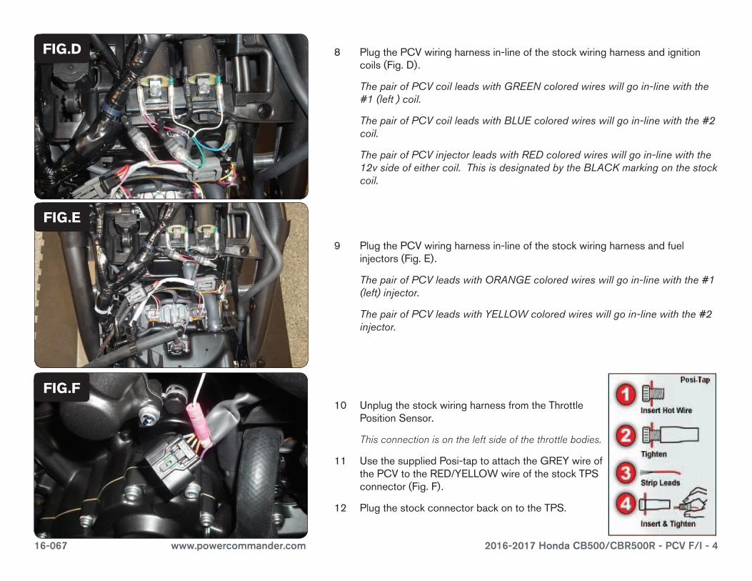
FIG.D 8 PlugthePCVwiringharnessin-lineofthestockwiringharnessandignitioncoils(Fig.D).
The pair of PCV coil leads with GREEN colored wires will go in-line with the #1 (left ) coil.
The pair of PCV coil leads with BLUE colored wires will go in-line with the #2 coil.
The pair of PCV injector leads with RED colored wires will go in-line with the 12v side of either coil. This is designated by the BLACK marking on the stock coil.
9 PlugthePCVwiringharnessin-lineofthestockwiringharnessandfuelinjectors(Fig.E).
The pair of PCV leads with ORANGE colored wires will go in-line with the #1 (left) injector.
The pair of PCV leads with YELLOW colored wires will go in-line with the #2 injector.
FIG.E
FIG.F10 UnplugthestockwiringharnessfromtheThrottle
PositionSensor.
This connection is on the left side of the throttle bodies.
11 UsethesuppliedPosi-taptoattachtheGREYwireofthePCVtotheRED/YELLOWwireofthestockTPSconnector(Fig.F).
12 PlugthestockconnectorbackontotheTPS.
16-067 www.powercommander.com 2016-2017 Honda CB500/CBR500R - PCV F/I - 5
FIG.G
FIG.H
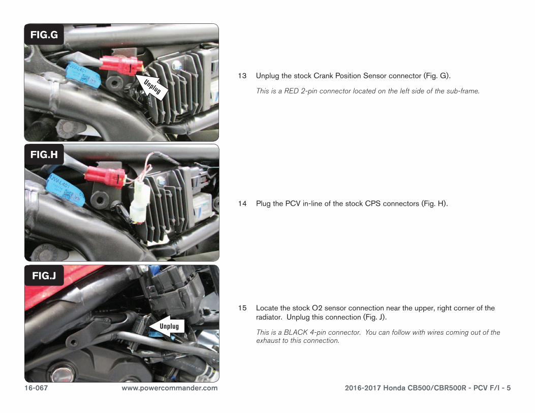
13 UnplugthestockCrankPositionSensorconnector(Fig.G).
This is a RED 2-pin connector located on the left side of the sub-frame.
14 PlugthePCVin-lineofthestockCPSconnectors(Fig.H).
FIG.J
15 LocatethestockO2sensorconnectionneartheupper,rightcorneroftheradiator.Unplugthisconnection(Fig.J).
This is a BLACK 4-pin connector. You can follow with wires coming out of the exhaust to this connection.
Unplug
Unplug
16-067 www.powercommander.com 2016-2017 Honda CB500/CBR500R - PCV F/I - 6
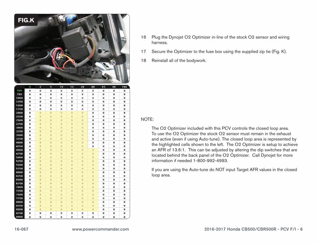
16 PlugtheDynojetO2Optimizerin-lineofthestockO2sensorandwiringharness.
17 SecuretheOptimizertothefuseboxusingthesuppliedziptie(Fig.K).
18 Reinstallallofthebodywork.
FIG.J
FIG.K
NOTE:
TheO2OptimizerincludedwiththisPCVcontrolstheclosedlooparea.TousetheO2OptimizerthestockO2sensormustremainintheexhaustandactive(evenifusingAuto-tune).Theclosedloopareaisrepresentedbythehighlightedcellsshowntotheleft.TheO2OptimizerissetuptoachieveanAFRof13.6:1.ThiscanbeadjustedbyalteringthedipswitchesthatarelocatedbehindthebackpaneloftheO2Optimizer.CallDynojetformoreinformationifneeded1-800-992-4993.
IfyouareusingtheAuto-tunedoNOTinputTargetAFRvaluesintheclosedlooparea.
![Digital Controller CB100/CB400 CB500/CB700 CB900400,500,700,900_modbu… · IMCB14-E1 CB100/CB400 CB500/CB700 CB900 [Z-1021] MODBUS Communication Instruction Manual ® RKC INSTRUMENT](https://img.pdfslide.us/doc/110x75/5b08e0457f8b9ac90f8d3596/digital-controller-cb100cb400-cb500cb700-400500700900modbuimcb14-e1-cb100cb400.jpg)